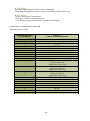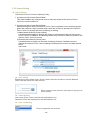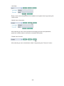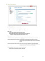
1
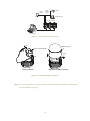
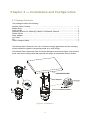
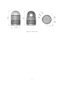
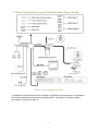
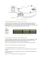
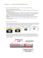
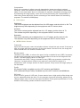
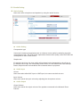
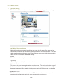
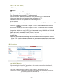
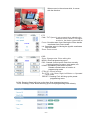
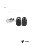
This unit complies with the requirements of the EC Directive 2004/108/EC, “EMC Directive”. The requirements for the susceptibility according to EN 55024 and the requirements for interference according to EN 55022 are observed for the operation on residential areas, business, light industrial premises and in small scale enterprises, inside as well as outside of the building. All places of operation are characterized by their connection to the public low voltage power supply system. Warning This is class A product. In a domestic environment this product may cause radio Interference in which case the user may be required to take adequate measures. i Note: This symbol mark is for EU countries only. This symbol mark is according to the directive 2002/96/EC Article 10 Information for users and Annex IV, and/or to the directive 2006/66/EC Article 20 Information for endusers and Annex II. Your MITSUBISHI ELECTRIC product is designed and manufactured with high quality materials and components which can be recycled and/or reused. This symbol means that electrical and electronic equipment, batteries and accumulators, at their end-of life, should be disposed of separately from your household waste. If a chemical symbol is printed beneath the symbol show above, this chemical symbol means that the battery or accumulator contains a heavy metal at a certain concentration. This will be indicated as follows: Hg: mercury (0.0005%), Cd: cadmium (0.002%), Pb: lead (0.004%) In the European Union there are separate collection systems for used electrical and electronic products, batteries and accumulators. Please, dispose of this equipment, batteries and accumulators correctly at your local community waste collection/recycling centre. Please, help us to conserve the environment we live in! ii IMPORTANT SAFEGUARDS /1. Read these instructions. 2. Keep these instructions. 3. Heed all warnings. 4. Follow all instructions. 5. Do not use this apparatus near water. 6. Clean only with dry cloth. 7. Do not block any ventilation openings. Install in accordance with the manufacturer's instructions. 8. Do not install near any heat sources such as radiators, heat registers, stoves, or other apparatus (including amplifiers) that product heat. 9. Do not defeat the safety purpose of the polarized or grounding-type plug. A polarized plug has two blades with one wider than the other. A grounding type plug has two blades and a third grounding prong. The wide blade or the third prongs are provided for your safety. If the provided plug does not fit into your outlet, consult an electrician for replacement of the obsolete outlet. 10. Protect the power cord from being walked on or pinched particularly at plugs, convenience receptacles, and the point where thy exit from the apparatus. 11. Only use attachments/accessories specified by the manufacturer. 12. Unplug this apparatus during lightning storms or when unused for long periods of time. 13. Refer all servicing to qualified service personnel. Servicing is required when the apparatus has been damaged in any way, such as power-supply cord or plug is damaged, liquid has been spilled or objects have fallen into the apparatus, the apparatus has been exposed to rain or moisture, does not operate normally, or has been dropped. 14. CAUTION - THESE SERVICING INSTRUCTIONS ARE FOR USE BY QUALIFIED SERVICE PERSONNEL ONLY. TO REDUCE THE RISK OF ELECTRIC SHOCK DO NOT PERFORM ANY SERVICING OTHER THAN THAT CONTAINED IN THE OPERATING INSTRUCTIONS UNLESS YOU ARE QUALIFIED TO DO SO. 15. Use Certified/Listed Class 2 power supply transformer only. 16. Don‟t remove the outer covering of this unit. iii TABLE OF CONTENTS Chapter 1 — Introduction ……………………………………………………………….. 1 1.1 Features ………………………………………………………………………………………... 1 Chapter 2 — Installation and Configuration ………………………………….………. 3 2.1 Package Contents ………………………………………………………………………..…… 3 2.2 Basic Configuration of Fastrax X18 Network Dome Camera System …………………… 5 2.3 Setting Network Dome Camera Termination ………………………………………………… 6 2.4 Setting Network Dome Camera Address (ID) ……………………………………………… 6 2.5 Setting Network Dome Camera Protocol …………………………………………………… 6 2.6 Connections ……………………………………………………………………………………. 6 Connecting to the RS-485 ……………………………………………………………………… 6 Connecting Video out connector ……………………………………………………………… 6 Connecting Alarms ……………………………………………………………………………… 6 Connecting the Network ………………………………………………………………………. 7 Connecting the Power ………………………………………………………………………… 7 2.7 Dome Network Camera IP Assignment ……………………………………………………… 7 2.8 Getting Started ………………………………………………………………………………… 8 Chapter 3 — Operation by Web Browser …………………………………..…………. 9 3.1 Accessing the Network Dome Camera by Web Browser …………………..……………… 9 3.2 Real-Time Monitoring …………………………….…….……………….………………………. 9 3.3 Network Dome Camera Setting ……………………………………………………………. 10 3.3.1 Video Setting …………………………………………….………………………………. 10 3.3.2 Audio Setting ……………………………………….…………………………………… 12 3.3.3 Alarm Setting ……………………………………..……………………………………… 13 3.3.4 PTZ Setting ……………………………………………………………………............. 16 3.3.5 System Setting ………………………………………..………………………………… 19 3.4 Help ……………………………………………………………………………………………… 27 Chapter 4 — Appendix …………………………………………………………………. 28 4.1 Product Specifications ………………………………..……………………………………..… 28 4.2 Troubleshooting ………………………………..……………………………………….……… 29 4.3 Glossary ………………………….………………….……………………………..…….…… 29 iv Chapter 1 — Introduction 1.1 FEATURES The Fastrax X18 Network Dome Camera, PC Software makes up the building blocks for any surveillance/security system. And Multiple Network Dome Cameras, no place is too large for monitoring. Extensible and flexible architecture facilitates remote control functions for a variety of external switching devices such as multiplexers and DVRs. Built-in 18x times optical power zoom camera with True Night Shot function. Full frame rate up to D1 (25fps@720x576) resolution compatible with MPEG4 standard. 80 Preset positions. 8 Tours consist of Preset, Auto-Scan and other Tours can be programmed with over 300 functions and Preset location. While moving, each Preset scan can be watched in smooth Vector Scan mode. 8 Auto Scans including vector scan and 1 Endless Auto-Scan. 8 Privacy zones. 2 Alarm inputs / 1 Aux outs (NC & NO). Variable speed from 0.1/sec to 90/sec. Turbo speed is Max 360/sec with Ctrl key pressed. Pan / Tilt speed is inversely proportional to the zoom ratio. Maximum speed is 380/sec when preset command. Programmable user preferences (alarm, preset, title, etc.). Up to 999 selectable camera addresses (Setting up by PC Software). Built-in RS-485 receiver driver. Built-in power-line surge protection and lightning protection. Built-in network interface (10Base-T/100Base-TX) for remote monitoring by PC. Interface protocol : TCP/IP, HTTP, UDP, DHCP, RTP, RTSP, SMTP, DDNS. Clear bubble with black liner (shelter) for concealing the camera. -1- Alarm Input 1 Alarm Output up to 2 <Sensor> <Siren> <Flashing Light> Up to 254 Camera PC Program [ Figure 1 – Typical System Configuration ] push bubble ring ass'y remove camera window screw push remove window assemble bubble ring ass'y [ Figure 2 – Assemble bubble ring ass’y ] Note: It is recommended to remove camera window for improving picture quality when you use bubble ring ass’y. -2- Chapter 2 — Installation and Configuration 2.1 Package Contents The package contains the following. Network Dome Camera ………………………….………………………………………………1 Bubble Ring ……………………………………………………………….………..………………1 Quick Guide ……………………………..…………………………………..……………………1 Assembly Screws for Attaching Fastrax X18 Network Camera ………….…………………3 Plastic Anchor …………………………………………………………………...…………………3 Plate Adaptor ………………………………………………………..……………………………1 I/O Cable …………………………………………………………..………………………………1 CD …………………………………………………………..………….…..………………………1 Cable Clamping Band .….…………….………………………………………………………....1 The Network Dome Camera is for use in surface mounting applications and the mounting surface should be capable of supporting loads up to 10lb (4.5kg). The Network Dome Camera‟s base should be attached to a structural object, such as hard wood, wall stud or ceiling rafter that supports the weight of the Network Dome Camera. Unlock SURFACE(CEILING) Plate Adaptor Lock Fastrax II Network Camera Lock [ Figure 3 – Installation ] -3- [Figure 4 – Dimension] -4- 2.2 Basic Configuration of Fastrax X18 Network Dome Camera System [Figure 5 – Basic installation diagram] The Network Dome Camera must be installed by qualified service personnel in accordance with all local and federal electrical and building codes. The system should be installed according to Figures 5 through 10. -5- [ Figure 6 – Layout of Switches ] 2.3 Setting Network Dome Camera Termination The device which is connected at end of line, whether it be a Network Dome Camera or keyboard controller, must have the cable for communication terminated by setting the appropriate DIP switch. Without proper termination, there is potential for control signal errors. Total length of the cable for communication should not exceed 1.2km. SW1 ON KSD02H 9A 1 SW1 1 2 Terminated ON ON Not terminated OFF OFF 2 [ Figure 7 – Setting Network Dome Camera Termination ] 2.4 Setting Network Dome Camera Address (ID) To prevent damage, each Network Dome Camera must have a unique address (ID). When installing multiple Network Dome Cameras using a multiplexer, it is suggested that the Network Dome Camera address match the multiplexer port number. If you want to set the address more than 999, you should contact the service provider. Refer to „3.3.4 PTZ Setting‟ section for detailed information. 2.5 Setting Network Dome Camera Protocol If a Network Dome Camera is to be installed with a Fastrax keyboard controller, select F2 protocol. Consult service personnel if a Network Dome Camera is installed with device other than a keyboard controller. Refer to „3.3.4 PTZ Setting‟ section for detailed information. -6- 2.6 Connections • Connecting to the RS485 The Network Dome Camera can be controlled remotely by an external device or control system, such as a control keyboard, using RS485 half-duplex serial communications signals. Connect Marked Rx+, Rx- to Tx+ and Tx- of the RS485 control system. • Connecting Video out connector Connect the video out(BNC) connector to the monitor or video input. • Connecting Alarms AL1 to 2 (Alarm In) You can use external devices to signal the Network Dome Camera to react on events. Mechanical or electrical switches can be wired to the AL (Alarm In) and GND (Ground) connectors. See “3.3.3 Alarm Setting – Alarm In” for configuring alarm input. GND (Ground) NOTE: All the connectors marked GND are common. Connect the ground side of the Alarm input and/or alarm output to the GND connector. NC(NO) (Normal Close or Normal Open : Alarm Out) The Network Dome Camera can activate external devices such as buzzers or lights. Connect the device to the NC(NO) (Alarm Out) and COM (Common) connectors. See “3.3.3 Alarm Setting – Alarm Out” for configuring alarm output. • Connecting the Network The Network Dome Camera supports the operation through the network. Therefore, it is necessary to connect a standard RJ-45 cable to it. Generally a cross cable is used for directly connection to PC, while a direct cable is used for connection to a hub. • Connecting the Power Connect the power of DC 12V to the Network Dome Camera. Use certified / Listed Class 2 power supply transformer only. 2.7 DOME NETWORK CAMERA IP ASSIGNMENT Dome Network Camera that is first connected to network basically has no IP address. So, it is necessary to allocate the IP address of Dome Network Camera with an IP allocation program. Open the program folder installed with the provided CD and execute “IP Setting Utility”. -7- 1. MAC Address Enter MAC address of the product for IP input. 2. IP Address Enter IP address to use. 3. Ethernet Adapter In case there are several network cards, select a card to use for the operation of Dome Network Camera. 4. Start Allocate input IP to the Dome Network Camera to use. When a completion message appears on “5” Status window in several seconds or minutes, input completes its process. You can add additional IPs to other devices continuously. [Figure 8 – IP Setting Utility] 2.8 Getting Started Once installed apply power to the Network Dome Camera. The Network Dome Camera will start a configuration sequence. FASTRAX II E Vx.xxx CAMERA TYPE xxxx WAIT DOME SETTING. INIT TILT ORGIN SET OK INIT PAN ORGIN SET OK INIT CAMERA SET OK [Figure 9 – Starting Camera OSD on CRT Monitor] PRESET No. 001 PRESET PRESET TITLE or AREA TITLE INFORMATION DISPLAY FUNCTION UNDER RUNNING EMPTY DATA ! CAMERA TITLE CAMERA ID T001 DOMEID:0001 W→360.0,090.0 PAN & TILT ANGLE VIEW DIRECTION [Figure 10 – OSD Position] -8- Chapter 3 — Operation by Web Browser 3.1 Connecting the Network Dome Camera by Web Browser ●Execute the Web Browser on the PC. ●Enter the Network Dome Camera address on the address window of the Web Brower and execute it. Ex) http://192.168.0.2/ (If the Network Dome Camera has no IP address or its IP address is wrong, users will fail to connect the Network Dome Camera. In this case, users will have to connect the Network Dome Camera the Web Browser after entering the IP address with the IP Utility.) ●Refer to „2.7 Network Camera IP Assignment‟ section for detailed information. ●If a security window for the ActiveX Controller installation appears, press the Confirm and install it. ●If it is not connected in the Internet, from the CD-ROM install the ActiveX Controller by manual operation. 3.2 Real-Time Monitoring The monitoring screen comes in four screen modes like D1, 640 X 480, 320 X 240, and 160 X 120. Users are allowed to select the most suitable one out of those modes. Please, adjust the mode in accordance with your PC specifications and monitoring purposes. In case of real-time monitoring with the Web Browser, one Network Dome Camera will be connected to just one Web Browser. However, this case is not suitable for monitoring various screens at the same time. If users are to monitor various images at the same time, please contact your dealer. -9- □HTTP tunnel mode When the screen is not indicated, check. (Notice: "unicast mode" only it is applied.) If users are to control the volume of a microphone and speaker connected to a user PC, they should adjust the user PC volume regardless of the microphone and speaker volume control set in Network cameras. 3.3 Network Dome Camera Setting Network Dome Camera setting is divided into video, audio, alarm, PTZ and system settings. And the detailed screen will be provided for each setting. 3.3.1 Video Setting The video setting is classified into Basic. The Basic menu includes a setting menu for real-time monitoring. Its setting only is enough to complete a setting for viewing the monitoring screen. The detailed setting menu is able to perform screen sizing, filtering, compressibility, and brightness control. Basic Setting Image Appearance Resolution It enables users to determine a basic screen size when having an access through the Web Browser or PC program. The screen size control comes in four modes like D1, 640 X 480, 320 X 240, and 160 X 128. Users can reset the selected screen size anytime while monitoring the screen on a real-time basis. Image filter The image filter control enables users to reinforce the image quality in a strong or weak way. The default is "disabled.” - 10 - Compression When it is necessary to adjust a smooth transmission status according to network situations, users can increase the compressibility to carry out the network transmission stably. On the other hand, when it is necessary to maintain a detailed monitoring screen by enhancing the image quality, users can do so by decreasing the compressibility. In ease case, please adjust this function according to the network status and monitoring purposes. The default is 2000(Kbps). BCS Adjust Brightness The screen brightness can be adjusted from 0 to 255 stages, and the default is 128. The brightness may differ depending on the equipment and PC monitor status. Contrast The screen contrast can be adjusted from 0 to 127 stages, and the default is 73. The contrast may differ depending on the equipment and PC monitor status. Saturation The screen saturation can be adjusted from 0 to 127 stages, and the default is 64. The saturation may differ depending on the equipment and PC monitor status. MPEG4 Video Stream Frame rate Upon the real-time play, users should select a frame refresh rate per second. If the rate is high, the image will become smooth. On the other hand, if the rate is low, the image will not be natural but it can reduce a network load. Bit-rate control Variable bit rate (VBR) : It refers to the type of using a variable bit rate (VBR). Increase a bit rate for the image with much motion, and decrease a bit rate for the image with little motion. The basic setting value is a VBR type. Constant bit rate (CBR) : Using a constant bit rate (CBR) may guarantee a stable play. However, if a large amount of data is not required, it may cause the waste of a transmission rate. If a large amount of data is required, it may cause the image quality to be decreased. Profile SP (Simple Profile) is available up to the CIF resolution and 384kbit/s. ASP (Advanced Simple Profile) is available up to the 4CIF resolution and 8000kbit/s. GOV size Enter the GOV (group of VOP) size. If users want to have a high quality of fast image one by one, please decrease the value. For the purpose of general monitoring, please do not change a basic value. Such act may cause a problem to the system performance. For the details of GOV setting, please contact the service center. - 11 - 3.3.2 Audio Setting Basic Setting Users can use a microphone and speaker by using the audio function. Audio Setting Compression type Users can increase a transmission rate or enhance a tone quality by selecting an audio compression mode. The PCM 16-bit implements the best tone quality, while the PCM 8-bit corresponds to that of radio sound. Sample rate If a sample rate is low, the tone quality will go down but the transmission rate will go up. If a sample rate is high, the tone quality will be better, but the transmission rate will drop. Please, adjust its rate in accordance with a network status or purposes. Audio Input Source Users can select either MIC input or LINE input, but cannot use both at once. Input Volume Users can control the input volume by adjusting the microphone volume. Audio Output Output Volume Users can control the output volume of the speaker connected to the Network Dome Camera. - 12 - 3.3.3 Alarm Setting Alarm In Setting This function enables users to conduct the alarm input/output setting and event setting. Motion Detection Setting Motion information is processed by splitting the screen into 64 areas. Each area can be selected by clicking with the mouse, and green point shown in the selected area. The area which uses the motion information as an event is shown green point, while the area which does not use the information is indicated empty. Enable Check this item when using the motion information. -Sensitivity This sets up the sensitivity for the motion detection. -Motion dwelling time This sets up the event dwelling time when a motion occurs. This can be set in the range of 0 ~ 6 seconds. When an event occurs, the motion icon at the upper right blinks in red for the preset time period. When another motion occurs during the motion event, the dwelling time is extended on the basis of the occurring time of the second event. -Enable down FPS This feature decreases frame rate to about 1 FPS when no motion event occurs, while operates with the frame rate set in this item when a motion event occurs. - 13 - Alarm IN Port 1 Setting Type Select the operation mode of the Alarm Input 1. Select either „N.O.(Normal Close)‟ or „N.C.(Normal Open)‟ Alarm dwelling time [0~180] Designate a running time for alarm occurrence. Select one out of 0 to 180 seconds. Alarm IN Port 2 Setting Type Select the operation mode of the Alarm Input 2. Select either „N.O.‟ or „N.C.‟ Alarm dwelling time [0~180] Designate a running time for alarm occurrence. Select one out of 0 to 180 seconds. Alarm Out Setting Upon the alarm occurrence, this function enables users to receive a mailing or ftp service to the mail address designated by users. SMPT(eMail) Setting Sender: Enter an eMail address to send a mail. Receiver list: Enter up to 10 eMail addresses to receive a mail. Email test: Enter an eMail address to test for sending a mail. Test button : Test for sending a mail with a value entered. - 14 - FTP & JPEG Setting -FTP Settings Enable Checks to activate the FTP function. Sender name or IP: Enters the FTP IP address or host name to be received. Port: Enters the port number of FTP to be received. Remote Directory: Enters the location for saving the file of FTP to be received. Username: Enters the user's account when connecting to FTP. Password: Enters the user password for connecting to FTP. -JPEG Settings Sets up the creation condition, screen size, color and name of JPEG file to be sent to FTP. Pre event: Creates the JPEG file of chapter 1~5 for 1~2 seconds before the event is generated. Post event: Creates the JPEG file of chapter 1~15 for 1~2 seconds after the event is generated. Image size: Selects the size of JPEG file to be created among 160X120 and 320X240. Color: Selects the color or B&W of JPEG file to be created. Base name: Write in the basic name of file to be created. Except for the basic name, It is possible to add supplementary names for discriminating multiple files. Additional suffix: Selects one among date, time and the number of sequence created. None: Do not add supplementary names. Date Time: Adds the date and time when the file was created behind the basic name. Sequence: Adds the number in sequence of file creation behind the basic name. Event Setup IN-OUT Mapping By connecting the Alarm OUT operations to the events occurred from the Alarm IN, users can send an eMail or FTP Server. Alarm IN - Alarm IN comes in Motion, Alarm in port 1 and Alarm in port 2. Alarm OUT - Alarm: Operate the equipment connected to the Alarm OUT port to the events occurred from the Alarm IN. email: Send an eMail to events occurred from the Alarm IN. - 15 - FTP: Sends the captured picture to FTP by the event which occurs from Alarm input. □Enable mandatory alarm out: Enable alarm control to open/close contact. 3.3.4 PTZ Setting Basic Control Left or Right button: Go into the sub-menu items. Execute the command (exit). Change value. Navigate through the menu items. Up or Down button: Navigate through the menu items. - 16 - When mouse in the red area click, It moves with the direction. -PTZ PAN / TILT Speed: It sets a speed when adjusting the Network Dome Camera. The higher a value is, the faster a speed will be. Focus: Overrides auto focus. Moving the Zoom handle reactivates Auto Focus mode. Iris: Overrides auto iris. Moving the joystick reactivates Auto Iris mode. Zoom: Zoom control. -OSD Zoom: Change value. Enter editing title. MENU: Enters programming menu. ESC: Cancels current inputs. Exits from currently running functions or menu, error status, etc HOME: Immediately calls Home function. Deletes selected value or function in programming mode CTRL On: Control function. Ex) CTRL + Up, Down, Right, Left Button >> Operated turbo mode. PRESET: Pressing „Prst‟ will bring up the preset programming menu. SCAN: Pressing „Scan‟ will bring up the Auto Scan programming menu. TOUR: Pressing „TOUR‟ button will bring up the tour programming menu directly. - 17 - PTZ Setting -Device ID: Setting Network Dome Camera Address(ID) -Baud Rate: Setting Network Dome Camera Baud Rate. (Default 9600 bps) ETC Setting -Preset: Save preset. Recall preset. -Auto Scan: Calls Auto panning function. -Tour: Recalls programmed presets or functions sequentially. It will be able to control with the keyboard. -Keyboard Short Cut Key Keyboard Key Label (PC Keyboard) Function (Fastrax Control Keyboard) ← → ↑ ↓ Shift + → Shift + ← Shift + ↑ Shift + ↓ Shift + „1‟ Shift + „2‟ Pan left Pan right Tilt up Tilt down Pan speed level up Pan speed level down Pan speed level up Pan speed level down PTZ mode OSD mode Focus mode - Page up (far focus) - Page down (near focus) Iris mode -Page up (open iris) -Page down (close iris) Zoom mode -Page up (zoon in) -Page down (zoom out) MENU ESC HOME CTRL PRST SCAN TOUR PTRN f i z m ESC h, HOME Ctrl r s t p - 18 - 3.3.5 System Setting Users Setting This Network Dome Camera's Authority Policy 1. Anonymous User Access Permit Mode This mode enables any anonymous users to have an access to the Network Dome Camera to monitor and set it. 2. Anonymous User Access Denial Mode Upon selecting this mode, the Network Dome Camera operates in two authority groups. And it also requires a log-in process when users are to have an access to the Network Dome Camera to change a screen monitoring or setting. 1) Administrator Authority Group (admin) It enables administrators to change the screen monitoring and setting of the Network Dome Camera. In addition, this authority allows only one user to have an access to the Network Dome Camera at once. 2) General User Authority Group (user) It enables users to simply use a screen monitoring function. It disables users to change the Network Dome Camera setting but allows them to have a multiple access at the same time. User setting Enable anonymous viewer login: Check it when users do not want to use the Network Dome Camera without the user account. When using the user account, users have to try log-in at every access. Admin Setting User name: Enter a user name for the administrator use. Password: Enter the password for the administrator use. User List Setting Show a registered user account. - 19 - - Add User Enter a user name and password to be added, and register them by pressing the “Add” button. - Modify User Information After selecting a user to be corrected and changing its name and password, press the „modify‟ button to reflect the corrected information. - Delete User Account After selecting a user to be deleted, delete it by pressing the “Remove” button. - 20 - Date & Time Setting Date & Time Current Time: Indicate a current time. Date: Indicate a current day, month, and year. Time: Indicate a current day, month, and year. New Time Time Zone: Select a time zone to be used. Automatically adjust for daylight saving time changes: Check it if users are to apply the Summer Time. Time zone Synchronize with computer time: Synchronize the time with that of a current user computer. Synchronize with NTP server: Synchronize the time with that of the NTP server. Receive the time information from the NTP (RFC2030) server. Synchronize with date server: Enter the Time Server address to be synchronized. Receive the time information from the Time Server that complies with the Time protocol (RFC868). Set manually: Users enter a current time directly. Date: Enter a current day, month, and year. Time: Enter a current day, month, and year. - 21 - Network Setting Setting in regard to network can be executed. Settings for IP, DNS, Host Name, Port, and Network traffic can be established, along with setting for DDNS and RTP. Basic Setting Basic settings for IP, DNS, Host Name, and Port are possible, and possibly works as a adjustment role in reducing the overload of network bandwidth in use, by applying Network traffic capability. IP address Configuration Obtain IP address via DHCP : Obtain an IP through the DHCP automatically. Use Following IP address : Users enter a Network Dome Camera IP directly. DNS Configuration Obtain DNS server address via DHCP: Obtain the DNS information through the DHCP. Use Following DNS server address: Users enter the DNS information directly. Domain name: Enter a domain name to be used. Primary DNS server: Enter the first domain name server. Secondary DNS server: Enter the second domain name server address. Host Name Configuration Obtain Host Name via DHCP: Obtain a Network Dome Camera name from the DHCP automatically. Use Following Host Name: Users enter a Network Dome Camera name directly. - 22 - Services HTTP port: Enter a port to receive a service through the HTTP. Default Port Number is „80‟. RTSP port: Enter a port to receive a service through the RTSP. Default Port Number is „7070‟. Network traffic - Maximum bandwidth Set a limitation on user network resources by designating the maximum bandwidth. Unlimited: Selected if not influenced by a network-related program or equipment Without a limitation on the network bandwidth. Limited to: In case of sharing other network programs or equipment, it is possible to set a limitation on the maximum bandwidth in the unit of Mbit/s or kbit/s. DDNS Setting Internet Dynamic DNS When using the high-speed Internet with the telephone or cable network, users can operate the Network Dome Camera even on the floating IP environment in which IPs are changed at every access. Users should receive an account and password by visiting a DDNS service like http://www.dyndns.com/. Enable Check to get DDNS service to be available. DDNS Server: Select the ddns server. Registered host: Enter a host address. Username: Enter an ID to access to the DDNS server. Password: Enter a password to be used for accessing the DDNS server. Confirm: Enter a password again to confirm it. Maximum time interval: Set a time interval to synchronize with the DDNS server. Register local network IP address: Register a Network Dome Camera IP address to the DDNS server. - 23 - RTP Setting Have a setting for sending and receiving an audio or video on a real-time basis. Stream RTP after Network Dome Camera start-up Enter a destination IP and Port to send movie data automatically through the RTP while the Network Dome Camera has booting. Send to DHCP server IP: Send movie data to the DHCP server. Send to (Client) IP: Send movie data to other certain destination addresses. Use RTP destination Port: Available from 1024 to 65532, and the default is 5000. Do not send: Do not send a stream to the FTP until it is requested from a client. Enable multi stream Check it to send data for the purpose of saving them into an external extension storage right after the Network Dome Camera operates. -Send to secondary client ip: Enter an IP address of the external extension storage. -Use RTP destination port: Enter a Port number of the external extension storage. The Port number to be used is [1024 ~ 65532]. -Frame rate: Indicate a frame rate that is sent to the external extension storage when the multi stream works. Once the multi stream function is checked, the MPEG profile setting will be changed to the Advanced Simple Profile. RTSP/RTP settings Perform a multicast setting to send a video and audio to multiple users. (Up to 10 users) RTP destination IP Disable Multicast: Do no use the multicast. Enable Multicast: Use the multicast. - 24 - Multicast destination IP: Enter an IP between 224.0.0.0 and 239.255.255.255. Although it is empty, an IP will be entered automatically. RTP port: Enter a value between 1024 and 65532. RTP TTL: Enter a value between 1 and 255. If a network status is smooth, enter a lower value. On the other hand, if a network status is poor, enter a higher value. When there are many Network Dome Camera or users, a higher value may cause a heavy load to the network. For a detailed setting, please consult with a network manager. Language ▪ Language It will be able to select a user language. The type of language it will be able to select is the English, the French, the German, the Spanish and the Italian. Maintenance - 25 - Maintain Server < Restart > Restart the Network Dome Camera. < Userset > Initialize a user setting value of audio/video, alarm, etc. < Restore > Restore all the values except a network-related setting to a basic value. < Default > Restore all the setting values to a basic value. Upgrade Server Carry out the upgrade by importing an upgrade file and pressing the „Upgrade‟ button. During the upgrade, do not turn off the power of the Network Dome Camera. And try an access again after waiting five minutes or longer. Backup Save a setting value that users enter to the Network Dome Camera, to a user PC. Restore Import and apply a setting value saved to a user PC. Program Support Information Troubleshooting When problems occur during operation, please consult with an installer. Server Report If its support is requested, please attach a server report. Log & Reporte Users can check the system log and server report. - 26 - Logs Users can check the log for Network Camera operation by clicking the < Logs >. ■ Reports Users can check a server report by clicking the < Server Report >. Users can check a parameter by clicking the < Parameter List >. Program Information The following website will provide the support information for the Network Dome Camera system information and operation. 3.4 Help The Help information window will be provided as a popup window so that users can open and read it without a need for log-in. It will offer a description on setting and Help page by which users can manipulate the Network Dome Camera without a reference to the manual. - 27 - Chapter 4 — Appendix 4.1 Product Specification - 28 - 4.2 Troubleshooting If problems occur, verify the installation of the camera with the instructions in this manual and with other operating equipment. Isolate the problem to the specific piece of equipment in the system and refer to the equipment manual for further information. PROBLEM AREA TO CHECK No video Verify that power is connected to all pieces of equipment in the system. Verify that the power switches are in the ON position. Check the video connections. (see page 4) Poor video quality. Check that the BNC connectors are inserted properly. Check the voltage level of the network dome camera. Cable for video is shielded. Network Dome Cameras lose their positions. Reset the cameras using the Dome configuration menus. Check that the network dome cameras are inserted properly in the base. Check the voltage level of the network dome camera. Camera number does not match the number on PC Program or Web browser. Check the camera ID of the Network Dome Camera. Check PTZ setting on the PC Program and Web browser. Frame rate decrease. A connection is cut-off at short intervals. Change current value more lower resolution, compression rate and frame rate. Check network traffic and contact with network administrator. 4.3 Glossary Alarm Actions The assigned responses for the network dome camera when inputs change from normal to abnormal states. The dome may run a Preset, Pattern, or have no assigned action for each of the four dome inputs. The dome may also send alarm states to the host controller for processing. See also Input and Normal Input State. Areas Programmed start and end points of the dome's field of view around its pan axis. Each area is a part of a circular viewing area that extends around the dome. The areas can be different sizes. Up to 16 areas can be programmed for the dome. Automatic Gain Control (AGC) Allows for the amplification of the video signal in scenes with minimal ambient light. Many low-light scenes result in picture noise. As gain is increased, the picture noise is also amplified. When AGC is enabled, the value of the gain setting is based on feedback from the camera. When AGC is disabled, the camera uses the value set for the manual gain setting. The trade-off between picture level and noise may be adjusted when AGC is disabled. - 29 - On-screen Menu The text overlay menu system used for setting dome features. The utility is accessed using a keystroke combination. The utility provides settings for camera functions, zoom, alarms, text display, and password protection. Flip Allows the dome to automatically turn 180 degrees when the camera tilts to its lower limit and stays in that position for a brief delay. When the dome flips (rotates), the camera starts moving upward as long as the tilt control is kept in the down position. Once the control is released, the tilt control returns to its normal operational mode. The flip feature is useful when you need to track someone who walks directly beneath the dome and continues on the other side. Home Position The default position to which the network dome camera returns after an assigned period of inactivity passes. The default position may be a Preset, Tour, Pattern, or No Action. Input Alarm A connection point on the network dome camera that enables the system to monitor Input Devices. There are four inputs available for the network dome camera. Input Devices External devices that provide information about the condition of system components that connect to the inputs on the network dome camera. Typical input devices include door contacts, motion detectors and smoke detectors. IR Mode A feature of the camera that permits manual or automatic switching between color and IR (black-and-white) operation. When IR mode is active, clearer images may be obtained under low-light conditions. Line Lock Allows you to phase lock the video with the AC power line. When line lock is enabled, it prevents vertical video rolling when switching multiple cameras to a single monitor. If text appears slightly tinted on color monitors, disabling the line lock may prevent this problem. Name Information Relates to the display the dome name, the area where the dome is pointing, the name of the preset or pattern that is running, and alarm names. The display of each type of name setting can be enabled or disabled. When the display of camera or area title(name) is enabled, the information appears on the screen continuously. Preset, tour and pattern titles(names) appear only while they are active. Normal Input State Describes the expected state of a device connected to one of eight network dome camera‟s inputs. The normal state may be open or closed. When a device is not in its normal input state, an alarm is issued. North Position User-definable setting that may correspond to magnetic north or some well-known landmark. Used to approximate the camera dome's pointing direction when Direction Indicators are enabled. - 30 - Low Shutter Setting used to improve the quality of video obtained in extreme low-light situations. When the Low Shutter setting is enabled, low-light information is collected over multiple fields based on the Shutter Limit setting. As a result, video may appear blurred or choppy in extreme low-light situations. This setting does not effect camera operation in normal lighting situations. See also Automatic Gain Control (AGC). Preset Programmed video scene, based on a specific pan, tilt, zoom, and focus settings. Up to 80 presets may be programmed for the network dome camera. Privacy Zones Masked areas of the network dome camera's viewing area. These masks prevent operators of the surveillance system from viewing these designated zones. The Privacy Zones move in relation to the network dome camera‟s pan/tilt position. In addition, the apparent size of the Privacy Zone adjusts automatically as the lens zooms in or out. Up to eight Privacy Zones may be established for a network dome camera. Shutter Limit Setting used to define the maximum exposure time for the Open Shutter setting. The values for the setting range from 1/2 to 1/60. The default setting is 1/4. Vector Scan Move from start point to end point including tilt and zoom simultaneously and linearly. WDR Wide Dynamic Range Technology uses two shutter speeds in alternative video fields-high and normal- every 60th (or 50th) of a second and combines two fields into one progressive scan frame. It allows every detail to be captured accurately even if one portion of an image is brilliantly. Whether at the high shutter speed or normal shutter speed, the progressive scan CCD provides a horizontal resolution of 470 lines. As a result, combined fields yield a frame of high-quality images. White balance Adjustments in the color hue(red and blue) gains for a camera so that true white appears white in the image. It is normally compensated for by the automatic gain control. In some lighting conditions, you may need to manually adjust the red and blue settings for optimal viewing. When Automatic White Balance is enabled, the camera measures the image and automatically adjusts the red and blue settings to balance white. When Automatic White Balance is disabled, the camera uses the values set for the red and blue settings to balance white. - 31 - UK Mitsubishi Electric Europe B.V. UK Branch Office Visual Information Systems Division Travellers Lane Hatfield Herts AL10 8XB Telephone: +44 (1707)-278 684 Fax: +44 (1707)-278 541 GERMANY Mitsubishi Electric Europe B.V. German Branch Office Electric Visual Systems Gothaer Str. 8 40880 Ratingen Germany Telephone: +49 (2102)-486 9250 Fax: +49 (2102)-486 7320 SPAIN Mitsubishi Electric Europe B.V. Spanish Branch Office Ctra. De Rubi, 76-80 Apdo.420 08190 Sant Cugat del Valles (Barcelona) SPAIN Telephone: +34 (93)-565 3154 Fax: +34 (93)-589 4388 ITALY Mitsubishi Electric Europe B.V. Italian Branch Office Centro Direzionale Colleoni Palazzo Perseo Ingresso 2, Via Paracelso 12, 20041 Agrate Brianza, Italy Telephone: +39 (039)-605 31 Fax: +39 (039)-605 3214 The Netherlands Mitsubishi Electric Benelux A Division of Mitsubishi Electric Europe B.V. Niiverheidsweg 23A, 3611 RP Mijdresht Netherlands Telephone: +31 (297)-282 461 Fax: +31 (297)-283 936 Sweden Mitsubishi Electric Scandinavia Hammarbacken 14 Box750 SE-191 27 SollentunaSweden Telephone: +46 (8)-625 1000 Fax: +46 (8)-35 1132 FRANCE Mitsubishi Electric Europe B.V. French Branch Office Boulevard des Bouvets 92741 Nanterre Cedex IreLand Mitsubishi Electric Ireland A Division of Mitsubishi Electric Europe B.V. Westgate Business Park, Ballymount, Dublin 24. Ireland Telephone: +33 (1)-5568 5500 Fax: +33 (1)-5568 5731 Telephone: +353 (1)-419 8800 Fax: +353 (1)-419 8895 A