1
Arri SR2 – MANUAL
provided by my16mm.com
Guide to the
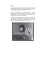
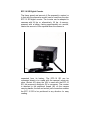
ARRIFLEX 16 SR II-E
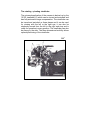
The 16 SA II-E is the basic model of the 16 SR II and
as such has the same basic filming functions.
The instruction manual can be used for both models; certain
sections must be included or excluded depending on the extent
to which the 16 SR II-E has been upgraded.
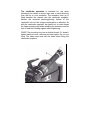
However, care must be taken that when the 16SR II-E has been
fully upgraded, only zoom lenses with diaphragm rods can fulfill
their function completely.
The electrical, optical and mechanical accessories can be used
unconditionally as well as the 120 m coaxial quick-change
magazine.
Contents
Mounting lenses
Working with the taking lens
Spring loaded diaphragm control
Automatic mirror shutter stop
Changing the 120 m /400 ft coaxial magazine
Loading the magazine
Film aperture cover
Magazine loop protector
Removing the exposed film from the magazine
Counter for exposed film
Film supply indicator for raw stock
The functions of the camera release on the housing
The drive motor and its electrical control system, pilot tone and start marking
The standard handgrip
The universal handgrip
The auxiliary handgrip
The rotating & pivoting viewfinder
The viewfinder extension
Operating the TTL -Si exposure meter
Fully automatic exposure control
Changing the fibre optic viewing screen
Light-weight support
The bridge and support plate
Matte boxes
The camera power supply
The 16SR time coding
Camera speed switch 24/25 fps or 50/60 Hz
Pilot tone output
Fuses
Full frame start marking lamp
Electrical accessories
The ARRIFLEX Image Stabilizer
Adaptation of a video system
EFC 16 SR digital counter
Film plane indicator
The asynchronous diode
The time counter
Service
Breakdown help when the automatic diaphragm
and shutter drive are defective
Technical Data
ARRIFLEX 16SR-HSII
5
7
7
7
8
10
16
16
17
19
20
21
23
24
25
26
27
29
30
31
33
34
35
36
39
41
43
43
44
45
46
48
49
52
53
53
53
54
55
56
58
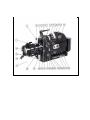
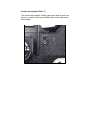
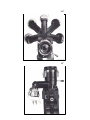
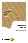
Illustration guide
1
Focusing grip
2
Zoom lever
3
Screw thread for zoom lever
4
Driver rings for diaphragm and focusing
5
Rotating and pivoting viewfinder
6
Collar nut for fitting the viewfinder to the camera, (this can only be carried out in
an authorized ARRI Service Center)
7
Collar nut for fitting-the eyepiece
8
Eyelet for carrying strap
9
Lock ring for diopter adjustment
10
Diopter adjustment
11
Eyecup
12
Film counter, exposed film
13
Wind-up magazine cover
14
Lens index mark, white (focal length! focus)
15
Retention pin for light-weight support
16
Protecting collar
17
Flexicable with spring-loaded holder for connector plate
18
Universal hand grip cable with 4 pole plug and safety stirrup '.
19
Camera shoe for light-weight support and flexicable connector plate
20
Lens index mark, white (diaphragm)
21
Lens release button (left)
22
Rosette for fastening an additional left side handgrip
23
Setting for DIN/ASA
24
Memory button (only cameras with built-in automatic exposure control)
25
Retaining lever
26
Camera release "start" position
27
Camera release "measuring” position
28
Camera release button
29
Camera release "0' , position
30
Camera release "test" position
31
Hinged knob for turning mirror shutter by hand
32
Hinged knob for locking magazine
33
Safety knob for magazine lock
34
35
36
37
38
39
40
41
42
43
44
45
46
47
48
49
50
51
52
53
54
55
56
57
58
59
60
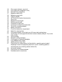
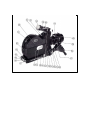
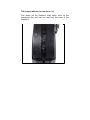
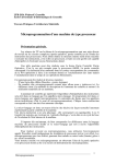
Film supply indicator, raw stock
Film supply side (magazine cover)
Release lever (magazine)
Magazine safety lock
Magazine snap catch
Carrying handle
3/8" thread for electrical accessories
Zoom ring
Magazine cover hinges
Running control light
Connector for pilot tone
Connector for electrical accessories
Thread for mounting adapter
Battery connection
Cover for electronics compartment
Eyelet for carrying strap
Film plane indicator cover plate over full frame start marking lamp
4-pole plugs for hand grip with electrical camera release (see pos. 18) or with
time counter
4-pole sockets
Rosette for fitting handgrip
Folding grip for fastening handgrip
Lens release button (right)
Additional lens index (red)
Press button for cable release (in flexicable for operating spring loaded
diaphragm control and preparing exposure control -measuring position simultaneously for unlocking release button 59)
Universal handgrip
Press button for camera release
Knurled screw for zoom lever
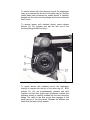
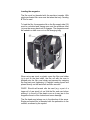
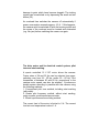
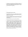
Mounting lenses
We supply zoom lenses with automatic diaphragm for use
with the ARRIFLEX 16 SR II; when the taking camera is
fitted with the automatic feature, these lenses can be used
without any restrictions for fully automatic exposure control.
Care must be taken that all lenses, with the white index
marking facing towards the exposure meter side, facing
towards the exposure meter side, are gently inserted to
prevent damage to the lens leader groove and the catch in
the mount, which fits into this groove.
All (unblimped) zoom and fixed focal length lenses with steel
bayonet or standard mount, suitable for use with the
ARRIFLEX 16 BL, can also be used with the ARRIFLEX 16
SR II without any restrictions whatsoever.
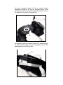
To remove lenses with steel bayonet mount: press release
button (55), turn the lens anti-clockwise and pullout of the
lens mounting flange.
To mount lenses with steel bayonet mount: the diaphragm
lever (a) is inserted into the slot of the catch ring (4), the lens
(white index mark positioned as stated above) is carefully
pushed into the lens mounting flange and turned clockwise
until it locks.
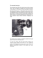
To remove lenses with standard mount: press release
buttons (21, 55) together and pull the lens out of the
mounting flange without turning it.
To mount lenses with standard mount: the diaphragm
lever(b) is inserted into the slot of the catch ring (4). Both
buttons (21, 55) are simultaneously pressed and held
together and the lens (index mark positioned towards the
exposure meter) is carefully pushed into the lens mounting
flange. The catch in the lens mount then engages in the
guide groove of the lens barrel. Release the buttons and
check that the lens is firmly seated. -
Working with the taking lens
Lenses with engraved index markings on both sides and with
double scales can be operated and read easily from the left
and the right hand side.
The zoom lever (2) is screwed into one of the sockets,
turned in the direction desired and fastened by tightening the
knurled screw (60).
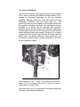
Spring loaded diaphragm control
The 16 SR spring loaded diaphragm mechanism works only
when used with 16 SR special zoom lenses with spring
diaphragm turned to "Zu/Off" position. The longer, rear rod
protruding from the lens (when in use, in the upper
position)~operates the iris diaphragm, the shorter rod is used
to select the fully automatic exposure control. Lenses with
axial or radial spring loaded diaphragm control can be used.
Automatic mirror shutter stop
Each time the camera is switched off the quartz controlled
motor stops the mirror shutter in such a position that the
finder is open for viewing. The opening of the shutter is 180°.
The mirror shutter can also be rotated by hand by turning the
hinged knob (31\).
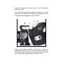
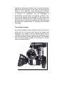
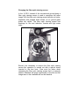
Changing the 120 m I 400 ft coaxial magazine
This process takes only seconds. Pull back the safety lever
(37) to the position "Offen/Open", depress the release catch
(36) at the same time
raising the magazine and removing it from the camera's
snap catch (38).
To replace the magazine, engage the hinge pin (a) in the
snap catch (38) and push the magazine downwards; a click
is heard when the magazine locks in position.
Finally, the magazine release catch (36) is locked by
pushing back the lever (37) to "Lock"; the camera is then run
a few turns slowly by pressing the test button (30) until the
film transport claw engages with a perforation hole.
Loading the magazine
The film must be threaded with the emulsion inwards. With
single perforated film care must be taken that only "winding
B" film is used.
To load the film, the magazine lid on the film supply side (35)
must be unlocked and swung open and the pressure roller
(a) must be swung back until it engages. The magazine must
be loaded in a dark room or in a film changing bag.
When using raw stock on plastic cores the film core holder
(g) is put on the feed shaft, the film roll with the core is
pushed onto the film core holder and secured by swinging
the flap back and tightening it. Daylight loading spools are
placed directly on the feed shaft and also secured.
CARE! Should self-wound rolls be used (e.g. a part of a
larger roll of raw stock) do not fold the film end over before
placing it in the slit of the plastic core as it may jam in the
magazine throat or film channel and cause damage.
The film head must always run in the direction of the arrow.
Single perforated film is threaded with the perforation to the
outside, as shown by the symbol
under the threading slot. .Film run in direction of the arrow
and the correct positioning of the perforations can only be
obtained when "B winding” film is used as previously
described.
The pressure roller (a) is then placed onto the film roll so that
the film roll is stabilized with the guiding edges; at the same
time It also operates the film supply indicator; Not for
daylight spools!
Slide the film head, which should be cut straight and through
the middle of a perforation hole, into the feed slot of the
magazine, turning the magazine gear slightly in the direction
of the arrow until a perforation hole is felt to be gripped; push
the film on until the film head reappears from the magazine
throat above the pressure plate. This operation can be made
lighter if the film head Is pushed into the feed slot before the
film roll or daylight loading spool is fixed to the feed shaft as
described above. The magazine lid is then shut and secured
by turning the hinged knob (32) to the right.
All further steps can be carried out in the light. The next step
is to pull the firm around the magazine until the loop length
marker is reached; the wind-up magazine cover (13) is
released and opened up and
the exact measured length of film is pushed, without
changing its length at all, into the magazine throat of the
take-up sprocket until the plastic magazine gear (b) moves in
the direction of the arrow. Only then can
the magazine gear be turned by hand in the same direction
{so that the film length remains unchanged) until the film
head appears in the take-up area.
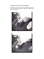
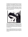
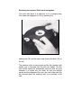
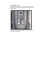
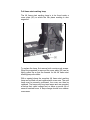
The pressure roller is then swung back and the film is
attached to the standard expansion film core (c) in the takeup compartment - (see illustration). Holding the magazine
gear stationary, the film core is turned in the direction of the
engraved arrow (i.e. clockwise) until the film is taut; the
magazine gear is then released and the film core is turned a
full turn to ensure that the film is tightly gripped. Finally the
pressure roller is swung back into its position so that the
edges are in alignment with the film; the magazine cover
then is replaced and secured.
When a plastic film core is used, the standard film holder is
pushed onto the wind-up pole until it engages and the plastic
film core is then pushed onto it. The slit for fastening the film
must point with its pointed corner in the run direction. The
film-head should only be folded once (NOT several times)
and inserted into the film core slit; the film is then made taut
as described above.
When using daylight loading spools the film core holder is
removed, the film is fixed in the spool column outside of the
magazine, a small amount of film is wound up, the spool is
set in the magazine and the film is made taut. Unlike in the
instructions
for using raw stock with plastic core, the pressure roller is
not swung onto the spool but remains latched away from the
spool. In this case the counter works only for the exposed
film (12). 1t must be reset to "0" every time the film is
changed.
It is important that the film which is slid under the hooks (d)
of the sprung pressure plate forms equal sized film loops
before and after the pressure plate. (When the magazine is
placed on the camera the hooks are no longer in contact
with the film).
The film aperture cover
When there is no magazine on the camera, the film aperture
cover should always be in place. It is easily fixed in position
with its snap closure and prevents the film aperture from
being damaged or becoming dirty.
The magazine loop protector
This protects the film loop, the magazine throat and the
guide rails from dirt and possible damage. With light
pressure it can be swung upwards to the magazine or pulled
down again. The loop protector should always be in place on
a loaded or empty magazine until it is fixed on the camera.
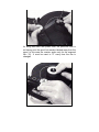
Removing the exposed film from the magazine
This must take place in a darkroom or in a changing bag.
First open the magazine lid (13) by pressing the
safety knob (33) and the same time turning the knob (32) to
the left.
The pressure roller is swung back and the film together with
plastic core is removed from the film core holder. The film
core holder cannot be accidentally removed with the core
because it is locked onto the shaft. As with the daylight
spools and the expansion film core, the core holder can only
be removed when the retaining latch (a) is pushed to the
side.
When expansion film cores are used the clamp lever is
pressed and the film end is released; at the same time the
diameter of the core is decreased so that the film roll can be
removed easily. The easiest way to remove the roll is to turn
the magazine over and let the film slip out onto the palm of
your hand. Place a plastic bobby in the film roll afterwards; it
is sufficient to keep the film stabilized even though it sits very
loosely. Under no circumstances whatsoever should the film
be pulled to make it sit tightly on the core as this only leads
to scratches on the exposed film.
Counter for exposed film (12)
This works with daylight loading spools as well as with raw
stock on a plastic core and must be reset to zero after every
film change.
Film supply indicator for raw stock (34)
This works via the pressure roller which rests on the
unexposed film and can be read from the back of the
magazine.
The functions of the camera release on the housing
The camera release button (28) is coupled with the mirror
reflex function so that the camera is quickly ready for
shooting.
In the "0" position the camera is switched off and the iris
diaphragm (when spring-Ioaded diaphragm control lenses
are used) is fully open. When the release is moved to the
measuring position (27), the iris diaphragm will close to the
value preselected on the diaphragm ring and the light
exposure meter switches on at the same time. The manual
adjustment of the iris diaphragm can be carried out now
according to the diaphragm aberration shown in the
viewfinder image.
When the release is then brought into the "start" position
(26), the camera run is switched on. When spring-Ioaded
diaphragm control lenses are used with cameras fitted with a
built-in automatic exposure meter, the necessary diaphragm
opening
is automatically set and can be controlled in the viewfinder.
When the camera is switched off ("0"position), the
diaphragm will return to the fully open position. If the camera
is again released, the diaphragm will close to the measuring
position of the last shot which is stored.
The "memory button"(24) enables the cameraman to retain a
momentary f-stop, This is of great value for selective
exposure measuring with zoom lenses and for panning,
when momentary fluctuations of the automatic exposure
control, occasioned by the subject, should be avoided.
When the release {28) is moved in the measuring position
(27) and the red knob (a) pressed, the memory button (24)
can be pulled downwards (switch on). When the release is
returned to the "0" position, the memory button is
simultaneously brought upwards and so switched off.
When the release (28) is in the measuring position, it is also
possible to swing the retaining lever (25) forwards to restrict
the release. The release can now only be moved between
"measuring" and "start" positions, for example, when
shooting over a long period of time with lenses without
spring loaded diaphragm. The iris diaphragm must be
manually opened for accurate focusing. The exposure meter
is in constant operation as long as it is connected to a
battery.
When the retaining lever in the release "0" position is swung
forwards, the release is blocked. The camera and the
exposure meter can no longer be switched on. This is .a
safety measure to prevent the camera being accidentally
switched on during transport and discharging the battery.
When the camera has been unused for a longer period of
time or when it is cold, the inching system should be
switched on for a short time to prevent
damage to parts which have become sluggish. The inching
system can be switched on by depressing the small red test
button (30).
An overload fuse switches the camera off automatically if
power consumption exceeds approx. 4.5 A. If this happens,
the camera must be switched off with the housing switch and
the cause of the overload must be located and eliminated
(e.g. film jam) before switching the camera on again.
The drive motor and its electrical control system, pilot
tone and start marking.
A quartz controlled 12 V DC motor drives the camera.
Frame rates of 24 and 25 fps can be selected (see para.:
switching over from 24 - 25 fps, and/or 50 - 60 Hz). Pilot
frequencies of between 50 and 60 Hz, proportional to the
camera motor speed, can also be selected. Synchronous
double system recording is possible with this camera using
the following methods:
1. Conventional pilot tone method; including start marking
(with cable).
2. Quartz pilot frequency method, without start marking,
using a quartz synchronous tape recorder.
3. Quartz synchronous time-coding method.
The current load of the motor is limited to 5 A. The current
load at room temperature is about 1 A.
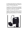
The standard hand grip
The standard hand grip with electrical press button release
(59) to start the camera is screwed onto the right hand side
of the camera to the rosette (53) and electrically connected
with the 4-pole plug (51 ). The special screw mount allows
the handgrip to be adjusted upwards and downwards and to
be displaced laterally. The standard hand grip is used mainly
when there is no special need in having the combined one
hand operation of automatic diaphragm and camera start, or
when standard lenses without automatic diaphragm are
used.
On request we can supply a left hand standard hand- grip
which is fixed to the left rosette (22).
To start the camera with the press button release, the
camera housing release (28) must be in the measuring
position {27) otherwise the camera will not start. This is to
prevent unintentional running of the camera with open
diaphragm.
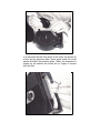
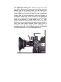
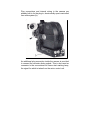
The universal handgrip
The universal handgrip with electrical press button release
(59) to start the camera and additional cable release (57) to
operate the automatic diaphragm, is, like the standard
handgrip, fastened to the right- hand side rosette (53) and
electrically connected with the 4-pole plug (51). The
protecting collar prevents damage to the flexible cable when
the camera is carelessly set down. The adjustable universal
handgrip is of special use for cameras with automatic
exposure control and with lenses with automatic diaphragm.
The handgrip rosette should first be positioned in the desired
setting and then fixed to the camera. The plug (51) is placed
in the socket (52) and then held securely in position with the
safety catch. The flexible cable (a) is then pulled back and
the square connector plate is pushed upwards into the shoe
for the lightweight support
until resistance is felt. Finally, the protecting collar (16) is
placed into the handgrip hole until it locks. To remove follow steps in reverse order.
The press button (57) for operating the automatic diaphragm
must be pressed before starting the
camera run as the press button is also a control mechanism
against accidental release. At the same time the exposure
meter is set in operation. With cameras with automatic
exposure meter control and with the lens diaphragm ring set
to position "A" (automatic), the iris diaphragm is
automatically set according to the lighting conditions. Only
then can the camera run be switched on. By pressing the
press button release (59) once again it springs back to its
previous position, switching the camera run off and releasing
the previously pressed button for operating the automatic
diaphragm.
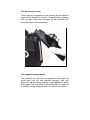
The auxiliary handgrip
An auxiliary handgrip is also available; it can be mounted on
either the left or the right hand side of the camera and
fastened to the rosette. It has no release function and is
intended for such situations as when the cameraman needs
to be able to hold the camera with both hands. The handgrip
can be moved vertically, parallel to the camera, to find the
most comfortable position.
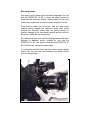
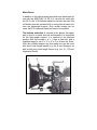
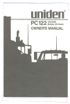
The rotating + pivoting viewfinder
The universal application of the camera is backed up by the
16 SR viewfinder (5) which can be turned and swiveled and
has fully automatic image compensation. The viewfinder can
be turned and swiveled on three planes and it can be used
for viewing with the left or the right eye; it can also be
steplessly moved from the left to the right end stop and is
ready for operation in every position. The viewfinder can also
be swung to the side. The three dimensional mobility allows
optimal positioning of the viewfinder.
360o
190o
25o
The viewfinder extension is intended for use when
shooting from a bird's or worm's eye view, or when shooting
from the hip or over obstacles. The extension tube (a) is
fitted between the camera and the viewfinder eyepiece.
Neither the universal panning/pivoting feature of the
viewfinder unit nor the image compensation is affected. As
with the viewfinder eyepiece, be careful not to cross-thread
the large mounting ring when installing the extension and be
sure to seat the locating nipples before tightening.
CARE! The mounting ring has a double thread. If it doesn't
tighten easily at once, unscrew and start again. Do not use
force. The same care must also be taken when fitting the
viewfinder eyepiece.
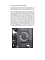
Operating the TTL-Si Exposure Meter
The exposure meter is powered by the camera battery. The
measuring range is 13 -31 DIN /16 - 1000 ASA at 5 -75 fps.
The film speed is selected by turning the knurled knob (23).
The reading field indicator needle is visible in the viewfinder,
to the left. When the film speed has been selected, the
indicator needle is brought into the center mark by adjusting
the iris diaphragm. The two outer Indicator marks, + and -,
indicate approximately 2 stops over or under exposure. The
indicator is compensated between when stationary and
when running, that is, a stop value which is selected before
the camera is running need only be changed when the
lighting conditions of the scene change. When the camera
starts running the indicator jerks slightly, but after one
second returns to its previous position. If filters are used
there is no need to take them into consideration, as, due to
their positioning, they are automatically taken into account.
Only when polaroid filters are used must the light be
measured beforehand and the filter factor then taken into
consideration during shooting as polaroid filters affect the
light measuring. Regardless of the focal length of the lens
used, in this exposure metering system about 25 % of the
central image area is measured.
Fully automatic exposure control
The ARRIFLEX 16 SR II is also available with fully automatic
exposure control; cameras without this feature can also be
fitted with it at a later date.
Automatic iris diaphragm control is only possible with 16 SR
spring-Ioad diaphragm lenses (which have a rod to adjust
the diaphragm).
The exposure meter is set as previously described.
The change-over to fully automatic exposure control is made
on the lens itself by turning the diaphragm ring to index
position A. When this is effected; the automatic control
circuit is activated when the camera switch is in the
measuring position together with the exposure meter. A
servo motor in the system moves the iris diaphragm until the
optimal setting, controlled through the viewfinder is obtained.
When filming with automatic exposure control, the
diaphragm ring must remain in position A. If the camera is
switched off, the diaphragm automatically opens fully again.
As with manual exposure control for speed, the setting is
held in a memory. This information is held in the memory
until new information is fed to the lens.
When filming with manual exposure control the lens is
"locked" to prevent accidental switch-over to position "A" for
fully automatic exposure control. Oh the other hand, the
change-over from fully automatic operation to manual
exposure measurement is simply achieved by turning the
diaphragm ring to 22 without "unlocking". In this way the
cameraman can react to special lighting conditions without
any delay.
Changing the fibre optic viewing screen
In the 16 SR II instead of the conventional ground glass a
fibre optic viewing screen is used to reproduce the reflex
image. With the fibre optic viewing screen definition is better,
especially with stopped down lenses, as no ground glass
grains are visible. The fibre optic viewing screen has
markings for film and television formats and light meter
scale.
Should it be necessary to remove the fibre optic viewing
screen this operation is carried out with a special clamp
inserted in the lens bore. Care must be taken when
reinserting the fibre optic viewing screen that it is securely
seated, otherwise the image reproduced on the film and the
image seen in the viewfinder will not be identical.
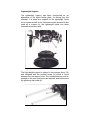
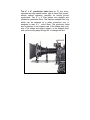
Lightweight Support
The lightweight support has been constructed as an
alternative to the tripod bridge plate, for filming from the
shoulder. It is used as a support for the lightweight follow
focus system as well as for the bellows matte box and is also
used as a support for the lightweight matte box when
standard lenses are used.
The light-weight support is placed in the camera shoe (19)
and fastened with the knurled screw (a) which is found
between the two support rods. The accessories can now be
pushed on the rods, positioned as required, and held secure
by tightening the screw (b).
The bridge and support plate
With the bridge plate the cameraman can evenly distribute
the weight of the camera when it is being used on a tripod. It
is mainly used with extremely long lenses or when several
accessories are used at the same time. The base plate (a) of
the bridge plate (b), is fastened with the tripod thread to the
tripod.
The upper part, to which the camera is secured, can be
moved forwards and backwards on the dove-tail guide until
the optimal centre of gravity is found, and then fastened.
When the clamping lever (c) is released the camera can be
removed in seconds from the tripod.
The bridge plate support rods (d) can be adjusted and are
used to support the following accessories: universal follow
focus system, servo zoom, lens supports and the production
matte box.
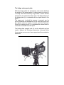
Matte Boxes
In addition to the bellows matte box which was developed for
use with the ARRIFLEX 16 SR II (it can also be used with
the 35 III), the 16 St bellows matte box can also be used; the
old holder must be replaced with a new guide rail which fits
onto the lightweight support. Only certain lenses can be
used; the16 St universal matte box cannot be modified.
The bellows matte box is secured in two places: the upper
part is fixed to a matte box rod and beneath it is supported
on the light-weight support; it is secured in the required
position with the screws a, b, c. It has a fixed slot and a
rotatable stage for two 3" x 3" or 4" x 4" or 94 mm dia. filters.
With the suitable adapter ring this matte box can be used
with short focal length lenses (e.g. the 8 mm Distagon) as
well as with long focal length lenses (e.g. the 10 - 150 mm
Angenieux-Zoom).
The lightweight matte box is fastened to the front of the
lens with a clamp ring. To ensure a close fit there are lens
adapter rings for the different lenses. For zoom lenses (with
the exception of the Zeiss-Vario-Sonnar f 1.8 / 10 -100) a
round rubber hood should be used; for fixed focal length
lenses (and the before-mentioned Zeiss-Vario-Sonnar) a
rectangular rubber tube should be used. As the lightweight
matte box is used mainly for news reporting, a rotatable filter
stage is unnecessary. A holder takes two 3" x 3" filter
frames. Should the Vario-Sonnar f 2.8/ 10 -100 mm be used,
the focus lever can be extended forwards with an extension.
With fixed focal length standard lenses which have a
rotatable front ring for setting the iris diaphragm, we
recommend the use of the additional support for attaching
the lightweight matte box to the lightweight support.
The 4" x 4" production matte box for 16 mm zoom,
standard and high speed lenses, with its three filter planes,
affords optimal operation versatility for motion picture
productions. Two 4" x 4" filter frames are rotatable and
slidable for graduated filters. The likewise rotatable filter ring
which can be replaced by a reflex prevention ring, is
designed to take 4 ½”, round filters. The production matte
box is fastened to the support rods of the bridge plate (see
also »The bridge and support plate«) or the support plate
and can be swung away through 90° to change the lens.
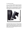
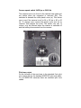
The camera power supply
A 12 V, 1.2 Ah battery is plugged into the back of the camera
and requires no cable. At 20°C its capacity is sufficient to
expose a maximum of 6 x 120 m of film. When using this
battery, a special battery adapter is plugged into the power
connection socket (47) and tightened with a screw; the
battery is pushed into the adapter and tilted onto the hinges
of the magazine. The camera is now ready for operation.
The camera can also be run from a 12 V battery connected
with a power cable (mode) KCU). The 4-pole battery
connecter and its cabling is identical to that used with the
ARRIFLEX 16 BLEQ and the ARRIFLEX 35 BL. The camera
battery is used to run the quartz controlled drive motor, the
exposure meter and automatic diaphragm control as well as
all the electrical accessories.
To recharge the plug-in battery there is available the NCL
SR II two-output battery charger which is designed for
normal and accelerated charging, automatic switch off and
automatic 110 / 220 V mains voltage selection.
Also available for the ARRIFLEX 16 SR II is the Energy Set
comprised of an NC 12 / 4 E camera battery with a capacity
of 4 Ah and a fully insulated NCL 12 / 4 E battery charger
with automatic 110 / 220 V mains voltage selection. The
charging unit can be switched over from 50 / 60 Hz.
The battery which has a carrying handle, can also be
attached to the cameraman's belt or shoulder strap. The
compact PPL 12 V high-capacity dry battery is used mainly
when battery charging is impossible. It is not rechargeable
but has a capacity to expose between 20 -30 120 m rolls of
film.
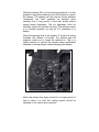
The 16 SR time coding
The ARRIFLEX 16 SR II is optically and mechanically
designed to accept the internationally planned (EBU) time
coding system.
The film is exposed on the opposite side of the claw, two
frames below the gate (a).
Plug connections and internal wiring in the camera are
already built in for the plug-in, electronically quartz controlled
time code system (b).
An additional plug connection inside the camera is provided
to connect the recorder diode module. This is also used as
connector to the conventional full frame start marking lamp,
the signal for which is taken from the motor control unit.
Camera speed switch 24/25 fps or 50/60 Hz
The switches are to be found in the camera base plate and
are visible when the magazine is removed (48). The
switches lie beneath the clear plastic cover (a). This allows
one to see if the camera is set for 24 or 25 fps or 50 or 60
Hz. To change over, remove the plastic cover and set as
required, then replace the cover. The switch over can, of
course, on)y be effected when the camera is switched off
and the battery disconnected from the camera.
Pilot tone output
On the left side of the rear base is the standard 5-pin pilot
tone output (44) for the standard ARRIFLEX pilot tone cable.
For all ARRIFLEX cameras there are standard pilot tone
cables.
Fuses
To prevent damage to the electronics and the internal
camera wiring from short circuiting inside the camera there is
an electronic plug-in fuse for the motor control unit.
When the magazine is removed and the battery
disconnected from the camera, the plastic cover (b) is
removed (with a coin) and the electronic plug-in fuse can
easily be removed with a special clamp.
2 reserve fuses are located in the plastic cover . When they
are removed from the plastic cover the ends of the fuses
must be bent at right angles so that they fit easily in place.
Replace the plastic cover and procure new fuses.
Full frame start marking lamp
The full frame start marking lamp is to be found under a
cover plate (50) on which the film plane marking is also
engraved.
To replace the lamp, first remove both counter sunk screws.
When the magazine is removed the cover plate (50) can be
lightly pulled up so that the threads for the full frame start
marking lamp are visible.
With a special clamp the complete full frame start marking
lamp can be lifted out and replaced with a new one. The new
lamp must be securely positioned, the cover can then be
replaced. The lamps are long-term lamps and are operated
at below their rated voltage and so have a service life of
several hundred hours. A lamp change should be a seldom
occurrence.
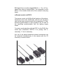
Electrical accessories
a) Panhandle switch model RCSR
The panhandle switch can also be used with the ARRI FLEX
35 BL, the 16 BLEQ and the 16 St with universal motor; its
cable plug is inserted into the middle socket (45) of the
camera's rear plug board and enables the camera to be
switched on and off at
the panhandle.
The camera can only be started from the panhandle when
the camera release (28) is placed in the "measuring position"
or the push button (57) on the universal hand grip is
operated. This electrical locking function prevents the
camera being switched on in error as well as filming with
open diaphragm.
b) Variable speed unit (VSU)
The VSU unit, which is attached to the panhandle, is also
plugged into the middle socket (45) of the camera's rear plug
board. As with the panhandle switch RCSR the camera is
also switched on and off by pressing the round button. Close
to it is to be found a toggle switch; when in position "cam.
ref". (camera reference), the camera operates at a constant
quartz controlled speed; when in position "var". (variable) the
camera can be operated between 5-75 fps (with the
ARRIFLEX 16 SR-HS II, 10 -150 fps).
c) Phase shifter unit PHU
The phase shifter unit is used for correcting the phase
relationship of the quartz-controlled camera when filming
from television monitors. The connection for the PHU is the
middle socket (45) of the camera's rear plug board.
d) The EXS II external synchronizer , The EXS II external
synchronizer with BAS signal, built-in remote ON/OFF
switch, out-of-synch indicator, camera type selection switch
and built-in phase-shifter is used for synchronizing the
camera with another camera, with the mains, or with the
BAS signal from a monitor (signal 50/60 Hz, > 1 Vpp, <10 Vpp,
signal form sinus or impulse, BAS). The connection for the
EXS II is the middle socket (45) of the camera's rear plug
board.
e) Remote control unit FSZ II
The remote control unit fulfills all the functions of the abovedescribed control units. Additionally, with this unit, the frame
rate can be quartz synchronously set in steps from 6 -75 fps.
External synchronization is also possible at 25, 50 and 75
fps, permitting synchronization with the lighting supply
mains.
For mains synchronization with the FSZ If or the EXS II the
mains sync transformer NSYTR 2 for primary 220 V,
secondary 1 V sec is necessary.
Any two of the above-mentioned external accessories can
be connected simultaneously to the camera with the ZV
accessory connector board.
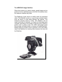
The ARRIFLEX Image Stabilizer
When this accessory is used a steady, upright image can be
produced in the viewfinder and on the film in situations when
the camera is shaken and jolted.
The Stabilizer is light and so is ideally suited for hand-held
shots. The Stabilizer works on a gyro-scope principle which
must be borne in mind when panning the camera. The
maximum panning speed is 4o/sec. The Stabilizer can be
used horizontally or vertically; it is fixed onto the bridge plate
rods and, according to the length of the lens used, is held in
position with a clamp screw. The ARRI light-weight matte
box provides sufficient shade; if required, an additional lightweight matte box holder can be mounted on the rear clamp
ring of the Stabilizer for inserting filters between the lens and
the Stabilizer.
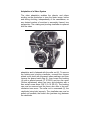
Adaptation of a Video System
The video adaptation enables the director and others
working on the production to view the finder image, before
and during shooting, independently of the cameraman, on
any desired number of monitors in accurately framed, true
perspective. The rotating and pivoting viewfinder is replaced
with the video
adaptation and is fastened with the collar nut (6). To remove
the rotating and pivoting viewfinder, unscrew the chrome
plated cover plate with engraved index markings and then
remove the geared catch ring (4); then loosen the bushing
(A) with a special wrench (S 16 SR-3) and turn the worm
(friction adjustment) about ten turns anti-clockwise with a
hex socket screw driver SW 2 (A 16 SR-16). The bushing
can now be removed and the worm also after a few anticlockwise turns more. The collar nut is unscrewed (6), the
viewfinder being held securely. The viewfinder can now be
pulled out forwards; the friction disc (pertinax ring) between
the viewfinder
and the primary optics must also be removed. The video
adaptation is mounted reversing the above-described steps.
The friction disc is not used. Care must be taken that the
adapter arm for securing the viewfinder (seen in taking
direction) is on the left side of the camera housing. It is not
possible to turn the video adapt ion through 180° for left eye
viewing.
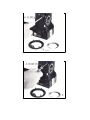
EFC 16 SR Digital Counter
The frame speed and amount of film exposed in meters (or
in feet with the alternative model) can be read from the new
EFC 16 SR digital counter. The counter can be adapted to
cameras with 24 fps or, alternatively, 25 fps. A memory,
powered with a battery lasting approximately six months,
retains the amount of film exposed when the camera is
separated from its battery. The EFC-16 SR can be
connected directly via a cable with the camera's electronic
shoe. (Socket 45); when the VSU is used with the EFC-16
SR, the accessory distributor ZV is necessary. The counter
is attached to the additional thread (40) on the camera
carrying handle; the ball and socket joint connection enables
the EFC-16 SR to be positioned in any direction !or easy
reading.
Film plane indicator
The film plane indicator (50) is used for precise evaluation of
the taking distance, with close shots, between the camera
and the subject or for deciding the distance for the
microphone. The indicator is engraved in the cover of the full
frame start marking lamp which is found on the right hand
side of the camera (seen in taking direction).
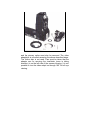
The asynchronous diode
When the camera is started at the right of the view- finder
image a red dot is visible which disappears after a short
time. This is a signal sent by the asynchronous diode, and
the signal remains until the selected frame speed is reached.
Should the voltage drop the dot also appears and is so an
indication that the battery must be exchanged. In this case
the rear red control lamp no longer blinks but emits a steady,
weak light.
The time counter
The time counter, when the camera is fitted with this
function, is to be found above the 4-pole plug (51). It is a
graded rod in which there is a mercury column with marker.
When the camera is operated for 100 hours the marker
travels from left to right, and then travels in. the opposite
direction in the next 100 hours of operation. The exact
operating time of the camera can be determined and
controlled.
Service
For a trouble-free film run, especially with regards to
steadiness of image, the camera side film channel must be
kept absolutely clean. Always check that no emulsion
deposit has built up. Emulsion deposits on the film gate can
alter film focal distance which, when lenses with a very short
focal length are used, can lead to unsharpness.
The film channel is easily accessible and can be cleaned
with a PVC rod. We recommend the use of the ARRI plastic
film track cleaning rod. Under no circumstances attempt to
use metal or other hard tools.
The function of the magazine film guide is also of great
importance. Special care must be taken of the film pressure
block. When the magazine is placed on the camera this
automatically forms a protective film guide. The film is
pressed against the pressure gate with a carefully measured
force. To adjust this force, a special unit is necessary which
also can be used to control the movement of the pressure
block.
Apart from, these steps, the ARRIFLEX 16 SR II is basically
maintenance free. Neither oil nor grease is necessary;
Authorized ARRI repair shops are available for Servicing.
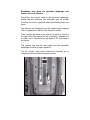
Breakdown help when the automatic diaphragm and
shutter drive are defective
Should the servo motor used for the automatic diaphragm
setting become defective, the automatic and iris shutter
functions can still be operated when the following steps are
taken:
First remove the magazine from the camera (see changing
120 m magazine) so that the film channel is visible.
Then remove the black round sticker (a) which is found to
the right of the film channel on the cover plate. Beneath it is
a screw; turn it clockwise through approx. 90° and replace
the sticker.
The camera can now be used again and the automatic
diaphragm function is again operative.
The iris shutter f-stop must however-be manually set in
conjunction with the manual exposure meter.
Technical data
ARRIFLEX 16 SR II/16 SR-HS II
Measurement
Length: measured from lens flange
Viewfinder horizontal
LxHxW
Viewfinder vertical
LxHxW
mm
264 x 195 x 160mm
264 x 287 x 100
Weight
Camera body, 3,2 kg (7.05 Ibs)
120 m magazine 2,2 kg (4.85 Ibs)
Magazine
120 m coaxial quick-change magazine for use with film on
plastic bobby, "Winding B" or (with increased noise level) 60
m daylight loading spools; hinged lid
Film movement ,
Kinematic, jointed pulldown; registration pin; image
steadiness is 1o/oo of frame height. Registration pin position
+3
Shutter
180° one-piece, mirror shutter intersects optical axis 9 mm
before the focal plane at 45°, reflection upwards
Noise level
16 SR II
25 + 1 dB (A)
16 SA-HS II 32 dB (A) at 24 fps, 56 dB (A) at 150 fps
Lens mounting flange
Steel bayonet, flange focal distance 52 mm, opening 41 mm
Lenses
All standard unblimped ARRIFLEX 16 BL lenses can be
used
Viewfinder
Universally adjustable with automatic image compensation,
removable eyepiece, 10 fold magnification
Focussing screen
Interchangeable fibre optic screen for TV or cinema format .
Exposure control
Electronically governed. Data input only for film speeds 1331 DIN /1000 ASA. Indication range ± 2 stops
Fully automatic exposure control
Available with or without automatic exposure control,
suitable for later fitting for fully automatic exposure control
Power
12 Volt, Connector: 4-pin DIN 15931
Plug.in battery
12 Volt,-1,2 Ah
Camera motor
DC quartz precision motor, 1500 rpm at 25 fps, 1440 rpm at
24 fps, quartz accuracy 5x10⁻⁶
Frame speeds
Quartz 24/25 fps
Manual speed control
With variable speed unit (VSU) Variable 5 -75 fps (16 SR-HS
II 10- 150 fps)
Power consumption
Approx. 1 Amp at room temperature
Safety
Overload switch cuts off power when load exceeds approx.
4.5 Amps.
Release
2 step release for diaphragm operation
Temp. range
-20°C to + 50°C (-4°C to + 122°F)
Pilot tone
Pilot tone supply DIN 15575, pilot frequency 50 or 60 Hz
Start marking
Automatic full frame start marking
Time Code
Prepared to accept a time code generator
The ARRIFLEX 16 SR-HS II
The ARRIFLEX 16 SR-HS II is a development of the 16SRHS. The exposure control system is the same as in the 16
SR II, the automatic exposure control is, however, a
standard fixture.
Both manual exposure control and automatic exposure
control (when using lenses with spring loaded diaphragm)
can thus be used, The frame speed of the 16 SR-HS II can
be adjusted steplessly from 10 -150 fps with the Variable
Speed Unit (VSU). There is a special scale graded from 10 150 fps available for use with the VSU, but the standard 16
SR II scale graded from 5 -75 fps can also be used; the set
reading need only be doubled to obtain the actual frame
speed. With the exposure meter, the frame speed is
automatically taken into account.
The noise level, at 25 fps 32 dB (A) and at150 fps 56 dB (A),
is relatively low.
A trouble-free run for the complete frame speed range can
only be guaranteed when the threaded film is not colder than
-5°C (23°F). The camera is also fitted with a rev Iimiter which
automatically switches the camera off when a speed of 165
fps is reached. With the exception of the magazines, the
complete range of the 16 SR mechanical, optical, electronic
and electrical accessories can be used with the 16 SR-HS II.
The standard magazines for the 16 SR II are built with a
spring-Ioaded pressure plate and for a focal plane
measurement of 52 mm. The 16 SR-HS II needs a special
magazine with a rigid pressure gate and the high speed film
run makes a film channel with a focal plane measurement of
51,970 mm necessary. To avoid confusion with the
magazines, the 16SR-HS II magazines are finished in an
attractive grey.
Arri SR2 – MANUAL
provided by my16mm.com