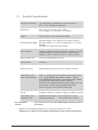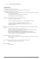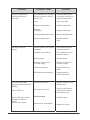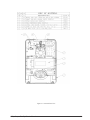
1
FreeStyle™ Portable Oxygen Concentrator Service Manual AirSep Corporation • 401 Creekside Drive • Buffalo, NY 14228-2085 USA Telephone: 716.691.0202 • 24-Hour Fax: 716.691.4141 • www.airsep.com Expedited Product Warranty Check service is always at your fingertips with AirSep: Type www.airsep.info/warranty_check/main.asp OR In the US or Canada, dial 866-873-9277 Air Travel with FreeStyle FreeStyle is approved for use on-board commercial aircraft per an addendum to FAA SFAR 106. For a current list of airlines that allow the FreeStyle POC for in-flight use by patient/ passengers with a valid medical prescription upon notifying the airline’s oxygen desk, visit the following on AirSep web site at the link below: http://www.airsep.com/medical/AirLinePOCs.html AirSep® is a registered trademark of AirSep Corporation. FreeStyle™ is a trademark of AirSep Corporation. MN126-1 Rev. B 07/12 Table of Contents Section 1.0 Introduction 1.1 Equipment Provider Responsibility 1-1 1.2 Important Notice and Symbol Explanations 1-2 1.3 Definitions of Symbols 1-3 1.4 FreeStyle Product Limited Warranty 1-4 1.5 FreeStyle Specifications 1-5 1.6 FreeStyle Classifications 1-6 2.1 Description of Operation 2-1 2.2 Operation Check 2-1 2.3 Alarm System 2-2 2.3.1 Start-up 2-2 2.3.2 Battery Status 2-2 2.3.3 Low Battery 2-2 2.3.4 Discharged Battery 2-2 2.3.5 Battery Charging 2-3 2.3.6 Battery Fully Charged 2-4 2.3.7 Cannula Disconnect 2-4 2.3.8 Performance Warning 2-4 2.3.9 FreeStyle Capacity Exceeded 2-4 2.3.10 General Malfunction 2-4 Section 2.0 Operation Check and Test of Oxygen Concentration 2.4 Oxygen Concentration Test and Specification 2-5 3.1 General Instructions 3-1 3.1.1 Connecting t o E x t e r n a l Power 3-1 3.1.2 Optional AirBelt Battery 3-1 Routine Maintenance by the Patient 3-4 Section 3.0 Patient Instructions 3.2 AirSep Corporation i – table of contents 3.2.1 Cleaning the Air Intake Gross Particle Filter 3-4 3.2.2 Alarm/Service Indicator 3-5 3.2.3 Nasal Cannula 3-5 3.2.4 Usage During Sleep 3-5 Section 4.0 Equipment Provider Maintenance 4.1 No Scheduled Maintenance 4-1 4.1.1 Air Intake / Gross Particle Filter 4-1 4.1.2 Product Filter Replacement 4-1 4.1.3 Compressor Servicing 4-2 4.1.4 Recording Maintenance 4-2 4.2 Infection Control 4-2 4.3 Cleaning and Preparing for New Patient Use 4-2 5.1 Components 5-1 5.2 Housing Removal 5-2 5.2.1 Removing Front Cover 5-2 5.2.2 Removing Back Cover 5-2 Section 5.0 Service 5.3 Internal Battery Replacement 5-3 5.4 PSA Removal 5-4 5.5 Compressor Replacement 5-10 5.5.1 Compressor Assembly Removal 5-10 5.5.2 Compressor Assembly Installation 5-12 5.6 Product Manifold Replacement 5-13 5.7 Solenoid Valve Replacement 5-14 5.8 Adsorbent Bed Replacement 5-15 5.9 Feed/Waste Manifold Replacement 5-17 5.10 Measuring System Pressure 5-18 5.11 Hour Meter Functionality 5-19 5.11.1 Icons 5-19 5.11.2 Power 5-19 5.11.3 Service LED 5-19 5.11.4 Toggle/Reset Switch 5-20 5.12 ii – table of contents Hour Meter Replacement 5-20 AirSep Corporation 5.13 Circuit Board Replacement 5-21 5.14 Motor Controller Board Replacement 5-25 5.15 Control/Key Panel Replacement 5-27 5.16 Fan Replacement 5-31 6.1 Pressure Profile Quadrant 6-1 7.1 General Troubleshooting 7-1 7.2 Troubleshooting Chart 7-2 8.1 Tools for FreeStyle Service and Maintenance 8-1 Section 6.0 Typical Pressure Profiles Section 7.0 Troubleshooting Section 8.0 Recommended Tools Appendix Exploded Drawings iii – table of contents Figure 1: FreeStyle — Internal Front View A-1 Figure 2: FreeStyle — Internal Rear View A-2 Figure 3: FreeStyle — PSA Assembly - Product Manifold A-3 Figure 4: FreeStyle — PSA Assembly - Feed/Waste Manifold A-4 AirSep Corporation 1.0 Introduction 1.1 Equipment Provider Responsibility All Equipment Providers of the FreeStyle™ Portable Oxygen Concentrator must assume responsibilities for handling, operational check-out, patient instruction, and maintenance. These responsibilities are outlined below and throughout this manual. This unit is not to be used for life support. Geriatric, pediatric, or any other patients unable to communicate discomfort while using this unit may require additional monitoring. Patients with hearing and/or sight impairment(s) may need assistance with monitoring alarms. As an Equipment Provider, you must do all of the following: ■ Inspect the condition of each FreeStyle unit immediately upon delivery to your business location. Note any sign of damage, external or internal, on the delivery receipt, and report it directly to both the freight company and AirSep Corporation immediately. ■ Check the operation of each FreeStyle unit before delivery to a patient. Always operate the unit for a minimum of 10 minutes, and check that the oxygen concentration level is within specifications, as described in Section 5 of this manual. ■ Deliver FreeStyle units only to patients authorized by a physician’s prescription. FreeStyle must not be used as a life-supporting device. ■ Instruct patients how to use FreeStyle in conjunction with the Patient Manual. ■ Instruct patients to notify their physicians and/or Equipment Providers if they experience any signs of discomfort. Instruct each patient to perform routine maintenance of the air intake gross Filter. (Refer to Section 3.2.) ■ ■ Be available to service each patient at any time. ■ Maintain FreeStyle in accordance with Section 4.0. ■ Repair components and replace parts only as outlined in this manual. Use only AirSep parts for replacement in FreeStyle Oxygen Concentrators. ■ Refer to the “FreeStyle Product Limited Warranty”, Section 1.4 of this manual, if replacement of parts is required within the warranty period. AirSep Corp. — FreeStyle Service Manual 1-1 1.2 Important Notice and Symbol Explanations As you review both the FreeStyle Patient Manual and this FreeStyle Service Manual, pay special attention to the WARNING, CAUTION, and NOTE messages. They identify safety guidelines or other important information as follows: Warning – Describes a hazard or unsafe practice that if not avoided can result in severe bodily injury, death or property damage Caution – Describes a hazard or unsafe practice that if not avoided can result in minor bodily injury or property damage Note – Provides information important enough to emphasize or repeat DO NOT OPERATE THIS EQUIPMENT WITHOUT FIRST READING AND UNDERSTANDING THIS MANUAL. IF YOU ARE UNABLE TO UNDERSTAND THE WARNINGS AND INSTRUCTIONS, CONTACT YOUR EQUIPMENT PROVIDER BEFORE ATTEMPTING TO USE THIS EQUIPMENT; OTHERWISE, INJURY OR DAMAGE MAY RESULT. Smoking while using oxygen is the number one cause of fire injuries and related deaths. You must follow these safety warnings: Do not allow smoking, candles, or open flames in the same room with the device or within 5 feet (1.52 meters) of the oxygen-carrying accessories. Smoking while wearing an oxygen cannula may cause facial burns and possibly death. Removing the cannula and putting it on bedding, sofas, or other cushion material will cause a flash fire when exposed to a cigarette, heat source, or flame. If you smoke, these 3 steps may save your life: turn off the oxygen concentrator, take off the cannula, and leave the room where this device is located. “No Smoking – Oxygen in Use” signs must be prominently displayed in the home, or where the oxygen concentrator is in use. Patients and their caregivers must be informed about the dangers of smoking in the presence of, or while using, medical oxygen. 1-2 AirSep Corp. — FreeStyle Service Manual 1.3 Definitions of Symbols Symbols are frequently used on equipment and/or the manual in preference to words with the intention of decreasing the possibility of misunderstanding caused by language differences. Symbols can also permit easier comprehension of a concept within a restricted space. The following table is a list of symbols and definitions used with the FreeStyle Portable Oxygen Concentrator. Symbol Description ON (power switch on) Warning – Describes a hazard or unsafe Symbol Description OFF (power switch off) practice that if not avoided can result in severe bodily injury, death or property damage Class II Equipment, double insulated Caution – Describes a hazard or unsafe Complies with the 93/42/EEC directive drawn up by the approved organization No. 0459 practice that if not avoided can result in minor bodily injury or property damage Note – Provides information important enough to emphasize or repeat Safety agency for CAN/CSA C22.2 No. 601.1 M90 for medical electrical equipment Consult the accompanying documents Keep unit and accessories dry Use no oil or grease Proper disposal of waste of electrical and electronic equipment required No smoking Do not disassemble Type BF equipment Consult instructions for use Oxygen outlet connection to the cannula Do not expose to open flames Caution: Federal law (USA) restricts this for sale or rental by or on the order of a physician or licensed health care provider. Do not block fan RTCA DO160 Section 21 Category M Compliant. FAA SFAR 106 requirement AirSep Corp. — FreeStyle Service Manual Safety agency for CAN/CSA C22.2 No. 601.1 M90 for medical electrical equipment 1-3 1.4 FreeStyle Product Limited Warranty AirSep Corporation warrants the FreeStyle Oxygen Concentrator to be free from defect in parts for three years (as specified on the original invoice provided) from the date of delivery to the original purchaser, under normal use and operation. The battery is warranted for one year. AirSep Corporation’s obligations under this warranty are limited to the repair or replacement of any such item of equipment (or part thereof) shown to be defective or, at AirSep Corporation’s option, to refund the purchase price of any such defective item of equipment. Each item of equipment for which a warranty claim is asserted shall, at the request of AirSep Corporation, be returned on a prepaid basis with proof of purchase date to the AirSep factory at the expense of the purchaser. The purchaser will be responsible for return freight charges. Replacement parts shall be warranted as stated above for the unexpired portion of the original three-year parts warranty (as specified on the original invoice provided). This warranty does not extend to any item or part subjected to misuse, accident, improper maintenance, or application, or which has been repaired or altered outside of the AirSep Corporation factory without the express prior written authorization of AirSep Corporation. THE FOREGOING WARRANTY IS IN LIEU OF ANY OTHER WARRANTY, EXPRESSED OR IMPLIED, IN FACT OR IN LAW, INCLUDING WITHOUT LIMITATION THE WARRANTY OF MERCHANTABILITY OR THE WARRANTY OF FITNESS FOR PARTICULAR PURPOSE. IT IS EXPRESSLY UNDERSTOOD THAT PURCHASER’S SOLE AND EXCLUSIVE REMEDY FOR DEFECT IN PARTS IS LIMITED TO ENFORCEMENT OF AIRSEP CORPORATION’S OBLIGATION AS SET FORTH ABOVE, AND AIRSEP CORPORATION SHALL NOT BE LIABLE TO PURCHASER OR OTHERS FOR LOSS OF USE OF THE EQUIPMENT OR FOR OTHER SPECIAL, INDIRECT, INCIDENTAL, OR CONSEQUENTIAL DAMAGES. 1-4 AirSep Corp. — FreeStyle Service Manual 1.5 FreeStyle Specifications Oxygen Concentration:* 1-3 pulse settings; equivalent to a continuous flow of 90% +5.5/-3% Oxygen Concentration Dimensions: 8.6 in. high x 6.1 in. wide x 3.6 in. deep (21.8 cm high x 15.5 cm wide x 9.1 cm deep) Weight: 4.4 lb (2.0 kg); 1.8 lb (.8 kg) optional Airbelt AC Power Supply: 100 – 240 VAC (1.0 amp at 120 VAC) Universal Power Supply: DC Power Supply: 11-16 VDC (6.0 amps max. at 13.5 VDC nominal) FreeStyle unit: 28 W nominal at 3 setting Battery duration: 3 setting - 2 hours; 2 setting - 2.5 hours; 1 setting - 3.5 hours Optional AirBelt when combined with the internal battery: 3 setting - 5 hours; 2 setting - 6 hours; 1 setting -10 hours Battery charge time: 3.5 hours; optional AirBelt: 3 hours Warm-up time: 2 minutes Battery cycle life: Approximately 300 cycles, then 80% capacity or below Audible alarms and pulse visual indicators: Start-up – audible and visual (GREEN indicator light); Pulse flow – visual (GREEN light); Battery condition – battery level (GREEN indicator lights); Cannula disconnect- audible and visual (RED alarm light); System overdraw – audible and visual (RED warning and alarm lights); High and low pressure – audible and visual (RED alarm light); Service required: visual (YELLOW alarm light) Sound: 38 dBA at 1 Setting: 41 dBA at 2 setting: 44 dBA at 3 setting Temperature range intended for use: Operational temperature: 41oF to 104oF (5oC to 40oC) Storage temperature: -4oF to 140oF (-20oC to 60oC) Max Operational Altitude: up to 12,000 ft (3,657.6 m) (483mmHg) Higher altitudes may affect performance * Based on an atmospheric pressure of 14.7 psia (101 kPa) at 70oF (21oC) * Operating unit outside of normal operational temperature range can affect performance. AirSep Corp. — FreeStyle Service Manual 1-5 1.6 FreeStyle Classifications Classification Type of protection against electric shock: Class II Protection from electric shock is achieved by double insulation. Degree of protection against electric shock: Type BF Equipment providing a particular degree of protection against electric shock regarding 1) allowable leakage current; 2) reliability of protective earth connection (if present). Not intended for direct cardiac application. Independent testing for Medical Electrical Equipment Standard. Tested to be in compliance with: IEC 60601-1 Medical Electrical Equipment – Part 1: General Requirements for Safety Tested to be in compliance with applicable requirements of the Standard, CAN/CSA C22.2 No. 601.1-M90 Medical Electrical Equipment – Part 1: General Requirements for Safety Protection against potential electromagnetic or other interference between the equipment and other devices: Device with accessories tested to be in compliance with EN 60601-1-2 Medical Electrical Equipment, Part 1: General Requirements for Safety-Collateral Standard: Electrical Compatibility - Requirements and Tests RTCA / DO160 Airborne Equipment, Sec. 21, Emission of Radio Frequency Energy CISPR 11 / EN 55011, Class B Group 1, “Industrial, Scientific, and Medical (ISM) Equipment” FCC Part 15, Subpart B – Class B Unintentional Radiators Method of cleaning and infection control allowed: Please refer to the “Cleaning, Care, and Proper Maintenance” section of this FreeStyle Service Manual. Degree of safety of application in the presence of flammable anesthetic gases: Equipment not suitable for such application. Mode of operation: Continuous duty. 1-6 AirSep Corp. — FreeStyle Service Manual 2.0 Operation Check and Test of Oxygen Concentration 2.1 Description of Operation Air enters the FreeStyle Oxygen Concentrator through an external air intake / gross particle filter. This filtered air enters the compressor via a suction intake muffler that quiets the compressor’s suction sound. Pressurized air then exits the compressor and passes through a heat exchanger to reduce the temperature. Next, a two-way solenoid feed valve directs the air into one of two sieve beds that contain molecular sieve. The unique property of molecular sieve enables it to physically attract (adsorb) nitrogen when air passes through this material, thereby separating the nitrogen from the oxygen in ambient air. There are two sieve beds: While one produces high-concentration oxygen, the other is purged of the nitrogen it adsorbed (collected) while it made oxygen. Oxygen exits the product tank after first passing through the integrated product filter. In addition to the molecular sieve beds that allow oxygen to be separated from air, FreeStyle contains an Oxygen Conserving Device (OCD) valve that controls delivery of high-concentration oxygen to the patient at the point in the breathing cycle when the patient starts to inhale. FreeStyle delivers a gas consisting of 90% (+5.5/-3% )oxygen at pulse flow rates from approximately 1–3 LPM equivalency. 2.2 Operation Check AirSep tests every FreeStyle Oxygen Concentrator thoroughly after manufacture. You must perform the following test to ensure that no damage occurred in shipping or handling. 1. Connect the power cord of the unit, and turn the unit on by pressing flow setting [-2]. Check to see that the following sequence occurs: a. A brief, continuous alarm sounds to indicate that FreeStyle has been turned on. b. The compressor runs. c. After a 10 second start up is complete. d. Exhaust air flows from the unit. 2. Perform an oxygen concentration test, as described in Section 2.4. AirSep Corp. — FreeStyle Service Manual 2-1 2.3 Alarm System An audible alarm sounds if FreeStyle has a low battery, senses no inspiration, or if performance is outside specifications. If an alarm sounds, observe which lights are on. The visual and audible alarm conditions are explained in detail below. 2.3.1 Start-Up A one-second, audible alarm sounds to indicate start-up. FreeStyle begins to operate when the alarm stops. 2.3.2 Battery Status To check the level of charge of the internal battery, press the BATT button on FreeStyle’s keypad. The battery gauge / indicator(s) LEDs above the BATT button illuminate from 25-100% to indicate the level (capacity) of the internal battery. At less than 25% capacity, the 25% LED blinks. 2.3.3 Low Battery As the battery power approaches a low level, a ½ second beep is emitted every five seconds, and a yellow LED on the battery gauge / indicator(s) will blink for a ½-second every five seconds. When this occurs, the patient is instructed to connect the FreeStyle Universal AC or/ DC power supply or change to another source of oxygen. The low battery alarm will continue for approximately 2 minutes before FreeStyle stops operating. 2.3.4 Discharged Battery When the battery is discharged, the unit shuts down. Before this occurs, a ½ second beep sounds every ½ second and the yellow battery LED blinks at the same rate until any one of the 1-3 settings on the keypad are pressed. After the alarm is turned off, connect the FreeStyle unit to its Universal AC or / DC power supply or change to another source of oxygen immediately. When the FreeStyle unit is connected to the Universal AC or / DC power supply, FreeStyle operates and the internal battery recharges simultaneously. 2-2 22 2 AirSep Corp. — FreeStyle Service Manual 2.3.5 Battery Charging To check the level of charge of the battery, press the BATT button on the keypad. The battery gauge/indicator(s) illuminate to indicate the level of battery charge (25-100%). To charge the FreeStyle’s internal battery: Connect its Universal AC or / DC (auto) power supply into the unit’s power receptacle located on the right side of the FreeStyle unit, and the other end to its proper AC or DC power outlet. The FreeStyle internal battery will completely charge from a fully depleted state in approximately 3½ hours. Depending upon the temperature of the FreeStyle battery, it can take several minutes for the charging cycle to start after connecting to power. This is a normal condition and is intended for safe charging. While charging a fully discharged battery, initially the 25% LED will start blinking rapidly for a few minutes, then start to blink at a slower rate (½ second). The LED will continue to blink until a 25% capacity is reached. The LED will then turn solid. Each of the four LEDs, 25-100%, will blink as stated above, then turn solid when they reach their capacity. Once all LEDs illuminate solid, the battery is fully charged and the LEDs will remain on solid for approximately 1 ½ hours, then all four LEDs will turn off. If the Universal AC / DC power supply is not connected, the LEDs will turn of within 5 seconds. The lithium ion rechargeable battery that is used in the FreeStyle unit does not need to be fully depleted before recharging. It is recommended to charge the battery regardless of the battery’s capacity level after use. The battery will charge when the unit is off as well as while the unit is running off the AC or DC power supply. Lithium batteries may permanently lose capacity when exposed to extremely hot temperatures with the batteries fully charged or completely depleted. For extended storage, it is recommended that batteries be charged 25 to 50% and remain within a temperature range of 73 F (23 C). AirSep Corp. — FreeStyle Service Manual 2-3 2.3.6 Battery Fully Charged When FreeStyle is connected to an AC or DC outlet and is either in operation or is off, the green 100% battery gauge/indicators displays to indicate that the battery is fully charged. 2.3.7 Cannula Disconnect (No inspiration detected) When FreeStyle is operating and does not sense breathing within 15 minutes, a red light will illuminate with a constant audible alarm. If this occurs, the patient should be instructed to check the connection from the cannula to the FreeStyle unit, make sure that the nasal cannula is positioned properly on the face, and ensure that you are breathing through your nose. (Your physician may recommend the use of a chin strap if needed.) If the alarm continues to sound,the patient should change to an alternate source of oxygen and contact the Equipment Provider. 2.3.8 Performance Warning If the user’s breathing rate causes the Freestyle unit’s capacity to be exceeded. The amount of oxygen that FreeStyle supplies is dependent on the flow control switch setting and the breathing rate. If the breathing rate is too fast for the flow selector setting, the capacity of FreeStyle can be exceeded. The patient should reduce activity or consider locating another source of oxygen. 2.3.9 FreeStyle Capacity Exceeded When the patient’s breathing rate has caused the capacity of FreeStyle to be exceeded, a 1/2-second alarm sounds every 1/2 second, and the red alarm/ service light flashes. When this occurs, oxygen concentration is outside specifications. The patient should reduce activity or change to another source of oxygen and contact the Equipment Provider. 2.3.10 General Malfunction If a general malfunction of the FreeStyle unit occurs, a 1/2 second alarm sounds every 1/2 second, and the red ALARM light turns on. When this occurs, oxygen concentration is outside specifications. The patient should change to another source of oxygen and contact the Equipment Provider. 2-4 22 2 AirSep Corp. — FreeStyle Service Manual 2.4 Oxygen Concentration Test and Specification To ensure that FreeStyle’s oxygen output is within specification, you must perform an oxygen concentration test. Test the unit upon delivery to a patient and at periodic intervals. Equipment Providers, based upon their own expertise and documentation, may establish and implement their own protocol to check oxygen concentration. 1. Connect the FreeStyle Oxygen Concentrator using an AirSep-supplied Universal AC or / DC power supply only (AirSep Part No. PW017-1) to a 100-240 volt, 50/60 Hz electrical outlet. Note Previous AC to DC power AirSep P/N PW010-1 can be used as well. 2. Turn unit on by pressing setting 2 on keypad. 3. Simultaneously press and hold settings 1 and 3 for 10 seconds. After 10 seconds, the alarm will sound and the LEDs above each flow setting will illuminate verifying auto pulse mode. Control Panel Flow Settings 1 - 3 Figure 2.1 4. Allow unit to warm – up for 5 minutes before recording oxygen concentration. 5. Connect a calibrated oxygen analyzer to the oxygen outlet and record the unit’s concentration, a 12” tube is recommended. The specification in test mode is 87% or higher. AirSep Corp. — FreeStyle Service Manual 2-5 3.0 Patient Instructions 3.1 General Instructions It is important that patients thoroughly understand how to operate AirSep’s FreeStyle unit. This enables proper treatment as prescribed by a qualified, licensed physician. You must explain that the purpose of this therapy is to alleviate symptoms. If patients experience any discomfort or if the unit alarms, they must notify their Equipment Provider and/or physician immediately. You, as the Equipment Provider, are responsible to ensure that each patient receives the FreeStyle Patient Manual. Explain each step in the operation of the unit to the patient with reference to the patient manual. 3.1.1 Connecting to External Power When connecting the Universal AC / DC power supply to the FreeStyle unit, be certain to first properly align the power cord to this inlet. To do this, take note of the “D”-shaped plug of both the power cord connector and the FreeStyle’s inlet connection. These must be aligned, and the button on the power cord must be pressed in for removal. This ensures that neither the unit nor the power accessories are damaged. FreeStyle unit’s power inlet “D”-shaped power cord plug connects to the FreeStyle unit’s “D”-shaped power inlet. Press to remove power cord. Figure 3.1 3.1.2 Optional AirBelt™ Battery Instruct patients that connecting an optional AirBelt to the unit by inserting the power into the unit’s power inlet provides additional total run time, per the specifications. Note that the unit battery must still have a charge remaining before the external AirBelt is connected. The patient should be advised to not fully deplete the unit battery as a small amount of power is needed to engage the AirBelt. AirSep Corp. — FreeStyle Service Manual 3-1 The incorrect use of AirBelt can cause it to get hot, ignite, and may cause serious injury. Be sure not to pierce, strike, step on, or drop the battery, or otherwise subject the battery to strong impacts or shocks. To charge the AirBelt battery: 1) Release safetycap from end of the AirBelt cord. 2) Connect the AC/DC power supply (included with the AirBelt Accessory kit) to the end of AirBelts power cord as shown in Figure 12. 3) Connect the AirBelt power supply to an AC electrical outlet to recharge. AirBelt Connecting the AirBelt cord to the power supply cor AC/DC Power Supply Figure 3.2: AirBelt Battery Charging set up Replace safety cap on AirBelt cord when not in use. Do not attempt to charge the optional AirBelt with the any other power supply or the AirBelt can be damaged. Use only the AirBelt power supply provided to charge AirBelt. 3-2 The FreeStyle AirBelt will completely recharge from its fully depleted state in approximately 3 ½ hours. While charging a fully discharged battery, the LED will continue to blink until 25% capacity is reached. The LED will then turn solid. Each of the four LEDs, 25% -100%, will blink as stated above, then turn solid when the battery reaches it’s capacity. When all LEDs illuminate solid, the battery is fully charged and the LEDs will remain solid for a period of time, then all four LEDs will turn off. AirSep Corp. — FreeStyle Service Manual Lithium batteries may permanently lose capacity when exposed to extremely hot temperatures with the batteries fully charged or completely depleted. For extended storage, it is recommended that batteries be charged 25 to 50% and remain within a temperature range of 73 F (23 C) +/- 2C. Depending upon the temperature of the AirBelt battery, it can take several minutes for the charging cycle to start after connecting to power. This is a normal condition and is intended for safe charging. AirBelt does not need to be fully discharged before recharging. It is recommended to charge it after each use. If the AirBelt power supply remains connected when it is fully charged, the four LEDs will turn off within ½ hour. AirSep Corp. — FreeStyle Service Manual 3-3 3.2 Routine Maintenance by the Patient To ensure accurate output and efficient operation of the unit, the patient must perform two simple, routine maintenance tasks: 3.2.1 • Clean the air intake / gross particle filter • Contact the Equipment Provider for inspection/service when the alarm/service indicator illuminates. Cleaning the Air Intake / Gross Particle Filter The patient must clean this filter weekly, as described below. The filter may require daily cleaning if the FreeStyle unit operates in a harsh environment, for example, a house heated by wood, kerosene, or oil, or one with excessive cigarette smoke. 1. The air intake / gross particle filter can be found on the lower front of the FreeStyle, as seen in the photo below. Air Intake / Gross Particle Filter Cover Figure 3.3 3-4 2. Pull the filter cover off the front of the FreeStyle and remove the filter. Wash filter in a warm water and soap solution. 3. Rinse the filter thoroughly, and remove excess water with a soft, absorbent towel. Ensure that the filter is dry before replacing it. 4. Replace the dry filter into the filter cover. 5. Place the filter cover back into housing and push back onto the FreeStyle unit. AirSep Corp. — FreeStyle Service Manual 3.2.2 Alarm/Service Indicator When the unit has reached 5,000 hours of use, a yellow LED will illuminate in the upper left hand corner of the unit’s keypad/alarm display. Instruct patients to notify the Equipment Provider when this unit alarms. As the Equipment Provider, you are responsible for monitoring the life of the compressor, which must be checked at every 5,000 hours of use. 3.2.3 Nasal Cannula AirSep recommends a nasal cannula with 7 ft (2.1 m) of tubing, AirSep Part No. CU002-1 or suitable cannula. Other lengths of non-kinking / star channel cannula can be used for a total length of up to 25 ft (7.6 m) maximum. 3.2.4 Usage During Sleep AirSep recommends that FreeStyle should be used while sleeping with the guidance of the prescribing clinician. In addition, some patients who mouth-breathe while asleep may benefit from the use of a chin strap. Always follow the cannula manufacturer’s instructions for proper use. Consult your licensed health care provider to determine how often the cannula should be replaced. Cannula tubing must be non-kinking, which can be used for a total length of up to 25ft (7.6cm) maximum. Ensure the cannula is fully inserted and secure. This ensures that the FreeStyle unit can properly detect inspiration for oxygen delivery. AirSep Corp. — FreeStyle Service Manual 3-5 4.0 Equipment Provider Maintenance 4.1 No Scheduled Maintenance FreeStyle model units are maintenance-free due to their technologically advanced design. AirSep does not require preventative maintenance or service on these concentrators as long as the concentrator remains within specifications. To ensure that the unit’s output of oxygen is within specification, you must establish and implement a protocol to check oxygen concentration upon delivery to a patient and at periodic intervals (Refer to Section 2.4 of this manual). 4.1.1 Air Intake / Gross Particle Filter The external air intake gross particle filter is located in the air intake/filter cover. You can easily remove it by hand. Instruct the patient to clean this filter weekly. (Refer to Section 3.2.1, “Cleaning the Air Intake / Gross Particle Filter,” of this manual.) The filter may require more frequent cleaning if the FreeStyle unit operates in harsh environment – a house heated by wood, kerosene, or oil, or one with excessive cooking or cigarette smoke. 4.1.2 Product Filter Replacement The product filter must be replaced after every 10,000 hours of use. Product Filter/Volume Tank Replacement 1. Turn unit off and disconnect the power cord. 2. Remove the back housing, and locate the product filter/volume tank. (See Figure A-3.) 3. Disconnect tubing from the inlet of the product filter/volume tank. 4. Unscrew the product filter/volume tank from the product manifold. 5. Place the o-ring into the o-ring groove located on top of the volume tank. 6. Fasten the new product filter/volume tank to the product manifold. 7. Connect the tubing and secure with a tie-wrap. 4-1 AirSep Corp. — FreeStyle Service Manual 4.1.3 Compressor Servicing As the Equipment Provider, you are responsible for monitoring the life of the compressor, which must be checked at every 5,000 hours of use. 4.1.4 Recording Maintenance As the Equipment Provider, you should record all routine maintenance and repairs performed on the FreeStyle unit, including hours and dates of service. 4.2 Infection Control With growing concern about possible cross infection from home oxygen equipment from one home care patient to another, a clarification on this topic is necessary. The organisms of most concern are M. Tuberculosis, HIV, and Viral Hepatitis. These are potentially pathogenic. Tuberculosis can survive outside the human body, but its mode of transmission is by droplet nuclei. When infected individuals cough, they release droplet nuclei into the air, and these carry the Tuberculosis organism. These droplet nuclei may be breathed in by another person, but prolonged exposure to the infected person is usually necessary for infection to occur. HIV and Viral Hepatitis are both viruses that are not living cells themselves but can duplicate when in a living “host” cell. Both of these organisms are usually passed on by person-to-person contact, and both need to be in the human body to survive. Once outside the body, viruses do not survive. 4.3 Cleaning and Preparing for New Patient Use When you remove FreeStyle from a patient’s home, always detach and dispose of the used nasal cannula. Clean the exterior of FreeStyle with a mild household cleaner applied with a damp cloth or sponge. Pay special attention to the oxygen outlet for the cannula connection to make sure it remains free of dust, water, and particles. Be careful not to get any liquid into the interior of the unit. Next, clean the exterior with a common chemical disinfectant before any other patient uses the unit. Do not use liquid directly on the FreeStyle unit to clean it. Do not use liquid directly on the FreeStyle unit to clean it. A list of undesirable chemical agents includes but is not limited to, the following, according to the plastics manufacturer: alcohol and alcohol-based products, concentrated chlorinebased products (ethylene chloride), and oil-based products (Pine-Sol, Lestoil). These are NOT to be used to clean the plastic housing on FreeStyle, they can damage the units plastic. AirSep Corp. — FreeStyle Service Manual 4-2 Clean or replace the air intake / gross particle filter with warm soapy water between each patient’s use. The patients should be instructed to clean this filter at least once per week, depending on the environment, during normal operation. Change the product filter after 10,000 hours of use. It is not necessary to change this filter between patients even if the previous patient had a communicable disease or infection. Allow FreeStyle to air dry, and then re-test oxygen concentration before you return the unit to your inventory. *Make the bleach solution a 1:100 dilution of 5.25% sodium hypochlorite. Mix one part household bleach (e.g., Clorox with 99 parts cold tap water). To measure the solution easily, take 1/4 cup of household bleach, and mix it with a gallon of cold tap water. Allow the mixture to sit on potentially contaminated surfaces for 10 minutes. AirSep does not recommend the sterilization of this equipment. 5.0 Service 5.1 Components The design of AirSep’s FreeStyle Portable Oxygen Concentrator allows for easy access and removal of most components. This allows you to perform scheduled maintenance and to repair and replace parts with minimal time and effort. For your safety, be sure to disconnect the FreeStyle Universal AC / DC adaptor from the power outlet before you service the concentrator. Note all scheduled maintenance. (Refer to Section 4.0 of this manual.) 5-1 AirSep Corp. — FreeStyle Service Manual 5.2 Housing Removal 5.2.1 Removing Front Cover 1. Place unit on its back and position the outlet nozzle upwards facing forward. 2. Locate the three screws securing the front cover (top center, lower left, and right). 3. Using a Phillips-head screwdriver, loosen, and remove the screws. (See Figure 5.1.) Figure 5.1 4. Lift off the front cover. 5.2.2 Removing Back Cover 1. Place unit on its front. 2. Locate the four screws securing the back cover. 3. Using a Phillips-head screwdriver, loosen and remove the screws. 4. Lift off back cover. AirSep Corp. — FreeStyle Service Manual 5-2 5.3 Internal Battery Replacement When removing the front cover to remove the battery, always use ESD safeguard to protect the electronic circuit board from damage. 1. Remove the front housing. 2. Carefully disconnect the 8-pin (J1) and 2-pin (J2) connector from the battery pack to the circuit board. (See Figures 5.2 and 5.3.) Figure 5.2 Figure 5.3 3. The battery pack is fastened using Velcro. To remove the pack, simply pull on battery. (See Figure 5.4.) Figure 5.4 4. Take new battery pack with the wire harnesses to the left, and press firmly into the battery cradle. Gently pull on battery to ensure the Velcro has engaged. 5. Connect the 8-pin (J1) and 2 pin (J2) connector in their respective connectors on the circuit board. When the battery is disconnect and reconnected to the FreeStyle, it will not power the unit until it is initialized by connecting FreeStyle to external power. 6. Place front housing back on and fasten. 7. Plug the FreeStyle AC or DC power supply to initialize and charge battery. AirSep Corp. — FreeStyle Service Manual 5-3 5.4 PSA Removal 1. Disconnect the FreeStyle unit from the AC or DC outlet. 2. Remove the front housing. 3. Remove the battery. Care must be taken when removing (J1) and (J2) connector. 4. Disconnect the 8-pin connector (J5) with multi-color wires from the circuit board. Care must be taken not to pull on wires. (See Figure 5.5.) Figure 5.5 5. Remove and discard foam from the top of the oval opening. (See Figure 5.6.) Figure 5.6 5-4 AirSep Corp. — FreeStyle Service Manual The following two steps (6 and 7) require extreme caution to ensure the black pressure sensor (U3) is not damaged. 6. Remove the adjustable nozzle by gently pulling it upward until it comes out of the left side retaining clips. When the left side is out, pull the nozzle to the left to completely remove it from its cradle. (See Figure 5.7.) Figure 5.7 7. Carefully disconnect the 1/8” OD black tubing coming from the back of the unit to the limiting orifice. (See Figure 5.8.) Figure 5.8 AirSep Corp. — FreeStyle Service Manual 5-5 8. Remove the 8-32 x ¼” black Phillips screws located in the center of outlet nozzle cradle. (Figure 5.9) Figure 5.9 9. Turn unit over and remove the back housing. 10. Disconnect the black ground wire, (connected to the compressor on its upper right side near the air inlet filter) using a Phillips screwdriver. (See Figure 5.10.) Figure 5.10 5-6 AirSep Corp. — FreeStyle Service Manual 11. Disconnect the 1/8” OD black tube from the Y-connector or T connector (which is located at the back of the PSA system) that connects to the pressure transducer on the left side. 12. Remove each tie-wrap around the upper top screw bosses. (See Figure 5.11.) Figure 5.11 13. Using needle nose pliers, disconnect all the valves from the circuit board, carefully noting where each valve is connected. Do not disconnect by pulling on the wires. (See Figure 5.12.) Figure 5.12 AirSep Corp. — FreeStyle Service Manual 5-7 14. Carefully remove the complete PSA assembly from the center housing by pulling it upwards and slipping compressor molex connector through center section. (See Figure 5.13.) Figure 5.13 15. Remove the compressor plate by removing the two screws. (See Figure 5.14.) Figure 5.14 5-8 AirSep Corp. — FreeStyle Service Manual 16. Remove the two mounts from the compressor. (See Figure 5.15.) Figure 5.15 AirSep Corp. — FreeStyle Service Manual 5-9 5.5 Compressor Replacement The compressor is the “pump” within the oxygen concentrator that pushes room air into the bottom of the sieve beds. This allows oxygen to flow out the top. Over time, the cup seals wear and the compressor does not operate properly. 5.5.1 Compressor Assembly Removal 1. Remove PSA system assembly per Section 5.4. 2. Stand the PSA assembly upright and loosen the center bolt using 5/32” Allen wrench. (See Figure 5.16.) Figure 5.16 3. Remove the compressor by pulling the compressor away from the PSA assembly. Care should be taken not to separate manifold from beds. (See Figure 5.17.) Figure 5.17 5-10 AirSep Corp. — FreeStyle Service Manual 4. If either of the two fittings connecting the compressor to the manifold is connected to the compressor, remove it and insert it into the manifold. (See Figure 5.18.) Figure 5.18 5. Connect the new compressor to the PSA assembly, and tighten the bolt to a torque of 15 in- lbs. (See Figure 5.19.) Figure 5.19 AirSep Corp. — FreeStyle Service Manual 5-11 5.5.2 Compressor Assembly Installation To install the new compressor assembly, perform the compressor removal procedure in reverse order. After replacing the units compressor, you must reset the hour meter, as described in section 5.11 5-12 AirSep Corp. — FreeStyle Service Manual 5.6 Product Manifold Replacement 1. Remove the PSA system per Section 5.4. 2. Disconnect the tubing assembly from the two barbs on the product manifold, mixing tank, and one end of the purge tube. (Figure 5.20 a, b, c) Figure 5.20a Figure 5.20c Figure 5.20b 3. Remove the tie wraps that bundle the solenoid value wire together. 4. Loosen and remove the center bolt from the PSA assembly using a 5/32” Allen wrench. (Figure 5.21) AirSep Corp. — FreeStyle Service Manual 5-13 Figure 5.21 5. Holding sieve beds in place, gently pull upward on the product manifold to remove. Keep tubing assembly in place. 6. Align new product manifold with the outlet of the sieve beds, and gently push manifold down into place. 7. Reconnect tubing assembly to new product manifold. 8. Place center bolt through product manifold and tighten to 15 in-lbs. (Figure 5.21) 5.7 Solenoid Valve Replacement It may not be necessary to completely remove the PSA system assembly to replace the solenoid valve. The Feed B/Waste B OCD valve will require the PSA system to be partially removed. 1. Remove back cover panel per Section 5.2.2. 2. Determine which valves need to be replaced. 3. Remove the tie-wraps that bundle the value wires. 5-14 AirSep Corp. — FreeStyle Service Manual 4. Carefully disconnect the Molex connector from the circuit board by pulling on the Molex connector, not the valve wires. 5. Using a small Phillips screwdriver, remove the two screws fastening the valve. 6. Remove the valve. 7. Place gasket provided into new valve. 8. Fasten new valve using the two screws provided. 9. Re-bundle wires and tie-wrap. 10. Start FreeStyle unit and leak test around the area where the gasket is located on the valve. 5.8 Adsorbent Bed Replacement 1. Remove the PSA system assembly per Section 5.4. 2. Loosen and remove the center bolt from the PSA system assembly using a 5/32” Allen wrench. 3. While holding the adsorbent beds, gently pull up on the product manifold to remove from top of product manifold. (Figure 5.22) Figure 5.22 4. Pull upward on the adsorbent beds to remove from the feed/waste manifold. (Figure 5.23) AirSep Corp. — FreeStyle Service Manual 5-15 Figure 5.23 5. Remove the plugs from the top and bottom of the new adsorbent beds. 6. Place a 1.5 mm CS X 6 mm ID o-ring on the bottom cap of the adsorbent bed cap. 7. Place a 1.5 mm CS X 3.5 mm ID o-ring on the top cap of the adsorbent beds. 8. Align product manifold with the outlet on the new adsorbent beds and gently push down until the o-rings are completely seated. (Figure 5.25) Figure 5.24 9. Place center bolt through product manifold and tighten to 15 in-lbs. 5-16 AirSep Corp. — FreeStyle Service Manual Figure 5.25 10. Reassemble FreeStyle, and leak test at bed connections. 5.9 Feed/Waste Manifold Replacement 1. Remove PSA system per Section 5.4. 2. Carefully remove tie-wraps that bundle the solenoid valve wires together. 3. Loosen and remove the center bolt from the PSA assembly using a 5/32” Allen wrench. 4. Holding both sieve beds, gently pull upward, removing the product manifold and sieve beds. Set product manifold and sieve bed assembly aside, keeping top of sieve bed connected to product the product manifold. (Figure 5.26) Figure 5.26 AirSep Corp. — FreeStyle Service Manual 5-17 5. Remove feed/waste manifold by pulling upward on the manifold. Both fittings from the manifold to the compressor should still be connected to the manifold. If not, remove fitting(s) from the compressor. (Figure 5.27) 6. Place new feed/waste manifold onto compressor. Gently push manifold down until compressor fittings are seated into compressor head. Figure 5.27 5.10 Measuring System Pressure 1. Remove the back cover. 2. Locate the brass fitting with the orange plug on the left side of the feed/waste manifold. 3. Remove the plug. 4. Using the pressure gauge with 1/8” OD tubing, push tube into the fitting. 5. Turn the unit on in the [2] setting. 6. Make sure that the connection front the pressure gauge to the manifold is leak-free. Part No. K1036-1 Pressure Test Kit (gauge and connector) and KI340-1 Adaptor. 7. Put unit into test mode by pressing [1] and [3] simultaneously for five seconds. After five seconds, the alarm will sound and the LEDs above each flow setting will illuminate. The unit will then start to automatically pulse in flow setting [3]. Reference Section 6.1 Pressure Profiles. 5-18 AirSep Corp. — FreeStyle Service Manual 5.11 Hour Meter Functionality General FreeStyle’s hour meter includes two monitoring channels: a historical channel that cannot be reset, and a maintenance channel ( See Figure A-1). An onboard, momentary-action pushbutton can be used to toggle the display between the two channels. While displaying the maintenance channel, the switch can be used to reset the accumulated maintenance hours to zero. Reset the hour meter at each 5,000-hour interval. The historical channel is generally used to monitor total operating hours over the life of the FreeStyle unit, while maintenance channel provides the hours logged between service intervals. When the preset maintenance interval is reached, an external yellow alarm/service indicator at or displays on the keypad. This light remains on until the maintenance timer is reset. Note that the historical channel cannot be reset. 5.11.1 Icons Two LCD icons are used to indicate each mode. In historical mode, an “h” is displayed to indicate hours. While enabled, the “h” will illuminate intermittently. In maintenance mode, both a “wrench” symbol and an “h” are displayed. 5.11.2 Power When the FreeStyle is connected to AC or DC power, the historical hour meter reading is displayed along with the “h” icon. When the FreeStyle is connected to AC or DC power supply, the hour count is displayed, but the time does not accumulate. When the FreeStyle compressor is started when the unit is turned on, the historical hour meter will function. The “h” icon will flash to indicate that time is being accumulated. 5.11.3 Service LED When the FreeStyle unit has reached the predetermined interval of 5,000 hours, the alarm/service indicator in the upper left hand corner of the keypad will display yellow to indicate that the expected check performance period has been reached. This light remains on until reset in maintenance mode. AirSep Corp. — FreeStyle Service Manual 5-19 5.11.4 Toggle/Reset Switch This switch toggles the display or resets the maintenance channel depending on the activation time and the current display mode. Upon power-up, the display defaults to the historical display mode. The display will remain in historical mode until the pushbutton is used to toggle the display into maintenance mode. The hour meter will remain in this mode until toggled or until power is removed. The “h” icon will remain on and a “wrench” icon will be displayed below the “h” icon. As with the historical display mode, the “h” icon will flash to indicate that time is being accumulated and the “wrench” icon will remain on solid. The historical channel cannot be reset. To reset the maintenance channel, begin with the module in maintenance mode, and then press the toggle/reset switch for five seconds. A reset is indicated by a “0” display. 5.12 Hour Meter Replacement When removing the front cover to replace the hour meter, always use and ESD safe work area. Also, use an ESD wrist strap to protect electronic circuitry. 1. Remove the front cover housing. (Refer to Section 5.2.) 2. Ensure that all power sources are disconnected. Also disconnect (J2) 2 pin connector. 3. Locate the hour meter. (Figure 5.28) Figure 5.28 5-20 AirSep Corp. — FreeStyle Service Manual 4. Using a small-head Phillips screwdriver remove (2) 2-56 plastic screws. (Figure 5.29) Figure 5.29 5. Gently pull upward to remove the hour meter from the 8-pin connector (J3). When removing, take care not to bend or break any pins on the J3 connector header. 6. Replace the hour meter. 5.13 Circuit Board Replacement When replacing the circuit board, always use and ESD safe work area. Also, use an ESD wrist strap to protect electronic circuitry. 1. Remove front and rear cover as per Section 5.2. AirSep Corp. — FreeStyle Service Manual 5-21 2. Remove inlet screen 3. Remove internal battery per Section 5.3 Internal Battery Replacement. 4. Remove PSA system as per Section 5.4. 5. Remove DC power input connector from location J1, pin 3 connector on circuit board. (Figure 5.30) Figure 5.30 6. Disconnect control panel/keypad flex circuit from J8 Ziff (zero insertion force) connector by carefully lifting upward on the locking tab. (Figure 5.31) Figure 5.31 7. Turn unit over so that the main circuit board is facing up. 8. Remove motor controller board as per Section 5.14. 5-22 AirSep Corp. — FreeStyle Service Manual 9. Remove hour meter as per Section 5.12. 10. Remove cannula nozzle tubing by cutting tie-wrap (use small-size cutter). Carefully pull tubing from nozzle barb. (Figure 5.32) Figure 5.32 11. Disconnect fan connector using needle-nose pliers, carefully pulling upward on fan connector housing at location J6 on main circuit board. Figure 5.33 12. Remove six 4-20 self-tapping plastic screws. (Figure 5.33) AirSep Corp. — FreeStyle Service Manual 5-23 Figure 5.34 13. Remove main circuit board from center section assembly. (Figure 5.35) Figure 5.35 14. Replace main circuit board; reverse order of steps 1-14. 5-24 AirSep Corp. — FreeStyle Service Manual 5.14 Motor Controller Board Replacement When replacing the motor controller circuit board, always use and ESD safe work area. Also, use an ESD wrist strap to protect electronic circuitry. 1. Lift the motor controller board from the circuit board, being careful not to break the connector pins while gently rocking it back and forth to loosen and disconnect. (Figure 5.36) Figure 5.36 2. Before replacing the board, ensure that the main circuit board and all J15 and J16 pins are straight and unbroken (intact). 3. Locate the component side marked “top” to align to J16 on the circuit board, and the bottom correctly on to J15 on the main circuit board. (Figure 5.37) Figure 5.37 AirSep Corp. — FreeStyle Service Manual 5-25 4. Following alignment, view the replacement board from the side at an angle to make certain that the pins are aligned properly before seating the connector. Figure 5.38 5. Gently press the board into place until properly seated. (Figure 5.38) Figure 5.39 5-26 AirSep Corp. — FreeStyle Service Manual 5.15 Control Panel/Key pad Replacement When replacing the control panel keypad, always use and ESD safe work area. Also, use an ESD wrist strap to protect electronic circuitry. 1. Remove the front and rear cover per Section 5.2. 2. Remove PSA system per Section 5.4. 3. Remove control panel/keypad flex circuit from J8 Ziff (zero insertion force) connector by carefully lifting upward on locking tab. 4. Remove the flex tab circuit from rib guides, and peel off the control panel / keypad from the center enclosure. (Figure 5.40) Figure 5.40 5. Replace control panel/keypad with new control panel keypad. 6. Check control recessed area of enclosure center section to ensure plastic is clean and all adhesive backing and seal backing from new control panel keypad. 7. Remove adhesive backing and seal backing from new control panel/keypad. (Figure 5.41) Figure 5.41 AirSep Corp. — FreeStyle Service Manual 5-27 8. Carefully align control/keypad to enclosure recessed control panel area, and press keypad evenly to ensure all adhesive is in contact with plastic surface. (Figure 5.42) Figure 5.42 9. Route the flex circuit from control panel keypad notched area of control panel enclosure section. (Figure 5.43) Figure 5.43 10. Bend flex circuit 180o, being careful not to crease or fold the flex circuit. (Figure 5.44) If creased or folded, the flex circuit will be damaged 5-28 AirSep Corp. — FreeStyle Service Manual Figure 5.44 11. Insert flex circuit into rib section and connect flex circuit with carbon contacts facing toward you. (Figure 5.45) Figure 5.45 AirSep Corp. — FreeStyle Service Manual 5-29 12. Insert into J8 Ziff (zero insertion force) connector, making sure that the flex circuit seats into the connector. Carefully press the Ziff connector locking tab in a downward direction. Ensure latch seats. (Figure 5.46) Figure 5.46 13. Replace PSA system. 5-30 AirSep Corp. — FreeStyle Service Manual 5.16 Fan Replacement When replacing the fan, always use and ESD safe work area. Also, use an ESD wrist strap to protect electronic circuitry. 1. Remove PSA system assembly per Section 5.4. 2. Remove internal battery per Section 5.3. 3. Disconnect the Molex connector from the circuit board to the fan. (Figure 5.47) Figure 5.47 4. Remove the four Phillips screws securing the fan to the center section. (Figure 5.48) Figure 5.48 AirSep Corp. — FreeStyle Service Manual 5-31 5. When installing the new fan, be sure the arrow on the side of the fan is pointing outwards toward the front cover. This arrow indicates the direction of the airflow of the fan. Be sure the two wires coming from the fan are located on the upper left side. (Figure 5.49a, b) Figure 5.49b Figure 5.49a 6. Insert screws through each of the four corners of the fan. Secure with kep nut. Do not over tighten. 7. Connect Molex connecter to the circuit board. 5-32 AirSep Corp. — FreeStyle Service Manual 6.0 Pressure Profiles 6.1 Pressure Profile Quadrant The following pressure profiles illustrate the range of normal operating pressure at sea level. These are approximate pressures. A unit may be out of the range shown below and still be within specification, for example, in higher altitude environments. AirSep Corp. — FreeStyle Service Manual 6-1 7.0 Troubleshooting 7.1 General Troubleshooting Before reviewing the Troubleshooting Chart, the following steps may be useful to isolate any malfunctions: 1. Make sure all filters are clean. 2. Turn the unit on by pressing flow setting [ 2]. A brief, continuous alarm sounds to indicate that the FreeStyle has been turned on. The compressor will start to run, you must wait 10 seconds before proceeding to step 3. 3. Activate the test mode by pressing flow settings [1] and [ 3] simultaneously for five seconds. 4. Make sure that the unit is leak-free by testing all tubing connections and fittings with leak-testing solution. Protect the circuit board from solution, and start the leak test at the compressor, following the air flow of the unit to the oxygen outlet. Repair all leaks by tightening connections and fittings. 5. After five minutes, measure the oxygen concentration. 6. Review the Troubleshooting Chart that follows to isolate and repair any other malfunction. AirSep Corp. — FreeStyle Service Manual 7-1 7.2 Troubleshooting Chart Problem Unit does not turn on when connected to AC power power outlet. Possible Cause Wall switch power is off. Solution Turn on wall or outlet switch switch or reset circuit breaker. No power at outlet. Universal AC or /DC Power Supply: AC power supply is not properly connected to FreeStyle. Check connection from the AC power supply to FreeStyle. Replace AC power supply. Defective AC power supply. Unit does not turn on, and DC power supply is properly connected to an automobile, RV, accessory outlet. General malfunction; alarm is activated. No power at DC outlet. Check fuse for DC outlet. DC power supply is not connected to accessory outlet or not connected to FreeStyle. Connect DC power supply to outlet of automobile after ignition is started. Universal AC or /DC Power Supply: DC input cable is not connected to Universal AC or /DC power supply. Connect DC cable to Universal Power supply. FreeStyle DC power inlet connector not properly connected to circuit board. Replace FreeStyle DC input cable; connect harness to circuit board. Defective DC power supply Defective keypad control panel membrane switch. Replace power supply. Replace keypad control panel membrane switch. Defective motor controller. Replace motor controller. Defective circuit board. Replace circuit board. Unit overheats and will shut down. Check air inlet and exhaust vents for obstruction. Also check inlet filter. Clear obstructed area of air inlet and exhaust or replace dirty filter. Replace fan if not operating. Dirty or restricted inlet filter. Correct any leaks. Replace inlet filter. Restricted blowdown muffler. Replace blowdown muffler. Compressor failure. 7-2 Replace compressor. AirSep Corp. — FreeStyle Service Manual Problem Possible Cause Solution Battery duration is less than per specification. Battery not fully charged. Ensure that battery charges for at least 3½ hours and all (4) LEDs are lit solid. Note: While charging, battery may not initiate a charge. Allow unit to cool to operating temperature before charging. Will initiate in approx. (20 min). Battery has been stored in a discharged or 100% charged state for prolonged period of time or stored in a very high temperature environment. Replace battery. Battery reached cycle life. Replace battery. Unit temperature has exceeded battery operating temperature 5 to 40ºC. Allow unit to cool before starting. Note: Whenever storing FreeStyle for an extended period of time, ensure that the battery the state of charge (SOC) is not depleted or stored at 100%. Both these conditions can result in unrecoverable capacity loss. The recommend SOC is 25% to 50% for long-term storage. The recommended storage temperature is 23º C ± 2º C. Unit does not start on battery. Battery reached cycle life Battery is defective Battery does not charge. AirSep Corp. — FreeStyle Service Manual Replace Battery Unit temperature has exceeded battery operating temperature 5 to 40ºC. Allow battery to cool before charging. Battery is defective. Replace battery AC adapter connector is defective or contact pin is bent. Replace battery. Defective AC adapter Replace AC adapter. Circuit Board Replace main circuit board 7-3 Problem Solution Unit’s temperature is too high. Blocked air intake or outlet; or defective fan. Clear any obstruction in air intake or outlet filter; or replace fan as needed. Leaks. Correct any leaks. Restriction exhaust filter. Replace exhaust filter. Defective Compressor Replace Compressor Contaminated adsorbent beds. Replace adsorbent beds. Defective solenoid valve. Replace solenoid valve. Cannula kinked or not properly connected. Check cannula and the cannula connection. FreeStyle is not turned on. Turn FreeStyle on to the prescribed setting. Battery is dead. Replace battery. Defective Universal AC / DC power supply. Replace Universal AC / DC power supply. OCD sensor defective. Replace main circuit board. OCD solenoid valve defective. Replace defective OCD solenoid valve. Unit continuously flows oxygen (instead of pulse flow delivery). Defective OCD valve. . Replace defective OCD solenoid valve. Service LED is on. Service check required. Service LED does not light at required 5,000-hour service. No hour meter display. Defective keypad Replace keypad Defective hour meter display. Replace hour meter. Oxygen concentration is below specifications in test mode. Unit does not deliver oxygen. 7-4 Possible Cause Perform routine service and reset hour meter in maintenance mode. AirSep Corp. — FreeStyle Service Manual 8.0 Recommended Tools 8.1 Tools for FreeStyle Service and Maintenance In additional to a pressure test gauge, the following tools are generally readily available for purchase in your local area, and can assist you in servicing and maintaining the FreeStyle unit. Figure 8.1a .25-inch hexnut screwdriver and Phillips-head screwdriver Figure 8.1b 5/32-inch Allen-head driver Figure 8.1d needle nose pliers and side cutters Figure 8.1c 0-50 lb torque driver or fixed 15 lb torque driver Figure 8.1e tie-wrap gun Figure 8.2 Pressure test gauge Available from AirSep: Part No. K1036-1 --Pressure Test Kit (gauge and connector) and KI340-1 (adapter) AirSep Corp. — FreeStyle Service Manual 8-1 Appendix Exploded Drawings Figure 1: FreeStyle — Internal Front View A-1 Figure 2: FreeStyle — Internal Rear View A-2 Figure 3: FreeStyle — PSA Assembly - Product Manifold A-3 Figure 4: FreeStyle — PSA Assembly - Feed/Waste Manifold A-4 AirSep Corp. — FreeStyle Service Manual Figure A.1: Internal Front View AirSep Corp. — FreeStyle Service Manual A-1 Figure A.2: Internal Rear View - Exploded A-2 AirSep Corp. — FreeStyle Service Manual ITEM PART NUMBER ITEM PART NUMBER DESCRIPTION 1 BE227-1 BEDS, ASSY, MULTIPLE, 1.500” BED OD, ANNULUS, FREESTYLE 10 OR026-1 O-RING, BUNA N, 70 DURO, 1.0mm CS, 8.0mm ID, 10mm OD 2 CA232-1 CABINET, COMPRESSOR, MOUNTING PLATE, FREESTYLE 11 OR027-1 O-RING, BUNA N, 70 DURO, 1.5mm ID, 3.5mm ID 3 CO264-1 COMPRESSOR, ASSY, 1.252” BORE, FREESTYLE 12 OR027-2 O-RING, BUNA N, 70 DURO, 1.5mm ID, 6.0mm ID 4 F0593-1 FITTING, COMPRESSOR, BLOWDOWN SIDE, FREESTYLE 13 OR028-1 O-RING, BUNA N, 70 DURO, .045” CS, .167” ID 5 F0594-1 FITTING, COMPRESSOR, INTAKE SIDE, FREESTYLE 14 SC002-4 SCREW, STEEL, PNH, PHILLIPS, 6-32, 1/4” LG 6 GS024-1 GASKET, NITRILE, COMPRESSOR/FW MANIFOLD, FREESTYLE 15 SC105-1 SCREW, SS, CAP, SOCKET HD, HEX, 10-32, 5” LG 7 MA181-1 MANIFOLD, ASSY, PRODUCT, FREESTYLE 16 TA115-1 TANK, VOLUME, ASSY, 1.125” OD, FREESTYLE 8 MA183-1 MANIFOLD, ASSY, FEED/WASTE, FREESTYLE 17 TW011-1 TIE WRAP, NYLON, 2.83” LG, 0.065 W, BLACK 9 OR025-3 O-RING, -008, BUNA N, 70 DURO, 1/16”CS, 3/16”ID DESCRIPTION Figure A.3: PSA Assembly – Product Manifold AirSep Corp. — FreeStyle Service Manual A-3 Figure A.4: PSA Assembly Feed / Waste A-4 AirSep Corp. — FreeStyle Service Manual