1
II'
c.,
o
Ii L D
~.'
q
OWNERS MANUAL
8.0 KW BCDT 60Hz
7.0 KW BCDT 50Hz
.
-
'MARINE DIESEL GENERATORS
.
PUBL ATION NO.46294
FIRST EDITION
... JULY2001
WESTERBEKE
WESTERBEKE CORPORATION· MYLES STANDISH INDUSTRIAL PARK
150 JOHN HANCOCK ROAD· TAUNTON MA 02780-7319. TEL. 1-508-823-7677
. FAX 1-508-884-9688· WEBSITE: www.WESTERBEKE.COM
mm ....
<
.AL"f1!A Member Natiomd Marine ManufacturersAssociation
CALIFORNIA PROPOSITION 65
WARNING
Exhaust gas from diesel and
gasoline engines (and some of
its constituents) are known to
the State of California to cause
cancer, birth defects, and other
reproductive harm.
AWARNING:
Exhaust gasses contain Carbon Monoxide, an odorless and
colorless gas. Carbon Monoxide is poisonous and can cause
unconsciousness and death. Symptoms of Carbon Monoxide
exposure can include:
-Dizziness
- Throbbing in Temples
-Nausea
- Muscular TWitching
-Headache
- Vomiting
- Weakness and Sleepiness -Inability to Think Coherently
IF YOU OR ANYONE ELSE EXPERIENCE ANY OF THESE SYMPTOMS,
GET OUT INTO THE FRESH AIR IMMEDIATELY. If symptoms persist,
seek medical attention. Shut down the unit and do not restart
until it has been inspected and repaired.
A WARNING DECAL is provided by WESTERBEKE and
should be fixed to a bulkhead near your engine or
generator.
WESTERBEKE also recommends installing CARBON
MONOXIDE DETECTORS in the living/sleeping quarters
of your vessel. They are inexpensive and easily
obtainable at your local marine store.
Engines & Generators
SAFETY INSTRUCTIONS
INTRODUCTION
PREVENT BURNS - FIRE
Read this safety manual carefully. Most accidents are
caused by failure to follow fundamental rules and precautions. Know when dangerous conditions exist and take the
necessary precautions to protect yourself, your personne~
and your machinery.
The following safety instructions are in compliance with
the American Boat and Yacht Council (ABYC) standards.
•
PREVENT ELECTRIC SHOCK
•
A WARNING: Do not touch AC electrical connections
while engine is lunning, 01 when connected to shole
power. Lethal voltage is present at these connections!
Do not operate this machinery without electrical
enclosures and covers in place.
• Shut off electrical power before accessing electrical
equipment.
• Use insulated mats whenever working on electrical
equipment.
• Make sure your clothing and skin are dry, not damp
(particularly shoes) when handling electrical equipment.
• Remove wristwatch and all jewelry when working on
electrical equipment.
• Do not connect utility shore power to vessel's AC
circuits, except through a ship-to-shore double throw
transfer switch. Damage to vessel's AC generator may
result if this procedure is not followed.
• Electrical shock results from handling a charged capacitor. Discharge capacitor by shorting terminals together.
A WARNING: Fire can cause injury 01 death!
•
•
•
•
PREVENT BURNS - EXPLOSION
A
•
•
•
•
exhaust system components. Alunning engine gets
very hot!
•
Always check the engine coolant level at the coolant
recovery tank.
•
•
•
A WARNING: Steam can cause injury 01 death!
•
In case of an engine overheat, allow the engine to cool
before touching the engine or checking the coolant.
WARNING: Explosions flom fuel vapors can cause
injury 01 death!
PREVENT BURNS - HOT ENGINE
A WARNING: Do not touch hot engine parts 01
Prevent flash fires. Do not smoke or permit flames or
sparks to occur near the carburetor, fuel line, filter, fuel
pump, or other potential sources of spilled fuel or fuel
vapors. Use a suitable container to catch all fuel when
removing the fuel line, carburetor, or fuel filters.
Do not operate with a Coast Guard Approved flame
arrester removed. Backfire can cause severe injury or
death. Do not operate with the air cleaner/silencer removed.
Backfire can cause severe injury or death.
Do not smoke or permit flames or sparks to occur near
the fuel system. Keep the compartment and the
engine/generator clean and free of debris to minimize the
chances of fire. Wipe up all spilled fuel and engine oil.
Be aware - diesel fuel will bum.
•
Follow re-fueling safety instructions. Keep the vessel's
hatches closed when fueling. Open and ventilate cabin
after fueling. Check below for fumes/vapor before running the blower. Run the blower for four minutes before
starting your engine.
All fuel vapors are highly explosive. Use extreme care
when handling and storing fuels. Store fuel in a well-ventilated area away from spark-producing equipment and
out of the reach of children.
Do not fill the fuel tank(s) while the engine is running.
Shut off the fuel service valve at the engine when servicing
the fuel system. Take care in catching any fuel that might
spill. DO NOT allow any smoking, open flames, or other
sources of fire near the fuel system or engine when servicing. Ensure proper ventilation exists when servicing the
fuel system.
Do not alter or modify the fuel system.
Be sure all fuel supplies have a positive shutoff valve.
Be certain fuel line fittings are adequately tightened and
free of leaks.
Make sure a fire extinguisher is installed nearby and is
properly maintained. Be familiar with its proper use.
Extinguishers rated ABC by the NFPA are appropriate
for all applications encountered in this environment.
Engines & Generators
SAFETY INSTRUCTIONS
ACCIDENTAL STARTING
TOXIC EXHAUST GASES
A WARNING: Accidental starling can cause injury
A WARNING: Carbon monoxide (CO) is a deadly gas!
or death!
•
Ensure that the exhaust system is adequate to expel gases
discharged from the engine. Check the exhaust system
regularly for leaks and make sure the exhaust manifold!
water-injected elbow is securely attached.
• Be sure the unit and its surroundings are well ventilated.
Run blowers when running the generator set or engine.
• Don't run the generator set or engine unless the boat is
equipped with a functioning marine carbon monoxide
detector that complies with ABYCA-24. Consult your boat
builder or dealer for installation of approved detectors.
• For additional information refer to ABYC T-22
(educational information on Carbon Monoxide).
•
Disconnect the battery cables before servicing the engine!
generator. Remove the negative lead first and reconnect
it last.
• Make certain all personnel are clear of the engine before
starting.
• Make certain all covers, guards, and hatches are reinstalled before starting the engine.
BATTERY EXPLOSION
A WARNING: Battery explosion can cause injury
or death!
A WARNING: Carbon monoxide (CO) is an invisible
•
Do not smoke or allow an open flame near the battery
being serviced. Lead acid batteries emit hydrogen, a
highly explosive gas, which can be ignited by elect?cal
arcing or by lit tobacco products. Shut off all electncal
equipment in the vicinity to prevent electrical arcing during servicing.
• Never connect the negative (-) battery cable to the positive (+) connection terminal of the starter solenoid. Do
not test the battery condition by shorting the terminals
together. Sparks could ignite battery gases or fuel vapors.
Ventilate any compartment containing batteries to prevent
accumulation of explosive gases. To avoid sparks, do not
disturb the battery charger connections while the battery
is being charged.
• Avoid contacting the terminals with tools, etc., to prevent
burns or sparks that could cause an explosion. Remo~e
wristwatch, rings, and any other jewelry before handlmg
the battery.
• Always turn the battery charger off before disconnecting
the battery connections. Remove the negative lead first
and reconnect it last whenservicing the battery.
odorless gas. Inhalation produces nu-like symptoms,
nausea or death!
•
Do not use copper tubing in diesel exhaust systems. Diesel
fumes can rapidly destroy copper tubing in exhaust systems.
Exhaust sulfur causes rapid deterioration of copper tubing
resulting in exhaust/water leakage.
• Do not install exhaust outlet where exhaust can be drawn
through portholes, vents, or air conditioners. If the engine
exhaust discharge outlet is near the waterline, water could
enter the exhaust discharge outlet and close or restrict the
flow of exhaust. Avoid overloading the craft.
• Although diesel engine exhaust gases are not as toxic as
exhaust fumes from gasoline engines, carbon monoxide
gas is present in diesel exhaust fume~. S?me o~ the
symptoms or signs of carbon monoXide mhalatlon or
poisoning are:
Vomiting
Inability to think coherently
Throbbing in temples
Dizziness
Muscular twitching
Headache
Nausea
Weakness and sleepiness
BAnERYACID
AVOID MOVING PARTS
A WARNING: Sulfuric acid in batteries can cause
A WARNING: Rotating parts can cause injury
severe injury or death!
•
or death!
When servicing the battery or checking the electrolyte
level, wear rubber gloves, a rubber apron, and eye protection. Batteries contain sulfuric acid which is destructive.
If it comes in contact with your skin, wash it off at once
with water. Acid may splash on the skin or into the eyes
inadvertently when removing electrolyte caps.
•
Do not service the engine while it is running. If a situation
arises in which it is absolutely necessary to make operating adjustments, use extreme care to avoid touching moving parts and hot exhaust system components.
Engines & Generators
ii
SAFETY INSTRUCTIONS
•
•
Make sure all attaching hardware is properly tightened.
Keep protective shields and guards in their respective
places at all times.
•
Do not check fluid levels or the drive belt's tension while
the engine is operating.
•
ABYC, NFPA AND USCG PUBLICATIONS FOR
INSTALLING DIESEL ENGINES
Do not wear loose clothing or jewelry when servicing
equipment; tie back long hair and avoid wearing loose
jackets, shirts, sleeves, rings, necklaces or bracelets that
could be caught in moving parts.
Read the following ABYC, NFPA and USCG publications
for safety codes and standards. Follow their recommendations when installing your engine.
ABYC (American Boat and Yacht Council)
"Safety Standards for Small Craft"
Order from:
ABYC
3069 Solomon's Island Rd.
Edgewater, MD 21037
NFPA (National Fire Protection Association)
"Fire Protection Standard for Motor Craft"
Stay clear of the drive shaft and the transmission coupling
when the engine is running; hair and clothing can easily
be caught in these rotating parts.
HAZARDOUS NOISE
Order from:
A WARNING: High noise levels can cause hearing
NFPA
11 Tracy Drive
Avon Industrial Park
Avon, MA 02322
USCG (United States Coast Guard)
"USCG 33CFR183"
loss!
•
•
Never operate an engine without its muffler installed.
Do not run an engine with the air intake (silencer)
removed.
•
Do not run engines for long periods with their enclosures
open.
Order from:
U.S. Government Printing Office
Washington, D.C. 20404
A WARNING: Do not work on machinery when you are
mentally or physically incapacitated by fatigue!
OPERATORS MANUAL
Many of the preceding safety tips and wamings are repeated
in your Operators Manual along with other cautions and
notes to highlight critical information. Read your manual
carefully, maintain your equipment, and follow all safety
procedures.
ENGINE INSTALLATIONS
Preparations to install an engine should begin with a thorough examination of the American Boat and Yacht Council's
(ABYC) standards. These standards are a combination of
sources including the USCG and the NFPA.
Sections of the ABYC standards of particular interest are:
H-2 Ventilation
P-l Exhaust systems
P-4 Inboard engines
E-9 DC Electrical systems
All installations must comply with the Federal Code of
Regulations (FCR).
Engines & Generators
iii
INSTALLATION
When installing WESTERBEKE engines and generators it is important that strict
attention be paid to the following information:
CODES AND REGULATIONS
Strict federal regulations, ABYC guidelines, and safety codes must be complied with
when installing engines and generators in a marine environment.
SIPHON-BREAK
For installations where the exhaust manifold/water injected exhaust elbow is close to
or will be below the vessel's waterline, provisions must be made to install a siphonbreak: in the raw water supply hose to the exhaust elbow. This hose must be looped a
minimum of 20" above the vessel's waterline. Failure to use a siphon-break when
the exhaust manifold injection port is at or below the load waterline will result in
raw water damage to the engine and possible flooding of the boat.
If you have any doubt about the position of the water-injected exhaust elbow relative
to the vessel's waterline under the vessel's various operating conditions, install a
siphon-break.
NOTE: A siphon-break "requires periodic inspection and cleaning to ensure proper
operation. Failure to properly maintain a siphon-break can result in catastrophic
engine damage. Consult the siphon-break manufacturer for proper maintenance.
EXHAUST SYSTEM
The exhaust hose must be certified for marine use. The system must be designed to
prevent water from entering the exhaust under any sea conditions and at any angle
of the vessels hull.
Adetailed 40 page Marine Installation Manual covering gasoline and
diesel, engines and generators, is available from your WESTERBEKE
dealer.
.
Engines & Generators
IV
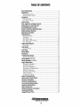
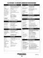
TABLE OF CONTENTS
Parts Identification .....................................................................................2
Introduction ..................................................................................................3
Warranty Procedures .......................................................................... .3
Serial Number Location ...................................................................... 3
Installation ...................................................................................................5
Exhaust System ................................................................................... 7
Raw Water Cooling ............................................................................. 8
Control Panel .............................:...............................................................10
Fuel, Engine Oil and Engine Coolant ................................................... 11
Preparations for Initial Start·Up ..........................................................12
Starting/Stopping Procedure ................................................................13
Break·ln Procedure (Daily Operation).................................................. 14
Safety Shutdown Switches ................................................................... 15
Maintenance Schedule ........................................................................ 16
Cooling System .....................................................................................18
Changing Coolant ............................................................................. 18
Thermostat ........................................................................................ 19
Raw Water Pump .............................................................................. 20
Raw Water Intake Strainer ................................................................20
Heat Exchanger ................................................................................. 21
Engine Lubricating Oil .......................................................................... 22
Oil Change ........................................................................................ 22
Fuel System ..........................................................................................23
Fuel Lift Pump .................................................................................. 23
Glow Plugs ............................................................................................24
Starter Motor.........................................................................................25
Control Box ............................................................................................27
12V DC Control Circuit ..........................................................................28
Battery Specifications ........................................................................ 28
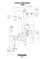
Wiring Diagram (#41990) ...................................................................... 29
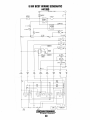
Wiring Schematic (#41990) .................................................................. 30
Engine Adjustments ...................................................................................31
Frequency Adjustment ....................................................................... 31
Fuel Run Solenoid ............................................................................ .31
Drive Belt Adjustments ..................................................................... 32
Torquing the Cylinder Head .............................................................. 32
Engine Compression ......................................................................... .32
Injection Pump Timing ...................................................................... 33
Valve Clearance ................................................................................ .34
Testing Fuel Injectors ........................................................................ 34
Engine Troubleshooting ........................................................................35
Shore Power Transfer Switch ...............................................................37
Generator Information ..........................................................................38
Generator Troubleshooting ...................................................................39
Lay·up and Recommissioning ...............................................................40
Generator Specifications ......................................................................42
Metric Conversions ...............................................................................43
Standard Hardware and Sealants ........................................................45
Torque Specification .............................................................................46
Suggested Spare Partso .........................
n.coo ••.••••••••••••.•••••
47
H
...................
Engines & Generators
1
0 •••
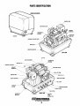
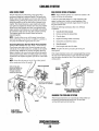
PARTS IDENTIFICATION
.CONTROL BOX
AIR INTAKE FILTER
~
THERMOSTAT
HOUSING
INTERNAL COOLANT PUMP
DRIVE BELT
VIBRATION
MOUNTS~
OIL FILL
I
COOLANT FILL
THERMOSTAT
/HOUSING
PREHEAT SOLENOID~
ZINC---'
EXHAUST
~AIR INTAKE FILTER
MAN\FOlD~"""
.:;ft-'''\'I''---r''--:l7'''H'~I----'-FUEL
CONTROL BOX·
LIFT PUMP
SIDE OIL FILL
t']'l/~%TI:_RAW WATER PUMP
• OIL FILTER
EXHAUS.T
OUTLET
GENERATOR
BACK ENO
Engines & Generators
2
INTRODUCTION
This WESTERBEKE marine generator is a product of
WESTERBEKE'S many years of experience and advanced
technology. We take great pride in the superior durability and
dependable performance of our engines and generators. Thank
you for selecting WESTERBEKE.
This owner's manual contains infonnation and instructions for the
installation, operation, maintenance and service of your generator.
For additional installation information. see WESTERBEKE s
INSTALLATION MANUAL FOR MARINE ENGINES &
GENERATORS, Publication #43268.
In order to get the full use and benefit from your generator,
it is important that you operate and maintain it correctly. This
manual is designed to help you do this. Please read this manual
carefully and observe all the safety precautions throughout
Should your generator require servicing, contact your nearest
WESTERBEKE dealer for assistance.
WESTERBEKE CANNOT BE RESPONSIBLE FOR THE CONTENT
OF SUCH SOFTWARE, MAKES NO WARRANTIES OR
REPRESENTATIONS WITH RESPECT THERETO, INCLUDING
ACCURACY, TIMELINESS OR COMPLETENESS THEREOF AND
WIU IN NO EVENT BE LIABLE FOR ANY TYPE OF DAMAGE OR
INJURY INCURRED IN CONNECTION WITH OR ARISING OUT OF
THE FURNISHING OR USE OF SUCH SOFTWARE.
WESTERBEKE customers should also keep in mind the time
span between printings of WESTERBEKE product software
and the unavoidable existence of earlier WESTERBEKE
manuals. In summation, product software provided with
WESTERBEKE products, whether from WESTERBEKE or
other suppliers, must not and cannot be relied upon exclusively as the definitive authority on the respective product. It
not only makes good sense but is imperative that appropriate
representatives of WESTERBEKE or the supplier in question
be consulted to determine the accuracy and currentness of the
product software being consulted by the customer.
WARRANTY PROCEDURES
YourWESTERBEKE Warranty is included in the documentation
package. If you have not received a customer identification card
registering your warranty 60 days after submitting the warranty
registration form, please contact the factory in writing with model
information, including the unit's serial number and
commission date.
Cu~tomer
Identification Card
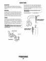
SERIAL NUMBER
Owners may find it convenient to enter the information on the
generator decal and engine identification plate shown below.
These will provide quick references when Seeking technical
information and/or ordering parts.
.- ..
I
,,,,.,,WESTERBEKE
• !
...
~.
~Tiii§ln:t#'3=i
.0
•
, Engines & Generators
-~
MODEL
SPEC
SER.NO.
0•
Customer Identification
Fill in the information for your reference. ~
WESTERBEKE OWNER
MAIN STREET
HOMETOWN, USA
NOTES, CAUTIONS AND WARNINGS
As this manual takes you through the operating pr~edures,
maintenance schedules, and troubleshooting of your marine
engine, critical information will be highlighted by NOTES,
CAUTIONS, and WARNINGS. An explanation follows:
ModelS KW SCOT Ser. #0703-xxxx
E~pires 9/2002 .
NOTE: An operating procedure essential to note.
PRODUCT SOFTWARE
Product software (tech data, parts lists, manuals, brochures and
catalogs) provided from sources other than WESTERBEKE
are not within WESTERBEKE'S CON1ROL.
A CAUTION: Procedures which, if not strictly
observed, can result in the damage or destruction of
your engine.
A WARNING: Procedures which, if not properly followed, can result in personal injury or loss of life. ..
Engines & Generators
3
INTRODUCTION
. Generator Serial Number
SPARES AND ACCESSORIES
Certain spare parts will be needed to support and maintain your
Westerbeke generator when cruising (see SUGGESTED SPARE
PARTS). Often even a simple item such as a proper fuel filter can
be difficult to obtain along the way.
The generator model number and specifications are located on a
decal on the generator housing.
SPECIFICATION ~
MODEL _______ _
RPM __________ _
KW ___________ _
.1
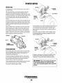
UNDERSTANDING THE DIESEL ENGINE/GENERATOR
The diesel engine closely resembles the gasoline engine, since the
mechanism is essentially the same. The cylinder is arranged
above a closed crankcase. The crankshaft is of the same general
type as on a gasoline engine, and the diesel engine has the same
type of valves, camshaft, piston, connecting rod and
lubricating system.
Therefore, to a great extent, a diesel engine requires the same preventive maintenance as a gasoline engine. The most important
factors are proper ventilation and proper maintenance of the fuel,
lubricating and cooling systems. Fuel filter elements must be
replaced at the time periods specified, and frequent checking for
contaminants (water, sediment, etc.) in the fuel system is also
essential. Another important factor is the consistent use of the
same brand of high detergent diesel lubrication oil designed
specifically for diesel engines.
The diesel engine does differ from the gasoline engine, however,
in its method of handling and firing offuel. The carburetor and
ignition systems are replaced by a single component - the fuel
injection pump - which performs the function of both.
KVA __________ _
VOLTS ________ _
AMPS ________ _
ENG. HP ____ • __
ENG. SER. NO.
GEN. SER. NO.
PF/PHASE ___ _
WIRES ________ _
RATING _______ _
I
INSUL CLASS __
TEMP. RISE ___ _
BATTERY _____ _
PROTECTING YOUR INVESTMENT
C.tD. _________ _
i
i
Care at the factory during assembly and thorough testing have
resulted in a WESTERBEKE generator capable of many
thousands of hours of dependable service. However, the
manufacturer cannot control how or where the generator is
installed in the vessel or the manner in which the unit is operated
and serviced in the field. This is up to the buyer/owner-operator.
~. 'Fill in the information! for reference.
. -
COMPONENT LOCATIONS
Component locations in this manual are referenced from the front
of the engine which is the end at which the raw water pump is
located. Left and right sides are determined as follows: imagine
straddling the engine, facing the front of the engine: the left side
is at your left, the right side is at your right. The left side is the
service side of the generator. The engine and generator controls
are located in an air-cooled air intake/control box.
NOTE: Six important steps to ensure long generator lifo:
•
•
•
•
ORDERING PARTS
Whenever replacement parts are needed, always provide the generator and engine model and serial numbers. You must provide us with
this information so we may properly identify your engine/generator.
In addition, include a complete part description and part number for
each part needed (see the Parts List). Insist upon WESTERBEKE
packaged parts because willfit or generic parts are frequently not
made to the same specifications as original equipment.
•
•
Proper engine and generator installation.
An efficient well-designed exhaust system that includes an
anti-siphon break to prevent water from entering the engine.
Changing the engine oil every 100 operating hours.
Proper maintenance of all engine and generator components
according to the maintenance schedule in this manual.
Use clean, filtered diesel fuel.
Winterize your engine according to the LAY-UP AND
RECOMMISSIONING section in this manual.
Engines & Generators
4
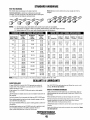
INSTALLATION
I
The following installation instructions cover the Westerbeke 8 Kw
Diesel Generator. Additional general information may be found in
Westerbeke's INSTALLATION MANUALfor MARINE ENGINES
and GENERATORS, Publication #43268.
The following factors should be considered when planning the
installation of your Westerbeke 8 Kw generator:
SPECIAL FUEL RETURN
..i 1/4" HOSE-MALE BARB
"
SUPPLIED
1. Size and weight of the generator.
i SPECIAL FUEl. SUPPLY.
2. Location and mounting surface.
I 1/4" HOSBilALE BARB
, iCONNECTION SUPPLIED
3. Ventilation.
!
~~~
4. Exhaust system.
S. Fuel supply and return.
6. Raw water inlet and outlet.
7. Oil fill and oil drain hose.
',EXHAUST
8. Electrical connections.
2-D (50.8)1.0.
9. Maintenance and service accessibility.
10. Accessories.
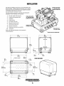
Refer to the following illustrations for the generator's
overall dimensions.
HOLES FOR CONNECTIONS
1 - - - - - 1 , 19.0
;(482.6)
:23.8
1(605.~)
1""1-<~---i25.5~------,>-~1
(33.8)
\(647.n
(
.28 (7. I) 8 HOLES
MOUNT I NG CENTERS
2.6
F-
°
000
° °
'\16.3 in
13.6 in
(412 8 m m ) , ( 3 4 6 . 0 mm)
.L/_
t't:')q
__-_0_o_e-=.o-=-o_o
~0--9!"0_~-=~
-L3.1f"
3.5
(88.9)
.1
21.8.
I (552.5)'
t------125~3~-.- - - - - - I
'(641.4)
1-----1
1~2.6)
SOUND ENCLOSURE
o
o
~13.3
;{77)
Engines & Generators
5
INSTALLATION
LOCATION AND MOUNTING
VENTILATION
A solid, level mounting platform is very important for the proper
operation of your generator. Select a location that will allow
adequate space on all sides for ventilation and servicing. Locate
the generator away from living quarters, and away from bilge
splash and vapors.
The mounting platform may be of wood, metal or fiberglass. It
must be horizontal and should be as small as possible to minimize
vibrations. A low mounting platform is preferred because it will
be stable and easy to build; .a higher mounting platform must be
very sturdy to avoid resonange and vibrations (see illustrations).
Allow for the sufficient intake of cool air for proper engine
combustion and the discharge of the heated air while the generator
is running. Since heated air rises, the intake of cool air should be
directed into the lower area of the generator compartment and the
heated air should be discharged from the upper area of the
compartment.
NOTE: Engine combustion air enters the generator sthrough holes
in the base ofthe enclosure. This area must be kept clear of
obstructions to help insure air entry.
<
....... ;
GENERATOR .
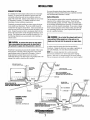
FUEL LINES
Fuel Supply Line
LOW MOUNTING
PLATFORM
(PREFERRED) .
In most installations, the generator would use the same fuel tank
as the vessel's propulsion engine. If this is the case, the fuel supply line to the generator should come from its own pickup in the
common fuel tank and not tee off the supply line to the
propulsion engine.
To assure proper suction, the generator's fuel pump should not be
more than 39" (lm) above the bottom of the fuel pickup tube.
GENERATOR
·HIGH MOUNTiNG
PLATFORM
. '.(NOT PREFERRED)
.
"'"."-.
...
Fuel Re.turn Line
The fuel return line at the fuel tank should extend down to the bottom of the tank in the same manner as the fuel pickup tube. This
must be done in an installation where the fuel tank is located
below the engine's fuel system. This precaution insures against
hard starting due to air displacing fuel siphoning out of the
engine's fuel system through the return line when the generator is
shutdown
If the vibration-dampening mounts furnished with the generator
are not adequate to muffle vibmtion or resonance in an installation
where the mounting surface is not ideal, then adding aplate
between the generator and the boat's mounting platform is a
possible solution. This will also improve the sound insulation. For
this plate, use 1" (2.54cm) thick wood that weighs 22 - 33 lbs
(10 - IS kg), and soft mounts (45 durometer rating) that are
rectangular. Position these mounts so they are on the diagonal
and not aligned with the generator's mounts (see illustration). The
generator's mounts may be turned in any direction. Mount the
plate to the boat's platform, then mount the generator to the plate.
L_-I---+-VI16RATlO~iS
DAMPER
MOUNTS-CAN BE
TURNED ANY DIRECTION
GENERATOR TOP VIEW
Engines & Generators
6
INSTALLATION
EXHAUST SYSTEM
For more information about exhaust system design, see
Westerbeke's INSTALLATION MANUALfor MARINE ENGINES
and GENERATORS, Publication # 43268.
It is important to install a proper exhaust system to avoid engine
flooding. The system must be designed to prevent water from
entering the exhaust line under any sea conditions and at any
angle of the vessel's hull. Exhaust system failures are not covered
by Westerbeke's warranty. The installer should have a basic
knowledge of marine installation requirements.
Westerbeke recommends installing an exhaust system having an
in-line mufller (see illustration). The in-line mufller should be
located below the engine's exhaust elbow. It must accumulate any
water that runs back down the exhaust line after the engine is shut
down. Design the system so there is an adequate drop in the line
between the exhaust elbow and the through-hull discharge end of
the line. The exhaust hose must be certified for marine use. Use
the following illustrations as a general guide when installing an
exhaust system.
Carbon Monoxide
The best protection against carbon monoxide poisoning is a daily
inspection of the complete exhaust system. Check for leaks
around manifolds, gaskets, and welds. Make sure exhaust lines
are not heating surrounding areas excessively. If excessive heat is
present, correct the situation immediately. If you notice a change
in the sound or appearance of the exhaust system, shut down the
unit immediately and have the system inspected and repaired at
once by a qualified mechanic.
A WARNING: 00 not install thl! exhaust outlet near a
swim platform! When people are in the water or in a
dinghy near the boat shut the generator or engine down.
A CAUTION: An exhaust line that is too long and/or
has a poor gradient can cause water to return back to
the generator's engine when the generator is shut off.
A carbon monoxide warning decal has been provided by
Westerbeke. Display this decal near your engine or generator, on
your cabin bulkhead, or in some other prominent location.
NOTE: It is extremely important that a carbon monoxide
detector(s) be installed in your boat sliving and/or sleeping
quarters. Make sure it is manufactured for the marine industry.
They are inexpensive and easily available at your marine supplier.
Westerbeke Corporation presumes that the installer of this marine
diesel generator is familiar with the safeguards a water-cooled
marine exhaust system will provide for the engine. Failure to
design and layout a proper exhaust system can result in
catastrophic damage to the diesel engine, and possibly result in the
sinking of the vessel in which the unit is installed.
).875 in (22.2 mm) OR
in (25.4 mm) 1.0.
!1,~
12 in (30 em)
/
. ABOVE ELBOW:
:MINIIV!.UM ...
"
i1.875 in (47.6 mm)
._~f!------! OR 2.0 In (50.8 mm) 1.0. HOSE
... .... (122 eml MAXIMUM
NOTE: A BACK-PRESSURE TEST CAN
. OETERMINE HOW THIS HEIGHT MAY VARY
112 IN (30 em)
....
ISIPHON-BREAK
.... ((OWNER-SUPPLlEO)
:GENERATOR
!
L"'l~IMUj
i4i1:' (12ii:ml MAXIMUM
~
INOTE: A BACK-PRESSURE TEST CAN·
.
'OETERMINE HOW THIS HEIGHT MAY VARY
EXHAUST SYSTEM
DIAGRAMS
CONTACT YOUR
WESTERBEKE
DEALER FOR
ADDITIONAL INFORMATION
.~
Engines & Generators
7
.. :1.875IN (47.6 mm) OR
i 2.0 IN (50.8 m!ll) 1.0. HOSE
INSTALLATION
RAW WATER COOLING SYSTEM
Raw Water Intake
Siphon-Break
A flush-type through-hull fitting is recommended for the raw
water intake. It should be located on the boat's hull where it will
be below the waterline during all angles of the boat's operation.
See Westerbeke's INSTALLATION MANUAL for MARINE
ENGINES and GENERATORS for complete
installation guidelines.
For installations where the water-injected exhaust elbow is close to
or below the vessel's waterline, provisions must be made to install
a siphon-break in the raw water supply hose to the exhaust elbow.
The siphon-break provides an air vent in the raw water cooling
system to prevent raw water from filling the exhaust system and
the engine's cylinder when the engine is shut down.
A WARNING: Do not use a scoop-type through-hull
A CAUTION: Failure to use a siphon-break when the
fitting for supplying raw water to this generator. A
scoop-type raw water inlet can develop substantial pressure and force water past the raw water pump, flooding
the exhaust system and allowing the water to enter the
engine's cylinder. Damage caused by raw water entry
into the engine's cylinder via the exhaust system is not
covered by Westerbeke's warranty.
exhaust elbow is located at or below the load waterline
will result in raw water damage to the engine and
pOSSible flooding of the boat.
If you have any doubt about the position of the water-injected
exhaust elbow relative to the vessel's waterline under any of the
vessel's various operating conditions or when the vessel is not
under way, install a siphon-break. This precaution is necessary to
protect your engine.
The siphon-break must be installed in the high point of a hose
that is looped a minimum of20 inches (51cm) above the vessel's
waterline. This siphon-break must always be above the
waterline during all angles of vessel operation to prevent,
siphohing. Use a separate hose for this loop, and rim it outside of
the sourtdshield.
I1SIPHON BREAK
I
SIPHON BREAK
AV/,IILABLE FROM YOUR
WESTERBEKE DEALER
Flooding of the exhaust system due to water pressure can also
occur with a flush-type raw water intake on a powerboat that has
its bow up. This pressure can be caused by the boat's decreased
waterline before the boat reaches its final trim, or by the angle of
the boat to the sea surface when it is underway.
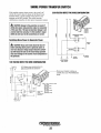
STARTING BATTERY CONNECTIONS
The Westerbeke 18.0 KW Generator is negative grounded. The
generator should be connected to its own 12V starting battery
(125A minimum).
All ground wires should be tightly fastened to the ground bolt
located on the lower left side of the engine below the starter
motor. Make certain the ground terminals are clean.
GROUND BOLT
SIPHON BREAK
DIAGRAM (TYPICAL)
NOTE: A siphon-break requires periodic' inspection and cleaning
to ensure proper operation. Failure to properly maintain a
siphon-break can result in severe engine damage. Consult the
siphon-break manufacturer for a proper maintenance schedule.
Engines & Generators
8
INSTALLATION
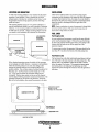
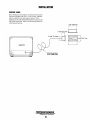
CONTROL PANEL
Mount this plug-in control panel in any desired remote location.
The panel is furnished with 32.8 ft. (10 m) of cable; additional
cable is available if more cable length is required. When
installing, pass the cable though bulkheads by disconnecting the
cable at the control panel. Refer to the following illustration for
control panel dimensions.
5-5/8" (142.9 mm)
\ 1-15/16" (49.2 mm)
213116" (11.4 mm)
1
I"
'I .
J
L
M. "~0""-t..T....
DDD~- 3-11
1
o
I. .
GENERATOR
~MULTI-POLAR
!
CABLE .
32.8FT (10MM) LONG
Engines & Generators
0
.1
.
(9~.7 mm),
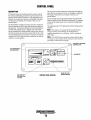
CONTROL PANEL
The oil pressure/coolant temperature warning light (red) lights up
when either the oil pressure is too low or the engine is overheated.
The engine will shut down if it overheats or there is an oil
pressure failure.
DESCRIPTION
This plug-in remote control panel provides the operator with all
the necessary information and controls to use the generator. The
panel has START and STOP buttons, an LED proportional load
indicator, and coolant and oil pressure warning lights.The engine
will shut down automatically if it overheats or there is an oil
pressure failure.
The fuel shutoff solenoid light (yellow) blinks when the START
button is pushed and goes off after the engine starts. If it continues
to blink and the engine doesn't start, it means the starting battery
is too low.
The engine/generator "ON" light (green) will be lit during normal
operation.
The load indicator is designed to avoid an excessive current draw
from the generator due to too many loads having been applied at
the same time. The indicator will begin to show the load after the
first half of the required current is supplied, and it will indicate
that an acceptable load is being provided up to the point where all
the LED's except the last one are lit (5 green LED's are lit). Ifthe
last LED (red) becomes lit, it indicates an overload. The load that
caused this red LED to light up must be switched off to return the
indicator to a normal position.
NOTE: If the engine is not running and the shutoffsolenoid is
energized (yellow LED is blinking), the starting battery is
supplying unneeded power to the engine. Reset by pushing the
STOP button.
NOTE: If the START button is pushed by mistake while the engine
is running, an electrical safoty device protects the starter motor by
preventing its solenoid from energizing.
COOLANT/OIL PRESSURE
WARNING LIGHT
©
LED PROPORTIONAL
LOAD INDICATOR
h
r
100%
HOURMETER
OVER LOAD
PREHEAT
©
FUEL SHUTOFF
SOLENOID LIGHT
(YELLOW)
CONTROL PANEL (REMOTE)
Engines & Generators
10
ENGINE ON LIGHT
RUNNING (GREEN)
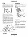
FUEL, ENGINE OIL AND ENGINE COOLANT
DIESEL FUEL
ENGINE COOLANT
Use fuel that meets the requirements or specifications of Class
2-D (ASTM), and has a cetane rating of #45 or better.
Westerbeke recommends a mixture of 50% antifreeze and
50% distilled water. Distilled water is free from the chemicals
that can corrode internal engine surfaces.
Care of the Fuel Supply
The antifreeze performs double duty, as it allows the engine
to run at proper temperatures by transferring heat away from
the engine to the coolant. It also lubricates and protects the
cooling circuit from rust and corrosion. Look for a good
quality antifreeze that contains Supplemental Cooling
Additives (SCAs) that keep the antifreeze chemically
balanced, crucial to long term protection.
Use only clean diesel fuel! The clearance of the components in
your fuel injection pump is very critical; invisible dirt particles
which might pass through the filter can damage these finely
finished parts. It is important to buy clean fuel, and keep it clean.
The best fuel can become unsatisfactory by careless handling or
improper storage facilities. To assure that the fuel going into the
tank for your engine's daily use is clean and pure, the following
practice is advisable:
Purchase a well-known brand of fuel.
Install and regularly service a good, visual-type filter/water
separator between the fuel tank and the engine. Raycor models
220 or 225 are good examples of such spin-on filters.
The distilled water and antifreeze should be premixed before
being poured into the cooling circuit.
NOTE: Use the new environmentally-friendly long lasting
antifreeze that is now available.
Antifreeze mixtures will protect against an unexpected freeze
and they are beneficial to the engine's cooling system. They
retard rust and add to the life of the circulating pump seal.
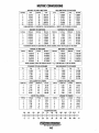
ENGINE OIL
Use a heavy duty engine oil with an API classification of CF or
CG-4. Change the engine oil after an initial 50 hours of break-in
operation, and every 100 hours of operation thereafter. For
recommended oil viscosity, see the following chart:
Operating Temperature
Oil Viscosity
Above 68° F (20° C)
SAE 30, 10W-30 or 15W-40
41° - 68° F (5° - 20° C)
SAE 20 or 1OW-3~
Below 41 ° F (5° C)
SAE 1OW-3~
ANTIFREEZE PROTECTION CHART
Antifreeze concentration
23%
30%
8° F
35%
_4° F
Freezing Temperature
14° F
(-10°C)
50%
-40° F
(-13°C)
(-20°C)
(-40°C)
COOLANT RECOVERY TANK
A coolant recovery tank kit is supplied with each
WESTERBEKE diesel engine.The purpose of this recovery
tank is to allow for engine coolant expansion and contraction
during engine operation, without the loss of coolant and
without introducing air into the cooling system. This kit is
provided and must be installed before operating the engine.
A CAUTION: Do not allow two or more brands of
engine oil to mix. Each brand contains its own additives;
additives of different brands could react in the mixture to
produce properties harmful to your engine.
NOTE: This tank, with its short run of plastic hose, is best
located at or above the level of the engine s manifold but it
can be located below the level of the engine s manifold if the
particular installation makes this necessary.
Engines & Generators
11
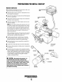
PREPARATIONS FOR INITIAL START-UP
PRESTART INSPECTION
Before starting your generator for the first time or after a prolonged layoff, check the following items:
• Check the engine oil level: add oil to maintain the level at
the full mark on the dipstick.
• Check the fuel supply and examine the fuel filter/separator
bowls for contaminants.
MANIFOLD PRESSURE
CAP
• Check the DC electrical system. Inspect wire connections
and battery cable connections.
• Check the coolant level in both the plastic recovery tank
and at the manifold.
NOTE: After the initial running of the generator, the air in
the engine s cooling system will be purged to the coolant
recovery tank. Open the air bleed petcock to ensure that
the cooling system is purged of air. After shutdown and
after the engine has cooled, the coolant from the recovery
tank will be drawn into the engine s cooling system to
replace the purged air.
Before subsequent operation of the generator, the engines
manifold should be topped off, and the coolant recovery
tank may need to be filled to the MAX level.
• Visually examine the unit. Look for loose or missing
parts, disconnected wires, unattached hoses, and check
threaded connections. Search for any gasoline leaks.
• Check load leads for correct connections as specified in
the wiring diagrams.
USE THE MOST
CONVENIENT
OIL FILL
• Examine the air inlet and outlet for air flow obstructions.
• Be sure no other generator or utility power is connected to
the load lines.
• Be sure that in power systems with a neutral line that the
neutral is properly grounded (or ungrounded) as the system
requires, and that generator neutral is properly connected
to the load neutral. In single phase systems an incomplete
dr open neutral can supply the wrong line-to-neutral
voltage on unbalanced loads.
A CAUTION:
When starting the generator.. it is
recommended that all AC loads, especiallyJarge
motors, be switched OFF until the engine has come up
to speed and, in cold climates, starts to warm up. This
precaution will prevent damage caused by unanticipated operation of the AC machinery and will prevent a
cold engine from stalling.
ADD OIL
'OIL COOLER
SPIN ON
OIL FILTER
Engines & Generators
12
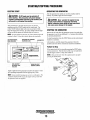
STARTING/STOPPING PROCEDURE
OPERATING THE GENERATOR
ELECTRIC START
After the generator has started, run it with a medium load for
warmup. Ifpossible, apply the load in stages.
A CAUTION: All AC loads must be switched off
before starting. This precaution will prevent damage
caused by unanticipated operation of AC machinery and
will prevent a cold engine from stalling.
A CAUTION: Never operate the engine for long
periods of time without an amperage load being
applied, otherwise carbon build-up may occur which
can cause severe damage to the engine.
This generator has a 12 VDC electric starter. To start the
generator, push the START button on the control panel. The
yellow START indicator light will come on and start to blink:.
Once the engine fires and runs, the yellow START indicator light
will go out and the green run indicator light will come on.
NOTE: If a start attempt is ~borted, the yellow indicator light will
continue to blink To reset the circuit, depress the stop button.
I
II
LED PROPORTIONAL ..
LOAD INDICATOR
@
leOOLANT/OiL PRESSUR~
[WARNING LIGHT
STOPPING THE GENERATOR
.JHOURMETER
@
Remove the AC loads from the generator one at a time and allow
the generator to run for an additional 3 to 5 minutes (this stabilizes
its operating temperature).
• To stop the generator, press the STOP button on the control panel;
\ shutdown is automatic.
After shutdown, carefully inspect the generator. Check for
possible leaks from all the connections inside the soundshield.
Failure to Stop
If the engine should fail to stop after pressing the STOP button,
use the control lever: Push the lever all the way over and hold it
until the engine comes to a stop, then release it.
NOTE: Only use this lever when the engine doesn't stop after
pressing the STOP button.
@
Apply a light load to the generator and allow the engine to warm
up to operating temperature before applying heavy loads
NOTE: Some unstable running may occur in a cold engine. This
condition should smooth out as the engine warms up and when
the generator loads are applied.
.
Engines & Generators
·13
BREAK-IN PROCEDURE/DAILY OPERATION
NOTE: Some unstable running may occur in a cold engine.
BREAK-IN PROCEDURE
After the generator has been started, check for proper operation and then encourage a fast wann-up. Run the generator
between 20% to 60% of full load for the fIrst 10 hours.
This condition should abate as normal operating temperature
is reached and loads are applied.
A CAUTION:
00 not operate the generator for long
periods of time without a load being placed on the
generator.
A CAUTION:
00 not attempt to break-in your generator by running without a load.
After the fIrst 10 hours of the generators' operation, the load
can be increased to the full-load rated output; then periodically vary the load.
STOPPING THE GENERATOR
Remove the major AC loads from the generator one at a time.
Allow the generator to run for a few minutes to stabilize the
operating temperature and press the STOP switch down, (see
CONTROL PANELS).
Avoid overload at all times. An overload is signaled by a
smoky exhaust with reduced output voltage and frequency.
Monitor the current being drawn from the generator and keep
it within the generators' rating. Since the generator operates
at 3600 rpm to produce 60 hertz, or at 3000 to produce 50
hertz, control of the generator's engine break-in is governed
by the current drawn from the generator.
NOTE: After the first 50 hours of generator operation check
the maintenance schedule for the 50 hour service check.
GENERATOR ADJUSTMENTS
Once the generator has been placed in operation, there may
be governor adjustments required for engine speed (hertz)
during the engine's break-in period (fIrst 50 hours) or after
this period (see ENGINE SPEED (HER1Z) ADJUSTMENT
under ENGINE ADJUSTMENTS. A no-load voltage adjustment may also be required in conjunction with the engine's
speed adjustment (see GENERATIOR INFORMATION).
To protect against unintentional overloading of the generator,
the generator's output leads should be routed through a circuit breaker that is rated at the rated output of the generator.
NOTE: Be aware of motor starting loads and the high
current drawn required for starting motors. This starting
amperage drawn can be 3 to 5 times normal running amperage. See GENERATOR INFORMATION in this manual.
CHECK LIST
Follow this checklist each day before starting your generator.
• Record the hourmeter reading in your log (engine hours
relate to the maintenance schedule).
• Visually inspect the engil!e for fuel, oil, or water leaks.
• Check the oil level (dipstick).
• Check the coolant level in the coolant recovery tank.
• Check your fuel supply.
• Check the starting batteries (weekly).
• Check the drive belt for wear and proper tension (weekly).
• Check for abnormal noise such as knocking, vibration and
blow-back sounds.
• Confmn exhaust smoke:
When the engine is cold - White Smoke.
When the engine is wann - almost Smokeless.
When the engine is overloaded - some Black Smoke.
Engines &.Generators
14
SAFETY SHUTDOWN SWITCHES
SAFETY SHUTDOWN SWITCHES
Low Oil Pressure Switch
The generator is protected by three automatic shutdown
switches. Should shutdown occur, do not attempt to restart
without finding and correcting the cause. Refer to the
ENGINE TROUBLESHOOTING section of this manual.
A low oil pressure shutdown switch is located off the
engine's oil gallery. Normally open in a static state, this
switch's sensor monitors the engine's oil pressure. Should
the engine's oil pressure fall to 5-10 psi, this switch will
open interrupting the DC voltage to the fuel solenoid on the
injection pump, thereby shutting off the engine.
The following is a description of these automatic shutdown
switches:
High Water Temperature Switch
A high water temperature switch is located on the thermostat
housing. Normally closed, this switch, should the fresh water
coolant's operating temperature reach approximately 210°F
(99°C), will open and interrupt the DC voltage to the fuel
solenoid on the injection pump, thereby shutting off the
engine. This switch resets at 19SOF (107°C).
OIL PRESSURE SWITCH
LOCATED AT THE FRONT
. OF THE ENGINE NEXT TO
THE CRANKSHAFT PULLEY
Engine Circuit Breaker
The generator's engine is protected by an engine mounted
I manual reset circuit breaker (20 amps DC). Excessive current
draw or electrical overload anywhere in the instrument panel
wiring or engine wiring will cause the breaker to trip. In this
event most generators will shut down because the opened
breaker disconnects the fuel supply. If this should occur,
; check and repair the source of the problem. After repairing
the fault, reset the breaker and restart the generator.
!
Engines & Generators
15
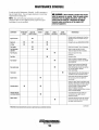
MAINTENANCE SCHEDULE
In order to use this Maintenance Schedule, it will be necessary to
log your engine hours. Use your engine hourmeter or record your
engine hours by running time.
A WARNING:
Never attempt to perform any service
while the generator is running. Wear the proper safety
equipment such as goggles and gloves, and use the
correct tools for each job. Disconnect the battery
terminals when servicing any of the engine's DC
electrical equipment.
NOTE: Many of the following maintenance procedures are
simple but others are more difficult and may require the expert
knowledge ofa service mechanic.
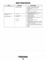
FREQUENCY
COMPONENT
AFTER FIRST
50 HRS
Engine oil level
Engine oil
Oil filler
Fuel supply
•
•
DAILY OR
EVERY 8 HOURS
WEEKLY
EVERY
600 HOURS
•
•
•
Check the fuel supply. Top up if necessary.
Check for water and dirt in the fuel.
Drain and replace the filter if necessary.
•
Change the filter.
Fuel injector'
Raw water pump
•
Check and adjust the injection opening
pressure and spray condition (see ENGINE
ADJUSTMENTS).
•
Remove the pump cover and inspect the
impeller, gasket, cam and cover for wear.
Check the bearings and seals (the shaft can
turn, but not wobble). Lubricate
when reassembling .
•
Thermostat
Starling batteries
and house batterie
Clean and inspect the wiring
connection.
•
Fuel filler
Engine hoses
•
MAINTENANCE
Change the oil: see LUBRICATION SYSTEM
Fuel lift pump
Exhaust system'
EVERY
2100 HOURS
Oil level should be between the full and low
indicating marks on the dipstick. Top up if
necessary.
•
•
•
•
Fuellilter/water
separator
EVERY
100 HOURS
Check the functioning of the thermostat; see
THERMOSTAT under COOLING SYSTEM.
•
Hoses should be hard and tight. Replace if
soft and spongy. Check and tighten all
hose clamps.
•
Inspect for leaks. Check the anti-siphon valve
operation. Check that all connections are tight.
Check the exhaust elbow for carbon and/or
corrosion buildup on inside passages;
clean and replace as necessary.
Warning: A defective exhaust elbow can cause
carbon monoxide leakage!
•
Check electrolyte levels and make sure
connections are very tight. Clean off
excessive corrosion.
Starler motor'
•
'Westerbeke recommends that this service be performed by an authorized mechanic.
Engines & Generators
16
Check the solenoid and motor for corrosion.
Remove and lubricate. Clean and lubricate
the starter motor pinion drive.
(continued)
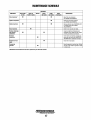
MAINTENANCE SCHEDULE
FREQUENCY
COMPONENT
Valve clearances'
AFTER FIRST
50 HRS
DAILY OR
EVERY 8 HOURS
WEEKLY
EVERY
100 HOURS
•
•
•
•
Cylinder compression
Cylinder head bolts
•
•
Visual inspection
Hardware fastenings
and electrical
connections
Generator
connections
EVERY
2100 HOURS
MAINTENANCE
Adjust the valve clearances;
(see ENGINE ADJUSTMENTS}.
Check the compression pressure
(see ENGINE ADJUSTMENTS}.
Retorque the bolts (see TIGHTENING THE
CYLINDER HEAD under ENGINE
ADJUSTMENTS.)
Check for oil, fuel and water leaks.
Inspect and tighten all fastenings and
accessible screws, bolts and nuts. Inspect
all wiring and electrical connections.
•
•
Check that AC connections are clean and
secure with no chafing. See GENERATOR
INFORMATION for additional information.
•
•
Generator no-load
speed
Cleaning the
generator
EVERY
600 HOURS
Check the no-load speed.
Keep the generator's surface clean. Surface
dirt and oil will inhibit the generator's ability
to remain cool.
•
'Westerbeke recommends that this service be performed by an authorized mechanic.
Engines & Generators
17
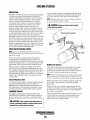
COOLING SYSTEM
DESCRIPTION
Drain the engine coolant by loosening the drain plug on the
engine block and opening the manifold pressure cap. Flush
, the system with fresh water, then start the refill process.
Westerbeke marine diesel engines are designed and equipped
for fresh water cooling. Heat produced in the engine by
combustion and friction is transferred to fresh water coolant
which circulates throughout the engine. This circulating
fresh water coolant cools the engine block, its internal
moving parts, and the engine oil. The heat is transferred
externally from the fresh water coolant to raw water by
means of a heat exchanger, similar in function to an
automotive radiator. Raw water flows through the tubes of
the heat exchanger while fresh water coolant flows around _
the tubes; engine heat transfern;Ci to the fresh water coolant
is conducted through the tubewail;,-t:o the raw water which is
then pumped into the exhaust system where finally it is
discharged overboard. In other words, the engine is cooled by
fresh water coolant, this coolant is cooled by raw water, and
the raw water carries the transferred heat overboard through
the exhaust system. The fresh water coolant and raw water
circuits are independent of each other. Using only fresh water
coolant within the engine allows the cooling water passages
to stay clean and free from harmful deposits.
NOTE: The drain petcock on the heat exchanger should also
be used to help drain engine coolant.
A WARNING: Beware of the hot engine coolant.
Wear protective gloves.
/'
• MANIFOLD/HEAT EXCHANGER
COOLANTDRAIN
FRESH WATER COOLING CIRCUIT
NOTE: Refer to the ENGINE COOLANT section for the
recommended antifreeze and water mixture to be used as the
fresh water coolant.
Fresh water coolant is pumped through the engine by a
circulating pump, absorbing heat from the engine. The
coolant then passes through the thermostat into the manifold,
to the heat exchanger where it is cooled, and returned to the
engine block via the suction side of the circulating pump.
When the engine is started cold, external coolant flow is
prevented by the closed thermostat (although some coolant
flow is bypassed around the thermostat to prevent the exhaust
manifold from overheating). As the engine warms up, the
thermostat gradually opens, allowing full flow of the engine's
coolant to flow unrestricted to the external portion of the
cooling system.
Refilling the Coolant
. After replacing the engine block drain plug, close the heat
exchanger'S coolant drain. Then pour clean, premixed
coolant into the manifold and when the coolant is visable in
the manifold, start the engine and run it at slow idle.
NOTE: Open the air-bleed petcock on the thermostat housing.
When a steady flow of coolant appears at the petcock, close
the petcock and fill the system until the manifold remains full.
Coolant Recovery Tank
· Monitor the coolant in the manifold and add as needed. Fill
· the manifold to the filler neck and install the manifold
pressure cap.
A coolant recovery tank allows for engine coolant expansion
and contraction during engine operation, without any
significant loss of coolant and without introducing air into
the cooling system. This tank should be located at or above
the engine manifold level and should be easily accessible.
·Remove the cap on the coolant recovery tank and fill with
coolant mix to halfway between LOW and MAX and replace
the cap. Run the engine and observe the coolant expansion
flow into the recovery tank.
CHANGING COOLANT
After checking for leaks, stop the engine and allow it to cool.
·Coolant should draw back into the cooling system as the
·engine cools down. Add coolant to the recovery tank if
:needed. Clean up any spilled coolant.
The engine's coolant must be changed according to the
MAINTENANCE SCHEDULE. If the coolant is allowed to
become contaminated, it can lead to overheating problems.
A CAUTION: Proper cooling system maintenance is
critical; a substantial number of engine failures can be
traced back to cooling system corrosion.
Engines & Generators
18
COOLING SYSTEM
NOTE: Periodically check the condition of the manifold
pressure cap. Ensure that the upper and lower rubber seals
are in good condition and check that the vacuum valve opens
and closes tightly. Carry a spare <:ap.
COOLANT TEMPERATURE SWITCH
The coolant temperature switch is located near the thermostat
housing (see illustration). If the coolant's operating temperature
reaches approximately 2100 F (99 0 C) this switch will light up the
red (LED) engine overheat indicator on the control panel and shut
down the generator.
AIR COOLING
Cooling air is continuously circulated (by air hose) thru the control panel and around to the engine air intake where it passes thru
a filter into the engine.
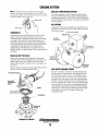
INSPECT SEAL
THERMOSTAT
A thermostat, located near the manifold at the front of th~
engine, controls the coolant temperature as the coolant
continuously flows through the closed cooling circuit. When
the engine is first started, the closed thermostat prevents
coolant from flowing (some coolant is by-passed through a
hole in the thermostat to prevent the exhaust manifold from
overheating). As the engine warms up, the thermostat
gradually opens. The thermostat is accessible and can be
checked, cleaned, or replaced easily. Carry a spare thermostat
and gasket.
INCOMING
• COOLING AIR
."
.
. V·:: ~FROM RAW
}·TrVATER PUMP.
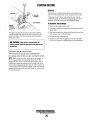
Replacing the Thermostat
Remove the cap screws and disassemble the thermostat
housing as shown. When installing the new thermostat and
gasket, apply a thin coat of sealant on both sides of the
gasket before pressing it into place. Do not over-tighten the
cap screws.
Run the engine and check for normal temperatures and that
there are no leaks at the thermostat housing.
RAW WATER COOLING CIRCUIT~
The raw water flow is created by a positive displacement
impeller pump. This pump draws water directly from the
raw water source (ocean, lake, or river) through a hose to
the water strainer. The raw water passes from the strainer
through the raw water pump to the water cooled generator
and then to the heat exchanger. The raw water passes thru
the heat exchanger tubes where it cools the circulating fresh
water (coolant). The raw water is then discharged into the
water-injected exhaust elbow, mixing with and cooling the
exhaust gasses. This mixture of exhaust gas and raw water
is discharged overboard by the engine's exhaust gas
discharge pressure.
HIGH WATER
TEMPERATURE .>-------lS~::.;:..~
SWITCH
!THERMOSTAT ASSEMBLY
Engines ~ Generators
19
COOLING SYSTEM
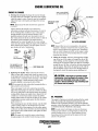
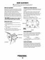
RAW WATER PUMP
RAW WATER INTAKE STRAINER
The raw water pump is a self-piiming, rotary pump with a
non-ferrous housing and a neoprene impeller. The impeller has
flexible vanes which wipe against a curved cam plate within the
impeller housing, producing the pumping action. On no account
should this pump be run dry as water acts as a lubricant for the
impeller. There should always be a spare impeller and impeller
cover gasket (an impeller kit) onboard. Raw water pump impeller
failures occur when lubricant (raw water) is not present during
engine operation. Such failures are not warrantable and qperators
are cautioned to make sure raw water flow is present at start-up.
The neoprene impeller has a limited lifetime and must be
inspected regularly.
NOTE: Always install the strainer at or below the waterline so the
strainer will always be self-priming.
A clean raw water intake strainer is a vital component of the
engine's cooling system. Include a visual inspection of this
strainer when making your periodic engine check. The water in
the glass should be clear.
Perform the following maintenance after every 100 hours
of operation:
I: Close the raw water seacock.
2. Remove and clean the strainer filter.
3. Clean the glass.
4. Replace the sealing washer if necessary.
5. Reassemble and install the strainer.
6. QRen the seacock.
7. Run the engine and check for leaks.
NOTE: Also follow the above procedure after having run
hard aground.
NOTE: Should a failure occur with the pump s internal parts
(seals and bearings), it may be more cost effoctive to purchase a
new pump and rebuild the original pump as a spare.
Inspecting/Changing the Raw Water Pump Impeller
Close the raw water intake valve. Remove the pump cover and,
with the aid of two small screwdrivers, carefully pry the impeller
out of the pump. Install the new impeller and gasket. Move the
blades to conform to the curved cam plate and push the impeller
into the pump's housing. When assembling, apply a thin coating
of lubricant to the impeller and gasket. Open the raw water intake
valve.
NOTE: Never allow the pump tOntil dry. Even-a-inortperiod
of dry running may destroy the impeller.·
-
If the engine temperature seems to be running higher than normal,
the cause may be that silt, leaves or grass may have been caught
up in the strainer, slowing the flow of raw water through the
cooling system.
I
IMPELLER BLADES
i SHOULD BE INSPECTED.
BEND EACH BLADE AT
ITS BASE. LOOK FOR
. CRACKS OR SPLITTING.
.~
~
IMPELLER PN#33636
SEALlN.G
....
WASHER~-
STRAINER
TYPICAL INTAKE STRAINER
(OWNER INSTALLED)
DRAINING THE COOLING SYSTEM
When freezing temperatures are expected, the cooling system can
be drained by unscrewing the pump cover. The raw water
will then flush back down the inlet line.
RAW WATER
PUMP ASSEMBLY
Engines & Generators
20
COOLING SYSTEM
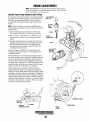
Zinc Anode
Heat Exchanger Service
A zinc anode, or pencil, is located in the raw water cooling
circuit within the heat exchanger. The purpose of having
zinc anodes is to sacrifice them to electrolysis action taking
place in the raw water cooling circuit, thereby reducing the
effects of electrolysis on other components of the system.
The condition of the zinc anode should be checked monthly
and the anode cleaned or replaced as required. Spare anodes
should be carried on board .
After approximately 1000 hours of operation, remove, clean
and pressure test the engine's heat exchanger. (A local automotive radiator shop should be able to clean and test the heat
exchanger.)
NOTE: Operating in silty and/or tropical waters may require
that a heat exchanger cleaning be performed more often than
every 1000 hours.
. ZINC ANODES
NEW
REPLACE
CLEAN AND
REUSE
NOTE: Electrolysis action is the result of each particular
installation and vessel location; not that of the engine.
If the zinc anodes need replacement, hold the hex boss into
which the zinc anode is threaded with a wrench while loosening the anode with another wrench. This prevents the hex
boss from possibly tearing off the exchanger shell. After
removing the zinc, note the condition of it. If the zinc is in
poor condition, there are probably a lot of zinc flakes within
the exchanger. Remove the end of the heat exchanger and
clean the inside of all zinc debris. Always have a spare heat
exchanger end gasket in case the present one becomes damaged when removing the end cover. Replace the gasket (refer
to your engine model's heat exchanger end gasket part number), O-ring and cover, and 'install a new zinc anode.
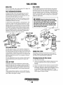
INTAKE
SILENCER
,/
/
/
AIR
AIR INTAKE/SILENCER
Description
A marine diesel engine running at high speed will typically
consume more than 6,000 cubic feet of air per hour. Not only
must the engine room be well ventilated, the air flow into the
engine must be umestricted.
NOTE: The threads of the zinc anodes are pipe threads and
do not require sealant. Sealant should not be used as it may
insulate the zinc from the metal of the heat exchanger housing preventing electrolysis action on the zinc.
Air Filter
The air filter cartridge prevents engine room dust and dirt
from entering the engine, it also extends engine life, and
quiets the engine.
· Maintenance
, The filter should be cleaned every 100 operating hours. Tap
· the cartridge on a flat surface to dislodge loose dirt or clean
· off with compressed air. If the cartridge is badly contaminated or oily, replace it.
ZINC ANODE
iDa NOT USE SEALANT
fAN OUT DEBRIS
HEAT EXCHANGER
Engines & Generators
21
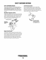
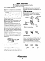
ENGINE LUBRICATING OIL
ENGINE OIL CHANGE
APPLY CLEAN ENGINE
OIL WHEN INSTALLING
1. Draining the oil sump. Discharge the used oil through
the sump drain hose (attached to the front of the engine)
while the engine is warm. Drain the used oil completely,
replace the hose in its bracket and replace the end cap
I
SPIN ON OIL
securely.
PN#36918
NOTE: Thread size for the lube oil drain hose capped end
is II4NFT.
Always observe the used oil as it is removed. A
yellow/gray emulsion indicates the presence of water in
the oil. Although this condition is rare, it does require
prompt attention to prevent serious damage. Call a
qualified mechanic should water be present in the oil.
TURN ON REAL TiGHT,
Raw water present in the oil can be the result of a fault in
i BYHAND
the exhaust system attached to the engine and/or a
siphoning of raw water through the raw water cooling
I_OIL FILTER ASSEMBLY
circuit into the exhaust, filling the engine. This problem is
often caused by the absence of an anti-siphon valve, its
NOTE: Generic filters are not recommended, as the material
poor location or lack of maintenance.
standards or diameters ofimportant items on generic parts
might be entirely difforent from genuine parts. Immediately
i8MM
/11116 INCH
after an oil filter change and oil fill, run the engine to make
;SOCKET .
sure the oil pressure is normal and that there are no leaks
t,
around the new oil filter.
\114" NFT
3. Filling the oil sump. Add new oil through the oil filler
!FOR EXTENSION~
cap on the top of the engine or through the side oil fill.
; I'
After refilling, run the engine for a few moments while
checking the oil pressure. Make sure there is no leakage
around the new oil filter or from the oil drain system, and
THE WARMFolJlL CAN
ALSO BE PUMPED UP ,
stop the engine. Then check the quantity of oil with the
THRU THE DRAIN HOSE
lube oil dipstick. Fill to, but not over the high mark on
the dipstick, should the engine require additional oil.
I
])
2. Replacing the oilfilter. When-removing the used oil
filter, you may find it helpful and cleaner to punch a hole
in the upper and lower portion of the old filter to drain the
oil from it into a container before removing it. This helps
to lessen spillage. A small automotive filter wrench
should be helpful in removing the old oil filter.
NOTE: Do not punch this hole without first loosening the filter to
make certain it can be removed.
Place some paper towels and a plastic bag around the
filter when unscrewing it to catch any oil left in the filter.
(Oil or any other fluid on the engine reduces the engine's
cooling ability. Keep your engine clean.) Inspect the old
oil filter as it is removed to make sure that the rubber
sealing gasket comes off with the old filter. If this rubber
sealing gasket remains sealed against the filter bracket,
gently remove it.
When installing the new oil filter element, wipe the filter
gasket's sealing surface on the bracket free of oil and
apply a thin coat of clean engine oil to the rubber gasket
on the new oil filter. Screw the filter onto the threaded oil
filter nipple on the oil filter brac,ket, and tighten the filter
firmly by hand.
NOTE: The engine oil is cooled by engine coolant flowing
through passages in the oil filter bracket housing assembly.
A
CAUTION: Used engine oil contains harmful
contaminates. Avoid prolonged skin contact. Clean
skin and nails thoroughly using soap and water.
Launder or discard clothing or rags containing used
oil. Discard used oil properly.
OIL PRESSURE
The engine's oil pressure,is constantly monitored by the control
panel. The red light will illuminate and the generator will
shutdown if the oil pressure fall below 5 psi. Do not restart the
generator without checking the oil and finding the problem. Refer
to TESTING THE OIL PRESSURE in this manual.
NOTE: A newly started, cold engine can have an oil pressure
reading upwards of 60 psi. A warmed engine can have an oil
pressure reading as low as 35 psi. These readings will vary
depending upon the temperature, ojtheengin;e and the load '
placed on the generator.
Engines & Generators
22
FUEL SYSTEM
DIESEL FUEL
FUEL FILTERS
Use No.2 diesel fuel with a cetane rating of 45 or higher. Do
not use kerosene or home heating fuel.
The fuel injection pump and the fuel injectors are precisely
manufactured and they must receive clean diesel fuel, free
from water and dirt. To ensure this flow of clean fuel, the fuel
must pass through at least two fuel filters, a fuel filter/water
separator and the engine's spin-on fuel filter. Visually inspect,
clean, and change these,filters according to the maintenance
schedule in this manual.
FUEL FILTER/WATER SEPARATOR
A primary fuel filter of the water separating type must be
installed between the fuel tank and the engine to remove
water and other contaminants from the fuel before they can
be carried to the fuel system on the engine.
Most installers include a fuel filter/water separator with the
installation package as they are aware of the problems that
contaminants in the fuel can cause.
A typical fuel filler/water separator is illustrated below. This
is the Rayeor Model 500 MA. Keep in mind that if a water
separator type filter is not installed between the fuel supply
tank and engine-mounted fuet system, any water in the fuel
will affect the fuel pump, engine filter, and injection equipment. The owner/operator is responsible for making certain
the fuel reaching the engine's injection equipment is free of
impurities. This process is accomplished by installing and
maintaining a proper fuel filter/water separator.
t(t1 ~'11
-~
A
WARNING: Shut off the fuel valve at the tank
when servicing the fuel system. Take care in catching
any fuel that may spill. DO NOT allow any smoking.
open "ames or other sources of fire near the fuel system when servic!ng. Ensure proper ventilation exists
when servicing the fuel system.
: FUEL LIFT PUMP
TO FUEL
i FILTER,
Q.,:;:~i;;-:-r-----i'DRAIN
The fuel injection pump is a very important component of
the diesel engine, requiring the utmost care in handling. The
fuel injection pump has been thoroughly bench-tested and the
owner-operator is cautioned not to attempt to service it. Ifit
requires servicing, remove it and take it to an authorized fuel
injection pump service facility. Do not attempt to disassemble and repair it.
ENGINE FUEL FILTER
I
IBOWL,
,
Periodically check the fuel connections and the bowl for
leakage. Replace the filter element after the first 50 hours
then follow the MAINTENANCE SCHEDULE.
The only adjustment the servicing mechanic should make to
the fuel injection pump is the adjustment for engine idle
speed.
Changing/cleaning the filter element
1. Shut off the fuel supply.
2. Unscrew the retainer ring that holds the filter bowl to the
housing and allow the bowl to come away from the
housing,
FUEL LIFT PUMP
Periodically check the fuel connections to and out of the
pump and make sure that no leakage is present and that the
fittings are tight and secure. The DC ground connection at
one of the pump's mounting bolts should be clean and well
secured by the mounting bolt to ensure proper pump operations.
When energized thru the preheat circuit, the fuel lift pump
will purge air from the fuel system and provide a continuous
flow of fuel as the engine is running.
3. Remove and replace the filter element and clean the bowl.
4. Replace the sealing "0" ring and reassemble the bowl to
the housing. Thread the retainer ring OR carefully so as not
to cross thread. When retainer contacts the "0" ring,
tighten 114 - 112 turns by hand. Open the fuel supply.and
run the engine to inspect for leaks.
Engines & Generators
23
GLOW PLUGS
DESCRIPTION
The glow plugs are wired through the preheat solenoid.
When the START button is pressed at the control panel this
solenoid should "click" on and the glow plugs should begin
to get hot.
Re-install the plugs in the engine and test them again. The
plugs should get very hot (at the terminal end) within 20 to
25 seconds. If the plugs don't heat up quickly, check for a
short circuit. When reinstalling the glow plugs, use anti-seize
compound on the threads.
A WARNING: 00 not keep a glow plug on for more
INSPECTION
To inspect the plug, remove the electrical terminal connections, then unscrew or unclamp each plug from the cylinder
head. Thoroughly clean each plug's tip and threads with a
soft brush and cleaning solution to remove all the carbon and
oil deposits. While cleaning, examine the tip for wear and
bum erosion; if it has eroded too much, replace the plug.
than 30 seconds.
Glow Plug Tightening Torque
1.5 - 2.0 Ib-II (10-14 kg-m)
TERMINAL
,ENO
TESTING
An accurate way to test glow plugs is with an ohmmeter.
Touch one prod to the glow plug's wire connection, and the
other to the body of the glow plug, as shown. A good glow
plug will have a 1.0 - 1.5 ohm resistance. This method can be
used with the plug in or out of the engine. You can also use
an ammeter to test the power drain (8 - 9 amps per plug).
TESTING A GLOW PLUG
. WITH AN OHMMETER
. TIP
A WARNING: These glow plugs win become very hot
to the touch. Be careful not to burn your fingers when
testing the plugs.
. TESTING A GLOW PLUG
, USING A TEST LIGHT
GLOW PLUG
FUEL INJECTOR
Engines & Generators
24
STARTER MOTOR
DESCRIPTION
The starting system includes the battery, starter motor, solenoid,
and starter button.
When the starter button on the instrument panel is depressed,
current flows and energizes the starter's solenoid coil. The
energized coil becomes an electromilgnet, which pulls the plunger
into the coil, and closes a set of contacts which allow high current
to reach the starter motor. At the same time, the plunger also
serves to push that starter pinion to mesh with the teeth on the
flywheel.
IGNITION',
TERMINAL\
'fOcoNfifoi.
PANEL
,T() prevent damage
to the starter motor when the engine starts, the
pinion gear incorporates an ,over-running (one-way) clutch which
is splined tothe$J:ter armature shaft. The rotation of the rutming
engine may speed ti1erotation of the pinion but not the starter
motor itself
.
To test the ignition circuit, locate the ignition(s) terminal (it is one
of the small tenninal studs and is wired to the ignition circuit).
Use a screwdriver, don't touch the blade, to jump from that
ignition terminal to the positive battery connection terminal on
the solenoid.
H the starter cranks, the fault lies with the ignition circuit
H the solenoid clicks but nothing else happens, the starter
motor is probably faulty.
Once the started button is released, the cUrrent flow ceases, stopping the activation of the solenoid. The plunger is pulled out of
contact with the battery-to-start cables by a coil spring, and the
flow of electricity is interrupted to the starter. This weakens the
,,' .magnetic fields and the starter ceases its rotation. As the solenoid
plunger is released, its movement also pulls the starter drive gear
from its engagement with the engine flywheel.
!TERMINALS
~
~r"'r~------J(+)
TYPICAL
POSITIVE
L TERMINAL'
STARTER MOTOR
IGNITION
TERMINAL
TROUBLESHOOTING
TOCONTROD
PANEL
Prior to testing, make certain the ships batteries are at full charge
and that the starting system wiring connections (terminals) are
clean and tight. Pay particular attention to the ground wire
connections on the engine block
To check the wiring, try cranking the starter for a few seconds,
never more than 10 seconds at a time, then run your hand along
the wires and terminals looking for warm spots that indicate
resistance. Repair or replace any trouble spots.
Using a multimeter, test the voltage between the positive tenninal
stud on the start solenoid and the engine block (ground).
H you read 12 volts, the starter is faulty.
~
Unothing at all happens the solenoid isn't getting current
Check the battery isolation switch and inspect the wiring
connections. It is also possible that the solenoid is defective.
A WARNING: There will be arching and sparks will
fly when jumping terminals. Be certain the engine
space is free of potentially explosive fumes, especially
gasoline.
Engines & Generators
25
STARTER MOTOR
SERVICE
Westerbeke uses a standard marine starter motor which can be
serviced or rebuilt at any starter motor automotive service center.
If replacing the starter motor, make certain the new motor is
certified for marine use. Automotive starters do not meet USCG
standards. If in dO)lbt, contact your WESTERBEKE dealer.
\(+) POSITIVE
~.-\\ TERMINAL
~"------1: (M)
TERMINAL
TO REMOVE FOR SERVICE
IGNITION
TERMINAL
TO CONTROL
PANEL
1. Disconnect the negative battery cable.
. 2. If necessary, remove any components to gain full access to the
starter motor.
3. Label and disconnect the wiring from the starter. (Do not allow
wires to touch, tape over the terminals).
Test again by jumping the two large terminal studs. Hold the
screwdriver blade firmly between the studs. Do not allow the
screwdriver blade to touch the solenoid or starter casing, this
would cause a short.
4. Remove the starter mounting bolts.
5. Remove the starter from the engine. In some cases the starter
will have to be turned to a different angle to clear obstructions.
A WARNING: There will be arching as the full
starting current should be flowing thru the blade of the
screwdriver.
If the starter spins, the solenoid is faulty.
If the starter fails to spin, the motor is probably faulty.
If no arching occurred. There is ,no juice reaching the solenoid.
NOTE: Starter motors are either inertia type or pre-engaged. In
the pre-engaged model, the solenoid also moves an arm that
engages the starter motor to the flywheel ofthe engine. Using a
screwdriver to bypass the solenoid on such a starter will run the
motor without engaging the flywheel. TUrn the starter switch on to
provide the power to the solenoid. Hopefolly it will create enough
magnetic field for the arm to move even though the contacts inside
the solenoid are bad.
Engines & Generators
26
8 KW BCOT CONTROL BOX
TERMINAL BOARD
K1 RELAY
REDIWHITE
TO TB·3
~
K3 RELAY
/,RESET BUTTON
FUSE
,PROTECTS THE BATTERY
'CHARGER AGAINST EXCESSIVE
CURRENT
~20A
K2 RELAY
'COOLlN,~G
i
m~
AIR
,BATTERY CHARGER
(INTEGRAL CONTROLLER)
iBRIDGE
• RECTIFIER
CAPACITOR
, CURRENT TRANSFORMER"
230V 50Hz
120V 60Hz
120/240V 60Hz
NOTE: Ll (lnd L2
lW,.t pll ....
!~~~f~tm":rellt
NOTE: W/= chen~
froto (;0 H~ tl>
50 H:t $tOe
opel1ltDl"smanulI1
GENERATOR
CONNECTION
/W'/WESTERBEKE
{EngineS & Generators
27
12 VOLT DC CONTROL CIRCUIT
TEST WITH THE ENGINE RUNNING
DESCRIPTION
The engine has a 12 volt DC electrical control circuit that is
shown on the wiring diagrams that follow. Refer to these
diagrams when troubleshooting or when servicing the DC
electrical system on the engine.
BLACK (-)
A CAUTION: To avoid damage to the battery charging
circuit, never shut off the engine battery switch while
the engine is running. Shut off the engine battery switch,
however, to avoid electrical shorts when working on the
engine's electrical circuit.
-
,-,
INTEGRAL CONTROLLER _(I.C.)
The Integral Controller (I.e.) is an encapsulated, solid-state .
unit that supplies a DC charging voltage to the generator's
starting battery while the generator is operating.
Charging Voltage: 13.0 - 14.0 volts DC
Charging Amperage: 0 - 10- amps DC
To test the battery charger, put a multimeter between the
positive (+) and negative (-) leads to the battery. It should
indicate 13.5V to 14V with the engine running. If only the
battery voltage is indicated, check that the battery charger
terminal connections are tight. With the unit running, test
again between the (+) and (-) terminals for the 13.5V to 14Y.
If no charge is indicated, replace the charger.
A separate group of stator windings supplies AC voltage to a
bridge rectifier which converts the AC current to supply the
I.C. unit. The I.C. unit senses the needs of the starting battery
and supplies a DC charge when one is needed. If you suspect
that the I.C. unit is faulty (that is, if the battery's charge is
low), check the charging circuit and it's components as
described in the following steps. Check all connections for
cleanliness and tightness including the ground before
replacing the I.C. unit.
BATTERY SPECIFICATION
The minimum recommended capacity of the battery used in
the engine's 12-volt DC control circuit is 170 Cold Cranking
Amps (CCA).
NOTE: When the generator is first started, the l. C. unit will
produce a low charging rate. This charging rate will rise as
the generator is operated.
Battery Care
The IC is mounted inside the generator control box. There is
a voltage output adjustment on the controller that will allow
a DC voltage output adjustment of ± 2 volts.
Review the manufacturer's recommendations and then
establish a systematic maintenance schedule for your
engine's starting batteries and house batteries.
i#14 BLACK (-)
1#14 RED (+)
D Check the electrolyte level and specific gravity with a
~DTERMINAL
:#14 TAN
H
hydrometer.
OARD 6
1..
D Use only distilled water to bring electrolytes to a proper
level.
+
D Make certain the battery cable connections are clean and
iw.l!-
tight to the battery posts (and to your engine).
"
- " ",- f-=
"-_
BRIO GE
TlflER
-'T
REC
I
I
""~
0
i
I
D Keep your batteries clean and free of corrosion.
I
I
,II
I
\
BAtTERY
CHARGER (I.C.)I
A WARNING: Sulfuric acid in lead batteries can
l?UTPUT
\
IADJUSTMENT \
28
cause severe burns on skin and damage clothing. Wear
protective gear.
1--_ _ _ _ _ _--,-_ _ _ _ _ _ _ _ _ _- - 1
8 KW BCDT WIRING DIAGRAM
\ #41990
.12 VEL/RED
WHi
BlK
o
..J
FUEL SOlENel D
~1J-f'fl l'1I';'l ~
~
BATTERY SWITCH
1_ ~;: - - - - - - - - _1:_:..:_:_:.:_.:_:..:_;t~~===~·!l12l...!!!REc!lO_-,
i
;
: -~;~oc
~
..
\~
~-~
L-+~~~~_-...l
>
~
114 REO/VIO
STARTER MOTOR
"""lOW
I~
~;;u ~'plo-~i-!---*--..!lJL.!!l.b.b!!!!""-+---,
1---t=l:::::j=t;~..tJ'I
IC3
181
~ /....!l---!•.::I.~VI~O:.....
•
® ....
-~
4---=:::~
CURRENT
~~~~~~I~m~
i1Q
I --
BRIDGE
ECTlfIER -
ZJ!A...I!!ll.
1S*=__-..!JIIW!6...!B!!.l~K+_+_+_--,
"' BlK~!W!!..!!...j---+--/~~rr
~
w
114 JAN
'"
~
~
~
'"
..~
~
+ ~4P___U_-+___-+_~~~~~
1'4 RED/WHT
II. RED
w
.
~
. .
~
"
'"
..
n'
5
../
~
116 BlK
...
ii
'14 RED
.... VIO
114 RED
L~~~~~
~~~___~'~I~'~R~EO~~
./ ----E:
112 YEL/RED
TRANSFORMER
re
__...J
~
z
.
w
w
.
.
~
~
z
~
~
~
+
3B
'B
3A
I~n
-
CAPACITOR
BATTERY
CHARGER
114 BLACK
GENERATOR
CONNECTOR
I
2
3
~
5
6
GENERATOR
, "fIV',WESTERBEKE
I
Engines & Generators
29
IB
4A
IA
28
ZA
8 KW BCOT WIRING SCHEMATIC
#41990
BATTERY 12
voc
C I RCUI T
BREAKER
r -____~~r~-~d~~--~
I ___ J
__~------o_--_r~
BlA
K3-PREHEAT
30
T81-3
K2-RUN RELAY
r -________*-__________________~~--------------~86~
85
KI-START
86
K3~PREHEAT RELAY
85
r -______~8~6~
~,.:..::
- ~
GENERATOR
OIL PRESS.
L~.:':!'..I~CO."ECTOR
SWITCH eN/C.
CIRCUIT
BRUMEI
..•
RED
,.
,
BROWN
GREY
GREEN
BLACK
OILIT[NP
GROUND
S
2.
fUEL
START
,.
YEllOW
BATTERY.
GLOW
G
WHITE
3•
LOAD
0
0
)
0
9
2.
2
-.f.----
••
•
)
I
BLUE
••e
,
RUN
)
-
lO<
rUSE
,g
3A
"¥¥
futi:A
1_____ SAFETY
lO<
)0(
-,.
_ _ ...
~
, -- --- --- -,,,
r
[_~_;:(--Zj ,
1_____ -
SAFElY
FUEL
-
-"
~-
' -fI __ ~.; __.- "_
~
r-2. .E-rSTART
SWITCH
HOUR
METEI
~L~
STOP
SWITCH
-
....
Engines & Generators
30
,,,
-"
~
ELECTRON IC LOAD
INDICATOR
I
ENGINE ADJUSTMENTS
NOTE: WESTERBEKE recommends that the following engine adjustments
be performed by a competent engine mechanic. The i"riformation below is
provided to assist the mechanic.
GENERATOR FREQUENCY ADJUSTMENT (HERTZ)
FUEL RUN SOLENOID
Once the diesel generator set has been placed in operation,
there may be adjustments required for engine speed (Hertz)
during the engine's break-in period (first 50 hours) or after
this period. A no-load voltage adjustment may also be
required in conjunction with the engine's speed adjustment.
These are not warrantable adjustments as they relate to
normal break-in and maintenance.
Frequency is a direct result of engine/generator speed, as
indicated by the following:
When the generator is run at 1800 rpm, the AC voltage
output frequency is 60 Hertz.
When the generator is run at 1500 rpm, the AC voltage
output frequency is 50 Hertz.
The fuel run solenoid is mounted in a threaded hole on
the engine's block just aft of and below the engine's fuel
injection pump. Proceed as follows when installing a
replacement or new fuel run solenoid.
1. Visual access to the fuel injection pump's fuel rack is
needed. To obtain this, remove the small square side
cover and gasket just below the fuel injection pump.
2. Thread the locknut onto the solenoid and then apply a
small amount of Teflon sealant to the threads on the
solenoid.
3. Thread the solenoid into the hole on the engine and
observe the solenoid plunger through the cover opening.
Allow the plunger to contact the fuel rack and move fully
into the injection pump. Do not thread further so as to
push the plunger into the solenoid.
4. Back the solenoid out 114 - 112 of a turn and secure it in
position with the locknut.
5. Properly connect the three electrical leads from the
solenoid. Two of the connections plug into the engine
harness and the third grounds to the engine block at an
adjacent inboard threaded hole with a 8mm bolt.
6. Reassemble the cover and gasket and test run the unit.
Make certain that the unit stops when the solenoid is
"
,
de-energized.
Therefore, to change the generator's frequency, the engine
speed must be changed. To accomplish the frequency
change, perform the following:
1. With the engine stopped, connect the AC output leads to
the AC terminal block in accordance with the voltage
connection diagram shown here.(This diagram is also
affixed inside the control box).
230V 50Hz
120V 60Hz
1201240V 60Hz
'23456
2.
Start the engine and adjust the engine's speed to obtain
the frequency corresponding to the voltage selected by
adjusting the stop bolts and positioning the throttle arm
against these stop bolts to either increase or decrease
engine no-load speed to adjust the Hertz produced.
3. To arrive at the"appropriate frequency, either monitor
the spt<ed of the engine/generator with a tachometer, or
monitor the frequency with a frequency meter, the latter
method being the more precise of the two.
i
"
THROTTLE
CONTROL
LEVER '
I mOM FUEl
I
I'
Engines & Generators
31
FlLTER~
ENGINE ADJUSTMENTS
NOTE: WESTERBEKE recommends that the following engine adjustments
be peiformed by a competent engine mechanic. The information below is
provided to assist the mechanic.
DRIVE BELT ADJUSTMENT
TORQUING THE CYLINDER HEAD BOLTS
Excessive drive belt tension can cause rapid wear of the belt .
and reduce the service life of the fresh water pump's bearing.
A slack belt or the presence of oil on the belt can cause belt
slipping, resulting in high operating temperatures.
The drive belt is properly adjusted if the belt can be
deflected no less than 3/8 inch (lOmm) and no more than 112
inch (12mm) as the belt is depressed with the thumb at the
midpoint between the two pulleys on the longest span of the
belt. A spare belt or belts should always be carried on board.
After the initial break-in period (approximately 50 hours) and
every 500 hours thereafter, the cylinder head bolts should be
re-torqued.
Tighten the cylinder head bolts according to the sequence
shown. Make sure the engine is cold when this is done.
Before applying the specified torque to the bolt, loosen it 114
to 112 of a tum and then apply the torque. Follow this procedure according to the numbered sequence shown in the
illustration to the right.
Bolts #1 and #2, (12rnm socket)(14 - 22 ft-Ib.
Bolts #3, 4, 5, 6, 7,8 (l4mm socket) 54 - 61 ft-Ib
Rockershaft Hold Down Bolts - (12mm socket) 11 - 16 ft-Ib.
A WARNING: Never attempt to check or adjust the
drive belt's tension while the engine is in operation.
Adjusting Belt Tension
1. Loosen the pivot belt that holds the idler sheave and
loosen the adjusting bolt.
2. With the belt loose, inspect for wear, cracks and frayed
edges.
3. Pivot the idler sheave to the left or right as required, to
loosen or tighten.
ENGINE FRONT
TORQUE
4. Tighten the pivot bolt anp the adjusting bolt.
5. Operate the generator for about 5 minutes and then shut
the generator down and recheck the belt tension.
DIAGRAM
ENGINE COMPRESSION
ADJUSTING BOLT
Check the engine's compression pressure at 600 operating
hours or whenever engine performance is reduced. Remove
each glow plug and check each cylinder's compression
pressure. The engine's cranking speed is at 280 rpm.
Compression values:
Standard
Minimum
397.6 psi (28 kg/cm2)
312.4 psi (22 kg/cm2)
The maximum acceptable difference between cylinders is
35.5 psi (3.5 kglcm2).
TESTING OIL PRESSURE
IDLER SHEAVE
Oil pressure will vary depending on the engine temperature
and the load placed on the generator, If you suspect an oil
pressure problem, remove the oil pressure switch and install
a mechanical gauge in its place. After allowing the generator
to warm up, read the gauge and it should indicate about 50
psi and steady at 3600 (or 3000) RPM.
Engines & Generators
32
ENGINE ADJUSTMENTS
NOTE: WESTERBEKE recommends that the following engine adjustments be performed by a competent engine mechanic. The information
below is provided to assist the mechanic.
Injection Pump Timing Adjustment (Spill Timing)
If your engine's fuel injection timing is not properly adjusted,
the engine will not operate properly, and may be difficlllt to
start. Have the injection pump delivery rate checked by a
well-established fuel injection shop. Adjust the injection as
follows:
HIGH PRESSURE
FUEL LINE
NOTE: The fuel shut-off lever must be in the RUN position
while making the adjustment or no fuel will flow from the fuel
injection pump.
1. Remove the high pressure fuel line from between the
No. 1 injector and the No. 1 fuel delivery valve holder.
2. Remove the No. 1 fuel delivery valve holder over "0"
ring and remove the delivery valve spring beneath the
holder.
3. Reinstall only the delivery valve holder and reattach the
high pressure fuel line to the delivery holder. Attach it so
that the end that would connect to the fuel injector is
pointing away from the engine fuel will flow from this
line during the timing check.
Rotate the engine's crankshaft in its normal direction of
rotation to position piston the No. 1 at the beginning of its
compression stroke.
Move the throttle lever to its full open position and operate
the electric lift pump. Slowly rotate the crankshaft clockwise
(as viewed from the front), catching the fuel from the No.1
fuel line, until the instant the fuel completely stops flowing
(no drips). At this instant, the 19 0 BIDC timing mark on the
crankshaft pulley should be directly aligned with the timing
indicator on the front of the gear case ± .5 degrees.
If the specified injection timing (19 0 BIDC) cannot be
attained, adjust the timing by increasing or decreasing the
thickness of shim material under the injection pump's mounting flange to change the injection timing point. Changing the
shim thickness by 0.004 inch (O.Olmm) changes the injection
timing by approximately one degree. To advance the timing,
decrease the shim thickness, as required. To retard the timing,
increase the shim thickness, as required. Refer to your generator's Parts List for shim part numbers.
!
!
L
MARK ON
CRANKSHAtT pULIEY.
'TIMING
IPOINTER
Engines & Generator!!...
33
TIMING MARKS.
ENGINE ADJUSTMENTS
NOTE: WESTERBEKE recommends that the following engine adjustments be peiformed by a competent engine mechanic. The information
below is provided to assist the mechanic.
VALVE CLEARANCE ADJUSTMENT
NOTE: Retorque the cylinder head bolts before adjusting the
engine's valves. See TORQUING TIlE CYLINDER HEAD
BOLTS.
Re-install the glow plugs (use anti-seize compound on the
threads) and assemble the rocker cover and rocker cover
belts. See the TIGHTENING TORQUE SCHEDULE in this
manual.
TESTING FUEL INJECTORS
A WARNING: Adjust the valve clearance when the
Remove and check fuel injectors. The injector spray pressure
should be 1991 psi ± 142 psi (140 kg/cm2 ±1O kg/cm2).
Undesirable injector conditions, to include after dripping,
should be eliminated.
engine is cold. Valves are adjusted by cylinder in the
firing order of the engine. Tighten the cylinder head
bolts to the specified torque before adjusting the valves.
! SHIM THICKNESS
INJECTION
PRESSURE TEST
Pull off the air breather pipe from the rocker cover, and take
off the rocker cover bolts and the rocker cover to expose the
rocker shaft and valve assembly.
Remove the glow plugs from each of the cylinders to enable
the engine to be easily rotated by hand to position each
cylinder for valve adjustment.
Valves are adjusted with the piston in the cylinder being
adjusted at TDC (top dead center) of its compression stroke.
Valve adjustment beginning with cylinder #1. Rotate the
crankshaft slowly and observe the operation of the valves for
cylinder #1. Watch for the intake valve to open indicating the
piston is on it's intake stroke (the piston is moving down in
the cylinder). Continue to rotate the crankshaft slowly and
look for the intake valve to close. This indicates the piston is
now starting it's compression stroke (the piston is moving up
in the cylinder towards TDC).
·O.1mm
O.2mm
O.3mm
O.Smm
NOTE: Fuel injector testing must be
performed in a clean room environment.
AFTER DRIP TEST
Align the TDC mark on the crankshaft front pulley with the
timing marker on the front gear case cover when positioning
the #1 Piston at TDC of it's compression stroke. Confirm this
by rotating the crankshaft approximately 20 degrees before
and after this point and the two valves for the #1 cylinder
should not move.
GOOD
WI
,BAD
CHATTERING TEST
For the chattering test, operate the tester level slowly. If the
nozzle sprays sharply and intermittently, the nozzle is considered good. The nozzle should spray fuel straight in its axial
direction. A nozzle is defective if it sprays fuel in a wrong
direction, in several separate strips, or in the form of
particles. These defects may sometimes be caused by clogging with dust, therefore all parts should be cleaned carefully
before reassembly
VALVE CLEARANCE
Adjust the valves in #1 cylinder for both intake and exhaust.
Proceed to the #2 cylinder.
Rotate the crankshaft 240 degrees in normal direction of
rotation and adjust the #2 cylinder.
Adjust each valve's clearance by inserting a 0.010 inch
(0.2Srnm) feeler gauge between the rocker arm and the valve
stem. Make sure to adjust all valves while the engine is cold.
Engines & Generators
34
ENGINE TROUBLESHOOTING
Note: The engine s electrical system is protected by a 20 amp
The following troubleshooting table describes certain problems
relating to engine service, the probable causes of these problems. and the recommendations to overcome these problems.
Problem
Start switch depressed, no start, no
panel indications.
manual reset circuit breaker located on a bracket at the rear
of the engine.
Probable Cause
Verification/Remedy
1. Battery Switch not on.
1. Check switch and/or battery connections.
2. 20-Amp circuit breaker tripped.
2. Reset breaker; if breaker trips again, check preheat solenoid
circuit and check circuit for shorts to ground.
3. Check voltage at and after breaker on preheat solenoid.
3. 1O-Amp breaker tripped on
preheat solenoid.
4. Loose battery connections.
4. Check (+) connection to starter solenoid and (-) connection to
engine ground stud. Check battery cable connections.
5. Preheat solenoid not operating.
5. Check solenoid "S" terminal for voltage.
1. Connection to solenoid faulty.
1. Check connection.
2. Faulty switch.
3. Faulty solenoid.
4. Loose battery connections.
5. Low battery.
2. Check switch with ohmmeter.
3. Check that 12 volts are present at the solenoid connection.
4. Check battery connections.
5. Check battery charge state.
START switch is depressed; panel
indications OK; starter solenoid OK
fuel solenoid not functioning.
1. Poor connections to fuel solenoid.
1. Check connections.
2. Defective fuel solenoid.
2. Check that 12 volts are present at the (+) connection on the
Generator engine cranks, but does not
start, fuel solenoid energized.
1. Faulty fueling system.
1. Check that fuel valves are open.
Start switch depressed, no starter
engagement.
fuel run solenoid.
1a. Switch to combine house and start batteries.
1b. Check batteries.
1c. Fuel lift pump at injection pump may be clogged.
2. Preheat solenoid faulty.
2. Check solenoid.
3. Low battery.
3. Switch to combine all batteries.
3a. Replace batteries.
Battery runs down.
1. Oil Pressure switch.
3. Low resistance leak.
1. Observe if panel lights are activated when engine is not
running. Test the oil pressure switch.
2. Check Wiring. Insert sensitive (0 - .25 amp) meter in battery
lines. (Do not start engine.) Remove connections and replace
after short is located.
3. Check all wires for temperature rise to locate the fault.
4. Poor battery connections.
4. Check cable connections at battery for loose connections,
2. High resistance leak to ground.
corrosion.
Battery not charging
Generator engine stops.
5. Battery charger not charging ..
5. Check connections,Test battery charger in control box.
1. DC charge circuit faulty.
2. Faulty battery charger.
2. Replace charger.
1. Pertorm D.C. voltage check of generator charging circuit.
1. Fuel lift pump failure.
2. Switches and/or wiring loose
or disconnected.
3. Fuel starvation.
4. 20 Amp circuit breaker tripping.
5. Exhaust system is restricted.
6. Water in fuel.
7. Air intake obstruction.
1. Fuel lift pump should make a distinct ticking sound. Replace
pump with spare.
2. Inspect wiring for short circuits and loose connections.
Inspect switches for proper operation.
3. Check fuel supply, fuel valves, fuel lift pump.
4. Check for high DC amperage draw during operation.
Ensure breaker is not overly sensitive to heat which would
cause tripping.
5. Check for blockage, collapsed hose, carbon buildup at
exhaust elbow.
6. Pump water from fuel tank(s); change filters and
bleed fuel system.
7. Check air intake filter cartridge.
Engines & GefJerators
35
ENGINE TROUBLESHOOTING
Problem
Generator engine overheats/shuts down.
Generator engine shuts down,
Low oil pressure.
Exhaust smoking problems
Probable Cause
VerificationJRemedy
1. Raw water not circulating.
2. Coolant not circulating.
1. Raw water pump failure. Check impeller - replace.
2. Obstruction ?t raw water intake or raw water filter.
2a. Thermostat - remove and test in hot water.
Replace thermostat.
2b. Loss of coolant - check hoses, hose clamps, drain plug, etc.
for leaks.
2c. Broken or loose belts - tighten/replace.
2d. Air leak in system; run engine and open the pressure cap to
bleed air. Add coolant as needed.
1. Check dipstick, look for oil leaks at oil filter and at
oil drain hose connection.
1. Loss of oil.
2. Oil pressure switch.
1. Blue smoke.
2. Replace oil pressure switch.
1. Incorrect grade of engine oil.
1a. Crankcase is overfilled with engine oil (oil is blowing out
through the exhaust).
2. Engine is running cold.
2a. Faulty injector or incorrect injector timing.
3. Improper grade of fuel.
3a. Fuel burn incomplete due to high back pressure in exhaust or
insufficient air for proper combustion (Check for restrictions in
exhaust system; check air intake.).
2. White smoke.
3. Black smoke.
3b. Improperly timed injectors or valves or poor compression.
3c. Lack of air - check air intake and air filter. Check for proper
ventilation.
3d. Overload.
Engines & Generators
36
SHORE POWER TRANSFER SWITCH
If the installer connects shore power to the vessel's AC
circuit, this must be done by means of the Shore Power
Transfer Switch .. Set the transfer switch shown in the
diagrams to the OFF position. This switch prevents
simultaneous connection of shore power to generator output.
230 VOl.T/50 HERTZ TWO WIRE CONFIGURATION
N
G
l1
A
CAUTION: Damage to the generator can result if
utility shore power and generator output are connected
at the same time. This type of generator damage is not
covered under the warranty; it is the installer's responsibility to make sure all AC connections are correct.
PH 32133
Z
IU
IU
a::
o
IU
....
i
3:
:.:
(,)
GENERATOR I SHORE
SWITCH
1'''- ....... ,
.....'"
'----'Y1
I
Switching Shore Power to Generator Power
.~ Ll
,..----7----\-(3
2 I
/
I
".... _...-
SHIP'S
LOAD
A
CAUTION: Heavy motor leads should be shut off
before switching shore power to generator power or
vice-versa because voltage surges induced by switching with heavy AC loads on the vessel being operated
may cause damage to the exciter circuit components in
the generator.
~N
'::'
~
SHORE
GROUND
SHORE POWER
230V 50HZ
120 VOLT/GO HERTZ TWO WIRE CONFIGURATION
r
Generator
NOTE: Diagram shows- connections for a twowire, 120-Volt system from the generator,
~
"L_ _
~W_it-,h_th_r,,_e-_Wir.'120-VOlt
boat system.
; Shore power transfer switches are
available from your WESTERBEKE
dealer.
I ", j
~ co
;:
I
Ship· to· Shore Switch (3 Pole)
7
r;
PN 32008
(40Amps!Pole)
I
"
rto ~~~~~
L2}
~-,
L---4-4--+</;ID9
'----.L1
'\
Neutral
I
(WHT)
"!"+--t--:';"::'::':="__ N
, __ / /
~
Ground
Z
(GRN)
!I'
Ships Load
NOTE:
No 240-Volt
Pole)
PN 32010
(125 Amps! Pole)
PN 32133
(200Amps/Pole)
Equipment
~
Shore Power
Engines & Generators
37
_ SHIP'S
- GROUND
GENERATOR INFORMATION
USE OF ELECTRIC MOTORS
GENERATOR FREQUENCY ADJUSTMENT
The power required to start an electric motor is considerably more
than is required to keep it running after it is started. Some motors
require much more current to start them than others. Split-phase
(Ae) motors require more current to start, under similar
circumstances, than other types. They are commonly used on
easy-starting loads, such as washing machines, or where loads are
applied after the motor is started, such as small power tools.
Because they require 5 to 7 times as much current to start as to
run, their use should be avoided, whenever possible, if the electric
motor is to be driven by a small generator. Capacitor and
repulsion-induction motors require from 2 to 4 times as much
current to start as to run. The current required to start any motor
varies with the load connected to it. An electric motor connected
to an air compressor, for example, will require more current than a
motor to which no load is connected.
In general, the current required to start 1I5-Volt motors connected
to medium starting loads will be approximately as follows:
Frequency is a direct result of engine/generator speed, as indicated
by the following:
MOTOR SIZE
(HP)
AMPS FOR
RUNNING
(AMPERES)
AMPS FOR
STARTING
(AMPERES)
1/6
3.2
6.4 to 22.4*
1/4
4.6
9.2 to 32.2*
1/3
5.2
10.4 to 72.8*
1/2
7.2
14.4 to 29.2*
3/4
10.2
20.4 to 40.8*
1
13
26 to 52
•
When the generator is run at 3600 rpm, the AC voltage
output frequency is 60 Hertz.
•
When the generator is run at 3000 rpm, the AC voltage
output frequency is 50 Hertz.
Therefore, to change the generator's frequency, the generator's
drive engine's speed must be changed along with a reconfiguring
of the AC output connections at the generator.
GENERATOR MAINTENANCE
•
Maintaining reasonable cleanliness is important.
Connections of terminal boards, relays, etc may become
corroded, and insulation surfaces may start conducting if
salts, dust, engine exhaust, carbon, etc. are allowed to build
up. Clogged ventilation openings may cause excessive
heating and reduce life of windings.
•
For unusually severe conditions, thin rust-inhibiting
petroleum based coatings should be sprayed or brushed over
all surfaces to reduce rusting and corrosion.
•
In addition to periodic cleaning, the generator should be
inspected for tightness of all connections, evidence of
overheated terminals and loose or damaged wires.
Carbon Monoxide Oetector---------.
WESTERBEKE recommends mounting a carbon monoxide
detector in the vessel's living quarters. Carbon monoxide,
even in small amounts, is deadly.
*NOTE: In the above table the maximum Amps for Starting is
more for some small motors than for larger ones. The reason for
this is that the hardest starting types (split-phase) are not made in
larger sizes.
The presence of carbon monoxide indicates an exhaust leak
from the engine or generator or from the exhaust elbow/
exhaust hose, or that fumes from a nearby vessel are
entering your boat.
Because the heavy surge of current needed for starting motors is
required for only an instant, the generator will not be damaged if it
can bring the motor up to speed in a few seconds. If difficulty is
experienced in starting motors, tum off all other electrical loads
and, if possible, reduce the load on the electric motor.
If carbon monoxide is present, ventilate the area with clean
air and correct the problem immediately!
REQUIRED OPERATING SPEED
Run the generator first with no load applied, then at half the generator's capacity, and finally loaded to its full capacity as indicated
on the generator's data plate. The output voltage should be
checked periodically to ensure proper operation of the generating
plant and the appliances it supplies. If an AC voltmeter or ampmeter is not installed to monitor voltage and load, check it with a
portable meter and amprobe.
NOTE: When the vessel in which the generator is installed contains AC equipment of 120 volts only, it is recommended that the
generator's AC terminal block be configured to provide one 120
volt AC hot leg for the vessel's distribution panel. This will ensure
good motor starting response from the generator.
Engines & Generators
38
GENERATOR TROUBLESHOOTING
Problem
Alternator excitation failure
Remedy
Probable Cause
1. Low engine speed.
2. Faulty capacitor.
3. Faulty windings.
1. Check rpm and set at a nominal value of
3700 rpm without a load for 60 Hertz
(3100 rpm for 50 Hertz).
2. Check and replace.
3. Check the windings' resistance as follows:
Stator 0.65 ohms
Rotor 3.90 ohms
Excitation 2.60 ohms
High no-load voltage
(over 135V)
1. Engine speed too high.
2. Capacitor rating is too high.
1. Check and adjust rpm.
2. Check/replace capacitor.
Low no-load voltage
(under 110V)
1.
2.
3.
4.
1.
2.
3.
4.
Proper no-load voltage
but low voltage under load.
1. Low loaded engine speed.
2. Overload.
3. Rotating diodes short-circuited.
1. Dirty fuel filter; replace.
2. Check the load indicator.
3. Check/replace.
Unstable voltage
1. Loose contacts.
2. Uneven rotation.
1. Check connections.
2. Check for uniform rotation speed (dirty fuel filter).
Noisy generator
1. Broken bearings.
2. Loose coupling.
1. Replace bearings.
2. Check and repair coupling.
Engine speed too low.
Faulty rotating diodes.
Break down in windings.
Capacitor rating is too low.
Check and adjust rpm.
Check/replace.
Check windings resistance as follows:
Check and replace from 16 to 25 mF.
Engines & Generators
39
LAY-UP AND RECOMMISSIONING
GENERAL
RAW WATER COOLING CIRCUIT
Many owners rely on their boatyards to prepare their craft,
including engines and generators, for lay-up during the off season
or for long periods of inactivity. Others prefer to accomplish
lay-up preparation themselves.
Close the through-hull fitting. Remove the raw water intake hose
from the fitting. Place the end of this hose into a bucket of clean
fresh water. Clean the raw water strainer.
Start the engine and allow the raw water pump to draw fresh water
through the system. When the bucket is empty, stop the engine
and refill the bucket with an antifreeze solution slightly stronger
than needed for winter freeze protection in your area.
The procedures which follow will allow you to perform your own
lay-up and recommissioning, or you may use them as a check list
if others do the procedures.
These procedures should afford your engine protection during
lay-up and also help familiarize you with the maintenance needs
of your engine/generator.
Start the engine and allow all of this mixture to be drawn
through the raw water system. Once the bucket is empty, stop the
engine. This antifr-eeze mixture should protect the raw water
circuit from freezing during the winter lay-up, as well as providing
corrosion protection.
If you have any questions regarding lay-up procedures, call your
local servicing dealer; he will be more than willing to provide
assistance.
Remove the impeller from your raw water pump (some antifreeze
mixture will accompany it, so catch it in a bucket). Examine the
impeller. Acquire a replacement, if needed, and a cover gasket.
Do not replace the impeller (into the pump) until
recommissioning, but replace the cover and gasket.
LUBRICATING SYSTEM
With the engine warm, drain all the engine oil from the oil sump.
Fill the sump with the correct amount of oil for your engine (refer
to the SPECIFICATIONS section of this manual). Use an oil with.
an API specification of CF or CG-4. Run the engine and check
for proper oil pressure and make sure there are no leaks.
THROUGH-HULL EXHAUST
Place a clean cloth, lightly soaked in lubricating oil, in the opening
of the through-hull exhaust to block the opening. Do not shove
the cloth out of sight (if it is not visible at recommissioning, and
an attempt is made to start the engine, you may need the
assistance of a servicing dealer). Make a note to remove the
cloth prior to start-up.
A Caution: 00 not leave the engine's old engine
oil in the sump over the lay-up period. Engine oil and
combustion deposits combine to produce harmful
chemicals which can reduce the life of your engine's
internal parts.
CYLINDER AND VALVES
To protect the cylinder and valves, remove the control box side
cover. Then spray fogging oil into the cylinder head air intake
opening. Rotate the engine two revolutions using the hand crank.
Spray fogging oil into the air intake again. Replace the control
box side cover.
FUEL SYSTEM
Top off your fuel tanks with No.2 diesel fuel. Fuel additives such
as Biohor and Sta-Bil should be added at this time to control algae
and condition the fuel. Care should be taken that the additives
used are compatible with the primary fuel filter/water separator
used in the system. Change the filter element in your primary fuel
. filter/water separator, if the fuel system has one, and clean the separator sediment bowl. Reinstall and make certain there are no
leaks. Clean up any spilled fuel.
Change the fuel filter elements on the engine (see FUEL
SYSTEM) and bleed the fuel system, as needed. Start the engine
and allow it to run for 5-10 minutes to make sure there is no air
left in the fuel system. Check for any leaks that may have been
~reated in the fuel system during this servicing, correcting them as
needed. Operate the engine for 5-10 minutes. This will allow
movement of the treated fuel through the injection equipment of
the engine.
Engines & Generators
40
LAY-UP AND RECOMMISSIONING
STARTER MOTOR
RECOMMISSIONING
Lubrication and cleaning of the starter drive pinion is advisable.
Make sure the battery connections are shut offbefore attempting
to remove the starter. Take care in properly replacing any
electrical connections removed from the starter.
The recommissioning of your WESTERBEKE generator after a
seasonal lay-up generally follows the same procedures as thpse
described in the PREPARATIONS FOR INITIAL START-UP
section regarding preparation for starting and normal starts.
However, some of the lay-up procedures will need to be
counteracted before starting the engine.
1. Remove the oil-soaked cloth from the through-hull
exhaust port.
2. Remove the raw water pump cover and gasket and
discard the old gasket.
NOTE: It is not necessary to flush the antifreeze/fresh water
solution from the raw water coolant system. When the engine
is put into operation, the system will self-flush in a short
period oftime with no adverse eifocts.
Install the raw water pump impeller removed during
lay-up (or a replacement, if required). Install the raw
water pump cover with a new cover gasket.
3. Reinstall the batteries that were removed during the
lay-up, and reconnect the battery cables, making sure the
terminals are clean and that the connections are tight.
Check to make sure that the batteries are fully charged.
CYLINDER LUBRICATION
If you anticipate a long lay-up period (12 months or more)
Westerbeke recommends removing the fuel injectors for access to
the cylinder, then squirting light lubricating oil into the cylinders
to prevent the piston rings from sticking to the cylinder walls.
After squirting the oil, move the piston by a quick electric start.
Make sure you have replacements for the injector and return line
sealing washers.
GENERATOR END
Remove the control box cover. Check all wire connections on the
AC terminal block and those running to the bridge rectifier,
making sure they are secure. Should these connections appear
corroded, they should be removed, cleaned and reconnected.
Make sure all AC leads are properly cleaned and reconnected
Make sure all AC leads are properly supported and not chafing as
they exit the generator housing.
SPARE PARTS
A Caution:
Wear rubber gloves, a rubber apron
and eye protection when servicing batteries. Lead
acid batteries emit hydrogen, a highly explosive gas,
which can be ignited by electrical arcing or a lighted
Cigarette, cigar or pipe. Do not smoke or allow an
open name near the battery being serviced. Shut off
all electrical equipment in the vicinity to prevent
electrical arcing during servicing.
Lay-up time provides a good opportunity to inspect your
Westerbeke generator to see if external items such as the drive belt
or coolant hoses need replacement. Check your basic spares kit
and order items not on hand, or replace those items used
during the lay-up, such as filters. See SPARE PARTS.
BATTERIES
Ifbatteries are to be left on board during the lay-up period, make
sure they are fully charged, and will remain that way, to prevent
them from freezing. If there is any doubt the batteries will not
remain full charged, or that they will be subjected to severe
enviromnental conditions, remove the batteries and store them in a
warmer, more compatible enviromnent.
4. Start the engine in accordance with the procedures
described in the PREPARATIONS FOR INITIAL
START-UP section of this manual.
STORAGE
Thoroughly clean the outside of the generator, then store the
generator in a dry place, protected against the weather.
Engines & Generators
41
8.0 KW BCDT/7.0 KW BCDT GENERATOR SPECIFICATIONS
ENGINE SPECIFICATIONS
COOLING SYSTEM
Engine Type
Diesel, four-cycle, two cylinder, raw water cooled,
vertical, in-line overhead valve mechanism
Cooling System
Fresh water-cooled block,
thermostatically controlled
Governor
Mechanical,centrifugal weight type
Operating Temperature
170 - 190°F (77 - 88°C)
Combustion System
Direct Injection
Raw Water Pump
Positive displacement, rubber impeller,
gear-driven, self-priming
Bore and Stroke
2.98-x 2.76- (76 mm x 70 mm)
Piston Displacement
38.75 cu. in. (0.635 liters)
Raw Water Flow,
at 3600 rpm
11.1 gpm (42Ipm)
Direction of Rotation
Clockwise, when viewed from the front
Raw Water Connection
112 in (12.7 mm) I.D.
Compression Ratio
23:1
Capacity
2.9 qts. (2.7 Liters)
Maximum Torque
30.0 ft/Ibs (4.15 kg-m)
Dimensions
Height: 23.8- (605.3 mm)
Width: 19.0- (482.6 mm)
Length: 28.3- (717.6 mm)
Dry Weight with
Sound Guard
371 Ibs (168.4 kg)
Max. Angle of Operation
25° continuous, 30° intermittent
EXHAUST SYSTEM
Emission Control Systems Meets U.S.C.G. Regulation 33 CFR 183
Exhaust Elbow Connection 2,in (50.8 mm)I.D.
ELECTRICAL SYSTEM
TUNE-UP SPECIFICATIONS
Compression Pressure
398 psi (128 kg/cm') at 280 rpm
Valve Seat Angle
Intake 45°; Exhaust 45°
Valve Clearance
Intake and Exhaust
0.010 in (0.25 mm) engine cold
Engine Timing
25° ± 1° BTDC static
Injector Pressure
1991 psi (140.0 kg/cm')
Electrical System
12 volts DC, negative ground
(except when starting)
Battery Charging
4-5 amps
Starting Motor
12 volt solenoid, actuated shift
Cold Cranking Amps
125 amps @805 rpm minimum
Electromagnetic
Interference Level
Exceeds requirements for most marine
radiotelephones and standard TVs
DC No-Load Current
100 [email protected](3000 rpm - minimum)
AC GENERATOR
LUBRICATION SYSTEM
General
Brushless two pole, revolving field. Sealed
lubricated single bearing design. Single phase,
capacitor regulation.
Lubrication System
Pressure driven by trochiod pump
Lubricant Capacity
3.0 U.S. gal. (2.8 liters)
Operating Oil Pressure
(engine hot)
15.0 -45.0 psi (1.0 - 3.1 kg/cm')
Voltage
120 volts - 60 hertz (3600 rpm)
230 volts - 50 hertz (3000 rpm)
Oil Grade
API speCification CF or CG-4
SAE 30, 10W-30, 15W-40
Voltage Regulation
Standard ± 7% no-load to full-load
Frequency Regulation
3Hz (5%) no-load to full-load
Rating (Volts AC)
60Hz -120 volts; 66.0 amps
50Hz - 230 volts; 30.4 amps
Insulation
Class Has defined by NEMA MGI-1.66
FUEl SYSTEM
Fuel System
Open flow, self-priming
Fuel
No.2 diesel oil, cetane rating of 45 or higher
Fuel Lift Pump
4 ft. (1.22 m) lift max
Fuel Injection Pump
Bosch
Nozzle
Throttle type
Fuel Consumption
(full load)
1.08 U.S. galJhr. (4.09Iiterlhr.)
Fuel Filter
Replaceable filter-spin on
AirAow
(engine combustion)
40.6 cfm (1.1 cmm)
GENERATOR COOLING
Cooling
Raw water cooled
Air Requirements
(60 Hertz at 3600 rpm)
450 cfm (12.74 cmm)
Note: Increase air supply 15% for Hertz operation 3000 rpm
Engine Combustion Air
Requirements
60 Hz -15.397 ft'/min (0.436 ma/min)
50 Hz-12.819 ft'/min (0.363 ma/min)
Generator Compartment
Ambient Temperature
Recommendations
Note: Forced ventilation should be provided
to maintain generator compartment
temperatures below 140°F (40°C)
Temperature Rise
Within NEMA MGI-22.40 operating at full load
Engines & Generators
42
REVISED APRIL 2002
STANDARD AND METRIC CONVERSION DATA
LENGTH-DISTANCE
Inches (in) x 25.4 = Millimeters (mm) x .0394 = Inches
Feet (ft) x .305 = Meters (m) x 3.281 = Feet
Miles x 1.609 = Kilometers (km) x .0621 = Miles
DISTANCE EQUIVALENTS
1 Degree of Latitude = 60 Nm = 111.120 km
1 Minute of Latitude = 1 Nm = 1.852 km
VOLUME
Cubic Inches (in3) x 16.387 = Cubic Centimeters x .061 =in3
Imperial Pints (IMP pt) x .568 = Liters (L) x 1.76 = IMP pt
Imperial Quarts (IMP qt) x 1.137 = Liters (L) x.88 = IMP qt
Imperial Gallons (IMP gal) x 4.546 = Liters (L) x .22 = IMP gal
Imperial Quarts (IMP qt) x 1.201 = US Quarts (US qt) x .833 = IMP qt
Imperial Gallons (IMP gal) x 1.201 = US Gallons (US gal) x .833 = IMP gal
Fluid Ounces x 29.573 = Milliliters x .034 = Ounces
US Pints (US pt) x .473 = Liters(L) x 2.113 = Pints
US Quarts (US qt) x .946 = Liters (L) x 1.057 = Quarts
US Gallons (US gal) x 3.785 = Liters (L) x .264 = Gallons
MASS-WEIGHT
Ounces (oz) x 28.35 = Grams (g) x .035 = Ounces
Pounds (Ib) x .454 = Kilograms (kg) x 2.205 = Pounds
PRESSURE
Pounds Per Sq In (psi) x 6.895 = Kilopascals (kPa) x .145 = psi
Inches of Mercury (Hg) x .4912 = psi x 2.036 = Hg
Inches of Mercury (Hg) x 3.377 = Kilopascals (kPa) x .2961 = Hg
Inches of Water (H20) x .07355 = Inches of Mercury x 13.783 = H20
Inches of Water (H20) x .03613 = psi x 27.684 = H20
Inches of Water (H20) x .248 = Kilopascals (kPa) x 4.026= H20
TORQUE
Pounds-Force Inches (in-I b) x .113 = Newton Meters (Nm) x 8.85 =in-Ib
Pounds-Force Feet (ft-Ib) x 1.356 = Newton Meters (Nm) x .738 = ft-Ib
VELOCITY
Miles Per Hour (MPH) x 1.609 = Kilometers Per Hour (KPH) x .621 = MPH
POWER
Horsepower (Hp) x .745 = Kilowatts (Kw) x 1.34 = MPH
FUEL CONSUMPTION
Miles Per Hour IMP (MPG) x .354 = Kilometers Per Liter (Km/L)
Kilometers Per Liter (Km/L) x 2.352 = IMP MPG
Miles Per Gallons US (MPG) x .425 = Kilometers Per Liter (Km/L)
Kilometers Per Liter (Km/L) x 2.352 = US MPG
TEMPERATURE
Degree Fahrenheit (OF) = (OC X 1.8) + 32
Degree Celsius (OC) = (OF - 32) x .56
LIQUID WEIGHTS
Diesel Oil = 1 US gallon = 7.131bs
Fresh Water = 1 US gallon = 8.33 Ibs
Gasoline = 1 US gallon = 6.1 Ibs
Salt Water = 1 US gallon = 8.56 Ibs
Engines & Generators
43
METRIC CONVERSIONS
INCHES TO MILLIMETERS
Inches
mm
1
2
3
4
5
10
25.40
50.80
76.20
101.60
127.00
254.00
mm
Inches
15
20
25
30
35
40
MILLIMETERS TO INCHES
381.00
508.00
635.00
762.00
889.00
1016.00
mm
Inches
mm
Inches
1
2
3
4
5
10
0.0394
0.0787
0.1181
0.1575
0.1969
0.3937
15
20
25
30
35
40
0.5906
0.7874
0.9843
1.1811
1.3780
1.5748
10 MILLIMETERS = 1 CENTIMETER, 100 CENTIMETERS = 1 METER = 39.37 INCHES (3.3 FEET)
INCHES TO METERS
Inches
Meters
1
2
3
4
5
,6
0.0254
0.0508
0.0762
0.1016
0.1270
0.1524
Inches
METERS TO INCHES
Meters
7
8
9
10
11
12
Meters
0.1778
0.2032
0.2286
0.2540
0.2794
0.3048
Inches
0.1
0.2
0.3
0.4
0.5
0.6
3.937
7.874
11.811
15.748
19.685
23.622
Meters
Inches
0.7
0.8
0.9
1.0
1.1
1.2
27.559
31.496
35.433
39.370
43.307
47.244
TO CONVERT METERS TO CENTIMETERS, MOVE DECIMAL POINT TWO PLACES TO THE RIGHT
YARDS TO METERS
Yards
Meters
1
2
3
4
5
0.91440
1.82880
2.74320
3.65760
4.57200
Yards
6
7
8
9
10
METERS TO YARDS
Meters
Meters
Yards
Meters
5.48640
6.40080
7.31520
8.22960
9.14400
1
2
3
4
5
1.09361
2.18723
3.28084
4.37445
5.46807
6
7
1
2
3
4
5
POUNDS TO KILOGRAMS
Ib
kg
kg
0.454
:I
0.907
1.361
1.814
2.268
6
7
8
9
10
kg
2.722
3.175
3.629
4.082
4.536
KILOGRAMS TO POUNDS
kg
Ib
1
2
3
4
5
2.205
4.409
6.614
8.818
11.023
1
2
3
4
5
Liters
3.79
7.57
11.36
15.14
18.93
6
7
8
9
10
Gallons
Liters
Liters
Gallons
10
20
30
40
50
37.86
75.71
113.57
151.42
189.28
1
2
5
10
20
0.26
0.53
1.32
2.64
5.28
Liters
60
90
120
150
180
Liters
Pints
Liters
Liters
Pints
Liters
1
2
3
4
5
0.47
0.95
1.42
1.89
2.37
6
7
8
9
10
2.84
3.31
3.79
4.26
4.73
1
2
3
4
5
2.11
4.23
6.34
8.45
10.57
6
7
8
9
10
TEMPERATURE
40
I
I
5
50
I
I
10
60
I
I
15
70
I
I
20
Gallons
15.66
23.77
31.32
39.62
47.54
LITERS TO PINTS
PINTS TO LITERS
Pints
32
I
I
0
Ib
13.228
15.432
17.637
19.842
22.046
LITERS TO GALLONS
GALLONS TO LITERS
Gallons
9
10
6.56168
7.65529
8.74891
9.84252
10.93614
e.g. 6,000 METERS = 6,561.68 YARDS
MOVE DECIMAL POINT FOR HIGHER VALUES -
Ib
8
Yards
75
I
I
25
85
I
I
30
95
I
I
35
105 140
I
I
I
I
40 60
Engines & Generators
44
175 212
I
I
I
I
80 100
Pints
12.68
14.79
16.91
19.02
21.13
OF
°C
STANDARD HARDWARE
BOLT HEAD MARKINGS
Metric bolt class numbers identify bolts by their strength with 10.9 the
strongest.
Bolt strength classes are embossed on the head of each bolt.
Customary (inch) bolts are identifed'by markings two to grade eight
(strongest), The marks correspond to two marks less than the actual grade,
Le.; a grade seven bolt will display five embossed marks.
Use the torque values listed below when specific torque values are not available.
These torques are based on clean, dry threads. Reduce torque by 10% when engine oil is ·used.
Reduce torques by 30% or more, when threading capscrews into aluminum.
STANDARD BOLT & NUT TORQUE SPECIFICATIONS
Capsrew Body Size
(Inches) - (Thread)
3AE Grade 5
Torque
Ft-Lb (Nm) ,
1/4 - 20
- 28
8 (11)
10 (14)
SAE Grade 6-7
Torque
Ft-lb (Nm)
10 (14)
METRIC BOLT & NUT TORQUE SPECIFICATIONS
SAE Grade 8
Torque
R-Lb(Nm)
Bolt
Dia.
12 (16)
14 (19)
M3
Wrench Size
Grade 4.6
R-Lb (Nm)
Grade 4.8
Ft-lb (Nm)
Grade B.B - 9.B Grade 10.9
Ft-lb (Nm)
FI-Lb (Nm)
0.3 (0.5)
0.8 (1.1)
1.5 (2.5
0.5 (0.7)
1 (1.5)
2 (3)
1 (1.3)
2 (3)
4.5 (6)
1.5 (2)
3 (4.5)
6.5 (9)
5116 -18
-24
17 (23)
19 (26)
19 (26)
24 (33)
27 (37)
M5
5.5mm
7rrim
8mm
318 -16
-24
31 (42)
35 (47)
34(46)
44 (60)
49 (66)
7/16 -14
-20
49 (66)
55 (75)
55 (75)
70 (95)
78 (106)
MB
M9
Ml0
' 10mm
13mm
16mm
3 (4)
7 (9.5)
14 (19)
4 (5.5)
10 (13)
18 (25)
7.5 (10)
18 (25)
37 (50)
11 (15)
35 (26)
55 (75)
112 -13
- 20
75 (102)
85 (115)
85 (115)
105 (142)
120 (163)
M12
M14
M16
lBmm
21 mm
24mm
26 (35)
37 (50)
59 (80)
33 (45)
55 (75),
85 (115)
63 (85)
103 (140)
159 (215)
97 (130)
151 (205)
232 (315)
9116 -12
-18
110 (149)
120 (163)
120 (163)
155 (210)
170 (231)
518-11
-18
150 (203)
170 (231)
167 (226)
210 (285)
240 (325)
M18
M20
M22
27mm
30mm
33mm
81 (110)
118 (160)
159 (215)
118 (160)
166 (225)
225 (305)
225 (305)
321 (435)
435 (590)
321 (435)
457 (620)
620 (840)
314-10
-16
270 (366)
295 (400)
280 (380)
375 (508)
420 (569)
7/8- 9
-14
395 (536)
435 (590)
440 (597)
605 (820)
675 (915)
M24
M27
M30
36mm
41 mm
46mm
203 (275)
295 (400)
402 (545)
288 (390)
417 (565)
568 (770)
553 (750)
811 (1100)
1103 (1495)
789 (1070)
1154 (1565)
1571 (2130)
1- 8
-14
590 (800)
660 (895)
660 (895)
910 (1234)
990 (1342)
M33
M36
51 mm
55mm
546 (740)
700 (950)
774 (1050)
992 (1345)
1500 (2035)
1925 (2610)
2139 (2900)
2744 (3720)
.
M4
,
MOTE: Formula to convert Ft-Ihs to Nm (Newton Meters) multiply Ft-Ihs by 1.356.
SEALANTS &LUBRICANTS
GASKETS}SEALANTS
Oil based PERMATEX #2 and irs HIGH TACK equivalent are excellent all
purpose sealers. They are effective in just about any joint in contact with
coolant, raw water, oil or fuel.
A light coating of OIL or LIQUID TEFLON can be tlsed on rubber gaskets
and O-rings.
LOCTITE hydraulic red sealant should be used on oil adapter hoses and the oil
filter assembly.
Coat both surfaces of the oil pan gasket with high temp RED SILICONE sealer.
When installing gaskets that seal around water (coolant) passages, coat both
sides with WHITE SILICONE grease.
High-copper ADHESIVE SPRAYS are useful for holding gaskets in position during assembly.
Specialized gasket sealers such as HYLOMAR work well in applications requiring non-hardening properties. HYLOMAR is particlarly effective on
copper cylinder-head gaskets as it resists fuel, oil and water.
Use LIQUID TEFLON for sealing pipe plugs and fillings that connect coolant
passages. Do not use tape sealants!
BOLTS & FASTENERS/ASSEMBLIES
Ughtly oil head bolts and other fasteners as you assemble them. Bolts and
plugs that penetrate the water jacket should be sealed with PERMATEX #2 or
HIGH TACK.
When assembling the flywheel, coat the bolt threads with LOCTITE blue.
Anti-seize compounds and thread locking adhesives such as LOCTITE protect
threaded components yet allows them to came apart when necessary,
LOCTITE offers levels of locking according to the job.
LITHIUM based grease is waterproof, ideal for water pump bearings and stuffing boxes.
Heavily oil all sliding and reciprocating components when assembling. Always
use clean engine oil!
Engine~ &
f
Generators
45 '
TORQUE SPECIFICATIONS
lb-ft
(Kg-m)
Cylinder Head Bolt, main (wet), M10 (14)
54.36 - 61.46
(7.5-8.5)
Cylinder Head Bolt, sub (wet), M6 (12)
14.46 - 21.69
(2.0 - 3.0)
Connecting Rod Cap Nut, M8 (14)
23.14 - 25.31
(3.2 - 3.5)
Flywheel Bolt, M10 (17)
61.45 - 68.69
(8.5 - 9.5)
Crankshaft Pulley Nut, M16 (17)
72.31 - 86.77
(10.0 -12.0)
Main Bearing Cap Bolt, M10 (17)
36.15 - 39.77
(5.0 - 5.5)
Rocker Shaft Hold-down Bolt, M8 (12)
10.85 -15.91
(1.5-2.2)
Rocker Cover Nut, M6 (10)
3.62 - 5.06
(0.5 - 0.7)
Nozzle Holder (fitting to engine), M20 (21)
36.15 - 43.38
(5.0 - 6.0)
Nozzle Union Color Fixing Nut, M12 (17)
18.08 - 21.69
(2.5 - 3.0)
Nozzle Retaining Nut, M16 (21)
25.31 - 28.92
(3.5 - 4.0)
Fuel Injection Pipe Nut, M12 (17)
18.08 - 25.31
(2.5 - 3.5)
Delivery Valve Holder, M16 (17)
25.31 - 28.20
(3.5 - 3.9)
Injection Pump Hollow Screw, M10 (14)
7.23 -10.85
(1.0 -1.5)
Solenoid Locknut, M30 (36)
28.92 - 36.15
(4.0 - 5.0)
Water Temperature Gauge JOint, M16 (23)
14.46 - 21.69
(2.0 - 3.0)
Oil Filter, M20 (17)
7.95 - 9.40
(1.1 -1.30
Oil Relief Plug, M18 (22)
28.92 - 36.15
(4.0 - 5.0)
Oil Drain Hose Plug, M18 (19)
36.15 - 43.38
(5.0 - 6.0)
Glow Plug, M10 (12)
10.85 -14.46
(1.5 - 2.0)
Glow Plug Lead Wire Fitting Nut, M4 (7)
0.723 -1.08
(0.1 - 0.15)
Engines & Generators
46
-,,-"
SUGGESTED SPARE PARTS
,r
WESJERBEKE MARINE DIESEL GENERATORS
CONTACT YOUR WESTERBEKE DEALER fOR ADDITIONAL SUGGESTIONS AND INFORMATION ,
'
•
~
.
.
COl
.. / f
-
~
~
,
..
0.,
~
.
'
HARDWARE KIT
:IiAWWATER
!PUMP IMPELLER
lAND GASKET
FO'EL/WATER .
FILTER
Il;jlRTRIDGES
WESTERBEKE RECOMMENDS CARRYING ENOUGH
SPARE ENGINE OIL (YOUR BRAND) FOR AN OIL
CHANGE AND ALSO A GALLON OF PREMIXED
COOLANT FOR THE COOLING SYSTEM.
WESTERBEKE also offers engine spares in
,t.fwo·sparep'artskits~\Each kit 1~;<dfferediH;tlie same"
;·;rdflgedrusf proof hiifg~dtoOI bok KIT i\f1as'basl'ci ;
spares, .KIT B includes spares for more extensive
!
off~hpr~ cruisi99. ,
'lirA
PARTS KITS
ZINC ANOOES
DRIVE BELTS
OIL FILTER
FUEL FILTER
HEAT EXCHANGER GASKET
IMPELLER KIT
.
Engines & Generators
47
i
KIT B
· ZINC ANODES
! DRIIJE'BEtTS
.""
! OIL FILTER
FUEL fiLTER
HEAT EXCHANGER GASKET .
IMPELLER KIT
INJECTOR.
· GASKET KIT
i AIR FILTER
· GLOW PLUG
Engines & Generators
1054-WMJDW-7/2001