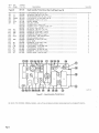
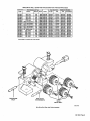
1
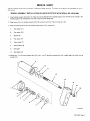
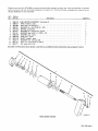
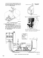
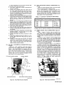
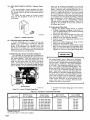
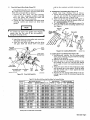
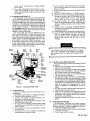
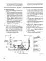
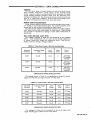
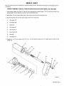
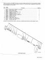
August 1973
FORM: OM-1234
MODEL
STOCK NO.
MILLERMATIC 3OAN
CONTROL/FEEDER
MODEL/STOCK NO.
SERIAL/STYLE NO.
OWNERS
.030 Wire V-Groove
058 484
.035 Wire V-Groove
058 485
.045 Wire V-Groove
058 486
1/16 Wire V-Groove
058 488
.045 Wire U-Groove
058 489
.052 Wire V-Groove
058 487
1/16 Wire U-Groove
058 490
5/64 Wire U-Groove
058 491
3/32 Wire U-Groove
058 492
7/64 Wire U-Groove
058 493
1/8 Wire U-Groove
058 494
1/16 Wire V-Knurled
058 495
5/64 Wire V-Knurled
058 496
3/32 Wire V-Knurled
058 497
7/64 Wire V-Knurled
058 498
1/8 Wire V-Knurled
058 499
DATE PURCHASED
MANUAL
miller
.
MILLER ELECTRIC MFG. CO.
APPLETON, WISCONSIN, USA 54911
ADDITIONAL COPY
PRICE 75 CENTS
NWSA CODE NO. 4579
U8
~
ERRATA SHEET
After this manual
was
printed, refinements
in
equipment design occurred. This sheet lists exceptions
to
data
appearing
later in
this manual.
SPINDLE ASSEMBLY INSTALLATION ON UNITS EFFECTIVE WITH SERIAL NO. HE741 584
1.
spindle support shaft (item 12, Figure 2) into the desired hole in spindle support (13).
spindle support (13) will depend on the size of the wire spool being used.
Insert
2. Slide washer (14) onto spindle support shaft (12) and
3. Slide the following items onto the
A.
Flatwasher(11)
B.
Flatwasher(10)
C.
Spindle (9)
D.
Flat washer (8)
E.
Fiber washer (7)
F.
Keyed washer (6)
G.
Spring (5)
H.
Flat Washer (4)
4. Rotate hex
.
nut
(3)
onto
secure
spindle support shaft (12)
support shaft (12). Hex
-
nut
with nut
in order
(15) and
cotter
The hole to be utilized in the
pin (16).
given:
(3) should be rotated only until
a
slight drag is felt while turning
spindle (12).
9
10
11
12
13
14
15
16
1
2
3
4
5
6
8
B-058 675
OM-1234 Page A
Effective with serial No. HE741 584
with
an
alternate Hub &
Spindle Assembly has been used.
If the Control/Feeder is
aluminum hub refer to the parts breakdown in the parts list. If the Control/Feeder is equipped with
an
the parts breakdown
Item
Factory
No.
Part No.
1
058675
2
058427
3
601884
4
605941
5
010233
6
057971
7
010191
8
058628
9
058428
10
057618
11
602213
12
605181
13
605277
on
a
equipped
plastic hub use
this errata sheet.
Description
Quantity
HUB & SPINDLE ASSEMBLY
(consisting of)
RING, retaining spool
NUT, steel hex jam 5/8-1 1
WASHER, flat steel 41/64 ID x 1OD
SPRING, compression
WASHER, flat steel keyed 1-1/2 dia
WASHER, fiber 5/8 ID x 1-1/2OD x 1/8
WASHER, steel brake
HUB, spool plastic
SHAFT, support spool
WASHER, lock steel split 3/8
NUT, steel self locking hex 3/8-16
1
1
-
1
-
1
-
1
1
-
2
2
-
1
-
1
-
1
-
1
-
PIN,
cotter
3/32
BE SURE TO PROVIDE STOCK,
x
3/4
MODEL,
1
AND SERIAL NUMBERS WHEN ORDERING REPLACEMENT PARTS.
1
TB-058 675
Hub & Spindle Assembly
OM-1234 Page B
SECTION 1
1-1.
-
INTRODUCTION
GENERAL
The purpose of this manual is
toprovidethe
the torch or gun tip, the wire feed speed control
provides dynamic breaking of the motor when the
switch on the gun or torch is released. Circuitry and
plumbing to provide control of the shielding gas flow
basic
information required to,
and maintain
control/feeder. This manual will restrict It
self
mainly to the wire control/feeder and its
optional equipment. For specific information on
its gun or torch, refer to the respective manual.
the
to the
torchorgunisalsoincorporatedin
assembly.
The control unit
requires 115 volt 60
from the welding machine
1.2.
DESCRIPTION
The control/feeder is of the constant wire feed
This 115 volt
operation.
speed type and is designed to be used in con~
junction with a CP (Constant Potential) type of weld
or
ac
external
hertz
ac
source
for
Is connected to
source
and is fed
assembly
the control
the control
backthrougha 115/
24 volt
step down transformer and the contactor con
receptacle to actuate a contactor. The con
tactor may be either the primary typeor secondary
type as long as It can be actuated by applying 115
trol
ing
power source.
This unit was designed to handle .030
to 3/32
alloy solidwiresand.045to 1/8 flux
cored wires. Either the short circuiting method of
transfer or the spray type arc may be utilized.
The control/feeder comes from the factory
equipped with a 30 tooth fiber gear on the motor and
mild and low
volt
to the contactor coil.
step down transformer incorporated in the
control assembly provides a low voltage (24 volts)
ac
The
the torch
across
of
tion
the
or
gun switch to control the opera
power source and the wire
welding
a
feed.
will
Hanging Bail (Optional), Part No. 056 716,has two
position adjustment for balancing suspended con
trol/feeder over work area. See Optional Equip
24 tooth steel gear on the drive. This combination
provide up to 550 ipm. A 24 tooth fiber and 15
tooth steel gear may be ordered as optional equip
ment to provide the flexibility of the seven different
wire feed speed ranges.
control/feeder is a heavy duty wire feeding
unit combining both the wire feeder and the control
in a compact assembly. It contains all the controls
and equipment needed to supply weldingwire, shield
ing gas and coolant (optional) tO the welding gun or
This unit consists basically of a control
torch.
assembly, a drive motor with reductional gear box
assembly, drive roll assembly, wire guides and a
spindle and hub assembly to accommodate a reel
assembly for handling wire coils or spool assembly
for handling wire spools.
The control assembly contains a solid state type
speed control for providing precise regulation of
ment section.
The control/feeder also has facilities for
This
motor
ipm.
modation of
Specifications (Figure 11).
1-3.
Refer to the
the
speeds over a wire feed range of 15 to 850
prevent override or run out of the wire at
ELECTRODE WIRE
CONTROL CIRCUIT
FEED SPEED
POWER AT TORCH
1/8
-
15 to 850
ipm.
RULES
FOR OPERA
TION OF ARC WELDING MACHINES.
DIA. CAPABILITY
.126
3.2MM
safety section under OPERATION and
complete safety section in the Power Source In
struction Manual SAFETY
ELECTRODE WIRE
)ecimal .031
Vletric .8MM
SAFETY
Before attempting to make primary or secondary
connections, change parts or make repairs,be sure
the power source and control/feeder equipment is
completely disconnected from the main power line.
To
Fraction .030
accom
remote control. The remote control
unit may be ordered as optional equipment.
For
particulars on control/feeder refer to the
a
WE GIlT
DIMENSIONS
24 volt
HEIGHT
WIDTH
241/2
14
LENGTH
5/8
NET
341/4
66
SHIPPING
71
~
~
Figure
1-1.
Specifications
SECTION 2- INSTALLATION
2-1.
LOCATION
of the
Figure 21 for dimensional information
the wire control/feeder.
Lead lengths must
on
be considered when installing the control/feeder.
If the welding machine can be located near the
work area, the control/feeder can usually be in
stalled on top of the welding machine.
Suitable
should be allowed for making necessary
space
the red
Refer to
The
is
put
control/feeder. See Figure 2-2 for the location of
stop.
oil
level should be checked before the unit
into
operation and periodically thereafter.
HOUSING, remove
To check oil level in the GEAR
the
OIL LEVEL PLUG in the GEAR HOUSING END
SHIELD
ASSEMBLY
necessary, until oil
and
runs
add
SAE
No. 90 oil, If
out the OIL LEVEL HOLE.
connections.
2-3.
2-2.
DRIVE
The
MOTOR
red
AND
GEAR
HOUSING
(Figure 2-2)
stop, which is inserted into the hole in the
plug, must be removed prior to operation
vented oil fill
GAS CONNECTIONS FROM SUPPLY
FEEDER (Figure 2-5)
Determine the distance the
located from the
welding
TO CONTROL!
control/feeder
Is to be
machine and then connect
OM-1234 Page 1
a
hose
from the gas
shielding
rear
regulatorflowrneter on the
supply to the GAS IN connection on the
control/feeder control panel. This con
REMOVE & DISCARD
gas
of the
nection has
a
RED STOP PRIOR
VENTED OIL PILL PLUG
TO OPERATION
right hand thread
PLUG
AA-O56 132-9
Figure
Figure 2-1.
2-4.
WATER
2-2.
Vented Oil
Plug
And Oil Level
Plug
Control/Feeder Dimensions
CONNECTIONS
FROM
SUPPLY
TO
CON
TROL/FEEDER (Figure 2-3 & 2-4)
The Water
able
as
torch is
Cooling Kit (Part No. 056 351) is avail
optional equipment. When a water cooled
used, connect a hose fromthewater supply
to the WATER
IN male connection
the
control/feeder
has
a
control
panel.
on
the
rear
of
This connection
left hand thread
Water coolant
AA-056 132-5A
Figure 2-3.
Water Coolant Kit Connections
cAeLE LEGEND
C
ma
115 VOLTS A C
CON TACTOS CONTROL
ELECTRODE
C
WORK
E9
OAT IN
C
GAS OUT
C
SWITCH CONTROL
11111
CONDUIT ASSEMRLY
i CABLE
Figure 2-4.
Page
2
Control/Feeder Interconnection Diagram
CONNECTION
AD-055 132-lA
If field installation of the WATER COOLING KIT
required, follow
is
1.
the
2-6.
steps below:
WELD CONTACTOR CONTROL CONNECTIONS
The Water
Cooling Kit mounts underneath the
Assembly.
Remove the coupling from the torch end of
the water outlet pipe and from the rear of Con
trol Assembly, insert the pipe end of the Water
Coolant Kit through the holes provided on the
Control Assembly Supports opposite the shield
ing gas solenoid and fittings.
Two holes are provided inthebottompanelwhich
Control
2.
3.
as
(Fig
2-4)
ure
Make up a 16/2 conductor cable the same length
the 115 volt ac three conductor cord.
The control/feeder is supplied with the nec
must be attached to one
which
plug
male
essary
Connect this cable
end of the two conductor cord.
CONTROL receptacle on the
welding machine and to the female receptacle on the
rear panel of the control/feeder.
CONTACTOR
to the
TABLE 2-1. Cable Size For Gas Metal-Arc (MIG) Welding
in the bottom of the
Fasten the WATER COOLING
KIT to the bottom panel with two 10-32 x 1/4
match with the two holes
solenoid valve.
AMPERES
screws.
six prong plug (to which the gas
solenoid leads are connected from the recep
4.
Remove
5.
panel of the control. Remove the
pin which holds the cover to the base of the plug.
Loosen the strain relief clamp screws and re
tacle in the
rear
tape from the leads.
the
move
Dress the twoleads
6.
to the six prong
lief
plug
from the water solenoid up
and through the strain re
plug
plug
terminal number 5. (Figure 23)
Replace the plug cap and pin removed in step
8.
24. 4.
9. Thread the coupling removed in step 2-4. 2.
water inlet
the
to
If
200
15 Feet
300
15 Feet
400
15 Feet
500
15 Feet
600
15 Feet
longer
cable is
pipe along with
rest of
the
Connect
hose
a
from
TO DRAIN
WATER
the
connection and connect the other end to
drain
or
inlet
if
a
water coolant
a
water
circulating system
is
connect the water drain end to the return
used,
on
water coolant
2-7.
Make
feeder.
Connect
91/2
and
(Figure
Make up a 16/3 conductor cable long enough to
from the welding machine to the control/
The
control/feeder
is
supplied
with
nec
essary female plug which must be attached to one
end of the three conductor cable.
Connect this
cable to the 115 volt ac receptacle on the welding
receptacle
control/feeder.
machine and to the
panel of the
115 volt
for machine
ac
contactor
115 volt
ac
on
the
of
of suitable current
inch diameter hole to
large enough
a
rating having
end of this cable
one
diameter hole
lug
end of this cable to fit the POSITIVE
terminal
on
the
secondary
the
CABLE
feeder,
electrode
terminal
on
the
cable
on
the other
(+) secondary
This connection
welding machine.
polarity welding.
nect the other
reach
feeder.
lug
a
2-4
for
cable
welding
(Figure
welding cable of suitable size
welding cable size) long enough
the welding machine to the electrode
connector assembly on the control/
length
a
Table 21
(See
is for reverse
system.
115 VOLT AC RECEPTACLE CONNECTIONS
2-4 & 2-5)
rear
1
2/0
3/0
4/0
22/0
the size of cable listed.
CONNECTIONS
SOURCE WELD
POWER
& 2-6)
Connect
2-5.
No.
No.
No.
No.
No.
required, double
to reach from
on
fittings.
the
10.
CABLE SIZE
clamp.~..
Connect and solder separately one lead to
terminal number 3 and the other lead to
7.
MAX. CABLE LENGTH
the
to
the POSITIVE
Con
welding machine.
end to the ELECTRODE WELDING
CONNECTOR ASSEMBLY on the control/
but do not tighten as the electrode cable
from the Gun
or
Torchwill also be connected to this
Make up a welding cable of proper size
terminal.
and of suitable length (see Table 21) to reach from
the
end
welding
of
this
machine to the
cable
a
workpiece.
suitable
Attach to
diameter hole
and connect to the NEGATIVE
(-) terminal
on
one
lug
the
welding machine. Attach to the other end of the
cable a C~
type clamp and make a good solid
connection to the workpiece.
Accessory receptacle
\/r
~~iLIZTFl
Motor
receptacle
~
J
ll5voltac
line
input
L(~UrL
/
Shielding
\
gas connection
Water coolant connection
(Optional)
Electrode welding cable
connector
assembly
AA-056 132-5A
AA-056 132-6
Figure
2-5.
Rear Panel Of Control
Assembly
Figure
2-6.
Power Source Connection
OM-1234
Page
3
2-8.
WIRE SPEED REMOTE CONTROL
(Optional) (Figure
motor not be
2-7)
The control/feeder1 comes equipped with facil
ities to accommodate remote control of wire speed.
The B emote Control unit may be obtained
as
To
install
the
optional
unit, insert the Remote Control
on
the
less than
at
on
a
wire feed
the
feeder.
equipment.
Plug into the receptacle
trol/feeder.
operated consistently
a 30 percent setting
control/
Operation with asettingof less than 30 per
cent when using large diameter electrode wire, may
result in a high current draw by the motor causing
the circuit breaker to activate. Also, operation on
the lower 30 percent of the control may not provide
an acceptable wire feed speed adjustment. Selecting
gear combinations, so the feeder will function as
high as possible on the control/feeder setting,
will give the best operating conditions. Table 66 A
thr9ugl-1 0 are provided to aid In the selection of
speed
face of the Con
the proper gear sizes.
B.
AA-056 890
Figure
2-9.
Remote Control Unit
2.7.
PREPARATION OF CONTROL/FEEDER
On new equipment, or as a result of wire size
changes, it is necessary to install the required
speed change gears, drive roll gears, and wire
guides
to
accommodate
the
particular wire
Changing Speed Change Gears
Change the Speed Change Gears as follows:
1. If speed change gear changing is necessary, re
move the speed reduction gear cover by removing
the two 1/4 inch screws.
2. Loosen the two bolts fastening the Drive Roll
Assembly to the base of the control/feeder.
3. Slide the drive roll assembly forward.
4. Remove the speed change gear from the Drive
Roll Assembly.
5. Remove the speed change gear from the drive
motor gear box assembly shaft.
to Table 22 for proper gears, install
gears on drive motor gear box assembly, drive
shaft and on the Drive Roll Assembly drive shaft,
Refering
6.
size
and thread the
welding wire. Having selected the
desired wire size and related parts, proceed to the
following installation and adjustment.
A.
Speed Change Gears (Figure 2-8) (TABLE
6-6
Tighten
selection of the proper gear combination is
important In obtaining the ultimate in performance of
a
With the proper gear com
finer wire feed speed adjustment can be
made and the drive motor will deliver maximum
The feeder may be usedatany setting on the
where
be obtained.
can
an
speed change gear.
fiber and a steel gear
in the drive train between the drive motor and the
wire drive rolls. Proper clearance between the fiber
control/feeder
The
power.
control/feeder
each
I.
control/feeder.
the
screws on
I IMPORTAN~1
Page 13)
The
bination
set
uses
a
and steel gear is important. The proper clearance
is .007 inch. This is approximatelythe same thick
The
ness of two sheets of standard writing paper.
easiest method to obtain the proper alignment is to
adequate feeding condition
It is recommended that the drive
the motor is fastened securely to the base
a piece of .007 thick paper (or
two thicknesses of standard writing paper) between
the fiber and steel gear, check the alignment of the
be
sure
plate.
Then insert
gears (the two gears must be running in
a
straight
line) and then tighten down the drive roll assembly.
If this proper clearance is not maintained in the
gears, they may wear severely, bind and cause
erratic wire feed, or even break.
I
Speed change
gears
AA-056 132-3
Location Of
Figure 2-8.
Speed Change Gears
7.
Reinstall
TABLE 2-2. Gear Sets For Various Wire Feed
GEAR SET
A
C~
D
C~
B
A
Page 4
use
2 fiber
or
cover over
the
Speeds
MOTOR GEAR
DRIVE GEAR
MIN. SPEED
MAX. SPEED
NO. OF TEETH
CONTROL SETTING
CONTROL SETTING
15 Steel
30 Fiber
15 Steel
24 Fiber
*Standard Gear Set
Do not
speed change gear
NO. OF TEETH
(056 094)
(056 094)
24 Steel (056 095)
24 Fiber (056 092)
30 Fiber (056 093)
24 Fiber (056 092)
30 Fiber (056 093)
B
the
gears.
steel gears
together.
30
24
24
15
15
(056 093)
(056 092)
Fiber (056 093)
Steel (056 095)
Steel (056 095)
Steel (05~ 094)
Steel (056 094)
20
225 ipm
25
280 ipm
ipm
ipm
35 ipm
45 ipm
50 1pm
79 1pm
90 1pm
370
1pm
1pm
550 1pm
745 ipm
900 1pm
450
C.
(Figure 2-9)
Drive Roll Gears & Wire Guides
with the four washers and bolts removed in
step
1.
After
determining
the wire size to be
the proper drive roll gears and wire
Table 23 and install them as follows:
1.
Flemove
bolts
the
and
drive
four
their
roll
used, select
guides from
gear
securing
respective washers
from the
drive roll
drive
roll gears
and remove the
gears from the drive roll assembly.
2. Loosen the inlet, intermediate, and outlet
securing screws and remove all three
0.
Installing Reel Type Welding Wire (Figure 2-10)
Reel Type Welding Wire as follows:
Install
1. Loosen the four wing nuts on the wire reel, and
pull out and turn the four fingers toward the
center of the wire reel. (Figure 210)
2.
Place coil of wire onto the wire reel
fingers
so
.the wire will pay off from the bottom of the coil
in a counterclockwise direction.
3. Turn two opposite wire reel fingers outward. Do
guide
wire
guides.
the
with the two
same
reel
remaining opposite
wire
fingers.
,Fingers
Retaining
Ring
I
I
To
prevent the three wire guides from slipping
ensure
facing
that
the
flat
the
securing
of
side
the
wire
is
guide
screw.
U
U
Lock
Washer
3. Install the three
wire
wire
new
guide securing
4. Slide the
roll gear
shaft
and secure the
Cotter
Pin
roll gears onto the drive
drive roll gears
secure
drive
new
guides
screws.
and
(I
Self
Locking
Nut
Figure
E.
2-10. Installing
Welding
Wire
AD-056 132-A
Installing Spool Type Welding Wire (Figure 2.10)
1. Simultaneously depress the two spring loaded
stops on the retaining ring and slide the retaining
ring off of the spindle.
2. Slide the reel off of the spindle.
3. Slide the spool of wire onto the spindle so that
the welding wire will pay off from the bottom
of the spool of wire in a counterclockwise dir
ection.
4. Rotate the spool until the hole in the spool aligns
with the guide pin on the spindle. Slide the spool
Intermediate Guide
Securing Screw
Shipped
Intermediate
Guide
onto the
~ith torch
it
seats
against
5. Depress the two spring loaded stops
C-056 276A
Figure 2-9.
spindle until
spindle.
the back
side of the
Drive Roll
Assembly
taining ring
and slide the
on
retaining ring
the
re
onto the
spindle.
Table 2-3. Wire Drive Roll Gears And Wire Guides For Various Wire Sizes
Control/
Wire Diameter and
Fraction
Feeder
Gear Drive Roll
Type
Decimal
Kit No.
Part No.
Guide Part Numbers
Type
Inlet
Intermediate
058484
.030.
hard
.030
.8MM
058500
058516
V-Groove
056192
056206
058 485
.035
hard
.035
.9MM
068 501
058 517
V-Groove
056 192
056 206
058 486
.045
hard
.045
1.2MM
058 502
058 518
V-Groove
056 193
056 207
058 487
.052
hard
.052
1.3MM
058 503
058 482
V-Groove
056 193
056 207
058 488
1/16
hard
.062
1.6MM
058 504
058 519
V-Groove
056 195
056 209
058 489
.045
hard & cored
.045
1.2MM
058 505
058 520
U-Groove
056 193
056 207
058 490
1/16
hard & cored
.062
1.6MM
058 506
058 521
U-Groove
056 195
056 209
058491
5/64
hard&cored
.078
2.0MM
058507
058522
U-Groove
056195
056209
058 492
3/32
hard & cored
.093
2.4MM
058 508
058 523
U-Groove
056 196
056 210
058 493
7/64
hard & cored
.109
2.8MM
058 509
058 524
U-Groove
056 196
056 210
058 494
1/8
.125
3.2MM
058 510
058 525
U-Groove
056 197
056 211
hard & cored
058495
1/16
cored
062
16MM
058511
058526
V-Knurled
056 195
056209
058 496
5/64
cored
.078
2.0MM
058 512
058 527
V-Knurled
056 195
056 209
058 497
3/32
cored
.093
2.4MM
058 513
058 528
V-Knurled
056 196
056 210
058 498
7/64
cored
.109
Z8MM
058 514
058 529
V.Knurled
056 196
056 210
058 499
1/8
.125
32MM
058 515
058 530
V.Knurled
056 197
056 211
Outlet
~iide
cored
is furnished with torch
assembly.
OM.1234 Page 5
F. Adjusting Hub Tension
9. Place the RETRACT-FEED Switch in the FEED
position. (Figure 31)
10. Push the INCH Switch in the upward direction.
To
end
adjust hub tension, slowly unwind wire and pull
toward the drive roll gears to check hub tension,
wire should unwind
freely, but hub tension should be
sufficient to keep it taut and prevent backlash when
drive motor is stopped. If adjustment is required,
loosen
or
tighten
nut
run the wire through the torch or run
energizing the welding machine welding
If wire slippage occurs between drive
circuit,
rolls, tighten Pressure Adjustment Wing Nuts
If wire is run out beyond
until slippage stops.
the end of the hub shaft.
on
G. Threading The Welding Wire (Figure 2-9 and 2-11)
Proceed as follows to thread welding wire:
1. Loosen the wing nuts on the drive roll assembly,
the torch
.Switch
the pressure adjustment studs downward
and lift the upper drive rolls upward.
turn
Straighten or cut off the free endof the wire and
pass it through the inlet wire guide in the drive
roll assembly.
3. Continue the wire through the intermediate and
outlet guides.
4. Tip the upper drive roll gears downward making
6.
gun tip, plaCe the RETRACT-FEED
the RETRACT position and push the
or
in
upward position. Release
approximately
end of the torch or gun tip.
INCH
switch in the
INCH
switch after end of wire is
one
2.
5.
will
This
without
Be
from the
inch
sure
to RETURN RETRACT-FEED switch to
the FEED
position.
sure the upper drive gears mesh with the lower
drive gears.
Bring the drive roll pressure adjustment studs
upward making sure the lower washer comes
above the upper drive roll assemblies.
Turn the pressure
adjustment wing nut in the
clockwise direction until the drive roll gears are
tight against the welding wire. Do not tighten too
tight. Further adjustments canbe made after the
welding machine and control/feeder are put into
operation.
7.
or gun to the control/feeder
in
Torch or Gun
instructions
Connect the torch
to
according
Manual,
8.
AA-056 132-8
Place the
control/feeder
power switch in the ON
Figure
position.
SECTION 3
3-1.
-
3-2.
Comply with all ventiation, fire and other safety
requirements for welding as established for in
Reference as applicable:
dustrial applications.
1. Safety Rules for Operation of Arc Welding Ma
See Arc Welding Machine Instruction
chines
Prior to
A.
Metal-Arc
Society:
Because
American
Safe
and
Cutting
-
See
2. If
all
for
InertGas
American
the
following procedures
and
as
cabling
follows:
connections
for
fittings.
interconnections
where the
Welding
complete and satis
are
the gun
or
torch in
exposed welding
wire
a
safe location
(electrode)
will
not touch
3.
radiation emitted
by the
high-density arc in Gas Metal-Arc Welding methods,
FLASH GOGGLES (medium-shade) are recommend
ed in addition to HELMETS for the operator and
nearby personnel. The welding wire (electrode)
and all metal parts in contact with it are electri
cally energized while welding, thus requiring peri
odic inspection for broken insulation, water leakage
(if used) and other electrical hazards.
CAUTION
ensure
hose
factory, place
A6.1, 1958.
infra-red
Inspect
secure
Standards Asso
Practices
Welding
Bulletin
of
Welding
Z49.1, 1958.
ciation: Bulletin
Recommended
and Gas
welding,
accomplished.
Gas And Water Supply (Figure 3-1)
Connect gas and water supply
1.
Manual.
3.
PRE-WELD REQUIREMENTS
are
-
Safety In Electric
See
Operations
Threading Welding Wire
OPERATION
SAFETY REQUIREMENTS
2.
2-11.
Place
ON
4.
5,
6.
anything.
the welding
machine power switch in the
position.
Open
the valve
the gas
on
Turn
the
water
Push
the
PURGE
cylinder.
supply ON (if used).
coolant
button
and
adjust gas
flow
regulator. Hold the button in for a few seconds,
long enough to remove the airfromthe shielding
gas supply line.
I
NOTE
I
installing new equipment, or after prolonged
shutdown, allow shielding gas tO flow continuously
for at least one minute prior to welding in order to
When
I
steps are taken to remove and repair
hazards, place all power controls OFF and
Whenever
such
disconnect all electrical
machine.
I
Page
cabling
from the
purge the gas line,
welding
7,
Inspect
water
should be
6
no
(if used)
gland fittings
drain hose
leakage
at
.
,
.
there
and used
be observed
should
water
8. Wire is firmly seated between drive roll gears
flowing steadily
as
8.
If
circulating coolant system is used,
water fittings to gun or torch and for
water
a
check
water flow at the Water Return
ant
on
system.
Wire Speed Control (Figure 3-1)
The adjustment of this control is best determined
by the individual operation; difference between ap
plications, materials and desired end-results will
rates that vary from
12.
one
control/feeder andpositiontheSTD-RE
Switch on the control/feeder and on the re
mote control unit to the REMOTE position.
If it
is desired to return the control of the wire speed
MOTE
control/feeder, place
on
the
either the
control/feeder
remote control to the STD.
or
act
as
a
a
few
starting
hot start feature.
All power cables are
safety insulated and
properly interconnectedbetween control/feeder
and gun, welding machine, and primary power
welding.
STD.RE
the
the
one on
position.
U
Wire reel
Remote
Wire
Slow-fast
assembly
control
inch
switch
start
The
switch
with
receptacte
the wire for
Ground cable Is properly connected between
workplece and welding machine negative second
ary output terminal.
14. Welding machine is adjusted for required output.
requirements have been satis
15. If all preweld
fied for control/feeder and gun, all required
the
power controls are now positioned to ON,
operator may proceed with the trial or actual
a
MOTE Switch
will
source.
larger weld puddle.
speed may also be adjusted by a re
Connect the remote con
mote control (optional).
trol plug into the remote control receptable on the
to the
which
13.
The wire
face of the
speed of
the
duce
the clockwise direction will increase the wire feed
ing rate and will supply more wire into the arc and
deposit
through
SLOW-FAST START switch is in proper position.
Having the switch in the SLOW position will re
.cycles
application
to another. Wire feed speed adjustment is made by
means of the WIRE SPEED control on the front panel
of the control assembly.
Turning the control In
require feeding
the wire
9. Wire feeding rate has been preset on WIRE SPEED
control.
10. RETRACT-FEED Switch is in FEED position.
the water cool
11.
B.
push
with sufficient pressure to
the gun or torch.
out to sewer.
the
welding wire and all metal parts in contact
it are energized while welding. Do not touch
welding wire or any metal part making contact
with it.
I
3-6.
Wire
speed
GAS METAL-ARC (GMAW) WELDING
When performing gas metal-arc
as
control
welding proceed
follows:
Place the ON-OFF power switch on thecontrol/
feeder In the ON position.
2. Place the ON-OFF power switch on the welding
1.
Torch
or
gun
shielding gas
connection
Gear
oil
machine in the ON
case
vent
the
plug
~
pressure
adjustments
Drive roll
24 volt
assembly
switch
Torch
or
casing
cable
connection
Hold the
if drive roll pressure is properly adjusted to pre
slippage. If wire slippage is noticed, tighten
PRESSURE ADJUSTMENT NUTS
at
wise
tighten
3-1.
Wire Control/Feeder Panel
to
welding,
ensure
the
following
are
6.
ac
complished:
1.
2.
3.
All
safety requirements
are
7.
con
30
cycles (1/2
pay off tension.
Correct size wire drive
and gun
fittings
or
torch.
are
on the equipment are ad
justed for normal operating conditions, the con
installed
welding machine
automatically.
and
will
perform
Release the torch switch after the weld Is
com
pleted.
are
control/feeder
approximately
After all the controls
their duties
properly secured.
4. Shielding gas is provided and the source is ad
justed for proper flowrate.
5. If used, water circulating coolant source output
is adjusted; used water flow is visible to drain or
coolant system.
6. Wire spool is in place and adjusted for proper
7.
Gas flow will start
trol/feeder
known and in effect.
Electrical power controls are OFF.
All hose and cabling is in good condition;
nections
time
second) before the wire starts.
Pre-Weld Check List
Prior
1/4turnclock-
Do not
until slippage stops.
PRESSURE ADJUSTMENT NUTS too
a
much.
5.
C.
torch handle.
vent
connection
Figure
or
Gas will start to flow and wire will start to feed
Weld cable
connection
gun
control
This will energize
control/feeder.
or torch approximately
position.
machine and
tip of the gun
1/2 inch from the workplece.
4. Energize the trigger on the gun
3.
Weld cable
relief
Drive roll
welding
3-7.
SHUTDOWN PROCEDURES
Environmental
safety require
equipment shutdown
Shutdown equipment as follows:
conditions
and
ments will determine extent of
between
operation.
welding power
1.
Shutdown
2.
Place the ON-OFF switch
in the OFF
on
3.
source.
on
the
control/feeder
position.
Turn off gas valve at source.
OM.1234
Page
7
system is
possibly fall
coolant
may
to the coolant system tank
sufficient antifreeze
4. If used, turn off water supply and blowout water
lines with compressed air. Ifawater circulating
and
operate the coolant system long enough
properly
temperature
below the freezing point, add
used where the
antifreeze
mix
the
15
inch
with
to
the water.
SECTION 4- MAINTENANCE
4-1.
INSPECTION AND UPKEEP
Usage and shop conditions will determine fre
quency and
as follows:
1.
2.
3.
Make
of maintenance.
type
welding
Inspect
parts: tighten, repai~
and replace as required.
any weld spatter of foreign
matter which may accumulate around the nozzle
Use a hardwood stick, never a metal
orifice.
Carefully
Repair
remove
or
6.
replace,
as
give particular
cracked
5.
insulation
required,
all hose
and
frayed
and
attention to
and
areas
(7).
wire
(10)
This is to
and tie
finger
prevent the wire from unraveling
or
removed from either
wire is
assembly (1) or hub assembly (8).
3. Grasp the wire close to spool to prevent from
unwinding. Cut the welding wire (10) between
where the wire is grasped andwhere it enters the
drive roll assembly (11).
4. -Tie the wire (10) to the edge of wire coil or
spool (1) and remove coil or spool from control/
feeder.
5.
equipment.
6.
Remove grease and grime from components;
moisture from electrical parts and cable.
Blow out the casing with compressed air when
7.
chips
8.
This will remove any metal
and dirt that may have accumulated.
pieces of
the wire reel
where it enters
changing wire.
9.
42.
four
when the coil
machine power switch is OFF.
torch for broken areas, cracks andloose
sure
cable;
Cut
around the wire coil between each reel
Inspect equipment
tool.
4.
2.
Loosen the pressure adjustment wing nuts (3)
by turning in counterclockwise direction.
Remove welding wire (10) from torch(5) (orgun)
and drive roll assembly (11).
Select the correct wire size drive roll gears (2)
and wire guides (4) from Table 2-3.
Remove the drive roll gears (2) from the drive
roll gear shaft (9).
Remove the wire guides (4) from drive roll
assembly (11) and replace with proper wire
guides (4) from Table 2-3.
Install proper drive roll gears (2).
(Figure 4-1)
Each time the wire size is changed, the gun or
torch and control/feeder must be ad~pted for use
with the new size wire. This consists of changing
11.
in the gun or torch and
guides in the control/
Remove gas
(or gun).
12.
Refer to Torch or Gun Manual for proper
ponents. Install or replace torch or gun
CHANGING WIRE SIZE
the wire contact
the
roll gears and
For proper gun or torch wire guide com
refer to appropriate gun or torch manual.
drive
feeder.
components
ponents,
To adapt the gun arid torch and control/feeder for
the new wire size, proceed as follows:
1.
Position all power switches to OFF.
~0.
nozzle
(6) from end of torch (5)
com
com
ponents as required.
13. Replace gas nozzle (6).
G. for Installation
14. Refer to paragraph 29.
Threading procedures of new wire size.
and
LEGEND
1. Wire Reel
Assembly
2. Drive Rolls
3. Pressure Adjustment Wing Nuts
4. Wire Guides
5. Torch
6. Gas Nozzle
7. Reel
Fingers
8. Hub
Assembly
9. Drive Roll Gear Shaft
10. Electrode Wire
11. Drive Roll Assembly
AC-056 132-bA
Figure 4-1.
Page 8
Changing Wire Size
1
132-1D2
ATRC5L&I~
33
Diagram CB-056
MCORECT RC-OPTINAL R18&R19 REVISON
39T0
Circuit No.
CKT.
DELTE
ADD
ST. ST S.T.
BY
9-7 1 8-1 70 2-5 70 DATE
REF
D2 Di
UNIJCTO
VIEW
END
LEAD
~Qi SCR
Diagram
Circuit
4-2.
Figure
0
SECTION 5
TROUBLE SHOOTING
-
TROUBLE SHOOTING GAS METAL-ARC WELDING PROCESSES AND EQUIPMENT
INTRODUCTION
When
as
soon
troubleshooting
gas
into
one
possible
as
metal-arc
of the
welding process
following categories:
Electrical
1.
2.
and
it is well to isolate and
equipment problems
Mechanical
them
Process
3.
This eliminates much needless lost time and effort. The data collected here dicusses
lems of gas metalarc welding processes. A little thought will probably enable solving the
the information provided.
The
classify
some
of the
common
prob
particular problem through
assumption of this data is that a proper welding condition has been achieved and has been used until trouble
In all cases of equipment malfunction the manufacturers recommendations should be strictly adhered to
developed.
and followed.
A.
f.
PROBLEM
Control/feeder
stops
electrode wire
feeding
while
welding.
3.
PROBABLE CAUSE
1.
2.
c.
d.
e.
f.
3.
Protective fuse blown.
Wire drive roll gears
4.
Casing
Broken
c.
Torch
d.
broken.
Contact
e.
misaligned.
Gun
body and/or
or
accessories
aspirating atmos
air.
b.
Contact tube extended too far.
c.
Nozzle to work distance too
d.
e.
Improper torch angle.
Welding speed too fast.
f.
Electrode not centered in nozzle.
-
5.
D.
liner
dirty, restricted.
damaged casing or liner.
trigger switch defective or wire
great.
Improper Electrode Wire Composition.
PROBLEM:
Welding
or
Electrode wire stubs into
workplece.
leads
PROBABLE CAUSE
tube
orifice
restricted; burnback of
1.
Power Source.
Excessive slope
numerical
electrode.
a.
Friction in torch.
b. Arc voltage too low.
Wire Control/Feeder.
PROBLEM:
Excess wire feed
a.
Electrode wire feeds but is not
ing
Gas solenoid defective.
Gas hose connections loose.
Torch and Casing Assembly.
phere
2.
B.
Freezing of CO2 regulator/flowmeter.
control/feeder.
Wire
a.
g. Drive roll gears worn; slipping.
h. Drive motor burned out.
Torch And Casing Assembly.
b.
shielding gas flow.
shielding gas.
b.
Drive roll pressure too great.
Spindle friction too great.
Excess loading of drive motor.
a.
Moisture in
a.
Primary line fuse blown.
Wire control/feeder.
Control relay defective.
a.
b.
Insufficient
g.
h.
energized.
values set.
speed.
No weld
E.
arc.
PROBLEM:
Excessive
spatter while welding.
PROBABLE CAUSE
1.
Primary
2.
Power Source.
Contactor plug not
a.
b.
c.
PROBABLE CAUSE:
Line Fuse Blown.
1.
tight
in socket.
Contactor control leads broken.
Remote-Standard switch defective
or
2.
in wrong
position.
Primary contactor coil defective.
e.
Primary contactor points defective.
f. Welding cables loose on terminals.
g. Ground connection loose.
Wire Control/Feeder.
a.
b.
C.
3.
4.
F.
System.
b. Insufficient gas flow.
Power Source.
a~
Excessive
b.
Insufficient slope setting value.
Torch
arc
contact
voltage.
tube
recessed in nozzle too far.
Improper electrode.
PROBLEM:
Weld bead appearance indicates
perage and/or larger bead.
Contactor
plug not properly seated.
Contact relay defective.
PROBLEM:
Porosity
Gas
Excessive gas flow rates.
a.
d.
3.
Shielding
need for
more am
PROBABLE CAUSE:
In the weld
deposit.
1.
Power Source.
Volt-ampere
a.
condition too low.
PROBABLE CAUSE:
1.
2.
Pa~ 10
Dirty base metal; heavy oxides, mill scale.
Gas cylinder and distribution system.
Gas cylinder valve off.
a.
b. Regulator diaphragm defective.
c.
Flowmeter cracked
d.
Gas
supply
hose connections loose.
e.
Gas
supply
hose leaks.
or
broken.
G.
PROBLEM:
Weld
bead appearance indicates
and/or smaller bead.
need for
perage
PROBABLE CAUSE
1.
Power Source.
a.
Volt-ampere
condition too
high.
less
am
SECTION 6
DATA CHARTS
-
GENERAL
The
two
basic
transfer
Spray
types of metal transfer are spray and short circuit.
comprises a steady stream of fine droplets moving
physical space from the electrode to the workpiece. The short
welding technique transfers metal from the electrode to the
workpiece on contact only. The electrode physically touches the work and,
since it is electrically energized, short circuits the welding circuit.
The short circuiting action occurs many times per second.
across
a
circuit
POWER SOURCE REQUIREMENTS
Power
arc
sources
welding
is
with the spray transfer technique of gas metalpotential type. The constant potential power
required
the constant
may or may not have some method of slope control.
The short circuit method of metal transfer requires a constant
source
potential
class power source with some method of slope control. Slope settings
may be fixed or adjustable by tapping a reactor either mechanically or
electrically.
MILD STEEL AND LOW ALLOY STEEL
in Table 6-1 are applicable to most weldable
Some modifications will be made for any specific application,
The
settings provided
steels.
of
course, because the ranges are necessarily
stitute a basis for setting a welding condition.
TABLE 6-1. Short Circuit Transfer
Mild And Low
-
They
broad.
will
con
Alloy Steels
Electrode
Amperage Range
Load
Slope
Power
Diameter
dcrp
Voltage
Turns
Source
0.030
70130
1521
250
6
CP
~
Amp
Welding
Machine
0.035
80190
1622
6
250 Amp
CP
Welding
Machine
0.045
100225
1722
250
6
CP
Amp
Welding
Machine
APPROXIMATE POWER SOURCE SETTINGS
The
ing gas
settings shown
in
for mild steel and
TABLE 6-2.
Table
61
are
Spray
Transfer
CO2
predicated on using
alloy steel.
shield
for low
ArgonCO2
-
Mild And Low
Alloy Steels
Electrode
Amperage Range
Load
Slope
Power
Diameter
dcrp
Voltage
Turns
Source
0.030
150265
2428
03
CP
Type
0.035
175290
2428
03
CP
Type
0.045
200315
2430
03
CP
Type
1/16
275500
2432
14
CPType
3/32
350600
2433
14
CP
Type
APPROXIMATE POWER SOURCE SETTINGS
The
oxygen
settings In Table 62
shielding gas for Mild
are
predicated on the
Alloy Steels.
use
of
Argon-S pct.
and Low
OM-1234 Page 11
TABLE 6-3. Short Circuit Transfer
Electrode
Diameter
Amperage Range
dcrp
Stainless Steel 300 Series
-
Load
Slope
Power
Voltage
Turns
Source
0.030
50145
1722
812
~P
Type w/slope
0.035
65175
1722
810
CP
Type w/slope
0.045
100210
1722
810
CP
Typew/slope
APPROXIMATE POWER SOURCE SETTINGS
The
settings
TABLE 6-4.
predicated on the use of a tn
pet. CO2 for Stainless
approximately 20 cfh.
Table 63
shown in
gas mixture of 90 pet. HE;
Steel 300 Series. Flow rates
are
7-1/2 pet. A; 21/2
were
Spray Transfer Stainless Steel
-
Load
Slope
Power
Voltage
Turns
Source
Electrode
Diameter
Amperage Range
300 Series
0.030
160210
2428
26
CP
Type
0.035
180255
2429
26
CP
Type
0.045
200300
2430
26
CF
Type
1/16
215325
2432
04
CP
Type
3/32
225375
2432
04
CP
Type
APPROXIMATE POWER SOURCE SETTINGS
The settings shown in
Oxygen shielding gases
centage
varies from 15
Table
for
6-4
Page 12
Arc
Amps
on
Series.
300
the
use
of
Argon-
Oxygen
per
pet.
TABLE 6-5.
Wire Size
predicated
Steel
are
Stainless
Flux Cored
Arc Volts
Settings
Gas
Type
Gas Flow
1/16
290325
2831
CO2
4048
CFH
5/64
350400
2932
CO2
4048
CFH
3/32
400450
2932
CO2
4048
CFH
7/64
425475
2932
CO2
4048
CFH
1/8
475
2932
CO2
4048
CFH
550
TABLE 6-6. Amperage
Output For Various Speed Change Gear Combinations
Figures Based On Use Of C02 Shielding Gas
Graph
Graph
A
B
CHANGE G
-/
600
7/64
3/32
7~_
~(
500
45C
400
-~
35C
~z~
2~
25C
a.
2
~:;
~
2
4
225
20C
4
175
~
150
.v,,u
125
1 OC
10
20
30
40
50
60
70
80
90
100
C
8- 0
10
20
30
40
50
60
70
80
90
70
100
130
170
230
270
315
415
515
565
2-30
45
65
85
lOS
140
170
220
275
340
SHAFT
DRIVE ROLL
MOTOR SHAFT
24
24
GEAR RATIO
30
Graph
CHANGE GEARS
550
1
0
360
DRIVE
GEAR RATIO
C
30
Graph D
ADEQUATE
RECOMMENDED
liT ii
i11~jI111
:~iii~
-
700
650
~ilii
7 -7.
600
5~64~
550
.-~
500
500
_~!~
450
~I16~
3/32
400
350
Z 71
300
275
~
4
275
~7
250
a.
~
~
~
250
4
200
225
225
200
17~.
175
ISC
150
l2~
125
ioe
2
75
-
50
50
-
4C
40
-
20
-
C
0-
R-( )
I
85
-
10
20
0
115
155
210
40
~0
63
270
360
390
,
0
550
SHAFT
80
90
10
R- 0
10
20
30
40
50
60
70
80
90
100
650
825
91
I
18
27
38
53
67
93
106
137
163
200
225
7
643
DRIVE ROLl
MOTOR SHAFT
15
15
GEAR RATIO
30
Graph E
CHANGE GEARS
-
Graph F
ADROUATE
RECOMMEND
0
CHANGE GEARS
ADEQUATE
43U
171
400
;;~
~-
~
250
2G0
350
7/64
4
175
175
150
150
125
125
-
-
~
-
50
40
40
20
1(E
0
8-0
10
20
30
40
50
60
70
80
1-55
95
130
170
225
260
350
435
540
275
~
250
4
200
2Z~~~_~
~~~
7
225
.-
~
~
175
-~-
--
-7-
125
100
75
.~
~
~
50
~
~
~
.030
40
~
-
-
-
-
-
20
~
0
MOTOR SHAFT
GEAR RATIO
24
R=Wire
.
75
50
~
~
~
~
~
150
~
100
75
7
~
-
--~:-4-
300
~
~ii.~iiizi
-
1117 7i1Tli2~..Z
350
7
332
250
/
32
450
275
225
J
400
I
275
4
ADROUAI
650
300
~
30
Graph G
EARS
6OO~R~2EE~
/
DRIVE
GEAR RATIO
Speed
Control
Settings
90
100
660 800
R-0
10
20
30
40
50
60
70
80
90
100
8-0
10
20
30
40
50
60
70
80
90
bOO
1-20
35
50
65
80
100
130
160
205
250
275
I
60
75
100
135
170
215
260
320
390
445
DRIVE ROLL
MOTOR SHAFT
is
is
GEAR RATIO
-
35
DRIVE ROLL
MOTOR SHAFT
24
24
DRIVE ROLL
GEAR RATIO
24
1= Inches Per Minute
OM.1234 Page 13
August 1973
FORM: OM-1234
MODEL
STOCK NO.
MILLERMATIC 3OAN
CONTROL/FEEDER
MODEL/STOCK NO.
SERIAL/STYLE NO.
.030 Wire V-Groove
058 484
.035 Wire V-Groove
058 485
.045 Wire V-Groove
058 486
1/16 Wire V-Groove
058 488
.045 Wire U-Groove
058 489
052 Wire V-Groove
058 487
1/16 Wire U-Groove
058 490
5/64 Wire U-Groove
058 491
3/32 Wire U-Groove
058 492
7/64 Wire U-Groove
058 493
1/8 Wire U-Groove
058 494
1/16 Wire V-Knurled
058 495
5/64 Wire V-Knurled
058 496
3/32 Wire V-Knurled
058 497
7/64 Wire V-Knurled
058 498
1/8 Wire V-Knurled
058499
DATE PURCHASED
PARTS LIST
MILLER ELECTRIC MFG. CO.
APPLETON, WISCONSIN, USA 54911
NWSA CODE NO. 4579
£ o
D056
Figure
OM-1234 Page 1
A
Main
Assembly
132-C
Item
Dia.
Factory
No.
Mkgs.
Part No.
Figure
Quantity
Description
Main Assembly
A
1
056 999
3
057 666
4
601 884
5
602 249
6
010 233
7
057 971
8
010 191
9
057 622
10
010 225
HUB & SHAFT ASSEMBLY
.
.
.
.
.
.
(consisting of)
1
1
RING, retaining
NUT, hex 5/811
WASHER, flat 5/8
1
S.A.E
1
SPRING
1
WASHER, keyed
WASHER, fiber
2
HUB ASSEMBLY
1
(consisting of)
1
11
057 618
12
602 213
13
605 181
14
605 277
16
602 213
17
601 871
PIN, roll 1/4 x 3/4
SHAFT, support
spool
WASHER, lock
split 3/8
NUT, self lockIng 3/816
PIN, cotter 3/32 x 3/4
WASHER, lock split 3/8
steel 3/816
NUT, hex
jam
18
057 331
STRAIN RELIEF ASSEMBLY
19
20
057 318
CLAMP, cable
2
057 327
CABLE
1
21
22
010 860
CLAMP
1
23
24
25
26
056 103
057 334
604 631
.
1
.
1
-
.
1
.
.
1
.
1
.
4
8
(consisting of)
2
CONTROL BOX ASSEMBLY (See Fig. B Page 4)
MOTOR & GEAR BOX ASSEMBLY (See Fig. C Page 8)
hex hd 1/4-20 x 1
SCREW, cap
1
1
8
-
32
056 330
33
601 839
34
038 825
35
601 840
36
602 247
37
056 327
WASHER, lock
split 1/4
GEAR, fiber 30 tooth
GEAR, fiber 24 tooth
GEAR, steel 15 tooth
SCREW, set 1/4-20 x 3/4
rear
HANDLE, lifting
WASHER, flat 3/8 S.A.E
SCREW, self tapping 1/420
WASHER, flat 1/4 S.A.E
SKID, base
brass 1/213
NUT, hex
STUD, brass
NUT, hex. brass 1/213 jam
WASHER, flat 1/2 S.A.E
drive roll
BAR, anchoring
38
056 225
BASE
39
057 320
HANDLE, lifting
40
604 538
2
41
601 959
42
058 546.
602 024
WASHER, flat 5/16 S.A.E
SCREW, cap hex hd 5/1618 x 11/2
DRIVE ASSEMBLY, wire (See Fig. D Page 10)
2
602 207
056 093
056 092
056 094
27
604 799
28
057 319
29
010 910
30
604 475
31
602 241
43
10
1
1
1
1
1
4
x
11/4
601 926
46
O56 331
GUARD, gear
47
012 236
LABEL
48
056 322
SUPPORT,
49
056 416
REEL ASSEMBLY
039 618
010 603
010 606
BE SURE TO PROVIDE
1
1
1
1
1
1
45
056 442
2
front
SCREW, drive No. 2
NAMEPLATE (order by stock, model and
hex hd 1/4-20 x 5/8
SCREW, cap
44
8
8
1
serial
2
1
1
numbers)
2
-
drive roll
1
1
reel
1
(See Fig. E Page 11)
twistlock 3 wire
CONNECTOR, body
CAP, twistlock 2 wire
barbed
FITTING, coupling
NUT,.brass 5/818 B. H. thread
1
1
-
1
1
-
STOCK,
1
MODEL AND SERIAL NUMBERS WHEN ORDERING REPLACEMENT PARTS.
OM-1234 Page 2
D-056 882
Figure
Page 3
B
Control Box Assembly
Item
Dia.
Factory
No.
Mkgs.
Part No.
Figure
B
057 334
69
BC6
70
Ti
71
S6
039 825
*036 135
*011 770
72
S4
011 990
73
SRi
*037 167
74
604 415
75
057 314
Quantity
Description
Control Box
Assembly (See Fig.
CONNECTOR, receptacle
-
A
Page 2 Item 22)
femal 6 pIn
SWITCH, toggle
SWITCH, toggle
1
-
-
minature SPDT
1
DPDT inch
1
1
BRIDGE ASSEMBLY
76
S5
011 232
77
S3
011 233
78
S2
011 059
WASHER, Insulating
BOARD ASSEMBLY, printed circuit (See Fig.
SWITCH, momentary push SPDT
SWITCH, toggle SPDT start
retract
SWITCH, toggle DPDT feeder
79
056 328
WRAPPER
80
010 301
81
012 617
BUSHING, steel
HOLDER, fuse
THYREACTOR, 150 volt
RESISTOR, 10 ohm 12 watt
FUSE, 10 ampere
82
TB 1
83
Ri
84
Fl
,2
*037 551
*030 942
*012 655
85
1
TRANSFORMER
1
Bi
Page 5)
1
1
1
1
-
1
1
2
1
1
2
2
DECAL
86
010 199
87
010 193
88
056 170
SPACER, 1/4 x 3/8
SPACER, 1/4 x 3/8
SHIELD, resistor
89
030 949
HEAT SINK
1
91
056 169
BRACKET, mtg heat sink
in
BUSHING, snap
BLOCK, terminal 2 post
RESISTOR, 5 ohm
3 wire twistlock
RECEPTACLE, motor base
PLUG, 6 prong
ADAPTER, right hand
HANGER, No. 2 Minerallic
SOLENOID, valve (consisting of)
COIL, 115 volt
NIPPLE, 1/4 x 9-3/4
RECEPTACLE, 6 wire
terminal
INSULATOR, nylon
RECEPTACLE, 4 wire
WASHER, fiber 1/4 ID x 1/2 OD x 1/16
CAPACITOR, 750 mfd 200 volt
rear
BRACKET, mtg
RECEPTACLE, twistlock 2 wire
1.5 ampere
BREAKER, circuit
DPST
SWITCH, toggle
front
BRACKET, mtg
GROMMET, rubber 9/16 ID 3/4 hole
COUPLING, 1/4 pipe
POTENTIOMETER, 15K ohm 2 watt
CASE, base with chassis
NAMEPLATE (order by model and style number)
WASHER, anti rattle 3/8
flush 2 wire
RECEPTACLE, twistlock
KNOB, potentiometer
BRACKET, mtg
printed circuit board
SOCKET, 10 pin
STRIP, terminal
BRACKET, mtg
printed circuit board
RELAY, 24 volt ac
1
92
057 084
93
iT
94
B2
95
RC7
038 855
*030 941
056 665
96
056 265
97
010 604
98
99
010 926
GS1
035 601
*033 050
100
101
RC4
102
103
104
105
010 190
056 266
026 837
RC1
Cl
106
054 116
602 193
*031 692
056 165
107
RC3
039 855
108
CB1
*011 991
109
Si
*011 020
110
056 166
ill
010 378
112
113
602 934
*030 943
114
056 720
115
010 929
116
117
RC2
039 759
118
019 609
119
056 214
120
RC5
121
038 784
122
123
039 756
056 171
CR1
*034 841
x
x
15/16
1/4
2
6
1
1
-
1
1
1
-
1
2
1
1
1
1
1
2
-
1
1
1
1
-
1
1
-
1
-
1
-
1
1
1
1
1
1
1
-
1
1
-
1
1
1
-
1
*Recommended Spare Parts
BE SURE TO PROVIDE
STOCK,
MODEL AND STYLE NUMBERS WHEN ORDERING REPLACEMENT
PARTS.
OM-1234
Page
4
Item
Dju.
1actory
No.
FvIkgs.
Part No.
Figure Bi
057 314
Board Assembty, Printed Circuit (See
030 090
CAPACITOR, 80 mId 25 volt
RESISTOR, 33K ohm 1/2 watt
POTENTIOMETER, 5K ohm 2 watt
CAPACITOR, .01 rnfd 500 volts dc
RESISTOR, 10 ohm 1/2 watt
DIODE, IN4820
5CR, No. C20B
brass 1/4
WASHER, flat
external tooth 1/4
WASHER, lock
NUT, hex
jam 1/428
RESISTOR, 18K ohm 1/2 watt
RESISTOR, 2.2K ohm 1/2 watt
RESISTOR, 6.8K ohm 1/2 watt
RESISTOR, 2K ohm 1/2 watt
CAPACITOR, .047 rnfd 200 volt
BOARD, printed circuit
RESISTOR, 47 ohm 1/2 watt
037 261
HEAT SINK
RESISTOR, 4.7K ohm 2 watt
TRANSFORMER, pulse
CAPACITOR, .2 mId 200 volt
TRANSISTOR, unijuctwn
CAPACITOR, .33 mId 75 volt
RESISTOR, 1.2K ohm 1/2 watt
DIODE, zener 1 watt 24 volt
131
C I
031 633
132
IC)
030 936
133
118
030 944
134
C4,8,9
031 643
135
113
030 937
136
D14
037 061
137
Qi
037 824
010 915
602 208
601 867
138
114
030 854
139
1110
030 853
141
1112
030 934
142
117
030 940
143
C2,3
031 694
144
145
057 332
1120
146
Qu~intity
Description
147
116
030 945
148
T2
036 143
149
C12
031 721
150
Q2
037 289
151
C7
031 693
152
1111
030 938
153
D5
037 250
Fig.
B
Page
4 Item
75)
-
1
1
1
3
1
4
1
1
1
1
1
1
1
1
2
1
1
1
1
1
1
1
1
1
1
A.057 314
Figure
BE SUJIE TO PROVIDE
Page 5
STOCK,
B1
Board Assembly. Printed Circuit
MODEL AND STYLE NUMBERS WHEN ORDERING REPLACEMENT PARTS.
WIRE DRIVE ROLL GEARS AND WIRE GUIDES FOR VARIOUS WIRE SIZES
Control/
Wire Diameter and Type
Feeder
Decimal
Gear Drive Roll
Guide Part Numbers
Metric
Kit No.
Part No.
Type
Inlet
Intermediate
058 484
.030
hard
.030
8MM
058 500
058 516
V-Groove
056 192
056 206
058485
.035
hard
.035
.9MM
068501
058517
V-Groove
056192
056206
058 486
.045
hard
.045
1.2MM
058 502
058 518
V-Groove
056 193
056 207
058 487
.052
hard
.052
1.3MM
058 503
058 482
V-Groove
056 193
056 207
058 488
1/16
hard
.062
1.6MM
058 504
058 519
V-Groove
056 195
056 209
056 207
058 489
.045
hard & cored
.045
1.2MM
058 505
058 520
U-Groove
056 193
058 490
1/16
hard & cored
.062
1.6MM
058 506
058 521
U-Groove
056 195
056 209
491
5/64
hard & cored
.078
2.0MM
058 507
058 522
U-Groove
056 195
056 209
492
3/32
hard & cored
.093
2.4MM
058 508
058 523
U-Groove
056 196
056 210
493
7/64
hard&cored
.109
2.8MM
058509
058524
U-Groove
056196
056210
494
1/8
.125
3.2MM
058510
058525
U-Groove
056197
056211
hard&cored
495
1/16
cored
062
1.6MM
058 511
058 526
V-Knurled
056 195
056 209
496
5/64
cored
.078
2.0MM
058 512
058 527
V.Knurled
056 195
056 209
497
3/32
cored
.093
2.4MM
058 513
058 528
V-Knurled
056 196
056 210
498
7/64
cored
~109
2.8MM
058 514
058 529
V-Knurled
056 196
056 210
499
1/8
.125
3.2MM
058 515
058 530
V-Knurled
056 197
056 211
Outlet
WIRE GUIDE
INLET
Fraction
~jide
cored
is furnished with torch
assembly.
WIRE GUIDE
INTERMEDIATE
GEAR,
DRIVE ROLL
C-056 276A
Wire Drive Roll Gear And Guide Assembly
OM-1234 Page 6
-M
e
056 103
Figure
Page
7
C
Motor, Gear
Item
Dia.
Factory
No.
Mkgs.
Part No.
Figure
C
056 103
Quantity
Description
Motor, Gear (See Fig. A Page 2 Item 23)
PLUG, 4 prong
CORD, portable No. 18/4 conductor (order by foot)
1
1
056 373
PLATE,
bearing (closed)
WASHER, felt retainer
SCREW, ball bearing plate
WASHER, spacer
WASHER, spring
BEARING, ball
SCREW, shield
PIN, nameplate
177
056 264
178
604 571
179
054 393
180
054 394
181
054 395
182
054 396
183
054 434
184
054 397
185
054 403
186
2 ft.
ball
1
4
As
Regd
2
2
8
2
187
054 404
NAMEPLATE
1
188
054 406
RING & FIELD ASSEMBLY
1
189
054 407
BASE
1
190
054 408
SCREW, base
WASHER, spacing
GASKET, grease
SEAL, oil
4
191
054 413
192
054 414
193
054 415
194
054 416
195
054 433
196
054 424
As
Regd
1
1
1
197
054 423
198
199
054 432
200
054 430
201
056 374
202
056 375
WASHER, steel
PLUG, oil fill and air vent
GASKET, gear housing end shield
SCREW, gear housing end shield
SCREW, oil level
GASKET, oil screw
END SHIELD ASSEMBLY, gear housing
PLUG, gear housing
GASKET, gear housing plug
203
204
056 376
054 425
WASHER, spacing
205
056 377
GEAR & DRIVE SHAFT
206
054 420
END SHIELD
207
054 422
208
054 426
KEY
1
209
054 418
1
210
054 417
NUT, lock worm
GEAR, worm
211
054 411
ARMATURE
1
212
*056 378
054 399
BRUSH & SPRING ASSEMBLY
FRONT SHIELD ASSEMBLY (enclosed)
2
213
214
054 401
054 431
215
054 398
216
054 400
217
054 402
1
2
8
1
1
1
1
1
1
GEAR & REAR SHIELD HOUSING ASSEMBLY
As
Begd
1
1
ASSEMBLY, gear housing
1
SEAL
1
1
2
brushholder
SCREW, set
SCREW, brushholder cap
HOLDER, brush
BUSHING, terminal
-
2
2
1
*Recommended Spare Parts
BE SURE TO PROVIDE
STOCK, MODEL AND SERIAL NUMBERS WHEN ORDERING REPLACEMENT PARTS.
OM-1234 Pag3 8
TO-058 546
Figure
Page 9
D
Drive
Assembly. Wire
Item
Dia.
Factory
No.
Mkgs.
Part No.
Figure
0
058 546
Drive
GEAR, spur steel 24 tooth
SCREW, set 1/4.20 x 1/2
BEARING, thrust 5/S ID x 1/4 OD x 1/S
SCREW, cap steel hex head 1/4-20 x 3/4
WASHER, lock steel split 1/4
WASHER, flat steel SAE 1/4
PIN,cotter-hair
COVER, rear
COVER, front
HOUSING, drive (consisting of)
HOUSING, drive with bushing (consisting of)
BUSHING, flanged nylon 5/16 ID x 7/16 OD x 3/4
.PIN,spring3/16x1
FASTENER, pinned
BEARING, needle
SHAFT, drive roll
SCREW, cap steel hex head 1/4-20 x 1/2
SCREW, machine steel fillister head 1/4-20 x 1/2
PIN, machine steel 3/8 x 2-1/4
KEY, Woodruff 3/16 x 3/4
GEAR, spur fiber 15 tooth
SHAFT, drive gear
WASHER, flat steel SAE 5/16
SCREW, cap steel hex head 5/16-18 x 1-1/2
SPRING, compression bottom
NUT, steel wing 3/8-16
WASHER, flat steel SAE 3/8
SPRING, compression top
WASHER, flat steel standard 3/8
226
058 478
227
602 179
228
010 658
229
601 927
230
602 207
231
602 241
232
010313
233
056 152
234
056 151
235
058 483
236
058 168
237
058 112
238
010224
239
056 306
240
605 996
241
058 481
242
601 925
243
604 624
244
010 312
245
605 997
246
247
056 091
248
604 538
249
601 959
250
010 232
251
604 590
252
010 910
253
010 231
254
602 243
05S 480
BE SURE TO PROVIDE
Description
Assembly,
Wire (See
Fig.
A
Page
Quantity
2 Item 42)
-
-
-
-
1
2
1
4
4
8
1
1
1
1
1
.
-
.
.
2
2
2
.
2
.
-
-
-
-
-
-
-
-
-
-
-
STOCK, MODEL, AND SERIAL NUMBERS
4
4
3
1
2
1
1
2
2
2
2
2
2
2
WHEN ORDERING REPLACEMENT PARTS.
OM-1234 Page 10
Item
Dia.
Factory
No.
M}cgs.
Part No.
-
Figure
Quantity
Description
-
E
056 416
Reel
WASHER, flat 3/8 S.A.E
hex head 3/8-16
SCREW, cap
NUT, wing 1/2-13
Assembly (See Fig.
A
Page
2 Item 49)
261
010 910
262
601 964
263
604 051
264
056 312
FINGER
4
265
056 313
266
010 224
4
267
601 880
STUD, 1/2 x 7
PIN, roll 3/16 x 1
steel
NUT, hex
268
056 314
REEL
1
-
2
x
3/4
1
4
4
4
A-056 716
Figure
BE SURE TO PROVIDE
Page
11
STOCK,
E
Reel
Assembly
MODEL AND SERIAL NUMBERS WHEN ORDERING REPLACEMENT PARTS.
ERRATA SHEET
After this manual
was
printed, refinements
in
equipment design occurred. This sheet lists exceptions
to
data
appearing
later in
this manual.
SPINDLE ASSEMBLY INSTALLATION ON UNITS EFFECTIVE WITH SERIAL NO. HE741 584
spindle support shaft (item 12, Figure 2) into the desired hole in spindle support (13).
spindle support (13) will depend on the size of the wire spool being used.
1. Insert
spindle support shaft (12) and
2. Slide washer (14) onto
3. Slide the
following
items onto the
A.
Flatwasher(11)
B.
Flat washer (10)
C.
Spindle (9)
D.
Flat washer (8)
E.
Fiber washer (7)
F.
Keyed washer (6)
G.
Spring (5)
H.
Flat Washer (4)
4. Rotate hex
-
nut
(3)
onto
secure
spindle support shaft (12)
support shaft (12). Hex
-
nut
The hole to be utilized in the
with nut (15) and cotter pin (16).
in order
(3) should
given:
be rotated
only until
a
slight drag
is felt while
turning
spindle (12).
9
10
11
12
13
14
15
1
16
2
3
4
5
6
7
8
B-058 675
OM-1234
Page
A
Effective with serial No. HE741584
with
an
alternate Hub &
Spindle Assembly has
been used. If the Control/Feeder is
aluminum hub refer to the parts breakdown in the parts list. If the Control/Feeder is equipped with
the parts breakdown on this errata sheet.
an
Item
Factory
No.
Part No.
1
058675
2
058427
3
601884
4
605941
5
010233
6
057971
7
010191
8
058628
9
058428
10
057618
11
602213
12
605181
13
605277
a
equipped
plastic hub
Quantity
Description
(consisting of)
RING, retaining, spool
NUT, steel hex jam 5/811
WASHER, flat steel 41/64 ID x 1OD
SPRING, compression
WASHER, flat steel keyed 1-1/2 dia
WASHER, fiber 5/8 ID x 1-1/2OD x 1/8
WASHER, steel brake
HUB, spool plastic
SHAFT, support spool
WASHER, lock steel split 3/8
NUT, steel self locking hex 3/8-16
PIN, cotter 3/32 x 3/4
HUB & SPINDLE ASSEMBLY
BE SURE TO PROVIDE
use
1
1
1
-
1
-
1
1
-
2
2
-
1
-
1
-
1
-
1
-
1
STOCK, MODEL, AND SERIAL NUMBERS WHEN ORDERING REPLACEMENT PARTS.
1
TB-058 675
Hub & Spindle Assembly
OM-1234
Page
B