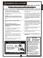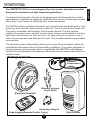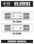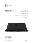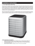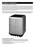
1
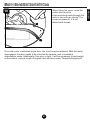
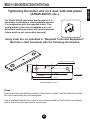
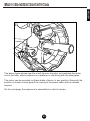
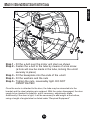
SENTRY
DCC02 Roll-up Garage
Door Automation
Installation and User Manual
ENG
Manufactured By Martin Electronics cc
PO BOX 49284, ROSETTENVILE 2130
Republic of South Africa
AFR
Vervaardig Deur Martin Electronics cc
Posbus 49284, ROSETTENVILE 2130
Republiek van Suid Afrika
ESP
Fabricado por Martin Electronics cc
PO BOX 49284, ROSETTENVILE 2130
la República Surafricana
DEU
Hergestellt durch Martin Electronics cc
PO-Kasten 49284, ROSETTENVILE 2130
Republik Südafrika
POWERED BY
Technical Support
For technical
queries relating
to use/installation
of this product!
+27 11 433 4084
Table of Contents
Warnings and Cautions for Use ................................................................. 5
Introduction ..................................................................................................
Package Contents ............................................................................
Door Types and Considerations .......................................................
Door Checklist ..................................................................................
6
6
7
8
Required Equipment ...................................................................................
9
Component Details .....................................................................................
Head Unit .........................................................................................
Wall Console ....................................................................................
Fitting Wall Console Cables .............................................................
10
10
11
12
Fitment of Motor to Door ............................................................................
Motor orientation and motor wire sequence ....................................
Fitment to standard platform doors ..................................................
Fitment to other door types (KRAZI-DOOR, etc...) ..........................
14
15
16
22
Fitment of Wall Console .............................................................................. 25
System Commissioning ..............................................................................
Connection Diagram For External Receiver .....................................
Connection Diagram For IR Beams .................................................
Connection Diagram for Remote Status LED ..................................
Powering Up The System ................................................................
Setting Up Door Limits .....................................................................
Adding weight to very light doors .....................................................
27
28
29
30
31
33
36
Programming Remote Controls ................................................................. 37
Selecting Remote Control Storage Slots .......................................... 38
Erasing all the remote controls ......................................................... 40
Advanced Features .....................................................................................
Activating and Deactivating auto-close ............................................
Adjusting the auto-close timer .........................................................
41
42
43
Troubleshooting Guide ..............................................................................
Limit Programming Troubleshooting .................................................
Operational and General Troubleshooting ........................................
Error codes and STATUS LED flashes .............................................
44
44
45
47
Product Specification .................................................................................. 48
3
ENGLISH
Company Profile ........................................................................................... 4
Company Profile
The company manufactures
remote controls, receivers,
infrared beams and garage
door automation products
under the Sentry brand
name.
The company also manufactures products for OEM (Original
Equipment Manufacturers) and custom markets and is deeply
respected in this regard as it designs and manufactures not only
its own products but specialised and custom products for
specific customers and provides support for these products.
MARTIN ELECTRONICS strives to give service and backup
second to none. Technical staff, as well as our engineers are
available to give answers to technical or installation problems.
The equipment is installed countrywide and is available through
a network of distributors in South Africa.
Further information is available on our website
www.martin-electronics.co.za
© Martin Electronics cc 2009
Martin Electronics cc. reserves the right to make changes to the products described in this manual without notice and without obligation of
Martin Electronics cc to notify any persons of any such revisions or changes. Additionally, Martin Electronics cc. makes no representations
or warranties with respect to this manual.
No part of this document may be copied, stored in a retrieval system or transmitted in any form or by any means electronic, mechanical,
optical or photographic, without the express prior written consent of Martin Electronics cc.
ENGLISH
Martin Electronics is a
respected and well-known
manufacturer of RF
remote controls and security
products and has
established itself as the
leader in RF remote control
for the past 20 years.
WARNINGS AND CAUTIONS
1.
Read all instructions and warnings
carefully before installing the product
2.
The product must only be installed by suitably
qualified persons.
3.
10. Never short circuit any wiring to and from
this equipment
11. The installer has a responsibility to explain to
the owner/user how the system operates
and how to deal with potential emergencies
NEVER allow children to play with the door or
that may arise during the scope and course
its remote controls and keep children and pets
of the product's application. The installer
away from the door, especially when it is being
must also pass on these instructions to the
used.
owner/user
4.
Secure all remote controls and opening
devices to prevent unauthorized access to the
door.
5.
Before attempting any work or
maintenance on the product, disconnect
the power and remove the batteries (if
applicable)
6.
All modifications not expressly approved by
the manufacturer are forbidden.
7.
Do not install the product in an explosive
14. Always ensure the manual override cord is
atmosphere or in any location subject to heavy
easily accessible at all times.
moisture ingress.
15. Never short circuit the wiring between the
Safety devices i.e. IR beam, must be fitted to
wall console and the motorised head unit, of
prevent death or injury by crushing due to
this product.
persons or pets being in the path of the door
curtain.
8.
9.
12. The product is designed and manufactured
only for the applications intended in this
manual. Any other use renders the warranty
null and void and neither the manufacturer or
its distributors, affiliates, servants, etc. shall
be held liable for any loss or damages
whatsoever.
13. This product employs double insulation, and
therefore does not require an earth
conductor.
Always keep objects, pets, and people away
from the path of a moving door.
Technical Support
For technical
queries relating
to use/installation
of this product!
+27 11 433 4084
5
NOTICE
REGARDING
BATTERIES
This product contains leadacid batteries, which may not
be disposed of by way of
regular household refuse.
Please consult with your
local authorities as to the
safe procedure of disposal
when the batteries are
replaced or product
disposed of.
DO NOT DISASSEMBLE
BATTERIES! CORROSIVE
SULPHURIC ACID!
ENGLISH
PLEASE READ THE FOLLOWING WARNINGS AND CAUTIONS
BEFORE INSTALLING OR USING THE PRODUCT.
RISK OF ELECTRIC SHOCK AND/OR FIRE
DO NOT TOUCH ANY COMPONENTS WHEN POWER IS APPLIED
Introduction
The product is designed to fit most roll-up garage doors that have plastic or metal
spool wheels. It operates by applying a rotational force to one of these spool wheels
which then in turn opens, or closes the door curtain as desired.
The DCC02 system consists of two parts, one of which is the motorised portion, that
drives the door, and fits inside the door curtain roll. This is known as the “head unit”.
This part is controlled, electronically, from the wall console. The wall console
contains the power source, and the remote control receiver and includes a courtesy
light and a control button on the front cover. To keep wiring to a minimum, only a
total of three wires are used between the units. This is made possible using a digital
one-wire bus.
The system provides limited battery back-up for mains failure situations. Alerts are
provided for both mains failure and low battery conditions. The system integrates a
learning remote control receiver which is compatible with SENTRY code hopping
remote control transmitters. A maximum of 8 remote controls may be learnt into the
system in total.
Package Contents
Power &
Interconnect
cables
Masonry anchors
(4 pcs 6x60)
Motorised Head Unit
U-bolt mounting kit
Code Hopping Remote Control (2 pcs)
6
Wall Console
ENGLISH
The SENTRY DCC02 is a second-generation roll-up door automation product
designed for domestic and light industrial applications.
Door Types and Considerations
Door Brands
This product is designed to operate, primarily with common types of roll-up door makes
and models found in the South African market. These include the WISPECO™ brand
and the KRAZI-DOOR brand. Other types are suitable, provided they meet the criteria
listed below.
Door Type
In general, the DCC02 is designed to operate the standard low-cost roll-up doors
commonly used in domestic applications- doors which are fabricated from thin
laminated steel or aluminium. It is not recommended for use with the 1970’s era heavy
steel roll-up type doors, which are much heavier than the common roll-up door types.
Door Sizing
The DCC02 is designed to drive a single door by itself. For particularly wide doors, the
product must be installed in the centre of the door, by fitting an additional adapter
wheel. It is not possible to fit two motor head units to a single door. The height of the
door is not a factor, therefore, standard height doors as well as “caravan doors” are
suitable candidates for this product.
Door Condition
The condition, and quality of the installation of the door plays a MAJOR role in whether
the installation of this product (or any other garage door automation product) will be
successful or not. Common problems that cause this product to fail, either immediately,
or after some time include:
Doors that are not true- These are doors that are installed skew, leading to the
formation of gaps at the bottom when the door is fully closed. The DCC02 does
close the door completely to the floor but it was not designed to drive the door
curtain into the floor to seal against flooding etc...
Doors that are not balanced- These are doors that, although they appear to be
light to move by hand, either suffer from tight spots during travel, or get stiff in
cold weather. The DCC02 can compensate to a large degree, for cold stiffness
but beyond this, will consistently go into over-current to protect the motor.
Doors that are too light- A frequent problem is a door that is too light, causing
the door to unravel at the top, when closing. In these cases, it is necessary to add
weight to the bottom of the door, in the form of a steel bar or angle iron. Doors
that are too light also cause the system to exhibit various symptoms. These
symptoms include moving short distances, stopping shortly after opening, etc..
7
ENGLISH
IMPORTANT - PLEASE READ THIS SECTION CAREFULLY TO
ENSURE THAT THE DOOR YOU INTEND TO AUTOMATE, MEETS
THE REQUIREMENTS FOR SUCCESSFUL AND TROUBLE-FREE
OPERATION!
Door Types and Considerations
ENGLISH
Doors with bent take-up spools- These are doors with bent spools, that
pull the head unit’s driving wheel proportionately skew. The product suffers
damage and exhibits all kinds of fault conditions, most commonly that of
moving short distances.
Door Condition Checklist
ý
Uneven Floor / Door Mounted Skew
ý
Unbalanced door (tends to open by itself due to
over-tensioned springs)
Door
Curtain
ü
Door lands flat on floor and doesn’t recoil
ü
Door equally easy to lift, or to pull down
ý
ü
Internal wheel
(plastic or metal)
Tube
Bent, warped, or skew spool wheels
This causes damage to the product and is
very common on badly installed doors and/or
very cheap doors!!
8
The start of the door curtain must be affixed at
the end, to the door spools using a tek screw. This
helps prevent problems and also secures the door
better against intrusion
Required Equipment for Installation
Small Side Cutter
Multimeter
Tek Screws
Length of
Angled Steel
Masonry Drill Bit
(6 ~ 6.5mm)
Length of
Rectangular steel bar
(To fabricate a baseplate for KRAZI DOORS)
Drill with
impact setting
HSS Drill Bits
(6 ~ 10mm)
Impact Drill
Spanner set (17 ~ 21)
9
ENGLISH
Philips screwdriver & Flat screwdriver
Component Detail - Head Unit
2
5
6
3
4
7
9
8
Shown with cover removed
6. Manual Override lanyard guide
7. Optical Pick-up
8. Optical encoder gear
9. Power and signaling connector
1. DC Motor
2. Plastic unit housing
3. Motor wires (green & brown)
4. Head unit controller PCB
5. Manual Override Engage/disengage lever
THE POWER AND SIGNALING CABLE (3 CORE) CAN ONLY GO INTO
THE PCB IN ONE ORIENTATION WITH THE RELEASE TAB FACING
DOWNWARDS. FORCING IT IN ANY OTHER WAY WILL CAUSE
DAMAGE TO THE PRODUCT AND MAY LEAD TO BURNS AND/OR
FIRE FROM THE RESULTING SHORT CIRCUIT.
ü
CORRECT
ý
WRONG
10
ENGLISH
1
Component Detail - Wall Console
ENGLISH
7
1
8
9
10
2
15
11
3
12
13
14
4
5
6
Shown with cover removed
8. STATUS LED indicator
9. Auxillary supply fuse (1 AMP)
10. Main fuse (5 AMP)
11. TRIGGER button
12. POWER GOOD LED indicator
13. Buzzer
14. Toroidial transformer
15. LED lamp
1. Lead-acid battery (12V 1.3Ah x 2)
2. Battery interconnects
3. Remote receiver antenna lead (BROWN)
4. SET button
5. LEARN button
6. Transformer wiring loom (6 cores terminated onto
Molex connector)
7. Auxillary connection terminals
The product is supplied without the power and interconnecting leads fitted to the
wall console. The leads are to be plugged into the wall console PC board as shown
in the next section.
TAKE CARE WHEN REMOVING OR REPLACING THE COVER OF THE
WALL CONSOLE, OR DURING TRANSPORTATION AS DAMAGE
COULD RESULT TO THE LED LAMP 15
11
Wall Console - Fitting the cables
ENGLISH
2 pin header
(AC MAINS)
FUSE
SUPPLIED MAINS LEAD
WITH PLUG
(Plug fitted varies according
to region and local mains voltage)
Locate the two pin header on the underside of the wall console PCB as shown
above. Plug the two pin receptacle on the one end of the mains lead, as shown, into
the receptacle. The moulded grommet, on the cable is designed to slot into a mating
receptacle in the base of the wall console as shown above.
12
Wall Console - Fitting the cables
ENGLISH
SUPPLIED INTERCONNECT
CABLE
ü
ý
Locate the three pin header on the underside of the wall console PCB as shown
above. Plug either end of the interconnecting cable into the receptacle. The moulded
grommet, on the cable is designed to slot into a mating receptacle in the base of the
wall console as shown above.
13
Motor Head Unit Installation
In general, two types of door design exist, the first type is the “Wispeco” type door
where the door pole is mounted on a platform. The second, more common door type
are those doors consisting of a retaining plate. Both types will be covered in the
following sections.
In all cases, you will need to loosen one end of the door, and re-balancing will
inevitably required once the motor is fitted.
The motor may be mounted either side, where space permits, however pay special
attention to the motor polarity wires as this will need to be changed according to which
side the motor is installed.
Determining which side of the door is the left and right
Left Hand Side
Right Hand Side
Viewed from
inside garage
From inside the garage, i.e. where the roll is situated, looking at the door as shown,
the left hand side is to your left, the right hand side is to your right. The motor is
factory shipped by default for a left hand side install. If you would like to install
the motor on the right hand side, it is necessary to swap the motor wires on the motor
PCB as shown on the next page.
14
ENGLISH
The following sections detail how to install the motor head onto the door. Please pay
special attention to the various aspects of installation as failure to do so will lead to
product failure and/or malfunction.
Motor Head Unit Installation
ENGLISH
Factory Shipped
Configuration
Left Hand Side
Install
GREEN
BROWN
8
Right Hand Side
Install
8
GREEN
BROWN
15
Motor Head Unit Installation
Most doors, predominantly the WISPECO™ doors are platform mount doors i.e.
the tube rests on platforms to which it is affixed with u-bolts. Many other doors
have different types of fixing systems, but the principle remains the same.
1
Loosen and remove
the existing u-bolt
completely.
2
Lift tube off from the
platform and away from it
and lower downwards as
shown.
Support using a trestle or
scaffold, ensure
enough space to fit motor.
Note: Other types of doors
do not have platforms but
side panel brackets, the
procedure is the same, lift
the tube off the bracket
and support it as shown.
16
ENGLISH
Once you have determined where you would like to install the motor, and have
changed the motor wires accordingly (if necessary) the next step required is to loosen
the desired end of the door. The tube is moved away from the door support so that the
motor can be slipped onto the tube.
Motor Head Unit Installation
With the motor gearbox
disengaged, push the
motor onto the tube until it
is supported on the tube.
Do not yet push it against
the spool wheel.
4
With the motor head unit on
the edge of the steel tube,
align the two drive hooks
on the driving wheel, so that
it will brace against one of
the spokes of the spool
wheel.
17
ENGLISH
3
Motor Head Unit Installation
ENGLISH
5
With the two drive hooks aligned as shown in the previous step, gently press the
motor and the spool wheel together as shown. The motor must fit snugly against
the spool wheel. Lift the door tube back onto the platform, the stem of the motor
unit resting on the platform.
WARNING: if it does not fit, do not force it, instead acquire an
adaptor wheel and fit it to the door, or replace the spool wheel
with a SENTRY adaptor wheel.
The drive hooks are critical items and must not be damaged in any way
due to being forced to fit, or by being machined. This could lead to product
failure, resulting in potential injury, and damage to property. Machining of
the drive hooks and/or damage to them will render the warranty null and
void!
An acceptable alternative approach, is to machine material off the spoke to allow
enough clearance for the drive hooks. Please be aware that there is a limit to how
much this can be done, and in any case, a retrofit of an adaptor wheel is always
recommended.
18
Motor Head Unit Installation
ENGLISH
6
Looking at the opposite side of the motor, that is, from the driving wheel side,
ensure that both drive hooks fit snugly as shown in the above diagram.
The maximum amount of clearance between the surfaces of the
spool wheel and the drive hooks is approximately 1.5mm.
Too much free play on either or both drive hooks, will cause
product malfunction (false collisions and stopping short)
7
Reposition the tube, as
shown here, on the
platform, ensuring it is in
the same position when
you removed it originally.
Attach the supplied release
lanyard to the release pawl
and route the nylon lanyard
as shown in this diagram.
Caution: ensure the
release lanyard is clear of
the door curtain edge at
all times. Route the cord
in a manner that is kept
clear of the door curtain.
Release Lanyard
19
Motor Head Unit Installation
ENGLISH
Tightening the motor and tube assembly
For platform type (WISPECO™) doors, replace the original u-bolt. Inspect the
washers and nuts and replace if needed
For other types of doors, you will need to use the supplied u-bolt, cut and drill a
baseplate, and install as shown in the following sections from page 22 onwards.
8
Reinstall and tighten the original
u-bolt as shown alongside. Be
sure to tighten the u-bolt nuts
sufficiently so that the stem of
the motor unit is clamped
securely, and cannot slip
sideways off the platform. It
may be necessary to fit washers
beneath the nuts to achieve
optimal tightness.
Note: In some instances it will
be necessary to fit the cover
before tightening the motor
as it will be difficult to get the
cover on afterwards.
9
Connect the free end of the
supplied interconnect cable to
the receptacle on the PCB as
shown. Route the cable along
the platform edge to keep it
away from the door curtain edge.
Caution: Ensure there is
enough cable slack in the
portion that enters the PC
board compartment so that
fitment of the cover is not
problematic!
Refer to Page 10 for
correct plug orientation!
20
Motor Head Unit Installation
When fitting the cover, route the
motor wires and the
interconnecting cable through the
slots in the cover as shown. The
cover is a press-fit, it is not
affixed with screws.
Once the motor is attached to the door, the u-bolt may be fastened. With the motor
disengaged, the door needs to be checked for balance, and if necessary,
adjustments made. Additionally if the door is light, it will be necessary to add weight
at the bottom, using a length of angled steel as listed under “Required Equipment”
21
ENGLISH
10
Motor Head Unit Installation
For KRAZI DOOR (and other similar doors) it is
necessary to fabricate a steel baseplate and use
it in conjunction with the supplied u-bolt. This
configuration is the only acceptable one - not
doing this exactly as shown will lead to product
failure which is not covered by warranty!
Using steel bar, as indicated in "Required Tools and Equipment",
fabricate a steel baseplate with the following dimensions:
DIA TO SUIT TEK SCREW USED
12.5mm
25mm
70mm
DIA = 10mm
48.5mm
97mm
PLATE THICKNESS = 5~7mm
Notes:
Ensure all holes are drilled correctly- if they are too small it will be difficult to install
the u-bolt assembly with this baseplate.
Use of material thinner than 5mm is not recommended as it will distort and fatigue
due to the forces the door exerts on this part.
22
ENGLISH
Tightening the motor unit on a door with side plates
(KRAZI-DOOR, etc..)
Motor Head Unit Installation
ENGLISH
The above figure shows how the u-bolt fits over the tube, and restrains the motor
unit to the tube, without reliance on a platform or interfering with the side plates.
The motor can be mounted, on these kinds of doors, in any position. Generally the
position is chosen to best permit the routing of the power cable and the release
lanyard.
On the next page, the sequence to assemble the u-bolt is shown.
23
Motor Head Unit Installation
ENGLISH
1
2
4
3
5
Step 1 - Fit the u-bolt over the motor unit stem as shown
Step 2 - Fasten the u-bolt to the tube by means of a tek screw
(a hole will now be made in the tube, locking the u-bolt
securely in place)
Step 3 - Fit the baseplate onto the ends of the u-bolt
Step 4 - Fit the washers and the nuts
Step 5 - Tighten the nuts, reasonably tight. DO NOT
OVERTIGHTEN
Once the motor is attached to the door, the tube may be reinserted into the
bracket and the steel retaining pin replaced. With the motor disengaged, the door
needs to be checked for balance, and if necessary, adjustments made.
Additionally if the door is light, it will be necessary to add weight at the bottom,
using a length of angled steel as listed under “Required Equipment”
24
Wall Console Installation
Mounting Distance From Motor Head Unit
In most cases, the length of the supplied interconnect cable is the general rule of
thumb. However in some instances it may not be possible to mount the wall console
this close to the motor. The interconnect cable may be lengthened, but by an
additional 2 metres only. This is achieved using three core cabtyre (1,25mm² or
greater).
Mounting Template
To assist with marking off hole locations on the surface where the wall console is to be
mounted, a template is provided, which is located in the centre of this manual and may
be pulled out.
Mounting Considerations
The wall console should be mounted in a location that is dry and not subject to
moisture. It should also preferably be mounted at a convenient height, but not too low
as this would affect remote control reception. Mounting on or near very large metal
structures should be avoided.
15
4
5
Wall console base with
arrows showing keyhole style
mounting holes
25
ENGLISH
The wall console is designed to be affixed to any surface using a variety of screws.
Four keyhole style mounting holes are provided in the base of the wall console for
easy mounting on a variety of surfaces. In most cases the unit will be affixed to a wall,
and the four supplied masonry wall anchors provided, should be used.
Wall Console Installation
For typical masonry
(brick wall) mounting, it
is recommended to
install the nail in
anchors as shown.
The plastic sleeves are
inserted into the wall
first after being drilled
with the hammer drill.
2
Once the sleeves are
inserted into the wall, the
wall console may be
mounted onto the wall.
Be careful when
inserting the steel screws,
do NOT hammer them in,
use a screwdriver (or
cordless screwdriver) to
gently screw them into
the wall.
Note how
screw is
inserted
into keyhole
mounting hole
Once the wall console is
mounted, ensure that is
secure and cannot be
pulled from the wall or
mounting surface.
26
ENGLISH
1
System Commissioning
This section explains the steps to be followed to commission the DCC02 post fitment
and installation on the door. Commissioning involves powering the system for the first
time, programming the limits, as well as additional electrical connections as may be
required for some applications.
Standard Installation
In most cases, the DCC02 will be installed in a stock-standard configuration without
any ancillary systems attached (beams, status indication extension, external
receiver). If this is the case, you can proceed directly to the section “System PowerUp”
Enhanced Installation
The DCC02 supports the use of safety beams to prevent injury to persons who are
likely to come into the path of a closing door. The use of a beam also offers peace of
mind when a door is likely to be triggered whilst a vehicle is moved in or out of the
garage.
The use of a beam is MANDATORY when the auto-close feature is enabled!
Failure to install a beam when auto-close is enabled can lead to property
damage and/or injury from a door that starts without warning.
In addition to beams, the DCC02 also supports the use of other remote control
receivers, as may be necessary in some installations (particularly when a
compatibility issue arises and the existing systems cannot be migrated to a SENTRY
remote control product).
Enhanced Installation Detail
The following sections explain electrical and other details pertaining to enhanced
installations
Using an external receiver with the DCC02
The DCC02 accommodates most any type of external receiver and provides a
convenient power source for the receiver, which should be mounted externally to the
wall console. The wall console provides a 24V DC supply for ancillary items, therefore
it is important to ensure that the receiver you intend using, can operate from 24 volts.
Most third-party receivers are able to operate from a 24 volt supply.
The receiver you intend to use, must have a normally-open potential free relay
contact. Receivers that output a “logic level” are not suitable.
27
ENGLISH
System Commissioning Procedure
System Commissioning - External Rcvr
ENGLISH
Connection Diagram for External Receiver
External Receiver
Close up of wall console
Ancillary terminals
RED
BLK
GRN
GRN
BLK
Cable: 4 core “comms” cable
RED
Note that the common of the relay contact on the
receiver is connected to the negative terminal of
the receiver, therefore only three wires are
needed.
Wall Console Terminal
Description
Trigger
TRG
Common
COM
24V Positive Supply
B+
Receiver Terminal
N/O
- & COM
+ or +12/24
Ensure that the receiver you intend to use, can operate from a 24
volt DC supply.
28
System Commissioning - Beams
ENGLISH
Connection Diagram for Infra-Red Safety Beams
Receiver
SENTRY IR BEAM
Transmitter
24
12
0
NC
RED
BLK
BLU
NO
CO
M
Close up of wall console
Ancillary terminals
RED
BLK
BLU
BLK
RED
Cable: 4 core “comms” cable
Colour code: As per suggested
WALL CONSOLE TERMINALS
TRG BM COM B+ LED
RED
24
12
BLK
BEAM TX
0
24
12
0
BLU
NC
NO
COM
29
BEAM RX
System Commissioning - Remote LED
A remote STATUS LED allows the user to know the status of the garage door
(open, closed or trouble) from a remote location within his/her residence. A standard
5mm RED LED is required for this feature (not supplied).
No series resistor is required and the line has protection against lightning.
Close up of wall console
Ancillary terminals
RED
A
BLK
C
GRN
BLK
RED
Long Lead (ANODE)
Short Lead (CATHODE)
Flat notch (DENOTES CATHODE)
Take care when mounting the LED on a panel or when bending the
leads apart to solder the wires to them.
The maximum length of cable run is 15 -20 metres. Use thicker crosssection solid copper wire for longer runs otherwise LED brightness will
be imparied!
30
ENGLISH
Connection Diagram for installing a remote status LED
System Commissioning - Powering Up
Once installation is complete, and, if applicable, the connections to beams and/or an
external receiver has been made, the system can be powered up by connecting the
batteries first (linking the terminal as shown below) and then by plugging in the mains
lead into an outlet and turning it on.
Powering Up
1. Connect the batteries by connecting the loose terminal, to the battery as shown
2. Plug the mains lead into a wall outlet and turn it on.
1
2
MAIN
FUSE
(F2)
POWER GOOD
LED
On the drawing opposite, note the location of
the main fuse F2. This is the first point to check
when troubleshooting. Also see Page 32 for a
detailed description
When power is applied, the system will give two high frequency beeps, signalling
that the system has powered up. The system signals various conditions using
audio-visual indications. The POWER GOOD LED lights when power is present.
e high frequency beep, generally indicating confirmation or a change in status.
e# low frequency beep, generally indicating error conditions or trouble.
31
ENGLISH
Powering Up the System
System Commissioning - Powering Up
If the system has powered up correctly, there will be no further beeps. However, if
there is a problem, the system will emit error beeps and flash an error code on the
STATUS LED. These issues MUST be resolved before the system can enter limit
programming. Two possible situations could exist post power-up:
e#
x 2 - two low-frequency beeps! This indicates MAINS FAILURE
x 4 - four low-frequency beeps! This indicates
COMMUNICATIONS FAILURE!
These system errors can be resolved by working through the “Troubleshooting”
section on page 44. However the following quick checks can be performed:
MAINS FAILURE: Check inline fuse on the supplied mains lead. If blown,
replace with a 1 AMP SLOW BLOW glass cartridge fuse.
COMMUNICATIONS FAILURE: Check if there is power on the head unit by
removing the cover and seeing if the STATUS LED on the PC board flashes
(see below), if not, measure the two outer terminals of the interconnecting
cable with a multi-meter. The reading should be 25-29V DC. If no voltage is
present, check the main fuse on the wall console designated F2. Replace if
blown. If this fuse continues to blow, check the interconnect lead orientation,
and especially the wiring if you have extended the lead.
When F2 blows on the wall console, it is generally indicative of a short
circuit on the DC supply. Replacing this fuse with a fuse of higher rating
can cause a fire, serious burns and severe product damage, which is not
covered by warranty. If in doubt, please call Technical Support.
STATUS
Indicator
This STATUS indicator
flashes continuously during
normal operation, indicating
that communication is taking
place between the wall
console and the motor unit
32
ENGLISH
Powering Up (cont..)
System Commissioning - Limits
Before the garage door operator can be used, the door limits have to be programmed.
This is an automated process, that involves little user input. Assuming the system has
powered up correctly (no beeping) the limits can then be programmed by following the
procedure in the following sections.
In the factory shipped state, the system will only accept a Limit Setup
command, all triggers are ignored until the door is set up correctly. This
is not a fault, it is for your safety.
To invoke Limit Programming
1. Close the roll-up door completely and ensure that the door seats properly on the
floor. Ensure the door is ENGAGED. If you cannot lift the door, it is engaged, if
not, pull the mechanical release cord until the door is locked.
2. Remove the wall console cover, and press and HOLD SET, until a beep is heard.
The door will begin to open slowly.
When running the Limit Programming utility, please ensure that the
batteries have had sufficient time to charge (usually 3-4 hours from the
factory) and that the batteries are connected. Performing Limit
Programming without batteries connected is not permitted, and will lead
to product failure.
Press and Hold “SET”
e
Single Beep
33
ENGLISH
Limit Programming
System Commissioning - Limits
The door will open slowly until the end-stop is encountered. When the endstop is
encountered, the door will stop for a few seconds, then close at full speed, then stop.
It will wait for a few seconds and then open fully at full speed. This is done in order to
measure various parameters needed to set the collision sensitivity automatically,
amongst other parameters.
1
Door opens slowly in the first stage of limit programming
2
The door will open slowly until the
end-stop is encountered as
shown.
The endstops MUST be
secure or the setup will fail.
The endstops must also be
straight and equally spaced on
both sides to prevent the
formation of gaps when the
door is closed.
Safety inputs (BEAM) and
the trigger input are
unresponsive during this
procedure. Ensure no people,
pets or property can land in the
path of the moving door
curtain.
Door homes against metal endstop, this registers the limit.
The motor then stops.
34
ENGLISH
Limit Programming (cont)
System Commissioning - Limits
Door closes at full rated speed
4
The door will then open at
the full rated speed and will
stop at the end limit.
Instead of homing against
the end stop, a small gap
will be evident between the
door curtain edge and the
endstop. This gap is
computed by the system
and varies from door to
door.
On very light doors
there may be no gap at
all, which is a sign that
weight may need to be
added.
Door opens at full rated speed
Once the door is fully opened, the limit setup will be complete. The wall console will
beep twice, indicating successful limit programming. From this point on, the trigger
button on the wall console, as well as the trigger input and safety beam input will be
active.
If, for some reason, the Limit Programming routine fails, the system will
issue one single error beep and exit the limit programming routine. The system
will then be in standby and will await another Limit Programming command.
Refer to the troubleshooting section in this manual for possible solutions.
35
ENGLISH
3
Once the upper limit has been
registered (stall against
endstop) the door will close
automatically at full speed.
The door will slow down and
stop fully closed.
System Commissioning - Limits
In general, when the roll-up door is very light, a number of symptoms may become
apparent and cause temporary malfunctions of the product. These include stopping
after moving short distances and not closing completely. In these cases, it is
necessary to add weight to the bottom edge of the door curtain. The recommended
way of adding weight is to affix a length of angled steel to the bottom edge of the door
curtain as shown:
Tek Screws
Angled Steel
Aluminum door edge
The angled steel is attached directly to the aluminium edging of the door curtain with
tek screws. Depending on the door type, other screws may be used. The steel is
mounted on the inside of the door i.e. the side facing the inside of the garage.
Once weight is added to the door, it may need adjustment. Ensure that
the door is consistently easily lift-able once the weight is added.
Use short screws, long ones may damage the rubber at the bottom of the
door curtain.
36
ENGLISH
Adding weight to very light doors
System Commissioning - Programming Remotes
The DCC02 is supplied with two four code-hopping remote controls which are
intended for use with this product. The user can purchase additional remote controls
and add them to the system up to a maximum of 16 remote controls into the
memory of the built-in receiver at any given time.
The system is shipped from the factory in a blank state, i.e. there are no remote
controls learnt into the system.
When learning remote controls, always operate the remote control at
least 5 metres away from the wall console.
Ensure that no other remote controls are operating in the near vicinity
during this procedure as these remotes will be inadvertently learnt into
the system.
Learning a new remote into the system
The DCC02 stores remote controls in what is called “slots”. Each remote control
added to the system occupies a slot. A slot can generally only be overwritten or all
slots mass erased. The most common mistake is to not select an unallocated slot
when adding remotes to the system, which leads to the previous remotes learnt,
being overwritten. The following explains how to program the remotes correctly into
the system.
1
2
Press and release “LRN”
e
Single Beep
37
ENGLISH
Programming Remote Controls into the system
System Commissioning - Programming Remotes
When in learn mode, the current slot selected is slot 1. To advance to the next slot,
press LRN again to advance the slot number to slot 2. When a slot is selected, and
unoccupied, the STATUS LED will be off, if a slot is occupied, the STATUS LED will
be lit. This aids the user in avoiding active memory locations when adding new
remote controls.
LRN
E
Press and release
LRN button
LEARN MODE
e x1
Slot 1 (Default)
Slot 2
LRN
e x1
E
E
Press and release
LRN button
LRN
e x1
If no remote control is learnt into
the system within 15 seconds,
the system will return to normal
operation, which is signaled
with an error beep!
Press and release
LRN button
If you inadvertently enter learn
mode, simply allow the system
to time-out and return to normal
operation after the 15 second
delay.
If the product is used in the
vicinity where many other
remote controls are active, we
recommend that the slot 1 be
skipped. This will help prevent
unintended learning of
transmitters in the area.
LRN
Slot 15
Slot 16 (Last)
38
e x1
E
Press and release
LRN button
ENGLISH
As shown on the previous page, pressing and releasing the LRN button, switches
the system into remote programming mode. A single beep indicates this.
System Commissioning - Programming Remotes
Upon successful learning, the wall console will issue two confirmation beeps and
exit learn mode.
To add more remotes, you will need to enter learn mode again and select
the desired slot.
3
4
Always operate the remote control
at least 5m away from the wall
console when learning it into the
system
e
Double Beep
Once a remote control (and the chosen button) is learnt into the system
successfully, pressing the learnt button on the remote control will open and close
the door.
Learning another remote control into a given slot will erase the
previously learnt remote control (and button). Be careful!
39
ENGLISH
Once the desired slot has been selected, operate the desired button on the remote
control, to program it into the system.
System Commissioning - Erasing Remotes
To erase all the remote controls in the system, in cases where there has been a
security breach or to reset the remote control storage to factory defaults, the
following procedure will erase all the remote controls.
Performing this operation will render all remote controls useless. This
could lead to you being locked into your own garage! Proceed with this
step only if you have access to the trigger button or the manual override.
~5 secs
LRN
E
Press and hold
LRN button
e x1
STATUS LED
Flashes Rapidly
e x2
LRN
E
Release LRN button
~1 sec
e x1
All remotes erased
Returns to normal operation
Once all remotes are erased, any existing remotes will have to be
reprogrammed into the system from scratch!
40
ENGLISH
Erasing all the remote controls in the system
Advanced Features
The DCC02 is equipped with a programmable auto-close timer, which is accessible
via a menu termed the “advanced features menu”. The structure of this menu is
shown as follows:
SET
E
ADVANCED FEATURES
MENU
Press and release
SET button
e x1
STATUS LED:
AUTO-CLOSE OPTION
MENU ITEM
1 SHORT FLASH / 2 sec
SET
E
Press and release
SET button
e x1
STATUS LED:
AUTO-CLOSE TIMER
MENU ITEM
2 SHORT FLASH / 2 sec
Trigger Exits Menu
TRIGGER
E
Normal
Operation
Press and release
TRIGGER button
e x1
When the advanced features menu is engaged, all triggers are ignored.
It is not possible to invoke the menus if the door is in motion.
41
ENGLISH
Advanced Features
Advanced Features - Auto-Close Selection
The auto-close function can be enabled/disabled as follows. Please be aware that
when auto-close is enabled, there MUST be a safety beam present.
Enabling Auto-close Feature
STATUS LED:
1. Press SET
2. Press LRN
3. Press SET
4. Press TRIGGER
AUTO-CLOSE OPTION
MENU ITEM
1 SHORT FLASH / 2 sec
Disabling Auto-close Feature
1. Press SET
2. Press LRN
3. Press LRN
4. Press TRIGGER
LRN
E
Press and release
LRN button
e x1
STATUS LED:
AC ON
AUTO-CLOSE OPTION
SUB-MENU
AC OFF
SET
E
LRN
Press and release
SET button
e
AUTO-CLOSE ON
TO MAIN MENU
(ADVANCED FEATURES)
42
x2
E
Press and release
LRN button
e x2
AUTO-CLOSE OFF
ENGLISH
Auto-Close Function Enable/Disable
Advanced Features - Auto-Close Timer
When enabled, the auto-close timer can be adjusted for time-out periods between
10 seconds and 250 seconds. Adjustment below or above this range will result in an
error indication. The factory default is 30 seconds.
STATUS LED:
AUTO-CLOSE TIMER
MENU ITEM
2 SHORT FLASH / 2 sec
LRN
E
Press and release
LRN button
Return to Main Menu
(Advanced Features)
AUTO-CLOSE TIMER
SUB-MENU
Increase Time
by 10 seconds
SET
E
Press and release
SET button
Decrease Time
by 10 seconds
LRN
TRIGGER
E
e x1
Press and release
TRIGGER button
e x2
E
Press and release
LRN button
Save Changes and Exit
43
e x1
e x1
ENGLISH
Auto-Close Timer Adjustment
Troubleshooting Guide
The following is a thorough guide to solving problems that occur with the DCC02. It
is split into two sections, one for diagnosing troubles during limit programming, the
other for diagnosing problems during normal running. These are by no means
exhaustive lists of all the possible combinations of problems that occur, but these
guides do cover over 90 percent of the problems that our customers experience with
this product and how to best resolve them.
Always work through these guides first when solving problems, before calling
technical support. This will allow us to provide the best possible support to every
single customer. Where a particular problem is not described in these guides, you
are encouraged to call us or e-mail us for prompt resolution to your query. We also
publish a FAQ on our website, be sure to have a look at that as well for any latebreaking issues that have come to light since publication of this manual.
SECTION A: LIMIT SET-UP TROUBLESHOOTING
Problem
Likely Cause(s)
Possible solution(s)
Cannot set the door up, system
constantly beeps four times when
power is applied.
• Power Problem
• Problem with
interconnecting cable
• Main fuse (F2) in console
blown or fatigued.
• Check fuse F2
• Check the wiring, especially if
you lengthened the cable.
Check for voltage across the
two outer terminals of the
interconnecting cable. If none
present, replace F2 in the wall
console.
The door moves a short distance,
then stops with an error beep
when attempt is made to program
the limits.
• Door not balanced
• Spool wheel bent
• Dirt/foreign matter on
encoder wheel.
• Check the door, if there’s a
tight spot during upwards
travel, you will need to fix it.
• A bent spool wheel pulls the
driving wheel away from the
motor chassis, leading to it
coming off the chassis
altogether and the encoder no
longer rotates. Replace spool
wheel or fit an adaptor wheel
available from the place where
you purchased this product.
• Sometimes, dust and dirt from
the installation gets onto the
encoder wheel, blocking the
holes and the system can no
longer measure distance
traveled. Ensure the area is
clean and free of dust/foreign
matter.
6
44
ENGLISH
Troubleshooting Guide
Troubleshooting Guide
Problem
The door moves slowly, reaches
the endstop and then fails to stop
with a loud “clack clack clack”
noise.
Likely Cause(s)
• Door too light
• Endstops not secure
enough.
Possible solution(s)
• Add weight to door as shown
on page 36.
• Make sure the endstops are
secure, if not you may need to
retrofit additional endstops.
SECTION B: GENERAL OPERATING MODE TROUBLESHOOTING
Problem
Likely Cause(s)
Possible solution(s)
Wall console constantly beeps
twice
• No mains present
• Mains fuse blown
• Check plug socket, and circuit
breaker.
• Replace the fuse (1A Time lag
glass cartridge). It is an inline
fuse fitted on the mains lead.
Wall console constantly beeps
four times
• MAIN FUSE (F2) in wall
console blown.
• Interconnection lead
problem.
• Check the fuse (F2) in the wall
console and replace if blown or
faulty. If the fuse repeatedly
blows, please contact
technical support.
• Check the interconnection
lead, make sure it is plugged
in securely at both ends.
The lead can be checked by
measuring the outer terminals
for voltage (between 23 and
30 volts DC, depending on
mains voltage)
Door opens a short distance, then
stops. Cannot open door greater
than this distance.
• Encoder problem
• Disengage the door, and open
and close fully, and ensure that
the gear turns all the time
when the door is closed and
opened fully. If it does not, the
spool wheel has likely
damaged the drive wheel and
pulled it off the chassis. This
occurs due to incorrect
installation!
• Encoder dirty, ensure it is
clean and free of debris.
Sometimes insects and other
objects get into the encoder.
45
ENGLISH
SECTION A: LIMIT SET-UP TROUBLESHOOTING (cont)
Troubleshooting Guide
Problem
Likely Cause(s)
Possible solution(s)
Cannot enter limit programming
• Door not closed fully
• Ensure the door has been
closed fully, if not the cause,
power cycle the system and
then try again.
Door moves short distances when
opened and repeated triggers
result in further normal operation
sometimes after several attempts
• Cold Start issue (pre Jan
2009)
• Units manufactured prior to
January 2009 had a software
issue, this has been resolved
(see website for further details)
Door closes by itself
• Auto-close inadvertently
engaged
• Disengage auto-close mode as
per page 42
Door moves consistently short
distances, will not open further
than 10 cm.
• Encoder problem
• Bad installation
• Door very light
• Check encoder
• If installation not carried out as
per this manual, that is the
likely reason why.
• Add weight to the door.
Door doesn’t close properly, there
is always a gap at the bottom
• Bad insallation
• Door not straight
• Door very light
• Rectify any installation
problems first.
• If the door is not straight it is
most likely impossible to rectify
as it involves removal of the
entire door. Add self-adhesive
foam rubber to the bottom
edge of the door to resolve.
• Add weight to the door.
Each new remote learnt into the
system, erases the previous one I
just learnt in.
• Procedure Incorrect
• Carefully follow the procedure
as shown on page 38. Note
that this product learns slightly
differently compared to other
SENTRY products
No auxillary power/ beams and/or
external receiver connected does
not work.
• Blown AUX FUSE (F1) in
wall console.
• Check (and replace) this fuse.
Frequently, the door opens slowly
when opened and then runs as
normal
• Play on the door
• There is likely free play on the
door somewhere. The DCC02
is sensing movement on the
encoder wheel when the door
is stationary.
The door opens by itself at
random times
• Another transmitter,
elsewhere was
inadvertently learned into
the system.
• Perform complete erasure of
all stored remotes and learn
them in again.
46
ENGLISH
SECTION B: GENERAL OPERATING MODE TROUBLESHOOTING
Troubleshooting Guide - Error and Status Codes
ENGLISH
NORMAL OPERATION
STATUS LED
OFF = DOOR CLOSED
SLOW FLASH = DOOR OPENING
ON = DOOR FULLY/PARTIALLY
OPEN OR PARTIALLY
CLOSED
FAST FLASH = DOOR CLOSING
ERROR CONDITION
(ONLY INDICATED WHEN
DOOR IS STATIONARY)
MAINS FAILURE
2 SHORT FLASHES
e#
x2
BATTERY LOW
3 SHORT FLASHES
e#
x3
COMMS FAILURE
4 SHORT FLASHES
e#
x4
47
Product Specification
DC drive reduction gear motor for roll up doors
24 volts DC
200 - 250V AC 50/60Hz 120VA
Internal 12V 1.3AH batteries (2 pcs)
Equivalent to 6kg
433.92MHz
Code-hopping (KEELOQ)
Up to 16 remote control buttons
Max 10 cycles (dependent on battery condition)
Automatic with counter (stops after 3 collisions)
Specification subject to change without prior notice
48
ENGLISH
Product Type:
Voltage:
Power Source:
Battery Back-up:
Max Lift mass:
Receiver Frequency:
Remote Control Type:
Remote Control Storage:
Back-up duration:
Collision Sensitivity:
This page intentionally left blank
49
Ref: DCC02 User Manual Rev1_1.cdr