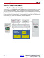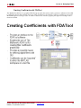
1
System
Generator for
DSP
Getting Started Guide
UG639 (v 14.3) October 16, 2012
This document applies to the following software versions: ISE Design Suite 14.3 through 14.5
Xilinx is disclosing this user guide, manual, release note, and/or specification (the "Documentation") to you solely for use in the development
of designs to operate with Xilinx hardware devices. You may not reproduce, distribute, republish, download, display, post, or transmit the
Documentation in any form or by any means including, but not limited to, electronic, mechanical, photocopying, recording, or otherwise,
without the prior written consent of Xilinx. Xilinx expressly disclaims any liability arising out of your use of the Documentation. Xilinx reserves
the right, at its sole discretion, to change the Documentation without notice at any time. Xilinx assumes no obligation to correct any errors
contained in the Documentation, or to advise you of any corrections or updates. Xilinx expressly disclaims any liability in connection with
technical support or assistance that may be provided to you in connection with the Information.
THE DOCUMENTATION IS DISCLOSED TO YOU “AS-IS” WITH NO WARRANTY OF ANY KIND. XILINX MAKES NO OTHER
WARRANTIES, WHETHER EXPRESS, IMPLIED, OR STATUTORY, REGARDING THE DOCUMENTATION, INCLUDING ANY
WARRANTIES OF MERCHANTABILITY, FITNESS FOR A PARTICULAR PURPOSE, OR NONINFRINGEMENT OF THIRD-PARTY
RIGHTS. IN NO EVENT WILL XILINX BE LIABLE FOR ANY CONSEQUENTIAL, INDIRECT, EXEMPLARY, SPECIAL, OR INCIDENTAL
DAMAGES, INCLUDING ANY LOSS OF DATA OR LOST PROFITS, ARISING FROM YOUR USE OF THE DOCUMENTATION.
© Copyright 2006 - 2012. Xilinx, Inc. XILINX, the Xilinx logo, Artix, ISE, Kintex, Spartan, Virtex, and other designated brands included herein
are trademarks of Xilinx in the United States and other countries. All other trademarks are the property of their respective owners.
System Generator for DSP Getting Started Guide
www.xilinx.com
UG639 (v 14.3) October 16, 2012
Table of Contents
Chapter 1: Introduction
The Xilinx DSP Block Set . . . . . . . . . . . . . . . . . . . . . . . . . . . . . . . . . . . . . . . . . . . . . . . . . . . . 8
FIR Filter Generation . . . . . . . . . . . . . . . . . . . . . . . . . . . . . . . . . . . . . . . . . . . . . . . . . . . . . . . . . 9
Support for MATLAB . . . . . . . . . . . . . . . . . . . . . . . . . . . . . . . . . . . . . . . . . . . . . . . . . . . . . . . 10
System Resource Estimation . . . . . . . . . . . . . . . . . . . . . . . . . . . . . . . . . . . . . . . . . . . . . . . . . 11
Hardware Co-Simulation . . . . . . . . . . . . . . . . . . . . . . . . . . . . . . . . . . . . . . . . . . . . . . . . . . . . 12
System Integration Platform . . . . . . . . . . . . . . . . . . . . . . . . . . . . . . . . . . . . . . . . . . . . . . . . . 13
Chapter 2: Installation
Downloading . . . . . . . . . . . . . . . . . . . . . . . . . . . . . . . . . . . . . . . . . . . . . . . . . . . . . . . . . . . . . . . 15
Hardware Co-Simulation Support . . . . . . . . . . . . . . . . . . . . . . . . . . . . . . . . . . . . . . . . . . 15
UNC Paths Not Supported . . . . . . . . . . . . . . . . . . . . . . . . . . . . . . . . . . . . . . . . . . . . . . . . . 15
Using the ISE Design Suite Installer . . . . . . . . . . . . . . . . . . . . . . . . . . . . . . . . . . . . . . . . . 16
Choosing MATLAB for System Generator . . . . . . . . . . . . . . . . . . . . . . . . . . . . . . . . . . . . 16
Post Installation Tasks . . . . . . . . . . . . . . . . . . . . . . . . . . . . . . . . . . . . . . . . . . . . . . . . . . . . . . 17
Post-Installation Tasks on Linux . . . . . . . . . . . . . . . . . . . . . . . . . . . . . . . . . . . . . . . . . . . .
Troubleshooting a Linux Installation . . . . . . . . . . . . . . . . . . . . . . . . . . . . . . . . . . . . . . . .
Hardware Co-Simulation Installation . . . . . . . . . . . . . . . . . . . . . . . . . . . . . . . . . . . . . . . .
Compiling Xilinx HDL Libraries . . . . . . . . . . . . . . . . . . . . . . . . . . . . . . . . . . . . . . . . . . . .
Configuring the System Generator Cache . . . . . . . . . . . . . . . . . . . . . . . . . . . . . . . . . . . .
Displaying and Changing Versions of System Generator . . . . . . . . . . . . . . . . . . . . . . .
17
17
18
19
19
20
Chapter 3: Release Information
Chapter 4: Getting Started
Introduction . . . . . . . . . . . . . . . . . . . . . . . . . . . . . . . . . . . . . . . . . . . . . . . . . . . . . . . . . . . . . . . . 23
Lesson 1 - Design Creation Basics . . . . . . . . . . . . . . . . . . . . . . . . . . . . . . . . . . . . . . . . . . . 24
The System Generator Design Flow . . . . . . . . . . . . . . . . . . . . . . . . . . . . . . . . . . . . . . . . .
The Xilinx DSP Blockset . . . . . . . . . . . . . . . . . . . . . . . . . . . . . . . . . . . . . . . . . . . . . . . . . . .
Defining the FPGA Boundary . . . . . . . . . . . . . . . . . . . . . . . . . . . . . . . . . . . . . . . . . . . . . .
Adding the System Generator Token . . . . . . . . . . . . . . . . . . . . . . . . . . . . . . . . . . . . . . . .
Creating the DSP Design . . . . . . . . . . . . . . . . . . . . . . . . . . . . . . . . . . . . . . . . . . . . . . . . . . .
Generating the HDL Code . . . . . . . . . . . . . . . . . . . . . . . . . . . . . . . . . . . . . . . . . . . . . . . . .
Model-Based Design using System Generator . . . . . . . . . . . . . . . . . . . . . . . . . . . . . . . .
Creating Input Vectors using MATLAB . . . . . . . . . . . . . . . . . . . . . . . . . . . . . . . . . . . . . .
Lesson 1 Summary . . . . . . . . . . . . . . . . . . . . . . . . . . . . . . . . . . . . . . . . . . . . . . . . . . . . . . . .
Lab Exercise: Using Simulink . . . . . . . . . . . . . . . . . . . . . . . . . . . . . . . . . . . . . . . . . . . . . . .
Lab Exercise: Getting Started with System Generator . . . . . . . . . . . . . . . . . . . . . . . . . .
24
25
26
27
28
29
30
31
32
32
32
Lesson 2 - Fixed Point and Bit Operations . . . . . . . . . . . . . . . . . . . . . . . . . . . . . . . . . . . . 33
Fixed-Point Numeric Precision . . . . . . . . . . . . . . . . . . . . . . . . . . . . . . . . . . . . . . . . . . . . .
System Generator Fixed-Point Quantization . . . . . . . . . . . . . . . . . . . . . . . . . . . . . . . . . .
Overflow and Round Modes . . . . . . . . . . . . . . . . . . . . . . . . . . . . . . . . . . . . . . . . . . . . . . .
Bit-Level Operations . . . . . . . . . . . . . . . . . . . . . . . . . . . . . . . . . . . . . . . . . . . . . . . . . . . . . .
System Generator for DSP Getting Started Guide
UG639 (v 14.3) October 16, 2012
www.xilinx.com
33
34
35
36
3
The Reinterpret Block . . . . . . . . . . . . . . . . . . . . . . . . . . . . . . . . . . . . . . . . . . . . . . . . . . . . .
The Convert Block . . . . . . . . . . . . . . . . . . . . . . . . . . . . . . . . . . . . . . . . . . . . . . . . . . . . . . . .
The Concat Block . . . . . . . . . . . . . . . . . . . . . . . . . . . . . . . . . . . . . . . . . . . . . . . . . . . . . . . . .
Slice Block . . . . . . . . . . . . . . . . . . . . . . . . . . . . . . . . . . . . . . . . . . . . . . . . . . . . . . . . . . . . . . .
The BitBasher Block . . . . . . . . . . . . . . . . . . . . . . . . . . . . . . . . . . . . . . . . . . . . . . . . . . . . . . .
Lesson 2 Summary . . . . . . . . . . . . . . . . . . . . . . . . . . . . . . . . . . . . . . . . . . . . . . . . . . . . . . . .
Lab Exercise: Signal Routing . . . . . . . . . . . . . . . . . . . . . . . . . . . . . . . . . . . . . . . . . . . . . . .
37
38
39
40
41
42
42
Lesson 3 - System Control . . . . . . . . . . . . . . . . . . . . . . . . . . . . . . . . . . . . . . . . . . . . . . . . . . . 43
Controlling a DSP System . . . . . . . . . . . . . . . . . . . . . . . . . . . . . . . . . . . . . . . . . . . . . . . . . .
The MCode Block . . . . . . . . . . . . . . . . . . . . . . . . . . . . . . . . . . . . . . . . . . . . . . . . . . . . . . . . .
The Xilinx “xl_state” Data Type . . . . . . . . . . . . . . . . . . . . . . . . . . . . . . . . . . . . . . . . . . . .
State Machine Example . . . . . . . . . . . . . . . . . . . . . . . . . . . . . . . . . . . . . . . . . . . . . . . . . . . .
The Expression Block . . . . . . . . . . . . . . . . . . . . . . . . . . . . . . . . . . . . . . . . . . . . . . . . . . . . . .
Reset and Enable Ports . . . . . . . . . . . . . . . . . . . . . . . . . . . . . . . . . . . . . . . . . . . . . . . . . . . .
Bursty Data . . . . . . . . . . . . . . . . . . . . . . . . . . . . . . . . . . . . . . . . . . . . . . . . . . . . . . . . . . . . . .
Lesson 3 Summary . . . . . . . . . . . . . . . . . . . . . . . . . . . . . . . . . . . . . . . . . . . . . . . . . . . . . . . .
Lab Exercise: System Control . . . . . . . . . . . . . . . . . . . . . . . . . . . . . . . . . . . . . . . . . . . . . . .
43
44
45
46
47
48
49
50
50
Lesson 4 - Multi-Rate Systems . . . . . . . . . . . . . . . . . . . . . . . . . . . . . . . . . . . . . . . . . . . . . . . 51
Creating Multi-Rate Systems . . . . . . . . . . . . . . . . . . . . . . . . . . . . . . . . . . . . . . . . . . . . . . .
Up and Down Sampling Blocks . . . . . . . . . . . . . . . . . . . . . . . . . . . . . . . . . . . . . . . . . . . . .
Rate Changing Functional Blocks . . . . . . . . . . . . . . . . . . . . . . . . . . . . . . . . . . . . . . . . . . .
Viewing Rate Changes in Simulink . . . . . . . . . . . . . . . . . . . . . . . . . . . . . . . . . . . . . . . . . .
Debugging Tools . . . . . . . . . . . . . . . . . . . . . . . . . . . . . . . . . . . . . . . . . . . . . . . . . . . . . . . . .
Sample Period “Rules” . . . . . . . . . . . . . . . . . . . . . . . . . . . . . . . . . . . . . . . . . . . . . . . . . . . .
Lab Exercise: Multi-Rate Systems . . . . . . . . . . . . . . . . . . . . . . . . . . . . . . . . . . . . . . . . . . .
51
52
53
54
55
56
57
Lesson 5 - Using Memories . . . . . . . . . . . . . . . . . . . . . . . . . . . . . . . . . . . . . . . . . . . . . . . . . . 58
Block vs. Distributed RAM . . . . . . . . . . . . . . . . . . . . . . . . . . . . . . . . . . . . . . . . . . . . . . . . .
Initializing RAMs and ROMs . . . . . . . . . . . . . . . . . . . . . . . . . . . . . . . . . . . . . . . . . . . . . . .
System Generator RAM Blocks . . . . . . . . . . . . . . . . . . . . . . . . . . . . . . . . . . . . . . . . . . . . .
System Generator ROM Blocks . . . . . . . . . . . . . . . . . . . . . . . . . . . . . . . . . . . . . . . . . . . . .
The Delay Block . . . . . . . . . . . . . . . . . . . . . . . . . . . . . . . . . . . . . . . . . . . . . . . . . . . . . . . . . .
The FIFO Block . . . . . . . . . . . . . . . . . . . . . . . . . . . . . . . . . . . . . . . . . . . . . . . . . . . . . . . . . . .
Shared Memory Block . . . . . . . . . . . . . . . . . . . . . . . . . . . . . . . . . . . . . . . . . . . . . . . . . . . . .
Lab Exercise: Using Memories . . . . . . . . . . . . . . . . . . . . . . . . . . . . . . . . . . . . . . . . . . . . . .
58
59
60
61
62
63
64
65
Lesson 6 - Designing Filters . . . . . . . . . . . . . . . . . . . . . . . . . . . . . . . . . . . . . . . . . . . . . . . . . 66
Introduction . . . . . . . . . . . . . . . . . . . . . . . . . . . . . . . . . . . . . . . . . . . . . . . . . . . . . . . . . . . . .
The Virtex DSP48 Math Slice . . . . . . . . . . . . . . . . . . . . . . . . . . . . . . . . . . . . . . . . . . . . . . .
FIR Compiler Block . . . . . . . . . . . . . . . . . . . . . . . . . . . . . . . . . . . . . . . . . . . . . . . . . . . . . . .
Creating Coefficients with FDATool . . . . . . . . . . . . . . . . . . . . . . . . . . . . . . . . . . . . . . . . .
Using FDA Tool Coefficients . . . . . . . . . . . . . . . . . . . . . . . . . . . . . . . . . . . . . . . . . . . . . . .
Lab Exercise: Designing Filters . . . . . . . . . . . . . . . . . . . . . . . . . . . . . . . . . . . . . . . . . . . . .
66
67
68
69
70
71
Additional Examples and Tutorials . . . . . . . . . . . . . . . . . . . . . . . . . . . . . . . . . . . . . . . . . . 72
AXI4 Conversion Examples . . . . . . . . . . . . . . . . . . . . . . . . . . . . . . . . . . . . . . . . . . . . . . . .
Black Box Examples . . . . . . . . . . . . . . . . . . . . . . . . . . . . . . . . . . . . . . . . . . . . . . . . . . . . . . .
ChipScope Examples . . . . . . . . . . . . . . . . . . . . . . . . . . . . . . . . . . . . . . . . . . . . . . . . . . . . . .
DSP Examples . . . . . . . . . . . . . . . . . . . . . . . . . . . . . . . . . . . . . . . . . . . . . . . . . . . . . . . . . . . .
M-Code Examples . . . . . . . . . . . . . . . . . . . . . . . . . . . . . . . . . . . . . . . . . . . . . . . . . . . . . . . .
Processor Examples . . . . . . . . . . . . . . . . . . . . . . . . . . . . . . . . . . . . . . . . . . . . . . . . . . . . . . .
Shared Memory Examples . . . . . . . . . . . . . . . . . . . . . . . . . . . . . . . . . . . . . . . . . . . . . . . . .
Miscellaneous Examples . . . . . . . . . . . . . . . . . . . . . . . . . . . . . . . . . . . . . . . . . . . . . . . . . . .
System Generator Demos . . . . . . . . . . . . . . . . . . . . . . . . . . . . . . . . . . . . . . . . . . . . . . . . . .
4
www.xilinx.com
72
72
73
73
74
75
75
76
77
System Generator for DSP Getting Started Guide
UG639 (v 14.3) October 16, 2012
Index . . . . . . . . . . . . . . . . . . . . . . . . . . . . . . . . . . . . . . . . . . . . . . . . . . . . . . . . . . . . . . . . . . . . . . . . . . . .
System Generator for DSP Getting Started Guide
UG639 (v 14.3) October 16, 2012
www.xilinx.com
79
5
6
www.xilinx.com
System Generator for DSP Getting Started Guide
UG639 (v 14.3) October 16, 2012
Chapter 1
Introduction
System Generator is a DSP design tool from Xilinx that enables the use of the MathWorks
model-based Simulink® design environment for FPGA design. Previous experience with
Xilinx FPGAs or RTL design methodologies are not required when using System
Generator. Designs are captured in the DSP friendly Simulink modeling environment
using a Xilinx specific blockset. All of the downstream FPGA implementation steps
including synthesis and place and route are automatically performed to generate an FPGA
programming file.
System Generator for DSP Getting Started Guide
UG639 (v 14.3) October 16, 2012
www.xilinx.com
7
Chapter 1: Introduction
The Xilinx DSP Block Set
Over 90 DSP building blocks are provided in the Xilinx DSP blockset for Simulink. These
blocks include the common DSP building blocks such as adders, multipliers and registers.
Also included are a set of complex DSP building blocks such as forward error correction
blocks, FFTs, filters and memories. These blocks leverage the Xilinx IP core generators to
deliver optimized results for the selected device.
8
www.xilinx.com
System Generator for DSP Getting Started Guide
UG639 (v 14.3) October 16, 2012
FIR Filter Generation
FIR Filter Generation
System Generator includes a FIR Compiler block that targets the dedicated DSP48
hardware resources in the Virtex®-4 and Virtex-5 devices to create highly optimized
implementations that can run in excess of 500 Mhz. Configuration options allow
generation of direct, polyphase decimation, polyphase interpolation and oversampled
implementations. Standard MATLAB functions such as fir2 or the MathWorks FDAtool
can be used to create coefficients for the Xilinx FIR Compiler.
System Generator for DSP Getting Started Guide
UG639 (v 14.3) October 16, 2012
www.xilinx.com
9
Chapter 1: Introduction
Support for MATLAB
Included in System Generator is an MCode block that allows the use of non-algorithmic
MATLAB for the modeling and implementation of simple control operations.
10
www.xilinx.com
System Generator for DSP Getting Started Guide
UG639 (v 14.3) October 16, 2012
System Resource Estimation
System Resource Estimation
System Generator provides a Resource Estimator block that quickly estimates the area of a
design prior to place and route. This can be a valuable aid in the hardware / software
partitioning process by helping system designers take full advantage of the FPGA
resources which include up to 640 multiply/accumulate (or DSP) blocks in the Virtex®-5
devices.
System Generator for DSP Getting Started Guide
UG639 (v 14.3) October 16, 2012
www.xilinx.com
11
Chapter 1: Introduction
Hardware Co-Simulation
System Generator provides accelerated simulation through hardware co-simulation.
System Generator will automatically create a hardware simulation token for a design
captured in the Xilinx DSP blockset that will run on one of over 20 supported hardware
platforms. This hardware will co-simulate with the rest of the Simulink system to provide
up to a 1000x simulation performance increase.
12
www.xilinx.com
System Generator for DSP Getting Started Guide
UG639 (v 14.3) October 16, 2012
System Integration Platform
System Integration Platform
System Generator provides a system integration platform for the design of DSP FPGAs
that allows the RTL, Simulink, MATLAB and C/C++ components of a DSP system to come
together in a single simulation and implementation environment. System Generator
supports a black box block that allows RTL to be imported into Simulink and co-simulated
with either ModelSim or Xilinx® ISE® Simulator. System Generator also supports the
inclusion of a MicroBlaze® embedded processor running C/C++ programs.
System Generator for DSP Getting Started Guide
UG639 (v 14.3) October 16, 2012
www.xilinx.com
13
Chapter 1: Introduction
14
www.xilinx.com
System Generator for DSP Getting Started Guide
UG639 (v 14.3) October 16, 2012
Chapter 2
Installation
Downloading
System Generator is part of the ISE® Design Suite and may be download from the Xilinx
web page. You may purchase, register, and download the System Generator software from
the site at:
http://www.xilinx.com/tools/sysgen.htm
Note: In special circumstances, System Generator can be delivered on a CD. Please contact your
Xilinx distributor if your circumstances prohibit you from downloading the software via the web.
Hardware Co-Simulation Support
If you have an FPGA development board, you may be able to take advantage of System
Generator’s ability to use FPGA hardware co-simulation with Simulink simulations. The
System Generator software includes support for the XtremeDSP Development Kit, the
MicroBlaze™ Multimedia Demonstration boards, the MVI hardware platform, the ML402
Virtex®-4 Board, the ML506 Virtex-5 Board, the ML605 Virtex-6 Board, the Spartan-3A DSP
1800 Starter Board, the Spartan-3A DSP 3400 Development Board, and the Spartan-6
SP601/SP605 Board. Additional System Generator board support packages provide
support for additional hardware co-simulation boards. System Generator board support
packages can be downloaded from the following URL:
http://www.xilinx.com/products/boards_kits/index.htm
UNC Paths Not Supported
System Generator does not support UNC (Universal Naming Convention) paths. For
example System Generator cannot operate on a design that is located on a shared network
drive without mapping to the drive first.
System Generator for DSP Getting Started Guide
UG639 (v 14.3) October 16, 2012
www.xilinx.com
15
Chapter 2: Installation
Using the ISE Design Suite Installer
System Generator for DSP is part of the Xilinx ISE® Design Suite and you must use the ISE
Design Suite installer to install System Generator.
Before invoking the ISE Design Suite installer, it is a good idea to make sure that all
instances of MATLAB are closed. When all instances of MATLAB are closed, launch the
installer and follow the directions on the screen.
Choosing MATLAB for System Generator
Windows Installations
This dialog box allows you to associate any supported MATLAB installation with this
version of System Generator.
Click the check box of the MATLAB installation(s) you wish to associate with this version
of System Generator, select the Xilinx Design Suite you wish to associate with, then click
Apply. Once the Apply operation is completed, the value in the Status column changes
from “Not Configured” to “Configured”.
The application lists all the available MATLAB installations. The Status field shows one of
the following values:
Unsupported: This version of MATLAB is not supported with this version of System
Generator.
Not Configured: This version of MATLAB is not yet associated with this version of System
Generator. To associate this version of MATLAB with System Generator, click the check
box and then click Apply.
Configured: System Generator is now ready to be used with this version of MATLAB.
If you don’t see a version of MATLAB listed, click Find MATLAB to browse for a valid
version.
If you wish to change the MATLAB configuration, select the following Windows menu
item:
Start > All Programs > Xilinx Design Tools > ISE Design Suite > System Generator >
System Generator MATLAB Configurator.
16
www.xilinx.com
System Generator for DSP Getting Started Guide
UG639 (v 14.3) October 16, 2012
Post Installation Tasks
If MATLAB is configured for a Design Suite, say IDS, and you wish to re-configure
MATLAB for another Design Suite, say Vivado, you must select the Configured MATLAB
version box and click Remove before you re-configure for Vivado.
Linux Installations
Launching System Generator under Linux is handled via a shell script called “sysgen”
located in the <IDS install dir>/sysgen/util directory. Since System Generator supports
both ISE and Vivado, a command line option has been made available to subscribe to the
Vivado specific blockset(s) supported by System Generator. Without any command line
arguments, System Generator will use ISE supported blockset(s) within MATLAB.Using
the ‘-v’ option forces System Generator into Vivado mode. When MATLAB opens, text
detailing which blockset(s) will be shown as below will be to indicate which version of the
tool suite is used.
Using Vivado enabled System Generator
or
Using ISE enabled System Generator
This message on the MATLAB console will be seen as part of the dynamic installation of
System Generator into MATLAB.
Post Installation Tasks
Post-Installation Tasks on Linux
After following the directions of the main ISE Design Suite Installation Wizard, you are
ready to launch System Generator by typing: sysgen
Note: This will invoke MATLAB and dynamically add System Generator to that MATLAB session. At
the top of the MATLAB Command Window, you should see the “Installed System Generator
dynamically” messages. You are now ready to run System Generator.
The following is an expected message under certain conditions. If System Generator is
already installed when this script runs, you will see the following message:
System Generator currently found installed into matlab
default path.
Troubleshooting a Linux Installation
The following four functions are used to troubleshoot and verify the Linux Installation.
xl_get_matlab_support_xmlfile
This MATLAB function will retrieve the expected location of the common XML file
used for determining MATLAB support within System Generator.
xl_verify_matlab_support_xmlfile <pathname_to_xmlfile>
This matlab function will verify that the specified XML file exists and is readable. If no
XML file exists, the following error message is thrown to the MATLAB console”
System Generator for DSP Getting Started Guide
UG639 (v 14.3) October 16, 2012
www.xilinx.com
17
Chapter 2: Installation
Could not find ml_supported.xml to determine supported versions
of MATLAB with System Generator.
If the XML file is unreadable, the error message that is thrown to the MATLAB console
is:
Could not read ml_supported.xml to determine supported versions
of MATLAB with System Generator
xl_read_matlab_support_xmlfile
This MATLAB function reads and parses the XML file looking for the supported
MATLAB version information and provides error/warning messages used by the
sysgen_startup.m script.
xl_test_matlab_support_xmlfile
This MATLAB function tests the current instantiated MATLAB session and compares
its version to those which are supported. Errors or warnings will be displayed based
on results of this comparison. If the XML file is devoid of information, the error thrown
to the MATLAB console is as folows:
Matlab support table used by System Generator is empty!
If the XML file information does not conform to the expected format, the following
error is thrown to the MATLAB console:
Input matlab support table is not well formed.
only 2 columns!
It should have
If you are using a version of MATLAB that is too old (unsupported), then you will see
the following error messages:
System Generator will not properly function under this version
of MATLAB!
Error occurred while attempting to install System Generator into
MATLAB path.
If you are using a version of MATLAB that is too new, then you will see the following
warning messages:
System Generator may not properly function under this version of
MATLAB!
Hardware Co-Simulation Installation
This topic provides links to hardware and software installation procedures for hardware
co-simulation. If you do not plan to use hardware co-simulation, you may skip this topic.
Ethernet-Based Hardware Co-Simulation
Installing an ML402 Board for Ethernet Hardware Co-Simulation
Installing an ML560 Board for Ethernet Hardware Co-Simulation
Installing an ML650 Board for Ethernet Hardware Co-Simulation
Installing a Spartan-3A DSP 1800A Starter Board for Ethernet Hardware Co-Simulation
Installing a Spartan-3A DSP 3400A Development Board for Ethernet Hardware CoSimulation
18
www.xilinx.com
System Generator for DSP Getting Started Guide
UG639 (v 14.3) October 16, 2012
Post Installation Tasks
Installing an SP601/SP605 Board for Ethernet Hardware Co-Simulation
Note: If installation instructions for your particular platform are not provided here, please refer to the
installation instuctions that come with your Platform Kit. For instructions on how to install a Xilinx USB
Cable and cable driver software on a Windows or Linux Operating System, refer to the Xilinx
document titled: USB Cable Installation Guide
JTAG-Based Hardware Co-Simulation
Installing an ML402 Board for JTAG Hardware Co-Simulation
Installing an ML605 Board for JTAG Hardware Co-Simulation
Installing an SP601/SP605 Board for JTAG Hardware Co-Simulation
Installing a KC705 Board for JTAG Hardware Co-Simulation
Third-Party Hardware Co-Simulation
As part of the Xilinx XtremeDSP™ Initiative, Xilinx works with distributors and many
OEMs to provide a variety of DSP prototyping and development platforms. Please refer to
the following Xilinx web site page for more information on available platforms:
http://www.xilinx.com/products/boards_kits/index.htm
Compiling Xilinx HDL Libraries
If you intend to simulate System Generator designs using ModelSim, you must compile
your IP (cores) libraries. This topic describes the procedure.
ModelSim SE
The Xilinx tool that compiles libraries for use in ModelSim SE is named compxlib. The
following command can, for example, be used to compile all the VHDL and Verilog
libraries with ModelSim SE:
compxlib –s mti_se –f all –l all
Complete instructions for running compxlib can be found in the ISE Software Manual
titled “Command Line Tool User Guide”.
Configuring the System Generator Cache
Both the System Generator simulator and the design generator incorporate a disk cache to
speed up the iterative design process. The cache does this by tagging and storing files
related to simulation and generation, then recalling those files during subsequent
simulation and generation rather than rerunning the time consuming tools used to create
those files.
Setting the Size
By default, the cache will use up to 500 MB of disk space to store files. To specify the
amount of disk space the cache should use, set the SYSGEN_CACHE_SIZE environment
variable to the size of the cache in megabytes. Set this number to a higher value when
working on several large designs.
System Generator for DSP Getting Started Guide
UG639 (v 14.3) October 16, 2012
www.xilinx.com
19
Chapter 2: Installation
Setting the Number of Entries
The cache entry database stores a fixed number of entries. The default is 20,000 entries. To
set size of the cache entry database, set the SYSGEN_CACHE_ENTRIES environment
variable to the desired number of entries. Setting this number too small will adversely
affect cache performance. Set this number to a higher value when working on several large
designs.
You can use the xlCache function to manage and inspect the properties of difference caches
used by System Generator. A detailed description of this function can be found under the
topic System Generator Utilities.
Displaying and Changing Versions of System Generator
It is possible to have several versions of System Generator installed. The MATLAB
command xlVersion displays which versions are installed, and makes it possible to
switch from one to another. xlVersion is useful when upgrading a model to run in the
latest version of System Generator.
Entering "xlVersion" in the MATLAB console displays the version of System Generator
that is installed.
Available System Generator installations:
Version 14.1.4301 in C:/Xilinx/14.1/ISE_DS/ISE/sysgen
Current version of System Generator is 14.1.4301
20
www.xilinx.com
System Generator for DSP Getting Started Guide
UG639 (v 14.3) October 16, 2012
Chapter 3
Release Information
System Generator for DSP release information can now be found in the following Webbased document:
Xilinx Design Tools: Release Notes Guide
System Generator for DSP Getting Started Guide
UG639 (v 14.3) October 16, 2012
www.xilinx.com
21
Chapter 3: Release Information
22
www.xilinx.com
System Generator for DSP Getting Started Guide
UG639 (v 14.3) October 16, 2012
Chapter 4
Getting Started
Introduction
This Getting Started training consists of six short lessons that introduce you to major
features of System Generator for DSP. Each lesson takes less than 10 minutes to read and is
followed by one or more hands-on lab exercises. The lab exercise folders are located in the
System Generator software tree and contain data files and step-by-step instructions.
If you have System Generator installed on your computer, you can complete each lab
exercise at your own pace and on your own time schedule. If you do not have System
Generator installed, you can access this free training in a recorded e-learning format
through the Xilinx web site at the following location:
http://www.xilinx.com/support/training/rel/system-generator.htm
The lessons contained in this Getting Started are as follows:
•
Lesson 1 - Design Creation Basics: Introduces the basics of creating and
implementing a DSP design using System Generator.
•
Lesson 2 - Fixed Point and Bit Operations: Covers the use of the System Generator
routing blocks for extracting and manipulating the individual bits of a fixed-point
signal.
•
Lesson 3 - System Control: Covers the preferred methods for using System Generator
to create finite state machines, logical control conditions, and the handling of bursty
data typical of FFT and filtering operations.
•
Lesson 4 - Multi-Rate Systems: Shows the proper way to create multi-rate systems
using upsampling and downsampling of data.
•
Lesson 5 - Using Memories: Covers proper usage of the Xilinx block RAM resources
and the DSP blocks available for building DSP designs targeting Xilinx RAMs.
•
Lesson 6 - Designing Filters: Discusses methods for creating efficient FIR filters in the
Xilinx devices, use of the FIR Compiler block for filter implementation, and use of the
FDATool for filter design.
System Generator for DSP Getting Started Guide
UG639 (v 14.3) October 16, 2012
www.xilinx.com
23
Chapter 4: Getting Started
Lesson 1 - Design Creation Basics
The System Generator Design Flow
System Generator works within the Simulink model-based design methodology. Often an executable spec is created
using the standard Simulink block sets. This spec can be designed using floating-point numerical precision and
without hardware detail. Once the functionality and basic dataflow issues have been defined, System Generator can
be used to specify the hardware implementation details for the Xilinx devices. System Generator uses the Xilinx
DSP blockset for Simulink and will automatically invoke Xilinx Core Generator™ to generate highly-optimized
netlists for the DSP building blocks. System Generator can execute all the downstream implementation tools to
product a bitstream for programming the FPGA. An optional testbench can be created using test vectors extracted
from the Simulink environment for use with ModelSim or the Xilinx ISE® Simulator.
24
www.xilinx.com
System Generator for DSP Getting Started Guide
UG639 (v 14.3) October 16, 2012
Lesson 1 - Design Creation Basics
The Xilinx DSP Blockset
The Xilinx DSP blockset is accessed via the Simulink Library browser which can be launched from the standard
MATLAB toolbar. The blocks are separated into sub-categories for easier searching. One sub-category, “Index”
includes all the block and is often the quickest way to access a block you are already familiar with. Over 90 DSP
building blocks are available for constructing you DSP system.
NOTE: It is important that you don’t name your design the same as a Xilinx block. For example, if you name your design
shared_memory.mdl, it may cause System Generator to issue an error message.
Each block has a background color that indicates the following:
Background
Color
Blue
Meaning
Block Goes into the FPGA fabric and is free!!
Green
Block Goes into the FPGA fabric and is a Pay Core/Licensed. Go to the
Xilinx web site to purchase the Core license.
Yellow
Blocks on the boundary of your design like Gateway, Shared Memory
Read, Shared Memory Write, VDMA, etc
White
Utility or Tool
Red Symbol
System Generator Token (control panel)
System Generator for DSP Getting Started Guide
UG639 (v 14.3) October 16, 2012
www.xilinx.com
25
Chapter 4: Getting Started
Defining the FPGA Boundary
System Generator works with standard Simulink models. Two blocks called “Gateway In” and “Gateway Out”
define the boundary of the FPGA from the Simulink simulation model. The Gateway In block converts the floating
point input to a fixed-point number. You double-click on the block to bring up the properties editor which is where
the fixed-point number can be fully specified.
26
www.xilinx.com
System Generator for DSP Getting Started Guide
UG639 (v 14.3) October 16, 2012
Lesson 1 - Design Creation Basics
Adding the System Generator Token
Every System Generator diagram requires that at least one System Generator token be placed on the diagram. This
token is not connected to anything but serves to drive the FPGA implementation process. The property editor for
this token allows you to specify the target netlist, device, performance targets and system period. System Generator
will issue an error if this token is absent.
System Generator for DSP Getting Started Guide
UG639 (v 14.3) October 16, 2012
www.xilinx.com
27
Chapter 4: Getting Started
Creating the DSP Design
Once the FPGA boundaries have been established using the Gateway blocks, the DSP design can be constructed
using blocks from the Xilinx DSP blockset. Standard Simulink blocks are not supported for use within the Gateway
In / Gateway out blocks. You will find a rich set of filters, FFTs, FEC cores, memories, arithmetic, logical and bitwise
blocks available for use in constructing DSP designs. Each of these blocks are cycle and bit accurate.
28
www.xilinx.com
System Generator for DSP Getting Started Guide
UG639 (v 14.3) October 16, 2012
Lesson 1 - Design Creation Basics
Generating the HDL Code
Once the design is completed, the hardware implementation files can be generated using the Generate button
available on the System Generator token properties editor. One option is to select HDL Netlist which allows the
FPGA implementation steps of RTL synthesis and place and route to be performed interactively using tool specific
user interfaces. Alternatively, you can select Bitstream as the Compilation target and System Generator will
automatically perform all implementation steps.
If the Create Testbench option is selected, then System Generator will save and write test vector files that are
extracted from the Simulink simulation and generate an HDL testbench and script files for ModelSim. This is an
optional step that simply verifies that the generated hardware is functionally equivalent to the Simulink simulation.
The script files must be used with ModelSim interactively.
System Generator for DSP Getting Started Guide
UG639 (v 14.3) October 16, 2012
www.xilinx.com
29
Chapter 4: Getting Started
Model-Based Design using System Generator
Model-based design refers the design practice of creating a high-level executable specification using the standard
Simulink blocksets or MATLAB first to define the desired functional behavior with minimal hardware detail. This
executable spec is then used as a reference model while the hardware representation is specified using the Xilinx
DSP blockset.
30
www.xilinx.com
System Generator for DSP Getting Started Guide
UG639 (v 14.3) October 16, 2012
Lesson 1 - Design Creation Basics
Creating Input Vectors using MATLAB
Simulink is built on top of MATLAB allowing the use of the full MATLAB language for input signal generation and
output analysis. You can use the “From Workspace” and “To Workspace” blocks from the Simulink Source and Sink
libraries. Input values must be specified as an n rows x 2 column matrix where the first column is the simulation
time and the second column includes the input values. This is a very popular way to generate input vectors for
System Generator designs.
System Generator for DSP Getting Started Guide
UG639 (v 14.3) October 16, 2012
www.xilinx.com
31
Chapter 4: Getting Started
Lesson 1 Summary
•
You partition the FPGA design from the Simulink “system” using Gateway In /
Gateway Out blocks.
•
You always include a System Generator token on each sheet
•
You should only use blocks from the Xilinx DSP blockset between the gateway blocks
•
You should consider using the From / To workspace blocks to use MATLAB for input
generation and output analysis
Lab Exercise: Using Simulink
In this lab, you will learn the basics of Simulink. You will use a Simulink blockset to
generate a simple design and take it through simulation. You will then change the
sampling settings to see its effect on the output. You will then learn how to create a
subsystem.
The lab instructions are located in the System Generator software tree at the following
pathname:
<ISE_Design_Suite_tree>/sysgen/examples/getting_started_training/lab1/lab
1.pdf
Lab Exercise: Getting Started with System Generator
This lab introduces you to the basic concepts of creating a design using System Generator
within the model-based design flow provided through Simulink. The design is a simple
multiply-add circuit.
The lab instructions and lab design are located in the System Generator software tree at the
following pathname:
<ISE_Design_Suite_tree>/sysgen/examples/getting_started_training/lab2/
32
www.xilinx.com
System Generator for DSP Getting Started Guide
UG639 (v 14.3) October 16, 2012
Lesson 2 - Fixed Point and Bit Operations
Lesson 2 - Fixed Point and Bit Operations
Fixed-Point Numeric Precision
System Generator supports four data types, Unsigned for positive only DSP operations, Signed which is two’s
complement used for DSP operations that involve negative numbers, Boolean for 1-bit control signals and
Floating-Point. Each block will typically have quantization parameters. The initial quantization is defined by the
Gateway In blocks.
System Generator for DSP Getting Started Guide
UG639 (v 14.3) October 16, 2012
www.xilinx.com
33
Chapter 4: Getting Started
System Generator Fixed-Point Quantization
Xilinx fixed-point data types are defined by specifying the total number of bits then specifying the location of the
binary point. The difference, which represents the number of bits to the left of the binary point, are the integer bits
for ufixed numbers and the integer bits plus sign bit for signed numbers. Xilinx FPGAs do not require that fixedpoint numbers fall in pre-defined 8 bit boundaries as is the case with DSP processors. The logic can grow bit-by-bit
to accommodate the required fixed-point precision.
34
www.xilinx.com
System Generator for DSP Getting Started Guide
UG639 (v 14.3) October 16, 2012
Lesson 2 - Fixed Point and Bit Operations
Overflow and Round Modes
System Generator supports the overflow modes Wrap, Saturate and Flag as error. Wrap is the default because it has
the least cost in hardware. Saturate requires System Generator to insert logic to perform that operation and
therefore should only be used when necessary for the application
System Generator supports Truncate and Round of the LSB during the quantization process. Similar to the Wrap
mode for overflow mode, Truncate has minimal hardware cost and is the default. Specifying the Round mode
requires System Generator to insert extra logic and should be used when only necessary for the application.
System Generator for DSP Getting Started Guide
UG639 (v 14.3) October 16, 2012
www.xilinx.com
35
Chapter 4: Getting Started
Bit-Level Operations
In a real DSP hardware system, not all operations can be expressed mathematically. Often a signal must be accessed
by its individual bits. System Generator supports a set of bit-level operations that allow the reinterpret, combining,
conversion and extraction of the individual bits of a signal. This can be used to pad, unpad and slice off the bits of
a signal with a high degree of control. These blocks do not use any hardware resources
36
www.xilinx.com
System Generator for DSP Getting Started Guide
UG639 (v 14.3) October 16, 2012
Lesson 2 - Fixed Point and Bit Operations
The Reinterpret Block
The Reinterpret block forces the bits of a signal to a new type without regard for the numerical value or location of
the decimal point. This block does not change the number of bits of a signal but simply reinterprets the data type.
For example if the number 4 is represented as an unsigned [4 1] it is 1000. If this number is reinterpreted to be
unsigned [4 0], the 1000 is now 8.
System Generator for DSP Getting Started Guide
UG639 (v 14.3) October 16, 2012
www.xilinx.com
37
Chapter 4: Getting Started
The Convert Block
The Convert block changes the quantization of a number but not the value. This block can alter the number of bits
used to represent a number. It can be used to convert a signed type to an unsigned type and visa versa. Often the
Convert block is used to truncate the output fractional bits after a multiplication operation.
38
www.xilinx.com
System Generator for DSP Getting Started Guide
UG639 (v 14.3) October 16, 2012
Lesson 2 - Fixed Point and Bit Operations
The Concat Block
The Concat block concatenates two inputs into a single output at the bit level. This block has two input ports that
are labeled hi and lo. The hi port occupies the MSB’s and the lo input occupies the LSB’s of the output signal.
This block is useful for zero padding the MSBs or LSBs of a signal.
System Generator for DSP Getting Started Guide
UG639 (v 14.3) October 16, 2012
www.xilinx.com
39
Chapter 4: Getting Started
Slice Block
The Slice block is used to access individual bits of a quantized number. This block provides several mechanisms by
which the sequence of bits can be specified. If the input type is known at the time of parameterization, the various
mechanisms do not offer any gain in functionality. If, however, a Slice block is used in a design where the input data
width or binary point position are subject to change, the variety of mechanisms becomes useful. For example, the
block can be configured to always extract only the top bit of the input, or only the integer bits, or only the first three
fractional bits.
40
www.xilinx.com
System Generator for DSP Getting Started Guide
UG639 (v 14.3) October 16, 2012
Lesson 2 - Fixed Point and Bit Operations
The BitBasher Block
The BitBasher block provides a textual method, based on Verilog syntax, for working with the signals at the bit
level. This block supports concatenation and slicing if the input signal to create an output. It also allows for
augmentation with constants. The BitBasher block supports up to 4 outputs that are inferred by the expressions
System Generator for DSP Getting Started Guide
UG639 (v 14.3) October 16, 2012
www.xilinx.com
41
Chapter 4: Getting Started
Lesson 2 Summary
•
Quantization and overflow options are available when the output of a block is user
defined
•
Quantization occurs when the number of fractional bits is insufficient to represent the
fractional portion of a value
•
Overflow occurs when a value lies outside the representable range
•
Bit picking blocks allow combining of multiple buses into a single bus, force a
conversion of data type without changing the number of bits, extract bits, and convert
the number into different format
•
The BitBasher block allows bit manipulation and augmentation through textual
specification based in Verilog
Lab Exercise: Signal Routing
In this lab you will design and verify padding and unpadding logic using the System
Generator signal routing blocks
The lab instructions are located in the System Generator software tree at the following
pathname:
<ISE_Design_Suite_tree>/sysgen/examples/getting_started_training/lab3/lab
3.pdf
42
www.xilinx.com
System Generator for DSP Getting Started Guide
UG639 (v 14.3) October 16, 2012
Lesson 3 - System Control
Lesson 3 - System Control
Controlling a DSP System
When you develop a DSP system in hardware, some level of control is usually required. This may include state
dependent behavior or simply performing operations such as filter coefficient updating. System-level control may
also be needed for controlling bursty data such as non-streaming FFTs.
System Generator for DSP Getting Started Guide
UG639 (v 14.3) October 16, 2012
www.xilinx.com
43
Chapter 4: Getting Started
The MCode Block
The MCode block supports the use of MATLAB for implementing state dependent and branch conditional control
operations. This block is not suitable for MATLAB that describes an algorithmic operation such as a FIR filter or
Matrix inverse. The MCode block provides a convenient and efficient method for implementing state machines and
complex muxing conditions. This is the recommended way to implement a finite state machine in System
Generator.
44
www.xilinx.com
System Generator for DSP Getting Started Guide
UG639 (v 14.3) October 16, 2012
Lesson 3 - System Control
The Xilinx “xl_state” Data Type
When implementing a state machine using the MCode block, a Xilinx-provided MATLAB function called “xl_state”
must be used to initialize a persistent variable. This function has two arguments, the first is the initial condition, the
second is the quantization of the assigned variable. For example, if your state machine has 6 states, you need a
quantization of 4-bits unsigned.
System Generator for DSP Getting Started Guide
UG639 (v 14.3) October 16, 2012
www.xilinx.com
45
Chapter 4: Getting Started
State Machine Example
The figure below shows a simple 2-state FSM. This can be easily extended to more states. Notice that a variable
called “state” is declared to be persistent and is initialized to 2 bits, unsigned using the “xl_state” function. A
switch-case statement is then used to decode the inputs, branch to the next state and assign the outputs.
46
www.xilinx.com
System Generator for DSP Getting Started Guide
UG639 (v 14.3) October 16, 2012
Lesson 3 - System Control
The Expression Block
The Expression block performs a bitwise not, and, or & xor on two input signals. The inputs can have a word length
greater than 1. In cases where the two inputs have different word lengths, the binary points are matched up and
then an element-by-element boolean operation is performed. This block provides a useful way to implement logical
control in a DSP system
System Generator for DSP Getting Started Guide
UG639 (v 14.3) October 16, 2012
www.xilinx.com
47
Chapter 4: Getting Started
Reset and Enable Ports
Most System Generator blocks that include memory or storage provide options to expose the reset and clock enable
ports. If un-selected, these ports are automatically connected to the final hardware's global reset and clock enable or
DCM schemes. Exposing these ports on the System Generator block creates a condition where the block is reset or
enabled when either the global signals or the local signals assert TRUE. You should use these ports if greater control
over these functions is required in the DSP system.
48
www.xilinx.com
System Generator for DSP Getting Started Guide
UG639 (v 14.3) October 16, 2012
Lesson 3 - System Control
Bursty Data
Several of the more complex DSP blocks offered in the Xilinx DSP blockset result in “bursty” data. For example, the
non-streaming FFT requires several clock cycles to process the input data prior to generating valid output data. In
these cases, these blocks include data flow control ports that must be used in the DSP system. These ports provide
basic push mode dataflow control. They consist of a vin port which indicates that valid data is available at the
inputs and vout which indicates that valid data is available at the outputs.
System Generator for DSP Getting Started Guide
UG639 (v 14.3) October 16, 2012
www.xilinx.com
49
Chapter 4: Getting Started
Lesson 3 Summary
•
Use the MCode block for state machines and branch conditional logic
•
Use the Expression block to implement logical control at the bit level
•
Storage elements have the ability to include optional reset and clock enable pins that
can be connected in System Generator
•
Blocks that operate on bursty data include data flow control pins called vin and vout
Lab Exercise: System Control
In this lab you will be creating a simple state machine using the MCode block to detect a
sequence of binary values “1011”. The FSM needs to be able to detect multiple
transmissions as well, i.e., “10111011”
The lab data and instructions are located in the System Generator software tree at the
following pathname:
<ISE_Design_Suite_tree>/sysgen/examples/getting_started_training/lab4/
50
www.xilinx.com
System Generator for DSP Getting Started Guide
UG639 (v 14.3) October 16, 2012
Lesson 4 - Multi-Rate Systems
Lesson 4 - Multi-Rate Systems
Creating Multi-Rate Systems
The following illustration shows a typical base-station receiver. The tower has multiple antennas to provide
sectored coverage of the area. The diagram shows that this results in two receiver channels. In each of these
channels, there is some form of complex mixing, resulting in real and imaginary channels.
Often DSP systems such as this will down sample the input signals prior to the digital filtering steps performed
during equalization and demodulation. Doing so can simplify the filter design and hardware significantly. These
systems are referred to as “multi-rate” systems
System Generator for DSP Getting Started Guide
UG639 (v 14.3) October 16, 2012
www.xilinx.com
51
Chapter 4: Getting Started
Up and Down Sampling Blocks
System Generator includes Up Sample and Down Sample blocks that change the system sample rate. The Up
Sample block adds additional samples to the signal to achieve the desired rate change. The value of these new
samples is either zero or the value of the last actual sample depending on the block options. The Down Sample
block simply discards samples until it achieves the desired rate change. For example, downsample by 3 means to
discard 2 out of every 3 samples.
52
www.xilinx.com
System Generator for DSP Getting Started Guide
UG639 (v 14.3) October 16, 2012
Lesson 4 - Multi-Rate Systems
Rate Changing Functional Blocks
In addition to the straightforward “Up Sample” and “Down Sample” blocks, System Generator also provides rate
changing functional blocks; that is blocks that also perform a specific function. The Parallel to Serial block will up
sample, the Serial to Parallel block will down sample, the FIR Compiler, if using a resource-shared multiplier will
down sample and the TDM block will up sample.
System Generator for DSP Getting Started Guide
UG639 (v 14.3) October 16, 2012
www.xilinx.com
53
Chapter 4: Getting Started
Viewing Rate Changes in Simulink
Simulink supports viewing different sample times as different colors which is fully supported for System Generator
blocks. To enable the Sample Time Colors feature, select the pulldown menu Format > Sample Time Colors. The
Simulink tool does not automatically recolor the model with each change you make to it, so you must select Edit >
Update Diagram to explicitly update the model coloration. To return to your original coloring, disable the sample
time coloration by, again, choosing Sample Time Colors.
54
www.xilinx.com
System Generator for DSP Getting Started Guide
UG639 (v 14.3) October 16, 2012
Lesson 4 - Multi-Rate Systems
Debugging Tools
System Generator provides 3 debugging utilities to assist in debugging complex multi-rate systems.
The Sample Time (ST) probe can be connected to any System Generator signal then to a Simulink “display” block
from the “Sinks” library. The sample time for the connected net will appear in the display.
The clk probe is not connected to any inputs but only to a scope output. It displays the master clock. This can be
used with the Clock Enable Probe to display the behavior of the clock enable signal at various points in the down
sampling
System Generator for DSP Getting Started Guide
UG639 (v 14.3) October 16, 2012
www.xilinx.com
55
Chapter 4: Getting Started
Sample Period “Rules”
The illustration below is an example of a multi-rate system that demonstrates how the Simulink System Period can
be calculated and entered into the System Generator token GUI.
If you get it wrong, there is a sampling period analyzer that automatically determines the appropriate sample
period and prompts you to update the GUI.
56
www.xilinx.com
System Generator for DSP Getting Started Guide
UG639 (v 14.3) October 16, 2012
Lesson 4 - Multi-Rate Systems
Lab Exercise: Multi-Rate Systems
In this lab you will be exploring the effects of the rate changing blocks available in System
Generator. These blocks include Upsample, Downsample, Serial to Parallel and Parallel to
Serial.
The lab instructions and lab design are located in the System Generator software tree at the
following pathname:
<ISE_Design_Suite_tree>/sysgen/examples/getting_started_training/lab5/
System Generator for DSP Getting Started Guide
UG639 (v 14.3) October 16, 2012
www.xilinx.com
57
Chapter 4: Getting Started
Lesson 5 - Using Memories
Block vs. Distributed RAM
Xilinx FPGAs offer two distinct memory options, Block RAM and Distributed RAM. Block RAM uses dedicated, onchip, hardware resources and represents the most area-efficient RAM implementation. Block RAMs offer high
performance but due to their fixed location on the chip, may incur slightly larger routing delays. Distributed RAM
uses the lookup tables in the FPGA slices to implement memory and in doing so will subtract from the slices
available for logical operations. Because Distributed RAM can be located anywhere throughout the chip, routing
delays can be minimized and slightly higher performance can be achieved. Distributed RAM is an excellent option
for small FIFOs.
58
www.xilinx.com
System Generator for DSP Getting Started Guide
UG639 (v 14.3) October 16, 2012
Lesson 5 - Using Memories
Initializing RAMs and ROMs
The RAM and ROM blocks can be initialized to a 1xn vector that matches the depth of the RAM. MATLAB is used
to set the initial value vector. Any MATLAB statement can be used that results in a 1xn vector including the file
reading commands such as imread, auread, wavread, and load.
System Generator for DSP Getting Started Guide
UG639 (v 14.3) October 16, 2012
www.xilinx.com
59
Chapter 4: Getting Started
System Generator RAM Blocks
System Generator provides both a single- and dual-port RAM block. Depths up to 64K are supported. Both
Distributed RAM and Block RAM implementation options are available. System Generator calls the Xilinx memory
compiler to create an efficient memory structure in hardware for the given parameters, bit widths and depths. You
don’t need to be concerned with the hardware details of the specific Virtex® block or Distributed RAM structure.
Both the single- and dual-port RAM blocks support initialization. The signal connected to the address port of a
RAM must be unsigned with no fractional bits.
60
www.xilinx.com
System Generator for DSP Getting Started Guide
UG639 (v 14.3) October 16, 2012
Lesson 5 - Using Memories
System Generator ROM Blocks
The ROM block supports an implementation in either Block- or Distributed RAM and is initialized through a
MATLAB command. The signal connected to the address port must be unsigned with no fractional bits
System Generator for DSP Getting Started Guide
UG639 (v 14.3) October 16, 2012
www.xilinx.com
61
Chapter 4: Getting Started
The Delay Block
The Delay block is used to synchronize dataflow through the FPGA. This block maps to a highly-efficient shift
register structure built from a slice lookup table called an SRL16 that is 85% smaller than using registers.
62
www.xilinx.com
System Generator for DSP Getting Started Guide
UG639 (v 14.3) October 16, 2012
Lesson 5 - Using Memories
The FIFO Block
The FIFO block supports both Block RAM and Distributed RAM implementations. Depths up to 64K are supported.
Three output flags are supported, empty, full and %full. The %full flag is set depending on a bit width
specification. One bit will be zero until the FIFO is 50% full, then it will set to.5. Two bits will be zero until 20% full,
then .25, .5 and .75.
System Generator for DSP Getting Started Guide
UG639 (v 14.3) October 16, 2012
www.xilinx.com
63
Chapter 4: Getting Started
Shared Memory Block
System Generator provides a simple abstraction for easily adding custom logic into a processor. The basic idea is to
allow memories in custom logic to be easily mapped into the processor's memory address space. System Generator
enables this through the use of Shared-Memory blocks provided in the System Generator block set.
64
www.xilinx.com
System Generator for DSP Getting Started Guide
UG639 (v 14.3) October 16, 2012
Lesson 5 - Using Memories
Lab Exercise: Using Memories
In this lab you will learn how to use a Xilinx ROM block to implement a LUT-based
operation such as an Arcsin using Block RAM or Distributed RAM. This provides an
efficient implementation for trig and math functions with inputs that can be quantized to
10 bits or less.
The lab instructions and lab design are located in the System Generator software tree at the
following pathname:
<ISE_Design_Suite_tree>/sysgen/examples/getting_started_training/lab6/
System Generator for DSP Getting Started Guide
UG639 (v 14.3) October 16, 2012
www.xilinx.com
65
Chapter 4: Getting Started
Lesson 6 - Designing Filters
Introduction
Digital filters are a common DSP operation and especially well suited to implementation in FPGAs. Highperformance applications benefit greatly from parallel filters that can return a results on every clock cycle. The
Virtex®- 5 device includes up to 550 parallel multipliers. The FIR Compiler is designed to use these multipliers in
the most efficient manner for creating commonly used FIR filters. An alternative implementation is available called
“distributed arithmetic” that creates FIR filters without using multipliers by employing a shift-add technique. This
can be used for smaller devices when the available multipliers have been allocated to other functions.
66
www.xilinx.com
System Generator for DSP Getting Started Guide
UG639 (v 14.3) October 16, 2012
Lesson 6 - Designing Filters
The Virtex DSP48 Math Slice
The Virtex® family introduces a high-performance arithmetic unit along with a multiplier: the low-power DSP48
slice. The following figure is a detailed diagram of the DSP48 structure. The DSP48 slice consists of four main
sections: (1) I/O registers, (2) signed multiplier, (3) three-input adder/subtractor, and (4) OPMODE multiplexers.
System Generator for DSP Getting Started Guide
UG639 (v 14.3) October 16, 2012
www.xilinx.com
67
Chapter 4: Getting Started
FIR Compiler Block
The Xilinx Fir Compiler block implements a high speed MAC based FIR filter. It accepts a stream of input data and
computes filtered output with a fixed delay, based on the filter configuration. The FIR Compiler supports
generation of resource shared or parallel FIR structures and polyphase decimation and interpolation structures.
Also supported is oversampling. Coefficients are specified using MATLAB commands.
68
www.xilinx.com
System Generator for DSP Getting Started Guide
UG639 (v 14.3) October 16, 2012
Lesson 6 - Designing Filters
Creating Coefficients with FDATool
The MathWorks FDATool is a graphical filter design program that can be used to generate coefficients for the FIR
Compiler block. The Xilinx FDATool block provides an interface to the FDATool software available as part of the
MATLAB Signal Processing Toolbox. In order for this block to function properly, the Signal Processing Toolbox
must be installed.
System Generator for DSP Getting Started Guide
UG639 (v 14.3) October 16, 2012
www.xilinx.com
69
Chapter 4: Getting Started
Using FDA Tool Coefficients
Once a suitable filter response has been designed, you simply export the coefficients to the workspace using the
File > Export command. The workspace variable can then be referenced in the FIR Compiler properties editor
70
www.xilinx.com
System Generator for DSP Getting Started Guide
UG639 (v 14.3) October 16, 2012
Lesson 6 - Designing Filters
Lab Exercise: Designing Filters
In this lab you will be using the Filter Compiler block to generate optimized filters for the
Virtex®-5 architecture.
The lab instructions and lab design are located in the System Generator software tree at the
following pathname:
<ISE_Design_Suite_tree>/sysgen/examples/getting_started_training/lab7/
System Generator for DSP Getting Started Guide
UG639 (v 14.3) October 16, 2012
www.xilinx.com
71
Chapter 4: Getting Started
Additional Examples and Tutorials
Numerous examples are used to illustrate System Generator features and functions in the
System Generator documentaton. These examples are found in the directory at pathname
<ISE_Design_Suite_tree>/sysgen/examples and are listed in the table below. In
addition to these examples, System Generator also includes demonstration models that
can be run from the demo page. Enter the following command at the MATLAB prompt:
demo blocksets xilinx
Note: If you are using the MATLAB help browser you can open and run the examples directly from
this page. To run an example, click on the link. MATLAB will change directories to the example
directory and open the example model.
AXI4 Conversion Examples
Topic
Description
How to Migrate from
DDS Compiler 4.0 to
DDS Compiler 5.0
Design example showing how to migrate a non-AXI4 DDS
Compiler 4.0 block to an AXI4 DDS Compiler 5.0 block.
How to Migrate from
Fast Fourier
Transform 7.1 to Fast
Fourier Transform 8.0
Design example showing how to migrate a non-AXI4 Fast Fourier
Transform 7.1 block to an AXI4 Fast Fourier Transform 8.0 block.
Black Box Examples
Topic
72
Description
Importing a VHDL
Module
A tutorial showing how to use the black box to import VHDL into a
System Generator design and how to use ModelSim to co-simulate
the VHDL module.
Simulating Several
Black Boxes
Simultaneously
Shows how black boxes can co-simulate simultaneously, using only
one ModelSim license.
Dynamic Black Boxes
A tutorial showing how to parameterize the black box.
Importing a Verilog
Module
A tutorial showing how to use the black box to import Verilog into
a System Generator design and how to use ModelSim to co-simulate
the Verilog module.
Importing a Xilinx
Core Generator
Module
A tutorial showing how to import a COREGEN module as a black
box.
www.xilinx.com
System Generator for DSP Getting Started Guide
UG639 (v 14.3) October 16, 2012
Additional Examples and Tutorials
ChipScope Examples
Topic
Description
Using ChipScope Pro
Analyzer for RealTime Hardware
Debugging
This tutorial demonstrates how to connect and use the Xilinx Debug
Tool called ChipScope ™ Pro within Xilinx System Generator for
DSP. The integration of ChipScope Pro in the System Generator flow
allows real-time debugging at system speed.
DSP Examples
Topic
Description
DSP48 Block
Simple example demonstrating the use of the DSP48 block with the
Constant block used to provide the DSP48 instruction.
DSP48 Macro Block
Simple example demonstrating how to use a DSP48 Macro block to
implement a Complex Multiplier.
DSP48 Block
This design demonstrates the use of the DSP48 and Constant block
in implementing 35 by 35-bit multipliers at different sample rates.
Three multipliers implementations are shown at 1, 2, and 4 clocks
per sample.
(35-Bit Multiplier
using DSP48 and
Constant block)
DSP48 Macro Block
(FIR filter using the
DSP48 Macro block as
a multiply accumulate
function)
This design demonstrates the use of the DSP48 Macro block in
implementing a 35 by 35 Multiplier.
FIR filter examples
using DSP48 block
This design demonstrates the use of the DSP48 and Constant block
in FIR filter implementation. The design includes sets of parallel,
semi-parallel and sequential FIR filter using Type 1 and Type 2
architectures. Each filter implements a 16-tap dsp48-based FIR
filters.
DSP48 Design
Techniques
This design demonstrates the use of the DSP48 block in
implementing a 35-bit signed right shift using 2 DSP48s.
DSP48 Block
(DSP48-based
dynamic shifter)
DSP48 Design
Techniques
(Synthesizable FIR
filter for Virtex®-4)
DSP48 Macro Block
(FIR filter using the
DSP48 Macro block as
a multiply accumulate
function)
System Generator for DSP Getting Started Guide
UG639 (v 14.3) October 16, 2012
This design demonstrates how to use System Generator to
implement a synthesizable FIR filter which maps efficiently to the
Virtex®-4 architecture.
This design demonstrates the use of the DSP48 Macro block when
implementing a sequential FIR filter.
www.xilinx.com
73
Chapter 4: Getting Started
Topic
Description
MAC FIR filter
This design example implements a 43 tap FIR Filter with a MAC
engine and a Dual Port Ram used for data and coefficient storage.
Complex FIR filter
This example demonstrates a complex FIR filter built out of blocks
from the System Generator and Simulink library.
M-Code Examples
Topic
74
Description
Simple Selector
This example shows how to implement a function that returns the
maximum value of its inputs.
Simple Arithmetic
Operations
This example shows how to implement simple arithmetic
operations.
Complex Multiplier
with Latency
This example shows how to build a complex multiplier with latency.
Shift Operations
This example shows how to implement shift operations.
Passing Parameters
into the MCode Block
This example shows how to pass parameters into a MCode block.
Optional Input Ports
This example shows how to implement optional input ports on an
MCode block.
Finite State Machines
This example shows how to implement a finite state machine.
Parameterizable
Accumulator
This example shows how to build a parameterizable accumulator.
FIR Blocks and
Verification
This example shows how to model FIR blocks and how to do system
verification.
RPN Calculator
This example shows how to model a RPN calculator – a stack
machine.
Example of disp
function
This example shows how to use the disp function.
www.xilinx.com
System Generator for DSP Getting Started Guide
UG639 (v 14.3) October 16, 2012
Additional Examples and Tutorials
Processor Examples
Topic
Description
Tutorial Example Designing and
Simulating
MicroBlaze Processor
Systems
Demonstrates how to import a MicroBlaze processor created using
Xilinx Platform Studio into System Generator. A DSP48 block is
used as a co-processor to the MicroBlaze processor.
Designing PicoBlaze
Microcontroller
Applications
Demonstrates how to implement a PicoBlaze™ program in System
Generator. The example programs the PicoBlaze to alter the output
frequency of a Direct Digital Synthesizer (DDS) during an interrupt.
Shared Memory Examples
Topic
Description
Simulation across
various models
Illustrates shared memories communicating across Simulink
models.
Host PC Shared
Memory access
Developer studio project to communicate with a shared memory.
High Speed Video
Processing using
Hardware Cosimulation
Discussion of a high-speed co-simulation buffering interface
followed by an example in which the interface is used to support
real-time processing of a video stream using a 5x5 filter kernel.
High speed I/O
Buffering
Illustrates high speed Shared Memory I/O Buffering Interface for
Hardware Co-simulation.
Generating Multiple
Cycle-True Islands for
Distinct Clocks
An example using two asynchronous clocks.
Shared Memory, To
FIFO, To Register, To
Register, From
Register
Demonstrates use of shared memories, FIFOs and registers to pass
information.
Frame-Based
Acceleration using
Hardware CoSimulation
Explains how to use frame or vector-based transfers to further
accelerate simulations using FPGA hardware co-simulation.
Tutorial Example Using System
Generator and SDK
to Co-Debug an
Embedded DSP
Design
Integrating a processor with custom logic such as those from
DSP designs is a fairly involved process. In this tutorial example,
you will learn how to perform hardware and software codebugging using System Generator and the Xilinx Software
Development Kit (SDK) together.
System Generator for DSP Getting Started Guide
UG639 (v 14.3) October 16, 2012
www.xilinx.com
75
Chapter 4: Getting Started
Miscellaneous Examples
Topic
76
Description
Importing a System
Generator Design into
a Bigger System
Discusses how to take the VHDL netlist from a System Generator
design and synthesize it in order to embed it into a larger design.
Also shows how VHDL created by System Generator can be
incorporated into simulation model of the overall system.
Configurable
Subsystems and
System Generator
Illustrates the use of Configurable Subsystems for Simulation and
Generation.
Integrator
This example uses an integrator to illustrate error analysis
capability.
Block RAM-Based
State Machines
Demonstrates use of Mealy State Machine block from the reference
library.
www.xilinx.com
System Generator for DSP Getting Started Guide
UG639 (v 14.3) October 16, 2012
Additional Examples and Tutorials
System Generator Demos
System Generator for DSP provides the capability to model and implement highperformance DSP systems in field- programmable gate arrays (FPGAs) using Simulink.
The Xilinx Blockset contains bit and cycle-true models of arithmetic and logic functions,
memories, and DSP functions for digital filtering, spectral analysis, and digital
communications. System Generator converts a Simulink model of Xilinx blocks into an
efficient hardware implementation that combines synthesizable VHDL and intellectual
property blocks that have been hand-crafted to run efficiently in FPGAs.
Included with the tool are numerous demonstration designs that highlight key features
and tool capabilities, as well as general good design practices using real-world design
applications. These designs may be accessed from the System Generator demo page. Enter
the following command at the MATLAB prompt:
demo blocksets xilinx
System Generator for DSP Getting Started Guide
UG639 (v 14.3) October 16, 2012
www.xilinx.com
77
Chapter 4: Getting Started
78
www.xilinx.com
System Generator for DSP Getting Started Guide
UG639 (v 14.3) October 16, 2012
Index
B
Block Color
meaning of block backgorund color
25
C
Color
meaning of block background color
25
Compiling
Xilinx HDL Libraries 19
Configuring
the Sysgen cache 19
D
Downloading
System Generator 15
H
Hardware Co-Sim
installation 18
I
Installation
Hardware Co-Sim 18
software prerequisites 16
ISE Design Suite Installer 16
S
System Generator
Cache 19
changing versions 20
displaying versions 20
downloading the software 15
ISE Design Suite Installer 16
X
Xilinx HDL Libraries
compiling 19
System Generator for DSP Getting Started Guide
UG639 (v 14.3) October 16, 2012
www.xilinx.com
79