1
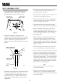
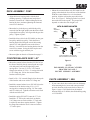
OPERATORS MANUAL MODEL GC-SSZ-48 MODEL GC-SSZ-6KH 1 2 3 21 5 3 1 2 3 6 2 9 10 11 4 12 3 13 7 12 2 11 2 14 2 23 3 12 11 15 16 12 8 2 2 17 2 3 1 03053COVER THIS MANUAL CONTAINS THE OPERATING INSTRUCTIONS AND SAFETY INFORMATION FOR YOUR SCAG ACCESSORY. READING THIS MANUAL CAN PROVIDE YOU WITH ASSISTANCE IN MAINTENANCE AND ADJUSTMENT PROCEDURES TO KEEP YOUR ACCESSORY PERFORMING TO MAXIMUM EFFICIENCY. THE SPECIFIC MODELS THAT THIS BOOK COVERS ARE CONTAINED ON THE INSIDE COVER. BEFORE OPERATING YOUR MACHINE, PLEASE READ ALL THE INFORMATION ENCLOSED. PART NUMBER 03064 WARNING FAILURE TO FOLLOW SAFE OPERATING PRACTICES MAY RESULT IN SERIOUS INJURY. * Keep all safety shields in place. * Before performing any maintenance or service, stop the machine and remove the spark plug wire. * If a mechanism becomes clogged, stop the engine before cleaning. * Keep hands, feet and clothing away from power-driven parts. * Read this manual completely as well as the Operator's Manual that came with your mower. * Keep others off the tractor (only one person at a time). REMEMBER - YOUR MOWER IS ONLY AS SAFE AS THE OPERATOR! Hazard control and accident prevention are dependent upon the awareness, concern, prudence, and proper training of the personnel involved in the operation, transport, maintenance, and storage of the equipment. This manual covers the operating instructions and illustrated parts list for: GC-SSZ-48 with a serial number of 4570001-4579999 GC-SSZ-6KH with a serial number of 4580001-4589999 Always use the entire serial number listed on the serial number tag when referring to this product. ® TABLE OF CONTENTS SUBJECT PAGE Introduction .................................................................................................. 1 General Safety Instructions .......................................................................... 1 Deck Assembly SSZ-48 .............................................................................. 1-3 Counter Balance Assembly SSZ-48 ............................................................ 3 Chute Assembly 6KH .................................................................................. 3-4 Frame Assembly 6KH .................................................................................. 4 Engine Mounting 6KH ................................................................................. 4-5 Bucket Support Assembly ........................................................................... 5-6 Illustrated Parts List ..................................................................................... 7-15 Limited Warranty Statement................................................................... Inside Back Cover MEMBER c WE SUPPORT OPE Equipment & Engine Training Council TECHNICIAN CERTIFICATION I INTRODUCTION • Before removing the grass bucket, disengage the mower cutter deck, stop the engine and wait for all movement to stop. This manual has been prepared to provide the information you need to correctly assemble, operate, and maintain this accessory. Read it carefully and keep it for future reference. Should you ever need repair parts or service, contact your Scag authorized parts and service dealer. • Always turn the engine off, remove the key and wait for all movement to stop before servicing, adjusting the mower deck, or cleaning the mower. To avoid personal injury, it is imperative that all safety instructions be observed. • Do not modify or alter any component of the grass catcher attachment. Any references made in this manual to the RH or LH side are determined with the operator in the normal operating position. • Do not allow anyone to ride on the grass catcher attachment or on the mower. The replacement of any part on this product by other than the manufacturer's authorized replacement part may adversely affect the performance, durability or safety of this product and will void the warranty. • Before removing any debris from the grass catcher components always turn off the engine, remove the key and wait for all movement to stop. • To reduce fire hazard, keep the engine free of grass, leaves, or excess lubricants. The manufacturer reserves the right to make changes or add improvements to its product at any time without prior notice or obligation. The manufacturer also reserves the right to decide, upon its discretion and at any time, to discontinue a product. • To improve engine life, keep it free of debris. ASSEMBLY INSTRUCTIONS SCAG POWER EQUIPMENT -NoteFor any instructions concerning an item number, refer to the illustrated parts breakdown on pages 7 thru 15. Use this illustrated parts list as a reference when following the assembly instructions. GENERAL SAFETY INSTRUCTIONS • READ THIS OPERATOR’S MANUAL and the operator’s manual that is supplied with the machine this accessory is used on. A replacement manual is available by contacting: Service Department Scag Power Equipment 1000 Metalcraft Drive Mayville, WI 53050 Please indicate the complete model and serial number of your Scag product when requesting replacement manuals. Remove all crating and lay out all hardware. Read all safety and operating instructions before assembly. DECK ASSEMBLY - SSZ- 48 • Remove the right side belt cover. • Using a 13/32" drill bit, drill the six (6) holes as indicated in Figure 1. Using an 11/32" drill bit, drill the remaining two (2) holes. • When operating the mower without the grass catcher attachment, the discharge chute extension must be installed in the normal, full down position. • Never operate your mower without the complete grass catcher and all guards and covers installed, or the discharge chute extension properly installed. 1 DECK ASSEMBLY CONT. • Mount the front tension bracket using two (2) 3/8 x 3/4" serrated flange hex head bolts and two (2) serrated flange nuts and tighten. • Loosen the right side spindle belt and remove the spindle pulley (refer to the Operator’s Manual included with your machine for instructions). Drill These 6 Holes To13/32" • Install the tension carriage bolt 3/8 x 2" and the 3/8" elastic nut. Do not tighten at this time. Drill These 2 Holes To 11/32" • Install the belt (P/N 48913) on the top pulley groove of the spindle to the gear box pulley. Tighten the tension bolt to proper belt tension. • Tighten the four (4) nuts on the gear box mount assembly which you had previously finger tightened. • Remove the RH anti-scalp wheels, front and rear. Locate and assemble the front and rear receiver brackets and bracket supports. Fasten with five (5) 5/16" serrated flange nuts and 5/16 x 3/4" flange bolts, finger tight. SC012GA Figure 1 • Mount the double pulley from grass catcher assembly carton to the right side spindle. The pulley should be flush with the top of the spindle shaft. See Figure 2. Remount the right spindle belt to the bottom slot in double pulley and tighten belt to proper tension. Mount hub flush with top of spindle shaft • Remount the front and rear anti-scalp wheels with the receiver bracket supports between the scalp wheel and the deck mount using 3/8 x 1" serrated flange bolts. Match the five (5) slots in the bracket support with those on the deck mount. Do not fully tighten at this time. • Mount the hinge bracket (P/N 421314) on the rear receiver assembly using the ring pin and hair pin. Nut • Insert the blower mounting bracket (P/N 45583) into the receiver brackets starting with the front receiver. Hold the rear of mounting bracket on a 45 degree angle. Insert the hair pin through the front arm hole of the blower mount bracket. Lower the back end of the mounting bracket into the rear receiver bracket making sure that the flat washers are on the outside of the bracket. Lock in place with the 3/8 x 4" hex head bolt and 3/8" elastic stop nut. Spacer Tapered Locking Hub Spindle Shaft -NoteThe retaining pin should be inserted from the left side of the bracket. SC007G Figure 2 • Mount the blower housing to the mounting bracket using three (3) 3/8" flat washers and elastic stop nuts. Do not tighten all the way because adjustments will need to be made. • Mount the reinforcement plate to the underside of the cutter deck using four (4) carriage bolts, 3/8 x 1-1/ 4". Mount the gear box support with the carriage bolts using four (4) 3/8" washers and four (4) 3/8" elastic stop nuts. Finger tighten so the box can be adjusted later. 2 • Mount the counter balance rod (P/N 44093) to the spring so that the hook faces the rear of the machine. With the counter balance lever in a horizontal position, slide the rod into the proper hole in the lever. See Figure 3. Pulling up on the lever, hook arm on the bolt in the top tab. The proper hole depends on where the deck height is set. DECK ASSEMBLY CONT. • Align the blower housing intake with the deck discharge opening. Tighten the anti-scalp wheel brackets, front and rear. While holding the blower housing in place, continue tightening the front and rear receiver brackets. WITH BLOWER MOUNTED • Mount the key in the keyway and slide the pulley removed from the right spindle onto the blower shaft so that the blower pulley will align with the gear box pulley. Tighten in place. Counter Balance Lever Deck Adjustment Setting • Install the blower drive belt (P/N 48914) on the gear box pulley and blower pulley. Push the blower housing back while lifting the rear of the housing upward 1/2" and tighten the nuts on the blower housing. Lower the blower housing bracket into the rear receiver mount. Swing the latch in place and secure with the ring pin and hair pin. If deck is adjusted in the third hole, lever rod should be in the fourth hole. WITHOUT BLOWER MOUNTED Counter Balance Lever Deck Adjustment Setting SC006GA • Mount weights on chassis as illustrated on page 13. If deck is adjusted in the third hole, lever rod should be in the third hole. COUNTER BALANCE ASSY. / 48" Figure 3 • Mount the counter balance bracket (P/N 421345) to the front of the kick plate by removing the two right side dash panel bolts and far right hinge panel carriage bolt. Use two (2) 5/16 x 3/4" serrated flange bolts and one (1) 5/16 x 1" carriage bolt with a 5/16" flange nut. Secure the counter balance bracket to the kick plate. -NOTEFOR MODEL GC-SSZ-48 CATCHER PROCEED TO PAGE 5 BUCKET SUPPORT ASSEMBLY • Install a 3/8 x 3/4" serrated flange bolt in the top tab of the bracket and secure with a 3/8" flange nut. CHUTE ASSEMBLY / 6KH • Install the counter balance lever (P/N 421346) to the bottom tab of the bracket using a 3/8 x 1-1/2" carriage bolt, compression spring, 3/8" flat washer and 3/8" elastic nut. Tighten so that the nut is flush with the end of the bolt. 1. If your cutter deck does not have the two discharge chute mounting holes, locate and center punch the two hole locations in the cutter deck as shown in Figure 4, page 4. Drill the holes at the marked locations using a 1/8" drill bit, then finish drilling using a 13/32" drill bit. • Install the spring (P/N 48755) onto the “U” bolt. Install the “U” bolt to the cutter deck so that the 5/16" flange nuts are flush with the “U” bolt ends. Lock the top nuts down against the deck. Tighten the flange nuts under the deck 1/4 turn to lock the “U” bolt in place. 3 FRAME ASSY. CONT. • Mount the rear tube of the frame using four (4) 3/816 x 2.5" hex head bolts (A), elastic stop nuts (B), along with two (2) rear tube clamps (E). 9" 4.25" • Mount the lower brace tube using three (3) 3/8-16 x 2.5" hex head bolts (A), flat washers (C), and elastic stop nuts (B). • While holding the engine mounting frame in place, tighten all the previously mounted hardware. 0305412698 3/4" A = 3/8-16 x 2.5" Hex Head Bolt B = 3/8-16 Elastic Stop Nut C = 3/8 Flat Washer D = Front Tube Clamp E = Rear Tube Clamp F = 5/16-18 Elastic Stop Nut G = 5/16-18 x 1-3/4" Hex Head Bolt A E B G Engine Guard Weldment Figure 4, Hole Location A 2. Install the boot mounting support tabs (items 39 & 40) to the cutter deck, using (1) 5/16-18 x 1" bolt, (1) 5/16-18 x 1-1/4" bolt and (2) 5/16-18 elastic stop nuts. Do not tighten the bolts at this time. C B B Engine Mounting Frame C F A Lower Brace Tube 3. Install the boot mounting bracket (item 37) to the boot (item 7) in the holes toward the front of the boot, using (2) 3/8-16 x 1" bolts, (2) 3/8" flat washers and (2) 3/8-16 elastic stop nuts. F D C B A A -NoteIf you are installing the catcher to a machine with a 52" cutter deck, you must install the filler plate (item 25) to the boot. SC003GA Figure 5 ENGINE MOUNTING / 6KH • For SSZ machines with a Kohler engine, remove the exhaust pipe (P/N 48964) and install the new exhaust pipe (P/N 481002) that came with your grass catcher. Use the "U" clamp (P/N 48633) that came with the grass catcher to fasten the new exhaust pipe to the muffler. 4. Install the filler plate (item 25) to the boot (52" models only) in the rearward holes in the boot using (2) 5/16-18 x 3/4" bolts, (2) 5/16" flat washers and (2) 5/16-18 elastic stop nuts. FRAME ASSEMBLY / 6KH • Mount the engine and the engine guard weldment to the engine mounting frame using four (4) 5/16-18 x 1-3/4" hex head bolts (G), and elastic stop nuts (F). See Figure 6, Page 5 for the correct mounting holes for the cutter deck used on the machine. • Install the engine mounting frame (P/N 45561) to the tractor. See Figure 5, page 4. • With the frame in place on the rear of the chassis, mount the front tube of the frame using two (2) 3/816 x 2.5" hex head bolts (A), flat washers (C), elastic stop nuts (B), and front tube clamp (D). Do not tighten fully until the remainder of the mounting hardware is in place. 4 ENGINE MOUNTING / 6KH CONT. -NoteTo prevent the discharge boot from becoming plugged, the cutter blades should not be engaged without the blower engine running. A = SSZ-52 Engine Mount Holes B = SSZ-61 Engine Mount Holes B A B A B A A When cleaning out the boot, always disengage the cutter blades and shut off the mower engine. B SC014G Figure 6 • Mount the rear blower housing assembly using four (4) 5/16-24 x 1" fine thread bolts and four (4) 5/16" lockwashers. Install into tapped engine holes. BUCKET SUPPORT ASSEMBLY • Using two “J” hooks, 5/16 x 3/4" carriage bolts, and 5/16" serrated flange nuts, fasten the bottom tray to rear of the frame. With the remaining two "J" hooks, hardware and the two "L" brackets, finish mounting the tray to the side of the frame. The "L" brackets should be mounted on the underside of the "J" hooks as shown in Figure 7. See the Bucket Support Components pages in the illustrated parts section of this manual for added visual aid. • Install the fan assembly with key and secure onto the crankshaft with a 3/8-24 x 2" fine thread bolt and 3/8" lockwasher. • Using a rubber mallet, tap, then tighten the blower fan hub onto the crankshaft. Rotate the fan to be sure the fan does not hit the housing. • Install the 8" inlet hose onto the boot and inlet adapter using two hose clamps. Debris Guard • Mount the blower inlet adapter to the blower housing using six (6) 5/16-18 serrated flange nuts. Tray • Install the exhaust deflector (P/N 481697) to the machine’s muffler to adequately direct exhaust gases away from the grass catcher engine mounting frame. "L" Bracket "J" Bracket • Fill the engine with approximately 1/2 quart of oil (See the engine operator's manual that came with your grass catcher). Fill the fuel tank with fresh gasoline that has a minimum octaine rating of 87. ! SC015 Figure 7 • Mount the side support brackets using four (4) 5/1618 x 3/4" carriage bolts and flange nuts for the bottom mounting. Use the second hole from the top on the support frame to mount the slotted hole in support mount tray. Fasten with two (2) 5/16-18 serrated flange nuts. WARNING: Be safe when adding fuel. Add fuel in a well ventilated area. Wipe any spills before attempting to start the engine. Connect all tubes before starting the engine or engaging the PTO switch. • Install the debris guard to the tray lip, "L" brackets, and debris guard mount using nine (9) 5/16-18 x 1/ 2" carriage bolts and 5/16-18 serrated flange nuts. Be sure the guard is mounted to the back side of the tray lip and the backside of the debris guard mount. See illustration 6 for fastening the "L" brackets. 5 • Install the left and right brace hinge plates to the hopper cover using four (4) 3/8-16 x 1" capscrews, flat washers, and elastic stop nuts. Tighten within 1/2 turn of being tight. • Mount the hopper onto the tray bracket so it rests against the support frame. Put the lid on top of the hopper and center from side to side. Locate the two (2) hex head hinge bolts (3/8-16 x 1-1/2"), twelve (12) spacer washers and two (2) elastic stop nuts. • Insert as many spacer washers as needed to take up the space between the hinge plate and support frame tubes so that the lid remains centered. Tighten the elastic stop nuts until snug, then back off 1/8 of a turn so that the lid can pivot easily. • Tighten the four (4) hinge plate bolts on the lid, starting on right side. • Install the cover support rod by mounting the two hair pins to inside holes in the rod. Slide the 2" flat washer onto the bottom of the rod. Insert the support rod into the hole on the right hinge plate and into the lower hole on the arm of the support bracket. Slide a 3/8" flat washer onto the rod in the lower hole and insert a hair pin. Holding the support rod in place, raise the lid and lock it open. Insert a hair pin in the lid bracket. • Insert the elbow in the lid and lock in place. Mount the hose and hose clamp on to the elbow. • Recheck all hardware and fittings for propertightness. Test run to verify that the grass catcher operates properly. 6 DECK/COUNTER BALANCE COMPONENTS GC-SSZ-48 1 25 2 6 4 10 9 16 1 25 12 7 3 4 15 4 13 5 20 14 19 11 27 8 17 28 29 18 7 2 26 24 4 17 22 18 23 21 REF. CUTTER DECK 7 SC000GB Ref. Part No. Number Description Ref. Part No. Number Description 1 2 3 4 5 6 7 8 9 10 11 12 13 14 15 16 17 18 19 20 21 22 23 24 25 26 27 28 29 04021-10 48915 421319 04003-12 45565 04063-06 04019-03 46627 48136-01 48135-07 48236 45583 04001-30 04062-01 421484 04067-04 Nut, Elastic Stop 5/16-18 Bearing Assembly Cover, Blower Housing Carriage Bolt, 5/16-18 x .75 Fan Weldment Key, .25 x .25 x 1.50 Nut, Serr. Flange 5/16-18 Blower Housing Weldment w/Decals Clamp, Hose Hose, 6" x 48" Decal, Danger Blower Mounting Weldment Bolt, Hex Head 3/8-16 x 4" Hair Pin, .094 dia. x 1.62 Latch Ring Pin 04021-09 04017-27 421312 421483 421495 45582 04062-03 04041-07 04040-04 46625 48924 48141 04001-01 Nut, Elastic Stop 3/8-16 Capscrew, Serr. Flange 3/8-16 x 1 Mounting Bracket, Rear Latch Plate Mounting Bracket, Front Mounting Weldment, Front Hair Pin, .148 dia. x 2.75 Flat Washer, 3/8 (.391 x .938 x .105) Flat Washer, 5/16 (.344 x .688 x .065) Blower Housing Assembly Pulley, 5.75 O.D. Tapered Hub, 1.00 Bore Bolt, Hex Head .25-20 x .75 * Common hardware which should be purchased locally. All bolts grade 5 plated, all other fasteners zinc plated. 7 GC-SSZ-48 DECK/COUNTER BALANCE COMPONENTS (48) 30 5 6 35 17 18 15 1 16 2 14 33 25 3 36 34 15 19 23 7 8 9 13 4 9 22 29A 10 1 20 29 12 7 11 32 31 17 21 10 8 7 24 18 25 28 3 32 2 1 25 37 26 27 16 SC001GB 8 DECK/COUNTER BALANCE COMPONENTS GC-SSZ-48 (48) Ref. No. Part Number Description 1 2 3 4 5 6 7 8 9 10 11 12 13 14 15 16 17 18 19 20 21 22 23 24 25 26 27 28 29 29A 30 31 32 33 34 35 36 37 04001-01 48248 48924 04017-28 46757 04029-03 04021-09 04041-07 04003-03 04063-07 48919 04100-01 48755 44093 421346 04017-26 04019-04 48215 04062-01 421345 48050 04003-04 04017-16 48923 04019-03 421325 04003-11 421324 45615 45616 481040 48141 48913 48914 04017-04 421618 04019-02 46716 Bolt, Hex Head 1/4-20 x .75 Tapered Hub, .875 Bore Pulley, Tapered Bore 5.75 O. D. Capscrew, Serr. Flange 3/8-16 x 1.25 Belt Cover, w/Decal Wingnut, Plastic 3/8-16 x .875 Nut, Elastic Stop 3/8-16 Flat Washer, 3/8 (.375 x 2.00 x .060) Carriage Bolt, 3/8-16 x 2.00 Key, Woodruff #9 3/16 x .75 Gear Box, 90 Degree Drive U-Bolt, 5/16-18 x 2.19 Spring,Counter Balance Rod, Counter Balance Lever, Counter Balance Capscrew, Serr. Flange 3/8-16 x .75 Nut, Serr. Flange 3/8-16 Grip, Shift Lever Hair Pin, .094 x 1.62 Mounting Bracket, Counter Balance Spring, Compression Carriage Bolt, 5/16-18 x 1.00 Capscrew, 5/16-18 x .75 Pulley, Double Groove 5.75 O. D. Nut, Serr. Flange 5/16-18 Reinforcement Plate, Gear Box Carriage Bolt, 3/8-16 x 1.25 Anchor Bracket, Tension Bolt Support Weldment, Gearbox-upper Support Weldment, Gearbox-lower Decal, Warning Tapered Hub, 1.00 Bore Belt, Gearbox Drive Belt, Blower Drive Capscrew, 1/4-20 x .50 Serr. Flange Skirt, Belt Cover Nut, 1/4-20 Serr. Flange Gearbox Assembly * Common hardware which should be purchased locally. All bolts grade 5 plated, all other fasteners zinc plated. 9 BUCKET SUPPORT COMPONENTS (UPPER) 6 7 9 5 8 4 3 2 1 10 20 13 A 11 14 12 17 16 15 18 A 19 10 SC002GB 10 BUCKET SUPPORT COMPONENTS (UPPER) Ref. Part No. Number 1 2 3 4 5 6 7 8 9 10 11 12 13 14 15 16 17 18 19 20 Description 48135-07 48135-08 48136-01 48909 46512 48928 421348 * 421300 04003-12 48137-03 04021-10 481017-01 421446 421421 04017-26 04041-20 421418 421947 46841 421949 Hose, 6" x 48" (Model SSZ With A 48" Deck) Hose, 6" x 24" (Model SSZ With A 52, 61" Deck) Clamp, Hose Elbow, Grass Catcher Cover Assembly, Grass Catcher (Includes Items 5,6, 7,12, 13 & 16) Deflector, Grass Catcher Backing Plate, Deflector Rivet, 3/16 X .625" Handle Bolt, 5/16-18 x .75" Carriage Strap, Rubber Nut, 5/16-18 Elastic Stop Seal Rubber Screen Hinge, Left Hand Capscrew, 5/16-18 x .75" Serrated Flange Washer, Pop Rivet Plate, Hinge Backing Stiffener, Grass Catcher Hopper Hopper Assy., Grass Catcher With Decal (Incl. 421947) Backing Plate, Handle * Common hardware which should be purchased locally. All bolts grade 5 plated, all other fasteners zinc plated. 11 BUCKET SUPPORT COMPONENTS (LOWER) 1 2 3 21 5 3 1 2 3 6 2 9 10 11 4 12 3 13 7 12 2 11 2 14 2 23 3 12 11 15 16 12 8 2 2 17 3 2 1 12 SC015G WEIGHT KITS (48, 52/61) 48 18 18 52/61 11 11 20 19 19 11 11 14 14 SC003GB BUCKET SUPPORT COMPONENTS (LOWER) AND WEIGHT KIT Ref. Part No. Number Description 1 2 3 4 5 6 7 8 9 10 11 12 13 14 15 16 17 18 18 19 20 21 Brace Nut, 5/16-18 Serrated Flange Bolt, 5/16-18 x .75" Carriage Tray Mount Guard Debris Guard W / Decal Bracket, Lower Clamp, Tray Rod, Cover Support Bolt, 3/8-16 x 1.50" Flat Washer, 3/8 (.391 x .938 x .105) Hair Pin, .080 x 1.19 Hinge, Right Hand Nut, 3/8-16 Elastic Stop Flat Washer, 3/8 (.375 x 2.00 x .060) Bolt, 5/16-18 x 1.00" Support Frame Weldment Bolt, 3/8-16 x 6.00" Hex Head (Model SSZ With A 48" Deck) Bolt, 3/8-16 x 5.00" Hex Head (Model SSZ With A 52", 61" Deck) Weight Bar Mounting Bracket, Weight Bar (Model SSZ With A 52", 61" Deck) Decal, Hot Engine 421309 04019-03 04003-12 421432 421951 46845 421962 421308 44089 04001-20 04041-07 04062-02 421422 04021-09 04041-10 04003-04 45552 04001-100 04001-47 42956 421444 481289 * Common hardware which should be purchased locally. All bolts grade 5 plated, all other fasteners zinc plated. 13 ENGINE SUPPORT COMPONENTS GC-SSZ-6KH 4 33 32 2 3 15 9 12 1 13 10 11 2 16 21 34 14 1 18 20 26 27 30 27 28 24 26 17 27 28 28 22 19 27 23 26 29 23 31 27 28 36 26 25 40 22 39 26 23 23 41 28 39 5 35 42 37 6 5 27 7 8 14 GCSSZ99ESC ENGINE SUPPORT COMPONENTS GC-SSZ-6KH Ref. No. Part Number Description 1 2 3 4 5 6 7 8 9 10 11 12 13 14 15 16 17 18 19 20 21 22 23 24 25 26 27 28 29 30 31 32 33 34 35 36 37 38 39 40 41 42 481564 45080 48136-01 48135-08 48136-02 48135-02 481734 04001-20 45077 45081 04002-02 04063-06 04001-88 04030-05 04001-56 04030-03 48633 45374 45561 04001-92 04001-12 04040-15 04021-10 481002 422591 04001-31 04041-07 04021-09 421440 421443 421442 481697 481698 04040-11 04062-02 04001-38 422588 04001-10 422590 422589 04001-09 44131 Engine, Kohler 6 hp Blower Housing Weldment Clamp, Hose 6" Hose, 6" x 24" Clamp, Hose 8" Hose, 8" x 29" Boot Bolt, Hex Head,3/8-16 x 1-1/2" Fan Weldment Blower Inlet Adapter Wingnut, Elastic Stop,5/16-18" Key, .25 x .25 x 1.50" Bolt, Hex Head 7/16-20 x 2.00" Lockwasher, 7/16 Bolt, Hex Head 5/16-24 x 1.0" Lockwasher, 5/16 Clamp, Muffler Engine Guard Weldment Engine Mounting Frame Bolt, Hex Head 5/16-18 x 3-1/4" Bolt, Hex Head 5/16-18 x 1-3/4" Flat Washer, 5/16 (.375 x .875 x .083) Nut, Elastic Stop, 5/16-18 Tube, Exaust Filler Plate, Chute-52" Deck Only Bolt, Hex Head, 3/8-16 x 2-1/2" Flat Washer, 3/8 (.391 x .875 x .088) Nut, Elastic Stop, 3/8-16 Tube, Lower Brace Clamp, Rear Tube Clamp, Front Tube Ehaust Deflector Screw, Kohler Special Flatwasher, 7/16 Hair Pin Cotter, .080 x 1.19 Bolt, Hex Head, 5/16-18 x 3/4" Mounting Bracket, Chute Bolt, Hex Head, 5/16-18 x 1-1/4" Mounting Tab, Chute Support, Chute Mounting Bolt, Hex Head, 5/16-18 x 1" Latch Pin, Chute * Common hardware should be purchased locally. All bolts grade 5 plated, all other fasteners zinc plated. 15 LIMITED WARRANTY- COMMERCIAL A CCESSOR Y ACCESSOR CCESSORY Any part of the Scag commercial accessory manufactured by Scag and found, in the reasonable judgment of Scag, to be defective in material or workmanship, will be repaired or replaced by an Authorized Scag Service Dealer without charge for parts and labor. The Scag accessory, including any defective part, must be returned to an Authorized Scag Service Dealer within the warranty period. The expense of delivering the accessory to the dealer for warranty work and the expense of returning it back to the owner after repair or replacement will be paid for by the owner. Scag’s responsibility in respect to claims is limited to making the required repairs or replacements, and no claim of breach of warranty shall be cause for cancellation or rescission of the contract of sale of any Scag machine. Proof of purchase will be required by the dealer to substantiate any warranty claim. All warranty work must be performed by an Authorized Scag Service Dealer. This warranty is limited to 90 days from the date of original retail purchase for any Scag accessory that is used for commercial purposes, or any other income-producing purpose including rental use. This warranty does not cover any accessory that has been subject to misuse, neglect, negligence, or accident, or that has been operated in any way contrary to the operating instructions as specified in the Operator's Manual. The warranty does not apply to any damage to the accessory that is the result of improper maintenance, or to any accessory or parts that have not been assembled or installed as specified in the Operator's Manual. The warranty does not cover any accessory that has been altered or modified. In addition, the warranty does not extend to repairs made necessary by normal wear, or by the use of parts or accessories which, in the reasonable judgment of Scag, are either incompatible with the Scag mower or adversely affect its operation, performance or durability. This warranty does not cover engines and electric starters, which are warranted separately by their manufacturer. Scag Power Equipment reserves the right to change or improve the design of any accessory without assuming any obligation to modify any accessory previously manufactured. All other implied warranties are limited in duration to the 90 day warranty period. Accordingly, any such implied warranties including merchantability, fitness for a particular purpose, or otherwise, are disclaimed in their entirety after the expiration of the appropriate ninety day warranty period. Scag’s obligation under this warranty is strictly and exclusively limited to the repair or replacement of defective parts and Scag does not assume or authorize anyone to assume for them any other obligation. Some states do not allow limitations on how long an implied warranty lasts, so the above limitation may not apply to you. Scag assumes no responsibility for incidental, consequential or other damages including, but not limited to, expense for gasoline, oil, expense of delivering the machine to an Authorized Scag Service Dealer and expense of returning it back to the owner, mechanic’s travel time, telephone or telegram charges, rental of a like product during the time warranty repairs are being performed, travel, loss or damage to personal property, loss of revenue, loss of use of the mower, loss of time, or inconvenience. Some states do not allow the exclusion or limitation of incidental or consequential damages, so the above limitation or exclusion may not apply to you. This warranty gives you specific legal rights, and you may also have other rights which vary from state to state. © 1998 SCAG POWER EQUIPMENT DIVISION OF METALCRAFT OF MAYVILLE, INC PART NO. 03064 PRINTED 6/98 PRINTED IN USA