1
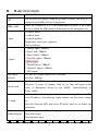
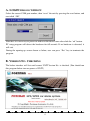
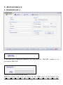
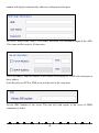
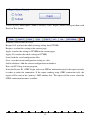
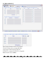
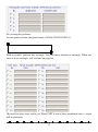
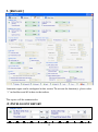
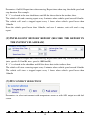
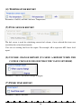
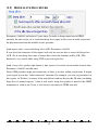
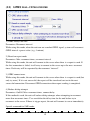
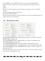
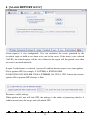
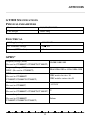
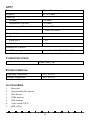
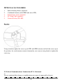
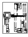
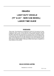
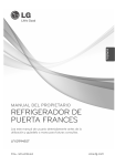
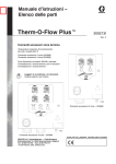
GPS&GPRS TRACKING SYSTEM
MODULE: GT3000 SERIES
User Manual
I.
INTRODUCTION
GPS GPRS tracking system GT3000 utilize the GPS tracking function and car alarm
functions in one unit. You can monitor the vehicle location and control the car alarm
remotely. In addition, the unit will send event report if any trigger occurs. It has built-in 8
outputs and 5 inputs to perform essential alarm functions.
1.1 REPORT STRUCTURE
The standard report sent by the unit includes the information: (1) unit’s ID, (2) status, (3)
time, (4) GPS’s latitude and longitude, (5) speed, (6) direction, (7) temperature, (8) device’s
status, (9) event number, and (10) report configuration parameters.
(1)
Unit’s ID: each device has its own unique ID and must be registered in the server in
order to perform monitoring or controlling.
(2)
(3)
Status: A=Valid, L=Last known
Time: report time in Greenwich Mean time zone.
(4)
(5)
(6)
GPS’s latitude and longitude.
Speed: in km/H
Direction: in degree to the North.
(7)
Temperature: in Celsius. If the temperature is not connected, ‘NA’ will be shown in
this field.
(8)
Device’s status: there are 32 states to represent the I/O and working modes for the
both the device and the build in alarm.
(9)
Event number: all the generated reports will include a unique event number to
indicate why it has been sent.
(10) Report configuration parameters: user can remotely change the report configuration,
and the configuration parameters will be shown in this field.
1.2 REPORT SETUP
GT3000 must be initialized by PC setup program in order to make communication with the
remote server /call center. There are four main sections that allow users to program the
1
device, (1) User detail (Device ID, server IP, and port, SMS number, GPRS APN…) (2)
In-built Geo-fence definition (up to 5 circular, 5 rectangular and 20 point Geo-fence shapes
can be set in the device) (3) Report setting (Time, Distance, Intelligent mode, Temperature,
Low battery, Course change…) (4) ALARM report (to enable or disable the event
generated by the inputs, e.g. ignition, DOOR). Those data will have been saved in device’s
EEPROM and will not be lost even if the power is failure.
Note that the device ID, GPRS APN name, GPRS login name and password need to be set
in initial PC setup in order to make the connection to the server. All the reports
configuration or Geo-fence setup can be changed at anytime via over the air commands.
The automatic reporting mode can be categorized as ‘time’ report, ‘distance’ report, or
‘time & velocity’ report. User can choose the reporting mode and related parameters via the
PC setup program or the remote sever.
The event trigger report is also configurable. User can turn on or off any event-generated
report from the PC setup program or via the air command. The event-triggered report
include (1) In-vehicle Door close/open (2) In-vehicle ignition on/off (3) Temperature range
in/out the preset range.
The server cannot only configure the device just like the PC setup program does, but it also
can send the command to control the device. The server can control both the device and the
build in alarm.
1.3 GEO-FENCE FUNCTION
The device has built-in 30 Geo-fence sets (1 immediate Geo-fence, 4 circular, 5 rectangular
and 20 point); it will send the report to the server if the Geo-fence event is triggered. User
can setup the Geo-fence area from the PC setup program or sending the defined.
A unique immediate Geo-fence function:
‘Immediate-Geo-fence function’ is a circular type Geo-fence that can be activated or
deactivated from a single button. When activated, the system will record the current
position and use the pre-defined radius as a circular Geo-fence to guard the vehicle. If the
vehicle moves out of the preset Geo-fence zone, a report will be generated to the server.
User can deactivate the self-Geo-fence at any time by pressing the valet switch again. If the
2
GPS cannot be located when the Immediate Geo-fence function is been executed, GT3000
will use the last known position as the origin of the circular Geo-fence zone to perform the
protection.
US Patten for immediate Geo-fence function is pending.
1.4 STORE AND FORWARD ABILITY
When there is no GPRS service or the server close. The unit will send short message to the
server if defined SMS number. All the stored report will be forward to the server when
GPRS connection is completed next time.
1.5 TCP AND UDP SOCKET SUPPORT
GT3000 supports both UDP and TCP socket communication. The server IP, port number
and socket type can be selected from the PC-setup program or remote server command. In
addition, the connection can be swap over to any server IP or port (either UDP or TCP) via
the air command.
1.6 THE SERVER CAN SEND THE COMMAND TO CONTROL THE
DEVICE AND THE BUILD IN ALARM.
Command for in-vehicle control:
We design 8 commands that can be integrated into the server, so that the users can control
their vehicles. Those commands are: (1) Door lock, (2) Door unlock, (3) Arming, (4) Panic,
(5) Enable anti-car jacking, (6) Emergency release, (7) Trunk release, (8) Channel 2
outputs.
NOTES:
1.
2.
Arming (this command is valid only if when ignition is off): If ignition Off,
Server send arming command. The door will lock and the Engine will be Disable
starter (if the starter cut relay connected), after the unit received the command.
Panic: (can be performed at any time) If Server send panic command, the horn
will sound and parking lights will flash for 30 seconds after the unit received the
command.
3
3.
Enable anti-car jacking: (can be performed at any time) If Server sends anti-car
jacking command, the system will enter anti-carjacking mode after the unit
received the command. When the anti-carjacking has activated, from the
beginning to 30 seconds, the parking light will flash once and horn chirp once
interval 10 seconds, from 31 to 60 seconds, the parking light will flash once and
horn chirp once interval 5 seconds, from 61 to 120 seconds, the parking light will
flash once and horn chirp once interval 1 seconds, after 120 seconds, system will
locked ignition and parking light will flash once and horn will chirp once interval
1 seconds. To release anti carjacking: To send emergency commands or ignition
ON, press emergency button to release anti carjacking.
4.
Emergency release: (can be performed at any time) If Server send Emergency
release command while at Arming mode, panic mode, anti-car jacking mode.
Then system will exit ‘Arming’, ‘Anti-carjacking’, ‘Panic’ mode. The ‘Arming’,
‘parking light’ and ‘horn’ outputs will back to normal (Disarm) status.
1.7 VALET SWITCH OPERATION
User can use the supplied Valet switch to perform 5 essential tasks, including (1) sending
help report (2) activate or deactivate Immediate Geo-fence (3) Panic (4) sending ‘Duty on’
or ‘Duty off’ report to the server (5) Emergency release to exit ‘ARM’, ‘Anti-carjacking’ or
‘Panic’ modes
(1) Sending ‘HELP’ report
Press the button once, The LED will flash once and a ‘HELP’ report will be generated.
(2) Activate or deactivate Immediate Geo-fence
Press the button and release it when the LED flashes once. After releasing it, the LED will
stay continuously on to indicate the ‘Immediate Geo-fence’ is on. To deactivate: Press the
button (the LED will be temporally off), and release it when the LED flashes once. After
releasing it, the LED will then stay continuously off. A report will be sent out if the vehicle
goes out/in to the Geo-fence zone.
(3) Panic
Press the button (the LED will be temporally stay off) and release it when the LED flashes
4
twice. After releasing it, a panic action will be generated.
(4) ‘Duty on’ or ‘Duty off’ reports / ‘Status on’ Status off’ reports
Press the button (the LED will be temporally stay off) and release it when the LED flashes
3 times. After releasing it, a ‘Duty on’ report will be sent out. To deactivate: Press the
button (the LED will be temporally stay off) and release it when the LED flashes 3 times.
After releasing it, a ‘Duty off’ report will be sent out.
(5) Emergency release to exit ‘ARM’, ‘Anti-carjacking’ modes.
ignition ON, press and hold the button (the LED will be temporally stay off) and release it
when the LED flashes 5 times. After releasing it, ‘ARM’, ‘parking light’, and ‘horn’ outputs
will back to normal (Disarm) status.
1.8 HISTORY REPORT
Flash memory for recording reports up to 3000 reports. It can be read out from the PC setup
program via serial port.
1.9 BACKUP BATTERY (OPTIONAL)
The system has a built-in rechargeable battery for emergency use. The system will send a
power cut report when all the external power is disconnected.
1.10 LED INDICATION
Three LED indicate the status of the POWER, GPRS signal and GPS signal.
1.11 KEEP ALIVE PROCEDURE
Keep alive procedure (in order keep connection in GPRS network, the unit can be set to
send short keep alive report to the server in order to prevent the disconnection from the
mobile service provider)
5
II.
BASIC FUNCTIONS
FUNCTIONS
GPS
GPRS, SMS
APPLICATIONS
GPS receiver will output a complete position, velocity, and time (PVT)
solution in the NMEA Version 3.0 protocol
GPRS use standard TCP or UDP communicate protocol. If the GPRS
service is failed, the SMS mode will be turned on for emergency use.
In-vehicle Door+
5 input
In-vehicle DoorIn-vehicle ignition
Temperature sensor port (optional)
Valet switch port
1. Parking light (-300mA)
2. Door Lock (-300mA)
3. Door Unlock (-300mA)
8 output
GPS output
interface
4. Start kill output (-300mA)
5. Horn output
6. Trunk Release (-300mA)
7. Channel 2 output (-300mA)
8. GPS output
GPS port will output NMEA 0183 GPS data.
Data rate: 4800 bps
(1) Sending HELP report (2) activate or deactivate Immediate
Valet Switch
Geo-fence (3) panic (4) sending ‘Duty on’ or ‘Duty off’ report to the
server (5) Emergency release to exit ‘ARM’, ‘Anti-carjacking’ or
‘Panic’ modes
Initialize the unit and program the device, including Network APN,
PC-setup
Standard Report
server IP address, user message, report control, and Geo-fence setting,
etc …
Note that Network APN and server IP details must be set before the
installation.
Automatic report for AVL tracking purpose:
Fixed time report
Fixed distance report
6
Intelligent report (combine time and distance)
Keep alive report
Temperature report
Speeding report
Event Report
Low battery report
Geo-fence trigger report
ALARM trigger report, e.g. PANIC mode, ARM, ignition inputs, etc …
History data store 3000 report can be saved in unit, and read from server and pc-setup
III.
STATUS INDICATOR
SYSTEM LED:
RED: Power indicator. When the
unit power on, the led will light all the time. When
power cut off the unit works with backup battery, the led will flash until all the report is
sent to server.
YELLOW: GSM/GPRS indicator. Yellow LED will flash when the device is connected
to the server with valid GPRS connection. It will stay continuously on when it is in GSM
mode. It will stay off if there is no GSM reception.
GREEN: GPS indicator. This LED will be ON when the unit received a valid GPS data.
Note that the YELLOW and Green LEDs indication will not be valid until the system goes
to the working mode, normally 30 seconds after power on.
IV.
PC SETUP AND SYSTEM INITIATION
PC setup Procedure:
(1.) Connect the 4 pin USB cable to the DB9 port.
(2.) Open the PC setup program.
(3.) Select the correct COM port for communication.
(4.) Power on the device or press the reset button for at least 2 second.
(5.) Click “ok” to start the program
Note that, if the connection fails, please check the cable connection is secured correctly.
Press the reset button for a longer time, e.g. another 3 seconds.
7
A. LOGIN DIALOG WINDOW
Select the correct COM port number, then “reset” the unit by pressing the reset button, and
next click “OK”.
Note that: it is necessary to power on and reset the device soon after click the “ok” button.
PC setup program will detect the hardware for 60 seconds. If no hardware is detected, it
will exit.
During the opening up screen shown as below, user can press “Esc” key to terminate the
program.
B. VERSION NO. CHECKING
The below interface will last until correct UNIT Version No. is checked. (You should run
this program before turn on power of UNIT)
8
C. MAIN INTERFACE
1. [USER DETAIL:]
If the SIM card is password protected, user can input the “SIM PIN” window to set
password of SIM Card.
Device ID: Set UNIT ID for the device.
IMEI: Any operate with ‘request or request all’ after GPRS power on, the module series
9
number will display automatically, otherwise it displayed with space.
Set Access Point Name (APN), User Name, Password. The maximum length of the APN,
User name and Password is 49 characters.
TCP/UDP address and Port number of the remote server being set, UNIT will send report to
these address.
Note that only one TCP or UDP server will be used at the same time.
Set the SMS Number of the server. The unit will send reports to the server if GPRS
connection is failed.
10
UNIT can save 3000 reports (3000-1) recently; Click ‘Export’ button can export them with
Excel or Text format.
Initialize: clear all data in UNIT.
Request All: read out the whole existing setting from GT3000.
Request: read out the setting in the current page.
Apply: transfer the setting to GT3000 in the current pages.
Apply All: transfer the whole setting to GT3000.
Load: load the saved configuration files.
Save: save the current configuration setting to a file.
Add to database: Add the current configuration to database
Exit: exit PC-Setup to main program.
Note that Device ID, GPRS Login and server IP/Port information need to be input correctly
in order to make the connection. If the report sending using GPRS connection fails, the
report will be sent to the ‘primary’ SMS number first. The report will be resent, when the
GPRS connection becomes available.
11
2. [GEO-FENCE:]
Four Circular Geofence and one self-geofence:
Circular Geofence must set origin and radius:
Origin format :N2446.5321E12120.4231;
N2446.5321 is latitude, E12120.4231 is longitude.
Radius from 0.1 km to 1000km.
12
Five rectangular geofence:
Set two points position, the point format is N2446.5321E12120.4231;
With two points, generate one rectangle. Unit will detect whether in rectangle. When unit
enter or leave rectangle, will send one message out.
20 point Geo-fence areas can be set. When UNIT is out of these predefined zones, a report
will be generated.
13
3. [REPORT:]
Automatic report can be configured in this section. To activate the function(s), please select
“√” in checkbox and fill in data in the textbox.
The reports will be summarized as
(1) INTELLIGENT REPORT
14
Parameters: On/Off, Report time when moving, Report time when stop, threshold speed and
stop duration. For example:
If “√” is selected in the two checkboxes and fill the above data in the textbox, then:
The vehicle will send a moving report every 5 minutes when vehicle speed exceed 18km/hr
The vehicle will send a stopped report every 1 hours when vehicle speed lower than
18km/hr
Even the vehicle speed lower than 18km/hr, and over 5 minutes, unit will send a stop
report.
(2) INTELLIGENT HISTORY REPORT (RECORD THE REPORT IN
THE SYSTEM’S FLASH RAM)
Parameters: On/Off, Report time when moving, Report time when stop, and threshold speed.
(min. speed is 0.1 km/Hr, max. speed is 1000 km/Hr).
If “√” is selected in the checkbox and fill the above data in the textbox, then:
The vehicle will store a moving report every 5 minutes when vehicle speed exceed 18km/hr
The vehicle will store a stopped report every 1 hours when vehicle speed lower than
18km/hr
(3) IO CONNECT SELECTION
Parameters: to select unit connect with temperature sensor or with AD1 output or with fuel
sensor
15
(4) TEMPERATURE REPORT
Parameters: On/Off, and min. and max. Temperature.
(5) FUEL SENSOR REPORT
The fuel sensor is used for calculating current fuel volume, if user selected this item, user
can define the value discretionarily.
User can set warning fuel level for report. For example, 60 to represent 60% lower level
report.
(6) COURSE CHANGE REPORT (TO SEND A REPORT WHEN THE
COURSE CHANGE IS BIGGER THAN THE VALUE SET HERE)
Parameters: On/Off, and course change in degree.
(7) FIXED TIME REPORT
Parameters: On/Off, and time.
16
(8) FIXED DISTANCE REPORT
Parameters: On/Off, and distance. (Min. distance is 0.1 km, max. distance is 100 km).
(9) SPEEDING REPORT: (MIN. SPEED IS 0.1 KM/HR, MAX. SPEED
IS 1000 KM/HR).
Parameters: on/off, and speed
(10)
BATTERY REPORT
Low battery warning report (to alert user when the internal battery level is low)
Parameters: On/Off, and warning battery level for report. For example, 60 to represent 60%
lower level report.
The system will ignore the parameter with a value ‘0’ to prevent continuous non-stop
reporting.
17
(11) KEEP ALIVE PROCEDURE
Parameters: On/Off, and interval / retry times. In order to keep connection in GPRS
network, the unit can be set to send short keep alive report to the server in order to prevent
the disconnection from the mobile service provider.
Send reports after a successful keep alive ACK. Parameters: On/Off .
If you select this function, all the reports will only be sent out after a successful keep alive
ACK. (So if your keep alive time is shorter then select this function will be OK.) This
function is very useful while using UDP to prevent report lost.
Send a keep alive packet right before a due reports if no data stream within certain time:
Parameters: On/Off, and idle time.
Some GSM provider might cut connection, if there is no data within certain time. It might
result report lost in this “fake connection” duration. For example, you can set parameters in
this region, ex 20 mins. (it means if the unit did not send any data in this 20 mins (including
keep alive or normal reports) ), then it will send a keep alive packet to check if the GPRS
connection is valid or not. If not, it will actively reconnect to GPRS network.
18
(12) GPRS DIAL-UP PROCEDURE
1) GPRS always one-line
Parameters: Reconnect interval
While using this mode, when the unit can not searched GPRS signal, system will reconnect
GPRS interval a preset value. (e.g.: 1minute)
2) Based on report mode
Parameters: Max. reconnect times, reconnect interval
While using this mode, the unit will connect to the server when there is a report to send. If
the first connection is failed, it will retry to connect to the server up to the max. reconnect
times. Each retry will be separated by the reconnect “interval”.
3) GPRS connect once
While using this mode, the unit will connect to the server when there is a report to send (but
only try once). If it is not successful, the report will be stored and sent out in the next
successful connection. Disconnect GPRS connection when report sending is completed.
4) Reduce dialup attempts
Parameters: On/Off, Max. reconnect times, connect delay
If this method is used, the unit will reduce dialup attempts when attempting to reconnect
more than reconnect times. User can define the delay time for the unit before try to
reconnect to the server. If there is trigger report, the unit will connect to server immediately.
Special command for SMS mode:
19
If the GT3000 is not in the GPRS online status, user can send command &&Y02 or
&&Y04 to ask unit to connect to server. This command can be sent from any device via
SMS;
&&Y02:
When received this command, system will actively try to connect to server in next 600
seconds.
&&Y04,[connection time],[report interval]:
For example: &&Y04, 3600, 60
When received this command, system will connect to server in the next 3600 seconds, and
send one report out every 60 seconds.
(13) AD1 DETECT PORT
[on/off] SEND REPORT IF ADC1 LESS THAN [min voltage] V for [debounce time] SEC,
RESEND PER [resend time] SEC
[on/off] SEND REPORT IF ADC1 MORE THAN [max voltage] V for [debounce time]
SEC, RESEND PER [resend time] SEC
[on/off] SEND REPORT IF ADC1 GO UP [up voltage] V for [debounce time] SEC
[on/off] SEND REPORT IF ADC1 GO DOWN [down voltage] V for [debounce time] SEC
[on/off] SEND REPORT IF ADC1 ENTER/EXIT [min voltage] V TO [max voltage] V for
[debounce time] SEC
Note: AD1 input voltage range is 0~3.30v, it must connect a resistance to share the voltage
if the detected voltage higher than 3.30v.
20
4. [ALARM REPORT SETUP]
Alarm report(s) is also configurable. User can customize the events generated by the
in-vehicle input or build in car alarm to be sent to the server. If the item(s) were selected
(VALID), the related reports will be sent. Otherwise the report will be ignored even when
an event is occurred internally.
If input 2 with distance is selected, system will send the distance report every time ignition
ON to ignition OFF, for example: %%GT3000, A, 070521024400,
N2240.8929E11359.2030, 000, 270,NA, D7000000, 254, CFG:5, CFG:5 means the current
ignition ON to ignition OFF distance is 5km.
Parameter: on/off, mileage
When ignition off, unit will lock GPS, the mileage is the radius of protecting vehicles, if
vehicle moved away the range, unit will unlock GPS.
21
APPENDIX
GT3000 SPECIFICATIONS
PHYSICAL PARAMETERS
Enclosure dimensions
88(L)*76(W)*25(H)
Unit Weight
About 100g
ELECTRICAL
DC Supply voltage
12V OR 24V
DC Tolerance voltage
9V
Current (GPRS online)
60mA
-36V
GPRS*
Frequency Range (MHz)
(Be used in GT3000MT/ GT3000FT/GT3000ST)
Frequency Range (MHz)
850/900/1800/1900
900&1800&1900 or 850&1800&1900
GPRS* (Be used in GT3000XT)
GPRS connectivity
GPRS multi-slot class 10
GPRS mobile station class B
(Be used in GT3000MT/
GT3000FT/GT3000XT/GT3000ST)
SIM card interface
(Be used in GT3000ST)
1.8V/3.0V
SIM card interface
3V
(Be used in GT3000MT/ GT3000FT/GT3000XT)
Antenna Impedance
(Be used in GT3000MT/
GT3000FT/GT3000XT/GT3000ST)
50ohms
22
GPS*
Channels
20 parallel tracking
Frequency
L1-1575 MHz
Sensitivity
Tracking
-159 dBm
Acquisition (Cold start)
-142 dBm
Position accuracy (Horizontal)
Time to first fix
Hot start 1
Warm start 2
Cold 3
<2.5m CEP autonomous
<2.0m CEP SBAX
<1s
<32s
<35s
Standard GPS software
NMEA message switchable
GGA, GSA GSV, VTG, RMC, GLL
COMMUNICATION
GPRS \SMS\USB
ENVIRONMENTAL
Operating Temperature
-20°C to +55°C
Storage Temperature
-40°C to +85°C
ACCESSORIES
1.
2.
3.
Main unit
Operation/installer manual
Wire harness
4.
5.
GSM Antenna
GPS Antenna
6.
7.
Valet switch (SW-2)
LED (LD-4)
23
OPTIONAL ACCESSORIES
1.
2.
Built in backup battery (optional)
Combined Antenna (with GPRS and active GPS)
3.
4.
5.
Temperature sensor (optional)
PC-setup Cable (optional)
Starter kill relay (RL-100)
NOTE:
Using wrench to tighten the screw cap of GPS and GPRS antenna and lock the screw cap to
fix position, for avoid antenna connect abnormality, user can not using hands to tighten the
screw cap.
VI. Federal Communications Commission (FCC) Statement
1)
You are cautioned that changes or modifications not expressly approved by the part
24
responsible for compliance could void the user’s authority to operate the equipment.
2)
This equipment has been tested and found to comply with the limits for a Class B digital
device, pursuant to part 15 of the FCC rules. These limits are designed to provide
reasonable protection against harmful interference in a residential installation. This
equipment generates, uses and can radiate radio frequency energy and, if not installed and
used in accordance with the instructions, may cause harmful interference to radio
communications. However, there is no guarantee that interference will not occur in a
particular installation. If this equipment does cause harmful interference to radio or
television reception, which can be determined by turning the equipment off and on, the user
is encouraged to try to correct the interference by one or more of the following measures:
-Reorient or relocate the receiving antenna.
-Increase the separation between the equipment and receiver.
-Connect the equipment into an outlet on a circuit different from that to which the receiver
is connected.
-Consult the dealer or an experienced radio/TV technician for help.
You are cautioned that changes or modifications not expressly approved by the party
responsible for compliance could void your authority to operate the equipment.
VII Operation is subject to the following two conditions:
1) This device may not cause interference and
2) This device must accept any interference, including interference that may cause
undesired operation of the device.
VIII FCC RF Radiation Exposure Statement:
1) This Transmitter must not be co-located or operating in conjunction with any other
antenna or transmitter.
2) This equipment complies with FCC RF radiation exposure limits set forth for an
uncontrolled environment. This equipment should be installed and operated with a
minimum distance of 20 centimeters between the radiator and your body.
25
RELAY
TRUNK
12V or 24V
OPTIONAL
Horn
J1
RELAY
12V or 24V
Fuse Box
FU100
TO VEHICLE
12V or 24V
BATTERY
TO UNIT
OPTIONAL FUEL SENSOR
PARKING LIGHT
Fuse 5A
1N5401
1N5401
OPTIONAL
TEMPERATURE SENSOR
LED
VALET SWITCH
INSTALLATION GUIDE
87
86
85
30
85
30
87
86
BLACK GND
PURPLE TRUNK
85
30
87
86
12V or 24V
RED BATTERY
PC SETUP
WHITE/RED
ORANGE LAMP
GPS ANTENNA
GSM ANTENNA
OFF ACC
ON
START
OPTIONAL
BLUE (-)LOCK OUTPUT -300mA
GREEN/BLACK CH2 OUTPUT -300mA
WHITE
GREEN (-)UNLOCK OUTPUT -300mA
BROWN
GRAY ARM
YELLOW IGNITION
GPS SIGNAL OUTPUT
RESET BUTTON
RELAY
12V or 24V
DOOR TG+
DOOR TG-
START MOTOR
86
85
87a
30
26
RELAY
27