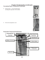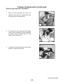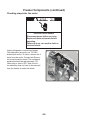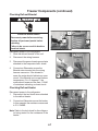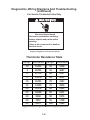
1
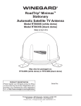
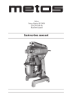
R-110
TECHNICAL EDUCATION
2010 Whirlpool 26’
SXS Refrigerators
GSF26C5EXW
GSF26C5EXY
GSS26C5XXA
GSS26C5XXB
GSS26C5XXW
GSS26C5XXY
GSF26C5EXS
GSF26C5EXT
JOB AID W10338921
FORWARD
This Job Aid, Whirlpool Gold 26’ SXS 2010 Part Number W10330404 has been compiled to
provide the recent information on design, features, operation, troubleshooting and repair procedures for 26’ SXS for 2010.
This Job Aid is not intended to replace or substitute for the Use and Care Guides or Tech Sheets
associated with any of the models covered. Refer to the Technical Service sheet shipped with
the refrigerator for detailed information for the unit you are servicing.

GOALS AND OBJECTIVES
The goal of this Job aid is to provide basic information that will enable the service technician to
properly diagnose malfunctions and repair 26” SXS refrigerators for 2010.
The objectives of this Job Aid are to:
• Understand and follow proper safety precautions.
• Successfully troubleshoot and diagnose malfunctions.
• Successfully perform necessary repairs.
• Successfully return the refrigerator to its proper operational status.
Specific components and procedures covered in this Job Aid are:
Grille Removal
Leveling
Door Alignment
Door Removal
Small 6 Cube Ice Maker
Dispenser
Thermistors
Air and Water Filters
Evaporator Fan
Defrost Heater
Defrost Bimetal
Overload Protector
Condenser Fan Motor
Start Module
Stealth Control
WHIRLPOOL CORPORATION assumes no responsibility for any repairs made on
our products by anyone other than authorized In-Home Service Professionals.
Copyright © 2010, Whirlpool Corporation, Benton Harbor, MI 49022
- ii -
TABLE OF CONTENTS
Page
GENERAL . . . . . . . . . . . . . . . . . . . . . . . . . . . . . . . . . . . . . . . . . . . . . . . . . . . . . . . . . . . . . . . 1-1
Safety. . . . . . . . . . . . . . . . . . . . . . . . . . . . . . . . . . . . . . . . . . . . . . . . . . . . . . . . . . . . . . . . . 1-1
Introduction Specifications and Overview. . . . . . . . . . . . . . . . . . . . . . . . . . . . . . . . . . . . . 1-2
SxS Model Number Interpretation. . . . . . . . . . . . . . . . . . . . . . . . . . . . . . . . . . . . . . . . . . . 1-3
6th Sense Technology. . . . . . . . . . . . . . . . . . . . . . . . . . . . . . . . . . . . . . . . . . . . . . . . . . . . 1-4
INSTALLATION REQUIREMENTS . . . . . . . . . . . . . . . . . . . . . . . . . . . . . . . . . . . . . . . . . . . . 2-1
Installation Instructions . . . . . . . . . . . . . . . . . . . . . . . . . . . . . . . . . . . . . . . . . . . . . . . 2-1, 2-7
REFRIGERATOR COMPONENTS . . . . . . . . . . . . . . . . . . . . . . . . . . . . . . . . . . . . . . . . . . . . 3-1
Disassembling Refrigerator Compartment Components. . . . . . . . . . . . . . . . . . . . . . . . . . 3-1
Disassembling Refrigerator Compartment Components –Water Filter Housing. . . . . . . . 3-3
Refrigerator Thermistor . . . . . . . . . . . . . . . . . . . . . . . . . . . . . . . . . . . . . . . . . . . . . . . . . . . 3-4
Accessing Water Reservoir. . . . . . . . . . . . . . . . . . . . . . . . . . . . . . . . . . . . . . . . . . . . . . . . 3-6
FREEZER COMPARTMENT AND ICE MAKER . . . . . . . . . . . . . . . . . . . . . . . . . . . . . . . . . . 4-1
Freezer Components. . . . . . . . . . . . . . . . . . . . . . . . . . . . . . . . . . . . . . . . . . . . . . . . . . . . . 4-1
Checking the Freezer Thermistor. . . . . . . . . . . . . . . . . . . . . . . . . . . . . . . . . . . . . . . . . . . . 4-1
Accessing Freezer Components . . . . . . . . . . . . . . . . . . . . . . . . . . . . . . . . . . . . . . . . 4-3, 4-4
Evaporator Component Identification. . . . . . . . . . . . . . . . . . . . . . . . . . . . . . . . . . . . . . . . . 4-4
Removing Evaporator Fan Motor. . . . . . . . . . . . . . . . . . . . . . . . . . . . . . . . . . . . . . . . . . . . 4-5
Checking evaporator Fan motor. . . . . . . . . . . . . . . . . . . . . . . . . . . . . . . . . . . . . . . . . . . . 4-6
Checking Defrost Bimetal. . . . . . . . . . . . . . . . . . . . . . . . . . . . . . . . . . . . . . . . . . . . . . . . . 4-7
Replacing the Defrost Heater. . . . . . . . . . . . . . . . . . . . . . . . . . . . . . . . . . . . . . . . . . . . . . . 4-8
Freezer Door Component Location. . . . . . . . . . . . . . . . . . . . . . . . . . . . . . . . . . . . . . . . . . 4-9
Ice maker – Emitter /Receiver Boards. . . . . . . . . . . . . . . . . . . . . . . . . . . . . . . . . . . . . . . 4-10
Component Identification. . . . . . . . . . . . . . . . . . . . . . . . . . . . . . . . . . . . . . . . . . . . . . . . . 4-12
Accessing New In Door Ice Maker. . . . . . . . . . . . . . . . . . . . . . . . . . . . . . . . . . . . . . . . . . 4-13
Ice Maker. . . . . . . . . . . . . . . . . . . . . . . . . . . . . . . . . . . . . . . . . . . . . . . . . . . . . . . . . . . . . 4-15
Modular Ice Maker & Ice Level Detector Service Sheet. . . . . . . . . . . . . . . . . . . . . . . . . 4-16
Disassembling the Ice Maker. . . . . . . . . . . . . . . . . . . . . . . . . . . . . . . . . . . . . . . . . . . . . . 4-17
Replacing Auger Motor and Related Components. . . . . . . . . . . . . . . . . . . . . . . . . . . . . . 4-19
Removing Auger Motor . . . . . . . . . . . . . . . . . . . . . . . . . . . . . . . . . . . . . . . . . . . . . . . . . . 4-20
Checking the Auger Motor. . . . . . . . . . . . . . . . . . . . . . . . . . . . . . . . . . . . . . . . . . . . . . . . 4-21
Removing Emitter and Receiver Boards . . . . . . . . . . . . . . . . . . . . . . . . . . . . . . . . . . . . . 4-21
Water Tube Routing. . . . . . . . . . . . . . . . . . . . . . . . . . . . . . . . . . . . . . . . . . . . . . . . . . . . . 4-22
DISPENSER AND USER INTERFACE . . . . . . . . . . . . . . . . . . . . . . . . . . . . . . . . . . . . . . . . .
Programming. . . . . . . . . . . . . . . . . . . . . . . . . . . . . . . . . . . . . . . . . . . . . . . . . . . . . . . . . . .
Stealth Control. . . . . . . . . . . . . . . . . . . . . . . . . . . . . . . . . . . . . . . . . . . . . . . . . . . . . . . . . .
Sleep Mode . . . . . . . . . . . . . . . . . . . . . . . . . . . . . . . . . . . . . . . . . . . . . . . . . . . . . . . . . . . .
Adjusting Temperature Set Points. . . . . . . . . . . . . . . . . . . . . . . . . . . . . . . . . . . . . . . . . . .
Adjusting Temperature Settings. . . . . . . . . . . . . . . . . . . . . . . . . . . . . . . . . . . . . . . . . . . . .
Freezer Temperature Setting. . . . . . . . . . . . . . . . . . . . . . . . . . . . . . . . . . . . . . . . . . . . . . .
Ice Dispenser. . . . . . . . . . . . . . . . . . . . . . . . . . . . . . . . . . . . . . . . . . . . . . . . . . . . . . . . . . .
Max Ice. . . . . . . . . . . . . . . . . . . . . . . . . . . . . . . . . . . . . . . . . . . . . . . . . . . . . . . . . . . . . . .
Dispenser Light . . . . . . . . . . . . . . . . . . . . . . . . . . . . . . . . . . . . . . . . . . . . . . . . . . . . . . . . .
- iii -
5-1
5-1
5-1
5-2
5-4
5-5
5-5
5-6
5-7
5-8
TABLE OF CONTENTS (continued)
Door Open Alarm . . . . . . . . . . . . . . . . . . . . . . . . . . . . . . . . . . . . . . . . . . . . . . . . . . . . . . . 5-9
Dispenser Lock . . . . . . . . . . . . . . . . . . . . . . . . . . . . . . . . . . . . . . . . . . . . . . . . . . . . . . . . 5-10
Cooling Off Mode. . . . . . . . . . . . . . . . . . . . . . . . . . . . . . . . . . . . . . . . . . . . . . . . . . . . . . . 5-11
Cooling On Mode. . . . . . . . . . . . . . . . . . . . . . . . . . . . . . . . . . . . . . . . . . . . . . . . . . . . . . . 5-11
Water Filter Status Light. . . . . . . . . . . . . . . . . . . . . . . . . . . . . . . . . . . . . . . . . . . . . . . . . . 5-12
Showroom Mode . . . . . . . . . . . . . . . . . . . . . . . . . . . . . . . . . . . . . . . . . . . . . . . . . . . . . . . 5-13
Accessing User Interface and Dispenser Components. . . . . . . . . . . . . . . . . . . . . 5-14, 5-17
MACHINE COMPARTMENT . . . . . . . . . . . . . . . . . . . . . . . . . . . . . . . . . . . . . . . . . . . . . . . . .
Machine Compartment Components. . . . . . . . . . . . . . . . . . . . . . . . . . . . . . . . . . . . . . . . .
Starting Device Operation . . . . . . . . . . . . . . . . . . . . . . . . . . . . . . . . . . . . . . . . . . . . . . . . .
Accessing Dual Water Valve . . . . . . . . . . . . . . . . . . . . . . . . . . . . . . . . . . . . . . . . . . . . . . .
Condenser Fan . . . . . . . . . . . . . . . . . . . . . . . . . . . . . . . . . . . . . . . . . . . . . . . . . . . . . . . . .
Drain Pan. . . . . . . . . . . . . . . . . . . . . . . . . . . . . . . . . . . . . . . . . . . . . . . . . . . . . . . . . . . . . .
Front Wheel. . . . . . . . . . . . . . . . . . . . . . . . . . . . . . . . . . . . . . . . . . . . . . . . . . . . . . . . . . . .
Control and Power Supply Boards. . . . . . . . . . . . . . . . . . . . . . . . . . . . . . . . . . . . . . . . . . .
6-1
6-1
6-3
6-4
6-5
6-6
6-7
6-8
DIAGNOSTICS, WIRING DIAGRAMS AND TROUBLESHOOTING . . . . . . . . . . . . . . . . . . 7-1
Voltage Test Points. . . . . . . . . . . . . . . . . . . . . . . . . . . . . . . . . . . . . . . . . . . . . . . . . . . . . . . 7-3
Thermistor Resistance Table . . . . . . . . . . . . . . . . . . . . . . . . . . . . . . . . . . . . . . . . . . . . . . . 7-6
Service Sheet. . . . . . . . . . . . . . . . . . . . . . . . . . . . . . . . . . . . . . . . . . . . . . . . . . . . . . . 7-7, 7-8
Product Specifications And Warranty Information Sources. . . . . . . . . . . . . . . . . . . . . . . . 7-4
- iv -
GENERAL
Safety
Observe all safety warnings and messages.
The Use and Care manual and Installation instructions that come with the product as well as stickers and literature attached to the refrigerator contain safety symbols. These symbols contain messages telling you of potential
hazards and explain how to reduce your chance of injury. The message will also tell you what can happen if the
instructions are not followed.
Your safety and the safety of others are very important.
We have provided many important safety messages in this manual and on your appliance. Always read and obey all safety
messages.
This is the safety alert symbol.
This symbol alerts you to potential hazards that can kill or hurt you and others.
All safety messages will follow the safety alert symbol and either the word “DANGER” or “WARNING.”
These words mean:
DANGER
WARNING
You can be killed or seriously injured if you don't immediately
follow instructions.
You can be killed or seriously injured if you don't follow
instructions.
All safety messages will tell you what the potential hazard is, tell you how to reduce the chance of injury, and tell you what can
happen if the instructions are not followed.
IMPORTANT SAFETY INSTRUCTIONS
WARNING: To reduce the risk of fire, electric shock, or injury when using your refrigerator,
follow these basic precautions:
Use nonflammable cleaner.
Plug into a grounded 3 prong outlet.
Keep flammable materials and vapors,
Do not remove ground prong.
Do not use an adapter.
such as gasoline, away from refrigerator.
Do not use an extension cord.
Use two or more people to move and install
Disconnect power before servicing.
refrigerator.
Replace all parts and panels before operating.
Disconnect power before installing ice maker
(on ice maker kit ready models only).
Remove doors from your old refrigerator.
Use a sturdy glass when dispensing ice
(on some models).
SAVE THESE INSTRUCTIONS
1-1
Dimensions
Inches.
Introduction Specifications
and Overview
Capacity
Dimensions
Carton
Depth
Capacity
Dimensions
Carton
Height
Carton
Depth
Capacity
Carton
Width
Carton
Carton Height
Depth
Cutout
Depth (in)
Carton Height
Width
Carton
Cutout
Height
(in)
Cutout
Depth (in)
Carton Width
Cutout
Width (in)
Cutout
(in)
Cutout Height
Depth (in)
Depth
Cutout
Cutout Width
Height(in)
(in)
Height
Depth
Cutout Width (in)
Width
Height
Depth
Depth
Closed Excluding
Width
Height
Handles
Depth
Width Closed Excluding
Depth
Closed Including
Handles
Handles
Depth
Closed Excluding
Depth
Closed Including
Handles
Depth
Excluding Doors
Handles
Depth Closed Including
Depth
With
Door Open
Depth
Excluding
Doors90
Handles
Degree
Depth
Door Open
Depth With
Excluding
Doors90
Gross
Weight
Degree
Depth With Door Open 90
Height
To Top Of Cabinet
Gross
DegreeWeight
Height
To
HeightWeight
To Top
Top Of
Of Door
Cabinet
Gross
Hinge
Height
Height To
To Top
Top Of
Of Door
Cabinet
Hinge
Height To Top of Door Trim
Height To Top Of Door
Hinge
Height
To TopOpen
of Door
Width Doors
90 Trim
Degrees
Height
To TopOpen
of Door
Width Doors
90 Trim
Width
of Cabinet Only
Degrees
Width Doors Open 90
Width
with
Doors Only
Closed
Width
of Cabinet
Degrees
Capacity Width
Doors Only
Closed
Width with
of Cabinet
Gross Weight
Width with Doors Closed
26.360
26’ Dimensions
Inches.
35
26.360
Inches.
71
1/4
35
26.360
38
71
35 1/4
29
13/16
38
71 1/4
69
5/16
29
38 13/16
36
1/16
69
29 5/16
13/16
36
36
69 1/16
5/16
69
1/4
36
36 1/16
35
69 7/16
1/4
36
35
33 7/16
1/2
69
1/4
35
33 7/16
1/2
36
33 1/2
36
29 3/8
36
29 7/8
3/8
50
29
3/8
50
2987/8
68
5/8
50
2987/8
68 15/16
5/8
68
298
68
68 5/8
15/16
69 1/4
68 15/16
69 1/4
37 3/4
69 1/4
37 7/16
3/4
35
35
37
35 3/4
7/16
26.360 C.F.
35
35 3/4
7/16
298 LBS.
35 3/4
1-2
1-3
Introduction Specifications and Overview (continued)
6th Sense Technology
6th Sense software makes an estimation of
the actual food temperature inside the refrigerator and freezer compartment and adjusts
cooling to allow the food packages to return
their initial temperature faster during pull
down, door openings, or heavy food load. 6th
Sense algorithm runs in both freezer compartment and refrigerator compartment and
each contains 3 routines: Trigger, Package
Estimator, and Defrost Manager.
Trigger routine is executed every 2.5 seconds while Package Estimator and Defrost Manager
are executed every 10 seconds. The trigger routine is divided into two subroutines: door monitoring and temperature monitoring. Trigger parameters and performance parameters reside in
the User Interface board, the actual 6th sense algorithm resides in Gemini Flash board.
Package Estimator routine computes an estimation of food in FC and RC according to Thermistor reading and door status. Package estimator is run when the User Interface sends the
required parameters to Gemini flash and sets the 6th Sense Enable bit to true. If 6th Sense is
needed, it will call for additional cooling by turning on compressor, damper and evaporator fan.
Defrost manager is composed of two main states: Normal and 6th Sense.
When 6th Sense routine is active, defrost will be inhibited based on the control parameters settings to allow food temperature recovery.
1-4
INSTALLATION REQUIREMENTS
Installation Instructions
This new SXS platform requires different installation steps and adjustments than current SXS refrigerators. Review the
Use and Care manual and instruction sheets shipped with the product prior to installation. See the following examples:
Door Removal, Leveling and Alignment
hex
2-1
Installation Instructions (continued)
Installation - Example
hex
2-2
Installation Instructions (continued)
Installation - Example (continued)
2-3
Installation
Refrigerators are shipped with the handles
packed in the refrigerator door.
1. Remove the handles from the door and
unwrap.
1
2. The instruction sheet and a Hex key tool are attached to the handle. Review the
instruction sheet.
2
3. Install the handle on the mounting studs with the hex screws facing to the center.
3
4. Hold the handle tight against the door as you tighten the screws. The handle will pull in tight against the door as the screw is tightened.
4
2-4
Installation Instructions (continued)
Installation (continued)
Removing Grille
WARNING
Electrical Shock Hazard
Disconnect power before servicing.
Replace all parts and panels before
operating.
Failure to do so can result in death or
electrical shock.
1. Disconnect power to the refrigerator.
Remove 2 ¼” screws
The grille is held in place with 2 ¼” screws.
2. Remove screws
2
Remove grille
3. Open the doors 90 degrees perpendicular to the cabinet to remove the grille.
3
Components Located Behind Grille
Water Tubes
Leveler Leg
Center Roller
Wiring Harnesses
Leveler Leg
2-5
Installation Instructions (continued)
Removing Freezer Door
WARNING
Electrical Shock Hazard
Disconnect power before servicing.
Replace all parts and panels before
operating.
Failure to do so can result in death or
electrical shock.
2
1. Unplug or disconnect the refrigerator from the power supply.
onnect water tubes form the
de of the
connector
2. Remove the screws securing the wire
harnesses to the cabinet.
32
3. Disconnect water tubes form the door side of the connector.
4. Unplug the three wire harnesses plugged into the terminal board.
43
5. Remove strain relief from the wire harness.
This will allow the harness to pass through the hole in the hinge.
5
2-6
Installation Instructions (continued)
Removing Freezer Door Upper Hinge
6. Remove Two 3/16” hex key screws (A). Do not remove or loosen the other two screws (B).
7. Keep the door closed and lift off the hinge.
B
A
A
B
65
WARNING
Excessive Weight Hazard
Use two or more people to lift the freezer
door.
Failure to do so can result in back or
other injury.
Lift off the hinge
76
8. Have another person open the freezer door and lift up slowly.
87
9. As the door is lifted guide the wiring
harnesses and water tubes through the hinge.
98
10. Lift the door straight up to prevent
damage and kinking of the water tube.
Note: When assembling, always use 2
people and make sure not to crimp the water
tubes when installing through the hinge hole.
9
10
2-7
—NOTES—
2-8
REFRIGERATOR COMPONENTS
Refrigerator Compartment
Light Bulbs
Air Damper
Air Filter
Water Filter
Disassembling Refrigerator Compartment Components
WARNING
2
1
Electrical Shock Hazard
Disconnect power before servicing.
Replace all parts and panels before
operating.
Failure to do so can result in death or
electrical shock.
1. Disconnect power to the refrigerator.
32
2. Open the water filter door and remove the filter.
3. Open the air filter door and remove the filter.
4. Remove the ¼” screw securing the air damper cover to the cabinet.
43
3-1
Refrigerator Compartment (continued)
3
5. Remove the air damper cover.
54
6. Remove the ¼” screw securing the air filter housing to the cabinet and remove.
65
7. Disconnect the wiring harness and remove the air damper assembly.
76
8.
Check the seal around the damper
housing for any damage or misplace
ment. Replace or reposition seal as
needed.
87
3-2
Refrigerator Compartment (continued)
Disassembling Refrigerator
Compartment Components –
Water Filter Housing
Remove the water filter as explained earlier.
1. Remove the ¼” screw securing the filter cover to the filter body.
1
2. Remove the cover.
2
3. Remove the ¼” screw securing the filter body to the cabinet wall.
3
4. To replace the filter housing, disconnect the water tubes in the back of the
refrigerator and remove Permagum seal. Pull the filter housing and water tubes through the opening in the cabinet and replace.
4
3-3
Refrigerator Compartment (continued)
Refrigerator Thermistor
The refrigerator Thermistor is a variable resistance device connected to the control board.
The temperature of the refrigerator compartment causes the resistance of the Thermistor to
change. The resistance is monitored by a circuit on the control board which controls the operation of the cooling system. The Thermistor is located on the right side of the refrigerator cabinet
attached to the back of the cover labeled 6th sense.
Refrigerator Thermistor
WARNING
Electrical Shock Hazard
Disconnect power before servicing.
Replace all parts and panels before
operating.
Failure to do so can result in death or
electrical shock.
1. Disconnect power to the refrigerator.
2. Disconnect the wiring harness from
connector P6 on the control board.
3. Connect an Ohmmeter across the Orange and Blue/White wires in the disconnected wiring harness and measure the
resistance.
4. Compare the resistance measured to the value listed on the tech sheet shipped with the refrigerator. Replace Thermistor if needed.
3-4
Refrigerator Compartment (continued)
Replacing Refrigerator Thermistor
1. Depress the tabs on either end of the Thermistor cover and remove.
2.
To replace the Thermistor order replace
ment Thermistor kit through the normal part ordering system by model number. Follow the instructions supplied with the kit.
1
2
3-5
Refrigerator Compartment (continued)
Disassembling Refrigerator Compartment Components – Accessing Water
Reservoir
Disassembling Refrigerator Compartment Components – Accessing Water Reservoir
1. The light bulb cover is very flexible and can be bent to release the 4 tabs that extend into the cabinet wall and remove.
1
2. To replace the water reservoir, Shut off water supply.
3. Remove the ¼” hex head screw and the wire ties securing the reservoir to the cabinet.
3
2
4. Disconnect the water tube connected to the dual water valve located in the
machine compartment and disconnect the water tube fitting on the lower left hand corner of the reservoir. Pull out the water reservoir and the water tube routed through the opening in the cabinet.
Replace the reservoir.
A vacuum relief is located below the water
reservoir. The purpose of the relief is to allow
pressure to equalize between the inside and
outside of the refrigerator.
3-6
4
3
Freezer Compartment and Ice Maker
Freezer Components
Freezer Thermistor
The freezer Thermistor is a variable resistance device connected to the control board. The
temperature of the freezer compartment causes the resistance of the Thermistor to change.
The resistance is monitored by a circuit on the control board which controls the operation of
the cooling system. The Thermistor is located on the left side of the freezer cabinet attached to
the back of the cover labeled 6th sense.
Checking the freezer Thermistor
WARNING
Electrical Shock Hazard
Disconnect power before servicing.
Replace all parts and panels before
operating.
Failure to do so can result in death or
electrical shock.
1. Disconnect power to the refrigerator
2. Disconnect the wiring harness from
connector P6 on the control board.
3. Connect an Ohmmeter across the 2 Black wires in the disconnected
wiring harness and measure the
resistance.
4. Compare the resistance measured to the value listed on the tech sheet shipped
with the refrigerator. Replace Thermistor if needed.
4-1
Temp F Resistance
-10
31402
-5
26704
0
22774
5
19476
10
16701
15
14359
20
12378
25
10698
30
9268
40
7007
45
6115
Temp F Resistance
50
5348
55
4687
60
4117
65
3624
70
3197
75
2826
80
2503
85
2221
90
1974
95
1758
100
1569
Freezer Components (continued)
Replacing Freezer Thermistor
1. Depress the tabs on either end of the
Thermistor cover and remove.
2. To replace the Thermistor order replacement Thermistor kit through the normal
part ordering system by model number.
Follow the instructions supplied with the
kit.
1
2
4-2
Freezer Components (continued)
Accessing Freezer Components
WARNING
Electrical Shock Hazard
Disconnect power before servicing.
Replace all parts and panels before
operating.
Failure to do so can result in death or
electrical shock.
2.
1
1. Unplug refrigerator or disconnect power.
Remove food and shelving.
2. Pull off the light cover located in the top
left hand corner of the freezer compartment.
2
3.
3. Remove the ¼” hex head screw below
the light bulb.
4. Pull the top of the air duct cover out at the
top and lift up to remove.
4.
3
5. The bottom of the duct has 2 slots that
slid onto the top of the evaporator
cover.
5.
4
4-3
Freezer Components (continued)
Accessing Freezer Components (continued)
5. Remove the 4 - 1/4” hex head screws
securing the evaporator to the cabinet.
5
6. Pull out the evaporator cover.
6
Evaporator Component Identification
Evaporator Fan
Assembly
Wiring Harness
Connection
Defrost Bimetal
Capillary
Tube
Inlet
Cap tube
Inlet
Defrost Heater
Chassis Ground
Connection
Drain Pan
4-4
Freezer Components (continued)
Removing Evaporator Fan Motor
1. Slide out the evaporator fan motor assembly from the built in cabinet rails and
disconnect the wiring harness.
1
2. To change the fan blade, pull the blade
off the shaft and replace. When installing
the blade, push the blade down on the
shaft until it bottoms out.
2
3. Unclip the mounting bracket from the fan
shroud to remove the motor.
3
4-5
Continued next page.
Freezer Components (continued)
Checking evaporator fan motor
WARNING
Electrical Shock Hazard
Disconnect power before servicing.
Replace all parts and panels before
operating.
Failure to do so can result in death or
electrical shock.
Unplug refrigerator or disconnect power.
The evaporator fan motor is a 120 VAC
shaded pole motor. To check, remove the 2
wires from the motor. Connect an Ohmmeter across the motor leads. The resistance
measured should be approximately 135
Ohms plus or minus 10%. Note: the motor assembly does not have to be removed
form the freezer to make this check.
4-6
Freezer Components (continued)
Checking Defrost Bimetal
WARNING
2
Electrical Shock Hazard
Disconnect power before servicing.
Replace all parts and panels before
operating.
Failure to do so can result in death or
electrical shock.
1
Disconnect power to the refrigerator.
1. Slide the defrost bimetal off the coil.
2. Disconnect the wiring harness.
3. Disconnect the green chassis ground wire
attached to the evaporator heat shield.
4. Connect an Ohmmeter across the
Bimetal wires inserted into the wiring
harness connector. If the bimetal is
warm the meter should indicate an open
circuit. If the Bimetal is at normal freezer
temperature -5 to +5 degrees F, the
meter should measure less than 1 OHM
of resistance indicating a closed circuit.
4
Checking Defrost Heater
Disconnect power to the refrigerator.
1. Disconnect the two black wires attached
to the defrost heater.
2. Connect an Ohmmeter across the heater.
In this example the resistance measured
is 31.6 OHMS.
Note: Refer to the tech sheet for the refrigerator being tested for the resistance of the
heater.
2
4-7
3
Freezer Components (continued)
Replacing the defrost heater
Disconnect power to the refrigerator.
1. Remove evaporator cover as explained
earlier.
2. Disconnect the two black wires connected to the defrost heater.
3. Disconnect the green chassis ground wire
attached to the evaporator heat shield.
4. Grasp the bottom of the heat shield all
pull out. The heat shield is fastened to the
cabinet with clips and will pull out easily.
5. Inspect the heat shield and reposition
any clips that might have been dislodged
during removal.
6. Pull out the defrost heater from the bottom of the evaporator and replace.
4-8
Freezer Components (continued)
Freezer Door Component Location
A label on the freezer instructs the customer the ice maker ON/OFF switch is located
behind the ice storage bin.
Ice maker
Ice maker Specifications
•
•
•
•
•
•
•
•
IDI XXL design uses W10122576 120VAC ice maker
6 cavity small cube ice maker (similar to Tempest ice maker, but mounts in freezer door and has splash provisions)
Fill volume: 49cc
Harvest frequency: 42 minutes normally, 35 minutes Accelerice
Ice bin capacity 4.0 lbs.
35 harvests to fill ice bin – about 24 hrs.
Non-IDI XXL design uses current production ice maker W10122556.
The module is still the Molex module that we use on nearly every ice maker in the field.
4-9
Freezer Components (continued)
Ice maker – Emitter /Receiver Boards
The emitter board emits an infrared beam.
When the eye on the receiver board sees
the beam a circuit is completed indicating
the ice bin is in place and not full. This signal is sent to the control board and the ice
maker is energized. If the beam is not seen
by the receiver board, the control board
shuts off the ice maker.
Emitter
Receiver
ON
1. With the switch on the emitter board in
the ON position, the window covering the
emitter beam is opened.
1
2. With the switch on the emitter board in
the OFF position, the window covering
the emitter beam is closed.
Window
Open
OFF
2
Window
Closed
3
Window
Open
3. With the ice bin installed it forces the
receiver door closed aligning a window
in the door with the eye on the receiver
board.
4. When the ice bin is removed, the door
opens and blocks the signal from the
emitter.
4
4-10
Window
Blocked
Freezer Components (continued)
WARNING
Electrical Shock Hazard
Disconnect power before servicing.
Replace all parts and panels before
operating.
Failure to do so can result in death or
electrical shock.
1. Disconnect power to the refrigerator.
2. Depress the ice bin latch and remove the
ice bin.
2
Emitter
Receiver
Auger Motor
4-11
Freezer Components (continued)
3. Remove 2 - 1/4” screws securing the
housing to the inner door panel. Lift the
housing up and out to remove.
3
4. When assembling insert the tabs located
on the top of the housing into the slots on
the inner door panel.
4
Component Identification
Fill Tube Heater Harness
Fill Tube
Fill Tube
Fill Trough
Ice Maker
Wire Harness
Emitter
New Compact
6 cavity Ice Maker
Receiver
Auger Motor
Coupling
4-12
Freezer Components (continued)
Accessing New In Door Ice Maker
5. Remove the ice maker wire harness
cover and disconnect the harness.
5
6. Disconnect the wire harness to the emitter and receiver boards.
6
7. Remove 2 - 1/4” screws under the ice
maker.
7
8. Slide out the ice maker to remove.
8
9. Remove 3 - ¼” screws to remove housing from the ice maker mold.
4-13
Freezer Components (continued)
Accessing New In Door Ice Maker
10. Unplug the wire harness from the ice
maker head.
10
11. Slide off the Hi Limit control from the
mold.
11
4-14
Freezer Components (continued)
Ice maker
New Six Cavity Ice Maker Component Identification
Bracket
Head
Ice Stripper
Ejector Blade
Module
Mold
Components
Disassembling the ice maker.
1.
Remove the ice maker cover. A module similar to the existing product is used. The module is checked exactly as the
current module.
Refer to ice maker tech sheet shipped with the product” See next page.
n
2. Remove three screws that secure the module to the head.
m
2
V
1
H
L
t
Jumper “T” to “H” to start harvest cycle
Continued next page
4-15
3
h Sheet
Do not
DANGER
Freezer Components (continued) WARNING
DANGER
WARNING
Electrical Shock Hazard
Electrical Shock Hazard
nly authorized technicians should perform diagnostic
oltage measurements. Electrical Shock Hazard
Only authorized technicians should
fter performing
voltage
measurements,
perform
diagnostic
voltagedisconnect
measurements.
ower before servicing.
After performing voltage measurements,
ailure to follow
these instructions
can result
in death or
disconnect
power before
servicing.
ectrical shock.
Failure to follow these instructions can
result in death or electrical shock.
Disconnect power before servicing.
Electrical Shock Hazard
Replace
parts and
panels before
Plug
into a all
grounded
(earthed)
outlet.operating.
Replace
before
Failurealltoparts
do soand
canpanels
result in
death or electrical s
operatating.
Failure to do so can result in death or
electrical shock.
Voltage Measurement Safety Information
When performing live voltage measurements, you must do the following:
Verify the controls are in the off position so that the appliance does not start when energized.
Allow enough space to perform the voltage measurements without obstructions.
Keep other people a safe distance away from the appliance to prevent potential injury.
Always use the proper testing equipment.
After voltage measurements, always disconnect power before servicing.
To check for proper voltage, complete the following steps:
1. Disconnect power.
2. Connect voltage measurement equipment.
3. Reconnect power and confirm voltage reading.
4. Disconnect power after performing voltage measurement.
4-16
Freezer Components (continued)
4-17
Freezer Components (continued)
Disassembling the ice maker (continued)
2
3. Separate the module from the head.
3
4. Remove two screws on the bottom of the
ice maker head and separate the head
from the mold. The thermostat can be
removed at this point.
4
5.
When replacing the thermostat apply a
coating of Alumilastic to the mold.
This will provide a thermal bond between
the mold and thermostat.
5
4-18
Freezer Components (continued)
Replacing Auger Motor and Related
Components
1. Remove 2 screws and lift off cover.
1
2. Remove the coupling by lifting straight up.
A spring is captured under the coupling.
Coupling
Spring
2
3. To access the motor remove the 4 - 1/4”
screws securing the chute to the
housing.
3
4. Lift out the chute. The chute may require
some effort to remove because of the
foam seal around the chute tube.
4
5. Inspect seal and repair or replace if
necessary before reassembly.
5
4-19
Foam
Seal
Spring
Freezer Components (continued)
Removing Auger Motor
6. Remove 4 - 1/4” screws securing the motor to the housing .
6
7. Lift up the auger motor and disconnect the
wire harness.
7
Condensate Drain
Under normal operating conditions, moisture may accumulate in the bottom of the auger motor
housing. A drain hole is provided to allow water to pass through the inner door panel and drop
onto the lower shelf, see figure 2.
Auger Motor Compartment
Auger Motor
Drain Hole
Auger Motor
Compartment
Drain Outlet
Figure 1
Figure 2
4-20
Freezer Components (continued)
Checking the Auger Motor
WARNING
Electrical Shock Hazard
Disconnect power before servicing.
Replace all parts and panels before
operating.
Failure to do so can result in death or
electrical shock.
Unplug refrigerator or disconnect power.
Connect an Ohmmeter across the 2 motor
terminals and measure the resistance. The
resistance should be approximately 210
Ohms plus or minus 10%.
Removing Emitter and Receiver Boards
Release 3 tabs to remove the emitter
and receiver boards from the housing.
Emitter
Receiver Board
Emitter Board
4-21
Freezer Components (continued)
Water Tube Routing
Water Routing: the home water supply is
connected to the isolation valve. The outlet
of the isolation valve connects to the water
filter located in the refrigeration compartment. The outlet of the filter connects to the
inlet of the water reservoir. The water reservoir outlet connects to the inlet of the dual
valve.
Freezer Door
The ice maker fill tube and the water dispenser tube are routed through the hole in
the lower freezer door hinge.
4-22
DISPENSER AND USER INTERFACE
Stealth Control
Figure 1 – Whirlpool Stealth User Interf ace/Blue LED’s except as noted.
The Icons used on this Whirlpool user interface display are similar to those used on other SXS
models but not identical. The basic operation and programming is the same.
5-1
Programming (continued)
Figure 3 – KitchenAid Interface Icon Identification
Figure 3 depicts all the ICONS and Text located on the Display. Specific Icons will
be displayed at different steps during programming as explained in this manual.
Sleep Mode
The display screen on the dispenser control panel will turn off automatically and
enter “sleep” mode when the control buttons and dispenser levers have not been
used for 2 minutes or more. See figure 4.
Figure 4 – Hibernate/Sleep Mode Screen
While in “sleep” mode, the display is dark
5-2
Programming (continued)
Figure 5
Pressing any control button will activate the “Normal/Home ”
display screen, without changing any settings. See figure 5. After activation,
changes to any settings can then be made. If no changes are made within 2
minutes, the display will re-enter “sleep” mode.
Factory Preset Temperatures
The refrigerator and freezer controls are preset at the factory. The factory
recommended set points are 37°F (3°C) for the refrigerator and 0°F (-18°C) for the
freezer.
To View and Adjust Set Points:
Press and hold the TEMPERATURE button for 3 seconds. When adjust mode is
activated, the display screen shows the refrigerator set point and
“REFRIGERATOR” appears in the display. See figure 6.
5-3
Programming (continued)
Adjusting Temperature Set Points:
Figure 7
Pressing and holding TEMPERATURE starts a 3 second countdown. During the
countdown using the dispenser cancels the countdown and no dispensing is permitted.
The number 3 blinks 3 times and an invalid tone sounds 3 times,. The user has to release both
the pad and the button and press the button again to start the countdown over.
During the countdown, pressing any other button or releasing the pad cancels the countdown.
The user has to start over. Please note: the blinking and toning is synchronized so that the
moment the number ‘3’ blinks, the tone is sounded. After 3 seconds, the TEMPERATURE
shows up with the
CURRENT refrigerator setting.
See figure 7.
Pressing TEMPERATURE changes between the refrigerator and freezer compartments and
displays the current setting. Pressing the ICE MODE pad or after 60 seconds of no activity, the
display will revert back to the normal screen.
5-4
Programming (continued)
Figure 8
Adjusting Temperature Settings
Press the LOCK pad to raise the temperature set point or press the MAX ICE pad to lower the
temperature set point.
See figure 8.
IMPORTANT: When the temperature is changed, the word “CONFIRM” above the filter reset
pad illuminates and will flash without an audible tone constantly until user presses RESET
FILTER, ICE MODE or after 60 seconds of inactivity. If the user presses TEMPERATURE
to change compartments, CONFIRM still flashes if one of the temps has been changed.
NOTE: To view Celsius temperatures, press the LIGHT button when adjust mode is activated.
Freezer Temperature Setting
Figure 9
After viewing (and adjusting if desired) the refrigerator set point, press TEMPERATURE to
change the display to show the freezer set point. When the zone has been changed, “FREEZER” appears on the display screen. Press LOCK to raise the set point, or press MAX ICE to
lower the set point. When you have finished viewing (and adjusting if desired) both the refrigerator and freezer set points, press FILTER to save the settings. See figure 9.
5-5
Programming (continued)
Figure 10
Ice Dispenser:
Ice dispenses from the ice maker storage bin in the freezer when the dispenser lever is
pressed. The ice maker can produce both crushed and cubed ice. Before dispensing ice,
select which type of ice you prefer by pressing the ICE MODE button. The display screen
indicates which type of ice is selected. See figure 10.
For crushed ice, cubes are crushed before being dispensed. This may cause a slight delay
when dispensing crushed ice. Noise from the ice crusher is normal, and pieces of ice may vary
in size. When changing from crushed to cubed, a few ounces of crushed ice will be dispensed
along with the first cubes.
NOTE: Ice may continue to dispense for up to 10 seconds after removing the glass from the
lever. The dispenser may continue to make noise for a few seconds after dispensing.
5-6
Programming (continued)
Figure 11
Max Ice:
The Max Ice feature assists with temporary periods of heavy ice use by increasing ice
production over a 24-hour period.
IMPORTANT: This feature only works if the ice maker is turned on. Press MAX ICE to turn
on this feature. When the feature is on, the Max Ice icon will appear on the dispenser display
screen. See figure 11.
The Max Ice setting will remain on for 24hours unless manually turned off. To manually turn
off the Max Ice feature, press MAX ICE again or adjust the freezer temperature set point. The
MAX ICE icon will disappear when the feature is off.
NOTE: If increased ice production is desired at all times, change the freezer set point to a
lower setting. Setting the freezer to a colder temperature may make some foods, such as ice
cream harder.
5-7
Programming (continued)
Figure 12
Dispenser Light:
When you use the dispenser, the light will automatically turn on. If you want the light to be on
continuously, you may choose either ON or DIM.
The display screen indicates which mode is selected. See figure 12.
ON: Press LIGHT to turn the dispenser light on at 100%
DIM: Press LIGHT a second time to select DIM mode. The dispenser light will remain on, but at
a lower 50% intensity.
OFF: Press LIGHT a third time to turn the dispenser light off
Note: If the setting is changed it will remain that way.
5-8
Programming (continued)
Figure 13
Door Open Alarm
The Door Open Alarm feature sounds an alarm when the refrigerator or freezer door is open
for 5 minutes and the product cooling is turned on. The alarm will repeat every 2 minutes.
Close both doors to turn it off. The feature then resets and will reactivate when either door is
left open again for 5 minutes.
Details:
When a door is open for 5 minutes and the cooling function is on:
The Door Open Icon and the normal screen is displayed.
The Door Open chime is sounded 3 times.
The Door Open Icon appears and blinks 7 times and then becomes constant.
If a door is left open, every 2 minutes, the Door Open chime sounds 3 times, the Door Open
icon blinks 7 times and ten becomes constant.
NOTE: Since inactivity to sleep is also 2 minutes, the door open situation shall over ride the
sleep mode. In other words, the user interface will not go to the sleep mode if it is in the Door
Open mode.
When the door open alert condition is met (door open for 5 min), pressing any button on the
control panel at any time will turn off the Door Open Alert Chime.
The other door open functions, flashing door open icon, and the door reset timer continue until
the next door open alert occurs. This will continue until the both door are closed.
NOTE: To mute the audible alarm while keeping the doors open, such as while cleaning the
inside of the refrigerator, press any button on the control panel. The alarm sound will be temporarily turned off, but the Door Open icon will still be displayed on the dispenser control panel.
See figure 13.
5-9
Programming (continued)
Figure 14
Dispenser Lock:
The dispenser can be turned off for easy cleaning or to avoid unintentional dispensing by small
children and pets.
NOTE: The lock feature does not shut off power to the refrigerator, to the ice maker, or to the
dispenser light. It simply deactivates the controls and dispenser levers.
Details:
Pressing and holding LOCK starts a 3 second countdown. During the countdown, using the
dispenser cancels the countdown and no dispensing is permitted. During the countdown
pressing any other button or releasing the Lock button cancels the countdown.
After 3 seconds, the user interface is locked. See figure 14. No functions will occur during
cooling off. No status is displayed except for LOCK, Door Open, and Cooling Off . Pressing
any button or pad (except for LOCK or the COOLING OFF key dance ) will wake up the lock
screen if it has gone to sleep. The Lock icon will blink 3 times and the “invalid” tone sounds 3
times.
Pressing and holding LOCK for 3 seconds unlocks the user interface and the normal screen
(if cooling is not off) is displayed depicting the ice mode, light status, lock status, or any alert
icons exactly as before it was locked.
5-10
Programming (continued)
Figure 15
Cooling Off Mode
Pressing and holding both LOCK and RESET FILTER simultaneously, see figure 15, starts a
3, 2, 1 second countdown. During the countdown, using the dispenser cancels the countdown
AND no dispensing is permitted.
After 3 seconds, the ‘cooling off’ icon appears and flashes 7 times then remains on. All the rest
of the icons including door open turn off.
Exception: if the UI is locked the user can still turn cooling off. The ‘COOLING OFFF’ icon will
be displayed along with the lock icon. The only keys available to the user are the lock key to
unlock the control which returns to the standard cooling mode. When any other key is pressed,
an error beep will be sounded.
If the customer is in “normal mode” (not in locked mode) and the customer turns cooling off,
only the cooling off icon will show. The only keys available to the customer is the cooling on/
off key dance combination. When any other keys are pressed, an error beep will be sounded.
The cooling off screen will stay on all the time and does not go to sleep. If cooling is off when
power is interrupted, it will remain in the cooling off mode when power is restored.
During “COOLING OFF” (if the UI is not locked), ice and water dispensing is allowed.
Cooling On Mode
Pressing and holding LOCK and RESET FILTER again for 3 sec turns the cooling on. After
cooling is turned on, the normal screen is displayed with the ice mode, light status, lock statue,
filter status, or any alerts icons displayed exactly as before cooling was shut off.
5-11
Programming (continued)
Figure 16
Water Filter Status Light:
The water filter status light will help you know when to change your water filter.
When the dispenser control panel’s water filter status display changes to “ORDER,” this tells
you that it is almost time to change the water filter cartridge.
Replace the water filter cartridge when the water filter status display changes to “REPLACE.”
The filter should be replaced at least every 6 months depending on your water quality and usage.
NOTE: If water flow to your water dispenser or ice maker decreases noticeably, change the
filter sooner. After changing the water filter, reset the status light.
Details:
Pressing and holding RESET FILTER starts the 3 seconds countdown. Using the dispenser
cancels the countdown AND no dispensing is permitted. The number ‘3’ blinks 3 times and the
‘invalid’ tone sounds 3 times and user has to release both the pad and the button and press
the button again to start it over
After 3 seconds, the BLUE WATER BARS in the Icon flash and an audible tone sounds 3
times. When the system is reset, the “ORDER” and “REPLACE” icons will disappear from the
display screen. See figure 16.
Note: Users can reset the filter status at any stage.
5-12
Programming (continued)
Figure 17
Showroom Mode:
Pressing and holding LIGHT and MAX ICE starts a 3 second countdown. During the countdown, pressing any other button or releasing a pad cancels the countdown.
Details:
After 3 seconds, the control enters the showroom mode and the cooling system turns off.
When in the showroom mode, cooling off and WFI icons stay off all the time, while the Door
Open icon appears whenever door is open, however there is no door open audible alert.
No ice or water dispensing is allowed , an ‘invalid’ tone sounds if a pad is pressed or pressed
and held.
User is not allowed to turn cooling on or off if attempted. invalid tone sounds.
Pressing ICE MODE toggles cubed and crushed,
Pressing LIGHT toggles off/on/dim and lighting changes accordingly.
The user can enter the Temperature Setting menu, which works the same as previously described and the temperature will be stored. However, the moment the showroom mode is exited, the temperature will be set back to default.
After 1 minute in a temperature screen without activity the control returns to the normal
screen.
Please note that ‘cooling off’ text will not be lit in the showroom mode
Note: The user interface will not go to sleep under any circumstances.
Exiting the Showroom Mode:
Pressing and holding LIGHT and MAX ICE again for 3 sec OR unplugging and plugging in the
power cord exits the showroom mode and returns to normal operation.
5-13
Dispenser Components
Accessing User Interface and
Dispenser Components
WARNING
Electrical Shock Hazard
Disconnect power before servicing.
Replace all parts and panels before
operating.
Failure to do so can result in death or
electrical shock.
1.Disconnect power to the refrigerator.
2.Remove the drip tray and the grille.
2
Location of tabs
3
3.Release 3 locking tabs securing the user interface to the dispenser housing.
5-14
Dispenser Components (continued)
4. Drop down the User Interface board.
4
5. Remove the wire harnesses.
5
6. Remove the 4 screws securing the
dispenser housing to the door panel.
6
7. Disconnect the water tube from the
dispenser assembly.
7
5-15
Dispenser Components (continued)
8. Remove 2 - 1/4" hex head screws
securing the dispenser assembly to the door panel.
8
9. Remove the wiring harnesses from the dispenser bracket. Remove the wire
harnesses.
9
Lef t Clip
10.Release the retaining clips on the left and right side of the dispenser assembly.
Right Clip
10
2"
11. Pull the top of the dispenser housing out about 2” to allow removal of the
dispenser assembly.
11
12.Remove two screws to replace the
dispenser motor.
5-16
Dispenser Components (continued)
13. The dispenser door can be snapped out to replace.
13
NOTE: The door can be replaced without
removing the assembly.
Depress Here
14. To replace a switch, depress the release in the center slot and slide off the switch.
Slide Switch
5-17
—NOTES—
5-18
MACHINE COMPARTMENT
WARNING
Electrical Shock Hazard
Disconnect power before servicing.
Replace all parts and panels before
operating.
Failure to do so can result in death or
electrical shock.
Unplug refrigerator or disconnect power."
Gum Seal Wrapped
Around Water Tubes
Water Tubes to
Water Filter.
Power and Control
Boards Cover
Water Tubes to
Water reservoir
Gum Seal
Inlet Water
Valve
Compartment
Cover
Control Board
Power Supply
Board
Heat Loop
Inlet Water Valve
Start Module
Discharge Line
Suction Line
Dual Valve
Condenser
Stepper Motor
6-1
Machine Compartment Components
WARNING
Electrical Shock Hazard
Disconnect power before servicing.
Replace all parts and panels before
operating.
Failure to do so can result in death or
electrical shock.
2
1. Disconnect power to the refrigerator.
2. Remove the ¼” screws securing the fiber cover to the cabinet.
2
3. To remove the start module remove the bail and unplug the module.
3
3
4. Unplug the wire harness.
4
4
5. The run capacitor unplugs from the module.
5
6-2
5
Machine Compartment Components (continued)
Starting Device Operation
The starting device is an assembly consisting of an overload (1) and a PTC relay (2).
The PTC relay is composed of a semi conductive substance formed in the shape of a
disk (2). The disk is connected in series with
the run and start terminals which in turn connect to the run and start windings. The resistance of the disk material is relatively low at
room temperature. When voltage is applied
and current flows to the compressor windings, the current flowing to the start winding
heats the disk material. As the temperature
of the disk increases, the resistance of the
disk increases rapidly and limits current flow
to the start winding. At the same time current flow through the disk is decreasing,
the effects of current flow through the run
capacitor increases. This change in current
and capacitance seen by the start winding
helps start the compressor and allows the
start winding to remain in the circuit once the
compressor is running.
1
Semi Conductor Disk
S
M
2
NOTE: Do not disassemble the PTC device. The PTC device (2) was opened to show the interior construction and to assist in explaining the theory of operation
Checking the PTC: The easiest way to check the PTC device is to replace it with a known good
one. If a new PTC device is not available, a resistance check can be made.
1.
2.
3.
4.
5.
Disconnect power to the refrigerator.
Disconnect the starting device from the compressor.
Unplug the run capacitor form the
module.
Connect an Ohmmeter across the L and S terminals.
If the PTC is at ambient temperature, 70 – 80 degrees F., the approximate
resistance should be between 3 and 10 OHMs. An infinite reading indicates the PTC device is open.
3
6-3
Machine Compartment Components (continued)
Accessing Dual Water Valve: The valve is
located in the machine compartment
attached to the compartment wall.
To Remove:
WARNING
Electrical Shock Hazard
Disconnect power before servicing.
Replace all parts and panels before
operating.
Failure to do so can result in death or
electrical shock.
1. Unplug the refrigerator or disconnect power.
2. Unsnap the water valve assembly out of the bracket.
2
3. Once outside the machine compartment disconnect the water tubes and wire
harnesses
3
6-4
Machine Compartment Components (continued)
Condenser Fan: The condenser fan motor
is a step motor and cannot be checked with
an Ohmmeter. The condenser fan blade can
be pulled off to replace without removing the
assembly.
Wire Harness
To remove the condenser fan motor:
WARNING
Electrical Shock Hazard
Disconnect power before servicing.
Replace all parts and panels before
operating.
Failure to do so can result in death or
electrical shock.
1.
2.
3.
4.
Screws
Unplug the refrigerator or disconnect power.
Pull off the fan blade.
Disconnect the wire harness.
Remove the screws securing the motor to the mounting bracket and remove Slide
To remove the condenser fan assembly:
2
1. Disconnect power to the refrigerator.
2. Remove 1/4” screw and slide the
assembly out of the brackets in the base.
6-5
Screw
Machine Compartment Components (continued)
Drain Pan
The drain pan is much larger than anything
that has been used recently. It’s secured to
the bottom of the cabinet with 5 1/4" screws.
6-6
Machine Compartment Components (continued)
Front Wheel
A center wheel assembly replaces the tradition
corner wheel design used on other models.
WARNING
Excessive Weight Hazard
Use two or more people to move and install
refrigerator.
Failure to do so can result in back
or other injury.
Axle
The axle is held in place by a locking clip.
The refrigerator must be tilted back to remove.
Locking clip
Clip
To remove the wheel:
1. Elevate the front of the refrigerator a few inches so the wheel is off the floor.
2. Remove the axle clip and slide out the axle.
2
3. Remove the axle and wheels.
3
6-7
Axle
Machine Compartment Components (continued)
Control and Power Supply Boards
Similar to existing refrigerators, the control
and power supply boards are located behind
a cover on the back of the refrigerator.
To access the boards:
WARNING
Electrical Shock Hazard
Disconnect power before servicing.
Replace all parts and panels before
operating.
Failure to do so can result in death or
electrical shock.
2
1. Disconnect the refrigerator from the
power supply.
3
2. Remove 4 - 1/4" screws securing the cover to the cabinet.
Control Board
3. Remove the clear cover by unsnapping the latch on the right hand side of the cover.
4. To change a board, disconnect wiring harnesses.
5. Release tabs on right side of the board and lift and slide the board to the right to remove.
6-8
Power Supply Board
DIAGNOSTICS, WIRING DIAGRAMS AND
TROUBLESHOOTING
7-1
Diagnostics, Wiring Diagrams And Troubleshooting
(continued)
7-2
FOR
SERVICE
USE ONLY
Diagnostics,
Wiring TECHNICIAN’S
Diagrams And Troubleshooting
h Sheet
(continued)
Do no
For Service Technician's Use Only
Voltage Test Points
DANGER
DANGER
WARNING
WARNING
Electrical Shock Hazard
Electrical Shock Hazard
Only authorized
technicians
perform
diagnostic
Only authorizedshould
technicians
should
oltage measurements.
perform diagnostic voltage measurements.
After performing
measurements,
disconnect
Aftervoltage
performing
voltage measurements,
power beforedisconnect
servicing. power before servicing.
Failure
toinstructions
follow thesecan
instructions
can or
Failure to follow
these
result in death
result
in
death
or
electrical
shock.
lectrical shock.
Electrical Shock Hazard
Electrical Shock Hazard
Disconnect
power before
servicing.
Plug
into a grounded
(earthed)
outlet.
Replace
all parts
and
panels
before
Replace
all parts
and
panels
before operating.
operatating.
Failure to do so can result in death or electrical s
Failure to do so can result in death or
electrical shock.
Voltage Measurement Safety Information
When performing live voltage measurements, you must do the following:
Verify the controls are in the off position so that the appliance does not start when energized.
Allow enough space to perform the voltage measurements without obstructions.
Keep other people a safe distance away from the appliance to prevent potential injury.
Always use the proper testing equipment.
After voltage measurements, always disconnect power before servicing.
To check for proper voltage, complete the following steps:
1.
2.
3.
4.
Disconnect power.
Connect voltage measurement equipment.
Reconnect power and confirm voltage reading.
Disconnect power after performing voltage measurement.
7-3
Diagnostics, Wiring Diagrams And Troubleshooting
(continued)
Voltage Test Points (continued)
GEMINI FLASH
7-4
Diagnostics, Wiring Diagrams And Troubleshooting
(continued)
7-5
Diagnostics, Wiring Diagrams And Troubleshooting
(continued)
For Service Technician's Use Only
WARNING
Electrical Shock Hazard
Disconnect power before servicing.
Replace all parts and panels before
operating.
Failure to do so can result in death or
electrical shock.
Unplug refrigerator or disconnect power.
Thermistor Resistance Table
Temp F Resistance Temp F Resistance
-10
31402
50
5348
-5
26704
55
4687
0
22774
60
4117
5
19476
65
3624
10
16701
70
3197
15
14359
75
2826
20
12378
80
2503
25
10698
85
2221
30
9268
90
1974
40
7007
95
1758
45
6115
100
1569
Thermistor Resistance Table
7-6
Diagnostics, Wiring Diagrams And Troubleshooting
(continued)
7-7
Diagnostics, Wiring Diagrams And Troubleshooting
(continued)
7-8
PRODUCT SPECIFICATIONS
AND
WARRANTY INFORMATION SOURCES
IN THE UNITED STATES:
FOR PRODUCT SPECIFICATIONS AND WARANTY INFORMATION CALL:
FOR WHIRLPOOL PRODUCTS: 1-800-253-1301
FOR KITCHENAID PRODUCTS: 1-800-422-1230
FOR ROPER PRODUCTS: 1-800-447-6737
FOR TECHNICAL ASSISTANCE WHILE AT THE CUSTOMER’S HOME CALL:
THE TECHNICAL ASSISTANCE LINE: 1-800-253-2870
HAVE YOUR STORE NUMBER READY TO IDENTIFY YOU AS AN
AUTHORIZED SERVICER
FOR LITERATURE ORDERS:
PHONE: 1-800-851-4605
FOR TECHNICAL INFORMATION AND SERVICE POINTERS:
www.servicematters.com
IN CANADA:
FOR PRODUCT SPECIFICATIONS AND WARRANTY INFORMATION CALL:
1-800-461-5681
FOR TECHNICAL ASSISTANCE WHILE AT THE CUSTOMER’S HOME CALL:
THE TECHNICAL ASSISTANCE LINE: 1-800-488-4791
HAVE YOUR STORE NUMBER READY TO IDENTIFY YOU AS AN
AUTHORIZED SERVICER