1
SWA/RS
®
MODEL NUMBER 917.251572
OWNER'SMANUAL
o Assembly
o Operation
o Customer Responsibilities
o Service and Adjustments
o Repair Parts
CAUTION:
Read and follow
all safety
rules
and instructions
before
operating
this equipment.
FOR CONSUMER ASSISTANCE HOT LINE, CALL THIS TOLL FREE NUMBER: 1-800-659-5917
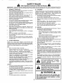
SAFETY RULES
_b
Safe Operation
Practices
for Ride-On
Mowers
&
IMPORTANT:
THIS CUTTING MACHINE IS CAPABLE OF AMPUTATING
HANDS AND FEET AND THROWING
OBJECTS
FAILURE TO OBSERVE THE FOLLOWING SAFETY INSTRUCTIONS
COULD RESULT IN SERIOUS INJURY OR DEATH
t.
•
•
•
•
•
•
°
•
•
•
•
•
•
•
•
111. CHILDREN
GENERAL
OPERATION
Read, understand, and follow aUinstructions in the manual
and on the machine before starting.
Only allow responsible adults, who are familiar with the
instructions, to operate the machine.
Clear the area of objects such as rocks, toys, wire, etc,
which could be picked up and thrown by the blade.
Be sure the area is clear of other people before mowing. Stop
machine if anyone enters the area.
Never carry passengers.
Do not mow in reverse unless absolutely necessary. Always
look down and behind before and while backing
Be aware of the mower discharge direction and do not point
it at anyone_ Do not operate the mower without either the
entire grass catcher or the guard in place.
Slow down before turning.
Never leave a running machine unattended Afways turn off
blades, set parking brake, stop engine, and remove keys
before dismounting.
Turn off blades when not mowing.
Stop engine before removing grass catcher or unclogging
chute_
Mow only in daylight or good artificial light
Do not operate the machine while under the influence of
alcohol or drugs_
Watch for traffic when operating near or crossing roadways
Use extra care when loading or unloading the machine into
a trailer or truck
Tragic accidents can occur' if the operator is not alert to the
presence of children°
Children are often attracted to the
machine and the mowing activity°
Never' assume that
children will remain where you last saw them.
•
Keep children out of the mowing area and under the watchful
care of another responsible adult
•
Be alert and turn machine off if children enter the area.r
•
Before and when backing, look behind and down for small
children
•
Never carry children. They may fall off and be seriously
injured or interfere with safe machine operation.
Never allow children to operate the machine
Use extra care when approaching blind corners, shrubs,
trees, or other objects that may obscure vision
•
•
IV.
•
SERVICE
Use extra care in handUng gasoline and other fuels They are
flammable and vapors are explosive
Use only an approved container
Never remove gas cap or add fuel with the engine
running Allow engine to cool before refueling. Do not
smoke
Never refuel the machine indoors
Never store the machine or fuel container inside where
there is an open flame, such as a water heater.
Never run a machine inside a closed area.
•
•
II.
SLOPE
Keep nuts and bolts, especially blade attachment bolts, tight
and keep equipment in good condition.
Never tamper with safety devices.
Check their proper
operation regularly_
Keep machine free of grass, leaves, or other debris build-up.
Clean oil or fuel spillage. Allow machine to cool before
storing.
Stop and inspect the equipment if you strike an object.
Repair, if necessary, before restarting.
Never make adjustments or repairs with the engine running.
Grass catcher components are subject towear, damage, and
deterioration, which could expose moving parts or allow
objects to be thrown. Frequently check components and
replace with manufacturer's recommended parts, when necessary
Mower blades are sharp and can cut Wrap the blade(s) or
wear gloves, and use extra caution when servicing them
Check brake operation frequently
Adjust and service as
required.
OPERATION
•
Slopes are a major factor related to loss-of-control
and
tipover accidents, which can result in severe injury or death.
All slopes require extra caution. If you cannot back up the
slope or if you feel uneasy on it, do not mow it.
•
=
DO:
•
Mow up and down slopes, not across.
•
Remove obstacles such as rocks, tree limbs, etco
•
Watch for holes, ruts, or bumps
Uneven terrain could
overturn the machine. Tall grass can hide obstacles.
•
Use slow speed. Choose a low gear so that you wilt not have
to stop or shift whlle on the slope.
•
Follow the manufacturer's
recommendations for wheel
weights or counterweights to improve stability
•
Use extra care with grass catchers or other attachments.
These can change the stability of the machine.
•
Keep all movement on the sfopes slowand gradual Do not
make sudden changes in speed or direction_
•
Avoid starting or stopping on a slope. If tires lose traction,
disengage the blades and proceed slowly straight down the
slope.
•
-
tant safety
precautions.
It means
Look for this BECOME
symbol to ALERT!H
point out imporCAUTIONH!
YOUR
SAFETY IS INVOLVED.
H H
DO NOT:
•
Do not turn on slopes unless necessary, and then, turn slowly
and gradually downhill, if possible.
•
Do not mow near drop-offs, ditches, or embankments. The
mower could suddenly turn over if a wheel is over the edge
of a cliff or ditch, or if an edge caves in.
•
Do not mow on wet grass. Reduced traction could cause
sliding
•
Do not try to stabilize the machine by putting your foot on the
ground
•
Do not use grass catcher on steep slopes.
&
===
i= iHi H,HHHH=
CAUTION: Always disconnect spark plug
wire and place wire where it cannot contact
spark plug in order to prevent accidental
starting when setting
up, transporting,
adjusting or making repairs,
,HHHHHH=,
• ,LWARNING A
The engine exhaust from this product contains chemicals known to the State of California to cause cancer, birth defects, or other
reproductive
harm.
2
HH=
=H=
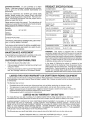
PRODUCT
CONGRATULATIONS
on your purchase of a Sears
Tractor. It has been designed, engineered and manufactured to give you the best possibte dependability and
performance.
Should you experience any problem you cannot easily
remedy, please contact your nearest Sears Authorized
Service CentedDepartment
Department. We have competent, wel!-trained technicians and the proper tools to
service or repair this tractor.
Please read and retain this manual The instructions wilt
enable you to assemble and maintain your tractor properiy
Always observe the "SAFETY RULES".
MODEL
NUMBER
917251572
SERIAL
NUMBER
SPECIFICATIONS
HORSEPOWER:
25.0
GASOLINE CAPACITY
AND TYPE:
3 5 GALLONS
UNLEADED REGULAR
OIL TYPE (APFSF/SG):
SAE 10W30 (above 32°F)
SAE 5W-30 (below 32°F)
OIL CAPACITY:
W/FILTER:
WiO FILTER:
SPARK PLUG:
GAP: .030")
CHAMPION
VALVE CLEARANCE:
NOT ADJUSTABLE
GROUND SPEED (MPH):
FORWARD:
REVERSE:
TIRE PRESSURE:
FRONT:
REAR:
BATTERY:
AMP/HR:
MIN CCA:
CASE SIZE:
CHARGING SYSTEM;
15 AMPS @ 3600 RPM
BLADE BOLT TORQUE:
30-35 FT LBS
DATEOFPURCHASE
THE MODEL AND SERIAL NUMBERS WILL BE FOUND
ON A PLATE UNDER TIdE SEAT,
YOUSHOULDRECORDBOTHSERfALNUMBERAND
DATE OFPURCHASEAND
KEEPIN A SAFE PLACE
=OR FUTURE REFERENCE.
MAINTENANCE
CUSTOMER
is available on this prodstore for details.
RESPONSIBILITIES
•
Read and observe the safety rules.
,
Foflow a regutar schedule in maintaining, caring for and
using your tractor..
,
Follow the instructions under"Customer Responsibilities" and "Storage" sections of this owner's manual
.........................
.,i
O- 5 8
0-21
14 PSI
10 PSI
40
340
UtR
In the state of California the above is required by law
(Section 4442 of the California Public Resources Code)°
Otherstates may have similar laws Federal laws apply on
federal lands. A spark arrester for the muffler is available
through your nearest Sears Authorized Service Center/
Department (See REPAIR PARTS section of this manual).,
i,._,H
LIMITED TWO YEAR WARRANTY
RC12YC
WARNING:
This tractor is equipped with an internal
combustion engine and should not be used on or near any
unimproved forest-covered, brush-covered or grass-covered land unless the engine's exhaust system is equipped
with a spark arrester meeting applicable local or state laws
(if any) If a spark arrester is used, it should be maintained
in effective working order by the operator,
AGREEMENT
A Sears Maintenance
Agreement
uct. Contact your nearest Sears
4 2 PINTS
3.7 PINTS
,,J,J,.=,,IT"H.. i=il I
ON CRAFTSMAN
,
RIDING EQUIPMENT
For two (2) years from the date of purchase, if this Craftsman Riding Equipment is maintained, lubricated and tuned up according
to the instructions in the owner's manual, Sears will i'epair or replace, free of charge, any parts found to be defective in material
or workmanship
This Warranty does not cover:
"
•
•
Expendable items which become worn during normal use, such as blades, spark plugs, air cleaners, belts, etc
Tire replacement or repair caused by punctures from outside objects, such as nails, thorns, stumps, or glass
Repairs necessary because of operator abuse, negligence, improper storage or accident or the failure to maintain the
equipment according to the instructions contained in the owner's manual
Riding equipment used for commercial or rental purposes
LIMITED 90 DAY WARRANTY
ON BATTERY
For ninety (90) days from date of purchase, if any battery included with this riding equipment proves defective in material or
workmanship and our testing determines the battery wiiFnot hotd a charge, Sears wilt replace the battery at no charge
IN-HOME WARRANTY SERVICE ON YOUR CRAFTSMAN RIDING EQUIPMENT IS AVAILABLE AT NO-CHARGE FOR 30
DAYS FROM THE DATE OF PURCHASE
PLEASE CONTACT YOUR NEAREST SERVICE CENTER. AFTER 30 DAYS
FROM THE DATE OF PURCHASE, WARRANTY SERVICE IS AVAILABLE BY TAKING YOUR CRAFTSMAN RIDING EQUIPMENT TO YOUR NEAREST SEARS SERVICE CENTER. (IN-HOME WARRANTY SERVICE WILL STILL BE AVAILABLE
AFTER 30 DAYS FROM THE DATE OF PURCHASE BUT A STANDARD TRIP CHARGE WiLL APPLY ) THIS WARRANTY
APPLIES ONLY WHILE THiS PRODUCT iS IN THE UNITED STATES
This Warranty gives you specific legal rights, and you may afso have other rights which may vary from state to state
SEARS,
..................
ROEBUCK
,,,,,
= r
AND CO., D/817 WA, HOFFMAN
,,, i
,,,n
.................
=
3
ESTATES,
= .....
tL 60179
_,_,__
TABLE OF CONTENTS
SAFETY
RULES
....................
........................................
MAINTENANCE SCHEDULE .....................................
17
SERVICE AND ADJUSTMENTS ........................... 21-27
STORAGE ...................................................................
28
TROUBLESHOOTING,
.........................................
29-30
REPAIR PARTS - TRACTOR ................................ 32-49
REPAIR PARTS - ENGINE ....................................
50-57
PARTS ORDERINGISERVIOE ............... BACK COVER
2
PRODUCT SPECIFICATIONS
......................................
3
CUSTOMER
RESPONSIBILITIES
.....................
3, 17-20
WARRANTY
..................................................................
3
TRACTOR
ACCESSORIES
..........................................
5
ASSEMBLY
.............................................................
7-10
OPERATION
..........................................................
11-16
aNDEX
A
Electrical:
Accessories....................................................
5
Interlocks and Relays ......................26
Adjustments:
Schematic ...................................... 31
Brake ......................................................
23
Wiring Diagram .............................. 32
Carburetor. .........................................27
Engine:
Clutch Pulley .......................................
23
Air Filter ........................................
20
Gauge Wheels ............................. 14
Air Screen ....................................... 19
Mower
Front-To-Back ........................ 22
Cooling Fins ................................... 20
Side-To-Side ........................... 2t
Oil Change ...................................
19
Oil Level ........................................ 15
Throttle Control Cable .................. 27
Oil Type .................................... 15,19
Air Filter, Engine ..................................... 20
Preparation ................................
15
Air Screen, Engine .....................................
18
Repair Parts .............................. 50-57
Assembly ...................................................
7-10
Starting ............................................ 15
Storage ........................................
28
Operation ...................................................
11-16
Operating Mower .................................. 14
Options:
Accessories ...................................... 5
Spark Arrester. .........................
3,40
P
Parking Brake ........................................ 13
Parts Bag .....................................................6
Parts, Replacement/Repair
........... 32-49
Product Specifications ............................. 3
R
Repair Parts ...................................... 32-49
B
Battery:
Charging ......................................... 8
Cleaning .............................................20
Starting with Weak Battery .......... 25
Storage ........................................... 28
Terminals ..................................
19
Belt:
Motion Drive
Removal/Replacement
............. 24
Mower Dd ce
Removal/Replacement
............ 22
Mower Blade Drive
Removal/Replacement
............. 23
Blade:
Sharpening ..................................
18
Replacement ................................. 18
Brake Adjustment ................................ 23
C
Carburetor Adjustment ...... .................... 27
Clutch Pulley ......................................... 23
Controls, Tractor. ................................ 12
Customer Responsibilities ............... 17-20
Engine:
Air Filter .................................
20
Air Screen .......................................19
Cooling Fins .................................20
Engine Oil ............................. 15,19
Fuel Filter .................................... 20
Spark Plug(s) ............................ 20
Tractor:
Battery ........................................ 18
Blade ...................................................
18
Lubrication Chart ....................... 17
Maintenance Schedule ............ 17
Tire Care .......................... 8,18,25
Transaxle .........................................
19
Cutting Height, Mower ..........................
!3
F
S
Filter:
Air Filter ............................................. 20
Fuel ................................................ 20
Oil ..................................................
20
Fuel:
Storage ..............................................28
Type ................................................ 15
Fuse ...................................................
26
Safety Rules ..................................................2
Seat ........................................................... 8
H
Headlights ............................................
26
Hood RemovaVInstallation .....................26
LevelingMower Deck......................... 22
Lubrication:
Chart ............................................ 17
Engine ...........................................t 9
M
.:
Service and Adjustments ............... 21-27
Carburetor ....................................... 27
Clutch Pulley ...............................
23
Fuse .....................................................26
Hood Removal/Installation ........... 26
Motion Drive Belt
Removal!Replacement
........... 22
Mower Drive Belt
Removal/Replacement
.............. 22
Mower Blade Drive Belt
Removal/Replacement
............. 23
Mower Adjustment
Front4o-Back ........................
22
Side-to-Side ...................................
21
Mower Remova!/Installation .......... 21
Tire Care
8,16,25
Slope Guide Sheet .............................. 59
Spark Plug(s) .....................................
20
Specifications ..............................
3
Starting the Engine .......................... 15-16
Steering Wheel
7,24
Stopping the Tractor ............................ 13
Storage ..................................................... 28
.......................................
Maintenance Schedule .Z:..:ii_.;; .......... 17
Mower:
Adjustment, Front-tooBack ......... 22
Adjustment, Side4mSide ............... 21
Blade Replacement ......._................. t 8
Blade Sharpening ....................... 18
T
Cutting Height ................................ 13
Throttle
Control
Cable
Adjustment ...... 27
tnstaflation ...................................... 21
Operation ....................................... 14
Tires ....................................................8,18,25
Removal
21
Troubleshooting Chart ........................29-30
Mowing Tips .........................................
16
Transaxte
19
Muffler ..................................................
20
Spark Arrester ........................... 3,40
W
.....................................
.................................
;
......
........................................................
0
Oil:
Cold Weather Conditions ........ 15,19
Engine ...........................................
19
Storage .......................................... 28
4
Warranty ..................................................
3
Wiring Diagram ...........................................
32
Wiring Schematic ................................. 31
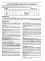
ACCESSORIES
These accessories
Most Sears stores
and attachments
can order these
AN
ATTACH
were available through most Sears retail outlets and service centers
items for you when you provide the model number of your tractor.
ENGINE
SPARK PLUG
aENTS
when the tractor
was purchased
MAINTENANCE
GAS CAN
ENGINE OIL
FUEL STABILIZER
A1R FILTER
BLADES
BELTS
,I
PERFORMANCE
Sears offers a wide variety of attachments
that fit your tractor
you. This list was current at the time of publication;
however,
may be made in these attachments,
or some may no longer
accessories
and attachments
that are available
for your
Many of these are listed below with brief explanations
of how they can help
it may change in future years - more attachments
may be added, changes
be available or fit your model
Contact
your nearest
Sears store for the
tractor_
Most of these attachments
attaching
and detaching.
or conversion
do not require
additional
hitches
AERATOR promotes deep root growth for a healthy lawn Tapered
2 5-inch steel spikes mounted on lO-inch diameter discs puncture
holes in soil at c!ose intervais to let moisture soak in Steelweight tray
for increased penetration
kits (those
that do are indicated)
and are designed
for easy
SLEEVE
CULXIVATOR
is 43 inches wide. Prepares ground for
seeding, helps weed control Steel frame holds 5 adjustable sweeps.
Adjusts vertically, horizontally
(Requires sleeve hitch)
Optional
accessory:
steel furrow opener for wider openings
for potatoes,
corn, and other deep-seeded
crops
BUMPER protects front end of tractor from damage
CARTS make hauling easy Variety of sizes available, plus accessoties such as side panel kits, tool caddy, cart cover, protective mat and
dolly.
SLEEVE HITCH for use with master lift system
uncouples
Single pin couples/
SNOWTHROWER
has 42-inch swath
Drum-type
auger handles
powdery and wet/heavy snow Mounts easily with simple pin arrangement. Discharge chute adjusts lrom tractor seat
6-inch diameter
spout discharges snow 10 to 50 feet Lift controlled at tractor seat
(Use with chains and wheel weights and/or rear drawbar weight.)
CORING AERATOR takes small plugs out of soi_ to allow moisture
and nutrients to reach grass roots 36-inchswath 24 hardened steel
coring tips 150 Ib capacity weight tray
DISC HARROW has 2 gangs of 4 sfeel blades that angle from 10 to
20 degrees, 40 inches wide Can hook 2 units in tandem. (Requires
sleeve hitch )
SPRAYERS use 12-volt DC eleclric
battery or other 12_volt source
motor that connects to the tractor
Includes booms for automatic
spraying and hand held wand for spot spraying
Wand has adiustabfe
spray pattern. For applying herbicides, insecticides,
fungicides and
liquid fertilizers
DOZER BLADE removes snow; grades dirt, sand and gravel 48
inches wide, 17 incheshigh, clears 44finch path when angled Master
lift control lever for operator ease Spring trip for snow removal on
uneven pavement; built-in float for blade to follow ground contour.
Reversible, replaceable scraper bar (Use with tire chains and wheet
weights and!or rear drawbar weight)
EASY OIL DRAIN VALVE makes oil changes easier, faster
FRONT NOSE ROLLER canters in front of mower deck to reduce
chances of "scalping" on uneven terrain
GANG HITCH lets you tow 2 or 3 pull-behind attachments at
once, such as sweepers, dethatchers, aerators (not for use with
rollers, carts or other heavy attachments)
MULCH RAKE/DETHATCHER loosens soil and flips thatch and
matted leaves to lawn surface for easy pickup. Twenty spring fine
teeth Useful to prepare bare areas for seeding. Available for front or
rear mounting. HIGH PERFORMANCE REEL-ACTION SPRING
TIN E DETHATCHER covers 36-inch wide path and tosses thatch into
large hopper Mounts behind tractor
PLOW turns soil 6 inches deep, cuts 10-inch furrow Crank adjustment controls depth, 3-posilion yoke sets width Heavy steel landside
for straight furrowing (Requires sleeve hitch.)
RAMP TOPS AND FEET let you load and unload tractor from a
pickup truck Use with 2 x 8 or 2 x 10 lumber
REAR GRADER BLADE is 42 incheswide and operated from driver's
seat Reversible steel blade can be angled at 30 degrees for grading
Reverses for pushing snow backwards (Requires sleeve hitch )
ROLLER for smoother lawn surface. 36-inch wide, 18-inch diameter
water-tight drum holds up to 390 Ibs of weight. Rounded edges
prevent harm to turf Adjustable scraper automatically cteans drum
SPREADER/SEEDERS
make seeding, fertilizing, and weed killing
easy Broadcast spreaders are also usetul for granular de-icers and
sand
SWEEPERS
let you collect
grass clippings
and teaves
TILLER has 8 hp engine to prepare seed beds, cultivate, and compost
garden residue
Chain-drivetransmission
Six11-inchdiamelerone
piece heat-treated steel tines. Tills 30-inch path (Requires sleeve
hitch ) Or use 5 hp tow-behind TILLER with 36qnch swath to prepare
seed beds, cultivate and compost garden residue. Tiller has its own
built-in lift and depth control system and does NOT require a sleeve
hilch
Fits any lawn, yard or garden tractor. Simply hook up to the
tractor drawbar and go! Optional
accessories
for 5 hp tiller convert
unit for dethatching,
aerating, hilling
without tools
TIRE CHAINS are heavy duty; closely spaced
give smooth ride, outslanding
traction
extra-large
cross links
TRACTOR CAB has heavy duty vinyl fabric over tubular steel frame,
ABS plastic top; clear plastic windshield offers 360 degree visibility
Hinged metal doors with catch
Keeps operator warm and dry
Remove vinyl sides and windshields
for use as sun protector in
summer.
Optional
accessories
include:
tinted/tempered
solid
safety glass windshield with hand operated wiper; 12-volt amber
caution Hght for mounting on cab top
VACS for powerful collection of heavy grass clippings and leaves
Optional wand attachment
to pick up debris in hard-to-reach
places
VAC/CHIPPER
includes a chipper-shredder
WEIGHT BRACKET for drawbar for snow removal applications.
Can
be mounted on front of fractor for plowing applications
Uses (1) 55
Ib weight
WHEEL
removal
5
WEIGHTS for rear wheels
or dozing heavy materials
provide
needed
traction
for snow
u H
i
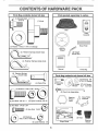
CONTENTS
L
OF HARDWARE
PACK
i
Parts Bag contents
shown full size
(1) Shoulder Bolt
5/16-18
Parts packed separately
in carton
(1) Knob
Seat
Video
Cassette
|
(1) Washer
17/32 x 1-3/t6 x 12 Gauge
Steering
Wheel
ner Springs (single loop)
i --
Manual
(4) Retainer Springs
=r-q
Parts bag contents not shown full size
=
_
,
/f-_\,
Bolts
\
\_
_
(2)Washers
3/8
_.//y(2)
Gauge z_.
Wheels
_
(2) Centerlock Nuts
(2) Washers 17/32 x 7/8 x 16 Ga,
@
(2) Hex Bolts 3/8-16 x t
Front Link Assemblies
Steering
Wheel
insert
(2) Nylon Locknuts 3/8-16
(2) Hex Bolts 1/4-20 x 3/4
(2) Hex Nuts t/4-20
•
_(2)
:_
Nose Roller
Brackets
@
9/32 x 5/8 x 16 Gauge
(2) Washers
(2) Lock Washers
(2) Keys
Slope Sheet
1/4
,,,,d
6
Steering
Sleeve
i .....
i
., Hi ,,
N _1 II
ASS
LY
Your new tractor has been assembled at the factory with the exception of those parts left unassembled for shipping purposes.
To ensure safe and proper operation of your tractor all parts and hardware you assemble must be tightened securely.. Use
the correct tools as necessary to insure proper tightness.
TOOLS REQUIRED
FOR ASSEIVlBLY
A socket wrench set will make assembly easier. Standard
wrench sizes are listed.
(2) 7/16" wrenches
Tire pressure gauge
(1) 1/2" wrench
Utility knife
(2) 9/16" wrenches
(1) 3/4" wrench
(1) 3/4" socket with drive ratchet
When right or left hand is mentioned in this manual, it
means when you are in the operating position (seated
behind the steering wheel)_
TO REMOVE TRACTOR
UNPACK
FROM CARTON
CARTON
o
Remove all accessible loose parts and parts cartons
from carton (See page 6).
o
Cut, from top to bottom, along lines on all four comers
of carton, and lay panels flaL
,
Check for any additional loose parts or cartons and
remove.
BEFORE ROLLING TRACTOR
ATTACH
STEERING
WHEEL
OFF SKID
(See Fig. 1)
-
Remove hex bolt, lock washer and large flat washer
from steering shafL
o
Position front wheels of the tractor so they are pointing
straight forward,
o
Slide the steering sleeve over the steering shafl_
°
Position steering wheel so cross bars are horizontal
(left to right) and slide onto steering wheel adapter.
*
o
FIG, 1
TO ROLL TRACTOR
OFF SKID (See Operation section for location and function
of controls)
=
Secure steering wheel to steering shaft with hex bolt,
lock washer and large flat washer previously removed.
Tighten securely.
Press lift lever plunger and raise attachment lift lever to
its highest position.
=
Release parking brake by depressing
pedal
Snap steering wheel insert into center of steering
wheel
"
o
disengageP'ace
freewheeltransmissionC°ntr°l
i_fre,,_w_leTeRli_l_lPl_tl_°_, tin°
the Operation section of this manual).
Roll tractor forward off skid.
.
•
Remove mower and packing materials.
Remove ties from V-belts.
o
Remove protective plastic from tractor hood and grill
IMPORTANT: CHECK FOR AND REMOVEANY STAPLES
IN SKID THAT MAY PUNCTURE TIRES WHERE TRACTOR
IS TO ROLL OFF SKID.
clutch/brake
i
Ul
, ,
, ii ,i ,,
, i i,,i
i,,i u,
,
ii i,ii ,,,lUl
ii, ,lllllllll,lllllll
LY
H_
CONNECT
BATTERY
INSTALL SEAT (See Fig. 3)
(See Fig. 2)
Adjust seat before tightening adjustment knob.
•
Place seat on seat pan and assemble shoulder bolt.
=
Positive terminal must be connected
first to prevent sparking from accidental grounding.
Assemble adjustment
Do not tighten,
°
Tighten shoulder bolt securely,
•
Lower seat into operating position and sit on seat°
•
Sfide seat until a comfortable position is reached which
allows you to press clutch/brake pedat all the way
down.
.
Get off seat without moving its adjusted position.
•
Raise seat and tighten adjustment knob securely,
•
Lift hood to raised position,
o
Open terminal access doors, remove terminal protective caps and discard,
=
If this battery is put into service after month and year
indicated on label (label located between terminals)
charge battery for minimum of one hour at 6-t0 amps.
=
First connect RED battery cable to positive (+) battery
terminal with hex bolt, flat washer, lock washer and hex
nut as shown Tighten securely
o
Connect BLACK grounding cable to negative (-) battery terminal with remaining hex bolt, fiat washer, lock
washer and hex nut° Tighten securely.
Close terminal access doors,,
°
Remove cardboard packing on seat pan,
nals. Before connecting battery, remove metalDo bracelets,
wristwatch
CAUTION:
not short battery
termibands, rings, etc_
knob and fiat washer loosely,,
SEAT
SHOULDER
_
_\ \r'T"'_
\'
\\ \
Use terminal access doors for:
o
Inspection for secure connections
ware).
-
Inspection for corrosion.
-
Testing battery,,
•
Jumping (if required)_
(to tighten hard-
ADJUSTMENT
KNOB
FIG. 3
Periodic charging,
HEX NUT
LOCK
WASHER
FLAT
WASHER
DISCARD TERMINAL
_ROTECTIVE CAPS
HEX,"
BOLT
TO ATTACH
•
•
POSITIVE
(RED)
CABLE
NOSE ROLLER
(See Fig. 4)
Position brackets, 17/32 x 7/8 x 16 gauge washers, and
nose rolter between deck mounting brackets as shown.
Be sure to position brackets on correct side, as shown°
Install 3/8-16 x 1 hex bolts and 3/8-16 crownlock nuts
as shown_ Tighten hardware securely.
NOTE: Be sure bracket tabs are positioned in tab holes in
deck brackets.
"B"BRACKETTAB
,I
NEGATIVE
(BLACK)
CABLE
FIG. 2
HEX
"A"
BRACKET
CROWNLOCK
NUT
TAB
WASHER
FIG. 4
,,n,=,
H,
,
i=,===
......
i .........
,,H,
=,==,'"==
ASS
....,,
INSTALL
,,, ,nu,,,
MOWER
= ,
,,, n,,u,i
,r,,,,i
1,
AND DRIVE BELT
..........
,,
nu, n
,
=
LY
,,,
,,r,r,,,
°
,u
,,,,,
.........................
Connect anti-sway bar to chassis bracket under left
footrest and retain with double loop retainer spring°
Turn height adjustment knob clockwise to remove
slack from mower suspension,
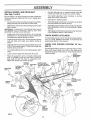
(See Figs. 5 and 6)
Be sure tractor is on level surface and mower suspension
arms are raised with attachment lift control, Engage parking brake.
°
°
Raise deck to highest position,
•
Cut and remove ties securing anti-sway bar and belts°
Swing anti-sway bar to left side of mower deck,
°
Assemble gauge wheel bars to brackets using clevis
pins and double loop retainer springs
o
Slide mower under tractor with discharge guard to right
side of tractor,.
°
IMPORTANT: CHECK BELT FOR PROPER ROUTING IN
ALL MOWER PULLEY GROOVES. INSTALL BELT INTO
ELECTRIC CLUTCH PULLEY GROOVE
Assemble gauge wheels as shown using long shoulder
bolts, 3/8 washers, and 3/8-16 center locknuts. Tighten
securely,
-
Adjust gauge wheels before operating mower as shown
in the Operation section of this manual.
°
Install one front link in top hole of the L,H. front mower
bracket and L.H front suspension bracket., Retain with
two single loop retainer springs as shown.
,
Install second front link in RH front suspension bracket
only and retain with single loop retainer spring as
shown
,,
Slide right side of mower back and install link in top hole
of R,H. front mower brackeL Retain with single loop
retainer spring as shown_
-
Turn height adjustment knob counterclockwise
stops,,
•
Lower mower linkage with attachment lift control
.
Place the suspension arms on inward pointing deck
pins° If necessary, rock and raise front of mower to
align deck pins with the holes in suspension arms,
Retain with double loop retainer springs
CHASSIS
BRAC ET ANTI-SWAY
DOUBLE LOOP
RETAINER
SPRING
SHOULDER
BOLT
BAR
until it
CHECK
LEVELNESS
For best cutting results, mower should be properly leveled.
See "TO LEVEL MOWER HOUSING" in the Service and
Adjustments section of this manual°
CHECK
BELTS
FOR
PROPER
POSITION
OF
ALL
See the figures that are shown for replacing motion, mower
drive, and mower blade drive belts in the Service and
Adjustments section of this manual, Verifythat the belts are
routed correctly
FRONT
SUSPENSION
BRACKETS
DOUBLE LOOP
RETAINER SPRING
(inward
pins)
MOWER
pointing
FRONT
LINKS
SUSPENSION
ARMS
ELECTRIC
CLUTCH
PULLEY
deck
Loll, GAUGE
WHEEL BAR
!
SINGLE
LOOP RETAINER
SPRINGS
GAUGE
WHEEL
318
WASHER
FRONT
MOWER
BRACKET
3t8-16
CENTER
LOCKNUT
DISCHARGE
GUARD
CLEVIS
PINS
IDLER
LOOP
RETAINER
SPRINGS
FIG. 5
BLY
i
CHECK
i
/CHECKLIST
TIRE PRESSURE
The tires on your tractor were ovednflated at the factory for
shipping purposes_ Correct tire pressure is important for
best cutting performance.
•
BEFORE YOU OPERATE AND ENJOY YOUR NEW
TRACTOR, WE WISH TO ASSURE THAT YOU RECEIVE
THE BEST PERFORMANCE AND SA TISFA CTION FROM
THIS QUALITY PRODUCT
Reduce tire pressure to PSI shown in "PRODUCT
SPECIFICATIONS" on page 3 of this manual
CHECK
BRAKE
PLEASE REVIEW THE FOLLOWING
SYSTEM
After you learn how to operate your tractor, check to see
that the brake is properly adjusted. See "TO ADJUST
BRAKE" in the Service and Adjustments section of this
manual°
CHECKLIST:
_"
All assembly instructions have been completed..
v"
No remaining loose parts in carton.
,/
Battery is properly prepared and charged.
1 hour at 6 amps)..
,/
Seat is adjusted comfortably and tightened securely.
,/
NI tires are properly inflated. (For shipping purposes,
the tires were overinflated at the factory).
#'
Be sure mower deck is propedy leveled side-to-side/
front-to-rear for best cutting results. (Tires must be
properly inflated for leveling)..
,/
Check mower and drive belts. Be sure they are routed
properly around pulleys and inside all belt keepers.
,/
Check wiring. See that all connections are still secure
and wires are properly clamped°
,/
Before driving tractor, be sure freewheel control is in
drive position°
(Minimum
WHILE LEARNING HOW TO USE YOUR TRACTOR, PAY
EXTRA ATTENTION TO THE FOLLOWING IMPORTANT
ITEMS:
•/
Engine oil is at proper level
,/
Fuel tank is filled with fresh, clean, regular unleaded
gasoline.
Become familiar with all controls - their location and
function. Operate them before you start the engine..
,/
10
J
Be sure brake system is in safe operating condition.
,/
tt is important to purge the transmission before operat..
ing your tractor for the first time. Follow proper starting
and transmission purging instructions (See"TO START
ENGINE" and 'PURGE TRANSMISSION
in the Operation section of this manual).
.........
ii1,,11,,,iu
i
irlr i .....................................
OPERATUON
........
....
n fill
I'
Ull ...................
nll,i
iiii1,111
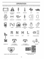
These symbols may appear on your tractor or in literature supplied with the product. Learn and understand their meaning,
BATTERY
CAUTION OR
WARNING
REVERSE
FORWARD
FAST
SLOW
ENGINE ON
ENGINE OFF
OILPRESSURE
CLUTCH
LIGHTS ON
LIGHTS OFF
FUEL
CHOKE
DIFFERENTIAL
LOCK
PARKING BRAKE
LOCKED
UNLOCKED
REVERSE
MOWER LIFT
MOWER HEIGHT
NEUTRAL
ATTACHMENT
CLUTCH ENGAGED
HIGH
LOW
PARKING BRAKE
ATTACHMENT
CLUTCH DISENGAGED
HYDROSTATIC
DANGER, KEEP HANDS AND FEET AWAY
IGNITION
FREE WHEEL
(Hydro Models only)
1I
..........................
ii
.
i.
i,
i.i
.i i..11..==1==..!
..
.r.
I ' ' H',HI
OPERATION
ii
iiiiiii
.I.IIIII,H,I,I,
i...,HI
iii1.,i.iiHm,
ii ii ,i
.111
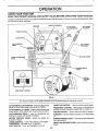
KNOW YOUR TRACTOR
READ THIS OWNER'S
MANUAL
AND SAFETY
RULES BEFORE
OPERATING
YOUR TRACTOR.
Compale the illustratfonswith you r tractor to familiarize yourself with the location of Various controls and adjustments° Save
this manual for future reference_
THROTTLE
CONTROL
AMMETER
ATTACHMENT
CLUTCH SWITCH
LIFT LEVER
.UNGER
CHOKECONTROL
HOUR
METER
LIGHT SWITCH
CLUTCHtBRAKE
PEDAL
ATTACHMENT
LIFT LEVER
IGNITION SWITCH
HEIGHTADJUSTMENT
KNOB
PARKING
LEVER
BRAKE
MOTION
CONTROL
LEVER
SPEEDS:
/
FREE WHEEL CONTROL
FIG. 6
Our tractors conform to the safety standards of the American National Standards Institute,
THROTTLE
ATTACHMENT CLUTCH SWITCH- Used to engage mower
blades or other attachments mounted to your tractor°
FREEWHEEL CONTROL - Disengages transmission for
pushing or slowly towing the tractor with the engine off,,
ATTACHMENT LIFT LEVER - Used to raise and lower the
mower' deck or other attachments mounted to your tractor_
CLUTCHIBRAKE
PEDAL - Used for declutching
braking the tractor and starting the engine.,
CONTROL _ Used to control engine speed,
IGNITION SWITCH - Used to start and stop the engine°
and
AMMETER -Indicates battery charging (+) or discharging
(-).
PARKING BRAKE LEVER - Locks clutch/bi"ake pedal into
the brake position_
MOTION CONTROL LEVER - Selects the speed and
direction of tractor.
CHOKE CONTROL - Used when starting a cold engine,
HOURMETER - Indicates hours of operation.
LIGHT SWITCH - Turns the headlights on and off°
HEIGHT ADJUSTMENT KNOB _Used to adjust the mower
height°
12
OPERATION
i
............
,,m,=
.
The operation of any tractor can result in foreign objects thrown into the eyes, which can result
in severe eye damage. Always wear safety glasses or eye shields while operating your tractor
or performing any adjustments or repairs. We recommend a wide vision safety mask over the
spectacles or standard safety glasses.
,=,N,,,=
,,,,,,,
='==
......
.,,,,,.............
HOW TO USE YOUR TRACTOR
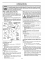
TO SET PARKING
BRAKE
NOTE: Under certain conditions when unit is standing idle
with the engine running, hot engine exhaust gases may
cause "browning" of grass. To eliminate this possibility,
always stop engine when stopping tractor on grass areas.
(See Fig. 7)
Your tractor is equipped with an operator presence sensing
switch. When engine is running, any attempt by the
operator to leave the seat without first setting the parking
brake will shut off the engine.
=
Depress clutch/brake pedal into full "BRAKE" position
and hold.
•
_stop
_ _
PUSH IN TO
ATTACHMENT
tractor comletp ely, as described above, before leav-
J _ ,_o_rator_
_cher_
Place parking brake tever in "ENGAGED" position and
release pressure from clutch/brake pedal.. Pedal should
remain in "BRAKE" position_ Make sure parking brake
witl hold tractor secure.
THROTTLE
"DISENGAGE"
CONTROL LEVER
.........
position; to empty
etc_
TO USE CHOKE
CONTROL
(See Fig. 7)
Use choke control whenever you are starting a cold engine.
Do not use to start a warm engine
°
To engage choke control, pull knob ouL Slowly push
knob in to disengage
CLUTCH
SWITCH PULL OUT TO
"ENGAGE'
TO USE THROTTLE
CHOKE
CONTROL
(See Fig, 7)
Always operate engine at full throttle.
,
Operating engine at less than full throttle reduces the
battery charging rate
Full throttle offers the best bagging and mower performance
CONTROL
CLUTCH/BRAKE
PEDAL"BRAKE"
POSITION
TO iVlOVE FORWARD
(See Fig. 7)
IGNITION
AND BACKWARD
The direction and speed of movement is controlled by the
motion control [ever.
MOTION
CONTROL
LEVER
"DRIVE"
POSITION
HEIGHT
ADJUSTMENT
KNOB
"DISENGAGED
POSITION
....
PARKING
BRAKE
ENGAGED"
POSITION
clutch switch to "DISENGAGED"
Release parking brake and clutch/brake
°
Slowly move motion control lever to desired position.
NOTE: Failure to move throttle control to slow (,_)
position and allowing engine to idle before stopping may
cause engine to "backfire".
Turn ignition key to "OFF" position and remove key.
Always remove key when leaving tractor to prevent
unauthorized use
o
Never use choke to stop engine
CUTTING
HEIGHT
(See
°
Turn knob clockwise (f"_) to raise cutting height.
,
Turn knob counterclockwise
height
(V_,)to
tower cutting
°
The average lawn should be cut to approximately 2-1/2
inches during the cool season and to over 3 inches
during hot months For healthier and better looking
lawns, mow often and after moderate growth
°
For best cutting performance, grass over 6 inches in
height should be mowed twice. Make the first cut
relatively high; the second to desired height.
Move throttle control to slow (,,_.) position
,
MOWER
pedal
The cutting height range is approximately 1-1/2" to 4-1/2".
The heights are measured from the ground to the blade tip
with the engine not running.. These heights are approximate and may vary depending upon soil conditions, height
of grass and types of grass being mowed..
•
Depress clutch/brake pedal into full "BRAKE" position
o
Move motion control lever to neutral (N) position.
IMPORTANT:
THE MOTION CONTROL LEVER DOES
NOT RETURN TO NEUTRAL (N) POSITION WHEN THE
CLUTCH/BRAKE PEDAL IS DEPRESSED.
ENGINE =
•
The cutting height is controlled by turning the height adjustment knob in desired direction°
(See Fig. 7)
MOWER BLADES
°
Move attachment
position_
GROUND DRIVE -
Start tractor with motion control lever in neutral (N)
position..
TO ADJUST
Fig. 7)
FIG. 7
STOPPING
°
13
Hm,
=1=
OPERATION
i
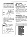
TO OPERATE
TO ADJUST GAUGE WHEELS (See Fig, 8)
Adjust gauge wheels with tractor on a fiat level surface_
=
Adjust mower to desired cutting height,
°
Lower mower with tift control. Remove rear retainer
spring and clevis pin which secure each gauge wheel.
o
Lower gauge wheels to ground° Raise gauge wheels
slightly to align holes in bracket and gauge wheel bar
and insertclevis pins. Gauge wheels should be slightly
off the ground
'
.
_rive--_p
i
!
ON HILLS
or'down
hills with slopes greater than 15 ° and
do not drive across _any slope.
i
I
I
o
Choose the slowest speed before starting up or down
hills.
o
•
Avoid stopping or changing speed on hills.
If slowing is necessary, move tt]rottte control lever' to
slower position.
If stopping is absolutely necessary, push clutch/brake
_edal quickly to brake position and engage parking
rake_
Replace retainer springs into clevis pins.
°
RETAINER
SPRING
.
Move motion control lever to neutral (N) position.
IMPORTANT:
THE MOTION CONTROL LEVER DOES
NOT RETURN TO NEUTRAL (N) POSITION WHEN THE
CLUTCH/BRAKE PEDAL IS DEPRESSED.
•
To restart movement, slowly release parking brake and
clutch/brake pedal
.
Slowly move motion control lever to slowest setting.
.
Make all turns slowly
GAUGE
WHEEL BAR
GAUGE
WHEEL'
TO TRANSPORT
BRACKET
FIG. 8)
TO OPERATE
MOWER
(See Figs. 6 and 7)
Your tractor is equipped with an operator' presence sensing switch. Any attempt by the operator to leave the seat
with the engine running and the attachment clutch engaged
will shut off the engine.
•
Select desired height of cut.
Lower mower' with attachment lift control.
°
Start mower blades by engaging attachment clutch
control.
.
TO STOP MOWER BLADES- disengage attachment
clutch control.
CAUTION: Do not operate the mower
without either the entire grass catcher_
on mowers so equipped, or the discharge guard in place.
"'
(See Figs, 6 and 10)
When pushing or towing your tractor, be sure to disengage
transmission by placing freewheel control in freewheeling
position. Free wheel control is located at the rear drawbar
of tractor°
I
i
°
Raise attachment lift to highest position with attachment lift control.
.
Remove retainer spring from freewheel control rod.
o
Push control rod in to disengage transmission and
reinsert retainer spring into control rod hole now on
back side of the bracket
,
Do not push or tow tractor at more than two (2) MPH.
-
To reengage transmission, reverse above procedure.
NOTE: To protect hood from damage when transporting
you r tractor on a truck or a traile r, be su re hood is closed and
secured to tractor:. Use an appropriate means of tying hood
to tractor (rope, cord, etc.).
RUNNER
"DISCHARGE
GUARD
FIG, 9
14
FIG. 10
•
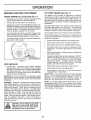
The engine in your tractor has been shipped, from the
factory, already filled with summer weight oil
•
Check engine oil with tractor on level ground_
This engine on this product is designed for maximum
performance and life if operated with the choke (l\l) fully
open and the throttle control in the fast (,_) position. To
open the choke fully requires an engine warm-up period of
several seconds to several minutes, depending on the
temperature°
•
Unthread and remove oil fill cap/dipstick; wipe oil off
Reinsert the dipstick into the tube and rest oil fill cap on
the tube. Do not thread the cap onto the tube. Remove
and read oil level If necessary, add oil until "FULL"
mark on dipstick is reached. Do not overfill.
After starting the engine, first open the choke slowly until
the engine just begins to run smoothly.. Then open the
choke in smal_ steps, allowing the engine to accept sma}i
changes in speed and load, until the choke is fully open..
=
For cold weather operation you should change oil for
easier starting (See "OIL V_SCOSITY CHART' in the
Customer Responsibilities section of this manual)
CHECK
,
ENGINE
OIL LEVEL (See Fig. 11)
During engine warm-up, the equipment can be operated
When starting engine for the first time or if engine has run
out of fuel, it will take extra cranking time to move fuel from
the tank to the engine.
To change engine oil, see the Customer Responsibilities section in this manual,
•
Depress clutch/brake pedal and set parking brake.r
•
Place motion control lever in neutral (N) position.
•
Move attachment clutch to "DISENGAGED"
•
Pull choke control out to choke (N) position for cold
engine start. For warm engine start do not use choke
control
o
Move throttle control to midway between fast (,_) and
slow (,_) positions
o
Insert key into ignition and turn keyctockwiseto"START"
position and release key as soon as engine starts. Do
not run starter continuously for more than fifteen
seconds per minute, tf engine does not start after
several attempts, move throttle control to fast (,_)
position, wait a few minutes and try again.
°
When engine starts, slowly push choke control in..
FIG. 11
ADD GASOLINE
•
Fil! fuel tank. Use fresh, clean, regular unleaded
gasoline with a minimum of 87 octane.. (Use of leaded
gasoline will increase carbon and lead oxide deposits
and reduce valve rife). Do not mix oil with gasoline.
Purchase fuel in quantities that can be used within 30
days to assure fuel freshness
IMPORTANT: WHEN OPERATING tN TEMPERATURES
BELOW 32°F(0°C), USE FRESH, CLEAN WINTER GRADE
GASOLINE TO HELP INSURE GOOD COLD WEATHER
STARTING.
!_
iH,,
filler neck. Do not overfill, Wipe off any
spilled oil or fuel, Do not store, spill or
CALITION:
to bottom
gas tank
use gasoline Fill
near
an open of
flame.
Hi
Move throttle control to fast (,_) position_
o
Mow engine to warm up for a few minutes before
engaging drive or attachments
NOTE: If at a high altitude (above 3000 feet) or in cold
temperatures (below 32°F), the carburetor fuel mixture
may need to be adjusted for best engine performance.. See
"TO ADJUST CARBURETOR" in the Service and Adjustments section of this manual
H
............................................
°
IMPORTANT: COLD STARTING FOR HYDRO (BELOW
40°F) - AFTER STARTING ENGINE AND BEFORE
DRIVING, LET TRANSMISSION
WARM UP FOR (1)
MINUTE BY PLACING MOTION CONTROL LEVER IN
NEUTRAL AND RELEASING CLUTCH/BRAKE PEDAL
WARNING:
Experience indicates that alcohol blended
fuels (called gasohol or using ethanol or methanol) can
attract moisture which leads to separation and formation of
acids during storage
Acidic gas can damage the fuel
system of an engfne while in storage
To avoid engine
problems, the fuel system should be emptied before storage of 30 days or longer. Drain the gas tank, start the
engine and let it run until the fuel lines and carburetor are
empty. Use fresh fuel next season. See Storage Instructions for additional information
Never use engine or
carburetor cleaner products in the fuel tank or permanent
damage may occur.
MI,,
position..
I,H,
15
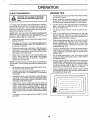
MOWING TiPS
PURGE TRANSMISSION
t ,H= =
I
_
'H'H"'H'=
=
I ' I I='1=
' I' I' '11",11"
freewheel lever while the engine is runCAUTION: Never engage or disengage
ning,
To ensure proper operation and pedormance, it is recommended that the transmission be purged before operating
tractor for the first time. This procedure will remove any
trapped air inside the transmission which may have developed during shipping of your tractor.
IMPORTANT: SHOULD YOUR TRANSMISSION REQUIRE
REMOVAL FOR SERVICE OR REPLACEMENT,
IT
SHOULD BE PURGED AFTER REINSTALLATION
BEFORE OPERATING THE TRACTOR.
o
•
Tire chains cannot be used when the mower housing
is attached to tractor
o
Mower should be properly leveled for best mowing
performance. See "TO LEVEL MOWER HOUSING" in
the Service and Adjustments section of this manual
•
Use the runner on the right hand side of mower as a
guide. The blade cuts approximately an inch outside
the runner (See Fig 9).
The left hand side of mower should be used for' trimming.
=
Place tractor safely on level surface with engine off and
parking brake set,
Disengage transmission by placing freewheel control
in freewheeling position (See "TO TRANSPORT" in
this section of manual).
o
Drive so that clippings are discharged onto the area
that has been cut Have the cut area to the right of the
tractor. This wilt result in a more even distribution of
clippings and more uniform cutting
-
When mowing large areas, start by turning to the right
so that clippings will discharge away from shrubs,
fences, driveways, etc. After one or two rounds, mow
in the opposite direction making left hand turns until
finished (See Fig_ 12 )o
,
Sitting in the tractor seat, start engine_ After the engine
is running, move throttle control to slow (,_) position_
With motion control lever in neutral (N) position, slowly
disenqage clutch/brake pedal.
o
If grass is extremely tail, it should be mowed twice to
reduce load and possible fire hazard from dried clip*
pings. Make first cut relatively high; the second to the
desired height.
=
Move motion control lever to full forward position and
hold for' five (5) seconds. Move lever to full reverse
position and hold for five (5) seconds. Repeat this
procedure three (3) times.
•
Do not mow grass when it is wet. Wet grass will plug
mower' and leave undesirable clumps. Allow grass to
dry before mowing.
°
Always operate engine at full throttle when mowing to
assure better mowing performance and proper discharge of material Regulate ground speed by selecting a low enough gear to give the mower cutting
performance as well as the quality of cut desired
°
When operating attachrnents, select a ground speed
that will suit the terrain and give best performance of
the attachment being used.
NOTE: During this procedure there will be no movement of
drive wheels _The air is being removed from hyd raulic drive
system
•
Move motion control lever to neutral (N) position. Shutoff engine and set parking brake.
,
Engage transmission by placing freewheel control in
driving position (See "TO TRANSPORT" in this section
of manual).
•
Sitting inthetractor seat, start engine. After the engine
is running move throttle control to half (1/2) speed.
With mot on contro lever in neutral (N) position, slowly
disengage clutch/brake pedal.
•
Slowly move motion control lever forward, after the
tractor moves approximately five (5) feet, slowly move
motion control lever to reverse position, After the
tractor moves approximately five(5) feet return the
motion control lever to the neutral (N) position. Repeat
this procedure with the motion control lever three (3)
times.
°
F
C
Your tractor is now purged and now ready for normal
operation_
FIG, 12
16
i,
i,UlUllll
,i,ii
ilU
CUSTOMER
iil,lrll
..........................................
I iiii
RESPONSIBUUTIES
........................
i i
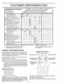
"MAINTENANCE
SCHEDULE
i ii,ll ii
/__.-__o__
FtLL iN DATES
....................
/__,_/_+
_"_
REGULAR
SERvlcE ..........
T
R
ATES
Check
Brake
6/
_#'
Check
Tire Pressure
Operation
6/
6/
Check
for Loose
6/
Fasteners
"Shar;en/Replace
'Lubrication
Mower
!
--_
--_6/7
Blades
Chart
t
6/
I
1
Check
Battery
Level/Recharge
0
Clean
Battery
and Terminals
6/
a
CheckTransaxie
Cooling
6/
Blade
Adjust
Motion
Diive
Check
Engine
Oil Level
Change
Belt(s) Tension
Engine
Clean
Air Filter
N
Clean
Air Screen
G
inspect
I
6/
6/'4
T
Adjust
Beit(s)
Tension
6/5
"6# 4
'
' 6/
6/
.....
....
'
6/
6/
_,2
Fins
Air Filter Paper
Replace
Fuel Filter
Cartridge
_
_
L
i 6/2
6#4
.................................
__
j
6/
!
, ,,
5 - g equipped wi_hadjustable system
6 - No] requi[ed i:[equipped with maintenance4ree battery
7 +Tighten {runtaxle pivot boil to 35 I1-_bs maximum
Do not overtighten
RECOMMENDATIONS
LUBRICATION
(_)TIE
(_)SPINDLEZERK
Some adjustments will need to be made periodically to
properly maintain your tractor°
f,q
i___,-,,
/
\
"_
_:_:.,:'_
®STEER,NG
Once a year you should replace the spark plug, clean
or replace air filter, and check blades and belts for
wear.. A new spark plug and clean air filter assure
proper air-fuel mixture and help your engine run better
and last longer.
CHART
ROD BALL JOINTS
(_) FRONT WHEEL "__.
All adjustments in the Service and Adjustments section of
this manual should be checked at least once each season.
BEFORE
..............
6/2
The warranty on this tractor does not cover items that have
been subjected to operator abuse or negligence,. To
receive full value from the warranty, operator must maintain
tractor as instructed in this manual..
,
J
i
6/
!
1 - Change mare allen when operating under a heavy load er in high ambien_temperalures
2 - Sen'ice more oflen when opmaling in dirly or dusty conditions
3 + I[ equipped with oil {flier,change oi_ever,/50 hours
4 + Replace b_adesmore ellen when mowing in sandy soil
GENERAL
_===
....
Arrester
Replace
...............
"......
_1,2,3
Replace Oil Filter(ifequipped)
Clean Engine Cooling
Replace Spark Ptug
6/
6#15
Oil
Muffler/Spark
, i i,iii
SPtNDLEZERK(_)
FRONT WHEEL(_
?1%'
SECTOR GEAR
TEETH
ENGINE (_)
EACH USE
•
Check engine oil level
o
Check brake operation.
,
,
Check tire pressure
Check for loose fasteners.
(_) SPRAY SILICONE
IMPORTANT:
DO NOT OIL OR GREASE THE PIVOT POINTS
WHfCH HAVE SPECIAL NYLON BEARINGS
VISCOUS LUBRiCANTS W+LL ATTRACT
DUST AND DIRT THAT WILL SHORTEN
THE LiFE OF THE SELF-LUBRICATING
BEARINGS.
iF YOU
FEEL THEY MUST BE LUBRICATED,
USE ONLY A DRY, POWDERED GRAPHITE
TYPE LUBRICANT
SPARINGLY
(_) GENERAL
®
17
LUBRICANT
PURPOSE
(MOVE BOOTS TO LUBRICATE)
GREASE
REFER TO CUSTOMER
RESPONSIBILITIES
ENGINE
SECTION
.....................
CUSTOMER
ii,
ii
,nnll ¸
I"
i
RESPONSlBILITI
n ilnl,n nlnnl
TRACTOR
TO SHARPEN
Always observe safety rules when performing any maintenance.
Care should be taken to keep the blade balanced. An
unbalanced btade will cause excessive vibration and eventual damage to mower and engine_
BRAKE
OPERATION
BLADE (See Fig. 14)
•
If tractor requhes more than six (6) feet stopping distance
at high speed in highest gear, then brake must be adjusted.
(See "TO ADJUST BRAKE" in the Service and Adjustments section of this manual).
The blade can be sharpened with a file or on a grinding
wheel Do not attempt to sharpen while on the mower.
.
To check blade balance, you will need a 5/8" diameter
steel bolt, pin, ora cone balancer. (When using a cone
balancer, follow the instructions supplied with balancer).
TIRES
,
Stide blade on to an unth readed portion of the steel bolt
or pin and hold the bolt or pin parallel with the ground.
If blade is balanced, it should remain in a horizontal
position. If either end of the blade moves downward,
sharpen the heavy end until the blade is balanced.
o
Maintain proper air pressure in all tires (See "PROD' manu al ).
UCT SPECIFICATIONS " on page 3 of this
,
Keep tires free of gasoline, oil, or insect control chemicals which can harm rubber.
*
Avoid stumps stones, deep ruts, sharp objects and
other hazards that may cause t re damage.
BLADE
NOTE: Do not use a nai! for balancing blade. The lobes of
the center hole may appear to be centered, but are not.
CENTER
CARE
HOLE
For best results mower blades must be kept sharp_ Replace bent or damaged blade&
BLADE
REMOVAL
(See Fig. 13)
7
/
5t8" BOLT
,
Raise mower to highest position to allow access to
bfades_
,
Remove hex bolt, lock washer and flat washer securing
blade.
,
Install new or resharpened blade with trailing edge up
towards deck as shown.
,
Reassemble hex bolt, lock washer and flat washer in
exact order as shown.
/
/
J
BLADE
FIG, 14
BATTERY
,
Tighten bolt securely (30-35 Ft. Lbs. torque).
IMPORTANT: BLADE BOLT IS GRADE 8 HEATTREATED.
Your tractor has a battery charging system which is sufficient for normal use. However, periodic charging of the
battery with an automotive charger will extend its life.
NOTE: We do not recommend sharpening blade- but if you
do, be sure the blade is balanced.
MANDREL
BLADE
_L_,_
_ ASSEMBLY
.
Keep battery and terminals clean
•
Keep battery bolts tight.
.
Keep small vent holes open°
•
Recharge at 6-10 amperes for 1 hour_
TO CLEAN BATTERY AND TERMINALS
Corrosion and dirt on the battery and terminals can cause
the battery to "leak" power.
FLAT WASHER _._,
LOCK WASHER _
_%_I
____
/
/
Remove terminal guard,,
•
Disconnect BLACK battery cable first then RED battery cable and remove battery from tractor°
Rinse the battery with plain water' and dry°
.
HEX BOLT (GRADE 8) _
•AGRADE
8HEAT
TREATED
BOLT
CANBE
IDENTIFIED
•
•
Clean terminals and battery cable ends with wire brush
until bright.
•
Coat terminals with grease or petroleum jelly.
o
Reinstall battery (See "CONNECT
Assembly section of this manual).
BY SiX LINES ON THE BOLT HEAD,
FIG. 13
18
BATTERY" in the
,,Ulll
n lU U,l,,,nul i
CUSTOMER
.............
ulll,
TRANSAXLE
ii,
RESPONS BUL
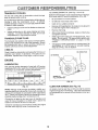
TO CHANGE ENGINE OIL (See Figs, 15 and 16)
COOLING
The fan and cooting fins of transmission
c{ean to assure proper cooling.
Determine temperature range expected before oil change
All oil must meet APf service classification SF or SG,
should be kept
Do not attempt to clean fan or transmission while engine is
running or while the transmission is hot° To prevent
possible damage to seals, no not use high pressure water
or steam to clean transaxle
o
Inspect cooling fan to be sure fan blades are intact and
clean.
=
Inspect cooling fins for dirt, grass clippings and other
materials° To prevent damage to seals, do not use
compressed air or high pressure sprayer.
TRANSAXLE
ES
.................
.
Be sure tractor is on level surface,
.
-
Oil will drain more freely when warm_
Catch oil in a suitable container,
o
Remove oil fill cap/dipstick, Be careful not to allow dirt
to enter the engine when changing oi!,
•
Remove drain plug,
o
After oil has drained completely, replace oil drain plug
and tighten securely,
°
Refill engine with oil through oil fill dipstick tube. Pour
slowly. Do not overfill, For approximate capacity see
"PRODUCT SPECIFICATIONS"
on page 3 of this
manual
o
Use gauge on oil fill cap/dipstick for checking level. Be
sure dipstick is in all the way for accurate reading°
Keep oil at "FULL" line on dipstick,
PUMP FLUID
The transaxle was sealed at the factory and fluid maintenance is not required for the life of the transaxle. Should
the transaxle ever leak or require servicing, contact your
nearest authorized service center/department.
V-BELTS
OIL DRAIN PLUG
Check V-belts for deterioration and wear after 100 hours of
operation and replace if necessary. The be_ts are not
adjustable. Replace belts if they begin to slip from wear.
AIR SCREEN
ENGINE
LUBRICATION
Only use high quality detergent oit rated with API service
classification SF or SG. Select the oil's SAE viscosity grade
according to your expected operating temperature..
......
SAE VISCOSITY GRADES
ENGINE OIL
FILL CAP1DIPSTICK
aF
"20 _
°c ._o"
0"
._oo
TEMPERATURE
30 °
._o_
32°
40 _
0o
RANGE ANTICIPATED
60"
;o'
BEFORE
B0 _
20,
100°
_0o
FIG. 16
4o_
NEXT OIL CHANGE
CLEAN
FIG. 15
AIR SCREEN
(See Fig. 16)
Air screen must be kept free of dirt and chaff to prevent
engine damage from overheating, Clean with a wire brush
or compressed air to remove dirt and stubborn dried gum
fibers.
NOTE: AIthough muttFviscosity oifs (5W30, 10W30, etc..)
improves starting in cold weather, these multi-viscosity oils
will result in increased oil consumption when used above
32°C. Check your engine oil level more frequently to avoid
possible engine damage from running low on oil.
Change the oil after the first two hours of operation and
every 50 hours thereafter or at beast once a year if the
tractor is not used for 50 hours in one year
Check the crankcase oil level before starting the engine
and after each eight (8) hours of continuous use.
19
CLEAN AIR INTAKE/COOLING
AREAS
ENGINE
OIL FILTER
To insure proper cooling, make sure the grass screen,
cooling fins, and other external surfaces of the engine are
kept clean at all times.
Replace the engine oil filter every season or every other oil
change if the tractor is used more than 100 hours in one
year.
Every 100 hours of operation (more often under extremely
dusty, dirty conditions), remove the blower housing and
other cooling shrouds.. Clean the cooling fins and external
surfaces as necessary. Make sure the cooling shrouds are
reinstalled°
MUFFLER
NOTE: Operating the engine with a blocked grass screen,
dirty or plugged cooling fins, and/or cooling shrouds removed will cause engine damage due to overheating.
Replace spark plugs at the beginning of each mowing
season or after every 100 hours of operation, whichever
occurs first. Spark plug type and gap setting are shown in
"PRODUCT SPECIFICATIONS" on page 3 of this manual.
AIR FILTER
inspect and replace corroded muffler and spark attester (if
equipped) as it could create a fire hazard and/or damage.
SPARK
(See Fig. 17)
Your engine will not run properly using a dirty air filter.
Clean the foam pre-cleaner after every 25 hours of operation or every season. Service paper cartridge every 100
hours of operation or every season, whichever occurs first.
Service air' cleaner more often under dusty conditions.
o Loosen knob and remove cover.
TO SERVICE PRE-CLEANER
IN-UNE
Slide foam pre-cleaner off cartridge.
Wash it in liquid detergent and water_
Squeeze it dry in a clean cloth.
Saturate it in engine oil Wrap it in clean, absorbent
cloth and squeeze to remove excess oil
TO SERVICE CARTRIDGE
•
.
o
o
Remove nut and cartridge plate_
Gently tap the flat side of the paper cartridge to dislodge dfrL Do not wash the paper cartridge or use
pressurized air, as this will damage the cartridge°
Replace a dirty, bent, or damaged cartridge.
Reinstall the pie*cleaner (cleaned and oiled) over the
paper cartridge.
Check rubber seal for damage and proper position
around stud, Replace if necessary.
Reassemble air cleaner, cartridge plate, and nut.
Reinstafl air cleaner cover and secure by tightening
knob.
With engine cool, remove filter and plug fuel line
sections.
o
PLace new fuel filter in position in fuel line with arrow
pointing towards carburetor_
=
Be sure there are no fuel line teaks and clamps are
properly positioned.
.
Immediately wipe up any spilled gasoline.
FIG. 18
CLEANING
Clean engine, battery, seat, finish, etc. of all foreign
matter_
o Keep finished surfaces and wheels free of all gasoline,
oil, etc.
•
Protect painted surfaces with automotive type wax.
We do not recommend using a garden hose to clean your
tractor unless the electrical system, muffler, air filter and
carburetor'are covered to keep water ouL Water in engine
can result in a shortened engine Iife.
CARTRIDGE
FOAM
PRE-CLEANER
CARTRIDGE
\\
(See Fig, 18)
"
o
PLATE
FUEL FILTER
The fuel filter shoutd be replaced once each season_ If fuel
filter becomes clogged, obstructing fuel flow to carburetor,
replacement is require&
o
=
o
o
o
o
PLUGS
RUBBER
SEAL
FIG. 17
20
SERVICE AND ADJUSTMENTS
i
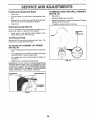
CAUTION: BEFORE PERFORMING ANY SERVICE OR ADJUSTMENTS:
o Depress clutch/brake pedal fully and set parking brake,
•
Place motion control lever in neutral (N) position,
o
Place attachment clutch in "DISENGAGED"
position.
o Turn ignition key "OFF" and remove key°
o
Make sure the blades and all moving parts have completely stopped.
o
Disconnect spark plug wire from spark plug and place wire where it cannot come in contact with
plug.
TRACTOR
TO REMOVE
TO LEVEL
MOWER
PTace attachment clutch in "DISENGAGED"
°
Turn height adjustment knob to lowest setting.
o
Lower mower to its lowest position.
°
Remove retainer spring holding anti-swaybar to chassis bracket and disengage anti-swaybar from bracket.
°
Remove retainer springs from suspension
deck and disengage arms from deck°
o
Raise attachment lift to its highest position,
o
Remove two retainer springs from each front link and
remove links.
o
Slide mower forward and remove belt from electric
clutch pulley.
position_
SIDE-TO-SIDE
arms at
Slide mower out from under right side of tractor.
IMPORTANT: IF AN ATTACHMENT OTHER THAN THE
MOWER DECK 1STO BE MOUNTED ON THE TRACTOR,
REMOVE THE FRONT LINKS
MOWER
LIFT
LINKS
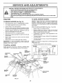
(See Figs, 19 and 20)
Raise mower to its highest position,
-
Measure height from bottom of deck curl to ground
level at front corners of mower_ Distance "A" on both
sides of mower should be the same
°
If adjustment is necessary, make adjustment on one
side of mower only
°
To raise one side of mower, tighten lift link adjustment
nut on that side,
,
To lower one side of mower, loosen lift link adjustment
nut on that side,
NOTE: Each half turn of adjustment nut will change mower
height about 3/16".
Recheck measurements
after adjusting
BOTTOM
OF CURL
Follow procedure described in "INSTALL MOWER AND
DRIVE BELT" in the Assembly section of this manual
SUSPENSION
ARMS
ADJUSTMENT
o
o
TO INSTALL
HOUSING
Adjust the mower while tractor is parked on level ground or
driveway
Make sure tires are properly inflated (See
"PRODUCT SPECIFICATIONS" on page 3 of this manual).
If tires are over or underinfiated, you wilt not properly adjust
your mower.
(See Fig. 19)
•
MOWER
BOTTOM
OF CURL
FRONT
SUSPENSION
BRACKET,
ADJUSTMENT
NUTS
CHASSIS
ELECTRIC
CLUTCH
PULLEY
FRONT
SUSPENSION
BRACKET
RETAINER
RETAINER
SPRING
ANTI-SWAY
BAR
FRONT MOWER
BRACKET
RETAINER
SPRINGS
FIG. 19
21
TO REPLACE
FRONT-TO-BACK ADJUSTMENT (See Figs. 21 and 22)IMPORTANT: DECK MUST BE LEVEL SIDE-TO-SIDE. IF
THE FOLLOWING FRONT-TO-BACK ADJUSTMENT tS
NECESSARY, BE SURE TO ADJUST BOTH FRONT LINKS
EQUALLY SO MOWER WILL STAY LEVEL SIDE-TO-SIDE ',
MOWER
DRIVE
BELT
MOWER DRIVE BELT REMOVAL (See Fig. 23) -
To obtain the best cutting results, the mower housing
should be adjusted so the front is approximately 1/8" to 1/2"
lower than the rear when the mower is in its highest
position,
Check adjustment on right side of tractor. Measure distance "F" directly in front of and behind the mandrel at
bottom edge of mower housing as shown.
•
Before making any necessary adjustments, check that
both front links are equal in length.
o If links are not equal in length, adjust one link to same
length as other link_
•
Tolowerfront of mower housing, loosen nut"G"on both
front links an equal number of turns.
When distance "F" is 1/8" to 1/2" lower at front than
rear, tighten nut"H" against trunnion on both front links°
•
To raise front of mower housing, loosen nut "H" from
trunnion on both front tinks_ Tighten nut "G" on both
front links an equal number of turns.
When distance "F" is t/8" to 1/2" lower at front than
rear, tighten nut "H" against trunnion on both front
links.
•
o
Park tractor' on a level surface. Engage parking brake.
Remove four screws from Loll, mandrel cover' and
remove cover.
°
Roll belt over the top of L H,, mandrel pulley,,
o
=
Remove belt from electric clutch pulley,
Remove belt from idler pulleyso
o
Remove any dirt or grass clippings which may have
accumulated around mandrels and entire upper deck
sudace.
,
Check primary idler arm and two idlers to see that they
rotate freely.
•
Be sure spring is securely hooked to primary idler' arm
and bolt in mower housing,,
MOWER DRIVE BELT INSTALLATION (See Fig. 23) e
Install belt in both idlers. Make sure belt is in both belt
keepers at the idlers as shown
NOTE: Each full turn of nut "G" will change dim. "F" by
approximately 3/8".
o Recheck side-to-side adjustrnent.
*
Install new belt onto electric clutch pulley.
.
Roll belt into upper groove of L.Ho mandrel pulley,
-
Carefully check belt routing making sure belt is in the
grooves correctly and inside belt keepers.
Reassemble L.H. mandrelcover,
o
SCREWS
L.H.
MANDREL
COVER
IDLER
MANDREL
ELECTRIC
CLUTCH
PULLEY
SPRING
PULLEYS
\
PRIMARY
IDLER
ARM
FIG. 21
BOLT IN
BOTH FRONT LINKS SHOULD BE EQUAL IN LENGTH
HOUSING
MANDREL
\
\
\
\
MOWER
DRIVE BELT
BELT
KEEPER
FIG. 23
NUT "H" _
FRONT LINKS
FIG. 22
22
SERVnCE AN
i,
TO REPLACE
(See Fig. 24)
MOWER
BLADE
i,, ,
DRIVE
ADJUSTMENTS
i
Park the tractor on level surface_ Engage parking brake.,
.
Remove mower drive belt (See"TO REPLACE MOWER
DRIVE BELT" in this section of this manual)°
o Remove mower (See "TO REMOVE MOWER" in this
section of this manual),
.
Remove four screws from R.H mandrel cover and
remove cover° Unhook spring from bolt on mower
housing.
•
Carefully rol! belt off RH_ mandrel pulley
Remove belt from center mandrel pulley, idler pulley,
and L,,H. mandrel pulley.
o Remove any dirt or grass which may have accumulated around mandrels and entire upper deck surface,,
.
Check secondary idler arm and idfer to see that they
rotate freely
o
Be sure spring is hooked in secondary idler arm and
sway-bar bracket.
•
Install new belt in lower groove of L,,H. mandrel puUey,
idler pulley, and center mandrel pulley as shown.
•
Roll belt over R.H. mandrel puliey- Make sure belt is in
all grooves properly,
.
Reconnect spring to bolt in mower housing and reinstall RH mand[el cover.
Reinstall mower to tractor (See "INSTALL MOWER
AND DRIVE BELT" in the Assembly section of this
manual)°
•
Reassemble mower drive belt (See "TO REPLACE
MOWER DRIVE BELT" in this section of this manual),
LH,
MOWER BLADE
DRIVE BELT
ii ,, i
ii1,, i
i
iiipi,
i1_1111illllll
i
..................
NOTE: After instalting a new electric clutch, run tractor at
full throttle and engage and disengage electric clutch 10
cycles to wear in clutch p_ate_
BELT
RO_
CLUTCH
PLATE
o012"
SLOT {3
/
NYLON LOCKNUT (3)
BRAKE
PLATE
FIG. 25
TO ADJUST
BRAKE
(See Fig. 26)
Your tractor is equipped with an adjustable brake system
which is mounted on the side of the transaxle
If tractor requires more than six (6) feet stopping distance
at high speed in highest gear, then brake must be adjusted.
CENTER
MANDREL
MANDREL
COVER
°
Depress clutch/brake pedal and engage parking brake.
•
Measure distance between brake operating arm and
nut "A" on brake rod,
,,
tf distance is other than 1-1/2", loosen jam nut and turn
nut "A" until distance becomes t-1/2L Retighten jam
nut against nut "A".
-
Road test tractor for proper stopping distance as stated
above Readjust if necessary, if stopping distance is
still greater than six (6) feet in highest gear, further
maintenance is necessary. Contact your nearest authorized service centeddepartment..
WITH PARKING
BRAKE "ENGAGED"
NUT "A"
/SCREW
JAM NUT
SECONDARY
IDLER ARM
"/"'"i
I
_
,J
TO ADJUST
ATTACHMENT
,
L.,
CLUTCH
(See Fig. 25)
The electric clutch should provide years of service, The
clutch has a built-in brake that stops the pulley within 5
seconds. Eventually, the internal brake will wear which
may cause the mower blades to not engage, or, to not stop
as required, Adjustments should be made by your nearest
authorized service center/department,
o Make sure attachment clutch and ignition switches are
in "OFF" position,,
.
Adjust the three nylon tocknuts until space between
clutch plate and rotor measures .,012" at all three slot
locations cut in side of brake plate.
FIG. 26
23
OPERATING
=
SERVICE AN
TO REPLACE
(See
MOTION
DRIVE
ADJU
Fig. 27)
Engage parking brake (creates slack in belt)o
°
Remove belt from clutching and fan idler pulleys.
o
Remove belt from transaxle pulley.
•
Remove
pulley.
o
Pull belt out of all belt keepers and remove from tractor_
If for any reason the motion control lever wilt not hold its
position while at a selected speed, it may be adjusted at the
friction pack located on the right side of chassis.
belt from engine pulley and front V-idler
BELT INSTALLATION
Park tractor on level surface° Stop tractor by turning
ignition key to "OFF" position and engage parking
brake.
=
Place motion control lever in neutral (N) position.
=
While holding Iocknut, loosen jam nut
•
Tighten locknut 1/4turn.
,
While holding Iocknut, tighten jam nut securely.
Road test tractor after adjustment and repeat procedure if
necessary.
Route belt on right side, coming from V-idler, towards
back of tractor, above midspan belt keeper and to top
of transaxle pulley.
LOCKNUT
Route belt on left side, coming from engine pulley,
towards back of tractor and through loop in midspan
belt keeper'.
,
Place V part of belt into grooves on transaxle and fan
idler pulleys, making sure to route belt inside of all belt
keepers°
o
Place belt around clutching idlers as shown, making
sure to rou_e belt inside of all belt keepers,
o
Check to be sure belt is positioned correctly and is on
proper side of all belt keepers°
Reinstall mower.
°
=
NOTE: If for' any reason the effort to move the motion
control lever becomes too excessive, reverse the above
adjustment procedure by loosening tocknut 1/4 turn.
-
Place V part of belt into grooves on engine pulley and
front V-idler, making sure to route belt inside of all belt
keepers.
•
IMPORTANT:
LEVER
The motion control lever has been preset at the factory and
adjustment should not be necessary..
Remove mower (See "TO REMOVE MOWER" in this
section of this manual.)
•
,
CONTROL
(See Fig. 28)
BELT REMOVAL
°
ENT$
TO ADJUST,MOTION
BELT
Park the tractor on fevet surface° Engage parking brake.
For ease of service there is a belt installationguide decal on
bottom of left footrest,
o
,,,Hf
CHECK
BRAKE
JAM NUT
ADJUSTMENT,
TRACTOR V-BELT DRIVE SCHEMATIC
VIEWED FROM L,H, SIDE OF TRACTOR
CLUTCHING
CLUTCHING
ENGINE
PULLEY
|DLER_
TRANSAXLE
FIG. 28
BELT
ABOVE
VJDLER
TRANSMISSION
REMOVAL/REPLACEMENT
KEEPER
Should your transmission require removal for service or
replacement, it should be purged after reinstallation before
operating the tractor° See "PURGE TRANSMISSION" in
Operation section of this manual
BELT
TWISTS
BELT
KEEPER
TO ADJUST
FAN
IDLER
STEERING
WHEEL ALIGNMENT
tf steering wheel crossbars are not horizontal (left to right)
when wheels are positioned straight forward, rernove steering wheel and reassemble per instructions in the Assembty
section of this manual
AS VIEWED FROM BOTTOM
FIG. 27
24
FRONT
WHEEL TOE-IN
ADJUSTMENT
Front wheei toe-in is required for proper stee ring operation_
Toe-in was set at the factory and adjustment should not be
necessary., If parts in the front axle or steering mechanism
have been replaced or damaged, check toe-in and adjust
if necessary.
RETAINING
RING
AXLE
(;OVER
"-,..,.
TO CHECK TOE-IN (See Fig. 29) o
Position front wheels straight ahead,
.
Measure distance between wheels at front and rear of
tires (dimensions "A" and "B")°
Front dimension "A" should be 1/8" to 1/4" less than
rear dimension "B",
,
FIG, 31
REAR WHEEL .
o
TO ADJUST TOEqN (See Figs. 29 and 30) -
Loosen jam nuts at adjustment sleeves on tie rod.
.
Adjusttieroduntildimension"A"ist!8"tol/4"Iessthan
dimension "B'L
•
Tighten jam nuts securely.
Block rear axle securely
Remove five (5) hub bolts to allow wheel removal
Repair tire and reassemble. Replace and tighten hub
belts securely,
TOSTART
ENGINE
WITH A WEAK
BATTERY
See Fig. 32)
_d
"__-.Keep
__ls
" _
,,
batteries gener *
sparks, flame
away from bat*
I
I
protectionI
when around batteries,
when
batteriesl
....
I
If your battery is too weak to start the engine, it should be
recharged,
If "jumper cables" are used for emergency
starting, follow this procedure:
IMPORTANT: YOUR TRACTOR iS EQUIPPED WITH A t 2
VOLT NEGATIVE GROUNDED SYSTEM
THE OTHER
VEHICLE MUST ALSO BE A 12 VOLT NEGATIVE
GROUNDED SYSTEM. DO NOT USE YOUR TRACTOR
BATTERY TO START OTHER VEHICLES
FIG. 29
TO ATTACH JUMPER CABLES
°
Connect each end of the RED cable to the POSITIVE
(¥) terminal of each battery, taking care not to short
against chassis
Connect one end of the BLACK cable to the NEGATIVE (-) terminal of fully charged battery
Connect the other end of the BLACK cable to good
CHASSIS GROUND, away from fuef tank and battery.,
TO REMOVE CABLES, REVERSE ORDER -
FIG. 30
FRONT WHEEL
•
CAMBER
The front wheel camber is not adjustable on your tractor° If
damage has occurred to affect the front wheel camber,
contact your nearest authorized service center/department.
TO REMOVE
WHEEL
FOR REPAIRS
FRONT WHEEL (See Fig 3I) o
o
Block up axle securely..
Remove axte cover, retaining ring and washers to allow
wheel removal°
.
•
Repair tire and reassembfe.
Replace washers and snap retaining ring securely in
axle groove
Replace axle cover..
•
BLACK cable first from chassis and then from the fully
charged battery.
RED cable Iast from both batteries,.
"POSITIVE"
25
(+)
"NEGATIVE"
Pit=. 32
(-)
...................................
i ,,,u
.....
ADJUSTMENTS
,
i n,,lu,
,,nnni
TO REMOVE HOOD AND GRILL
(See Fig. 34)
Pull bulb holder out of the hole in the backside of the
grill
•
Raise hood.
°
Unsnap headlight wire connector.
Replace bulb in holder and push bulb holder securely
back into the hole in the backside of the grill.
•
Stand in front oftractor, Grasp hood at sides, tilt toward
engine and lift off of tractor.
Close hood.
•
To replace, reverse above procedures.
INTERLOCKS
AND
RELAYS
Loose or damaged wiring may cause your tractor to run
poorly, stop running, or prevent it from starting°
o
ASSEMBLY
HEADLIGHT
WIRE
CONNECTOR
Check wiring. See electrical wiring diagram in the
Repair Parts section of this manual
TO REPLACE
HOOD
FUSE
\
Replace with 30 amp automotive-type p!ug-in fuse_ The
fuse holder is located behind the dash.
TO ADJUST ATTACHMENT
(See Fig. 33)
) ,,
LIFT SPRING
o
White holding spring bushing with wrench, loosen jam
nut.
,
Turn adjustment bolt clockwise to extend spring and
reduce lift effort for heavier attachments.
=
Turn adjustment bolt counterclockwise
tachments
•
for lighter atFIG. 34
,
Retighten jam nut against spring bushing.
IMPORTANT: DO NOT ADJUST FOR MAXIMUM SPRING
TENSION WHEN USING LIGHT ATTACHMENTS SUCH
AS A MOWER. ADJUST LIFT LEVER SPRING TO AID IN
LIFTING ATTACHMENT. DO NOT OVERPOWER SPRING,
WHEN REMOVING ATTACHMENT, ALWAYS ADJUST
SPRING TENSION TO ITS LOWEST POSITION.
ADJUSTMENT
SPRING BUSHING
e
JAM NUT
o
(,
ATTACHMENT
LIFTSPRING
o
FIG. 33
26
SERVmCE AND ADJUSTMENTS
...................
I,NII, m i1,,i, ii, i .................
ENGINE
TO
ADJUST
CLOSED
FOR
THROTTLE
CONTROL
CABLE
(See Fig. 35)
The throttle control has been preset at the factory and
adjustment should not be necessary. Check adjustment as
described below before loosening cable. If adjustment is
necessary, proceed as follows:
•
With engine not running, move throttle control lever to
fast (,_) position.
•
Check that speed control lever is against stop screw. If
it is not, !oosen casing clamp screw and pull throttle
cable until lever is against screw.. Tighten clamp screw
securely.
CLAMP SCREWS
CHOKE
CONTROL
CABLE
j
FIG. 36
TO ADJUST
THROTTLE
CONTROL
CABLE
IDLE SPEED
ADJUSTMENT
SCREW
FIG. 35
TO ADJUST
CHOKE
CARBURETOR
(See
Fig. 35)
The carburetor has been present at the factory and adjustment should not be necessary. However, minor adjustment
may be required to compensate for differences in fuel,
temperature, altitude or load If the carburetor does need
adjustment, proceed as follows:
•
Be sure you have a clean air filter and the throttle
control cabfe is adjusted property (see above)°
,
Start engine and allow to warm for five minutes. Make
finaf adjustments with engine running and shift/motion
control lever in neutral (tt) position
°
The high idle is set at the factory and cannot be
adjusted.
°
ld{e speed settinq - With throttle control tever in slow
(,_)
position, _ngine should idle at 1200 RPM If
engine idles too slow or fast, turn idle speed adjusting
screw in or out until correct idle is attained
NOTE: The carburetor on this engine is Iow emission it is
equipped with an idle fuel needle with a limiter cap and is
not adjustable. Do not attempt to remove the fimiter cap.
The iimiter cap cannot be removed without breaking the
adjusting needle.
High speed stop is factory adjusted Do not adjust-damage
may result.
IMPORTANT:
NEVER TAMPER WiTH THE ENGINE
GOVERNOR, WHICH IS FACTORY SET FOR PROPER
ENGINE SPEED.. OVERSPEEDING THE ENGINE ABOVE
THE FACTORY
HiGH SPEED SETTING
CAN BE
DANGEROUS iF YOU THINK THE ENGINE-GOVERNED
HIGH SPEED NEEDS ADJUSTING, CONTACT YOUR
NEAREST
AUTHORIZED
SERVICE
CENTER/
DEPARTMENT, WHICH HAS PROPER EQUIPMENT AND
EXPERIENCE
TO
MAKE
ANY
NECESSARY
ADJUSTMENTS
CONTROL
(See Figs. 35 and 36)
The choke control has been preset at the factory and
adjustment should not be necessary, check adjustment as
described below before loosening cable_ tf adjustment is
necessary, proceed as follows:
*
With engine not running, move choke control (located
on dash panel) to fu!l choke (N) position..
Remove air cleaner cover, filter and cartridge plate to
expose carburetor choke (See "AIR FILTER" in the
Customer Responsibilities section of this manual).
°
Choke should be dosed,
if it is not, loosen casing
clamp screw and move choke cable until choke is
completely closed. Tighten casing clamp screw securely..
Reassemble air cleaner,
27
, i,iii1,1,1111
....
i
iii ,i,,
,
i
STORAGE
ENGINE
Immediately prepare your tractor for storage at the end of
the season or' if the tractor will not be used for 30 days or
more°
i
ii
,
,
i i,ii
iiii
I
I
FUEL SYSTEM
I
IMPORTANT:
IT IS IMPORTANT TO PREVENT GUM
DEPOSITS FROM FORMING IN ESSENTIAL
FUEL
SYSTEM PARTS SUCH AS CARBURETOR, FUEL FILTER,
FUEL HOSE, OR TANK DURING STORAGE.
ALSO,
EXPERIENCE INDICATES THAT ALCOHOL BLENDED
FUELS (CALLED GASOHOL OR USING ETHANOL OR
METHANOL) CAN ATTRACT MOISTURE WHICH LEADS
TO SEPARATION AND FORMATION OF ACIDS DURING
STORAGE.
ACIDIC GAS CAN DAMAGE THE FUEL
SYSTEM OF AN ENGINE WHILE IN STORAGE.
gasoline in the tank inside a building
where
fumes
may store
reachthe
an tractor
open flame
CAUTION:
Never
with
or spark, Allow the engine to cool
before storing in any enclosure.
,i,ii i ii iii IH,,
TRACTOR
Remove mower from tractor for winter storage° When
mower' is to be stored for a period of time, clean it thoroughly, remove all dirt, grease, leaves, etc. Store in a
clean, dry area.
o
Clean entire tractor (See"CLEANING" inthe Customer
Responsibilities section of this manual).
•
Inspect and replace belts, if necessary (See belt replacement instructions in the Service and Adjustments
section of this manual)_
•
Lubricate as shown in the Customer Responsibilities
section of this manual.
•
Be sure that all nuts, bolts and screws are securely
fastened. Inspect moving parts for damage, breakage
and wear_ Replace if necessary.
o
Touch up all rusted or chipped paint surfaces; sand
lightly before painting.
Fully charge the battery for storage_
=
After a period of time in storage, battery may require
recharging.
°
To help prevent corrosion and power leakage durng
long periods of storage, battery cables should be
disconnected and battery cleaned thoroughly (see "TO
CLEAN BATTERY AND TERMINALS
in the Customer Responsibilities section of this manual).
o
Drain the fuet tank.
.
Start the engine and let it run until the fuel lines and
carburetor are empty.
•
Never use engine or carburetor cleaner products in the
fuel tank or permanent damage may occur.
Use fresh fuel next season.
°
NOTE: Fuel stabilizer is an acceptable alternative in
minimizing the formation of fuel gum deposits during storage. Add stabilizer to gasoline in fuel tank or storage
container_ Always follow the mix ratio found on stabilizer
container. Run engine at least 10 minutes after adding
stabilizer to allow the stabilizer to reach the carburetor. Do
not drain the gas tank and carburetor if using fuel stabilizer,
ENGINE OIL
Drain oil (with engine warm) and replace with clean engine
oil. (See "ENGINE" in the Customer' Responsibilities
section of this manual).
BATTERY
•
,,
CYLINDERS
°
Remove spark plug(s).
,
Pour one ounce of oil through spark plug hole(s) into
cylinder(s)o
Turn ignition key to"START" position for a few seconds
to distribute oil.
•
After cleaning, leave cables disconnected and place
cables where they cannot come in contact with battery
terminals.
Replace with new spark plug(s).
OTHER
=
Be sure battery drain tube is securely attached,
•
Do not store gasoline from one season to another_
.
If battery is removed from tractor for storage, do not
store battery directly on concrete or damp surfaces.
•
Replace your gasoline can if your can starts to rust.
Rust and/or dirt in your gasoline will cause problems.
•
If possible, store your tractor indoors and cover' it to
give protection frorn dust and dirt°
•
Cover your tractorwith a suitable protective cover that
does not retain moisture. Do not use plastic. Plastic
cannot breathe which allows condensation to form arid
will cause your tractor to rusL
IMPORTANT: NEVER COVER TRACTOR WHILE ENGINE
AND EXHAUST AREAS ARE STILL WARM..
28
TROU
LESHOO'F NG
PROBLEM
CAUSE
Will not start
!
Out of fuel
2
3
4
5
6
7
Engine not"CHOKED"
Engine flooded
Bad spark ptug
Dirty air filter
Didy fuelfilter,
Water in fuel
8,
9
!0
i,,,,U,lUl,,,n
Hard to start
,u
POINTS
CORRECTION
properly
1
Fill fuel tank
2
3
4,
5
6
7
See 'q'o START ENGINE" in Operation section
Wait several minutes before attempting to start
Replace spark plug
Clean/replace air filter
Replace fuel filter
Drain fuel tank and carburetor, refill tank with fresh
gasoline and replace fuel filter
Check allwiring
Contact an authorized service center!department
Contact an authorized service center/department
Loose or damaged wking
Carburetor out of adjustment
Engine valves out of adjustment
8
9,
10
Dirty air filter,
Bad spark plug
Weak or dead battery
Dirty fuel filter
Stale ordirty fuel
Loose or damaged wiring
Carburetor out of adjustment
Engine valves out of adjustment
1
2
3
4
5
6
7
8
Clean/replace air filter
Replace spark ptug
Recharge or replace baflery
Replace fuel filter
Drain fuel tank and refill with fresh gasoline
Check al_ wiring
Contact an authorized service center/department
Contact an authorized service center/department
Depress clutch/brake pedal
Disengage attachment clutch
Recharge or replace battery
Replace fuse
Clean battery terminals
Check all wiring
ChecWreplace ignition switch
Checidreplace solenoid or starter
Contact an authorized service center/department
i
1
2,
3
4,
5
6,
7,
8
,,,,llU,,nl,,
Engine will not turn over
1
2
3
4
Clutch/brake pedal not depressed
Attachment clutch is engaged
Weak ordead battery
Blown fuse
5
6
7
8
g
Corroded batten/terminals
Loose or damaged wiring
Faulty ignition switch
Faulty solenoid or starter
Faulty operator presence switch(es)
1
2
3
4
5
6
7
8
9
Engine clicks but will not
start
1
2
3.
4
Weak or dead battery
Corroded battery terminals
Loose or damaged wiring
Faulty solenoid or starter
I
2
3
4,
Recharge or replace battery
Clean battery terminals
Check all wiring
Check!replace solenoid or starter
Loss of power
1
2
3
4
5
6
7
8
g
Cutting too much grass/too fast
Throttle in "CHOKE" position
Build-up of grass, leaves and trash under mower,
Dirty air filter
Low oil level/dirty oil
Faulty spark plug
Dirty fuel filter.
Stale or dirty fuel
Water in fuel
t
2
3
4
5
6
7
Set in "Higher Cut" position/reduce speed
Adiust throttle control
Clean underside of mower housing
Clean!replace air filter
Check oil level/change oil
Clean and regap or change spark plug
Replace fuel filter
8
9
10
11
t2
Drain fuel tank and refil! with fresh gasoline
Drain fuel tank and carburetor, refill tank with fresh
gasoline and replace fuel filter
Connect and tighten spark plug wire
Clean engine air screen/lids
Clean!replace muffler
!3
I4
15
CheckaIt wiring
Contact an authorized
Contact an auIhorized
10
11
12
13
14
15
i,,,
Excessive
,,llllll,
vibration
Spark plug wire loose
Dirty engine air screen/fins
Didyiciogged muffler
Looseor damaged wiring
Carburetor oat of adjustment
Engine valves out of adjustment,
service center/department
service center/department
nl, i
1
2,
Worn, bent or loose blade
Bent blade mandrel
1
2
Replace blade Tighten blade boll
Replace blade mandrel
3
Loose!damaged
3
Tighten loose pad(s)
pad(s)
29
Replace damaged parts
= =
PROBLEM
CAUSE
H,H==
CORRECTION
H '1
Engine continues to run
when operator leaves seat
with attachment clutch
....
'HLI
,',,H N
,= H '
1,
Faulty operator-safety
presence control system,
1
Check wiring, switches and connections If not
corrected, contact an authorized service canted
department
1
2.
3
4
Worn, bent or loose blade
Mower deck not level,.
Buildup of grass, leaves, and trash under mower
Bent blademandrei
1
2,
Replace blade Tighten blade bolt
Level mower deck.
5
Clogged mower deck vent holes from buildup of
grass, leaves, and trash around mandrels
3,
4
5
Clean underside of mower housing
Replace blade mandrel,
CJean around mandrels to open vent holes
!
2
3.
4,
Obstruction in clutch mechanism
Worn/damaged mower drive belt
Frozen idler puitey,
Frozen blade mandrel
1
Remove obstruction
2
3.
4.
Replace mower drive belt
Replace idler pulley.
Replace blade mandrel
1
2,
3
4
Engine speed too slow
Travel speed too fast
Wet grass
Mower deck not level.
1,
2,
3.
4
Place throttie control in "FAST" position
Shift to slower speed.
Allow grass to dry before mowing,
Level mower deck
5
6
7,
8
Lowfuneven tire a_r pressure.
Worn, bent or loose blade
Buildup of grass, leaves and trash under mower,
Mower drive belt worn.
5
6
7
8
Checktires for proper air pressure,
Replacetsharpen blade Tighten blade boil,
Clean underside of mower housing
Reptace mower drive belt
9.
10
11
Blades impropedy installed,
improper blades used
Clogged mower deck vent holes from buildup of
grass, leaves, and trash around mandrels
9
10
11,
engaged
Poor cut - uneven
, =,=1,11,1,,,
Mower blades will not
rotate
H=H,, '1
Poor' grass discharge
i
Reinstall blades sharp edge down
Replace with blades listed in this manual
Clean around mandrels to open vent holes
= =l
Headlight(s) not working
(if so equipped)
1
2,
3,
4
5.
Switch is "OFF".
Bulb(s) burned out.
Faulty light switch
Loose or damaged wiring
Blown fuse.
Battery will not charge
1.
2.
Bad battery cell(s),
Poor cable connections
3.
4
Faulty regulator (if so equipped).
Faulty alternator,
!,
Turn switch "ON"
2
3
4
5.
Replace bulb(s),
Check/replace light switch.
Check wiring and connections
Replace fuse
1
2.
3
4
Replace battery
Check/clean aH connections
Replace regulator
Replace afternator
=================1
Loss of drive
1.
2
3
Freewheel control tn "disengaged" position.
Motion drive beE!worn, damaged or broken,
Air trapped in transmission during shpmant
or servicing
1
2,
3
Place freewheel contreJ in "engaged" position
Replace motion drive belt.
Purge transmission
=======
=========
==
===
Eng|ne "backfires"
when turning engine
"OFF"
HHHH=I=
HHH==
Engine throttle control not set at "SLOW'
Move throtUe control to "SLOW" position and allow
position for 30 seconds before stopping engine.
to idle for 30 seconds before stopping engine
H,rH,, =1
=======1=1
I
'1
3O
"