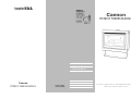
1
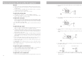
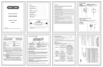
Cannon
FITZROY FREESTANDING
FREESTANDING MODELS
FITZFS-SDSEB-NG
FITZFS-SDSEB-LP
USER INSTRUCTIONS
Cannon
FITZROY FREESTANDING
INSTALLATION INSTRUCTIONS
Part No: F2904
Revision D-2009
SERVICE INSTRUCTIONS
This heater is approved for use with Natural and Propane gases.
Please leave instructions with the owner
Contents
Contents
2
❍ Distributor
Warranty
Safety warnings
3
4-5
❍ What to do if you smell gas
❍ Warnings
❍ Standards
User instructions
6-8
❍ Operating instructions
❍ Flame characteristics
❍ Cleaning
Heater specifications
Installation instructions
❍
❍
❍
❍
❍
❍
❍
9
10-15
Clearances
Installation
Gas connection
Log installation
Gas control
Gas pressure point
Installation tips
Flue installation
16-17
❍ Flue kit
Service instructions
❍
❍
❍
❍
❍
❍
❍
❍
❍
❍
❍
❍
18-20
General
To replace primary glass
To replace outer glass
To replace the gas control
To replace the ignition (module) device
To replace the room circulation fan
To replace the fan pressure switch
To remove the heat exchanger
To replace the burner and spark/sense electrodes
Wiring diagram
Data label
For service to this appliance
Trouble shooting
21-22
❍ Connections
2
23
Warranty
9.
10.
11.
No gas to burner.
Appliance lights but goes
into lockout.
Fuse blowing.
• The gas valve should open at the same time as the
igniter sparks. If there is no gas to the burner when
this occurs check the solenoid coils for continuity.
• Check that the gas pressure is present at the test
point when the spark is being generated.
• Check that there is gas to the inlet of the gas control.
The Cannon appliance is warranted against defects in materials and workmanship for a period of one, (1) year from its date of original purchase, for
residential use in Australia.
• Test the flame for correct ionisation signal. Connect a
multimeter in series with the flame rod and set the
function to measure micro-amps. The module will go
into lockout if the flame current sensitivity is less than
0.5 micro-amps. The approximate signal strength on
high flame is about 10 micro-amps and on low
4 micro-amps. The signal strength will fluctuate but
should be greater than 1.5 micro-amps at all times.
Take precaution because the ionisation probe can
have a high negative voltage and can cause shock.
Consumers are responsible for service person’s travel outside normal service areas (approximately seventy (70k) radius from the nearest Cannon
dealer’s location), local cartage, and normal maintenance as described in
this manual.
• If the fuse continues to blow check the solenoid coils
for signs of them being shorted.
• Check the fan and wiring for short circuit.
The customer must keep their “Tax Invoice” as proof of purchase of this
product, and compliance certificate as proof of required installation.
Connections
Warranty service, which includes parts and labour for the replacement or
repair of defective parts, is available through the CANNON distributor.
(Details below or on page19).
Any product subjected to misuse, abuse, negligence, accident or alteration
will have its warranty voided. The defacement of serial plate will have its
warranty voided.
If installation is not carried out in accordance with manufacturer’s instructions, this warranty may be void.
Model number: ______________________________________
Terminals 5, 6 and 7 at the module 12 way connector are bridged.
Terminal 10 at the module 12 way connector is the active supply via the
red wire.
Terminal 11 at the module 12 way connector is the neutral supply via the
blue wire.
Terminal 12 at the module 12 way connector is the earth connection via
the green/yellow wire.
Terminal 12 at the module 2 way connector is the neutral connection via a
brown wire which is joined into the rectifier cable then into the 8 way
switch connector blue wire.
Terminal 14 is an active connection at the module 2 way connector via a
white wire into the 8 way switch connector. This is active only when the
flame is sensed.
Serial number: _______________________________________
Date of manufacture: _________________________________
Date installed: _______________________________________
Compliance Certificate No: ____________________________
Don’t risk your appliance warranty
Only a licensed person will give you a Compliance Certificate,
showing that the work complies with all the relevant standards.
And only a licensed person will have insurance protecting their
workmanship for 6 years.
So make sure you use a licensed person to install this appliance
and ask for your Compliance Certificate to ensure the manufacturers appliance warranty will be honoured.
Distributor
This appliance is designed, manufactured and distributed by:
28
22
Tel: 1300 727 421
3
Safety warnings
Please read this manual before installing and using the heater.
What to do if you smell gas
1. Turn OFF the main gas supply.
2. Extinguish any open flame.
3. Open windows.
Trouble-shooting. (Do not modify this appliance).
To check the operation of the electronic (module) controller (Type 537 ABC) you will require a digital
multimeter with the functions to measure AC/DC voltage, continuity, resistance and micro-amps.
It is critical that the appliance is earthed and that the active and neutrals are not reversed.
Item No
Check
Action
1.
No ignition when appliance
is turned on.
• Check 240 volts power to heater in incoming plug
connector.
2.
Power present but appliance
not operating.
• If there is power to the brown wire in the 8 way
switch connector the module may be in lockout
mode. To reset the module turn off the power supply
for 10 seconds and then turn the power on again.
3.
After resetting the module
and appliance is still not
operating.
• Check the internal 2-A fuse in the loom.
4.
If the fuse is O.K. and still
appliance not operating
• Check other connections are in place.
• If the last checks are correct the ignition electrode
should spark at the same time as the gas control
solenoid valves open. At this point the spark
electrode will activate for up to 10 seconds maxi
mum until the flame has been established. Terminal
14 (white wire into the 8 way switch connector)
will be energised as soon as the flame has been
sensed.
5.
Confirm spark is produced
when heater is turned on.
• A blue spark can be seen when the heater ignition
process starts. Ensure spark is present between
electrode and burner.
6.
If no spark being produced
• Check that spark lead is connected into module.
• Check the continuity of the HT cable.
• Check that there is no short circuit to earth and
spark gap is correct. (Refer figure 28). A positive
check is to use a jumper wire and connect one end
of the earth and hold the other end with insulated
pliers 4mm from the spark generator on the module.
If there is no spark to earth then change the module.
7.
Spark is being produced
but not at burner.
• Listen for cracking sound. The spark is misdirected.
Check the spark ceramic insulator for signs of
cracks.
8.
Sparks, ignites on low flame
then extinguishes after 10
seconds. Continues to spark
during flame presence.
• Check that the wall socket to the appliance has
correct polarity. Do not use an extension cord. Check
polarity in the electrical supply lead to appliance.
• Check that the sense electrode is in the flame.
• Check that appliance is earthed correctly. A check
between the earth pin on the plug and an unpainted
part of the appliance should see a resistance of
0.1 ohms.
4. Do not touch electrical switches.
5. Do not use your telephone.
6. Call your gas supplier immediately from a neighbour’s phone.
Warnings
1. Improper installation, adjustment, alteration, service or maintenance
can cause injury or property damage. Refer to other sections of this
manual for correct procedures, or consult with place of purchase, a
licensed plumber, a gas supplier or the CANNON distributor listed in
this manual.
2. Do not build the heater into bookcases or walls. Install only as referred
to in these installation instructions.
3. Due to high temperatures the room heater should be located out of
traffic and away from:
•
•
•
Furniture and draperies,
Combustible materials,
Gasoline and other flammable liquids,
Do not place clothing or other flammable material on or near the heater.
4. Keep curtains*, clothing, furniture and other flammable materials at
least 900mm from front, rear and sides of the heater.
* At the owner’s discretion curtain clearance can be less than 900mm
as long as they are restrained from the front, top and sides of the heater.
The manufacturer takes no responsibility if curtain clearance is less than
900mm and not restrained.
5. Children and adults should be alerted to the hazard of high surface
temperature and should take care to avoid burns or clothing ignition.
This appliance is not intended for use by persons (including children) with reduced physical, sensory or mental capabilities, or lack
of experience and knowledge, unless they have been given supervision or instruction concerning use of the appliance by a person
responsible for their safety.
Children should be supervised to ensure that they do not play with
the appliance.
6. Never attempt to burn paper or any other material in the heater.
7. Do not place articles on or against this appliance.
Do not use or store flammable materials near this appliance.
4
21
Wiring diagram
Do not spray aerosols in the vicinity of this appliance while it is in
operation.
Do not modify this appliance.
8. If removed, the glass window must be put back onto the unit prior to
operating the heater.
9. Installation and repairs should be performed by a licensed service
person only, refer to back of brochure for service number.
10. The appliance should be inspected prior to use, with regular inspections (annually) to be made by a licensed service person. It is important
that circulating air passageways of the appliance be kept clean, dirt
and lint free, for a safe and efficient operation of the heater.
11. On first lighting your heater a smell may occur due to its new condition. This is quite normal and will disappear after a few hours use at
the maximum control position.
12. Testing the effectiveness of the flue.
Before testing the flue confirm air vents are unobstructed. If an exhaust
fan or other heating appliances are present switch them on. This is to
test that there is no interaction between the CANNON heater and
other appliances.
Refer AS5601.
For ‘air movement not to affect appliance’ see clause 5.3.1.
For ‘air supply to appliance’ see clause 5.4.1.
Data label
For ‘ventilation requirements’ see clause 5.4.3.
Important:
When this heater is operating the mesh guard/glass front is hot.
The mesh guard, or glass front, fitted to the heater conforms to Australian Standards requirements.
The guard is fitted to this appliance to reduce the risk of fire or injury
from burns and no part of it should be permanently removed.
For protection of young children or the infirm, a secondary guard is
required.
This heater is not intended for use in a marine environment.
For service to this appliance
For service to this appliance or spare parts contact the CANNON distributor:
Standards
This appliance meets the following standards:
Standards Australia:
AS/NZS 3100
AS 5601
AS 4553:2008
Sampford IXL
52-70 Sparks Avenue
Fairfield, Vic, 3078
Phone: 1300 727 421
Fax: 1300 727 425
email: service @ sampfordixl.com.au
20
5
User instructions
Operating instructions
1. Plug the power cord into the wall socket and turn on the power to the
heater, see figure 1. Use of an extension cord is not recommended.
1
2. For control lay-out refer to figure 2.
2
page 11, figures 11 and 12, of the installation instructions.
2. Disconnect the fan plug from the plug carrier. Remove the two M5
wing nuts which locate the fan to the fan chamber underside. Lower
fan from male thread.
3. Disconnect the silicon tube from the fan pressure switch, rotate the
fan scroll 90° and remove the silicon tube from the venturi located
in the fan scroll. Remove fan from fan chamber.
4. Replacement fan. Remove the blanking piece from the fan scroll.
Remove the venturi and bracket from the fan removed from the
heater. Insert and secure the venturi and bracket on replacement
fan.
5. Insert fan into fan chamber ensuring that the venturi is not disturbed.
Replace silicon tube onto the venturi and locate fan onto male thread.
Secure with M5 wing nuts, ensuring rubber buffer locates over
thread.
6. Replace silicon tube onto fan pressure switch and reconnect fan
plug into plug carrier.
7. Test operation of room circulation fan and fan pressure switch - turn
heater on high burner, low fan. The room fan should operate instantaneously and a possible 5 - 10 second delay for the fan pressure
switch to energise dependant on room temperature. The burner
should now operate on high setting.
To replace the fan pressure switch
3. To turn heater on press switch to POWER ON position. There is a 5
second delay before the burner ignites. At this setting the burner is on
LOW and the fan speed is on LOW. Refer figure 3.
The burner will ignite on both HIGH and LOW settings.
1. Remove the lower pedestal front by unscrewing four M3 screws.
Refer page 11, figures 11 and 12, of the installation instructions.
2. Remove the connecting wiring (3) from the pressure switch.
3. Remove the silicon tube from the pressure switch.
4. The pressure switch is secured onto the rear of the fan chamber
housing by four M4 screws. Remove screws.
5. Replace in reverse order.
To remove the heat exchanger
Please refer to manufacturer. Contact details page 3 of this manual.
To replace the burner and spark/sense electrodes
3
4. To turn burner to HIGH setting, press switch for HIGH setting. Refer
figure 4.
4
6
1. Refer pages 11 and 12, steps 9 to 11, of the installation instructions.
2. Remove the logs from the burner chamber.
3. Remove the burner chamber front, 4 screws.
4. Disconnect the 16mm nut at the outlet of the gas control.
5. Disconnect the spark and sense electrodes from the ignition (module) device.
6. Remove the burner fixing brackets (2) from the RH and LH side of
the burner. Lift the burner assembly upward and carefully remove
from the burner chamber.
7. Replace in reverse order checking location of spark/sense electrodes, refer page 21, figure 37. Spark gap between electrode
and surface of burner is 4 - 6mm. Check for gas tightness. For log
placement refer page 16 of this manual
19
Service instructions. (Do not modify this appliance).
General
1. Service work to be carried out by an authorised service person only.
2. Unplug from wall socket or turn off power at main switchboard if heater
is hard wired.
3. Always shut off the gas supply and ensure that the heater is cool before
commencing any service operations.
4. Always check for gas soundness after servicing.
To replace the primary glass
1. Refer page 11, steps 9 to 11, of the installation instructions.
2 Refit glass and replace in reverse order ensuri the inside surface of the
glass is clean and free from finger marks.
To replace the outer glass
5. To increase the fan speed to MED, press switch for MED setting. Refer
figure 5.
5
6. To increase the fan speed to HIGH, press switch for HIGH setting.
Refer figure 6.
1. Remove the top two glass retaining posts using a 4mm allan key. Support the bottom of the glass and remove the two lower glass retaining
posts. Refit glass in reverse order ensuring the inside surface of the glass
is clean and free of finger marks.
Note: ensure the inside surface of the glass is clean and free from finger
marks.
To replace the gas control
1. Remove the lower pedestal front by unscrewing four M3 screws. Refer
page 11, figures 11 and 12, of the installation instructions.
2. The blue module (ignition device) needs to be removed to allow removal of the gas control. Remove LH screw from front lower section of
ignition device. Remove screw from front of rectifier lead located below
domed cap on gas control.
3. Unplug polarise plug (wires feeding to module and gas control) and
remove spark/sense electrode connections, earth connection from module and earth connection form gas control. Remove the module from the
gas control.
4. Disconnect the gas inlet (1/2” compression nut) connection at entry to
gas control and the 16mm nut at the outlet of the gas control.
5. Remove the three M3 screws from the cradle retaining the gas control.
Remove gas control.
6. Replace gas control and ignition device in reverse order and check for
gas tightness.
Note: check the gas pressure on high and low burner settings. Refer ‘gas
control’, pages 13 and 14.
To replace the ignition (module) device
1. Refer ‘to replace the gas control’ and perform steps 1 to 3, but do not
remove the earth connection from the gas control.
2. Remove RH screw from front lower section of ignition device.
3. Unplug wire connector from ignition device.
4. Replace ignition device in reverse order.
To replace the room circulation fan
1. Remove the lower pedestal front by unscrewing four M3 screws. Refer
18
6
7. To turn the burner to LOW setting, press switch for LOW setting. Refer
figure 7.
On low burner setting it is more efficient to operate the fan speed on
LOW.
7
8. If the burner fails to ignite, wait 20 seconds and repeat the ignition
procedure. See below.
To turn burner OFF
To turn burner ON
9. In case of a power failure return the switches to the OFF setting (refer
figure 2). When power returns, wait 20 seconds and start re-ignition
as per point 3.
7
Flame characteristics
The heater flames should be stable, not lifting from burner and the logs
should glow after approximately 15 minutes operation on HIGH setting.
The heater has been designed to burn with luminous flames, which mimic
natural log combustion, and may exhibit slight carbon deposition. If heavy
carbon deposits occurs or flames impinge on the roof of the combustion
chamber, turn the appliance off and contact the service agent in your state.
For service to this appliance refer page 19 for contact details.
Cleaning.
All cleaning should be carried out when the heater is cold. Normally the
heater should only need wiping with a lint - free damp cloth. Any stubborn
stains can be removed with a non-abrasive spray on cleaner. If an abrasive
cleaner is used the paint finish will be damaged.
For heater fitted with the glass front
All cleaning should be carried out when the heater is cold. Clean the outer
glass with a liquid solution such as ‘Windex’ or similar. Do not use harsh
abrasive cleaners or sharp metal scrapers to clean the heater glass front
since they can scratch the surface, which may result in shattering of the
glass.
Internally the heater should only be cleaned by a licensed service person
listed in this manual.
If your heater requires attention contact your supplier or licensed service
person listed in this manual.
Important:
The appliance should be inspected before use and at least annually by an
authorised service person. More frequent cleaning may be required due to
excessive lint build-up from carpeting, bedding materials, pet hair, etc.
It is imperative that control compartments and circulating air passage ways
of the appliance be kept clean.
Do not use this fire if the glass is cracked or with the glass safety screen
removed.
27
Do not use fire with broken or missing logs.
8
17
Flue installation
This heater is a flued appliance. It must be properly connected to a flue
system in accordance with the latest edition of the Gas Installation Code,
AS 5601.
If elbows are required, we recommend 45° only and no more than two in
the total flue run. There should also be a minimum of 250mm straight flue
section in between bends.
If practical, locate the heater in a position to minimise the need for elbows.
There must be at least 1.8m of vertical before any changes in direction of
the flue.
If placed against a combustible wall the 40mm rear spacers locate against
the wall.
1. Ensure clearances to combustible constructions have been observed.
For clearances refer page 10.
2. The centre line of the flue is 115mm to rear of appliance (including rear
spacers).
3. Carry out installation as per figure 26 (ceiling plate installation) and
figure 27 (flue installation).
Cut a hole 180mm ø in the ceiling in line with the flue position. Secure
ceiling plate against the ceiling by bending out the tabs above the
ceiling.
Heater specifications
Note:
The data plate is
located on the rear
of the removable
pedestal front.
Gas type:
Gas consumption:
Energy output:
Energy star rating:
Heater type:
Operating pressure:
(at the burner)
Gas regulator:
Min. inlet pressure:
Fan:
Controller:
Power requirement:
Power consumption:
Optional Accessories:
Flue kit:
Note: If the ceiling has an incline, a ceiling box will need to be fitted.
The ceiling box is an accessory and can be ordered from the supplier.
Installation instructions are supplied with the ceiling box. Part no: BOXFB.
Overall dimensions:
Natural or Propane gas, as indicated
on data label
26 MJ/hr input
21.45 MJ/hr (5.96 KW)
4 stars
Approved to AS4553:2008
Natural gas: 0.75 kPa
Propane gas: 2.65 kPa
Integral part of controller
1.13 kPa (Nat Gas)
2.75 kPa (Propane)
3 speed
Electronic direct spark
240 VAC 10 Amp
90 VA maximum
• Silver trim
• Cathedral ceiling flue box
2 x 900mm lengths of 125mm ø painted
flue
1 x 900mm painted bottom flue c/w spigot
1 x 900mm length of 125mm ø plain flue
1 x ceiling ring
1 x 125mm AGA approved gas cowl
Refer fig. 8.
26
Flue kit
The flue kit contains:
2 x 900mm lengths of 125mm ø painted upper flue
1 x 900mm painted bottom flue spigot
1 x 900mm length of 125mm ø plain flue
1 x ceiling ring
1 x 125mm AGA approved gas cowl
16
8
9
Installation instructions
1. This appliance is to be installed by a licensed service person only.
2. This appliance shall be installed in accordance with the manufacturer’s
installation instructions, local gas fitting regulations, municipal building
codes, electrical wiring regulations, and AS5601 the Australian Standard for gas installations. Refer also to AS5601 for pipe sizing tables.
THIS HEATER IS NOT INTENDED FOR FIRE PLACE INSERT.
Clearances
3. Ensure the minimum clearances to combustible construction are maintained during installation, including adequate space for the proper
operation and servicing of the heater.
For clearances to curtains and furnishing refer to warning 3 & 4 on
page 4.
23. Follow User Instructions to turn on heater and test for correct operation
before leaving.
24.The heater flames should be stable, not lifting from burner and the logs
should glow after approximately 15 minutes operation on HIGH setting.
The heater has been designed to burn with luminous flames, which
mimic natural log combustion, and may exhibit slight carbon deposits.
If heavy carbon deposits occurs or flames impinge on the roof of the
combustion chamber, turn the appliance off and contact the service
agent in your state.
25.If after following these installation instructions and the trouble shooting
chart on page 20-21, the heater does not perform correctly contact the
service agent in your state. For details of service agents please refer
page 19.
For minimum clearances refer fig 9 and 10.
Installation tips
❍ Make sure that the heater is fully commissioned and be certain to conduct a test of the integrity of the flue operation, taking into account any
influences created by range-hoods, exhaust fans, central heating, etc.
❍ To avoid any unnecessary delays and inconvinience to your customer,
please contact our Technical Services Department on 1300 727 421,
if the installation is unusual or you have any concerns with the installation and/or heater operation before the installation commences.
❍ Any service request resulting from incorrect installations are not covered
by our warranty conditions and these calls will result in charges, usually
to the end user, so please be sure that the installation and commissioning has been satisfactorily carried out before calling for a warranty
service.
❍ Please make sure that the end user is fully instructed on how to operate
the heater.
9
10
4. Remove the carton from the heater and lift from pallet.
Check that the heater is suitable for the gas available. Refer to the data
label located on fan chamber base, rear of pedestal front.
(Please dispose of packaging appropriately, keep away from children).
5. Prepare electrical and gas connections, a 10 Amp wall socket needs
to be located within 1.5m of the heater.
Note: if flexible cord is damaged, disconnect from supply socket. Remove the damaged flex and replace with spare-part assembly F2799.
6. Fit rear spacers as per figure 10.
Installation
7. Place heater in position. (Check flue and gas connection positions.
Refer to gas connection instructions on page 12 and flue installation
instructions on pages 16 & 17).
10
15
Gas pressure point
18 The pressure point is closed with a captive screw. Turn screw 6 revolutions anticlockwise to open the pressure point as indicated on figure
23 (a) and place manometer tube over the test point as per figure 23
(b).
8. Remove the pedestal front by unscrewing two screws either side. Refer figure 11.
23
11
19. Switch the top two control buttons to “Full On” position as indicated in
figure 24(a) and using a ring spanner, as per figure 24(b), adjust the
pressure to 0.75 kPa for Natural gas or 2.65 kPa for LPG. (Turn clockwise to increase pressure and anticlockwise to decrease pressure).
12
9. Remove the heater front securing screws, one either side. Refer figure
12.
10.Remove the heater front by pulling it towards you gently to partly
disengage it from the body of the heater then gently lift it up vertically
to completely disengage it. Refer figure 13.
24
20. Switch the heat button back to “Low Flame’ position as indicated in
figure 25(a), retain spanner in position and using a screwdriver as
per figure 25(b) adjust the central screw control to give a pressure
reading of 0.3 kPa for Natural Gas and 1.1 kPa for LPG. (Turn clockwise to increase pressure and anticlockwise to decrease pressure).
13
11.Remove the inner glass. Slacken off screws in top clamp and remove
side clamps. Refer figure 14.
25
21. Switch burners off and remove the manometer tube. Tighten pressure
test point by turning the captive screw fully clockwise.
Replace plastic cap. Ensure the little lug is positioned towards lower
right hand side to clear the control.
22. Refit the lower front cover, making sure not to damage the power cord.
14
v
14
11
Gas connection
12. Connect incoming gas supply pipe to /2” compression fitting at rear
of appliance. For inlet position see figure 15.
1
Advise the user in the
operation of the heater.
d) Place log No. 4 on single right back
pin, ensure left side of log rests on depression in No. 3 log. Refer figure 20.
15. Refit the inner glass, but do not overtighten
the screws.
16. Refit the heater front.
20
Gas control
17. Gas control layout is as indicated in figure 21.
Operate the heater on HIGH and LOW burner on all fan speeds. The
flame should be stable, no lifting from the burner and the logs should
glow after approximately 15 minutes of operation on HIGH burner.
15
If the flame is unstable:
• Check that the burner is located correctly.
• Check that the glass front is located correctly and is against the
sealing rope.
• Check that the gas pressure is correctly adjusted.
Log installation
13. The burner is contained
within the burner chamber. .Refer figure 16.
If the heater still does not operate to specification refer to the troubleshooting chart on pages 20 & 21, or contact Sampford IXL in your
state.
16
Pressures for ‘Burner full on’ and ‘Burner low flame’ are factory
set, however if pressures need to be checked or adjusted follow the
procedures described below and on the next two pages.
14. Carefully unpack the log set. Logs are numbered as follows:
No 1 - Left front log
No 2 - Left back log
No 3 - Right front log
No 4 - Right back log
Position the four individually numbered logs in the following order on
the burner head as shown in figures 17-20. The male locating pins in
the burner head must engage with corresponding holes in the individual logs.
a) Place log No.1 onto the 2 front left
pins on the burner head, ensuring that
the charring faces the front. Refer figure
17.
17
Important:
b) Place log No.2 onto the 2 left back
pins. Refer figure 18.
18
c) Place log No.3 on single right front
pin, ensure fork locates over log
No. 2. Refer figure 19.
12
19
To achieve the correct
visual flame effect:
On Propane the gas
pressure must be set at
2.65 kPa with burner
operating on maximum
setting.
On Natural Gas the gas
pressure must be set at
0.75 kPa.
21
To check control outlet pressure at burner ‘Full on” and ‘Low Flame”
positions remove the plastic cap from the regulator adjustment location
as indicated in figures 22 (a) & (b).
22
13
Gas pressure point
18 The pressure point is closed with a captive screw. Turn screw 6 revolutions anticlockwise to open the pressure point as indicated on figure
23 (a) and place manometer tube over the test point as per figure 23
(b).
8. Remove the pedestal front by unscrewing two screws either side. Refer figure 11.
23
11
19. Switch the top two control buttons to “Full On” position as indicated in
figure 24(a) and using a ring spanner, as per figure 24(b), adjust the
pressure to 0.75 kPa for Natural gas or 2.65 kPa for LPG. (Turn clockwise to increase pressure and anticlockwise to decrease pressure).
12
9. Remove the heater front securing screws, one either side. Refer figure
12.
10.Remove the heater front by pulling it towards you gently to partly
disengage it from the body of the heater then gently lift it up vertically
to completely disengage it. Refer figure 13.
24
20. Switch the heat button back to “Low Flame’ position as indicated in
figure 25(a), retain spanner in position and using a screwdriver as
per figure 25(b) adjust the central screw control to give a pressure
reading of 0.3 kPa for Natural Gas and 1.1 kPa for LPG. (Turn clockwise to increase pressure and anticlockwise to decrease pressure).
13
11.Remove the inner glass. Slacken off screws in top clamp and remove
side clamps. Refer figure 14.
25
21. Switch burners off and remove the manometer tube. Tighten pressure
test point by turning the captive screw fully clockwise.
Replace plastic cap. Ensure the little lug is positioned towards lower
right hand side to clear the control.
22. Refit the lower front cover, making sure not to damage the power cord.
14
v
14
11
Installation instructions
1. This appliance is to be installed by a licensed service person only.
2. This appliance shall be installed in accordance with the manufacturer’s
installation instructions, local gas fitting regulations, municipal building
codes, electrical wiring regulations, and AS5601 the Australian Standard for gas installations. Refer also to AS5601 for pipe sizing tables.
THIS HEATER IS NOT INTENDED FOR FIRE PLACE INSERT.
Clearances
3. Ensure the minimum clearances to combustible construction are maintained during installation, including adequate space for the proper
operation and servicing of the heater.
For clearances to curtains and furnishing refer to warning 3 & 4 on
page 4.
23. Follow User Instructions to turn on heater and test for correct operation
before leaving.
24.The heater flames should be stable, not lifting from burner and the logs
should glow after approximately 15 minutes operation on HIGH setting.
The heater has been designed to burn with luminous flames, which
mimic natural log combustion, and may exhibit slight carbon deposits.
If heavy carbon deposits occurs or flames impinge on the roof of the
combustion chamber, turn the appliance off and contact the service
agent in your state.
25.If after following these installation instructions and the trouble shooting
chart on page 20-21, the heater does not perform correctly contact the
service agent in your state. For details of service agents please refer
page 19.
For minimum clearances refer fig 9 and 10.
Installation tips
❍ Make sure that the heater is fully commissioned and be certain to conduct a test of the integrity of the flue operation, taking into account any
influences created by range-hoods, exhaust fans, central heating, etc.
❍ To avoid any unnecessary delays and inconvinience to your customer,
please contact our Technical Services Department on 1300 727 421,
if the installation is unusual or you have any concerns with the installation and/or heater operation before the installation commences.
❍ Any service request resulting from incorrect installations are not covered
by our warranty conditions and these calls will result in charges, usually
to the end user, so please be sure that the installation and commissioning has been satisfactorily carried out before calling for a warranty
service.
❍ Please make sure that the end user is fully instructed on how to operate
the heater.
9
10
4. Remove the carton from the heater and lift from pallet.
Check that the heater is suitable for the gas available. Refer to the data
label located on fan chamber base, rear of pedestal front.
(Please dispose of packaging appropriately, keep away from children).
5. Prepare electrical and gas connections, a 10 Amp wall socket needs
to be located within 1.5m of the heater.
Note: if flexible cord is damaged, disconnect from supply socket. Remove the damaged flex and replace with spare-part assembly F2799.
6. Fit rear spacers as per figure 10.
Installation
7. Place heater in position. (Check flue and gas connection positions.
Refer to gas connection instructions on page 12 and flue installation
instructions on pages 16 & 17).
10
15
Flue installation
This heater is a flued appliance. It must be properly connected to a flue
system in accordance with the latest edition of the Gas Installation Code,
AS 5601.
If elbows are required, we recommend 45° only and no more than two in
the total flue run. There should also be a minimum of 250mm straight flue
section in between bends.
If practical, locate the heater in a position to minimise the need for elbows.
There must be at least 1.8m of vertical before any changes in direction of
the flue.
If placed against a combustible wall the 40mm rear spacers locate against
the wall.
1. Ensure clearances to combustible constructions have been observed.
For clearances refer page 10.
2. The centre line of the flue is 115mm to rear of appliance (including rear
spacers).
3. Carry out installation as per figure 26 (ceiling plate installation) and
figure 27 (flue installation).
Cut a hole 180mm ø in the ceiling in line with the flue position. Secure
ceiling plate against the ceiling by bending out the tabs above the
ceiling.
Heater specifications
Note:
The data plate is
located on the rear
of the removable
pedestal front.
Gas type:
Gas consumption:
Energy output:
Energy star rating:
Heater type:
Operating pressure:
(at the burner)
Gas regulator:
Min. inlet pressure:
Fan:
Controller:
Power requirement:
Power consumption:
Optional Accessories:
Flue kit:
Note: If the ceiling has an incline, a ceiling box will need to be fitted.
The ceiling box is an accessory and can be ordered from the supplier.
Installation instructions are supplied with the ceiling box. Part no: BOXFB.
Overall dimensions:
Natural or Propane gas, as indicated
on data label
26 MJ/hr input
21.45 MJ/hr (5.96 KW)
4 stars
Approved to AS4553:2008
Natural gas: 0.75 kPa
Propane gas: 2.65 kPa
Integral part of controller
1.13 kPa (Nat Gas)
2.75 kPa (Propane)
3 speed
Electronic direct spark
240 VAC 10 Amp
90 VA maximum
• Silver trim
• Cathedral ceiling flue box
2 x 900mm lengths of 125mm ø painted
flue
1 x 900mm painted bottom flue c/w spigot
1 x 900mm length of 125mm ø plain flue
1 x ceiling ring
1 x 125mm AGA approved gas cowl
Refer fig. 8.
26
Flue kit
The flue kit contains:
2 x 900mm lengths of 125mm ø painted upper flue
1 x 900mm painted bottom flue spigot
1 x 900mm length of 125mm ø plain flue
1 x ceiling ring
1 x 125mm AGA approved gas cowl
16
8
9
Flame characteristics
The heater flames should be stable, not lifting from burner and the logs
should glow after approximately 15 minutes operation on HIGH setting.
The heater has been designed to burn with luminous flames, which mimic
natural log combustion, and may exhibit slight carbon deposition. If heavy
carbon deposits occurs or flames impinge on the roof of the combustion
chamber, turn the appliance off and contact the service agent in your state.
For service to this appliance refer page 19 for contact details.
Cleaning.
All cleaning should be carried out when the heater is cold. Normally the
heater should only need wiping with a lint - free damp cloth. Any stubborn
stains can be removed with a non-abrasive spray on cleaner. If an abrasive
cleaner is used the paint finish will be damaged.
For heater fitted with the glass front
All cleaning should be carried out when the heater is cold. Clean the outer
glass with a liquid solution such as ‘Windex’ or similar. Do not use harsh
abrasive cleaners or sharp metal scrapers to clean the heater glass front
since they can scratch the surface, which may result in shattering of the
glass.
Internally the heater should only be cleaned by a licensed service person
listed in this manual.
If your heater requires attention contact your supplier or licensed service
person listed in this manual.
Important:
The appliance should be inspected before use and at least annually by an
authorised service person. More frequent cleaning may be required due to
excessive lint build-up from carpeting, bedding materials, pet hair, etc.
It is imperative that control compartments and circulating air passage ways
of the appliance be kept clean.
Do not use this fire if the glass is cracked or with the glass safety screen
removed.
27
Do not use fire with broken or missing logs.
8
17
Service instructions. (Do not modify this appliance).
General
1. Service work to be carried out by an authorised service person only.
2. Unplug from wall socket or turn off power at main switchboard if heater
is hard wired.
3. Always shut off the gas supply and ensure that the heater is cool before
commencing any service operations.
4. Always check for gas soundness after servicing.
To replace the primary glass
1. Refer page 11, steps 9 to 11, of the installation instructions.
2 Refit glass and replace in reverse order ensuri the inside surface of the
glass is clean and free from finger marks.
To replace the outer glass
5. To increase the fan speed to MED, press switch for MED setting. Refer
figure 5.
5
6. To increase the fan speed to HIGH, press switch for HIGH setting.
Refer figure 6.
1. Remove the top two glass retaining posts using a 4mm allan key. Support the bottom of the glass and remove the two lower glass retaining
posts. Refit glass in reverse order ensuring the inside surface of the glass
is clean and free of finger marks.
Note: ensure the inside surface of the glass is clean and free from finger
marks.
To replace the gas control
1. Remove the lower pedestal front by unscrewing four M3 screws. Refer
page 11, figures 11 and 12, of the installation instructions.
2. The blue module (ignition device) needs to be removed to allow removal of the gas control. Remove LH screw from front lower section of
ignition device. Remove screw from front of rectifier lead located below
domed cap on gas control.
3. Unplug polarise plug (wires feeding to module and gas control) and
remove spark/sense electrode connections, earth connection from module and earth connection form gas control. Remove the module from the
gas control.
4. Disconnect the gas inlet (1/2” compression nut) connection at entry to
gas control and the 16mm nut at the outlet of the gas control.
5. Remove the three M3 screws from the cradle retaining the gas control.
Remove gas control.
6. Replace gas control and ignition device in reverse order and check for
gas tightness.
Note: check the gas pressure on high and low burner settings. Refer ‘gas
control’, pages 13 and 14.
To replace the ignition (module) device
1. Refer ‘to replace the gas control’ and perform steps 1 to 3, but do not
remove the earth connection from the gas control.
2. Remove RH screw from front lower section of ignition device.
3. Unplug wire connector from ignition device.
4. Replace ignition device in reverse order.
To replace the room circulation fan
1. Remove the lower pedestal front by unscrewing four M3 screws. Refer
18
6
7. To turn the burner to LOW setting, press switch for LOW setting. Refer
figure 7.
On low burner setting it is more efficient to operate the fan speed on
LOW.
7
8. If the burner fails to ignite, wait 20 seconds and repeat the ignition
procedure. See below.
To turn burner OFF
To turn burner ON
9. In case of a power failure return the switches to the OFF setting (refer
figure 2). When power returns, wait 20 seconds and start re-ignition
as per point 3.
7
User instructions
Operating instructions
1. Plug the power cord into the wall socket and turn on the power to the
heater, see figure 1. Use of an extension cord is not recommended.
1
2. For control lay-out refer to figure 2.
2
page 11, figures 11 and 12, of the installation instructions.
2. Disconnect the fan plug from the plug carrier. Remove the two M5
wing nuts which locate the fan to the fan chamber underside. Lower
fan from male thread.
3. Disconnect the silicon tube from the fan pressure switch, rotate the
fan scroll 90° and remove the silicon tube from the venturi located
in the fan scroll. Remove fan from fan chamber.
4. Replacement fan. Remove the blanking piece from the fan scroll.
Remove the venturi and bracket from the fan removed from the
heater. Insert and secure the venturi and bracket on replacement
fan.
5. Insert fan into fan chamber ensuring that the venturi is not disturbed.
Replace silicon tube onto the venturi and locate fan onto male thread.
Secure with M5 wing nuts, ensuring rubber buffer locates over
thread.
6. Replace silicon tube onto fan pressure switch and reconnect fan
plug into plug carrier.
7. Test operation of room circulation fan and fan pressure switch - turn
heater on high burner, low fan. The room fan should operate instantaneously and a possible 5 - 10 second delay for the fan pressure
switch to energise dependant on room temperature. The burner
should now operate on high setting.
To replace the fan pressure switch
3. To turn heater on press switch to POWER ON position. There is a 5
second delay before the burner ignites. At this setting the burner is on
LOW and the fan speed is on LOW. Refer figure 3.
The burner will ignite on both HIGH and LOW settings.
1. Remove the lower pedestal front by unscrewing four M3 screws.
Refer page 11, figures 11 and 12, of the installation instructions.
2. Remove the connecting wiring (3) from the pressure switch.
3. Remove the silicon tube from the pressure switch.
4. The pressure switch is secured onto the rear of the fan chamber
housing by four M4 screws. Remove screws.
5. Replace in reverse order.
To remove the heat exchanger
Please refer to manufacturer. Contact details page 3 of this manual.
To replace the burner and spark/sense electrodes
3
4. To turn burner to HIGH setting, press switch for HIGH setting. Refer
figure 4.
4
6
1. Refer pages 11 and 12, steps 9 to 11, of the installation instructions.
2. Remove the logs from the burner chamber.
3. Remove the burner chamber front, 4 screws.
4. Disconnect the 16mm nut at the outlet of the gas control.
5. Disconnect the spark and sense electrodes from the ignition (module) device.
6. Remove the burner fixing brackets (2) from the RH and LH side of
the burner. Lift the burner assembly upward and carefully remove
from the burner chamber.
7. Replace in reverse order checking location of spark/sense electrodes, refer page 21, figure 37. Spark gap between electrode
and surface of burner is 4 - 6mm. Check for gas tightness. For log
placement refer page 16 of this manual
19
Wiring diagram
Do not spray aerosols in the vicinity of this appliance while it is in
operation.
Do not modify this appliance.
8. If removed, the glass window must be put back onto the unit prior to
operating the heater.
9. Installation and repairs should be performed by a licensed service
person only, refer to back of brochure for service number.
10. The appliance should be inspected prior to use, with regular inspections (annually) to be made by a licensed service person. It is important
that circulating air passageways of the appliance be kept clean, dirt
and lint free, for a safe and efficient operation of the heater.
11. On first lighting your heater a smell may occur due to its new condition. This is quite normal and will disappear after a few hours use at
the maximum control position.
12. Testing the effectiveness of the flue.
Before testing the flue confirm air vents are unobstructed. If an exhaust
fan or other heating appliances are present switch them on. This is to
test that there is no interaction between the CANNON heater and
other appliances.
Refer AS5601.
For ‘air movement not to affect appliance’ see clause 5.3.1.
For ‘air supply to appliance’ see clause 5.4.1.
Data label
For ‘ventilation requirements’ see clause 5.4.3.
Important:
When this heater is operating the mesh guard/glass front is hot.
The mesh guard, or glass front, fitted to the heater conforms to Australian Standards requirements.
The guard is fitted to this appliance to reduce the risk of fire or injury
from burns and no part of it should be permanently removed.
For protection of young children or the infirm, a secondary guard is
required.
This heater is not intended for use in a marine environment.
For service to this appliance
For service to this appliance or spare parts contact the CANNON distributor:
Standards
This appliance meets the following standards:
Standards Australia:
AS/NZS 3100
AS 5601
AS 4553:2008
Sampford IXL
52-70 Sparks Avenue
Fairfield, Vic, 3078
Phone: 1300 727 421
Fax: 1300 727 425
email: service @ sampfordixl.com.au
20
5
Safety warnings
Please read this manual before installing and using the heater.
What to do if you smell gas
1. Turn OFF the main gas supply.
2. Extinguish any open flame.
3. Open windows.
Trouble-shooting. (Do not modify this appliance).
To check the operation of the electronic (module) controller (Type 537 ABC) you will require a digital
multimeter with the functions to measure AC/DC voltage, continuity, resistance and micro-amps.
It is critical that the appliance is earthed and that the active and neutrals are not reversed.
Item No
Check
Action
1.
No ignition when appliance
is turned on.
• Check 240 volts power to heater in incoming plug
connector.
2.
Power present but appliance
not operating.
• If there is power to the brown wire in the 8 way
switch connector the module may be in lockout
mode. To reset the module turn off the power supply
for 10 seconds and then turn the power on again.
3.
After resetting the module
and appliance is still not
operating.
• Check the internal 2-A fuse in the loom.
4.
If the fuse is O.K. and still
appliance not operating
• Check other connections are in place.
• If the last checks are correct the ignition electrode
should spark at the same time as the gas control
solenoid valves open. At this point the spark
electrode will activate for up to 10 seconds maxi
mum until the flame has been established. Terminal
14 (white wire into the 8 way switch connector)
will be energised as soon as the flame has been
sensed.
5.
Confirm spark is produced
when heater is turned on.
• A blue spark can be seen when the heater ignition
process starts. Ensure spark is present between
electrode and burner.
6.
If no spark being produced
• Check that spark lead is connected into module.
• Check the continuity of the HT cable.
• Check that there is no short circuit to earth and
spark gap is correct. (Refer figure 28). A positive
check is to use a jumper wire and connect one end
of the earth and hold the other end with insulated
pliers 4mm from the spark generator on the module.
If there is no spark to earth then change the module.
7.
Spark is being produced
but not at burner.
• Listen for cracking sound. The spark is misdirected.
Check the spark ceramic insulator for signs of
cracks.
8.
Sparks, ignites on low flame
then extinguishes after 10
seconds. Continues to spark
during flame presence.
• Check that the wall socket to the appliance has
correct polarity. Do not use an extension cord. Check
polarity in the electrical supply lead to appliance.
• Check that the sense electrode is in the flame.
• Check that appliance is earthed correctly. A check
between the earth pin on the plug and an unpainted
part of the appliance should see a resistance of
0.1 ohms.
4. Do not touch electrical switches.
5. Do not use your telephone.
6. Call your gas supplier immediately from a neighbour’s phone.
Warnings
1. Improper installation, adjustment, alteration, service or maintenance
can cause injury or property damage. Refer to other sections of this
manual for correct procedures, or consult with place of purchase, a
licensed plumber, a gas supplier or the CANNON distributor listed in
this manual.
2. Do not build the heater into bookcases or walls. Install only as referred
to in these installation instructions.
3. Due to high temperatures the room heater should be located out of
traffic and away from:
•
•
•
Furniture and draperies,
Combustible materials,
Gasoline and other flammable liquids,
Do not place clothing or other flammable material on or near the heater.
4. Keep curtains*, clothing, furniture and other flammable materials at
least 900mm from front, rear and sides of the heater.
* At the owner’s discretion curtain clearance can be less than 900mm
as long as they are restrained from the front, top and sides of the heater.
The manufacturer takes no responsibility if curtain clearance is less than
900mm and not restrained.
5. Children and adults should be alerted to the hazard of high surface
temperature and should take care to avoid burns or clothing ignition.
This appliance is not intended for use by persons (including children) with reduced physical, sensory or mental capabilities, or lack
of experience and knowledge, unless they have been given supervision or instruction concerning use of the appliance by a person
responsible for their safety.
Children should be supervised to ensure that they do not play with
the appliance.
6. Never attempt to burn paper or any other material in the heater.
7. Do not place articles on or against this appliance.
Do not use or store flammable materials near this appliance.
4
21
Warranty
9.
10.
11.
No gas to burner.
Appliance lights but goes
into lockout.
Fuse blowing.
• The gas valve should open at the same time as the
igniter sparks. If there is no gas to the burner when
this occurs check the solenoid coils for continuity.
• Check that the gas pressure is present at the test
point when the spark is being generated.
• Check that there is gas to the inlet of the gas control.
The Cannon appliance is warranted against defects in materials and workmanship for a period of one, (1) year from its date of original purchase, for
residential use in Australia.
• Test the flame for correct ionisation signal. Connect a
multimeter in series with the flame rod and set the
function to measure micro-amps. The module will go
into lockout if the flame current sensitivity is less than
0.5 micro-amps. The approximate signal strength on
high flame is about 10 micro-amps and on low
4 micro-amps. The signal strength will fluctuate but
should be greater than 1.5 micro-amps at all times.
Take precaution because the ionisation probe can
have a high negative voltage and can cause shock.
Consumers are responsible for service person’s travel outside normal service areas (approximately seventy (70k) radius from the nearest Cannon
dealer’s location), local cartage, and normal maintenance as described in
this manual.
• If the fuse continues to blow check the solenoid coils
for signs of them being shorted.
• Check the fan and wiring for short circuit.
The customer must keep their “Tax Invoice” as proof of purchase of this
product, and compliance certificate as proof of required installation.
Connections
Warranty service, which includes parts and labour for the replacement or
repair of defective parts, is available through the CANNON distributor.
(Details below or on page19).
Any product subjected to misuse, abuse, negligence, accident or alteration
will have its warranty voided. The defacement of serial plate will have its
warranty voided.
If installation is not carried out in accordance with manufacturer’s instructions, this warranty may be void.
Model number: ______________________________________
Terminals 5, 6 and 7 at the module 12 way connector are bridged.
Terminal 10 at the module 12 way connector is the active supply via the
red wire.
Terminal 11 at the module 12 way connector is the neutral supply via the
blue wire.
Terminal 12 at the module 12 way connector is the earth connection via
the green/yellow wire.
Terminal 12 at the module 2 way connector is the neutral connection via a
brown wire which is joined into the rectifier cable then into the 8 way
switch connector blue wire.
Terminal 14 is an active connection at the module 2 way connector via a
white wire into the 8 way switch connector. This is active only when the
flame is sensed.
Serial number: _______________________________________
Date of manufacture: _________________________________
Date installed: _______________________________________
Compliance Certificate No: ____________________________
Don’t risk your appliance warranty
Only a licensed person will give you a Compliance Certificate,
showing that the work complies with all the relevant standards.
And only a licensed person will have insurance protecting their
workmanship for 6 years.
So make sure you use a licensed person to install this appliance
and ask for your Compliance Certificate to ensure the manufacturers appliance warranty will be honoured.
Distributor
This appliance is designed, manufactured and distributed by:
28
22
Tel: 1300 727 421
3
Contents
Contents
2
❍ Distributor
Warranty
Safety warnings
3
4-5
❍ What to do if you smell gas
❍ Warnings
❍ Standards
User instructions
6-8
❍ Operating instructions
❍ Flame characteristics
❍ Cleaning
Heater specifications
Installation instructions
❍
❍
❍
❍
❍
❍
❍
9
10-15
Clearances
Installation
Gas connection
Log installation
Gas control
Gas pressure point
Installation tips
Flue installation
16-17
❍ Flue kit
Service instructions
❍
❍
❍
❍
❍
❍
❍
❍
❍
❍
❍
❍
18-20
General
To replace primary glass
To replace outer glass
To replace the gas control
To replace the ignition (module) device
To replace the room circulation fan
To replace the fan pressure switch
To remove the heat exchanger
To replace the burner and spark/sense electrodes
Wiring diagram
Data label
For service to this appliance
Trouble shooting
21-22
❍ Connections
2
23
Cannon
FITZROY FREESTANDING
FREESTANDING MODELS
FITZFS-SDSEB-NG
FITZFS-SDSEB-LP
USER INSTRUCTIONS
Cannon
FITZROY FREESTANDING
INSTALLATION INSTRUCTIONS
Part No: F2904
Revision D-2009
SERVICE INSTRUCTIONS
This heater is approved for use with Natural and Propane gases.
Please leave instructions with the owner