1
Zypcom
SX-Series Advanced
Network Modems
SE-Series Corporate
Class Modems
User’s Guide
Z34-SX
Z32t-SX
Z32b-SX
Z34-SE
Z32t-SE
Z32b-SE
Zypcom, Inc.
2301 Industrial Parkway West, Bldg. 7
Hayward, CA 94545-5029
PHONE: (510) 783-2501 FAX: (510) 783-2414
Part number: 18008-514A
September 1998
Zypcom, Inc.
2301 Industrial Parkway West, Bldg 7
Hayward, CA 94545-5029
(510) 783-2501 FAX: (510) 783-2414
Zypcom
SX-Series Advanced
Network Modems
SE-Series Corporate
Class Modems
User’s Guide
Z34-SX
Z32t-SX
Z32b-SX
Z34-SE
Z32t-SE
Z32b-SE
Part number: 18008-514A
September 1998
Z
Copyright 1998 by Zypcom, Inc.
Document No. 18008-514A
September 1998
This manual is published by Zypcom, Inc. who reserves the right to
make changes and improvements in the product(s) at any time.
Zypcom also reserves the right to revise this manual at any time and
without notice.
All rights reserved. No part of this publication may be transcribed,
reproduced, stored in electronic media, translated into any language
or computer code, or be transmitted in any form whatsoever without
the prior written consent of Zypcom, Inc.
All versions, titles, trademarks, compatibility claims, etc. of hardware
and software products mentioned in this publication are the sole
responsibility and property of the respective vendors. Zypcom makes
no endorsement of any vendor’s product, nor claims responsibility for
the operation and accuracy of said product.
Zypcom, SX-Series, SE-Series, RX-Series, C-Series, Z32, Z34, Z34Series, Z32-Series, Z32b-SX, Z32t-SX, Z34-SX, Z34-SE, Z32t-SE,
Z32b-SE, Z34-RX, Z32t-RX, Z32b-RX, Z34-RE, Z34-SC, Z34-PC, Z34SL, Z34-PL, Z3200E, ZSNMP and Zscript are trademarks of
Zypcom, Inc.
Carbon Copy and MNP are trademarks of Microcom, Inc.
Crosstalk is a trademark of DCA/Crosstalk Communications.
DosFax and WinFax are trademarks of Delrina Technology Inc.
Hayes is a trademark of Hayes Microcomputer Products, Inc.
IBM is a registered trademark of International Business Machines
Corp.
Macintosh is a registered trademark of Apple Computer, Inc.
MS-DOS is a registered trademark, Windows 95 and HyperTerminal
are trademarks of Microsoft Corporation.
pcANYWHERE is a trademark of Symantec.
PROCOMM is a trademark of DataStorm Technologies, Inc.
QModem and QModemSST are trademarks of Mustang Software Inc.
UNIX is a registered trademark of Unix System Laboratories.
ii
Z
Contents
Chapter 1
Introduction
Description .............................................................. 1-1
Features .................................................................. 1-1
Functional Capabilities ............................................ 1-3
Physical Capabilities ................................................ 1-4
Specifications ........................................................... 1-6
Options Selection ..................................................... 1-6
Quick Start-up Procedure ........................................ 1-8
How to Use This Manual .......................................... 1-9
Conventions ............................................................. 1-9
Chapter 2
Quick Installation and Operation
Introduction ............................................................. 2-1
Your Data Terminal Equipment ................................ 2-2
PC Software for Modem Communication ................... 2-3
Modem Connections ................................................. 2-3
Computer/Terminal Setup ....................................... 2-5
Powering Up and Checking Out Your Modem ............ 2-7
Dialing ..................................................................... 2-8
Link Speed, Port Speed, and
Error Control Negotiations ..................................... 2-12
Testing the Modem ................................................. 2-14
iii
Z
Chapter 3
Installation
Unpacking the Modem ............................................. 3-1
Items That You Must Provide .................................... 3-1
Modem Card Options ...............................................3-2
Connecting the Modem ............................................. 3-3
AC Power Adapter .................................................... 3-4
DTE Connection ....................................................... 3-4
Telephone Line Connection ...................................... 3-6
Powering Up ........................................................... 3-10
Checking Your Connections ................................... 3-11
Checking Your Modem ........................................... 3-12
Common Problems and Solutions ........................... 3-13
Setting Up Communication Software ...................... 3-15
Chapter 4
Basic Operation
General .................................................................... 4-1
Autodialing Command Sets ...................................... 4-2
Important Communication Parameters ..................... 4-3
Power Switch ........................................................... 4-3
Front-Panel Keys ...................................................... 4-3
Recall Factory Options ............................................. 4-5
Front-Panel Lights (LEDs) ........................................ 4-5
Manual Operation .................................................... 4-9
Setting DIP Switches .............................................. 4-11
Hard Strap Options ................................................ 4-12
Automatic Answering ............................................. 4-13
Communication Software for Your Computer .......... 4-13
Prestored Modem Profiles ....................................... 4-15
Creating User-Specified Profiles .............................. 4-19
iv
Z
Chapter 5
AT Command Set
Modem Capabilities .................................................. 5-1
Functional Modem States ......................................... 5-2
Basics of the AT Command Set ................................. 5-3
Command Messages ................................................. 5-4
AT Command Summary ........................................... 5-5
AT Command Descriptions ....................................... 5-9
Zscript Command Language ................................... 5-54
Storing Zscript Commands for Automatic Logon ..... 5-55
Zscript Commands for Callback Security ................ 5-56
Helpful Hints for Auto-Logon .................................. 5-57
Chapter 6
Status Registers
Description .............................................................. 6-1
Operation ................................................................. 6-4
Register Settings ...................................................... 6-7
Chapter 7
V.25bis Autodialing and
Synchronous Dial-Up Operation
General .................................................................... 7-1
V.25bis Autodialing .................................................. 7-3
V.25bis Commands .................................................. 7-4
Standard V.25bis Command Responses ................... 7-8
V.25bis Command Set Extensions .......................... 7-10
V.25bis Framing Rules ........................................... 7-11
Software Setup of V.25bis ......................................... 7-13
V.25bis Autodialing Procedures .............................. 7-15
Hardware Setup of V.25bis ........................................ 7-17
Synchronous Operation ......................................... 7-20
Software Setup of Synchronous Operation .............. 7-20
Software Setup of Prestored Synchronous
Configurations ....................................................... 7-22
v
Z
Hardware Setup of Synchronous Operation ............ 7-25
Example: Synchronous Dial-on-DTR for 7400 ......... 7-27
Chapter 8
Leased Line Operation
General .................................................................... 8-1
Considerations ......................................................... 8-1
Setup Procedures ..................................................... 8-2
Transmit and Receive Levels ................................... 8-11
Leased Line Dial Backup and Restoral .................... 8-12
Prestored Leased Line Configurations ..................... 8-17
Chapter 9
Special Features
V.13 Operation ......................................................... 9-1
Remote Modem Access ............................................. 9-4
Remote Access Examples ....................................... 9-10
Bell 801 (RS366) auto-dialing ................................. 9-13
Chapter 10
Troubleshooting and Testing
General .................................................................. 10-1
Communication Problems ...................................... 10-1
Other Common Problems ....................................... 10-5
Built-In Data and Self-Tests ................................. 10-10
On-line Tests ....................................................... 10-15
Appendix
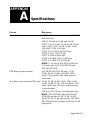
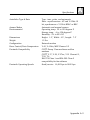
A: Specifications ....................................................... A-1
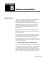
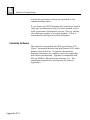
B: Software Compatibility ......................................... B-1
C: Facsimile Commands ...........................................C-1
D: Factory-Stored Profiles ........................................ D-1
E: ASCII Character/Decimal/Hex
Conversion Tables .................................................... E-1
F: Bit-Map Register Conversion Table ....................... F-1
G: Callback and Password Security ......................... G-1
H: Flash Memory Download ....................................H-1
vi
Z
About This Manual
Shown below is a chronological listing of revisions to
this manual. The revision sequence, date, and synopsis
of revised materials are included to provide the reader
with a comprehensive manual history.
REVISION NUMBER
18008-514A
DATE
09/98
DESCRIPTION
1st Edition
Zypcom welcomes your comments concerning this
manual. Although every effort has been made to keep it
free of errors, some do occasionally occur. When
reporting a specific problem or error, please describe it
briefly and include the manual name, the document
number, the paragraph or figure number, and the page
number.
Mail, phone in, or fax your comments to:
Zypcom, Inc.
2301 Industrial Parkway West, Bldg. 7
Hayward, CA 94545
Phone: (510) 783-2501
Fax: (510) 783-2414
Printed in U.S.A.
vii
Z
Warranty and Limitation of Liability
Zypcom, Inc. warrants that its products will perform in
accordance with Zypcom’s published specifications, for
a period of twenty-four (24) months from Zypcom's
original shipment date. For SX-Series modems, Zypcom
will, at no cost, promptly ship a replacement unit via
express courier within 24 hours on normal business
days for any equipment determined by Zypcom to be
defective (transportation charges prepaid by Zypcom) for
destinations within the continental United States. The
buyer will return defective SX-Series modem, prepaying
transportation charges via United Parcel Service. For
SE-Series modems the buyer will return defective
equipment, prepaying transportation charges via United
Parcel Service and Zypcom will return such equipment,
freight prepaid, using a like method. Warranty repair
on SX-Series and SE-Series modems for locations
outside the continental United States, the buyer will
return defective equipment, prepaying transportation
charges and Zypcom will return such equipment,
transportation charges prepaid via a method of its
choice. A repair number must accompany all returned
equipment (see “Service Information” later in this
section).
This warranty shall not apply to damage resulting from
abuse, negligence, accident, natural disaster (flood,
lightening, wind, etc.), loss, or damage in transit. The
warranty shall be voided should the Buyer attempt any
repairs or alterations without prior written permission
of Zypcom, Inc.
ZYPCOM MAKES NO OTHER WARRANTY, EXPRESSED
OR IMPLIED, AND DISCLAIMS ANY IMPLIED
WARRANTY OF MERCHANTABILITY OR FITNESS FOR A
PARTICULAR PURPOSE.
viii
Z
THE BUYER AND ZYPCOM AGREE THAT THE SOLE AND
EXCLUSIVE REMEDIES FOR BREACH OF ANY WARRANTY CONCERNING THE GOODS SHALL BE REPAIR OR
REPLACEMENT OF DEFECTIVE PARTS UPON THE TERMS
ABOVE DESCRIBED OR, AT ZYPCOM’S OPTION, REFUND
OF THE PURCHASE PRICE. ZYPCOM SHALL NOT BE
LIABLE FOR CONTINGENT OR CONSEQUENTIAL
DAMAGES TO PERSONS OR PROPERTY, AND ITS SOLE
LIABILITY IS AS SET FORTH ABOVE.
Any action by the Buyer for any alleged breach of the
warranty set forth herein shall be brought to the
attention of Zypcom, Inc. by the Buyer within the
warranty period, but not later than thirty (30) days after
the alleged breach.
THIS STATEMENT OF WARRANTY AND LIMITATION OF
LIABILITY IS A COMPLETE AND EXCLUSIVE STATEMENT
OF ALL WARRANTY AND LIABILITY REPRESENTATIONS
OF ZYPCOM, INC. It may not be varied, supplemented,
qualified or interpreted by any prior dealings between the
parties, or by any usage of the trade, or upon the face or
reverse of any form to which this is attached or is a part
of, nor may it be modified by any agent, employee or
representative of Zypcom unless such modification or
representation is made in writing and signed by an officer
of Zypcom, Inc.
Repairs and/or replacements under the terms of this
warranty SHALL NOT EXTEND THE WARRANTY LIFE OF
THE ORIGINAL EQUIPMENT SUPPLIED. After this
warranty has expired, service can be purchased directly
from Zypcom, Inc.
ix
Z
Service Information
In the event of malfunction or other indication of product
failure, please follow this procedure:
1. Call Zypcom Technical Support at (510) 783-2501,
Monday through Friday from 8:00 A.M. to 5:00 P.M.
Pacific time (excluding holidays).
2. Your support representative will ask you to perform a
few tests. If the tests do not solve the problem, you
will be issued a Repair Order (RO) number.
3. Return the unit in a protective shipping container and
send it prepaid to:
Repair Department
Reference: RO Number _______
Zypcom, Inc.
2301 Industrial Parkway West, Bldg. 7
Hayward, CA 94545
Please mark the shipping container with the RO number
and enclose a written description of the problem.
Terms
For warranty repair and/or replacements, the customer
pays freight charges incurred for sending the defective
modem to Zypcom. Zypcom pays freight charges for
sending repaired or replaced units. Warranty
replacements and/or repairs are performed at no charge to
the customer.
For non-warranty repairs, charges vary according to the
specific model of the modem being repaired. Repair
charges are estimated before an RO number is issued.
Customer prepays all freight and repair charges by means
of credit card or C.O.D. terms. Zypcom can accept
prepayment by company check.
x
Z
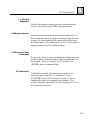
FCC Part 15: Radio/Television Interference
This equipment has been tested and found to comply with
the limits for a Class A digital device, pursuant to Part 15
of the FCC Rules. These limits are designed to provide
reasonable protection against harmful interference in a
residential installation. This equipment generates, uses
and can radiate radio frequency energy and, if not
installed and used in accordance with the instructions,
may cause harmful interference to radio communications.
However, there is no guarantee that interference will not
occur in a particular installation. If this equipment does
cause harmful interference to radio or television reception,
which can be determined by turning the equipment on,
the user is encouraged to try to correct the interference by
one or more of the following measures.
❑ Reorient or relocate the receiving antenna.
❑ Increase the separation between the equipment
and the receiver.
❑ Connect the equipment into an outlet on a circuit
different from that to which the receiver is
connected.
❑ Consult the dealer or an experienced radio/TV
technician for help.
CAUTION: Changes or modifications not expressly
approved by the party responsible for compliance could
void the user’s authority to operate the equipment.
CAUTION: Shielded interface cables, if any, must be
used in order to comply with emissions limits.
xi
Z
FCC Part 68: Requirements For End Users
Type of Service
Your modem can be used on standard telephone lines.
The modem connects to the telephone line with a
standard USOC RJ11C or RJ45S jack. Connection to
pay telephones is prohibited. Connection to party lines
service is subject to state tariffs.
Telephone Company
Procedures
The telephone company may occasionally make changes
in their equipment, operations, or procedures. They will
give you prior notice in writing, so you can make any
necessary changes to maintain uninterrupted service. If
you have any questions about your telephone line, call
the telephone company.
In certain circumstances, the telephone company may
request information concerning the equipment that you
have connected to your telephone line. Upon their
request, provide the FCC registration number and the
ringer equivalence number (REN) of the modem. Both of
these items are listed on the equipment label. The sum
of all of the RENs on your telephone line should be less
than five to ensure proper service from the telephone
company. In some cases, a REN sum of five may not be
usable on a given line.
When the modem is enclosed in a cabinet, a label listing
the unit’s registration number and ringer equivalence
number must be visible from the outside of the cabinet
or other enclosure, in addition to the label required on
the registered device itself. Additionally, OEMs must
provide their equipment, with the attached warnings, to
end users.
xii
Z
If Problems Arise
If your telephone equipment is not operating properly,
immediately remove it from your telephone line, as it
may cause harm to the telephone network. If the
telephone company notes a problem, they may temporarily discontinue service. When you are notified, you
will be given the opportunity to correct the problem and
will be informed of your right to file a complaint with the
FCC.
All repairs on your modem should be performed by
Zypcom, Inc. or an authorized representative of Zypcom,
Inc. For more information contact:
Customer Service
Zypcom, Inc.
2301 Industrial Parkway West, Bldg. 7
Hayward, CA 94545
(510) 783-2501
Statement of Fax Branding
The Telephone Consumer Protection Act of 1991 makes
it unlawful for any person to use a computer or other
electronic device to send any message via a telephone
fax machine unless the message clearly contains a
margin at the top or bottom of each transmitted page or
on the first page of the transmission; the date and time
the message is sent; an identification of the business,
other entity, or individual sending the message; and the
telephone number of the sending machine, business,
other entity, or individual.
xiii
Z
Canadian Department of Communications—
Requirements For End Users
The Canadian Department of Communications label
identifies certified equipment. This certification means
that the equipment meets certain telecommunications
network requirements. The Department does not
guarantee the equipment will operate to the user’s
satisfaction.
Before installing this equipment, the user should ensure
that connection to the line is allowed by the local
telecommunications company. The equipment must
also be installed by using an acceptable method of
connection. In some cases, the company’s inside
wiring, associated with a single-line individual service,
may be extended by means of a telephone extension
cord. Compliance with the above conditions may not
prevent degradation of service in certain situations.
Equipment repairs should be made by an authorized
Canadian maintenance facility designated by Zypcom,
Inc. Any repairs or alterations made by the user may
cause the telecommunications company to request
disconnection.
The electrical ground connections of the power utility,
telephone lines, and internal metallic water pipe system,
if present, should be connected together. This
precaution may be particularly important in rural areas.
CAUTION: Users should not attempt to make such
connections themselves, but should contact the
appropriate electrical inspection authority, or
electrician, as appropriate.
xiv
Z
The Load Number (LN) assigned to each terminal device
indicates the total load percentage that can be connected to a telephone loop. The termination on a loop
may consist of any combination of devices. However,
the total LN of all the devices must not exceed 100.
The Load Number and Canadian certification number
are listed on the modem label. The Canadian DOC
connector codes supported are CA11A, CA41A, and
CA45A. For internal modems on which the agency
information label cannot be seen when the modem is
installed, a second agency label will be provided. The
customer must attach the label to the exterior of the
cabinet in which the modem is installed.
Repairs
Inquiries regarding Canadian repair centers should be
addressed to:
Customer Service
Zypcom, Inc.
2301 Industrial Parkway West, Bldg. 7
Hayward, CA 94545
(510) 783-2501
xv
Z
xvi
CHAPTER
1
Introduction
Description
T
he Zypcom SX-Series and SE-Series are
versatile, very high-speed, asynchronous/
synchronous modems that allow data and
facsimile transmission between your local PC or host
computer and other remote host computers, networks
(LANs), or facsimile machines. The Z34-SE, Z32t-SE and
Z32b-SE can operate in full- or half-duplex (simulated
with V.13) on dial-up or on two-wire leased lines, and
feature a variety of compatibilities and capabilities. The
Z34-SX, Z32t-SX and Z32b-SX can operate in full- or
half-duplex (simulated with V.13) on dial-up, two-wire
or four-wire leased lines, and feature a variety of
compatibilities and capabilities. In this manual, any
differences among the six modems (Z34-SX, Z32t-SX,
Z32b-SX, Z34-SE, Z32t-SE and Z32b-SE) are explained.
Features
❑
❑
❑
❑
External modem
230,400 bps to 300 bps DTE operation (Z32t-Sx,
Z32t-SE, Z32b-SX, Z32b-SE max. speed is
115,200 bps)
Z34-SX and Z34-SE are software upgradeable via
flash memory
Z34-SX and Z34-SE supports line rates from
33,600 bps to 300 bps compatible with V.34+,
V.34, V.32terbo, V.32bis, V.32, V.22bis, V.22,
V.23, 212A/103, V.21, and Group 3 fax
1–1
1
Introduction
❑
❑
❑
❑
❑
❑
❑
❑
❑
❑
❑
❑
❑
❑
❑
1–2
Z32t-SX and Z32t-SE supports line rates from
19,200 bps to 300 bps compatible with
V.32terbo, V.32bis, V.32, V.22bis, V.22, V.23,
212A/103, V.21, and Group 3 fax
Z32b-SX and Z32b-SE supports line rates from
14,400 bps to 300 bps compatible with V.32bis,
V.32, V.22bis, V.22, V.23, 212A/103, V.21, and
Group 3 fax
Asynchronous and synchronous full- and halfduplex operation (HDX simulated with V.13
switched carrier)
Hayes AT autodialing and Dial-on-DTR
V.25bis asynchronous and synchronous
autodialing
CCITT V.42 and MNP Class 2-4 error control
CCITT V.42bis and MNP 5 data compression for
throughput up to 195,000 bps on the Z34-SX/
Z34-SE and 125,000 bps on the Z32t-SX/Z32tSE
Class 1 and 2 facsimile command compatibility
with Group III fax machines at 14.4 Kbps (V.17),
9600 bps (V.29), and 4800 bps (V.27ter)
SX-Series have two-wire dial-up and two-wire/
four-wire leased line operation with autodial
backup and auto-restoral
SE-Series have two-wire dial-up and two-wire
leased line operation with autodial backup and
auto-restoral
Remote modem control and security
10 number callback security and Zscript autologon
Prestored modem configurations for popular
applications
Memory and configuration security
Automatic speed conversion and eight types of
flow control
Introduction
❑
❑
❑
❑
❑
❑
1
V.54 diagnostics and V.13 switched carrier
Nonvolatile memory for storing up to four
telephone numbers and logon sequences
Manual and automatic dialing and answering
Built-in diagnostics that let you test the entire
communications link
Caller I.D. supported
Hardware DIP switches for manual operation
Functional Capabilities
The Zypcom modem with its state-of-the-art technology
adds unmatched versatility to your data
communications network. The modem operates with
any computer terminal that uses 8 to 11-bit ASCII
characters and has a serial port. Since these two
standards are well established, you can connect your
Zypcom modem to most applications requiring data
communication.
The SX-Series and SE-Series are compatible with the
Hayes AT command set and with communications
software that employs the AT command set. In
addition, Zypcom modems support asynchronous and
synchronous versions of the V.25bis autodialer. This
autodialer works well with computers such as the IBM
AS/400 and with bridge/router products, which provide
V.25bis autodialing capability for dial backup of
dedicated WAN links or bandwidth on demand.
Zypcom modems will suit most styles of data
communication. It provides high-speed connectivity for
IBM PCs and compatibles, Macintosh computers, and
UNIX workstations. It also supports facsimile
transmission in conjunction with EIA 578/592 Class 1or 2-compatible fax software, as well as synchronous
dialing for dial-up minicomputer communications. The
SX-Series can operate on four-wire leased lines with dial
1–3
1
Introduction
backup and automatic restoral for multiplexer or router
links. The SE-Series can operate on two-wire leased
lines with dial backup and automatic restoral for remote
PC's and terminals.
These modems also support full manual operation:
connect the telephone, pick up the handset, dial the
number, and press the <DATA> key on the
multifunctional front panel. All the advanced functions
you need can be viewed from the indicator lights. In
addition, the modems support fully automatic “hands
off” operation, putting unmatched flexibility and
performance into your dial-up and leased line
communication links.
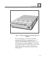
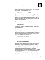
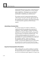
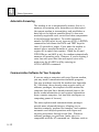
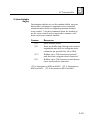
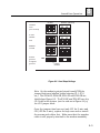
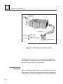
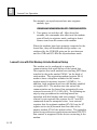
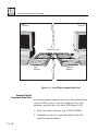
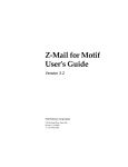
Physical Capabilities
The SX-Series and SE-Series are external modems.
Operator inputs are through the serial port using the AT
or V.25bis command sets. Additionally, operations such
as redialing from memory location 0, complete resetting
of modem options and memory, forcing of EIA options,
testing, and manual dialing/answering can be
performed from the front panel. The operation of the
modem and DTE can be monitored using the extensive
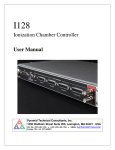
LED display (see Figure 1-1).
1–4
Introduction
TXD RX
D CTS
DSR DT
R CXR
Z32b-S
X
FULL DU
PLEX
EC
AA
1
SYN SP
D FAX
DATA
V.32bis
/V.42bi
s/FAX
TEST
ZYPCO
M
Z32b-SX.1.1
Figure 1.1.
Figure 1-1. SX-Series and SE-Series Front-Panel Controls and
Indicators
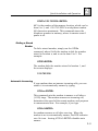
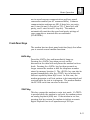
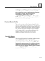
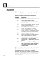
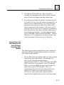
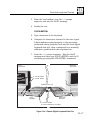
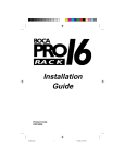
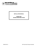
The rear panel (figure 1-2) contains a 6-pin PSTN
connector labeled “WALL,” a 6-pin telephone set and
leased line connector labeled “PHONE,” a power
connector labeled “POWER,” and a serial port connector
for the DTE interface labeled “TERMINAL.” On the side
of the modem is a power ON/OFF rocker switch. On the
underside of the unit is a 10-position DIP switch for
manual control of the modem and a knob for manual
volume control.
1–5
1
Introduction
WALL
POWER
PHONE
AL
TERMIN
Z32b-SX.1.2
Figure 1.2.
Figure 1-2. SX-Series and SE-Series Rear Panel
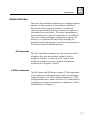
Specifications
The SX-Series and SE-Series product specifications are
listed in Appendix A.
1–6
Introduction
1
Options Selection
There are four methods of selecting or changing modem
options. A large portion of this manual consists of
descriptions for using each method. You should
concern yourself only with the sections that pertain to
the method you’ve selected. The most comprehensive
and easiest to use is the AT command set. In addition,
there are V.25bis autodialer commands to option the
modem, a 10-position DIP switch for changing the
modem’s functional operation, and the front-panel keys
for limited control of modem options.
AT Commands
The AT-compatible command set can be used to select
telephone line type and modem options, to dial a
telephone number, to hang up a call, and to store
telephone numbers and user profiles into memory
locations (see Chapters 5 and 6).
V.25bis Commands
The SX-Series and SE-Series support V.25bis operation
of the modem in both synchronous and asynchronous
communication. A V.25bis command extension—CNL
(configuration local)—allows access to AT commands for
configuring, viewing, and testing the modem in V.25bis
autodialing (see Chapter 7).
1–7
1
Introduction
Front-Panel Keys
and DIP Switch
The front-panel <DATA> and <TEST> keys and the DIP
switch on the modem control a variety of modem
options. Using these keys and switch is simple and
straightforward and requires little technical experience.
However, the keys do not allow full control of modem
features.
Software Programs
An extensive variety of communications software is
already available, but advanced computer users can
write their own software programs to interact with SESeries memory, selecting options using either AT or
V.25bis commands. The SX-Series and SE-Series are
an EIA 578/592 Class 1- and 2-compatible device that
will work with any off-the-shelf fax communications
program that supports Class 1 or 2 fax commands.
However, software programming methods for option
selection in data or fax modes are not discussed in this
manual. If you don’t already own data communications
or facsimile software, you should purchase the packages
already preconfigured for the SX-Series or SE-Series
modems (see Appendix B).
Quick Startup Procedure
A quick startup procedure in Chapter 2 provides
information for quickly getting your SX-Series and SESeries modems on-line. Otherwise, refer to Chapters 4,
5 and 6 for complete information about installation and
the Hayes AT command set.
1–8
Introduction
1
How to Use This Manual
This manual contains operating instructions for the SXSeries and SE-Series of modems. Most users will be
using the modem on a personal computer or
workstation running communications software in
asynchronous data format. Appendix B discusses
communications software compatibility. Carefully read
through that information before proceeding with your
installation, as it will provide you with a basic
understanding of the modem’s requirements and
operation. For those using synchronous
communication, you’ll find the essential information in
Chapters 7 and 8. When using the SX-Series and SESeries in asynchronous communication, you’ll probably
find it useful to review the details and operating
instructions in Chapters 4, 5 and 6.
Conventions
In this manual, the < > symbols are used to designate
the name of a key on the modem or on your computer
or terminal keyboard. For example, when you see
<ENTER>, it means press the ENTER key. Bold
characters are used to specify a command sequence
sent to the modem. For example, an instruction to dial
a telephone number would appear like this:
type ATDT9,510 783 2538 <ENTER>
1–9
1
1–10
Introduction
CHAPTER
2
Quick Installation
and Operation
Introduction
T
he Zypcom external modem has many powerful
features for mission critical corporate networks.
The more you know about your modem, the more
you can do with it. But like most people, you are
probably anxious to get your modem on-line as soon as
possible and will consult the manual only as necessary.
This chapter, therefore, contains only the information
you’ll need to get the modem up and running on an
asynchronous dial-up communication link.
You’ll learn about the communication software you
might need, how to connect the modem to your terminal
or computer, and how to run basic tests. You’ll also be
presented with some setup tips, dialing commands, and
other ready information. Once the modem is
operational, you can browse through the rest of the
manual at your leisure.
Your Data Terminal Equipment
Before beginning the installation, you must first
determine what kind of communications connector your
data terminal equipment (DTE) has. Most likely your
DTE will be a terminal, PC or workstation. Consult the
manual that came with your DTE or look on the back
panel to determine what kind of communications
interface is there. Terminals are generally outfitted with
a serial interface port and do not require any special
2–1
2
Quick Installation and Operation
interface software. Most desktop computers are
equipped with one, but if yours isn’t, you might have to
purchase an asynchronous communications or serial
card. This is a circuit board that fits into a slot on your
computer’s internal bus. It should have a connector to
which you can attach a cable for a serial printer,
modem, or other device.
An interface cable is not supplied with the modem
because different computers have different interface
connectors. You can buy a pre-wired serial cable
(normally called a modem cable) from a computer store.
There are cables for many common computers. A
shielded cable should be used with the modem to
maintain FCC Class B operation. The cable end that
connects to your computer should have whatever
connector—DB25, DB9 or DIN—is suitable for that
equipment. The end that connects to the modem
should terminate in a male DB25-type connector. Cable
length should not exceed 50 feet.
PC Software for Modem Communication
Terminals don’t usually require communications
software, but most personal computers and workstations do. Brands such as Netscape, Explorer,
Carbon Copy, COMit, Crosstalk, PROCOMM, QModem,
Windows Hyperterminal and many others are based on
the AT command set and are supported by the SXSeries and SE-Series modems. Most of them can
emulate different terminals and let you issue AT
commands directly from the keyboard, but you can also
place the modem entirely under the control of the
communications software for more “transparent”
operation.
2–2
Quick Installation and Operation
2
For the operation you require, consult the installation
procedure for the communications software you have
chosen. If your software doesn’t have a Zypcom modem
listed in the modem setup menu, try the following
initialization string for a standard async dial-up
application. Select your modem type as CUSTOM or
OTHER, whichever is available to you that allows for a
your own initialization sequence, and enter this
command string:
AT&F0&C1&D2&S1&K3&Q6S7=90S0=0&W<ENTER>
If this command string doesn't work try inserting the
following commands E0Q0V1 to the above string right
after the S0=0 but before the &W.
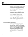
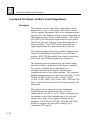
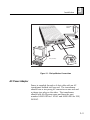
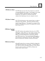
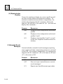
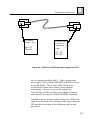
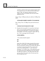
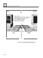
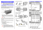
Modem Connections
Detailed installation instructions are found in Chapter
3. For quick dial-up line setup, refer to figure 2-1 and
follow these easy steps:
1. Plug one end of the included modular phone cable
(part no. 15047-004) into the jack marked “WALL”
on the back of the modem. Plug the other end into
the telephone wall jack of your home or office.
2. Plug the end of the serial cable terminating in the
25-pin male connector to the modem port marked
“TERMINAL.” Plug the end of the cable outfitted for
your particular computer or terminal into its
connector. (This cable is not supplied with the
modem.)
3. Plug the small end of the power adapter into the
socket marked “POWER” on the modem. Plug the
transformer end into a 110 VAC outlet and turn on
the modem’s power switch (located on the side).
2–3
2
Quick Installation and Operation
4. Optionally, you may plug a standard telephone into
the jack marked “PHONE” on the back of the
modem. This will allow you to talk over the
telephone line without having to unplug the modem
or install another wall jack. With a telephone
connected, you can dial and answer and place voice
calls manually. The telephone works in a normal
fashion, even when the modem is turned off.
to PC (RS-232)
(Optional)
to
telephone
walljack
TXD RX
D CTS
DSR DTR
CXR
Z32b-SX
FULL DU
EC
AA
PLEX V.3
2bis/V.4
2 bis/FAX
SYN SPD
FAX
DATA
TEST
ZYPCOM
to
110 VAC
outlet
Z32b-SX.2.1
Figure 2.1.
Figure 2-1. Connecting the SX-Series and SE-Series
2–4
Quick Installation and Operation
2
Computer/Terminal Setup
For existing applications, all you need to do is change
the speed of your DTE to 230,400, 115,200, 57,600 or
38,400 bps, whichever is the highest speed supported
by your DTE. For new applications, set your DTE’s data
bits per character (usually 8) and parity (usually no
parity) to whatever is required by the remote connection
and set flow control to RTS/CTS (hardware).
Powering Up and Checking Out Your Modem
Turn on your computer and modem. If any LED flashes
frequently, refer to Chapter 10, "Troubleshooting and
Testing." A quick way to ensure that your modem and
most of its critical components are functional is to
perform an analog loopback (ALB) data test, which
checks the modem's transmitter, receiver, and interface
to the DTE. The modem will perform this test with or
without speed conversion if you are using the keyboard
of a DTE. To start the ALB data test, type:
AT&T1<Enter>
The modem responds with a CONNECT XXXX message,
where XXXX varies according to the setting of the Wn
and Nn commands and register S37=nn. During an
ALB test, characters you type from the keyboard go to
the modem and are sent back to the DTE screen. If
correctly modulated and demodulated, the same
characters you type will appear on the screen. If a
problem occurs during modulation and demodulation or
on the interface to the DTE, characters different from
what you typed will appear. In this case, refer to
Chapter 3, "Installation," and Chapter 10,
"Troubleshooting and Testing."
2–5
2
Quick Installation and Operation
To exit an ALB test, type:
+++
Wait for the OK message and then type:
AT&T0<ENTER>
Wait for the OK message. If the ALB data test was
successful, then the modem is functioning normally and
you can proceed with using the modem for dialing.
This checkout procedure assumes your communications
software can allow terminal emulation so that direct
communication with the serial port of the modem is
possible.
Dialing
Dialing From a
Computer or
Terminal
You can dial a number from your computer or terminal
keyboard. If you are a PC user and have not already
done so, begin by loading your communications
software. Before entering terminal emulation mode, set
your software (or DTE) for its highest speed and select
RTS/CTS (hardware) flow control. The modem supports
serial port speeds from 230.4Kbps to 300 bps. If this is
your first time communicating, make sure your data
bits and parity are also set correctly. If you do not
know how to invoke the terminal emulation mode, refer
to the documentation for your communications
software.
With the communications software (or DTE) in terminal
emulation mode, type:
2–6
AT <ENTER>
Quick Installation and Operation
2
If the PC or terminal is correctly set up, you will get an
OK message. To begin dialing, type:
ATDT telephone number <ENTER>
The modem dials the number you entered. The AT in
the above commands means “attention.” This alerts the
modem that more commands are on the way. The D is
the dial command, and the T following the D forces the
modem into tone dialing.
To automatically redial the number, type:
ATDL <ENTER>
The modem retrieves the number from its “dialed last”
buffer and dials it.
Note that you can enter commands in either lower- or
uppercase. It is not necessary to enter spaces or
punctuation, but you are permitted to do so as they are
ignored. For example, if you wanted to call (510) 7832538, the format would typically be:
ATDT 1 510 783 2538<ENTER>
or
atdt 1 510 783 2538<ENTER>
If you are calling another modem, you’ll hear it answer
through the internal speaker on the modem. It will
send a high-pitched tone to which the modem responds
with a like tone. During this handshaking, the highest
common speed is detected unless the modem is
configured to force a selected speed (by means of N0 and
the setting of register S37). The speaker turns off, and
a CONNECT XXXX message appears on the terminal or
computer screen. You can obtain additional messages
that tell you the error control, data compression, and
2–7
2
Quick Installation and Operation
port speed status by entering an ATW1 command prior
to dialing. You can dial telephone numbers of any
combination of characters, to a maximum of 68
characters, including digits 0 through 9, *, #, A, B, C,
D, and dial modifiers (,), @, !, ;, W, R, T, and P.
You can adjust the speaker volume by turning the
volume control knob on the bottom of the modem.
Dialing From a
Telephone
To manually dial a number, insert a telephone Tadapter in-line with the telco cable and install a
telephone in the extra opening. Pick up the telephone’s
handset, listen for dial tone, dial the telephone number,
press the <DATA> key on the modem’s front panel
immediately after dialing the telephone number, and
quickly return the telephone handset to the cradle. If
the handset isn't returned to the cradle quickly, it can
cause a faulty handshake to occur. The modem will
connect to the remote modem and issue a CONNECT XXXX
message to the DTE, where XXXX equals the speed of
the last autobaud. Note that when you first unpack
your modem, it is set for autobaud at 230,400 bps. If
your DTE doesn’t support 230,400 bps, you must send
the AT<ENTER> command to the modem so that it can
match the speed you’ve selected for your DTE, or you
must use the %X command to set a new speed before
manually dialing a call.
Storing a Telephone
Number
You can store a maximum of four telephone numbers in
nonvolatile memory unless the security feature (S34=0)
is in use then you can store 10 numbers. For example,
to store a telephone in memory location 1, type:
2–8
Quick Installation and Operation
2
AT&Z1=1 510 783 2538 <ENTER>
&Z1 is the number of the memory location, which can be
from 0 to 3, and 1 510 783 2538 is a telephone number
(68 characters maximum). This command stores the
telephone number in memory, where it remains even if
power is off.
Dialing a Stored
Number
To dial a stored number, simply use the ATDSn
command, where S tells the modem to dial the number
stored in location n, and n can be from 0 to 3. For
example:
ATDS1<ENTER>
The modem dials the number stored in location 1, and
the screen displays:
1 510 783 2538
Automatic Answering
If your modem does not answer incoming calls, you can
enable it to automatically answer by typing:
ATS0=n <ENTER>
This command sets the modem to answer a call after n
(1-255) rings. The modem answers an incoming call,
determines the speed of the remote modem, and prepares
to communicate data. For example, if you type
ATS0=1<ENTER>
the modem answers a call after one ring. When the
modem is set to automatically answer, the LED indicator
over AA is on. Issuing ATS0=0<ENTER> disables auto
answer.
2–9
2
Quick Installation and Operation
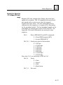
Line Speed, Port Speed, and Error Control Negotiations
Line Speed
The modem can have three basic types of line speed
negotiations. Type 1, the default, (S37=0N1) is where
the line speed negotiations start at the maximum speed
supported by the modem and can go lower depending on
the maximum speed of the remote modem. With Type 2
(S37=nnN1) the line speed negotiations start at speed
selected by the user and goes lower depending on the
remote modem. Type 3 (S37=nnN0) forces the line
speed negotiations to a speed selected by the user.
The modem supports many line speeds; therefore, flow
control should always be enabled on your DTE and
modem. RTS/CTS (hardware) flow control is preferred
when both your DTE and modem can support it.
The modem operates automatically (in default mode)
and will attempt to send data at the highest possible
line speed. In default mode the modem will
automatically match the highest common data
transmission rate of the remote modem. The sequence
of data transmission rates it will seek is 33,600, 31,200,
28,800, 26,400, 24,000, 21,600, 19,200, 16,800,
14,400, 12,000, 9600, 7200, 4800, 2400, 1200 and 300
bps, no matter what the speed of the last autobaud (AT
command).
The modem can be optioned to start handshake
negotiations at the speed selected by you with
commands N1 and S37=1 to 36. These commands tell
the modem to start the handshaking at the selected
speed and connect at the highest common speed
available. The Z32t-SX, Z32t-SE, Z32b-SX and Z32bSE do not support the line speed ceiling Type 2
commands (S37=nnN1).
2–10
Quick Installation and Operation
2
In addition, the modem can be optioned to force a
particular line speed with the N0 command and with
S37 set to equal a desired line speed. These commands
tell the modem to connect only at the speed of register
S37.
Serial Port Speed
The modem has asynchronous speed conversion (&Bn)
that will automatically convert the modem line speed to
match the DTE’s, based on the speed of the last AT
command. In its default setting (&B1), the modem
converts from the last autobaud (set at the factory to
115,200 bps) to the line speed of the modem to which it
connects.
Error Control (EC)
Negotiations
The &Qn command controls how the modem negotiates
an error controlled link. In its default setting, the
modem automatically attempts the highest possible
error control level. The priority is V.42 first, MNP
second, and normal buffered asynchronous operation
third. The default setting (&Q6) causes the modem to
first attempt a V.42 negotiation. If that fails, an MNP
negotiation is attempted. If that fails, the modem
establishes a buffered asynchronous link. The &Q5
command eliminates the V.42 negotiation and attempts
an MNP negotiation first. If that fails, it establishes
normal buffered asynchronous operation. The &Q7
command eliminates the MNP negotiation. If that fails,
it establishes normal buffered asynchronous operation.
&Q0 establishes a normal buffered asynchronous
operation.
2–11
2
Quick Installation and Operation
When communicating with lots of different types of
modems, it is important to understand how the line
speed, port speed, and error control negotiations occur
in the modem. Select the line speed, port speed, and
error control negotiations required for your application;
you can then begin using the modem.
The modem monitors the condition of the phone line at
initial handshake and during the call to ensure that
data can be sent with few errors at the fastest speed. If
it senses that data integrity could be compromised by
line conditions, it will fall back to the next lower
transmission rate. The modem will negotiate a higher
data transmission rate when conditions improve.
Testing the Modem
The modem performs an automatic self-test whenever
power is applied and the modem is in idle mode (not
transmitting or receiving). This procedure ensures
proper operation of the modem’s major components. If
the modem fails the self-test, it will busy the telephone
line out and will flash the FAX LED.
After following the connection procedure and applying
power (remember to flip the ON/OFF switch on the
side), look at the front panel of the modem. If any LED
flashes, the modem has failed self-test and will not
operate correctly. If this happens regularly, contact
Zypcom Customer Service, listed in the front of this
manual.
2–12
CHAPTER
3
Installation
Unpacking
T
he SX-Series and SE-Series modem box comes
with a modem, a manual, a detachable telephone
cord and an AC power adapter. Depending on
the model you ordered, your modem could include fax
and data communications software. Check that the
package agrees with the number and type of items
included: User Guide, telephone cable (15047-004),
power transformer (110V is P/N 94200-090 and 220/
240V is 94200-092) and a modem. The serial cable that
connects the modem to the computer or terminal must
be supplied separately. Check with your dealer for the
correct interface cable for the computer or terminal you
are using. Normally, a modem cable will include pins 1
through 8, as well as pins 15, 17, 20, and 22. You can
also make your own interface cable based on the pinout
information supplied in table 3-1.
Inspect the modem and power adapter to make sure
that neither has been damaged. Also look at the carton.
If the carton is heavily damaged, the modem may be
damaged as well. Return the box and modem to your
dealer or shipping carrier if you suspect any damage.
Inspect your option packages closely for damage. If
damage is detected, return the merchandise to your
dealer.
3–1
3
Installation
Site Selection
Place the modem so that its cables reach the telephone
wall jack, the power adapter, and your computer or
terminal. There should be no strain on the cables.
Allow at least four inches of space behind the modem to
accommodate cables and permit airflow.
Install the modem close to your computer or terminal so
that you can easily reach the controls on the modem’s
front and underside.
Do not obstruct the cooling vents on the top or bottom
of the modem and make sure the modem never gets
warmer than 50°C (122°F) or cooler than 0°C (32°F)
when in use. Do not expose it to excessive humidity,
shock, vibration or electromagnetic interference (EMI).
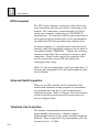
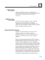
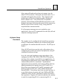
Connecting the Modem
This section shows how to connect the modem to the AC
power transformer, telephone line, and to the computer,
terminal or other data terminal equipment (DTE) device
with a serial port.
Before connecting the modem, make sure the power
switch located on the side of the modem is in the off
position (rocker switch down).
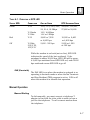
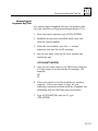
Figure 3-1 shows the back of the modem and the
connections that go to it. Refer to this figure when
following procedures in this section.
3–2
Installation
3
to
110 VAC
outlet
to
telephone
walljack
WALL
POWER
PHONE
to PC (RS-232)
Z32b-SX.3.1
Figure 3.1.
Figure 3-1. Dial-up Modem Connections
AC Power Adapter
Power is supplied through a 6-foot cable with an AC
transformer molded into one end. The transformer
should have a two-prong AC connector on one end and
a phono-type plug on the other. The transformer
should bear the Zypcom name and have the part
number 94200-090 for 110VAC and 94200-092 for 220/
240VAC.
3–3
3
Installation
DTE Connection
The DTE is the computer, terminal or other device having a serial data port that you will be connecting to the
modem. The connection is made through a 25-pin Dseries type connector conforming to V.24/RS232-D
specifications. The interface cable for this connection is
not supplied with the modem but can be purchased for
your particular DTE through almost any computer store.
As shown in figure 3-1, plug the male connector of the
interface cable into the female connector on the back of
the modem labeled “TERMINAL.” Tighten the retaining
screws on each side of the connector to ensure a good
connection. Plug the other end of the interface cable
into the serial port of your DTE and tighten the
retaining screws, if any.
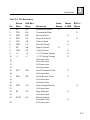
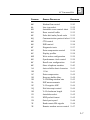
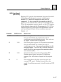
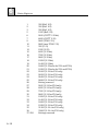
Table 3-1 lists the assignment of each pin and table 3-2
lists the pin assignment of the wall and telephone jacks
on the modem.
Strap and Switch Inspection
There are ten DIP switches on the underside of the
modem and hardware straps (jumpers) on the modem
circuit board that may have to be changed before
installation begins. Refer to Chapter 4 for the locations
of these switches and straps and for instructions on
how to configure them.
Telephone Line Connection
The modem accommodates permissive and
programmable connections. It doesn’t support
programmable service on the public switched telephone
network. When connected to a programmable jack, the
transmit level is −10 dBm.
3–4
3
Installation
TABLE 3-1. PIN ASSIGNMENTS
PIN
1
2
3
4
5
6
7
8
9
10
11
12
13
14
15
16
17
18
19
20
21
22
23
24
25
ZYPCOM
DESIG.
EIA/BELL
DESIG.
FG
TXD
RXD
RTS
CTS
DSR
SG
CXR
+V
-V
AA
BA
BB
CA
CB
CC
AB
CF
+P
-P
SCT
DB
SCR
DB
DTR
CD
RI
CE
SCTE
DA
DESCRIPTION
Protective Ground
Transmitted Data
Received Data
Request to Send
Clear to Send
Data Set Ready
Signal Ground
Carrier Detect
+12 V Testing Voltage
-12 V Testing Voltage
No Connection
No Connection
No Connection
No Connection
Serial Transmit Clock
No Connection
Serial Receive Clock
No Connection
No Connection
Data Terminal Ready
No Connection
Ring Indicator
No Connection
External Serial
Transmit Clock
No Connection
SIGNAL
GROUND
MODEM
DTE
TO
DTE TO
MODEM
X
X
X
X
X
X
X
X
X
X
X
X
X
X
X
3–5
3
Installation
TABLE 3-2. TELEPHONE LINE INTERFACE (AT REAR OF MODEM OR ADAPTER 15080-001)
PERMISSIVE
MODEM JACK LABELED
CONNECTION
WALL—PIN NO.
Permissive RJ11C
1
voice jack to modem
2
wall jack (from rear,
3
read pins left to right)
4
5
6
2-WIRE LEASED LINE
MODEM JACK LABELED
CONNECTION
PHONE—PIN NO.
2-wire Leased Line
1
RJ11C to modem
2
phone jack. Hard3
ware straps
4
must be set to enable
5
2-wire leased line (from
6
rear, read pins leftto right)
4-WIRE LEASED LINE
15080-001 JACK LABELED
ADAPTER CONNECTION
LINE—PIN NO.
4-wire Leased Line
1
Requires optional adapter
P/N 15080-001 installed
2
into modem phone jack.
3
Hardware straps must be
4
set to enable 4-wire
5
leased line (from line side
6
of 15080-001 adapter read
pins from left to right)
COLOR
Brown
Yellow
Green
Red
Black
Orange
SIGNAL
No Connection
MIC
Ring
Tip
MI
No Connection
COLOR
Brown
Yellow
Green
Red
Black
Orange
SIGNAL
No Connection
No Connection
No Connection
No Connection
2-wire TX(Tip)
2-wire RX(Ring)
COLOR
Brown
15080-001
SIGNAL
No Connection
Yellow
Green
Red
Black
Orange
4-wire RX
4-wire TX
4-wire TXC
4-wire RXC
No Connection
Permissive
Connection
Most homes and offices use the two-wire dial-up line
called a “permissive” connection, where a cord
terminated with a modular 6-pin plug carries the
3–6
Installation
3
signals from the modem to the wall jack. This is the
simplest type of connection and is used on most
standard telephones. The modem transmits over this
type of line at a fixed level of -10dBm ± 1dB. Signal loss
between the modem and the central office is not
controlled in permissive connections.
Permissive cables terminate in modular 6-pin RJ11Ctype plugs that can fit into RJ11C, RJ12C, RJ13C,
RJ16X, RJ41S or RJ45S wall jacks. Supplied with the
modem is a 7-foot cable (Zypcom part no. 15047-004)
with an RJ11C plug on each end.
Plug one end of the 7-foot cable into the jack marked
“WALL” on the back of the modem. Plug the other end
into the wall jack normally used for a telephone.
You can use the wall jack for both the modem and a
phone by connecting the modem to the wall jack as
directed above and plugging the telephone into the jack
marked “PHONE” on the back of the modem. This
allows you to use the phone for voice communication
whenever the modem is not in use.
Do not interrupt the data connection with voice communication. Voice communication destroys the flow of
data, causing errors. Sometimes it can force the
modem to break the connection. Picking up any other
telephone connected to the same telephone line, such
as an extension telephone, can cause data errors.
The interrupt signal from the telephone company can
break the connection or cause errors in the data. Turn
off call waiting, if possible. If not, consider canceling
the feature or installing a second telephone line.
3–7
3
Installation
Programmable
Connection
A programmable connection corrects for the signal loss
between the modem and the PSTN central office. The
loss is compensated by boosting the modem’s
transmission level to ensure that a −12 dBm signal
reaches the telephone company’s central office. The
modem will accommodate this type of connection but
will not boost the transmission level beyond −10 dBm.
2-Wire Leased Line
Connection
Leased lines (private lines) are installed at your site by
the phone company and must be the two-wire type
connection. A 2-wire leased line cable which conforms
to the pinout information on Table 3-2, 2-wire Leased
Line (PHONE connector, pins 5 and 6) can sourced
locally, or call the factory to purchase the optional 2wire leased line cable (91009-202).
4-Wire Leased Line
Connection
Only the SX-Series (Z34-SX, Z32t-SX, Z32b-SX)
modems will operate on 4-wire leased lines. A 4-wire
leased connection requires the use of adapter P/N
15080-001. This required adapter comes with two
additional cables (P/N 91009-105 a modular-to-spade
lug cable, P/N 15080-002 a modular RJ11-to-RJ45
cable), one of which will be required to complete the
connection to the 4-wire leased line termination point.
Plug the modem side of the 15080-001 adapter into the
modem jack labelled PHONE. The line side pinouts are
listed on Table 3-2, 4-wire Leased Line.
3–8
Installation
3
Powering Up
Turn the modem and the computer equipment on. As
the modem powers up, it will start a self-test diagnostic.
The modem will continually flash one of several LED's if
errors occur. Regular occurrence of LED flashes while
the modem is powering up while on-hook indicates a
problem (refer to Chapter 10). In addition, the modem
will can power up with the FAX LED on which indicates
that the FLASH memory failed to load properly. Cycle the
modems power several times, if the problem continues
return your modem to your reseller.
Upon power up with default options (&F0), you should
see the CTS, DSR, CXR, and AA LEDs on. If the LEDs do
not turn on, then recheck your AC power cord and serial
cables to ensure solid connections. If you still have a
problem, then reset the modem by pressing <DATA> and
<TEST> while cycling power.
Checking Your Connections
There are several quick steps that you can follow to
ensure that your modem and computer are properly
connected to the telephone network.
Checking the
Telephone Line
Press the <DATA> key momentarily and then release it.
The modem will go off-hook and connect you to the
telephone line. You should hear a dialtone from the
modem’s speaker even on a PBX line. If you don’t hear
dialtone, your line is probably not active and you need to
change to another line. Once you hear dialtone, you can
be assured that you have a good line. Press the <DATA>
key again and the modem will go back on-hook.
3–9
3
Installation
Checking Your
Computer to Modem
Link
To check the asynchronous link between the DTE and
modem, you must set up your DTE’s communication
parameters, the most important of which are data type,
speed, character length, parity and flow control. Match
the requirements of the remote computer or use these
settings for installation checkout: DTE speed = 115,200
bps, character length = 8 bits, parity = none, stop bits =
1, and flow control = RTS/CTS (hardware).
If these settings don’t work, refer to Chapter 5 and reset
them to conform with your application.
Once you have set the communication parameters,
enter terminal emulation mode if using a PC and from
your keyboard, type:
AT<ENTER>
The modem should respond with an OK message. If it
doesn’t, you may have encountered a common problem
(see section entitled, Common Problems and Solutions).
On the other hand, if you receive the OK message, your
computer to modem link is working.
Checking Your Modem
A quick way to ensure that your modem is functioning
properly is to perform a diagnostic called an analog
loopback (ALB) data test. To start this test, type:
AT&T1<ENTER>
After several seconds, the modem responds with
CONNECT XXXX (where XXXX equals the speed), which
indicates the modem has entered test mode. Now send
3–10
Installation
3
data from your DTE keyboard. What you send to the
modem should be echoed back to the DTE screen if your
modem is working properly. If the modem passes this
test, you can begin using it with confidence. To exit
ALB, type:
+++
Wait for the OK message and then type:
AT&T0<ENTER>
Wait for the second OK message. You are now back in
command mode and the modem may be used for
dialing.
If the modem didn’t perform the ALB data test correctly,
then there is probably a simple problem that needs
correcting. Review “Common Problems and Solutions”
first. If that doesn’t correct the problem, then refer to
the chapter on diagnostics.
Common Problems and Solutions
Problems
During setup and checkout, several areas are cause for
making the modem function improperly.
1. Your communications software doesn’t have
terminal emulation mode with which to check the
modem.
3–11
3
Installation
2. The communications software may be set to the
wrong COM port.
3. The cable linking the modem to the computer is the
wrong type.
4. Some modem options may be preventing you from
communicating properly.
Solutions
If your communications software doesn’t provide
terminal emulation, set your software to 115,200 bps
and then press the <TEST> key on the modem to put it
into an analog loopback test (ALB), indicated by the
alternating red/green/red SPD LED. When the modem
is ready to be tested, it issues a CONNECT 115200 message.
Once you see this message on your screen, you should
be able to type anything from your keyboard and see the
exact characters echoed from the modem back to your
terminal screen. If this occurs, you have successfully
checked your modem-to-DTE connection.
However, if you get garbage instead of a CONNECT 115200
message, then the speed of your communications port is
set incorrectly and you need to correct it. If your
software will not operate at 115,200 bps, then set it to
the maximum speed setting and then type AT<ENTER>
to indicate to the modem the speed at which you will be
operating. To stop the ALB test, press the <DATA> key
momentarily one time. The SPD LED goes off.
The second problem can easily be changed by changing
the COM port in your communications software. Once
you have verified that you have the proper COM port
setting and you still don’t see AT echoed onto your
screen as you type it, check to see if you have
encountered the third problem.
3–12
Installation
3
To verify that the modem cable is the correct one (with
at least straight-through pins 1 through 8 and 20), see
RS232-D pin assignments in table 3-1. You can verify
that the pins are straight-through with an ohmmeter.
Once you verify that you have the proper cable, check
for the next problem.
To determine whether or not you have an option setting
problem, start by typing any keyboard character
repeatedly and watch the TXD LED on the modem. If
it’s flashing faintly, your keyboard is communicating
with the modem. The RXD LED should also be flashing
simultaneously. If it isn’t, type ATE1<ENTER>. With
your TXD and RXD lights now flashing as you
repeatedly strike a keyboard character, you should see
the character on your screen. If you don’t, you probably
have an EIA option incorrectly set. Be sure that pin 4
(RTS) is in your modem cable. To force on the modem’s
EIA signals (CTS, DSR, CXR, DTR, SO=1), press the
<DATA> and <TEST> keys on the front panel for five
seconds. Now type AT<ENTER> and you should see the
modem’s OK message. If you continue to have problems,
refer to Chapter 10.
Setting Up Communication Software
Once you can send AT commands to your modem and
receive back modem response messages and result
codes, you probably want to set up your software for
automatic modem control. This will entail building
initialization, dialing, and automatic answer script files
to control the modem automatically. Call your software
supplier and ask for the Z32b-SE or Z32t-SE or Z34-SE
initialization files (Z32b-SX or Z32t-SX or Z34-SX files
will also work). Most software companies have had
access to this modem and probably will have script files
already completed. If your software vendor doesn’t have
3–13
3
Installation
these files already developed and your software will
allow user-defined modem initialization files, read
Chapter 2 and Appendix B for information about
developing your own or call Zypcom Technical Support.
3–14
CHAPTER
4
Basic Operation
General
T
he modem can be operated in three primary
ways:
❑
Manual operation
❑
V.25bis commands
❑
AT commands
The AT command set, the industry standard for full
duplex modems, operates using asynchronous data at
speeds from 230,400 bps to 300 bps (maximum DTE
speed for the Z32t-SX, Z32t-SE, Z32b-SX and Z32b-SE
is 115,200 bps). The AT command set allows for
automatic dialing and control by software applications.
It has robust option setting capabilities and provides
detailed call progress and monitoring and testing.
The V.25bis command set is a CCITT standard that
functions in asynchronous and synchronous communications. Asynchronous communication is primarily
used in international applications. Domestically the
V.25bis dialer is used primarily in synchronous communication for minicomputer dial-out applications, bridge
router dial backup applications, and other synchronous
dial-up applications.
The V.25bis command set provides for dialing capabilities as well as some call progress features. The standard does not specify modem option capabilities. Many
4–1
4
Basic Operation
modem manufacturers who supply V.25bis dialers have
extended the V.25bis command set to include modem
option capabilities. The Zypcom MODEM provides for
modem options using the CNL command in either
synchronous or asynchronous communication.
The modem can also be operated manually using a
combination of front-panel switches and DIP switches
on the modem. In some cases, both DIP switches and
AT commands have to work in conjunction, for example,
in 2-wire leased line operation with dial backup
enabled.
Autodialing Command Sets
The modem supports the industry-standard AT
command set and also provides some extended AT
commands. These extended AT commands control
capabilities not found in Hayes modems. The V.25bis
standard is an internationally recognized standard for
serial automatic call origination and answering. The
V.25bis autodialer incorporated in the modem
encompasses the V.25bis recommendation, as well as a
great number of extensions that allow you to store and
dial telephone numbers, option the modem, or
automatically dial a previously stored telephone
number. The protocols supported by the V.25bis dialer
are asynchronous, character-oriented synchronous
(bisynchronous), and bit-oriented synchronous (HDLC).
Important Communication Parameters
Before sending data to a remote computer or terminal,
set your modem to match the parity of the remote site.
The speed setting for your computer or terminal should
be set for the maximum speed supported, as long as you
4–2
Basic Operation
4
are in asynchronous communication and have speed
conversion enabled (see AT command &Bn). Common
communication settings are 8N1 (8 data bits, no parity,
and 1 start bit and 1 stop bit) or 7O1 (7 data bits, odd
parity, and 1 start bit and 1 stop bit). The modem
automatically matches the speed and parity settings of
your computer or terminal after an autobaud
(AT<ENTER>).
Front-Panel Keys
The modem has two front-panel switches (keys) that allow
you to control several modem functions.
DATA Key
Press the <DATA> key and immediately hang up.
Pressing the <DATA> key when you are on-line
disconnects the data link and places the modem back onhook. Pressing the <DATA> key for three seconds or
longer causes the modem to dial the telephone number
stored in memory location 0. The <DATA> key can also be
pressed immediately after the <TEST> key to initiate the
self-test capability when &Q0 is set. In this case, the
modem generates a self-test pattern to be transmitted and
received while the test is in progress. The modem flashes
the EC LED each time an error is detected.
TEST Key
This key causes the modem to enter test mode. If <TEST>
is pressed while the modem is on-hook, the modem enters
an analog loopback (ALB) test. If the modem in on-line,
pressing this key causes the modem to initiate a remote
digital loopback test in all speeds except 300 bps.
4–3
4
Basic Operation
Recall Factory Options
To reset the modem to factory settings, type:
AT&F0&W<ENTER>
If the modem was previously optioned for synchronous
dialing (V.25bis/bisynchronous) or dumb mode, then it
will not accept command strings. To reset factory
settings, perform a manual power reset. Turn the
modem off, then press in the <DATA> and <TEST> keys
while turning the modem on. After 10 seconds release
both keys.
Front-Panel Lights (LEDs)
The modem has eleven front-panel LEDs to indicate the
status of the modem and the data link. In default mode
LEDs indicate the status of the modem's EIA options.
For example, AT&C0 forces the CXR LED (and pin 8 on
the EIA) on, even if the modem is on-hook and not
receiving valid carrier from a remote modem. In this
case, the CXR LED would be controlled by the modem.
The DTR LED is the exception as it reflects true serial
port status. For the LEDs to indicate true status of
other EIA signals on the RS-232 port, turn CXR and
DSR to the normal setting.
TXD (Transmit Data)
TXD light goes on when the computer or terminal
transmits data to the modem through the serial cable.
The modem may be on-hook and processing dialing
commands such as ATDT (telephone number) <ENTER>,
or it may be on-line and transmitting data to the remote
modem and computer. At high speeds of more than
38,400 bps, the LED is very faint.
4–4
Basic Operation
4
RXD (Receive Data)
The RXD light goes on when the computer or terminal
receives data from the modem. For example, if you send
an ATDT<ENTER> command from your computer
keyboard to the modem, the modem echoes the
command by displaying it on your computer screen.
CTS (Clear To Send)
The CTS lead indicates to the terminal that it is okay to
send data to the modem. The factory default setting
specifies that CTS is on. This signal is an output of the
modem. RTS/CTS flow control can temporarily override
any setting of CTS.
DTR (Data Terminal
Ready)
This LED indicates the modem’s detection of its DTE’s
DTR signal. When DTR is on, the modem assumes that
the DTE is operating properly. The modem requires
DTR to auto-answer and can be optioned to assume
that DTR is forced on. The status of the DTR signal at
the serial port is indicated by the LED. The DTR LED
does not indicate the modem’s internal DTR option.
CXR (Carrier Detect)
If the &C0 option forces carrier on (default setting), the
CXR LED will remain on at all times. If normal CXR is
set, CXR is on when the modem detects a carrier signal
from the remote modem, and CXR is off when the
modem loses remote carrier.
4–5
4
Basic Operation
EC (Error Control)
EC goes on if the modem is on-line using error control
and data compression. Also, EC flashes with each
retransmission when a self-test is initiated from the
front panel.
AA (Auto Answer)
AA goes on when the modem is set to answer incoming
calls automatically. If AA is off, the modem will not
answer incoming calls. AA flashing indicates an
incoming ring. When the modem is on-line, AA
indicates originate/answer status, where AA on is
answer and AA off is originate.
SYN (Synchronous)
SYN is on if the modem is optioned for synchronous
operation and off if the modem is set for asynchronous
operation. This LED will flash on-to-off-to-on when the
modem is in leased line dial backup mode.
SPD (Speed)
SPD indicates the type and speed of data transmission,
as described below.
4–6
Basic Operation
4
TABLE 4-1. OPERATION OF SPD LED
STATUS SPD
CONNECTION
ON-LINE SPEED
DTE AUTOBAUD SPEED
Green
V.34
230,400, 115,200,
57,600 or 38,400
Red
V.32terbo
V.32bis
V.32
33.6, 31.2, 28.8, 26.4,
24, 21.6, 19.2Kbps
19.2, 16.8Kbps
14.4 or 12Kbps
9,600 or 7,200
or 4,800 bps
2,400 - 300 bps
Off
V.22bis,
212/V.22,
103/V.21
19,200 or 9,600
or 4,800 bps
2,400 or 1,200
or 300 bps
While the modem is on-hook (not on-line), SPD LED
indicates the speed of the last autobaud. If the
autobaud is above 38,400 bps, SPD LED will be green.
A 9,600 bps autobaud turns SPD LED red, and a 2400
bps autobaud causes SPD LED to go off.
FAX (Facsimile)
The FAX LED is on when the modem is optioned to or
operating in facsimile mode or when the fax Terminate
and Stay Resident (TSR) program is active. FAX is off
when the modem is in normal data operation.
Manual Operation
Manual Dialing
To dial manually, you must connect a telephone Tadapter in-line with the telco cable in order to have a
jack for the telephone. To call a remote modem from
the telephone:
4–7
4
Basic Operation
1. Pick up the telephone and dial the remote modem’s
telephone number.
2. Press the <DATA> key while you still hear ringing,
then hang up the telephone quickly. The remote
modem answers the call and sends a steady, highpitched answer tone. The modems are connected
and ready to communicate data when the CONNECT
message is sent to the DTE or when the CXR LED is
on (if CXR is set to &C1).
3. When the CXR LED goes on, the modems are online. If CXR is set to &C0 (which is the default),
then listen for the modems' handshaking tones
using the modems speaker. When the tones go off,
the modem should be on-line.
Manual Answering
To answer manually, connect a telephone to the telco
cable as indicated above and disable the automatic
answer (AA) capability. To do this, you may need to
option the modem by means of the ATS0=0 <ENTER>
command. To manually receive a call from another
modem:
1. Listen for the attached telephone to ring or look for
the AA LED to flash on the modem. Press the DATA
key within 8 seconds of the last ring. Note that the
link speed will be the speed of the last autobaud up
to 33600bps.
2. If you answer the call and have a voice conversation
before going to data communication and later want
to manually answer the modem, issue an
ATA<ENTER> command from your terminal.
4–8
Basic Operation
4
Manual Disconnect
(Go Back On-Hook)
While on-line in data mode or in test mode, press the
<DATA> key to drop carrier and disconnect the modem.
Front-Panel Dialing
Store telephone number in memory location 0 using the
&Z0=telephone number<ENTER> command. After the
number is stored, press the DATA key for three (3) or
more seconds to cause the modem to dial that telephone
number.
Reset Modem to
Factory Defaults
To set the modem back to the factory default settings for
all options and S-registers and to clear the modem
memory, remove the modem from the chassis. Press
the <DATA> and <TEST> keys and reinstall the modem.
Release the front-panel keys after a few seconds.
Changing Modem
Speeds
Review SW3 and SW4 operation in asynchronous and
synchronous modes. For software control, review the N
command and the settings for register S37.
4–9
4
Basic Operation
Setting DIP Switches
The modem has a 10-position DIP switch. The table
below indicates various manual options that are
available.
TABLE 4-2. DIP SWITCH SETTINGS
OPTION NAME
SWITCH NO.
CONFIGURATION CONTROL
SW1
Hardware (switch controlled)
Software (AT command control)
DATA TYPE
ON
OFF
SW2
ON
OFF
Synchronous (&Q3 version of sync)
Asynchronous (&Q6 version of async)
DTE INTERFACE SPEED
All
Z34
Z32t
Z32b
SW3
SW4
ASYNC
SYNC
SYNC
SYNC
ON
OFF
ON
OFF
ON
ON
OFF
OFF
19.2
38.4
57.6
115.2
14.4
19.2
24.0
28.8
9.6
14.4
16.8
19.2
2.4
4.8
9.6
14.4
ANSWER/ORIGINATE MODE SW5
ON
OFF
LINE CONNECTION
LEASED LINE
Auto Answer On
S0=0
Answer Mode
Originate Mode
Leased Line
Dial-up
SW7
ON
OFF
4–10
DIAL-UP
SW6
ON
OFF
LINE TYPE
SETTING
4-Wire (N/A for SE-Series modems)
2-Wire
Basic Operation
OPTION NAME
SWITCH NO.
V.25BIS DIALING
SW8
ON
OFF
V.25BIS DATA FORMAT
SETTING
Enabled
Disabled
SW9
ON
OFF
DTE TYPE
4
Character-oriented (BSC-NRZ)
Bit-oriented (HDLC)
SW10
ON
OFF
Dumb Mode (AT autodialer disabled)
Smart Mode (AT autodialer and call
progress messages
enabled)
Hard Strap Options
The following options are enabled or disabled by a pair
of push-on headers on the printed circuit board (PCB).
Table 4-3 indicates the operation of headers JP1
through JP3. A zero ohm resistor is used on JP4 (JP6
on the Z34-SX/Z34-SE).
TABLE 4-3. HARD STRAP SETTINGS
OPTION NAME
JUMPER NUMBER
STRAP SETTING
IN
OUT*
Leased line
JP1-A
Enabled
Disabled*
Caller ID
JP1-B
Enabled
Disabled*
4-wire leased line (SX's only) JP2
Enabled
Disabled*
MI/MIC control
JP3
Enabled
Disabled*
Frame ground to
signal ground (Z32b/t only)
JP4
Enabled
Disabled*
Frame ground to
signal ground (Z34 only)
JP6
Enabled
Disabled*
Note: Asterisk (*) denotes default setting.
4–11
4
Basic Operation
Automatic Answering
The modem is set to automatically answer, that is, it
answers all incoming calls, determines at what speed
the remote modem is transmitting, and establishes a
data link at the highest possible speed. It also automatically negotiates error control and data compression
in asynchronous operation. To enable automatic
answer (AA LED must be on), issue an ATS0=1<ENTER>
command or hold down the DATA and TEST keys for
three (3) seconds or longer. If you want the modem to
answer after a specified number of rings, set the
register S0 to equal that number. When the AA and
DTR LEDs are on (&D2 is set), the modem automatically
answers all incoming calls. However, if you’re sharing a
voice line with your data line and expect voice calls,
make sure the AA LED is off by entering an
ATS0=0<ENTER> command.
Communication Software for Your Computer
If you are using a computer with your Zypcom modem,
you may need a communications software program.
You may purchase one with the modem (see Appendix
B). Otherwise, there already exists a great variety of
software packages, the simplest of which makes the
computer function like a dumb terminal (that is, the
device sends information to and receives information
from a remote computer, but has little intelligence or
computing power of its own).
The more sophisticated communications packages
provide more advanced features, allowing you to
emulate terminals, perform file transfers, and combine
automatic and delayed operations with logon and
security procedures through script files. Whatever
software package you purchase, make sure it is
compatible with the AT command set. Modems such as
4–12
Basic Operation
4
the SX-Series and SE-Series that have the AT command
set and AT responses will allow you to be compatible
with an extensive variety of communications programs
(for example, Netscape, Microsoft Explorer or
Hyperterminal, Carbon Copy,TM COMit,TM
pcANYWHERE,TM PROCOMM,TM QModem,TM and QModem
SSTTM). Follow exactly the installation procedures for
your particular software package.
Prestored Modem Profiles
The modem contains a default prestored profiles that
address a range of popular applications. The application
you select will determine the type of modem profile you
will require. AT&F0 loads the factory modem configuration. To view the specific settings for each command
and S-register, load the prestored profile desired (for
example, AT&F0), then use the AT&V<ENTER>
command to display the profile on your screen.
Nonvolatile Memory
Organization
The active profile stored in the modem's random access
memory (RAM) defines the current operating
characteristics of the modem. The factory profiles are
permanently stored in read-only memory (ROM). This
configuration contains options in S-registers used most
commonly for asynchronous data communications. To
restore and write the modem's default profile to memory,
enter an AT&F0&W<ENTER> command from your
terminal or PC keyboard.
4–13
4
Basic Operation
FACTORY STORED MODEM PROFILES (&F0-&F11)
ROM
AT&F
ACTIVE MODEM PROFILE
volatile
RAM
Non-storable
S-register
Storable commands and
S-register
AT&W3
ATDSn &Zn=x
AT&W2
AT&W1
AT&W0
AT&Vn
ATZ3
AT&Y3
Stored phone Profile 3
numbers
(0,1,2,3)
ATZ2 AT&Y2
Profile 2
ATZ1
Profile 1
AT&Y1 ATZ0
AT&Y0
Profile 0
nonvolatile
RAM
Z32b-SX.4.1
USER STORED MODEM PROFILES AND PHONE NUMBERS
(&Z store telephone number, &W store user profile, Z load user profile, &Y load user profile as
default, &F load factory profile)
Figure 4.1.
Figure 4.1 Memory Management
Active Profile
The modem’s active profile shows the current active
settings for AT commands and S-registers. The profile is
temporary. Issuing a specific command to change the
profile, resetting the modem to its factory options, or
cycling power to the modem also changes the active
profile.
4–14
Basic Operation
4
Stored Profiles
The modem’s stored profiles consist of four userspecified profiles. Any one of these can be recalled as
the active configuration when you reset the modem.
Upon power up, the stored user profiles can be loaded
automatically (&Y).
User-Specified
Profiles
If you find that the prestored modem profiles are not
suitable to your particular application, you can create
up to four user-defined profiles. Different combinations
of AT command options and S-register settings can be
defined in these four profiles.
Determine the communication requirements for your
remote system and local DTE. Specify the AT command
options and S-register settings that will customize your
configuration and allow you to communicate with your
remote computer. When you recall this user-specified
profile (Z or &Y), its settings will replace the previous
active profile.
The commands used to save, recall, view and adjust the
four user-specified profiles are described below.
4–15
4
Basic Operation
Save User Profile
(AT&Wn)
The &Wn command, where n equals 0 through 3, saves
AT commands and S-register settings (also known as
parameters) of the active profile into the modem's
memory. The current settings for stored commands and
S-registers are written to a user profile that can be
recalled and used later. AT&W0 stores settings to user
profile 0, AT&W1 stores settings to user profile 1, and so
forth. The speed at which the AT&W command is sent
to the modem when storing operational parameters will
also govern the modem’s operating speed when this
configuration is in use.
Recall a Profile
(ATZn)
The ATZn command is used to perform a soft reset and
recall a stored user-specified profile. ATZ0 recalls userspecified profile 0, ATZ1 recalls user-specified profile 1,
and so forth.
View Profile
(AT&Vn)
Use AT&V0 to display the active configuration and the
parameters stored in user-specified profiles 0 and 1.
You can use AT&V1 to display user configurations
stored in profiles 2 and 3. Use &V2 to display the four
memory locations. Or if S-register 34=0 and the
modem has callback security firmware, 10 memory
locations will be displayed with &V2.
4–16
Basic Operation
4
Select Power-on
Profile (AT&Yn)
Any one of the four user-specified profiles can be
designated as the power-up configuration. The
AT&Y1<ENTER> command causes user-specified profile
1 to become the power-up modem configuration,
AT&Y3<ENTER> causes user-specified profile 3 to
become the power-up configuration, and so on.
Factory Profiles
(AT&Fn)
AT&F0 recalls the modem's factory profile. AT&F0
replaces all current parameter values in the modem's
active profile with the default values.
Creating User-Specified Profiles
The steps below describe how to create an active profile
from a prestored profile and how to create a userspecified profile from a prestored factory profile.
Prestored Profile to
Active Profile
Issue AT&F0<ENTER> to recall prestored profile 0 to the
active profile. AT&F0 replaces all active settings with
the prestored settings for each option and S-register.
4–17
4
Basic Operation
Prestored Profile to
User Profile
Set your terminal or communications software data rate
to 230,400 bps or any other appropriate speed. The
speed specified when you store the user profile settings
will be the speed at which the profile will be recalled.
Type:
AT&F0&W0<ENTER>
This command causes the prestored factory profile to be
written to the active profile. If your application requires
AT commands and S-registers to be modified as
described below, you would then type:
AT&D2 &C1 &S1 W1 S0=0 &W0<ENTER>
This command string sets DTR normal (&D2), carrier
normal (&C1), DSR normal (&S1); turns on 3-line call
progress messages ; and disables auto answer (S0=0).
&W0 saves these parameters to user profile 0.
The AT&W0 profile will be recalled automatically to the
active profile whenever the modem is powered up or
reset with the ATZ<ENTER> command, assuming AT&Y0
is set.
4–18
CHAPTER
5
AT Command Set
A
Hayes AT-compatible modem operates with
standard commands that enable a computer to
configure and control the modem. The modem
has a standard set AT commands, in addition to an
expanded set of commands to control options not found
in Hayes modems.
Capabilities
Many communications software packages use AT
commands for autodialing, selecting options, and
disconnecting a call. The modem also has an extended
set of AT commands to control the following operations:
❑ Remote modem access and control via side
channel
❑ Leased line operation with autodial backup and
auto-restoral
❑ Simulated half-duplex operation (V.13)
❑ V.25bis autodialing
❑ Group 3 facsimile operation
❑ Auto-logon and callback/pass-through security
❑ RS366 dialer with Bell 801 compatibility (Z34-SX
only)
The extended AT command set also provides easy access
to eleven prestored factory configurations for common
applications, advanced diagnostics, and analog
performance measurements. Certain modem options
are dependent on or restricted by the modem operation.
For example, autodial backup options are available only
in leased line operation. Fax options are only available
in fax operation.
5–1
5
AT Command Set
Functional Modem States
During asynchronous AT operation, the modem
functions in one of these three modes:
❑ Command mode
❑ On-line data mode
❑ On-line command mode
Command Mode
When the modem is powered up, it enters command
mode and is ready to receive AT commands to dial a
telephone number or to have the modem go off-hook to
answer an incoming call. The modem does not enter
command mode upon power up if it is configured for
dumb operation (S49). If you’ve configured the modem
for dumb mode and wish to reset it, set all DIP switches
the OFF position, power off the modem and power on
the modem while pressing-in the <TEST> and <DATA>
keys.
On-line (Data) Mode
When the modem connects to a remote modem, it
acquires carrier from the remote modem, then
negotiates its error control and data compression
features. At this point, the modem goes on-line (data
mode) and can transmit data to the remote modem
using the telephone line. In on-line (data) mode, the
modem can send and receive data, but cannot execute
any command instructions. To be able to execute
commands while on-line, the modem must be in on-line
command mode.
5–2
AT Command Set
5
On-line Command
Mode
When an on-line modem receives the +++ escape
sequence (or as otherwise defined by register S2) from
the attached computer, it enters on-line command
mode, maintaining the data communications link but
suspending data transmission. At this point,
commands sent to the modem are executed as they
would be in normal command mode. In addition,
special commands (^S1, ^R1) can be sent to control the
remote Zypcom modem. The modem implements a TIES
(time independent escape sequence) escape sequence.
To return to on-line data mode, use the ATO<ENTER>
command or the ATH<ENTER> command to disconnect.
If you enter an incorrect AT command while in this
mode, the modem automatically returns to on-line data
mode.
Basics of the AT Command Set
An AT command consists of the AT prefix followed by a
string of command characters. These command
characters, which can be either upper- or lowercase but
not a mixture of both, tell the modem what to do. For
example, to dial a telephone number, type:
ATDT1 510 783 2538<ENTER>
ATDT is either all uppercase or all lowercase, AT is the
prefix, D is the dialing command, T is the dial modifier
that enables tone dialing, and 1 510 783 2538 is the
telephone number to be dialed. <ENTER> is the end-ofline flag that tells the modem to process the command
entered.
The AT command prefix has a threefold purpose: to get
the modem’s attention, allow it to detect the speed at
which the computer is sending data, and to recognize
the character format (parity).
5–3
5
AT Command Set
Command Messages
When you issue an AT command and end of line flag
(<ENTER>) to the modem, your DTE screen should
display an OK message. If the modem does not
recognize a command or command parameter, the
screen displays ERROR. The screen will also display
ERROR if you wait 14 seconds before issuing in your next
command. Tables 5-2, 5-3 and 5-4 list all the messages
for both words and digits.
The above messages are word response messages.
When writing applications programs, programmers
sometimes prefer character responses. To select the
type of message to be sent by the modem and displayed
at the DTE, use the ATV<ENTER> command. ATV0
specifies single-character response messages; ATV1
specifies verbose (English) response messages.
AT Command Summary
The modem supports the commands listed in this
chapter.
AT commands must always begin with the AT prefix and
end with <ENTER>, unless you issue an A/ (Repeat)
command or the +++ escape sequence. When using the
AT commands to dial, you may add spaces, hyphens or
periods to enhance readability. These characters are
ignored.
The notion (n) in the command description represents a
numeric option. For example, in the &Fn command, n
is a number from 0 through 11. If you issue a
command without a number, the modem assumes 0.
For example, if you type ATM, the modem assumes
ATM0.
5–4
AT Command Set
5
AT Command Buffer
When you send the AT<ENTER> command to the
modem, it determines the DTE’s serial port speed and
bits per character. The modem supports these
character formats:
❑ 8,N,1
❑ 7,E,1
❑ 7,O,1
❑ 7,N,2
❑ 7,MARK,1
❑ 7,SPACE,1
After receiving a command followed by <ENTER>, the
modem returns a response message indicating whether
or not the command was accepted. An OK message
indicates acceptance of a valid command string. ERROR
indicates an invalid command string or command
parameter. To clear each command parameter from the
command buffer, do one of the following:
1. Type AT<ENTER> or lower DTR to reset the
command buffer.
2. Use the <BACKSPACE> key to move backward or the
<DELETE> key to erase the last character.
Multiple commands can be entered into the 255character command buffer. You can control EIA
signals, set answer mode, change speaker volume,
select response messages, and turn off echo all in one
command string—as long as you do not exceed the 255character limit.
Table 5-1 shows a list of valid AT commands and
provides a reference for more detailed descriptions of
each command.
5–5
5
AT Command Set
TABLE 5-1. AT COMMAND SET
COMMAND
GENERAL DESCRIPTION
REFERENCE
+++
A
A/
AT
B
D
E
H
I
L
M
N
O
Q
V
W
X
Y
Z
Escape sequence
Manual answer
Re-execute last command
Attention command
CCITT/Bell compatibility
Dial command
Command character echo
Switch hook control
Memory and firmware status
Speaker volume control
Speaker control
Handshaking
Return to data mode
Result codes transmission
Result codes type
Connection result codes
Basic result codes
Long space disconnect
Recall user-specified
profile
V.42 error control
Speed conversion
CXR control
DTR control
Automatic modem retrain
Recall factory profile
Guard tone control
Break signal control
5–9
5–9
5–9
5–9
5–10
5–10
5–12
5–12
5–13
5–13
5–14
5–14
5–15
5–15
5–16
5–16
5–20
5–21
&A
&B
&C
&D
&E
&F
&G
&I
5–6
5–21
5–22
5–22
5–23
5–24
5–26
5–27
5–29
5–29
AT Command Set
5
COMMAND
GENERAL DESCRIPTION
REFERENCE
&K
&L
&N
&O
&P
&Q
&R
&S
&T
&U
&V
&W
&X
&Y
&Z
%A
%B
%C
%D
%K
%L
%P
%Q
%R
%V
%Y
%X
^E
^R
Modem flow control
Line type select
Automatic error control abort
Error control buffer
Pulse dial make/break ratio
Communication protocol select
CTS control
DSR control
Diagnostic tests
Data compression control
Display profiles
Write active configuration
Synchronous clock control
Recall user configuration
Store telephone number
Auto-reliable abort character
11 bit
Data compression
Hang-up buffer delay
V.42 sliding window size
DSP measurements
V.42 negative ADP
Dial interrupt control
V.42 checksum length
Autodialer select
MNP packet format
Serial port speed
Read remote EIA signals
Remote modem access control
5–30
5–32
5–32
5–33
5–33
5–34
5–36
5–36
5–37
5–38
5–38
5–39
5–39
5–40
5–40
5–41
5–41
5–42
5–42
5–43
5–43
5–44
5–44
5–44
5–45
5–45
5–46
5–46
5–47
5–7
5
AT Command Set
COMMAND
^S
#B
#C
#L
*H
\A
\B
\C
\G
\K
\N
\P
GENERAL DESCRIPTION
Secondary channel control
Busyout control
Caller ID control
Serial Port Speed Lock
Hardware Reset
V.42 block size
Break length control
Auto-reliable buffer
Modem-to-modem flow control
Break signal control
On-line data mode operation
Modem security password
control
\S
Display active profile
\V
Extended result messages
\Y
Error control link
request
\Z
MNP abort error control link
Callback and auto logon Zscripts
REFERENCE
5–47
5–47
5–48
5–48
5–49
5–49
5–50
5–50
5–51
5–52
5–53
5–54
5–55
5–55
5–56
5–56
5-56
AT Command Descriptions
AT commands normally have a number of possible
parameters or values. In instances where a command
has multiple parameters, the default is the parameter
set at the factory to work with most applications.
Default values for each command are marked with an
asterisk (*).
5–8
AT Command Set
5
+++ (Escape
Sequence)
Directs the modem to enter on-line command mode
from on-line (data) mode (TIES implementation).
A (Manual Answer)
Selects manual answering and switches from voice to
data communication, forcing the modem to go off-hook
(connect to the telephone line) and send answer tone.
In default mode, the modem will connect at the highest
speed supported by the calling modem.
A/ (Re-execute Last
Command)
Re-executes the last entered command, which is stored
in the modem command buffer, without requiring it to
be retyped. Does not require the AT prefix or the
<ENTER> end-of-command flag.
AT (Attention)
Prefix that precedes all commands except the +++
escape sequence and the A/ command. Type
AT<ENTER> to see if the modem is ready to receive
commands from your computer or terminal. The
modem should respond with an OK message (or 0 if set
for character response).
5–9
5
AT Command Set
B (CCITT/Bell
Compatibility)
Selects the answer tone frequency transmitted by the
modem. The CCITT specification for V.22 has an
answer tone frequency of 2100 Hz, while the Bell 212A
specification calls for a frequency of 2225 Hz. At speeds
above 1200 bps, there is no conflict in answer tone
frequency. Use the ATB1 command for domestic calls
and ATB0 for international calls when communicating
below speeds of 2400 bps.
COMMAND
Bn
B0
B1*
DESCRIPTION
CCITT/Bell modulation compatibility
Uses CCITT modulation schemes (V.22 at
1200 bps and V.21 at 300 bps)
Uses Bell modulation schemes (Bell 212A
at 1200 bps and Bell 103 at 300 bps)*
D (Dial)
Instructs the modem to dial a specified telephone
number. Pressing <ENTER> at the end of the command
string causes the modem to begin dialing. The
telephone number, including dial modifiers,
punctuation, and any additional commands can be up
to 255 characters long. Can also be used in conjunction
with a telephone handset to manually dial a telephone
number. After dialing the number, simply type ATD
<ENTER> and quickly hang up the telephone.
MODIFIERS
nn
T
P
5–10
DESCRIPTION
Specifies a telephone number (up to 68
digits)
Selects tone dialing
Selects pulse dialing
AT Command Set
,
R
W
!
@
;
L
S
5
Inserts a pause of two seconds (or the
value in seconds of register S8)
Forces the modem to dial a call in answer
mode
Causes the modem to wait for dial tone
for a period equal to the value of register
S7
Switch hook flash = 0.5 seconds duration
Waits for 5 seconds of silence before
continuing
Returns to command mode after dialing
Redials the last telephone number
Dials one of the four stored telephone
numbers (each with a maximum of 68
characters), i.e., DSn, where n = locations
0 through 3
The modem automatically redials upon call failure if
register S41 is set to a value other than 0. If S41 is set
to 0, the modem does not automatically redial.
5–11
5
AT Command Set
E (Command
Character Echo)
Controls whether or not the modem echoes the
command characters it receives. At power-on, the
default setting for local echo is enabled. If you type AT
and your personal computer or terminal screen shows
AT, then the option is set correctly. If your screen
displays AATT, you need to disable local echo. If your
screen shows no characters whatsoever, you may have
local echo improperly configured or there may be
additional connection problems. If local echo is
improperly configured, issue an ATE1<ENTER>
command to enable it.
COMMAND
En
E0
E1*
DESCRIPTION
Command character echo
Disables echo
Enables echo*
H (Switch Hook
Control)
Makes the modem go on- or off-hook, depending on the
numerical value that follows H. Typically this command
is used to terminate a call.
COMMAND
Hn
H0
H1
DESCRIPTION
Switch hook control
Makes the modem go on-hook (equivalent
to disconnecting from the telephone line
and placing the modem in command
mode)
Makes the modem go off-hook, enabling
dial tone transmission
When the modem is in error correction mode, register
S38 or the %D command dictates the delay between
issuing the on-hook command and actually going onhook.
5–12
AT Command Set
5
I (Memory and
Firmware Status)
Requests a three-digit product code stored in the
modem. Some software communications programs send
ATI0 and read the product code result, setting the speed
accordingly. This command has been expanded beyond
the product code capabilities to include information
about the read-only memory (ROM), the firmware
revision level, and the revision levels of the data pump.
COMMAND
In
I0
I1
I2
I3
I5
I6
DESCRIPTION
Memory and firmware status
Requests product code
Requests checksum on EPROM
Compares EPROM checksum value
against a stored value
Requests product firmware version
Requests revision of modem data pump
Requests modem serial number
L (Speaker Volume
Control)
Sets the speaker volume when the speaker is on. To
manually control volume, leave L at its default value of
2 (medium volume) and use the manual volume control
on the bottom of the modem.
COMMAND
Ln
L0
L1
L2*
L3
DESCRIPTION
Speaker volume control
Sets low volume
Sets low volume
Sets medium volume*
Sets high volume
5–13
5
AT Command Set
M (Speaker Control)
Controls operation of the speaker.
COMMAND
Mn
M0
M1*
M2
M3
DESCRIPTION
Speaker control
Sets speaker always off
Sets speaker on until modem detects
carrier*
Sets speaker always on
Turns the speaker on until modem
detects carrier and then momentarily off
during the dialing sequence
N (Handshaking)
Selects whether a connection will be forced to a specific
speed or allowed to negotiate the highest speed possible.
COMMAND
Nn
N0
N1*
DESCRIPTION
Handshaking
Forces handshake to line speed selected
by register S37, even after a retrain
Starts handshake at a line speed selected
by register S37*
When N1 and S37 = 0, you can autodial at a DTE speed
of 19,200 bps and call a remote 33,600 bps modem.
The modem connects at 33,600 bps due to automode
handshaking even though the serial port is 19,200 bps.
To set a line speed at which to begin handshaking and
still allow for line speed fall-back use N1 and S37=nn
(NOTE: The Z32b-SX/Z32b-SE and Z32t-SX/Z32t-SE do
not support the max. line speed handshaking
command). To force a line speed use N0 and S37=nn.
These speed commands (N1, N0, S37) apply to leased
lines, dial-up lines and dial backup mode.
5–14
AT Command Set
5
O (Return to Data
Mode)
Returns to data mode from on-line command mode.
The modem returns to the same mode—either originate
or answer—from which +++ was last issued. After
returning to on-line data mode, the screen displays a
CONNECT message. You can also manually originate if
you issue an ATH1O<ENTER> command.
COMMAND
On
O0
O1
DESCRIPTION
Return to data mode
Returns the modem to on-line data mode
Returns the modem to on-line data mode
and establishes an equalizer retrain for
speeds above 2400 bps
Q (Result Codes
Transmission)
Defines whether or not the modem will issue result
codes to the DTE during normal operation. These
codes can cause confusion to some host computer
applications and may need to be disabled.
COMMAND
Qn
Q0*
Q1
Q2
DESCRIPTION
Result codes transmission
Enables transmission of result codes to
terminal*
Disables transmission of result codes to
terminal
Enables transmission of result codes to
terminal in originate mode only
5–15
5
AT Command Set
V (Result Codes
Type)
Controls whether the screen displays result codes as
words or as single-digit characters (see Tables 5-2, 5-3
and 5-4 for a complete list of result codes). A
combination of commands controls result codes from
the modem: Q, X, W, or \V (which is the same as W).
COMMAND
Vn
V0
V1*
DESCRIPTION
Result code type
Selects single-digit responses
Selects verbose (word) responses*
W (Connection
Result Codes)
Defines the type of result codes to be returned to the
DTE. V.34 modems can have transmit and receive
speeds which differ. Zypcom uses the receive speed for
DCE speed reporting for W1 and W2. For software
compatibility, the modem also supports \V command.
\V0 is the same as W0 and \V1 is the same as W2.
COMMAND
Wn
W0*
W1
W2
W3
5–16
DESCRIPTION
Connection result codes
Reports DTE speed as connect speed*
Reports DCE speed in a three-line format
Reports DCE speed in a one-line format
Reports both transmit and receive line
speeds in a one-line format
AT Command Set
5
TABLE 5-2. AT RESULT MESSAGE VALUES WHEN ATW0 IS SET
MESSAGES
WORDS
OK
CONNECT
RING(Ans)
NO CARRIER
ERROR
CONNECT 1200
NO DIALTONE
BUSY
NO ANSWER
(see note)
CONNECT 75TX/
1200RX
CONNECT 1200TX/
75RX
CONNECT 2400
CONNECT 4800
CONNECT 7200
CONNECT 9600
CONNECT 12000
CONNECT 14400
CONNECT 19200
CONNECT 38400
CONNECT 57600
CONNECT 115200
CONNECT 230400
RINGING(Org)
AUTO LOGON
FAILED
DIGITS
00
01
02
03
04
05
06
07
MESSAGE SELECTION
X0
X1
X2
X3
On
On
On
On
On
Off
Off
Off
On
On
On
On
On
On
On
On
On
On
On
On
On
On
On
On
Off
Off
On
Off
Off
Off
Off
On
X4
On
Off
On
On
On
On
On
On
X5
On
Off
On
On
On
On
Off
On
X6
On
Off
On
On
On
On
On
On
08
On
On
On
On
On
On
On
62
Off
On
On
On
On
On
On
63
10
11
60
12
61
13
14
15
16
17
19
18
Off
Off
Off
Off
Off
Off
Off
Off
Off
Off
Off
Off
Off
On
On
On
On
On
On
On
On
On
On
On
On
Off
On
On
On
On
On
On
On
On
On
On
On
On
Off
On
On
On
On
On
On
On
On
On
On
On
On
Off
On
On
On
On
On
On
On
On
On
On
On
On
Off
On
On
On
On
On
On
On
On
On
On
On
On
On
On
On
On
On
On
On
On
On
On
On
On
On
On
90
Off
On
On
On
On
On
On
NOTE: The NO ANSWER message is sent only when the
dial string contains an at sign (@) dial modifier.
5–17
5
AT Command Set
TABLE 5-3. AT RESULT MESSAGE VALUES WHEN ATW2 IS SET
MESSAGES (NOTE 1)
WORDS (NOTE 1)
CONNECT 300/
(feature negotiation)
CONNECT 1200/
CONNECT 2400/
CONNECT 4800/
CONNECT 7200/
CONNECT 9600/
CONNECT 12000/
CONNECT 14400/
CONNECT 16800/
CONNECT 19200/
CONNECT 21600/
CONNECT 24000/
CONNECT 26400/
CONNECT 28800/
CONNECT 31200/
CONNECT 33600/
CONNECT 75TX
1200 RX/
CONNECT 1200TX/
75RX/
DIGITS
MESSAGE SELECTION
X0
X1
X2
X3
X4
X5
X6
20
22
23
31
32
33
34
35
36
37
38
39
40
41
88
89
Off
Off
Off
Off
Off
Off
Off
Off
Off
Off
Off
Off
Off
Off
Off
Off
On
On
On
On
On
On
On
On
On
On
On
On
On
On
On
On
On
On
On
On
On
On
On
On
On
On
On
On
On
On
On
On
On
On
On
On
On
On
On
On
On
On
On
On
On
On
On
On
On
On
On
On
On
On
On
On
On
On
On
On
On
On
On
On
On
On
On
On
On
On
On
On
On
On
On
On
On
On
On
On
On
On
On
On
On
On
On
On
On
On
On
On
On
On
On
On
25
Off
On
On
On
On
On
On
26
Off
On
On
On
On
On
On
NOTE 1: ATW2<ENTER> enables Microcom-formatted connect
messages that include link negotiation levels. These messages
replace only the connect messages listed in Table 5-2. (The other
messages in Table 5-2 are valid.)
NOTE 2: Feature negotiation messages always follow connect
messages if ATW2 is set. For example, you might see CONNECT
14400/V42BIS, where /V42BIS indicates that the connection
negotiation is a V.42bis handshake. Possible feature negotiation
messages are V42BIS, V42, REL 2, REL 3, REL 4 or REL 5.
Please note that the digit result messages do not report feature
negotiation.
5–18
AT Command Set
5
TABLE 5-4. AT RESULT MESSAGE VALUES WHEN ATW1 IS SET
MESSAGES (NOTE)
WORDS
CARRIER 300
CARRIER 1200
CARRIER 75TX/
1200RX
CARRIER 1200TX/
75RX
CARRIER 2400
CARRIER 4800
CARRIER 7200
CARRIER 9600
CARRIER 12000
CARRIER 14400
CARRIER 16800
CARRIER 19200
CARRIER 21600
CARRIER 24000
CARRIER 26400
CARRIER 28800
CONNECT 31200
CONNECT 33600
PROTOCOL: NONE
PROTOCOL: V.42
PROTOCOL: REL
DIGITS
40
46
MESSAGE SELECTION
X0
X1
X2
X3
Off
On
On
On
Off
On
On
On
X4
On
On
X5
On
On
X6
On
On
64
Off
On
On
On
On
On
On
65
47
48
49
50
51
52
53
54
24
27
28
29
38
39
70
77
79
Off
Off
Off
Off
Off
Off
Off
Off
Off
Off
Off
Off
Off
Off
Off
Off
Off
Off
On
On
On
On
On
On
On
On
On
On
On
On
On
On
On
On
On
On
On
On
On
On
On
On
On
On
On
On
On
On
On
On
On
On
On
On
On
On
On
On
On
On
On
On
On
On
On
On
On
On
On
On
On
On
On
On
On
On
On
On
On
On
On
On
On
On
On
On
On
On
On
On
On
On
On
On
On
On
On
On
On
On
On
On
On
On
On
On
On
On
On
On
On
On
On
On
On
On
On
On
On
On
On
On
On
On
On
On
NOTE: ATW1<ENTER> enables Hayes-formatted
connect messages. The additional messages detail a
call’s carrier speed (line speed), error control level,
and connect speed (DTE speed). These messages
supplement the ones listed in Table 5-2.
5–19
5
AT Command Set
X (Basic Result
Codes)
Requests certain messages to be displayed or suppressed. You can choose from seven sets of messages.
(Tables 5-2, 5-3 and 5-4 explain the messages for each
Xn command setting and accompanying Wn command.)
COMMAND
Xn
X0
X1
X2
X3
X4*
X5
X6
5–20
DESCRIPTION
Basic result codes control
Disables detection of call progress tones
and omits speed connection messages
Enables CONNECT XXXX (speed) messages
Enables detection of dialtone
Enables detection of busy tone but not
dialtone
Enables detection of busy tone, dialtone,
and CONNECT XXXX (speed) messages*
Enables all messages except dialtone
detection
Enables automatic selection of pulse or
tone dialing and all other messages
AT Command Set
5
Y (Long Space
Disconnect)
Some computer systems end a data session by sending
or receiving a continuous break signal. This capability
works only when the modem is on-line with no error
control. When the long space disconnect is enabled, the
modem detects the incoming break and signals the
remote modem to hang up.
COMMAND
Yn
Y0*
Y1
DESCRIPTION
Long space disconnect
Disables long space disconnect*
Enables long space disconnect
The modem disconnects when it receives 1.6 or more
seconds of a continuous break signal. In addition,
when the modem receives a break signal from the DTE,
it transmits 4 seconds of break signal to the remote
modem before hanging up.
Z (Recall UserSpecified Profile)
Recalls one of the four user-specified profiles and loads
it into the modem active configuration.
COMMAND
Zn
Z0
Z1
Z2
Z3
DESCRIPTION
Recall user-specified profile
Recalls profile 0 to active configuration
Recalls profile 1 to active configuration
Recalls profile 2 to active configuration
Recalls profile 3 to active configuration
5–21
5
AT Command Set
&A (V.42 Error
Control)
When the modem has been set for auto-reliable
operation, this command determines whether or not the
modem sends the V.42 handshake (ODP) and whether
or not it detects the V.42 handshake (ADP) from the
answer modem.
COMMAND
&An
&A0*
&A1
DESCRIPTION
V.42 error control
Disables transmission of the V.42
handshake to the remote modem and
detection of the V.42 handshake from the
remote modem*
Enables transmission of V.42 handshake
NOTE: Use &A only when the standard V.42 link
requests are failing.
&B (Speed
Conversion)
Determines the speed at which data is transmitted to
the DTE when the line speed is different from the speed
of the last autobaud.
COMMAND
&Bn
&B0
&B1*
DESCRIPTION
Speed conversion
Sets speed conversion off
Sets speed conversion on*
The default speed upon power-up of the modem serial
port is 115,200 bps. For communications software
compatibility, the modem supports the \J command,
where \J0 is the same as &B1 and \J1 is the same as
&B0.
5–22
AT Command Set
5
&C (CXR Control)
Determines how the modem handles CXR on the DTE
interface (pin 8). Most computers operate with CXR set
to follow true carrier from the remote modem. Most
terminals operate with CXR forced on; some answerside host computers operate with the CXR port
contender option.
COMMAND
&Cn
&C0*
&C1
&C2
&C3
&C4
&C5
DESCRIPTION
CXR control
Forces CXR (DCD) always on*
Sets CXR to follow true carrier (note 1)
Port contender sets CXR on until the
modem goes on-line. CXR then follows
the status of true CXR (note 2)
Sets CXR to follow remote RTS based on
the V.13 data pattern. &C3 allows for
transmission of the V.13 pattern
controlled by RTS and reception of the
V.13 pattern that controls CXR
Enables transmission only of the V.13
pattern controlled by the RTS signal
Enables reception only of the V.13
pattern to control CXR
NOTE 1: When the modem is set for non-error
control, CXR goes high when true carrier is acquired
from the remote modem. When the modem is set for
error control, CXR goes high after true carrier is
acquired and the error control handshake is
completed.
NOTE 2: CXR is high while the modem is in data
mode. When true carrier goes away and the modem
hangs up, the modem lowers CXR for four seconds,
after which CXR goes high again.
5–23
5
AT Command Set
NOTE 3: &C3, &C4 and &C5 control operation
of the V.13 pattern, referred to as switched
carrier. See Chapter 9 for a V.13 details.
&D (DTR
Control)
Determines how DTR is interpreted by the modem.
&D operates differently in asynchronous and
synchronous communication and works in
conjunction with register S25 in asynchronous
communication.
COMMAND
&D0*
&D1
&D2
&D3
&D4
5–24
DESCRIPTION IN ASYNCHRONOUS
OPERATION
DTR is forced on at all times*
DTR is forced on at all times;
however, an on-to-off transition for
a period of time equaling register
S25 causes the modem to go from
data mode to on-line command
mode
DTR is normal, whereby the modem
disconnects and disables autoanswer when DTR goes from on to
off (per CCITT 108.2 (see note)
When DTR transitions from on to
off, &D3 causes the modem to
disconnect and disable autoanswer, resetting the active profile
as specified by the &Y command
When DTR transitions from off to
on, &D4 causes the modem to dial
the number stored in memory
location 0. An on-to-off DTR
transition causes a modem hang up
and disables auto-answer. Data
mode will depend on the setting of
AT Command Set
5
&Q command. Do not use &Q2 with this
option. &Q2 is used for PCs. The &D4
option is used for dial-up routers, servers,
multiplexers and other similar applications
which cannot halt data transmission while
the modem is dialing. (For more
information see Chapter 7, "Dial-on-DTR.")
NOTE: DTR drops for the period, in 1/100 seconds, set
by register S25 while the modem is on-line. The call
immediately terminates.
&DN
&QN
DESCRIPTION IN SYNCHRONOUS OPERATION
&D0-4
&Q1
&D0-3
&Q2
&D0-4
&Q3
If &D1&Q1 is set, an on-to-off of DTR
causes the modem to enter
asynchronous on-line command mode
(even though it is in synchronous data
communication). If &Q1 and &D0 or
&D2 or &D3 or &D4 are set, an on-tooff of DTR causes a hang up.
&Q2 set ignores all &D settings and
acts accordingly DTR off-to-on dials
the telephone number stored in
memory location 0. DTR on-to-off
causes the modem to hang up. No
calls are answered if DTR is low. Dial
on dial on DTR devices use &Q2&D2;
other devices use &D4&Q3.
&Q3 set ignores all &D settings. DTR
on-to-off causes the modem to hang
up (per CCITT 108.1). No calls are
answered if DTR is low. Once &Q3 is
selected, the modem is in
synchronous mode and no longer
responds to asynchronous AT
commands. The only way to reset the
modem after it enters the &Q3 sync
mode is with a power reset.
5–25
5
AT Command Set
&E (Automatic
Modem Retrain)
Enables the modem to monitor line conditions continuously. When those conditions deteriorate, the modem
suspends data transmission and initiates a retrain
sequence on the line.
COMMAND
&En
&E0
&E1*
DESCRIPTION
Automatic modem retrain
Disables automatic retrain capability
Enables automatic retrain capability*
&F (Recall Factory
Profile)
Recalls of the twelve factory-designed profiles stored in
ROM and loads it into the active profile. After recalling
a factory profile, you may customize the parameters.
Command
&Fn
&F0
5–26
Description
Recall factory-designed profile
Selects asynchronous dial-up communication with speed conversion, autonegotiated error control, and data
compression; sets EIA signals for a
terminal. (For a PC, you must manually
change &C0 default to &C1.)
AT Command Set
5
&G (Guard Tone
Control)
Defines how the modem will handle guard tone. Guard
tone is a frequency generated by the answer-side modem
required in some slow speed international applications.
COMMAND
&Gn
&G0*
&G1
&G2
DESCRIPTION
Guard tone control
Selects no guard tone*
Selects 550 Hz guard tone on the answerside modem
Selects 1,800 Hz guard tone on the
answer-side modem
&I (Break Signal
Control)
Defines how the modem handles a break received from
the DTE. The break can be processed as it is received
(non-expedited) or put ahead of data in the transmit
buffer (expedited), and can be destructive or nondestructive.
COMMAND
&In
&I0*
&I1
&I2
DESCRIPTION
Break signal control
Transmits a break in sequence with the
received data (non-expedited and nondestructive)*
Immediately transmits a break signal
without buffering (non-destructive and
expedited)
Immediately handles a break signal and is
destructive to data in the buffer
(destructive and expedited); causes the
modems at both ends to clear the buffers
The modem also supports the \K command. \K1
functions the same as &I2, \K3 the same as &I1, and
\K5 the same as &I0.
5–27
5
AT Command Set
&K (Modem Flow
Control)
Defines how the modem handles flow control on the
serial port, as well as between modems for non-error
controlled connections. Two types of flow control exist:
in-band (XON/XOFF) and hardware (RTS/CTS). With
the in-band type, there are three versions: local, passthrough and internal.
In local mode, the local modem will receive and act on
the XON/XOFF characters received from the local DTE
and will not pass them to the remote modem. In addition, the modem can send flow control to the local DTE.
In pass-through mode, XOFF/XON characters received
by the modem from the local DTE are acted upon by the
local modem and passed through to the remote modem.
Internal mode (referred to as modem-to-modem) is used
between modems for non-error controlled connections
with buffered serial ports (&B). In this flow control
mode, the modem will accept an XOFF from the remote
modem when it fills its transmit buffer and will also
send flow control to the remote modem when the local
receive buffer fills. Modem-to-modem flow control
received from the remote modem is not passed on to the
5–28
AT Command Set
5
local DTE. &K20 flow control will protect the DTE-toDTE communications link, while &K16 protects only the
DCE-to-DCE communications link.
When you can choose between in-band and hardware
flow control, always select the hardware type for error
controlled connections because it will not present any
application sensitivity. Note that when the modem flow
controls the local DTE, it is called local send flow
control; when the modem receives flow control from the
local DTE, it is called local receive flow control. When
the modem sends receive flow control to the remote
modem, it is called pass-through flow control.
COMMAND
&Kn
&K0
&K3*
&K4
&K8
&K12
&K16
&K20
DESCRIPTION
Modem flow control
Sets flow control off
Selects hardware (RTS/CTS) flow control
for error controlled connections*
Selects in-band (XON/XOFF) flow control
with local send and receive and no passthrough of XON/XOFF for error
controlled connections
Selects in-band (XON/XOFF) flow control
with local receive-only and pass-through
of XON/XOFF for error controlled
connections
Selects in-band (XON/XOFF) flow control
with local send and receive and passthrough for error controlled and nonerror controlled connections
Selects in-band (XON/XOFF) internal
flow control for non-error controlled
connections
Selects in-band (XON/XOFF) internal
flow control with local send and receive
and pass-through for non-error
controlled connections
5–29
5
AT Command Set
The preferred method of flow control is RTS/CTS.
However, if a computer does not have control of these
signals and you want to use error control and/or
buffered asynchronous protocol, you must use XON/
XOFF flow control.
Use &K4 for error controlled communication and &K12
for non-error controlled communication. If the &K12
setting does not work for your application, first try
&K20 and then &K16. On error controlled connections,
you can mix in-band and hardware flow control for
respective local and remote modems.
&L (Line Type
Select)
Provides software control of the dial-up or leased line
function. (Note that for leased line applications see
Chapter 8).
COMMAND
&Ln
&L0*
&L1
&L2
DESCRIPTION
Line type select
Selects software control for dial-up lines*
Selects 2-wire leased line operation
Selects 4-wire leased line operation (SXSeries modems only)
Jumpers must be set accordingly, as described in
Chapter 4. To select answer side in 2-wire leased line
operation, use the &L1S0=1 setting. To select originate
side in 2-wire leased line operation, use the &L1S0=0
setting. Refer to Chapter 8 for more information on
leased line dial backup (S42) and restoral (S17 and
S20).
5–30
AT Command Set
5
&N (Automatic
Error Control Abort)
Selects whether or not automatic error control aborts if
the character specified in register S46 is received during
error control negotiations.
COMMAND
&Nn
&N0*
&N1
DESCRIPTION
Automatic error control abort
Disables automatic abort of error control*
Enables automatic abort of error control
&O (Error Control
Buffer)
Selects the type of buffering to be performed during an
error control handshake. Normally data received from
the remote modem during the error control handshake
is discarded. With this command, the data can be
buffered and sent to the local DTE after negotiation is
successful or after the timeout occurs.
COMMAND
&On
&O0
&O1*
DESCRIPTION
Error control buffer
Discards data received from remote
modem during error control negotiations
Buffers data received from the remote
modem during error control negotiations;
aborts data sent to the DTE after
successful error control negotiations or a
timeout*
5–31
5
AT Command Set
&P (Pulse Dial
Make/Break Ratio)
Sets the make/break ratio to be used when pulse
dialing.
COMMAND
&Pn
&P0*
&P1
DESCRIPTION
Pulse dial make/break ratio
Selects 39%/61% ratio used for U.S. and
Canada*
Selects 33%/67% ratio used for United
Kingdom
&Q (Communication
Protocol Select)
Selects the modem communication mode. There are
four buffered asynchronous (&Q6, &Q7, &Q5 and &Q0)
settings, one non-buffered (&Q4) setting and three
synchronous (&Q1, &Q2 and &Q3) settings. In
addition, in the asynchronous modes the process of
error control negotiations can be controlled with register
S36.
COMMAND
&Qn
&Q0
&Q1
&Q2
5–32
DESCRIPTION
Communication protocol select
Selects normal buffered asynchronous
communication
Selects synchronous communication
whereby asynchronous command mode
switches to synchronous data mode after
carrier is acquired. After a disconnect,
the modem returns to asynchronous
command mode. Modem sends call
progress messages and will echo
commands with &Q1
Selects synchronous communication
whereby an off-to-on transition of DTR
causes the modem to dial the telephone
AT Command Set
&Q3
&Q4
&Q5
&Q6*
&Q7
5
number stored in memory location 0.
When the modem detects an on-to-off
transition of DTR, it hangs up and returns
to asynchronous command mode. Modem
sends call progress messages and will echo
commands with &Q2
Selects normal synchronous
communication. DTR on-to-off causes the
modem to hang up. DTR must be present
to answer an incoming ring. &Q3 is also
used for synchronous leased line operation.
Call progress messages and command echo
should be disabled with &Q3. V.13
switched carrier operation is used
exclusively with &Q3. Power reset is
required to return modem to default
Selects non-buffered asynchronous
communication. &Q4 is used only for
special 8, 9 and 11-bit applications when
modem buffers can not be used
Selects MNP error control, whereby the
automatic feature negotiation attempts an
MNP handshake first and, if unsuccessful,
falls back to buffered asynchronous
communication.
Selects V.42 error control, whereby the
automatic feature negotiation attempts a
V.42 handshake and, if unsuccessful,
attempts MNP. If unsuccessful again, falls
back to buffered asynchronous
communication*
Selects V.42 error control, whereby the
automatic feature negotiation attempts a
V.42 handshake first and, if unsuccessful,
falls back to buffered asynchronous
communication
5–33
5
AT Command Set
Register S36 can be used to modify the &Q command.
For example, if you want to force an error-controlled
link, use &Q6 S36=0 for either V.42 or MNP, use &Q7
S36=0 for V.42 only, and use &Q5 S36=0 for MNP only.
&Q4 NOTE: Call progress messages (Q1) should be
off when &Q4 is used and the line speed (N0S37=nn)
must set to equal the DTE speed (%X=nn.n)
&R (CTS Control)
Controls the Clear to Send (CTS) signal in synchronous
communication.
COMMAND
&Rn
&R0
&R1*
&R2
DESCRIPTION
CTS control
Sets CTS to follow RTS after a delay
defined by register S26
Forces CTS on at all times*
Sets CTS to follow true carrier (CXR)
&S (DSR Control)
Defines how the modem handles the DSR signal.
COMMAND
&Sn
&S0*
&S1
&S2
5–34
DESCRIPTION
DSR control
Forces DSR on at all times*
Sets DSR for compatibility with CCITT
recommendations (DSR normal)
Sets port contender DSR option, whereby
DSR is on until the modem hangs up.
Upon a disconnection, DSR goes off for 4
seconds and then goes on again
AT Command Set
5
&T (Diagnostic
Tests)
Refer to Chapter 10, "Troubleshooting and Testing," for
a complete description of all modem tests.
COMMAND
&Tn
&T0
&T1
&T3
&T4
&T5
&T6
&T7
&T8
DESCRIPTION
Diagnostic tests
Terminates test in progress. Run test,
enter the +++ escape sequence, wait for
the OK message to be displayed on your
screen, then issue AT&T0<ENTER>
Initiates analog loopback test (per CCITT
V.54)
Initiates local digital loopback test
Allows the modem to respond to a
remote digital loopback test (RTRT)
Disables RTRT
Initiates remote digital loopback test
(IRT per CCITT V.54)
Initiates remote digital loopback test
with self-test data pattern (IRT/ST)
Initiates analog loopback test with selftest data pattern (per CCITT V.54)
5–35
5
AT Command Set
&U (Data
Compression
Control)
Controls modem data compression. A V.42 link
operates with V.42bis data compression, which allows a
4:1 compression ratio. An MNP error control link
operates with MNP level 5 data compression, which
allows for a compression ratio of 2:1. This command
functions only when &Q5, &Q6 and &Q7 or the
equivalent \N command parameters are set.
COMMAND
&Un
&U0
&U1*
DESCRIPTION
Data compression control
Disables data compression
Enables data compression*
The %C command can also be used to enable or disable
data compression: %C0=disabled and %C1=enabled.
&V (Display
Profiles)
Causes the modem to display its current configuration.
When displaying remote modem options, use the &V0.
The modem also supports the \S command: \S0 is the
same as &V0 and \S1 is the same as &V1.
COMMAND
&Vn
&V0
&V1
&V2
5–36
DESCRIPTION
Displays active configuration and userstored profiles
Displays active profile and user-stored
profiles 0 and 1
Displays user-stored profiles 2, 3, and
the four telephone numbers stored in
memory
Displays all ten memory locations for
security
AT Command Set
5
&W (Write Active
Configuration)
Enables the modem active configuration to be written to
a user-stored profile in nonvolatile memory.
COMMAND
&Wn
&W0
&W1
&W2
&W3
DESCRIPTION
Writes active configuration
specified profile
Writes active configuration
0
Writes active configuration
1
Writes active configuration
2
Writes active configuration
3
to userto user profile
to user profile
to user profile
to user profile
&X (Synchronous
Clock Control)
Defines the source of the transmit clock used in
synchronous communication.
COMMAND
&Xn
&X0*
&X1
&X2
DESCRIPTION
Synchronous clock control
Selects internal clock*
Selects external clock
Selects slave (receive) clock, whereby the
modem uses the receiver-derived clock to
synchronize the transmitter clock
5–37
5
AT Command Set
&Y (Recall User
Configuration)
Recall a user-stored profile into the active configuration
upon power up.
COMMAND
&Yn
&Y0*
&Y1
&Y2
&Y3
DESCRIPTION
Recall user configuration upon power up
Designates user profile 0 as the active
configuration upon power up*
Designates user profile 1 as the active
configuration upon power up
Designates user profile 2 as the active
configuration upon power up
Designates user profile 3 as the active
configuration upon power up
&Zn=x (Store
Telephone Number)
Stores telephone number x in location n, where n = 0
through 3. The maximum length of each stored
telephone number is 68 characters (including the
automatic logon sequence). Storing telephone numbers
with this command retains them in the modem memory
even during power loss.
COMMAND
&Zn=x
&Zn?
DESCRIPTION
Stores telephone number x to nonvolatile
memory location n (where n = 0 through
3)
Displays the telephone number stored in
memory location n
For example, to store a telephone number in location 3,
issue this command:
AT&Z3=T9,783 2538<ENTER>
5–38
AT Command Set
5
%A (Auto-Reliable
Abort Character)
Sets the ASCII character (from 0 to 127) that, if sent
during an error control negotiation, aborts error control
negotiation and causes the modem to return to
standard (buffered) asynchronous communication.
COMMAND
%An
DESCRIPTION
Defines auto-reliable abort character,
where n = ASCII character 0 through 127
(has the same effect as changing register
S46). Default = 13.
%B (11 Bit)
Sets the number of bits per byte. The %B2 (10 bit)
setting is mandatory if error controlled or AT autodialing is required. Non-buffered asynchronous data
(&Q4) with no error controlled data links must be used
when selecting commands %B0, %B1 and %B3.
COMMAND
%B0
%B1
%B2
%B3
DESCRIPTION
8 bits
9 bits
10 bits
11 bits
5–39
5
AT Command Set
%C (Data Compression)
Controls modem data compression. A V.42 link operates
with V.42bis data compression, which allows a 4:1 compression ratio. An MNP error control link operates with
MNP level 5 data compression, which allows a
compression ratio of 2:1. This command functions only
when &Q5, &Q6 or &Q7 are set (and when equivalent \N
commands are set).
COMMAND
%Cn
%C0
%C1*
DESCRIPTION
Data compression control
Disables data compression
Enables data compression*
The &U command can also be used to enable or disable
data compression: &U0=disabled and &U1=enabled.
Users with software designed around the &U command
may be able to maintain compatibility using the modem.
%D (Hang-up Buffer
Delay)
Determines how long the modem will wait after receiving a
hang-up command to clear data in its receive buffer.
COMMAND
%Dn
%D0
%D=n*
5–40
DESCRIPTION
Hang-up buffer delay
Hangs up without clearing receive buffer
Attempts to clear receive buffers within n
seconds, where n can be from 001 to 255.
Default = 020 (seconds)*
AT Command Set
5
%K (V.42 Sliding
Window Size)
Sets the number of V.42 error control packets that can
be outstanding without acknowledgment, where n can
equal from 1 to 15 possible windows. The maximum of
15 should be set for most applications to allow for
maximum throughput. (&V does not display this
command.) Default = 15.
%L (DSP
Measurements)
Measures multiple analog parameters: the receive level
in decibels (dBm) and the data pump line status, i.e.,
signal quality, near- and far-end echo, and round trip
delay. This command must be issued while the modem
is in on-line command mode.
COMMAND
%Ln
%L0
%L1
DESCRIPTION
Reports analog DSP performance
measurements
Measures signal level of the received
carrier in dBm
Reports data pump’s line status and
receive level
%L1 reports receiver level, signal quality, near-end echo,
far-end echo, round trip delay, and modulation
statistics for the local modem. To report statistics for
the remote modem, you must first enable secondary
channel operation (^S1), set remote modem access
(^R1), then enter %L1 to download the remote DSP’s
statistics. Enter ^R0 to disable the secondary channel.
5–41
5
AT Command Set
%P (V.42 Negative
ADP)
Controls the issuance of a negative ADP packet for V.42
error control.
COMMAND
%Pn
%P0*
%P1
DESCRIPTION
V.42 negative ADP
Disables V.42 negative ADP*
Enables V.42 negative ADP
%Q (Dial Interrupt
Control)
Controls whether or not the modem can be interrupted
(by RXD data) once it has begun answering an incoming
call. Applications such as dial-on-DTR and leased line
dial back-up, and other applications that cannot stop
data traffic while the modem is answering incoming
ring, require this command to be disabled.
COMMAND
%Qn
%Q0*
%Q1
DESCRIPTION
Dial interrupt control
Enables dial interrupt control*
Disables dial interrupt control
%R (V.42 Checksum
Length)
Controls the length of the checksum on V.42 errorcontrolled data packets. Normally, the longer the
checksum, the more precise the error checking.
COMMAND
%Rn
%R0*
%R1
5–42
DESCRIPTION
32-bit checksum
Selects 16-bit checksum*
Selects 32-bit checksum
AT Command Set
5
%V (Autodialer
Select)
Selects between the AT command set and various forms
of the V.25bis autodialer. To enable any synchronous
form of V.25bis, the &Q2 or &Q3 option must also be
enabled.
COMMAND
%Vn
%V0*
%V1
%V2
%V3
%V4
DESCRIPTION
Autodialer select
Selects asynchronous AT commands*
Selects asynchronous V.25bis commands
Selects synchronous V.25bis (characteroriented-BSC)
Selects synchronous V.25bis NRZ (bitoriented-HDLC)
Selects synchronous V.25bis NRZI (bitoriented-HDLC)
%Y (MNP Packet
Format)
Selects the data format used in MNP error control
packets. MNP error control packets which are
synchronous (default setting) are more efficient and
result in higher throughput.
COMMAND
%Yn
%Y0*
%Y1
DESCRIPTION
Async MNP packets
Disables asynchronous MNP packets*
Enables asynchronous MNP packets
This command should not be used unless you are sure
of your application requirements, as throughput will
degrade.
5–43
5
AT Command Set
%X= (Serial Port
Speed)
Selects the modem's serial port speed. Used to set
modem port speed for answer-only (dial-in) applications.
This command automatically updates bitmapped Sregisters S23 and S39. This command is commonly
used in conjunction with serial port speed lock
command (#L1) to fix the modem's serial port speed to
match that of the connected DTE. Also it is used durng
a remote modem control session when the modem port
speed is diifferent than that of the connected DTE.
COMMAND
%X=n
%X=
DESCRIPTION
Serial port speed select
Port speed decimal value .3 - 230.4 (Ex.
57.6, 9.6, 2.4)
NOTE: An autobaud (AT<ENTER>) will also update
the %X= command. For example,
AT%X=115.2<ENTER> sets the serial port of your
modem to 115,200 bps. A subsequent autobaud
(AT<ENTER>) to the modem at a terminal speed of
9600 bps will override the %X=115.2 and change it to
%X=9.6 unless the modem has the speed lock
command set (#L1).
5–44
AT Command Set
5
^E (Read Remote
EIA Signals)
Reports the status of the remote EIA signals for RXD,
TXD, RTS, CTS, DSR, DTR and CXR, where signal = 1
indicates on status and signal = 0 indicates off status.
COMMAND
^E0
DESCRIPTION
Reports remote EIA signals to the local
DTE
To read remote EIA signals, you must first enable
secondary channel operation (if it is not already
enabled) by using the ^S1 and ^R1 commands in online command mode.
^R (Remote Modem
Access Control)
Selects the modem to be accessed using the secondary
channel control option (see Chapter 9).
COMMAND
^Rn
^R0*
^R1
DESCRIPTION
Remote access control
Sets local modem access*
Sets remote modem access
^S (Secondary
Channel Control)
Controls the secondary channel used in remote modem
access. The ^Sn command must be issued when the
modem is in on-line command mode, which can be
entered from data mode using the +++ escape sequence.
COMMAND
^Sn
^S0*
^S1
DESCRIPTION
Secondary channel control
Disables secondary channel operation*
Enables secondary channel operation
5–45
5
AT Command Set
#B (Busyout Control)
Selects the method used to busyout the modem. This
command is only supported in the Z34-SX and Z34-SE.
COMMAND
#Bn
#B0*
#B1
#B2
#B3
DESCRIPTION
Modem busyout control
Disables busyout operation*
Push test switch to busyout modem
DTR off will busyout modem
Push test switch while modem is on-line
and modem will busyout after current
call terminates
#C (Caller ID
Control)
Selects the type of caller ID message sent to the DTE.
The caller ID jumper (JP1-B) must be enabled for this
option to work properly.
COMMAND
#Cn
#C0*
#C1
#C2
5–46
DESCRIPTION
Caller ID control option
Caller ID disabled*
Formatted caller ID message which
includes DATE= , TIME= , and CID=
Unformatted (single line) caller ID
message
AT Command Set
5
#L (Serial Port
Speed Lock)
Locks the modem's port speed (in both AT command
mode and data mode) to the setting of the %X
command. Once the #L1 command is given, the modem
will function properly only when data is sent at the
locked rate (i.e., at the setting of %X). This option
prevents the modem from inadvertently changing serial
port speeds and causing a speed mismatch between the
computer and the modem. The command #L0 (the
default setting) will unlock the serial port and allow for
full autobaud from 300 bps to 230,400 bps. This
command is only supported in the Z34-SX and Z34-SE.
COMMAND
#L0*
DESCRIPTION
Port unlocked allows for AT & data at any
speed*
#L1
Port locked allows for AT & data at one
speed (%X)
To change the serial port speed once #L1 is set, issue a
#L0 then a new port speed command (%X=xxx.x) and relock the port (#L1). Remember to write these commands
to memory (&W0) so the are not lost on a power cycle.
*H (Hardware Reset)
Initiates hardware reset to check watchdog reset circuit.
Once the command is used, the modem will flash the
FAX LED, which is the positive indication that the reset
circuit is operational. If the modem cannot reset, it
should be returned to the factory for repair. This
command is only supported in the Z34-SX and Z34-SE.
5–47
5
AT Command Set
\A (V.42 Block Size)
Selects the transmit block size for error-controlled
connections. On cellular connections a smaller block
size increases overall throughput.
COMMAND
\An
\A0
\A1
\A2
\A3*
DESCRIPTION
Select block size for error control packets
Sets error control packet to 64 characters
Sets error control packet to 128
characters
Sets error control packet to 192
characters
Sets error control packet to 256
characters*
\B (Break Length
Control)
Instructs the modem to transmit a break signal to the
remote end. The break signal (a constant space
condition) can vary in length, from 100 to 900 ms.
From data mode, issue the +++ escape sequence, wait
for the OK message, and issue an AT\Bn command,
where n represents from 1 to 9—with each increment
representing 100 ms of break signal. (&V does not
display this command.)
COMMAND
\B
\B0*
\Bn
5–48
DESCRIPTION
Break length control
Transmits a break signal of 300 ms*
Transmits a break signal of n, where n
can equal 1 through 9
AT Command Set
5
\C (Auto-Reliable
Buffer)
Determines whether or not the modem buffer receives
data while it attempts to negotiate error-controlled
communication with an originating modem without
error control. Use this command when the modem is
set for error control and is expected to answer a call
from a non-error control modem.
COMMAND
\Cn
\C0
\C1*
\C2
DESCRIPTION
Auto-reliable buffer
Does not buffer data during error control
negotiation and will not recognize abort
character (as specified by %A or S46)
Buffers up to 128 characters received
and does not recognize abort character*
Buffers up to 128 characters and detects
error control abort character
\C0 is the same as &N0 and &O0. \C1 is the same as
&N0 and &O1. \C2 is the same as &N1 and &O1.
5–49
5
AT Command Set
\G (Modem-to-Modem
Flow Control)
Controls modem-to-modem flow control on a non-error
controlled link when using buffered asynchronous
communications (&Q0) with Zypcom modems only.
When this command is enabled, the local modem will
flow control the remote modem once the local receive
buffer fills; this in turn causes the remote modem to
buffer data in its transmit buffer until it is full. When
the remote transmit buffer is full, data will be lost. This
command is used only for special applications.
COMMAND
\Gn
\G0*
\G1
DESCRIPTION
Modem-to-modem flow control
Disables modem-to-modem flow control*
Enables modem-to-modem (software
XON/XOFF) flow control
\G1 is the same as &K16.
5–50
AT Command Set
5
\K (Break Signal
Control)
Defines how the modem handles a break received from
the DTE. The break can be processed as it is received,
put ahead of data in the transmit buffer, and be
destructive or non-destructive.
COMMAND
\Kn
\K1
\K3
\K5*
DESCRIPTION
Break signal control
Immediately handles a break signal and
is destructive to data in the buffer.
Causes the modems at both ends to clear
the buffers, and immediately passes the
break (destructive and non-expedited)
Immediately transmits a break signal
without buffering (non-destructive and
expedited)
Transmits a break in sequence with the
received data (non-expedited and nondestructive)*
The modem also supports the &I command to maintain
compatibility with existing communications software
packages. &I2 functions the same as \K1, &I1 the
same as \K3, and &I0 the same as \K5.
5–51
5
AT Command Set
\N (On-line Data
Mode Operation)
Selects how the modem operates when it enters on-line
data mode. The \Nn command is similar to the &Q
command and is incorporated in the modem to
maintain communications software compatibility.
COMMAND
\Nn
\N0
\N1
\N2
\N3
\N4
\N5
\N6
\N7*
5–52
DESCRIPTION
On-line data mode operation
Selects normal asynchronous
communication (no error control) where
data is buffered
Selects direct operation (no error control)
where data is not buffered
Forces MNP error control and, if unsuccessful, causes modem to hang up
Selects automatic MNP and, if unsuccessful, causes the modem to fall back to
buffered asynchronous communication
Forces V.42 (lapm) operation
Selects automatic V.42 (lapm) operation
and, if unsuccessful, falls back to
buffered asynchronous communication
Forces reliable V.42 (lapm) or MNP
operation and, if unsuccessful, hangs up
(S36=0)
Selects automatic V.42 or MNP operation
and, if unsuccessful, causes the modem
to fall back to buffered asynchronous
communication*
When forced, the modem must enter the mode selected.
If unable to enter that mode, the modem hangs up
rather than falls back. When set to automatic
operation, the modem first attempts the mode selected
and, if unsuccessful, falls back to a secondary mode of
operation. If unsuccessful again, it attempts a third
mode of operation.
AT Command Set
5
Note that \N0 is the same as &Q0, \N1 as &Q4, \N2 as
&Q5 and S36=0, \N3 as &Q5 and S36=1, \N4 as &Q7
and S36=0, \N5 as &Q7 and S36=1, \N6 as &Q6 and
S36=0, and \N7 as &Q6 and S36=1.
\P (Modem Security
Password Control)
Controls the password for modem security for local and
remote access. When this option is enabled, you must
issue the proper password before using the AT
commands to dial, option, or view memory locations.
The option can be enabled remotely, but can be disabled
only locally.
COMMAND
\Pn
\P0*
\P1
\P2
DESCRIPTION
Modem security password control
Disables local security password.
Remote access security remains on*
Enables local security password. (When
^R1 is issued before \P1, \P1 refers to
the remote modem’s security password.)
\P2? displays the password.
\P2=xxxxxxx is used to set the password,
where xxxxxxx can be up to 7 alphanumeric, case-independent characters
5–53
5
AT Command Set
\S (Display Active
Profiles)
Causes the modem to display its current profile as well
as other stored profiles and telephone numbers. To
maintain communications software compatibility, the
modem also supports the &V command. &V0 is the
same as \S0 and &V1 is the same as \S1. (&V does not
display this command.)
COMMAND
\Sn
\S0
\S1
DESCRIPTION
Displays active configuration and stored
profiles
Displays active configuration and stored
profiles 0 and 1
Displays stored profiles 2 and 3, as well
as the four telephone numbers stored in
memory
\V (Extended Result
Messages)
Controls whether extended result messages (reporting
error control and data compression status) are returned
to the DTE. For software compatibility, the modem also
supports the Wn command. \V0 is the same as W0 and
\V1 is the same as W2.
COMMAND
\Vn
\V0*
\V1
5–54
DESCRIPTION
Extended result messages
Does not report extended (error control)
result messages*
Reports one-line (Microcom-type) codes
AT Command Set
5
\Y (Error Control
Link Request)
Causes the modem to attempt to establish errorcontrolled communication, even though the modem has
already made a normal (&Q0) or direct (&Q4)
connection.
\Z (MNP Abort Error
Control Link)
Forces the modem to attempt to switch to normal
operation, even though MNP error-controlled
communication has already been established. Also
causes the remote modem to attempt to switch, and any
data in the buffer at this time is lost.
Zscript Command Language
Modem instructions added at the end of a stored
telephone number can enable the modem to
automatically log into a remote computer system or
provide security features such as pass-through or
callback.
The set of instructions that makes up the script command language called Zscript can be used to cause the
modem to verify a password, callback a telephone
number, send an ASCII string, receive an ASCII string,
or execute an AT command. The modem is able to store
a Zscript sequence in nonvolatile memory and will execute any Zscript instruction that follows the stored telephone number when originating a call. When automatically answering a call, the modem will execute the
Zscript sequence selected by register S34. If S34=255
then no Zscripts are processed, S34=0 for pass-through
and callback security, and S34=1 through S34=10 for
auto logon in memory location 0 through location 9.
5–55
5
AT Command Set
The Zscript capability of the modem consists of a
security command, programmed transmit and receive
fields as well as one command field. The transmit fields
tell the modem what to send to the remote end, and the
receive fields tell the modem what to receive from the
remote end. In addition, the command field—always the
last field—specifies what the modem should do if the
last transmit or receive command successfully executes.
A security command (^W) and command field (^C) can
not be in the same memory location.
Zscript Commands
These commands are used by the modem for automatic
modem operation.
COMMAND
<CONTROL>W
<CONTROL>T
<CONTROL>R
<CONTROL>C
MODEM RESPONSE
(Security Pswd):
(Transmit):
(Receive):
(Command):
<CONTROL>A
<CONTROL>P
(Return)
(Pause)
<ENTER>
OK
DESCRIPTION
Enter the password
Enter data to be transmitted
Enter data to be received
Enter the command field (always last in
the Zscript sequence and can not be used
in same location with ^W)
Equivalent to <ENTER>
Causes the modem to pause for 2
seconds before continuing to process
Zscript commands
Completes the Zscript sequence
After receiving a <CONTROL>T, <CONTROL>R, or
<CONTROL>C command, the modem echoes to the
screen a carriage return and line feed (<ENTER><LF>)
before the (Transmit):, (Receive):, or (Command): prompts. To
clear all memory locations use AT&ZC<ENTER>. To
clear one location AT&Z0=<ENTER>. Zscript commands
only operate in asynchronous buffered modes (&Q0,
&Q5, &Q6 and &Q7).
5–56
AT Command Set
5
Storing Zscript Commands for Automatic Logon
The modem can automatically log onto a remote
computer by programming the modem with Zscript
command language. The logon sequence below, for
example, instructs the modem to dial a stored telephone
number, wait for a connection, and receive a Logon
prompt. If LOGON: is successfully received, the modem
transmits the logon information (ZYPCOM<CR>). The
modem waits to receive the PASSWORD: prompt and then
transmits the password (SCOTT<CR>).
The Zscript command sequence that follows illustrates
commands and modem responses as they would appear
on your terminal screen, except for the <CONTROL>
characters (^P,^R, and ^T) which are typed but not
seen.
AT&Z0=T783 2538^R
(Receive): LOGON:^T
(Transmit): ZYPCOM^A (Return)^R
(Receive): PASSWORD:^T
(Transmit): SCOTT^A (Return) <ENTER>
The AT&Z0 command stores the telephone number and
Zscript sequence to memory location 0. To interrogate
this location, issue the AT&Z0?<ENTER> command to
view the contents of memory location 0. If you enter an
AT&V1 or &V2 command, the modem does not display
the Zscript commands and shows the memory locations
as blank.
5–57
5
AT Command Set
Zscript Commands for Callback or Pass-through Security
To store a Zscript sequence for callback security or
pass-through, enable auto-answer (S0=1) and set
register S34=0 to enable all ten memory locations for
security. The examaple below is callback. To have
pass-through security delete the telephone number.
STEP
TYPED
1.
2.
3.
ATS0=1<ENTER>
ATS34=0<ENTER>
AT&Z0=783 2580^W
4.
5.
Blue
<ENTER>
BY
USER
ECHOED
TO THE
SCREEN
ATS0=1
ATS34=0
AT&Z0= 783 2580
(Security Pswd):
(Security Pswd):Blue
OK
Step 1 sets the modem to answer on the first ring. Step
2 instructs the modem to use all 10 memory locations
for valid passwords and or callback numbers. Step 3
begins the Zscript sequence for storage in memory
location 0 of the callback number and security
password command. Step 4 adds the password. Step 5
instructs the modem to store these Zscript commands.
The modem then goes off-hook and answers the call, it
then waits for a <ENTER> from the remote user. After
receiving <ENTER> the modem sends PASSWORD?
Upon receipt of a valid (Blue) password from the caller
the modem hangs up in 20 seconds and calls back
within 20 seconds of hang-up. If the line is busy or noanswer occurs the modem will not retry.
5–58
AT Command Set
5
Not all versions of the modems firmware will contain
the callback security feature. Before setting up
security, verify your modem has this feature. Set
ATS34=0 and then send the AT&V2 command. If 10
memory locations are displayed then the modem has
security. If, stored user profiles are displayed then
visit the www.zypcom.com to obtain the security
firmware and reflash your modem.
Helpful Hints for Callback
If you make a mistake in a transmit or receive field, use
the <Backspace> key to erase and retype it again. To
return to a field to correct it, you must first type
<ENTER>, then the AT&Zn command to start from the
beginning of the script again.
The Zypcom web site (www.zypcom.com) has a detailed
application note on the security feature. It contains
many examples and is easy to follow. It is
recommended that if you are using mixed pass-through
and callback security you read it. Also, this guide's
Appendix F contains additional information on callback
security setup.
5–59
5
AT Command Set
Helpful Hints for Auto-Logon
If the first Zscript field is a transmit field, it is transmitted and the modem looks for a response
corresponding to the first receive field. When the
response is received, the next transmit field (if any) is
transmitted. The procedure can be repeated. If the first
Zscript field is a receive field, the modem waits for a
message to be received before transmitting the first
transmit field.
If you make a mistake in a transmit or receive field, use
the <Backspace> key to erase and retype it again. To
return to a field to correct it, you must first type
<ENTER>, then the AT&Zn command to start from the
beginning of the script again.
In originate mode, the Zscript sequence can be executed
using only the ATDSn command, where n is the desired
stored sequence. When the telephone number has been
dialed and the call is connected, the modem will enter
the Zscript sequence. To cause the modem to use the
Zscript sequence when answering a call, register S34
must be set to the required stored sequence (ATS34n,
where n = 1 to 10). Typing ATS34=0 disables any
Zscript sequence for answer operation and enables
security password. Therefore, there are only ten Zscript
sequences available in answer mode, as well as in
originate mode—each with a maximum length of 68
characters. In answer mode, the modem ignores the
stored telephone number associated with a chosen
memory location.
The modem does not wait indefinitely to receive a
required message. If the expected message is not
received within 30 seconds, the modem sends an
AUTOLOGON FAILED message to the local terminal and
disconnects the call.
5–60
AT Command Set
5
Host computers sometimes miss the first few characters
transmitted. If you have trouble with your remote
computer, try inserting a pause in the first transmit
instruction.
Sending your logon ID and your password in one string
will expose your password to others, as your password
is echoed by the host. (This applies to many, but not
all, computers.) To prevent a password from being
echoed back to the terminal by a host system, program
the Zscript instruction to transmit the password
response after receiving the PASSWORD? prompt from
the host computer.
5–61
5
5–62
AT Command Set
CHAPTER
6
Status Registers
Description
T
he modem has over 30 status registers—
commonly referred to as S-registers—that can be
used to control specific modem functions in AT
and V.25bis autodialing modes. S-registers are memory
locations that hold values for various parameters, for
example, for counters, timers, and specific ASCII
characters used to configure and operate the modem.
S-registers impact the way a variety of modem settings
operate. S-registers control options that determine the
manner in which the modem dials, what features and
speeds the modem will negotiate with remote modems,
and how and when the call will disconnect.
There
❑
❑
❑
are three different types of S-registers:
Storable
Nonstorable
Bit-mapped
A storable S-register is one whose value can be
permanently saved with the &W<ENTER> command (see
Table 6-1).
6–1
6
Status Registers
TABLE 6-1. STORABLE S REGISTERS
S REGISTER
S0
S2
S6
S7
S8
S9
S10
S11
S13
S17
S18
S20
S23
S25
S26
S32
S34
S35
S36
S37
S38
S39
S40
S42
6–2
DESCRIPTION
Auto-answer
Escape character
Dial tone delay
Wait time for carrier/silence
Comma delay
Valid carrier detect
Lost carrier disconnect
Touch tone timer
Rate adaption bias (Z34-SX/Z34-SE only)
Leased line auto-restoral
Test duration
Leased line lookback timer
Serial port speed 300 to 57,600 bps (bitmapped)
DTR detect timer
RTS/CTS delay
Side channel timer
Callback security and auto-logon
Leased line transmit level
Error control negotiation fall-back (bitmapped)
DCE line speed
Hang-up delay
Serial port speed 230,400 bps (Z34-SX/
Z34-SE only)
Inactivity timer
Dial backup and fall-back/fall-forward
(bit-mapped)
Status Registers
S46
S47
S48
S49
S53
S99
6
Error control abort character
XON character
XOFF character
Dumb modem
Dial retry interval
Bell 801 RS366 (S34-SX only)
A nonstorable S-register resets to its factory setting
upon receipt of an ATZ<ENTER> command or whenever
power is cycled (see Table 6-2).
TABLE 6-2. NONSTORABLE S REGISTERS
S REGISTER
S1
S3
S4
S5
S41
S44
S45
DESCRIPTION
Ring count
Carriage return character
Line feed character
Backspace character
Dial retry
Error control mode
Disconnect reason
Bit-mapped registers are complicated S-registers that
hold multiple option settings. These registers are
normally used for advanced programming purposes
only, and therefore are not completely identified in this
manual. Should you require information on all the bitmapped registers, please contact Zypcom Customer
Service and ask for the bit-map register specification.
Bit-mapped registers S23, S36, S39, S42 and S49 are
listed in this manual. Appendix F has a decimal-tobinary conversion chart for those unfamiliar with bitmap registers.
6–3
6
Status Registers
Operation
Displaying Values
To display a list of the S-registers, as well as all current
register settings, type:
AT&V<ENTER>
To display the value of a single S-register, type:
ATSn?<ENTER>
where n is the number of the register you wish to have
displayed. For example, if you wish to know the current
setting of S0, type:
ATS0?
If auto-answer is disabled, the modem returns this
message:
000
OK
To display multiple S-register values with one
command, type:
ATS0?S2?S7?<ENTER>
You would see a message like this on your screen:
000
043
030
OK
6–4
Status Registers
6
Setting Values
You can assign new values to S-registers with the
ATSn=x<ENTER> command (where n is the number of
the register and x is the value you want assigned). For
example, if you want the modem to hang up if there is
no activity for one minute, type:
ATS40=1<ENTER>
The modem responds with this message after it executes
this command:
OK
Storing Values
Values for the storable registers listed in Table 6-1 can
be saved in nonvolatile memory using this command:
AT&W <ENTER>
The modem responds with the OK message. Once saved,
these values are protected—even if the modem loses
power or is reset by means of the ATZ<ENTER>
command.
Resetting Values
To reset all S-registers to their factory values, type:
AT&F<ENTER>
To save the factory settings in nonvolatile memory, type:
AT&F&W<ENTER>
S-registers that can’t be written to nonvolatile memory
return to their factory settings whenever the
ATZ<ENTER> command is issued.
6–5
6
Status Registers
Reading Last
Register Changed
To review the contents of the last S-register accessed,
type:
AT?<ENTER>
If the modem has no record of the last register, then
this command reads the contents of register S0.
Escaping to
Command Mode
You can use the +++ escape sequence to go from data
mode to on-line command mode without dropping your
connection with the remote modem. Once the modem
successfully processes the escape code sequence, it
remains in on-line command mode. If you enter
ATO<ENTER>, the modem reenters data mode. If you
enter ATH<ENTER>, the modem hangs up. If neither
command is issued, the modem will hang up whenever
it loses remote carrier or when the local DTE lowers the
DTR signal (if &D2 is set). Note that the escape
character can be redefined by setting register S2 to
another value.
If the first AT command issued after an escape sequence
is an unrecognizable AT command, the modem returns
to data mode and does not send an error message to the
DTE.
6–6
Status Registers
6
Register Settings
Auto Answer
(S0=0-255)
Register S0 controls the auto-answer option. S0=0
disables auto answering. S0=n (where n can be a value
from 1 through 255) specifies the number of rings
before the modem automatically answers an incoming
call. (DTR must be on.) When S0 is not set to 0, the AA
LED is ON, on the modem’s front panel. Default = 1.
Ring Count
(S1)*
Register S1 counts the number of rings the modem
receives during an incoming call. When S1 matches the
value set for S0, the modem answers the call. S1 resets
to 0 if no ring occurs for 8 seconds. Default = 0.
CAUTION: An asterisk (*) next to the S-registers in
this section indicates that it is nonstorable.
Escape Character
(S2=0-128)
Register S2 defines an ASCII character as the escape
character. Setting this register to a value higher than
127 disables the escape character entirely. It also
disables the ATH<ENTER> command normally used to
terminate a connection. In this case, you’ll have to turn
off DTR locally or press the <DATA> key on the front
panel to hang up. Default = 43 (+).
6–7
6
Status Registers
Return Character
(S3=0-127)*
Register S3 defines the end-of-line character. Upon
receiving this character, the modem executes a
command line. The end-of-line character is also
appended to response messages. Default = 13
(<ENTER>).
Line Feed Character
(S4=0-127)*
Register S4 defines the ASCII character that follows the
carriage return when the modem is set to give verbose
(word) responses (V1). Default = 10 (ASCII LF).
Backspace
Character
(S5=0-255)*
Register S5 defines the ASCII character used as the
backspace character. The backspace character causes
the cursor to move backwards in a line, deleting the
characters. If the backspace character is set to a value
between ASCII 33 and 127 or a value greater than 127,
the modem does not recognize it. Default = 8 (ASCII
backspace).
Dial Tone Delay
(S6=2-255)
Register S6 determines how long the modem will wait
after going off-hook before dialing the telephone
number. The S6 register is in effect when the X
command is set to 0, 1 or 3. When the X command is
equal to 2 or 4, this register is ignored. Also, since the
W modifier overrides S6, the modem will wait the length
of the failed call timer (S7) for dial tone when the W
modifier is part of the dial command string. Default = 2
(seconds)
6–8
Status Registers
6
Wait Time for
Carrier/Silence
(S7=1-255)
Register S7 controls the wait time for carrier. If the at
sign (@) is used in the dialing command string, register
S7 also controls the wait time for silence. After dialing
or answering the call, the modem must receive a valid
carrier signal within the specified wait time. If carrier is
not received within that specified wait time, the modem
sends a NO CARRIER message to the DTE. This register
should be set to at least 60 for international calls.
Default = 60 (seconds).
Comma Delay
(S8=0-255)
Register S8 determines the length of the delay inserted
with the pause command (,). For every comma in the
dialing command string, the modem looks at the S8
register and pauses for that value in seconds. Default =
2 (seconds).
Valid Carrier Detect
(S9=1-255)
Register S9 sets the amount of time that carrier must
be received before it is determined to be a valid signal.
Each number between 1 and 255 represents the
number of tenths of a second that the modem must see
carrier before responding to it. If the setting is high, a
false carrier signal will probably not be mistaken for a
true carrier signal. Default = 6 (0.6 seconds).
6–9
6
Status Registers
Lost Carrier
Disconnect
(S10=1-255)
Register S10 determines the amount of time the modem
must wait to disconnect after losing carrier from the
remote modem. If carrier remains absent for the time
specified by the S10 register, the modem disconnects
the call and responds with a NO CARRIER message to the
DTE. Each number between 1 and 255 represents the
number of tenths of a second the modem must wait
before beginning the disconnect sequence. Cellular
connections normally require register S10 to be set to at
least 50. Default = 14 (1.4 seconds).
Touch Tone Timer
(S11=50-255)
Register S11 controls the length of time that tones are
transmitted by the modem. The default value is set to
the telephone company’s standard. Each number
between 50 and 255 represents the number of
milliseconds in which the tone will be sent. Default = 95
(0.095 seconds).
6–10
Status Registers
6
Rate Adaption Bias
(S13=0-8)
This S-register's current setting is only displayed by
using the command ATS13? Register S13 affects V.34,
V32terbo, V.32bis, and V.32 operation in the Z34-SX
and Z34-SE modems only. S13 determines how
aggressive or conservative the modem will be when
determining the maximum line rate a PSTN or leased
line circuit can support. At least one modem needs to
have the S13 register set for it to control the line speed
of a link. Zero bias is S13=4, maximum positive bias is
S13=0, and maximum negative bias is S13=8. S13
range is 0 to 8. S13=4 is the default.
S13 VALUE
0-8
4*
0
8
DESCRIPTION
Rate adaptation bias S-register
Default setting for maximum sustainable
line rate. Zero bias setting.*
Line rate is usually 2400bps higher than
when S13=4. Positive bias, aggressive
setting.
Line rate is usually 2400bps lower than
when S13=4. Negative bias, conservative
setting.
6–11
6
Status Registers
Leased Line AutoRestoral
(S17=0-1)
This S-register's current setting is only displayed by
using the command ATS17? Register S17 controls
automatic restoral to the leased line from dial backup
mode. S-register 17 causes the modem to lookback to
the leased line to see if the modem can return to leased
line operation. The modem will lookback at intervals
controlled by S20. The lookback process take about 30
seconds during which time no data will be transmitted.
Default = 0 (disabled).
S17 VALUE
0*
1
DESCRIPTION
Auto restoral disabled
Auto restoral enabled
Test Duration
(S18=0-255)
Register S18 sets the duration of the modem diagnostic
tests. When S18 is set to 0, the test continues
indefinitely until stopped by the operator. To manually
stop a test, you would enter the +++ escape sequence
and from on-line command mode issue an
AT&T0<ENTER> command. Default = 0 (indefinite).
Leased Line
Lookback Timer
(S20=0-255)
This S-register's current setting is only displayed by
using the command ATS20? Register S20 controls the
interval in minutes between leased line lookback
operations. This register is functional only if S17=1.
The lookback process takes about 30 seconds during
which time no data will be transmitted. Normally, a
lookback at the leased line every 120 to 180 minutes is
satisfactory. A manual lookback will occur if the DATA
key is pressed. Default = 0 (disabled).
6–12
Status Registers
6
Serial Port Speed to
57.6 Kbps (S23=bitmap)
Register S23 sets, among other things, the serial port
speed of the modem. The %X command also sets serial
port speed and is easier to use than bit-mapped
registers for most users. The last autobaud speed is
contained in this register or in register S39, depending
on the autobaud speed. The last autobaud speed can be
overridden by changing the value of S23 and S39. See
Appendix F for more information on setting bit-map
registers.
Bit 0
Detect RDLB (&T4 and &T5 command)
0 = Deny RDLB request (&T5)
1 = Accept RDLB (&T4)*
Bit 3,2,1 Serial port speed of the modem
0 = 300 bps
1 = 57,600 bps
2 = 1200 bps
3 = 2400 bps
4 = 4800 bps
5 = 9600 bps
6 = 19,200 bps*
7 = 38,400 bps
Note: bits 3,2,1 are valid only if S39 bit 3=0.
Bit 5,4
Parity
0 = Even
1 = Space*
2 = Odd
3 = Mark/none
Bit 7, 6
Not used
6–13
6
Status Registers
DTR Detect Time
(S25=0-255)
Register S25 determines the amount of time the modem
will wait before detecting a change in the DTR signal.
When the modem is configured for synchronous
operation (&Q) in command mode, the value between 0
and 255 is measured in seconds. Once the modem is
on-line—whether in synchronous or asynchronous
autodialing—the value is measured in 1/100 seconds.
Default = 5 (0.05 or 5 seconds).
RTS/CTS Delay
(S26=0-255)
Register S26 determines the delay from the time RTS is
raised to when CTS is raised in the modem. The value
is measured in 1/100 seconds. Default = 1 (0.01
seconds).
Side Channel Timer
(S32=0-255)
Register S32 determines the amount of time (in seconds)
to wait, after remote carrier is received, until the modem
will send or receive the side channel enable pattern
(^S1). S32=0 sends side channel request immediately,
S32=255 disables side channel operation. Default = 0.
6–14
Status Registers
6
Callback Security
and Auto Logon
(S34=0-10, 255)
Register S34 controls callback security as well as
automatic logon sequences in answer mode. When
S34=255, no memory locations with Zscript is active in
answer mode. If S34=0, callback security (^W) is active
and auto logon sequences are disabled. When S34=0,
all ten memory locations are scanned for a valid
password in answer mode. To enable a single auto
logon sequence, set S34=1, 2, 3, . . . 10. To enable
logon sequence in memory location 1, set S34=2. To
enable memory location 9, set S34=10. Security and
auto logon sequences are developed using the Zscript
command language in Chapter 5. Default = 255.
Transmit Level
(S35=0-20)
Register S35 controls the transmit level for leased line
operation. Z34-SX and Z34-SE models maximum
output is -6dBm but -10dBm runs fewer errors because
the local echo will be less with a slightly lower transmit
signal. Default = 9 (decibels).
6–15
6
Status Registers
Error Control
Negotiation Fallback
(S36=bit-mapped)
Register S36 is a bit-mapped S-register. S36 clarifies
what the modem should do when it is unsuccessful in
establishing error control link negotiations as
determined by &Q or \N. When S36, bit 0 is set to 0,
the modem will disconnect and hang up. When S36, bit
0 = 1, the modem will connect in buffered asynchronous
mode. Also, data byte length and serial port lock
options are controlled by this S-register. Default = 5
(bit0 = 1 and bit1 = 0/bit2=1).
Bit 0
Failure to negotiate error control
0 = Disconnect line, hang-up modem
1 = Fall-back to buffered
asynchronous mode (non-E.C. mode)*
Bit 2,1
Character length in bits (use %Bn
command to set)
0 = 8 bits
1 = 9 bits
2 = 10 bits*
3 = 11 bits
Bit 6,5,4,3 Not used
Bit 7
Lock modem serial speed at %X setting
(use #Ln command to set)
0 = Serial port unlocked (#L0)*
1 = Locked at %X=nn setting (#L1)
6–16
Status Registers
6
DCE Line Speed
(S37=0-36)
Register S37 controls the maximum line speed at which
the modem will attempt to connect to the remote
modem. S37 works in conjunction with the Nn
command. To force a specific line speed, set the S37
register to the desired value and the N command to N0.
To set the maximum connect speed, set the S37 register
to the desired value and the N command to N1. S37 in
conjunction with N1 sets the initial maximum connect
rate and allows fall-back if line conditions warrant.
Default = 0.
COMMAND
N1*
S37 SETTING
0*
N1
1-36
N0
1-36
N0
0
DESCRIPTION
This setting lets the modem determine maximum
line rate and allows for a lower line rate if
conditions warrant (default setting). Line rate can
be higher or lower than DTE speed.
This setting lets register S37 determine maximum
line rate and allows for a lower line rate if
conditions warrant. Line speeds variables 1 to 36
are listed below. The Z32t-SX, Z32t-SE, Z32b-SX
and Z32b-SE do not support this maximum kine
rate command (N1).
Connection line rate is forced by register S37.
Modem cannot lower line speed if conditions
warrant, but will retrain at speed set by register
S37.
This setting forces the line speed to equal the
current DTE speed. Modem cannot lower line
speed if conditions warrant, but will retrain at DTE
speed.
6–17
6
Status Registers
1
2
3
5
6
7
9
10
11
12
15
16
17
18
19
20
21
22
23
24
25
26
27
28
29
30
31
32
33
34
35
36
37-254
6–18
300 (Bell 103)
300 (Bell 103)
300 (Bell 103)
1200 (Bell 212)
2400 (CCITT V.22bis)
4800 (CCITT V.32)
9600 (TCM V.32)
9600 (non-TCM V.32)
300 (V.21)
1200 (V.23)
4800 (V.32bis)
7200 (V.32bis)
9600 (V.32bis)
12000 (V.32bis)
14400 (V.32bis)
16800 (V.32terbo for Z34 and Z32t)
19200 (V.32terbo for Z34 and Z32t)
21600 (V.34 for Z34 only)
24000 (V.34 for Z34 only)
26400 (V.34 for Z34 only)
28800 (V.34 for Z34 only)
Setting reserved
2400 (V.34 for Z34 only)
4800 (V.34 for Z34 only)
7200 (V.34 for Z34 only)
9600 (V.34 for Z34 only)
12000 (V.34 for Z34 only)
14400 (V.34 for Z34 only)
16800 (V.34 for Z34 only)
19200 (V.34 for Z34 only)
31200 (V.34+ for Z34 only)
33600 (V.34+ for Z34 only)
Settings reserved
Status Registers
6
Delay Before
Hang Up
(S38=0-254)
Register S38 controls the amount of time the modem
will wait in asynchronous mode before going back onhook after it has received a hang-up command (same as
%Dn). The S38 register allows the modem to empty its
receive buffers before going back on-hook when it is in
error controlled communication or in buffered
asynchronous communication (same as %D command).
Default = 20 (seconds).
Serial Port 115.2
Kbps (S39=bit-map)
Register S39 sets, among other things, the serial port
speed of the modem to 115,200 bps. The %X command
also sets serial port speed and is easier to use than bitmapped registers for most users. The last autobaud
speed is contained in this register or in register S23,
depending on the autobaud speed. The last autobaud
speed can be overridden by changing the value of S39
and S23 or by using the %X command. See Appendix F
for more information on setting bit-map registers.
Bit 1,0
Bit 2
Bit 3
Stored profile recalled upon power-up (&Y
command)
0 = Stored profile 0*
1 = Stored profile 1
2 = Stored profile 2
3 = Stored profile 3
Not used
Serial port speed of the modem
0 = Speed according to register S23*
1 = Speed set to 115,200 bps
6–19
6
Status Registers
Bit 5,4
Bit 6
Bit 7
Break handling (&I command)
0 = Non-destructive and nonexpedited*
1 = Non-destructive and expedited
2 = Destructive and expedited
Not used
Automatic retrain (&E command)
0 = Disable
1 = Enable*
Inactivity Timer
(S40=0-255)
Register S40 controls the amount of time the modem
will wait for activity before automatically hanging up.
S40=0 disables the inactivity timer. The number
between 1 and 255 represents a value in minutes.
Inactivity must occur on both the transmit and receive
data pins. Default = 0 (minutes).
Dial Retry
(S41=0-10)*
Register S41 defines the number of times the modem
will attempt to redial a telephone number after a NO
ANSWER, BUSY, NO CARRIER or NO DIALTONE condition.
Register 53 defines the interval between retries. To
abort the redial process, press any key. When S41=0,
no retry occurs. Default = 0.
6–20
Status Registers
6
Dial Backup Enable
and Fall-back/
Forward (S42 = bitmap)
Register S42 is a bit-mapped register that changes value
depending on various settings. To enable dial backup
for your configuration, determine the current value of
register S42, add 2 to the result, and store the new
number. To enable fall-back and fall-forward for your
configuration, determine the current value of register
S42, add 4 to the result, and store the new number.
Caution is advised in using fall-back/forward in
synchronous applications as this feature can cause new
problems due to changing modem clocks as new speeds
occur.
For example, on dial backup, interrogate register S42:
ATS42?<ENTER>
If the value returned is 0, type:
ATS42=2&W<ENTER>
to enable dial backup (see Chapter 8 and Appendix F for
more information.)
Note that in the sample command string above, &Wn
writes the command setting to memory. If you don’t
specify memory location n (where n can be 0, 1, 2 or 3),
the modem assumes 0.
6–21
6
Status Registers
Error Control Mode
(S44=0-7)*
Register S44 indicates the type of error control used on
the modem link. To determine what error control, if
any, is in effect for an incoming call, send the +++
escape sequence, then interrogate the register with
ATS44?<ENTER>. To return to online data mode, issue
an ATO<ENTER> command. Default = none.
S44 VALUE
0
2
3
4
5
6
7
DESCRIPTION
No error control
MNP Class 2
MNP Class 3
MNP Class 4
MNP Class 5
V.42
V.42bis
Disconnect Reason
(S45=0-6)*
Register S45 stores code that indicates the reason for
the last modem disconnect. You can interrogate the
modem after a disconnected call with the
ATS45?<ENTER> command. Note that register S45 is
disabled if AT&V0<ENTER> has been issued. Default =
none.
S45 VALUE
0
1
2
3
4
5
6
6–22
DESCRIPTION
Loss of carrier
User interrupted
Modem training failure
Modem retrain failure
Inactivity timed out register S40
Long space disconnect
Error control negotiation failure
Status Registers
6
Error Control Abort
Character (S46=0127)
Register S46 stores the selected ASCII value of the error
control abort character. This feature is used when an
originating modem does not have error control and calls
a modem. If the modem has been configured to autonegotiate error control, it will attempt to do so for 6
seconds before timing out. If the error control abort
character is sent by the originating DTE during this
waiting period, the modem will enter buffered asynchronous communication immediately. Default = 13 (ASCII
<RETURN>).
XON Character
(S47=0-127)
Register S47 defines the ASCII character sent by the
modem as the XON character. Default = 17 (DC1).
XOFF Character
(S48=0-127)
Register S48 defines the ASCII character sent by the
modem as the XOFF character. Default = 19 (DC3).
6–23
6
Status Registers
Dumb mode (S49 =
bit-map)
This S-register's current setting is only displayed by
using the command ATS49? Register S49 is a bitmapped register that changes value depending on
various settings. To enable dumb mode add 64 to
current value. To enable AT mode, perform a power
reset again. For example, on dial backup, interrogate
register S49:
ATS49?<ENTER>
If the value returned is 3, type:
ATS49=67&W<ENTER>
NOTE: Once dumb mode is enabled the modem can not
be interrogated to determine the value of S-register
settings.
Redial Interval
(S53=0-15)*
This S-register's current setting is only displayed by
using the command ATS53? Register S53 defines the
interval in minutes between redialing a telephone
number (number of times the modem will redial is
define by S41). When S53=1 the modem will redial
every minute until the S41 counter is reached. Default
= 1.
6–24
Status Registers
6
Bell 801 Control
(S99 = bit-map)
This S-register's current setting is only displayed by
using the command ATS99? Register S99 is a bitmapped register that changes value depending on
various settings. For your configuration, determine the
current value of register S99, add 8 to the result, and
store the new value. For example, interrogate register
S99:
ATS99?<ENTER>
If the value returned is 0, type:
ATS99=8&W<ENTER>
to enable the internal Bell 801 compatible autodialer
(RS366). After enabling the 801 autodialer you will
need a "Y" cable (connects the modem port to the
computers RS232 and RS366 ports), part number
91009-094 which can be purchased from you reseller or
from the Zypcom parts department. Moreover, you may
find the following command string useful in optioning
your modem for Bell 801 dialing.
To enable a Bell 801 dialer for a IBM 3745, type:
AT&C1&D2&S1&Q3S0=1S99=8&R2&W<ENTER>
To enable a Bell 801 dialer for a 9600bps Wang, type:
AT&C1&D2&S1&Q3S0=1S99=8&R2N0S37=17&W<ENTER>
6–25
6
6–26
Status Registers
CHAPTER
7
V.25bis Autodialing and
Synchronous Dial-Up
Operation
General
V
.25bis is an international standard set by the
Consultative Committee for International
Telephone and Telegraph (CCITT) that defines
how to automatically initiate serial communication
synchronously or asynchronously over the public
switched telephone network.
The modem supports three V.25bis data formats:
❑ 7 or 8 bits with odd, even or no parity for
asynchronous devices
❑ 7-bit odd parity for character-oriented
bisynchronous (BSC) protocol
❑ HDLC (SDLC-ASCII) bit-oriented synchronous
protocol (NRZI or NRZ)
V.25bis autodialing is commonly used in international
markets. Domestically, synchronous minicomputers
(for example, IBM AS/400s), bridges and routers, and
some PCs also use V.25bis autodialing. The modem
implementation of V.25bis supports all standard
V.25bis commands, as well as several extensions for
enhanced operation.
Once the modem has been set for synchronous or
asynchronous V.25bis autodialing, you can
automatically dial numbers directly from your DTE or
dial a telephone number previously stored in nonvolatile
memory.
7–1
7
V.25bis Autodialing and Synchronous Dial-Up Operation
The modem can be configured for synchronous
communication with or without V.25bis using hardware
switches or AT commands. Four different methods for
enabling V.25bis and/or synchronous operation are
listed in this chapter. They are:
❑
❑
❑
❑
Software (AT commands) setup of V.25bis
Hardware setup of V.25bis
Software (AT commands) setup of synchronous
operation
Hardware setup of synchronous operation
V.25bis Autodialing
V.25bis autodialing can be set up in one of two ways. If
you’ll be using V.25bis exclusively, it is recommended
that you follow the procedure outlined later in this
chapter for hardware setup. If you’ll be switching
between synchronous V.25bis and asynchronous AT
autodialing, you’ll probably want to use the software
setup procedures.
V.25bis Hardware
Setup Introduction
The modem has a 10-position DIP switch on it that can
be used to select asynchronous, bisynchronous, or
HLDC-NRZ V.25bis autodialing (refer to Figure 7-1 and
Table 4-2). Once configured, the modem can be
returned to its factory default configuration by
performing a power reset.
7–2
V.25bis Autodialing and Synchronous Dial-Up Operation
7
V.25bis Software
Setup Introduction
The modem can also be configured for V.25bis
autodialing by using AT commands. However, once you
select V.25bis with a particular data type, you must use
that data type to issue the commands that will change
options. To return the modem to its default settings,
use the data type selected and send a CNL&F0
command or power reset.
Synchronous
Communication
Setup Introduction
If you won’t be using V.25bis autodialing in your
synchronous application, skip “Software Setup of the
V.25bis Autodialer” and refer directly to the “Software
Setup of Synchronous Operation” section later in this
chapter. If you will not be using AT commands to set
up the modem for synchronous communication, refer to
“Hardware Setup of Synchronous Operation” at the end
of this chapter.
7–3
7
V.25bis Autodialing and Synchronous Dial-Up Operation
V.25bis Autodialing
General
In asynchronous V.25bis applications, autodialer
commands can be issued directly from an asynchronous
DTE keyboard or with communications software. For
synchronous V.25bis applications, commands can also
be issued from a synchronous DTE by using the
selected synchronous data format.
Dashes, parentheses, periods and spaces may be used
within a V.25bis dial command string for clarity, but
they are ignored by the modem. If a left angle bracket
(<)—the equivalent of a comma in AT autodialing—is
inserted into the dial string, the modem pauses for two
seconds or for the value in seconds of register S8.
Inserting an equal sign (=) into the dial string causes
the modem to pause twice as long as the value in
seconds of register S8.
The modem issues response messages for each entered
command. If the command executes successfully, the
modem sends a VAL (valid) message to your screen. If a
command string has errors—such as an unsupported
command character, parity error, or out-of-range
command parameter—the modem sends an INV (invalid)
message.
Execute V.25bis
Command
The <ENTER> key is an end-of-line delimiter that tells
the modem to execute the command in V.25bis
asynchronous format. The hexadecimal ETX character
tells the modem to execute the command in V.25bis
bisynchronous format. The flag following the FCS field
specifies V.25bis HDLC format.
7–4
V.25bis Autodialing and Synchronous Dial-Up Operation
7
V.25bis Commands
Below is a list of V.25bis commands and response
messages supported by the modem. Several extensions
to the V.25bis standard have also been added to
enhance the modem’s capabilities. These command set
additions are thoroughly discussed in the “Command
Set Extensions” section of this chapter.
Connect Incoming
Calls
(CIC)
Causes the modem to go off-hook in answer mode,
overriding any previously issued DIC command.
Dial Command
(CRN)
Directs the modem to dial a telephone number. Upon
receiving the command, the modem goes off-hook, dials
the specified number, and attempts to establish a
remote connection.
MODIFIER
0-9
*
#
T
P
<
COMMENTS
Causes the modem to dial digits in either
DTMF or pulse mode, depending on what
is indicated in the command string
Selects DTMF dialing of the star
character
Selects DTMF dialing of the gate
character
Specifies tone dialing of digits that follow
in the dial string
Selects pulse dialing of digits that follow
in the dial string
Causes the modem to pause for the
7–5
7
V.25bis Autodialing and Synchronous Dial-Up Operation
=
period specified by register S8 (same as the
comma in the AT command set)
Causes the modem to pause for twice the
value (in seconds) of register S8
:
Causes the modem to wait for dial tone
before dialing the digits that follow
!
Causes the modem to go on-hook for 0.5
seconds and then off-hook for 0.5 seconds
before dialing the next digit
MODIFIER
COMMENTS
@
Causes the modem to wait for 5 seconds of
silence before dialing the digits that follow
space,
Space, dash, period, and parentheses are
dash,
ignored, but may be used in the command
period,
string for clarity
parentheses
Dial Stored Number
(CRS)
Directs the modem to dial a telephone number stored in
one of four memory locations.
COMMAND
CRSn
CRS0
CRS1
CRS2
CRS3
7–6
DESCRIPTION
Dial stored telephone number
Dial telephone number stored
location 0
Dial telephone number stored
location 1
Dial telephone number stored
location 2
Dial telephone number stored
location 3
in memory
in memory
in memory
in memory
V.25bis Autodialing and Synchronous Dial-Up Operation
7
Disregard Incoming
Call (DIC)
Causes the modem to disregard an incoming call, even if
the modem has been configured for auto-answer. If DIC
is issued when the modem is not set for auto-answer,
an INV (invalid) message is returned to the DTE. This
command must be entered for each incoming call you
wish to disregard.
Program Number
(PRN)
Causes the modem to store a dial string into a specified
memory location.
COMMAND
PRNn
0-3
;
space
DESCRIPTION
Program number
Identifies the memory location in which
the dial string is to be stored, where 0 is
memory location 0, 1 is memory location
1, and so forth
Serves as a separator between the
memory address referenced and the dial
string to be stored. For example, PRN
1;1-510-783-2538 stores 1-510-783-2538
into memory location 1
Clears the memory location that follows it
in the command string. For example,
PRN 0 clears memory location 0
7–7
7
V.25bis Autodialing and Synchronous Dial-Up Operation
List Stored Numbers
(RLN)
Lists the contents of one specified memory location or
the contents of all four memory locations.
COMMAND
RLNn
0-3
space
DESCRIPTION
List stored numbers
Identifies the memory location whose
contents are to be returned to the DTE,
where 0 is memory location 0, 1 is
memory location 1, and so forth
Causes the modem to return the contents
of all four memory locations to the DTE
Standard V.25bis Command Responses
For each command entered during V.25bis autodialing,
the modem returns one of the following responses.
Response messages are sent in asynchronous,
bisynchronous or HDLC format, depending on the data
format selected. You can disable the messages using
the CNLQ1 command.
Call Failure
Indication
(CFI)
Sent after a call fails to establish a successful
connection.
RESPONSE
CFInn
AB
ET
7–8
DESCRIPTION
Call failure indication
Indicates dial tone not detected,
expiration of failed call timer, or detection
of answer tone but no carrier acquired
Indicates detection of busy tone
V.25bis Autodialing and Synchronous Dial-Up Operation
NT
RT
NS
7
Indicates answer tone not detected, ringback detected, or call aborted
Indicates expiration of failed call timer
during ringback detection
Indicates missing telephone number in
specified memory location
Call Connections
(CNX)
Sent to the DTE with a line rate indication. For
example, after receiving a CRN command and successfully establishing a connection, the modem issues to the
DTE a CNX XXXXX message, where XXXXX reflects the
connect speed, ranging from 1200 to 33600 bps for
synchronous mode and 300 to 230,400 bps for
asynchronous communication.
Incoming Call
(INC)
Sent by the modem each time it detects an incoming
ring signal.
Invalid
(INV)
Sent in response to a syntactical error in the command
string or in response to other incompatibilities that
make it impossible for the modem to execute the
command. For example, if you issue a CRS9 command
to dial the telephone number stored in memory location
9, but there isn't a memory location 9, an INV message is
returned. In general, INV indicates an unknown
command, an error in command or parameter syntax,
or a parameter value error.
7–9
7
V.25bis Autodialing and Synchronous Dial-Up Operation
List Stored Number
(LSN)
Sent in response to an RLN command requesting the
contents of a specific memory location or the contents of
all memory locations.
RESPONSE
LSNn
LSN 1;
LSN 2:
LSN 3:
LSN 4;
DESCRIPTION
List telephone number stored in memory
Issued in response to RLN1; displays the
contents of memory location 1
Issued in response to RLN2; displays the
contents of memory location 2
Issued in response to RLN3; displays the
contents of memory location 3
Issued in response to RLN4; displays the
contents of memory location 4
When RLN (space) is issued, the contents of all four
memory locations are returned to the DTE and these
messages precede the reading for each location.
Valid (VAL)
Sent to the DTE whenever the modem successfully
executes a command.
V.25bis Command Set Extensions
Zypcom has extended the V.25bis autodialing command
set to provide the ability to configure the modem in
asynchronous or synchronous communication. Modem
configuration is not defined by the V.25bis specification,
but Zypcom has extended its command set to provide
this capability. Additionally, Zypcom has further
enhanced the modem by designing it to recognize the
+++ escape sequence in asynchronous V.25bis
autodialing.
7–10
V.25bis Autodialing and Synchronous Dial-Up Operation
7
Configuration Local
(CNL)
CNL is a prefix that functions the same as AT and
precedes the same command parameters available in the
AT command set. For example, if you want to set your
DTR and auto-answer options in asynchronous V.25bis
autodialing, type:
CNL&D2S0=2<ENTER>
The modem responds with a VAL message. Command
strings not successfully executed cause the modem to
return an INV message to the DTE.
V.25bis Escape
Sequence
After receiving the +++ escape sequence, the modem
enters on-line command mode. If you issue a CNLH
command, the modem goes back on-hook (hangs up). If
you issue a CNLZ command, the modem resets before
going back on-hook.
DTE Adaptation
The default speed of the modem’s serial port is 230,400
bps in asynchronous communication and 33,600 bps in
synchronous communication. Upon receipt of the CRN
command in asynchronous V.25bis communication, the
modem automatically autobauds to match the speed of
the DTE. In synchronous communication, the modem
clocks commands at 33,600 bps and changes its clock
rate to match the speed on the line after carrier is
acquired. When asynchronously optioning the modem
for synchronous operation, set the DTE speed to 33,600
bps before typing AT commands.
7–11
7
V.25bis Autodialing and Synchronous Dial-Up Operation
V.25bis Framing Rules
All V.25bis commands must have the correct syntax and
framing for the modem to be able to properly interpret
them. The V.25bis autodialer supports asynchronous,
bisynchronous (BSC) and HDLC character formats. The
framing of each is different and must be followed
exactly.
Asynchronous
Framing
The framing for asynchronous V.25bis autodialing is
straightforward. Type the command string and end it
with the <ENTER> end-of-line delimiter. The data rate
at which commands can be issued to the modem range
from 230,400 to 300 bps.
An asynchronous V.25bis command field can have
between 3 and 60 characters organized in one of the
following ways:
❑ 7 data bits, odd parity, one start and one stop
bit
❑ 7 data bits, even parity, one start and one stop
bit
❑ 8 data bits, no parity, one start and one stop bit
Each field must contain only one command, but may be
followed by as many parameters as will fill the 60character limit. For example, a CNL command string
can have a maximum of 57 additional characters, but
may not contain CNL and CRN commands together.
Commands with fewer than 3 characters or more than
60 are invalid.
7–12
V.25bis Autodialing and Synchronous Dial-Up Operation
7
HDLC Framing
An HDLC frame must consist of these elements:
❑ Flag character (HEX ‘7E’)
❑ Address character (HEX ‘FF’)
❑ Control character (HEX ‘13’)
❑ Message (command)
❑ FCS (two characters that make up a 16-bit
cyclical redundancy check)
❑ End-of-frame flag (HEX ‘7E’)
Message data must be organized in an 8-bit format
between 3 and 60 characters long. The FCS characters
will be a CRC calculated on the message data.
HDLC frames may be preceded and followed by additional HDLC flags. Frames with incorrect addresses,
control characters, or FCS fields, as well as frames with
more than 60 characters or fewer than 3 in the message
field, are invalid. When the modem receives a valid
command frame, it ignores any subsequent command
frame until it has completed sending its indication of
successful or unsuccessful completion back to the DTE.
Bisynchronous (BSC)
Framing
A BSC
❑
❑
❑
❑
❑
frame must consist of these elements:
SYN (HEX ‘16’)
SYN (HEX ‘16’)
STX (HEX ‘02’)
Message (command)
ETX (HEX ‘83’)
Message data must be in 8-bit character format and
may be between 3 and 60 characters long.
7–13
7
V.25bis Autodialing and Synchronous Dial-Up Operation
Frames can be followed or preceded by additional SYN
characters. Frames with a parity error or with more
than 60 characters or fewer than 3 in the message field
are invalid. Once the modem accepts a valid command
frame, it ignores any subsequent command frame until
the command is successfully processed and an indication is sent back to the DTE.
Software Setup of V.25bis
In synchronous V.25bis autodialing, you can configure
the modem for BSC (%V2), HDLC-NRZ (%V3) and
HDLC-NRZI (%V4) formats, but &Q2 must also be
enabled.
To select V.25bis-BSC autodialing, first asynchronously
configure your modem options as necessary (terminal
speed at 38,400 bps). Use AT commands to set the line
speed and any other capabilities you may need. Once
the modem has been configured properly, you can then
enable the V.25bis autodialer. For example, if you want
to select V.25bis-BSC, use an asynchronous terminal
and type:
AT&Q2%V2&W<ENTER>
To return to asynchronous AT autodialing from V.25bisBSC autodialing, you must first send the modem a
bisynchronous-formatted CNL&Q6%V0 or CNL&F0
command or power reset the modem.
7–14
V.25bis Autodialing and Synchronous Dial-Up Operation
7
Disabling the
V.25bis Autodialer
You can issue CNL %V0<ENTER> to disable the V.25bis
autodialer as long as the command is in the proper data
format. The CNL&Q6 command returns the modem to
asynchronous (auto error control) communication. A
power reset will also return the modem to default,
disabling the V.25bis dialer. To perform the reset, turn
the modem off, depress both Data and Test keys and
power on the modem. After a few seconds, release the
keys.
V.25bis Autodialing
V.25bis autodialing lets you dial through a serial port by
using a selected communication protocol. A typical
asynchronous dial command would look like this:
CRN(space)telephone number<ENTER>
The modem goes off-hook and dials that number. In
addition, telephone numbers can be stored in the
modem’s memory locations, then dialed from those
locations.
While the modem is configured for V.25bis autodialing,
you can still pick up the telephone handset attached to
the modem, dial a telephone number manually, and
press the <DATA> key to establish a data connection.
In addition, pressing the <DATA> key for three or more
seconds causes the modem to redial the telephone
number stored in memory location 0.
7–15
7
V.25bis Autodialing and Synchronous Dial-Up Operation
V.25bis AutoAnswering
Assuming the modem’s AA and DTR LEDs are on, the
modem will automatically answer an incoming call. Should
AA be out, configure the modem by using the appropriate
synchronous framed message with the CNLS0=1 command.
If your synchronous DTE cannot send commands to a
modem and you have already configured the modem for
synchronous V.25bis autodialing, perform a power reset.
Asynchronously set auto-answer on (S0=1), then re-enable
V.25bis (&Q2%Vn&W) again.
V.25bis Autodialing Procedures
Originating a Call
The following is an example of the commands and
responses issued on a successful call. If you send this
command to the modem from your DTE,
CRN 1 510 783 2538
the modem can send this response to the DTE:
VAL
CNX 33600
The message indicates that the modem has successfully
dialed the specified telephone and established a successful
connection with a line speed of 33,600 bps.
7–16
V.25bis Autodialing and Synchronous Dial-Up Operation
7
Storing a Telephone
Number in Memory
To store a telephone number in memory location
number 1, issue a PRN command followed by the
selected telephone number. For example, send:
PRN 1;1 510 783 2538
The modem stores the number and responds:
VAL
Dialing a Stored
Telephone Number
If you send
CRS 1
the modem dials the telephone number stored in
memory location 1 and returns a CNX (speed) message
to the DTE:
VAL
CNX 33600
Auto-Answering
The modem is normally preset to automatically answer.
If auto-answer is disabled, it can be enabled by using
the CNLS0=1 command. This command causes the
modem to automatically answer on the first ring if DTR
is present. If the DTE is unable to provide DTR, then
you can also send a CNL&D0 command that causes the
modem to assume that DTR is present.
7–17
7
V.25bis Autodialing and Synchronous Dial-Up Operation
Changing the
Modem
Configuration
To send several options to the modem in one command
string, use the CNL command. For example, issuing
CNLS0=1&D0 <ENTER> causes the modem to assume
DTR is present and to auto-answer on the first ring.
To change the modem options, follow this example.
Send:
CNL&C1&S1&D2S0=1&W
This particular field sets CXR, DSR and DTR normal,
activates auto-answer upon detection of the first ring,
and saves the configuration to memory.
The modem returns this message:
VAL
Hardware Setup of V.25bis
You can also use the hardware DIP switches to set the
modem for V.25bis autodialing. Follow the step-by-step
instructions below.
1. Set SW1 ON to enable switches SW2 through SW10.
2. SW2 controls communication. Select ON for
synchronous or OFF for asynchronous
communication.
3. Select the line rate speed for synchronous data
types and the DTE speed for asynchronous data
format by setting switches 3 and 4 in combination.
For the maximum speed, set SW3 and SW4 OFF.
Refer to Table 4-2 for other speed options.
7–18
V.25bis Autodialing and Synchronous Dial-Up Operation
7
4. Set SW8 ON to enable V.25bis autodialing. When
SW8 is ON options change, &C1, &D2, &R0, and
&S1 are set.
5. SW9 controls data format and is applicable only if
SW2 is ON. Select ON for character-oriented
bisynchronous data format or OFF for bit-oriented
HDLC data format. The bit-oriented HDLC protocol
has two variations: NRZI and NRZ. SW9 OFF
assumes NRZ.
10
9
V.25bis BSC or HDLC-NRZ data format
8
V.25bis enable or disable
7
4-wire or 2-wire leased line
6
Leased line or dial-up selection
Answer/originate selection
4
Dumb or smart mode enabled
5
6. Reinstall the modem to activate the settings.
Hard or soft command control
Z32b-SX.7.1
ON
2
Sync or async data format
1
3
DTE speed selection
Figure 7.1.
Figure 7-1. Using the DIP Switches to Select V.25bis
7–19
7
V.25bis Autodialing and Synchronous Dial-Up Operation
In some cases, other modem options will need to be
changed. If synchronous V.25bis autodialing has been
enabled and you can’t send synchronous-formatted CNL
commands but want to set an option:
1. Return SW1 to the OFF position and reinstall
modem.
2. Connect an asynchronous terminal set to 38,400
bps to the modem.
3. Issue the required AT commands and write them to
memory (&W).
4. Return SW1 to its ON position.
Hardware Disabling
of the V.25bis
Autodialer
Return all DIP switches to their OFF position and
reinstall the modem.
Dialing
Once you’ve manually configured the modem for V.25bis
autodialing and selected your required data format,
send:
CRN (space) telephone number<command delimiter>
The modem executes the command by going off-hook
and dialing the specified telephone number.
With manual V.25bis dialing enabled, you can also pick
up the telephone handset attached to the modem and
dial the telephone number yourself. Press the <DATA>
key immediately after dialing to establish a connection.
To dial the telephone number stored in memory location
0, press the <DATA> key for 3 seconds, then release.
7–20
V.25bis Autodialing and Synchronous Dial-Up Operation
7
Auto-Answering
To auto-answer once the modem has been manually
configured for V.25bis autodialing, set DIP SW1 and
SW5 to the ON position. With SW5 on and DTR
present, the modem will automatically answer an
incoming ring signal and put out CNX call progress
messages on the answer side.
Synchronous Operation
The modem can operate synchronously in full or
simulated half duplex at 28.8K, 26.4K, 24K, 21.6K,
19.2K, 16.8K, 14.4K, 12K, 9,600, 7,200, 4,800, 2,400 or
1,200 bps, in which case the SYN LED on the modem’s
front panel will be on. There are two ways to enable
synchronous operation:
❑ Software (AT commands) setup of synchronous
operation
❑ Hardware setup of synchronous operation
For an AT enabled synchronous dial-on-DTR example,
refer to the end of this chapter.
7–21
7
V.25bis Autodialing and Synchronous Dial-Up Operation
Software Setup of Synchronous Dial-up Operation
The modem can be asynchronously configured for
synchronous dial-up communication (without V.25bis
enabled) by using the &Q command from the AT
command set. There are several variations of &Q (see
command descriptions in Chapter 5). For leased line
synchronous setup on a leased line see Chapter 8.
❑ &Q1 allows you to dial a telephone number
asynchronously, then go on-line in synchronous
communication
❑ &Q2 allows you to dial a telephone number
stored in memory location 0 by raising DTR and
going on-line in synchronous communication.
(Use only &Q2 if you can stop all data coming
from the DTE while the modem is dialing;
otherwise, use &D4&Q3. See example at end of
this chapter.)
❑ &Q3 provides normal synchronous operation
used for manual originate and leased line
operation
In the &Q1 and &Q2 cases, when you lower DTR, the
modem hangs up and returns to asynchronous
command mode. From there, you can configure the
modem asynchronously or return it to its factory
settings. In the &Q3 case, the modem stays in a dumb
synchronous mode and reconfiguration can occur only
after a power reset.
Set the modem for the speed and EIA options you
require. The value in register S37 determines speed.
The EIA settings for CTS, DSR, DTR, CXR and autoanswer should be reviewed for your application. Select
the type of synchronous communication that will best
suit your application and enable it with the AT&Qn
<ENTER> command.
7–22
V.25bis Autodialing and Synchronous Dial-Up Operation
7
Software Disabling
Synchronous
Operation
When the modem is on-hook in command mode (even if
it has been configured for synchronous communication
with the &Q1 or &Q2 command), you can send an
asynchronous AT&F0<ENTER> command and return
the modem to its factory settings. If you use the &Q3
command, you must perform a power reset to disable
synchronous operation.
Dialing
There are several ways to dial a telephone number.
1. &Q1 allows you to dial asynchronously (ATDT) and
go to synchronous communication when remote
carrier is present.
2. &Q2 allows you to dial the number stored in
memory location 0 (&Z0) after an off-to-on transition
of DTR.
3. &Q3 allows you to go off-hook in originate mode by
pressing the <DATA> key. Pick up the telephone
attached to the modem and dial a telephone
number. Press <DATA> when you hear ringing and
immediately return the handset to the cradle to
establish a synchronous (&Q3) data connection.
Answering
In all cases, and as long as ATS0=1 or more than 1, the
modem will answer in one or more rings as long as DTR
is present.
7–23
7
V.25bis Autodialing and Synchronous Dial-Up Operation
Hardware Setup of Synchronous Operation
You can set the modem for synchronous communication
by using the 10 DIP switches on the modem. Hardware
setup is preferred if you are manually originating calls
or using synchronous leased line operation.
Enabling
Synchronous
Communication
Use the 10-position DIP switch to enable synchronous
communication. The normal position for these switches
is in the OFF position. SW1 must be in the ON position
to enable the other switches (SW2 through SW10).
Turn SW1 and SW2 ON, then set your speed selection
by using switches 3 and 4 (see Table 4-2). After
selecting a speed so that the modem will read the
switches and activate the settings.
Disabling
Synchronous
Communication
Set SW1, SW2, SW3 and SW4 to the OFF position, then
reinstall the modem.
Originating a Call
in Synchronous
Communication
A common way to originate a call in dumb (no
autodialer) synchronous communication is to pick up a
7–24
V.25bis Autodialing and Synchronous Dial-Up Operation
7
telephone attached to the modem, dial the number, and
press the <DATA> key. When you hear ringing,
immediately return the handset to its cradle. This
ensures that no modem handshaking is missed and
that your connection will occur at the highest speed.
The modem goes off-hook at this point and establishes a
connection with the remote modem. You may also press
the <DATA> key for three or more seconds; the modem
then redials the telephone number stored in memory
location 0. Once on-line, pressing the <DATA> key
again causes the modem to disconnect the call.
Answering a Call in
Synchronous
Communication
The modem automatically answers an incoming call on
the first ring when SW5 is ON and DTR is high. When
configured properly, the AA (auto-answer) LED on the
modem front panel will be on.
7–25
7
V.25bis Autodialing and Synchronous Dial-Up Operation
Example: Synchronous Dial-on-DTR for 7400 Multiplexer
The example below configures the modem for dial-onDTR applications that cannot control data flow to the
modem while the modem is dialing a stored telephone
number. For multiplexers and digital service units
(DSUs), it is normally impossible to stop data flow while
the modem is dialing and handshaking. However, this
sample setup will work for all devices that cannot
control data flow before a communications link can be
established.
1. Set up the answer side modem with the following
AT command string:
AT&C1&S1&R0&Q1S0=1%Q1E1Q0&W<ENTER>
2. Set up the originate side modem with the following
AT commands. First, store the telephone number:
AT&Z0=telephone number
then configure the modem with the following command
string:
AT&C1&S1&R0&D4&Q3S0=0E1Q0&W<ENTER>
3. Connect the modem to their respective devices and
turn on the power to the DTEs. As the DTR lead goes
high on the originating modem, the modem will go offhook and dial the telephone number stored in memory
location 0.
4. To hang-up the call, lower DTR on the originating
modem. (Turn the power off to the DTE device.)
5. To return the modem to its factory configuration,
you must perform a power reset.
7–26
CHAPTER
8
Leased Line Operation
General
A
leased line is a permanent connection between
local and remote modems that provides fulltime access for a fixed fee. Leased lines are also
sometimes referred to as dedicated, private, or 3002
lines.
Zypcom modems normally do not require the various
classes of special conditioning that is available for
leased lines. However, in some cases to achieve
maximum speed some conditioning of the line may be
necessary. These modems can operate in full duplex in
a point-to-point configuration on a two-wire and or fourwire leased line. The SX-Series can operate in full
duplex in a point-to-point configuration on a two-wire or
a four-wire leased line. The SE-Series can operate in
full duplex in a point-to-point configuration on a twowire leased line. The SX-Series and the SE-Series
modems can perform automatic dial backup if the
leased line degrades or goes down. In addition, these
modems can also automatically return (auto-restoral) to
the leased line once the leased line is operational again.
Considerations
When ordering a leased line from the telephone
company, you need to decide what type of line to order.
In most cases, you will not need to order any special
line conditioning such as D4, D5, or D6.
8–1
8
Leased Line Operation
Before choosing your line, consider these issues:
❑ Whether your application would be better served
by a two- or four-wire leased line (SX-Series
modem is required for 4-wire leased line and SESeries will operate on 2-wire leased lines).
❑ How the telephone company terminates the
line—terminal block (spade lugs connectors) or
modular connector (RJ45 type connector
receptacle).
❑ Which modem will be used for answering and
which for originating (S0=1, S0=0).
❑ Modem line speed required (S37, Nn).
❑ For asynchronous communication, data bits,
parity, and serial port speed (%Xn).
❑ For synchronous communication, internal or
external clock source, V.13 switched carrier
requirements (&Xn, &Cn).
❑ Automatic dial backup if the leased line goes
down (S42).
❑ Automatic return to the leased line once it is
repaired (S17, S20).
There are two types of domestic line termination
provided by the telephone company. A 42A terminal
block requires a telco cable with spade lugs; a modular
JM8 block requires a modular connector (RJ45).
Overview Setup Procedures
All leased line setups involve:
❑ Running an optional leased line cable from the
modem to the leased line terminated wall jack
❑ Opening the modem's case to properly set the
jumpers inside
8–2
Leased Line Operation
❑
8
Setting the modem for leased line operation
using the AT commands (software setup) or the
appropriate DIP switches on the underside of the
modem (hardware setup)
Mandatory Setup Procedures
Whether you’ll be using AT commands or the DIP
switches to put the modem in leased line
communication, you must first properly install several
jumpers on the PCB.
1. Remove the four rubber feet on the underside of the
modem.
2. Remove the four Phillips head screws that secure
the top cover. Remove the top cover.
3. Refer to figures 8-1 and 8-2 and ENABLE the JP1
jumper for 2-wire and JP-1 and JP-2 for four wire.
4. SE-Series: Install optional 2-wire leased line cable
(P/N 91009-202) cable into modem jack labeled
“Phone” on the back of the SE-Series modem. Be
sure the cable end labeled "Modem" (pin5 and pin 6)
is inserted into the modem jack labeled "Phone".
The cable end labeled "Leased line" with pin 3 and
pin 4 inserts into the leased line termination point.
SX-Series: Install optional 4-wire leased line adapter
(P/N 15080-001) cable into modem jack labeled
“Phone” on the back of the SX-Series modem. Be
sure the short (6 inches) cable end inserts into the
modem jack labeled "Phone". Select the correct
leased line cable (91009-105 for RJ11 to spade lugs
or 15080-002 for RJ11 to RJ45) and connect the
RJ11 side of the cable to the leased line adapter and
then the other cable end to the leased line
termination point.
8–3
8
Leased Line Operation
JP2
JP1
Location of JP1
Location of JP2
JP3
Location of JP3
Note:
JP4 is on
underside of
printed circuit
board
Z32b-SX.8.1
Figure 8.1.
Figure 8-1. Printed Circuit Board Layout
8–4
Leased Line Operation
Enable
8
Disable (default)
Leased
Line
(2 or 4-wire)
JP2
JP1
JP2
JP1
4-wire
leased
line
MI/MIC
control
JP3
Frame
ground
to signal
ground
JP3
JP4
Out
In
0 Ohm
resistor
Z32b-SX.8.2
Figure 8.2.
Figure 8-2. Hard Strap Settings
Note: On the modem's printed circuit board (PCB) the
jumper blocks are labelled (white lettering JP-1, JP-2,
etc.). The Z32b-SX, Z32b-SE, Z32t-SX and Z32t-SE are
labelled per Figure 8-2. The Z34-SX and Z34-SE have the
JP-2 label at the bottom (not the side as in Figure 8-2) of
the JP-2 jumper block.
Once the jumpers has been set (only JP1 for 2-wire and
JP1/JP2 for 4-wire), replace the top cover and re-install
the screws and rubber feet. Make sure that the speaker
cable is still properly attached to the modem assembly
8–5
8
Leased Line Operation
to phone jack
on modem
Z
Y
P
C
M
O
6"
cable
7'
cable
PART
NUMB
ER
15080-0
01
to leased line
termination block
Receive pair
Black 4-wire RX
ER
MB
NU -105
T
9
R
PA 9100
Yellow 4-wire RXC
Transmit pair
Red 4-wire TXC (2 wire TX)
Green 4-wire TX (2 wire RX)
Note: Leased line cable P/N 15080-002
terminates in a RJ45.
Z32b-SX.8.3
Figure 8.3.
Figure 8-3. SX-Series 4-wire Leased line Cable
At this juncture, you have two options for configuring
the modem: hardware setup using the DIP switches or
software setup using AT commands.
Hardware Setup
Procedures
Before setting the DIP switches, you should first set the
EIA options to whatever is required for your application.
Normally, leased line communication requires CXR to be
8–6
Leased Line Operation
To modem
“Phone” jack
Pin 5 TX
Pin 6 RX
8
To leased line
wall jack or
termination
point
Pin 2 TX
Pin 3 RX
Figure 8-4. SX-Series or SE-Series 2-wire Leased Line Cable
set to a normal condition (&C1). Other applications
may require CTS to follow CXR (&R2) and DTR to be set
to normal (&D2). Check your DTE to learn what
requirements it may have and set those options
accordingly. Once you have set all options not
controlled by the DIP switches, write those options to
stored profile 0 using the AT&W0<ENTER> command.
Disconnect power to the modem, remove the DTE serial
cable from the back of the modem, and begin setting the
DIP switches according to the following step-by-step
procedure.
8–7
8
Leased Line Operation
1. Set SW1 to the ON position to enable the rest of the
switches.
2. Select synchronous or asynchronous
communication and set SW2 to match the data type
of your DTE.
3. Set the serial port speed using switches SW3 and
SW4. Synchronous port speed is different from
asynchronous port speed and depends on the
setting of SW3 and SW4 (see Chapter 4).
4. Use SW5 to select which modem will originate and
which modem will answer. Set SW5 to the OFF
position on the originating modem and SW5 ON on
the answering modem.
5. Set switch SW6 to the ON position to enable leased
line operation.
6. Set switch SW7 to the OFF for two-wire leased line
communication.
Once the switches have been set, reconnect the DTE’s
serial cable, leased line telco cable and return power to
the modem.
When the leased line configured modem is powered up,
it will automatically go off-hook in 5 seconds. The
handshaking tones that are heard through the modems
speaker depends on the modem model. The Z34-SX and
Z34-SE have the transmit pair connected to the
speaker. The Z32t-SX, Z32t-SE, Z32b-SX and Z32b-SE
have the receive pair connected to the speaker.
Therefore, when the Z32t-SX, Z32t-SE, Z32b-SX and
Z32b-SE answer side modem puts out handshaking
tones through the speaker it is actually the remote
modems tones that are heard.
8–8
Leased Line Operation
8
After going off-hook and putting out answer tone for
about 30-40 seconds, it then goes on-hook waits 4 or 5
seconds and repeats the process. The originate-side
modem goes off-hook in originate mode, waiting to
detect answer tone. If the leased line is installed
properly, the modems will handshake and return a call
progress message indicating the speed of the connection
and the type of error control, if any, being used for
asynchronous communication.
If call progress messages are not needed in your
application, then set AT commands for echo (En) off and
response messages (Qn) off.
Software Setup
Procedures
The modem can be configured for leased line operation
using AT commands, however the terminal being used
to configure the modem should be set for 38,400 bps or
higher.
Note: All DIP switches must be in the off position when
configuring the modem for leased line operation using AT
commands (software setup).
As is the case with hardware setup procedures, first
configure the EIA (CXR, DSR, DTR, RTS/CTS) options
and any other options required for your application. In
asynchronous applications error control (&Qn) and flow
control (&Kn) must be considered. Synchronous
applications must consider clock source (&Xn) and line
speed (maximum line speed setup is S37=xxN1 or a
forced line speed setup is S37=xxN0), automatic dial
backup/restoral (S42, S17, S20) and fall-back/fallforward (S42). Once those have been set and written to
a specified memory location with the AT&Wn<ENTER>
command, issue an &L1 command to select the leased
line operation. Register S0 controls whether the modem
is used for originating (S0=0) or answering (S0=1).
8–9
8
Leased Line Operation
Leased Line Setup
of the Answer
Modem
The following is a step-by-step procedure for setting the
answer-side modem.
1. Set the EIA options and any other options required
for your application. For example, often CXR and
DSR need to be set to normal conditions (&C1, &S1).
Synchronous applications need line speed set (forced
line rate setup is S37=xxN0 and a max speed setup
is S37=nn N1). Issue the &Ln command and
register S0 setting and write it to memory. For
example, a synchronous two-wire answer modem,
type:
AT&Q3&C1&D0&S1&L1S0=1S37=17N0&W0<ENTER>
For example, a synchronous four-wire answer modem,
type:
AT&Q3&C1&D0&S1&L2S0=1S37=17N0&W0<ENTER>
2. For asynchronous two-wire leased line
communication &Q6S36=0 replaces &Q3 above and
add &R2 E0 Q1 to have CTS follow true carrier
(CXR), disable echo and call progress messages with
this command:
AT&Q6S36=0&C1&D0&S1&R2&L1S0=1S37=17N0E0Q1&W0<ENTER>
For example, an asynchronous four-wire answer
modem, type:
AT&Q6S36=0&C1&D0&S1&R2&L2S0=1S37=17N0E0Q1&W0<ENTER>
3. Turn power off and then on. After about five
8–10
Leased Line Operation
8
seconds the commands take effect and the modem
goes off-hook and begins sending answer tone.
NOTE: For bench testing ONLY add S35=20 after the
leased line command (&Ln) to reduce the transmit
level.
Leased Line Setup
of the Originate
Modem
The following is a step-by-step procedure for setting the
originate-side modem.
1. Set the EIA options and any other options required
for your application. For example, set &Q3 for
synchronous communication or &Q6 for asynchronous communication. Often CXR and DSR need to
be set to normal conditions. Synchronous
applications need line speed set (forced line rate
setup is S37=xxN0 and a max speed setup is
S37=nn N1)). Issue the &Ln command and register
S0 setting. For example, a synchronous two-wire
originate modem, type:
AT&Q3&C1&D0&S1&L1S0=0S37=17N0&W0<ENTER>
For example, a synchronous four-wire originate modem,
type:
AT&Q3&C1&D0&S1&L2S0=0S37=17N0&W0<ENTER>
2. For asynchronous two-wire leased line
communication &Q6 S36=0 replaces &Q3 above and
add &R2 E0 Q1 to have CTS follow true carrier
(CXR), disable echo and call progress messages with
this command:
AT&Q6S36=0&C1&D0&S1&R2&L1S0=0S37=17N0E0Q1&W0<ENTER>
8–11
8
Leased Line Operation
For example, an asynchronous four-wire originate
modem, type:
AT&Q6S36=0&C1&D0&S1&R2&L2S0=0S37=17N0E0Q1&W0<ENTER>
3. Turn power on and then off. After about five
seconds, the commands take effect and the modem
goes off-hook in originate mode, waiting to detect
answer tone from the answer-side modem.
When the modems have been properly connected to the
leased line, they will handshake and go online—as
evidenced by the CXR LED going on for synchronous
and the CXR and EC LEDs for asynchronous mode.
Leased Line with Dial Backup & Auto-Restoral Setup
The modem can be configured to restore the
communication link upon failure of the leased line.
This requires that each modem have working PSTN lines
installed in the jacks marked “WALL” on the back of
each modem. The originating modem (register S0=0)
needs to have a telephone number for the remote
modem stored in memory location 3 (AT&Z3=). In
addition, both modems must have dial backup enabled
via register S42. The modem can also restore the
communication on the leased line automatically once
returned to service (S17=1 S20=180). The following are
step-by-step procedures for enabling leased line
operation with dial backup and auto restoral. If auto
restoral is not required then remove the S17 and S20
commands from the examples below. Auto restoral
requires that the originate modem (S7=54) have its S7
register set to six (6) seconds less than that of the
answer modem (S7=60 the default value). The examples
below for asynchronous applications assumes RTS/CTS
flow control is supported in the device connecting to the
modem.
8–12
Leased Line Operation
8
Leased Line with
Dial Backup and
Auto Restoral
Answer-Side Modem
The following procedure explains how to setup leased
line operation with dial backup/auto restoral for an
answer-side modem.
1. Set the EIA and speed options and any other options
required for your application. For example, it is
recommend that asynchronous applications use
forced error controlled mode (S36=0). Often CXR
(&C1) and DSR (&S1) need to be set to normal.
Also, CTS should follow true carrier (&R2) for most
applications but some may require CTS ON (&R1).
Also, it is important to force the line speed (forced
line rate setup is S37=xxN0 and a max speed setup
is S37=nn N1) your application requires and for
asynchronous applications set the serial port speed
and lock it (%X=9.6 #L1) so the modem ignores data
at any speed except the desired modem serial port
speed.
Async. Setup: 9.6Kbps serial port and force 9.6Kbps line
speed
ATS36=0&C1&S1&R2S7=60N0S37=17%X=9.6#L1&W
Synchronous Setup: Force 14.4Kbps line speed with
internal clock
AT &X0 &C1 &S1 S7=60 N0 S37=19 &W
2. Enable dial backup (S42=2), leased line look back
(S17=1) for automatic leased line restoral and set
the look back timer (S20=1 to 255) on the answerside modem. To do this, increment register S42 by
two. First, interrogate the S42 register:
8–13
8
Leased Line Operation
ATS42?<ENTER>
The modem should respond:
000
OK
Issue the enable dial backup command (increment S42
by 2, see Chapter 6). Enable leased line look back for
automatic restoral of the leased line when it is restored
to operation with S17=1 and set the interval for
checking (S20= 1 to 255 minutes). Normally, 2 to 3
hours (120 to 180 minutes) would be a good interval for
checking to see if the leased line has been restored. The
leased line look back process takes 20 seconds and will
interrupt data flow during look back.
AT S42=2 S17=1 S20=180 &W<ENTER>
3. Issue the data type command, leased line (&Ln)
command, register S0 setting, turn off echo and
messages and set transmit level (on most leased
lines set S35=0 but back-to-back bench testing set
S35=20) then write it to memory.
For an asynchronous two-wire answer modem,
type:
AT &Q6 &L1 S0=1 %Q1 E0 Q1 S35=n &W<ENTER>
For a synchronous two-wire answer modem, type:
AT &Q3 &L1 S0=1 E0 Q1 S35=n &W<ENTER>
NOTE: The OK message is not sent after the command in
step 3 due to Q1 command.
NOTE: To return the modem to its factory default after
&Q3 has been sent to the modem perform a power reset
(Chapter 4).
8–14
Leased Line Operation
8
4. Turn power off and then on. After about five
seconds the commands take effect and the modem
goes off-hook and begins sending answer tone.
5. In synchronous mode the modem’ serial port speed
will match the line rate and adjust automatically. In
asynchronous communication, the modem’s serial
port speed must be set to match the speed of the
device connected to the modem. Therefore, set the
terminal that you will use to configure the modem to
the same speed as the device that will ultimately be
connected to the modem. To verify terminal speed,
type AT<ENTER> and then AT&V<ENTER>. Look at
the value of %X command in the Active Profile, this
is the speed your terminal is set to currently.
Leased Line with
Dial Backup and
Auto Restoral
Originate Side
Modem
The following procedure explains how to set leased line
operation with dial backup and automatic restoral for
the originate-side modem.
1. Set the EIA and speed options and any other options
required for your application. For example, for
forced error controlled asynchronous
communication (S36=0). Often CXR (&C1) and DSR
(&S1) need to be set to normal. Also, CTS should
follow true carrier (&R2) for most applications but
some may require CTS ON (&R1). Also, it is
important to force the line speed (forced line rate
setup is S37=xxN0 and a max speed setup is
S37=nn N1) your application requires and for
asynchronous applications set the serial port speed
8–15
8
Leased Line Operation
and lock it (%X=9.6 #L1) so the modem ignores data
at any speed except the desired modem serial port
speed. Also, the originate modem must have
register S7 set to 6 seconds less than the answer
modem (S7=54).
Async. Setup: 9.6Kbps serial port and force 9.6Kbps line
speed
ATS36=0&C1&S1&R2S7=54N0S37=17%X=9.6#L1&W
Sync. Setup: Force 14.4Kbps line speed with internal
clock
AT &X0 &C1 &S1 S7=54 N0 S37=19 &W
2. Enable dial backup (S42=2), leased line look back
(S17=1) for automatic leased line restoral and set
the look back timer (S20=1 to 255) on the answerside modem. To do this, increment register S42 by
two. First, interrogate the S42 register:
ATS42?<ENTER>
The modem should respond:
000
OK
Issue the enable dial backup command (increment
S42 by 2, see Chapter 6). Enable leased line look
back for automatic restoral of the leased line when it
is restored to operation with S17=1 and set the
interval for checking (S20= 1 to 255 minutes).
Normally, 2 to 3 hours (120 to 180 minutes) would
be a good interval for checking to see if the leased
line has been restored. The leased line look back
process takes 20 seconds and will interrupt data
flow during look back.
8–16
Leased Line Operation
8
AT S42=2 S17=1 S20=180 &W<ENTER>
3. Store the dial backup telephone number in memory
location 3. For example, type:
AT&Z3=T9,7832535<ENTER>
4. Issue the data type command, leased line (&Ln)
command, register S0 setting (S0=0 for originate
side modems) , turn off echo/messages and set
transmit level (on most leased lines set S35=0 but
back-to-back bench testing set S35=20) then write it
to memory.
For an asynchronous two-wire answer modem,
type:
AT &Q6 &L1 S0=0 %Q1 E0 Q1 S35=n &W<ENTER>
For a synchronous two-wire answer modem, type:
AT &Q3 &L1 S0=0 E0 Q1 S35=n &W<ENTER>
NOTE: The OK message is not sent after the command in
step 4 due to Q1 command.
NOTE: To return the modem to its factory default after
&Q3 has been sent to the modem perform a power reset
(Chapter 4).
5. Cycle power by turning it on and off. After about 3
to 5 seconds, the modem goes off-hook, waits for
answer tone and completes the modem handshake
(If &D2 had been set, the modem would require DTR
to perform this function, DTR is not needed for the
DTR default &D0.) The modem’ serial port speed
8–17
8
Leased Line Operation
will match the line rate and adjust automatically in
synchronous communication. In asynchronous
communication, the serial port speed matches the
speed of the %X command.
Upon leased line failure, the originating modem goes offhook and dials the telephone stored in memory location
3. If the answering modem has been properly configured, it answers the call, initiating the handshaking
sequence to restore communication.
When a leased line connection is broken or is bad (fails
two modem retrains) and modem can not retrain
successfully, the CXR LED goes out. After about 90 to
120 seconds, the originate-side modem goes off-hook to
connect to the PSTN line and dials memory location 3,
attempting to re-establish the communication link. If
the originate modem does not connect to the answer
modem, the originate modem attempts a call every 90 to
120 seconds, until successful or until the leased line is
repaired.
Once the modem is in dial backup operation as
indicated by the flashing SYN LED, the modem can
automatically look back to the leased line connection to
see if it is back in operation. S-registers S17 and S20
control this feature. Register S17 enables (S17=1) or
disables (S17=0) the leased line look back feature. Sregister S20 controls the intervals of look back in
minutes (S20=1 to 255 minutes, with 0 disabling the
interval feature). During look back the data flow is
interrupted and lost. The look back process takes 20
seconds and if it is determined that the leased line is
operational the it will take another 30 to 45 seconds to
re-handshake on the leased line.
8–18
Leased Line Operation
8
Caution: Dial backup (SYN LED flashing) should only
be used in environments where personnel can monitor
the line. This will ensure that the modem does not go
off-hook after a leased line failure on a Friday night,
for example, and remain on the backup line
throughout the weekend—when no one is actually
using the connection.
If you do not want to use the auto restoral feature then
when the telephone company reports that the leased
line is restored, you can switch from dial backup
communication to leased line communication by
pressing the <DATA>. The modem goes on-hook
temporarily and then off-hook to reconnect to the leased
line.
Transmit and Receive Levels
When the modem is configured with AT commands or
the DIP switches for leased line communication, the
receive levels are set for a range of 0 dBm to -43 dBm (6dBm to -43dBm for the Z34-SX and Z34-SE). The
transmit level can vary and depends on the setting of
register S35. Typically, a transmit level of 0 dBm
should be selected (S35=0) for leased line operation
unless the modem is the Z34-SX and Z34-SE then use
a maximum transmit level of -6dBm (S35=6). The
register S35 must come after the &L command in the
setup command string.
8–19
8
Leased Line Operation
Modem Speed and
Retraining
In the case of leased line operation when the modem
encounters a low quality line and the modem will
retrain, the SPD LED will indicate the link speed, per
table 4-1. Normally, retrains will cause the modem to
operate at a lower speed whether DIP switches or AT
commands have been used to setup leased line
operation. To force a line speed (even after a retrain)
option the modem with the appropriate AT (N0 and
S37=nn) commands. To set a maximum line speed and
let the modem fall-back if it needs to use N1S37=nn
(only available on the Z34-SX and Z34-SE) and enable
fall-back/fall-forward with S42 for leased line
applications.
8–20
CHAPTER
9
Special Features
Zypcom modems incorporate advanced features that
can be used in specialized applications:
❑ V.13 (switched carrier) operation
❑ Remote modem control
❑ Z34-SX Bell 801 auto call unit (RS366)
Remote modem control is used in both asynchronous
and synchronous environments and V.13 and Bell
801ACU features are used exclusively in synchronous
environments.
V.13 Operation
CCITT V.13 operation (&Cn command) allows for a fullduplex modem to operate in half-duplex or multi-drop
environments. V.34, V.32terbo and V.322bis modems
can be used only in point-to-point applications.
V.32bis, V.32terbo, and V.34 modems are full duplex;
however, these full-duplex modems can operate with
network environments that require half-duplex
transmission (where local RTS controls remote CXR) or
multi-drop transmission (where a host modem’s CXR is
controlled by remote RTS and the remote modem’s CXR
is on constantly). In V.13 operation, a special pattern is
sent to the remote modem. Upon reception of this
pattern, the remote modem raises CXR. When the
remote modem receives a V.13 idle pattern, it lowers
CXR.
9–1
9
Special Features
On the transmitting side, when the local modem detects
an RTS off-to-on transition, it transmits a V.13 “carrier
on” signal and raises CTS. When RTS goes low from the
DTE, the modem transmits a “CXR off” idle pattern and
lowers CTS.
Multi-drop
Environments
The modem can be used as a leased line segment of a
multi-drop network or as dial backup of a DDS multidrop segment. In both cases, have the modem closest to
the host computer set for V.13 RXD transmission and
the modem closest to the remote drop set for V.13 TXD
transmission.
These settings will enable the modem closest to the host
to have CXR turned on and off, based on the RTS signal
from the remote location. CXR on the modem closest to
the remote location will have CXR on all the time. This
approximates how a multi-drop modem network would
function. In this network, the master at the host
location continues to broadcast carrier. This results in
CXR being high at all the drops and having carrier low
at the host location until one of the drops transmits a
response, creating a CXR on at the host modem.
V.13 works only in synchronous communication (&Q3)
from 33,600 bps to 2400 bps. It can only be configured
by using the AT commands and will work in conjunction
with dial-up or leased line operation.
When enabling V.13 operation with the &C command,
you also have to enable several additional commands
listed under the V.13 Setup section in this chapter.
9–2
Special Features
9
V.13 Operation
Setup
The following is a specific example of how to option the
modem for V.13 operation on a dial-up communications
link. If you are using a leased line, you would have to
set additional parameters (&L and S0). Also, the
example below does not give consideration to operation
of DSR and DTR. You must understand the
requirements of your application regarding these signals
and configure the modem before issuing this command:
AT&Q3&R0S26=3&C3&X2S37=17N0&W<ENTER>
The command string can be issued to both the answerand the originate-side modems.
❑ &Q3 selects synchronous communication
❑ &R0 sets CTS to follow RTS by the value
specified in register S26
❑ &C3 sets RXD/TXD V.13 operation
❑ &X2 sets slave clock and is required for one
modem; &X0 sets internal clock and is required
for the other end modem
❑ S37=17 sets the line rate to 9600bps and N0
forces it to stay there even after a retrain.
❑ &W writes the configuration to a user-stored
profile. (If you don’t define a location, the
modem assumes 0.)
Upon loss of power, the modem will recall user-stored
profile 0 into the active configuration (providing AT&Y0
is selected).
Should you need to re-option the modem, issue a power
reset and reoption the modem. (Depress the <DATA>
and <TEST> keys on the modem front panel while
reinstalling the modem into the chassis.)
9–3
9
Special Features
When issuing the command string above to configure
V.13 operation, calls should be initiated by using the
front-panel <DATA> key. Pressing <DATA> for three or
more seconds causes the modem to dial the telephone
number stored in memory location 0. Subsequently
pressing <DATA> for a moment or so while the modem
is online causes the modem to drop the connection and
go back on-hook.
Calls can also be initiated manually by dialing the
telephone number from an attached telephone and
pressing the <DATA> key for a moment after ringing is
detected. Remember to immediately return the handset
to the phone cradle.
If the modems are retraining when RTS is raised, the
modem raises CTS, but the V.13 on pattern is not sent.
The modem that has V.13 enabled turns off CXR when
it detects the V.13 idle pattern, loses carrier from the
remote modem, is retraining, or is reset.
Remote Modem Access
Remote modem access lets the local DTE and modem
view and change the configuration, as well as set
security on the remote modem. This feature is
extremely useful for troubleshooting modem problems
and is always protected by password security (\P0).
The modem provides remote modem access at any
speed—from 1200 bps to 230,400 bps—with or without
error control on the communications link. When you
troubleshoot modem modems set up for synchronous
communication, you may take an asynchronous
terminal and asynchronously option the modem, and
you may call into the synchronously optioned modem to
interrogate its configuration.
9–4
Special Features
9
Commands
Several commands are used exclusively to enable and
disable remote modem access. You must enable the
secondary channel, then enable remote modem access
to control the remote modem memory. You have to
enable the ^S1 and ^R1 commands only once for each
modem connection.
^S (Secondary Channel Control)
Starts the remote modem access session. The ^S1
command must be issued when the modem is in online
command mode, which can be entered from data mode
by using the +++ escape sequence.
COMMAND
^Sn
^S0*
^S1
DESCRIPTION
Secondary channel control
Disables secondary channel operation*
Enables secondary channel operation
^R (Remote Modem Access Control)
Selects the modem to be accessed during the secondary
channel operation.
COMMAND
^Rn
^R0*
^R1
DESCRIPTION
Remote access control
Sets local modem access*
Sets remote modem access
\P (Modem Security Password Control)
Controls the password for modem security. When
enabled (\P1), the command prevents the modem from
being used by the local DTE without a password. The
modem will answer incoming calls when this option is
9–5
9
Special Features
enabled (\P1). When this option is enabled, you must
issue the proper password before using the AT
commands to dial, option, or view memory locations.
The option (\P1 or \P2) can be enabled remotely, but
can only be disabled (\P0) locally.
COMMAND
\Pn
\P0*
\P1
\P2
DESCRIPTION
Modem security password control
Disables local security password.
Remote modem access security remains
enabled*
Enables local security password. Remote
modem access security is enabled
\P2? displays the password and
\P2=xxxxxxx is used to set the password,
where xxxxxxx can be up to 7 alphanumeric, case-independent characters
\^E (Read Remote EIA Signals)
Reports the status of the remote EIA signals for RXD,
TXD, RTS, CTS, DSR, DTR and CXR, where signal = 1
indicates on status and signal = 0 indicates off status.
COMMAND
^E0
DESCRIPTION
Reports remote EIA signals to the local
DTE
To read remote EIA signals, you must first enable
secondary channel operation (if it is not already
enabled) by using the ^S1 and ^R1 commands in online
command mode.
9–6
Special Features
9
%L (Read Analog DSP Performance Measurements)
Measures multiple analog parameters: the receive level
in decibels (dBm) and the data pump line status, i.e.,
signal quality, near- and far-end echo, and round trip
delay. This command must be issued while the modem
is in online command mode.
COMMAND
%Ln
%L0
%L1
DESCRIPTION
Reports analog DSP performance
measurements
Measures signal level of the received
carrier in dBm
Reports data pump’s line status and
receive level
%L1 reports receive level, signal quality, near-end echo,
far-end echo, round trip delay, and modulation
statistics for the local modem. To report statistics for
the remote modem, you must first enable secondary
channel operation (^S1 command), set remote modem
access (^R1), then enter %L1 to download the remote
DSP’s statistics. Enter ^R0 to disable the secondary
channel.
Enabling Remote
Modem Access
The modem comes from the factory with remote modem
access disabled. To enable the option:
1. Connect to the remote modem.
2. After the CONNECT message appears on your screen,
send the +++ escape sequence. Wait for the OK
message.
3. Enable the modem’s secondary channel:
9–7
9
Special Features
AT^S1<ENTER>
Wait for the OK message.
4. Enable remote modem access:
AT^R1<ENTER>
In about 10 to 20 seconds, the remote modem
returns this message:
REMOTE PASSWORD?
5. Type your password. The default is:
ZYPCOM<ENTER>
If you make a mistake in typing the password, the
modem issues this message:
PASSWORD REJECTED
ERROR MESSAGE
If the password is accepted, the modem issues an OK
message.
You are now interacting with the remote modem’s
memory. You may interrogate the remote modem’s DSP
status (%L1) or EIA signals (^E0), change the remote
modem access password (\P2=), or display the remote
modem’s configuration and contents of its stored
memory locations (&Vn).
NOTE: AT&V0 or AT&V1 displays only the active
configuration and the contents of the four memory
locations of the remote modem.
9–8
Special Features
9
Note that modem action commands, for example, ATA
and ATD, cannot function in remote modem access.
The only two action commands that function in remote
modem access are the &Fn and &Wn commands. You
can use the &Zn to store telephone numbers in the
remote modem, as well as to change any option or Sregister and save it to any memory location.
Disabling Remote
Modem Access
To disable remote modem control:
1. After you have completed interrogating the remote
modem, setting options, and storing telephone
numbers and autologon sequences, type:
AT^R0<ENTER>
Wait for the OK message.
2. Type ATH<ENTER> to hang up or ATO<ENTER> to go
back online.
9–9
9
Special Features
Remote Access Examples
The following are several examples of how to use the
remote modem control capability of the modem to
support your network.
Remote User is Having Problems Trying to Dial a
Remote Location
If a user you support is having a modem dialing
problem, you can call his modem to determine what the
problem might be. (It does not matter if the remote
modem is configured for asynchronous or synchronous
operation.)
1. From the terminal attached to your local modem,
establish a connection with the modem experiencing
problems.
2. Go online and issue the +++ escape sequence.
3. Type:
AT^S1<ENTER>
Wait for the OK message.
4. Type:
AT^R1<ENTER>
The remote modem responds with:
REMOTE PASSWORD?
5. Type the password of the remote modem, followed by
<ENTER>. For example:
ZYPCOM<ENTER>
9–10
Special Features
9
Wait for the OK message. At this point you are
communicating with the remote modem.
6. Type:
AT^E0<ENTER>
The remote modem responds with the status of its
EIA signals.
7. Type:
AT&V<ENTER>
The remote modem displays the active configuration.
In reviewing the option settings, you may see that
&C1 (carrier normal) is set. However, the remote
modem is connected to a terminal that requires CXR
to be high before the terminal can be interactive
with the modem.
8. Type:
AT&C0&W<ENTER>
Wait for the OK message.
9. Type:
AT^R0<ENTER>
Wait for the OK, then hang up:
ATH<ENTER>
At this point, have the remote operator type AT from
the keyboard. AT should be echoed back to the
screen.
9–11
9
Special Features
Interrogating the Remote Modem’s Serial Number
Security is often an important element when planning
to install modems in a computer network. Unauthorized access is something that can be avoided with some
intelligent planning and the modem. The modem
remote modem control capability can be used to ensure
that only authorized users gain access to your network.
For example, a host computer can have a small application running in front of an end-user application that
would interrogate the remote modem to ensure that it is
in fact an authorized modem. All modems are
programmed at the factory with a unique serial number
in ROM that cannot be altered.
When a remote operator originates a call to your answer
side, this particular security application would start up
after the CONNECT message is sent by the answer-side
modem. If call progress messages are disabled, the
application starts up when the CXR lead goes high. The
application would then send a +++ escape sequence.
Wait for the OK message and send this command to turn
on the secondary channel:
AT^S1<ENTER>
Wait for the OK message and type:
AT^R1<ENTER>
Wait for the REMOTE PASSWORD? message. Send the
correct password, wait for the OK message, then type:
ATI6<ENTER>
The modem will respond with:
REMOTE SERIAL NUMBER: XXXXX
9–12
Special Features
9
When the computer receives the serial number of the
remote modem, it can check that serial number against
the database of known modem serial numbers. If it
accepts the serial number, it passes the connection on
to the end-user application. If the serial number does
not pass, it types:
AT^R0<ENTER>
then drops DTR to disconnect the link.
If the serial number does pass, the application sends:
AT^R0<ENTER>
Wait for the OK message and send:
ATO<ENTER>
Wait for the CONNECT message before passing off to the
end-user application.
Many creative applications can be designed by using the
remote modem control feature of your modem, thereby
simplifying user support, increasing security, and
automating your data communications.
Bell 801 ACU Dialer (Z34-SX only)
The Z34-SX is compatible with RS366 dialing ports
found on mainframes and front-end processors (3705,
3725, 3745, etc.). The Z34-SX requires the optional "Y"
cable (P/P 91009-094). One end of the "Y" cable is for
the data port and the other one is for the dialer port.
The Z34-SX must be configured for the Bell 801 ACU
operation using a plain terminal or Windows PC.
9–13
9
Special Features
Enable 801 ACU
To enable the Bell 801 ACU dialer s-register 99 must be
increased by 8. S-register S99 is a bit-mapped register
that changes value depending on various settings. For
your configuration, determine the current value of
register S99, add 8 to the result, and store the new
value. For example, interrogate register S99:
ATS99?<ENTER>
If the value returned is 0, type:
ATS99=8&W<ENTER>
to enable the internal Bell 801 compatible autodialer
(RS366). After enabling the 801 autodialer, connect the
"Y" cable (connects the modem port to the mainframes
RS232 and RS366 ports). This cable can be purchased
(P/N 91009-094) from you reseller or from the Zypcom
parts department. Moreover, you may find the following
command string useful in optioning your modem for
Bell 801 dialing.
To enable a Bell 801 dialer for a IBM 3745, type:
AT&C1&D2&S1&Q3S0=1S99=8&R2&W<ENTER>
To enable a Bell 801 dialer for a 9600bps Wang, type:
AT&C1&D2&S1&Q3S0=1S99=8N0S37=17&R2&W<ENTER>
Disable 801 ACU
To disable the 801 autodialer perform a power reset as
outlined in Chapter 4 of this manual. The power reset
will return the modem back to the default state.
9–14
CHAPTER
10
Troubleshooting and Testing
General
Although the modem default option settings are suitable
for most terminals, a default option setting can cause
problems if it is incorrect for your application. You can
resolve many problems by first checking the following
settings on your DTE, making sure that the modem is
set to match the DTE:
❑ Parity (odd, even, or none)
❑ Character length (10 bits)
❑ Terminal speed
❑ COM port selection
❑ Synchronous or asynchronous transmission
protocol
❑ Local echo on terminal (should be off)
If you encounter communication problems, run through
the troubleshooting procedures and built-in data and
self-tests to attempt to isolate the source of your
trouble. In addition, refer to the quick checkout procedure in Chapter 2 for first-time modem installations.
Communication Problems
Type AT<ENTER>. The AT should be echoed back to the
DTE, followed by OK from the modem. If these
characters don’t appear on your screen, follow the
procedures described below to determine the problem.
10–1
10
Troubleshooting and Testing
Cable Connections
1. Check that the modem and computer or terminal
are plugged in and turned on. When the modem
has power, the DTR LED should be on (DTR is
provided by most DTEs).
2. Check the modem cable. Make sure it is specifically
wired for your DTE. Normally any modem cable
would require pins 1 through 8, 15, 17, 20, and 22,
and would be a straight-through cable (where pin 1
goes to pin 1 on each end).
3. Check the connectors at both ends of the cable.
Make sure they are firmly attached and the screws
are tightened.
4. Verify that the modem is connected to the serial port
on your terminal or computer with your
communications software. Normally terminals and
PCs for a selected port will have DTR on. This will
also show on the modem. For example, if you set
your modem software for COM1 and the modem
DTR LED is not on, your modem is probably
attached to COM2.
Terminal or
Computer Settings
These are the most common problems involving
terminal or computer settings.
1. Check that your computer or terminal operates at a
speed the modem can handle: 230,400 (Z34-SX/Z34SE only), 115,200, 57,600, 38,400, 19,200, 9,600,
4,800, 2,400, 1,200 and 300 bps.
2. Make sure that your terminal or communications
software is set for 10 bits per character. The total of
the data bits, parity bit, and the start and stop bits
10–2
Troubleshooting and Testing
10
must equal 10. The modem automatically
determines speed and parity for 10-bit characters.
The most common settings are:
❑
❑
❑
8N1 (8 data bits, no parity, 1 start bit, and
1 stop bit)
7E1 (7 data bits, even parity, 1 start bit,
and 1 stop bit)
7O1 (7 data bits, odd parity, 1 start bit, and
1 stop bit)
3. Type AT<ENTER>. The SPD LED should reflect the
speed of the attached DTE (as described in Chapter 4).
Win95
HyperTerminal
Settings
If you are using HyperTerminal to configure your
modem, follow the directions below.
1.
Start|Program|Accessories|Hyperterminal|Hypertrm.exe
2. Provide session name (for example, Direct COM2),
then OK
3. Change "Connect using" to the COM port your using
(1,2,3,4), then OK
4. Select your speed (115,200), etc., then click OK
5. Now wake up the modem AT<enter>, it should
respond OK
6. If it doesn't type AT&F<enter>, if that doesn't wake
the modem up verify that the DTR LED is on. If it
isn't then switch COM port setting in HyperTerminal
7. Option the modem, if your unsure on the setup
string see Chapter 2, quick setup.
10–3
10
Troubleshooting and Testing
Windows COMit
Software Settings
If the computer screen does not display AT when you
type it, check your communications software. If using
Windows COMit software:
1. Start the program and then select SETTINGS.
2. Select MODEM
3. Select your particular Zypcom modem.
4. Select OK.
5. Select PORT.
6. Set the speed to 19,200 or 38,400 or 57,600
(maximum speed for COMit).
7. Select the communications port to match the one to
which the modem is connected.
8. Select lock baud rate, carrier detect, and hardware
flow control.
9. Select OK.
10. Type AT<ENTER> and the modem should return an
OK message.
Note: If 38,400 bps or 57,600 bps is not shown in the
port setup window, you can use your Windows SYS.INI
file to set the port’s maximum speed.
If you are using a different communications software
package, verify that the modem’s software settings
match those of the communications software or
terminal.
10–4
Troubleshooting and Testing
10
1. In the modem’s default setting, CXR is forced on.
Some software packages need CXR to follow true
carrier. In AT autodialing, you can control this
option using the AT&Cn command.
2. Check the setting for DSR. The default setting is
forced on, but it can be changed using the AT&Sn
command in AT autodialing.
3. Check the CTS setting. The default setting is forced
on, but it can be changed using the &Rn command
in AT autodialing.
Other Common Problems
DTE Doesn’t Display
What You Type
When your modem and computer or terminal are
properly connected, the screen should display what you
type. If it doesn’t, enable local echo:
ATE1<ENTER>
using another terminal to option the modem. If ATE1
was already set, then check to see if the CXR and DSR
LEDs are on. If not, set them on:
AT&C0&S0&Wn<ENTER>
Also check to make sure the modem cable you have
contains, RTS (pin 4).
10–5
10
Troubleshooting and Testing
DTE Displays
Double Characters
If the DTE screen doubles every character you type,
then the terminal and modem are both echoing
characters. Try to disable your terminal’s local echo
option. If that’s not possible, then disable local echo
using the ATE0<ENTER> command.
Communications
Program Thinks the
Modem is On-line
If you receive an ONLINE message somewhere on your
DTE screen but the modem is not online, set CXR to
normal conditions using the AT&C1&Wn<ENTER>
command (and then store this command into the
communications software’s initialization string).
DTE Screen
Displays Unusual
Characters
If your DTE screen displays unusual characters, check
the speed setting of your communications software or
terminal and the character length and parity, match to
the system you are calling.
Another common problem involves error control. If your
modem is set for error control and the remote modem is
not set for error control, you can see a lot of unusual
characters on your screen. Disable error control using
the AT&Q0<ENTER> command and then redial the
telephone number.
If your communications software program does not have
the Zypcom modem listed in its modem setup menu,
and it is possible to define a custom modem, then type
the following initialization string:
10–6
Troubleshooting and Testing
10
AT&F0&C1&D2&S1K3&Q6S7=90S0=0<ENTER>
If you will be communicating with a non-error controlled
modem, replace &Q6 with &Q0 in the initialization
string.
Delays During V.42/
MNP ErrorControlled
Communication
A small amount of character delay is normal for errorcontrolled communication links. Large file transfers
normally call for a communications software file
transfer protocol to be used. Zypcom recommends that
a protocol with large data packets be used like YmodemG or Zmodem for the best data throughput rates.
Modem Does Not
Answer Incoming
Calls
If the modem does not answer incoming calls:
1. Verify that your terminal or computer supplies DTR
(the modem’s DTR LED should be on). If not, force
DTR on. Type:
AT&D0&Wn<ENTER>
2. Verify that the AA LED (automatic answer) is on. If
not, while the modem is in command mode, type:
ATS0=1&Wn<ENTER>
Note that &Wn in the command string writes the
command settings to memory. If you don’t specify
memory location n (where n can be 0, 1, 2 or 3), the
modem assumes 0.
10–7
10
Troubleshooting and Testing
If the modem does not automatically answer when
connected to a minicomputer or mainframe and the
DTR and AA LEDs are on, turn off the echo and
response message options:
ATE0Q1&Wn<ENTER>
Modem Does Not
Dial
If your DTE displays the NO DIALTONE message, the
modem is not receiving dial tone.
1. Connect a telephone to the back of the modem,
plugging the modular jack into the connector labeled
“PHONE.”
2. Lift the telephone handset. If dial tone is not
present, you probably have a faulty line. Call the
telephone company.
3. If you hear dial tone but the modem does not dial,
change the X command setting from X4 to X1 as you
probably have a nonstandard dial tone.
Modem Dials But
Cannot Connect
If the modem dials a telephone number but does not
establish a communication link, something may be
wrong with the remote modem. Try calling another
system.
If unusual characters appear on your screen, check the
settings for character length and parity. Consult your
system manager for proper settings. If you still have
problems, turn off error control and force a low line
speed (9600). From command mode, type:
AT&Q0N1S37=9<ENTER>
10–8
Troubleshooting and Testing
10
Retry the call. If this works then raise the line speed in
increments until you know the speed you telephone line
and remote modem can accommodate.
Modem Dials,
Connects but No
Data
If the modem connects in dial-up mode but you can not
get data from either modem or perhaps only one modem
it is probably because the modem has RTS/CTS flow
control (&K3) set but the modem cable you are using
does not have it installed. Get another modem cable or
use Xon/Xoff flow control.
Modem Dials,
Connects but
Streams Garbage
Characters
If the modem dials, connects to the remote modem then
streams lots of garbage charters on to your screen then
possibly hangs up, enable forced error control (S36=0).
When the modem has error control and data
compression ON, the EC LED will be on.
Built-In Data and Self-Tests
The modem has several built in tests to help you isolate
modem and line problems.
❑ A power-on self-test checks the modem
❑ Analog loopback (ALB) data and self-tests check
the link between your DTE and the modem
❑ A digital loopback test, remote digital loopback
test, and remote digital loopback self-test check
the telephone line and the remote modem (on
non-error controlled links).
10–9
10
Troubleshooting and Testing
Optional Test Timer
The test timer ends each test after a preset time,
controlled by register S18. Before you start a local test,
type:
ATS18=x<ENTER>
where x is a number from 1 to 255. For example,
ATS18=30 sets the test timer for 30 seconds.
Normally, the preset test time is indefinite (S18=000)
and the timer is inactive.
1. To end tests that you have initiated with the <TEST>
key, press the <TEST> key a second time.
2. For tests initiated using AT commands, issue the
+++ escape sequence. Wait for the OK message and
then issue AT&TO<ENTER>.
Power-on Self-Test
To execute an automatic self-test, turn the modem’s
power off and then on. One or several LEDs might
flash. If the flashing persists after power up, call
Zypcom Customer Service.
Analog Loopback
Self-Test
An analog loopback self-test (ALB) checks the modem’s
transmitter and receiver and counts the number of
errors (figure 10-1), as follows:
❑ The modem’s built-in test pattern generator
sends a signal to the transmitter
❑ The transmitter modulates the signal, converting
it to an analog and sends it to the receiver
10–10
Troubleshooting and Testing
10
AT&Q0
OK
CONNECT XXXXX
Your
Modem
TXD RXD CTS
DSR DTR CXR
EC
AA
SYN SPD FAX
DATE
Z32b-SX
FULL DUPLEX
V.32bis/V.42 bis
/FAX
TEST
ZYPCOM
Z32b-SX.10.1
1.
2.
3.
4.
5.
Press TEST
Press DATA whileTEST is depressed
SPD LED alternates red/green/red
EC LED flashes on errors
Press DATA to end test
Figure 10.1.
Figure 10-1. Analog Loopback Self-Test
❑
❑
❑
The receiver demodulates the signal, converting
it back into a digital test pattern
The logic circuit compares the original test
pattern to the demodulated signal
If an error exists, the screen displays the
number of errors when the test completes
Note that the modem does not answer calls during this
test and the modem should be set to &Q0 mode. To
execute an analog loopback self-test, from command
mode, type:
10–11
10
Troubleshooting and Testing
ATS18=60&T8<ENTER>
CONNECT 115200
The modem tests itself until the preset timer expires, as
indicated by the alternating of the SPD LED (red/green/
red). If register S18 is set to 0, the test runs
indefinitely—until AT&T0<ENTER> which ends the test.
After the test completes, the DTE screen displays a 3digit count of errors and the OK message. For example,
you might see:
000
OK
If errors persist, call Zypcom Customer Service at the
number listed in the front of this manual.
Analog Loopback
Data Test
This test checks the modem’s transmitter, receiver, and
interface to the terminal or computer (figure 10-2).
During an analog loopback data test:
❑
❑
❑
❑
Characters you type at the terminal keyboard
are sent to the modem transmitter
The transmitter modulates the digital signal,
converting it into an analog signal
The analog signal loops back to the receiver
The receiver demodulates the analog signal,
converting it back into a digital signal
Mismatches between the characters sent and the ones
received indicate a problem with the link between the
modem and DTE or with the modem itself. Check the
serial cable. If it is connected properly, make sure that
you have set your DTE to the proper settings. To
execute an analog loopback data test:
10–12
Troubleshooting and Testing
10
1. Turn on power to the modem and your DTE.
2. Load the communications software, if necessary,
and go to terminal emulation mode using a personal
computer.
3. Invoke the test:
AT&T1<ENTER>
CONNECT 115200
Wait for the alternating red/green/red SPD LED to
indicate that the modem is in test mode.
4. Type characters from the keyboard. Compare the
characters sent to the ones received. Mismatches
indicate errors.
5. Issue the +++ escape sequence wait for OK. To end
the test, followed by
AT&T0<ENTER>.
If errors persist, call Zypcom Customer Service at the
number listed in the front of this manual.
After checking the link between your DTE and modem
using the ALB tests, have the remote operator perform
the same tests on the remote modem. If the remote
system is functional, check the telephone line with one
of the three online tests.
10–13
10
Troubleshooting and Testing
CONNECT XXXX
ZZZZZZZ
OK
3. Verify Data
2. Enter Data
Your
Modem
TXD RXD CTS
DSR DTR CXR
EC
AA
SYN SPD FAX
DATE
Z32b-SX
FULL DUPLEX
V.32bis/V.42 bis
/FAX
TEST
ZYPCOM
1. Press TEST
4. Press DATA to end test
Z32b-SX.10.2
Figure 10.2.
Figure 10-2. Analog Loopback Data Test
Online Tests
Online tests are performed on communications links
with no error control. However, speed conversion is
allowed. When the modem enters test mode, its SPD
LED will alternate red/green/red. An occasional error
in an online test—an incorrect character or burst of
characters on the screen—does not necessarily indicate
a serious problem. Hang up and redial to get a different
connection. If errors persist, call Zypcom Customer
Service.
10–14
Troubleshooting and Testing
10
Local Digital
Loopback Data Test
In a local digital loopback data test, the remote operator
enters and monitors data to test the telephone line, both
modems, and the link to the remote DTE (figure 10-3).
1. Establish a non-error controlled (&Q0) data link
with the remote modem.
2. From your modem, type the +++ escape sequence
and wait for the OK message.
3. Set the test timer value on your modem, and
4. Invoke the test:
ATS18=60&T3<ENTER>
5. Have the remote operator type characters at the
keyboard for 60 seconds.
6. Have the remote operator compare the characters
returned to the ones typed. If both modems worked
properly in the previously performed analog
loopback tests, then a mismatch here normally
indicates a problem with the telephone line.
7. On your DTE Type
AT&T0<ENTER>
OK
ATH<ENTER>
OK
10–15
10
Troubleshooting and Testing
Remote
Terminal
Your
Terminal
Telephone Line
TXD RXD CTS
DSR DTR CXR
EC
AA
SYN SPD FAX
DTR CXR
TXD RXD CTS DSR
DATA
Z32b-SX FULL DUPLEX
V.32bis/V.42 bis
/FAX
EC
AA
SYN SPD FAX
DATA
TEST
ZYPCOM
TEST
ZYPCOM
DUPLEX
Z32B-SX FULL
Your
Modem
/FAX
V.32bis/V.42 bis
Remote
Modem
Z32b-SX.10.3
Figure 10.3.
Figure 10-3. Local Digital Loopback Data Test
Remote Digital
Loopback Data Test
In a remote digital loopback data test, data entered from
the local DTE is used to test the telephone line, both
modems, and the link to the local DTE (figure 10-4).
1. Have the remote operator type AT&T4<ENTER>.
2. Establish a non-error controlled (&Q0) data link
with the remote modem.
10–16
Troubleshooting and Testing
10
3. From the local modem, type the +++ escape
sequence and wait for the OK message.
4. Invoke the test:
AT&T6<ENTER>
5. Type characters at the keyboard.
6. Compare the characters returned to the ones typed.
If both modems worked properly in the previously
performed analog loopback tests and the local digital
loopback data test, then a mismatch here normally
indicates a problem with the telephone line.
7. Issue the +++ escape sequence. Wait for the OK
message and then type AT&T0<ENTER> wait for OK
and hang up using the ATH<ENTER> command.
Remote
Terminal
Your
Terminal
AT&Q0
OK
ATDT7832538
CONNECTXXXX
ZZZZZZZZZZZZ
OK
3. Verify Data
2. Enter Data
Telephone Line
TXD RXD CTS
DSR DTR CXR
EC
AA
SYN SPD FAX
DTR CXR
TXD RXD CTS DSR
DATE
Z32b-SX
FULL DUPLEX
V.32bis/V.42 bis
/FAX
EC
AA
SYN SPD FAX
DATA
TEST
ZYPCOM
TEST
ZYPCOM
Z32b-SX
Your
Modem
/FAX
V.32bis/V.42 bis
FULL DUPLEX
Remote
Modem
1. Press TEST
4. Press DATA to end test
Z32b-SX.10.4
Figure 10.4.
Figure 10-4. Remote Digital Loopback Data Test
10–17
10
Troubleshooting and Testing
Remote
Terminal
Your
Terminal
1.
2.
3.
4.
5.
6.
AT&Q0
OK
ATDT7832538
CONNECTXXXX
TXD RXD CTS
DSR DTR CXR
EC
AA
Press TEST
Press DATA (while TEST is depressed)
SPD LED alternates red/green/red
EC LED flashes on errors
Press TEST to end RDLB
Press DATA to hang up
SYN SPD FAX
DTR CXR
TXD RXD CTS DSR
DATE
Z32b-SX FULL DUPLEX
V.32bis/V.42 bis
/FAX
Your
Modem
EC
AA
SYN SPD FAX
DATA
TEST
ZYPCOM
TEST
ZYPCOM
Z32b-SX
Telephone Line
/FAX
V.32bis/V.42 bis
FULL DUPLEX
Remote
Modem
Z32b-SX.10.5
Figure 10.5.
Figure 10-5. Remote Digital Loopback Self-Test
10–18
Troubleshooting and Testing
10
Remote Digital
Loopback Self-Test
In a remote digital loopback self-test, the modem tests
the data link with a self-generated signal (figure 10-5).
1. Have the remote operator type AT&T4<ENTER>.
2. Establish a non-error controlled (&Q0) data link
with the remote modem.
3. From the local modem, type the +++ escape
sequence and wait for the OK message.
4. Set the test timer value on the local modem and
invoke the test:
ATS18=60&T7<ENTER>
5. After the test timer expires, the DTE screen displays
a 3-digit count of errors and the OK message. For
example:
000
OK
6. If the error count is low the modems are working
properly. If the error count is high, the test
indicates a potential problem with the telephone line
(assuming that the ALB tests were successful).
7. Type AT&T0<ENTER> wait for OK, type
ATH<ENTER>.
10–19
10
10–20
Troubleshooting and Testing
APPENDIX
A
Specifications
FEATURE
Compatibility
DESCRIPTION
CCITT V.32bis at 14K, 12K, and 9600, 7200
and 4800 bps
AT&T V.32terbo at 19.2K and 16.8K
CCITT V.34 at 33.6K, 31.2K, 28.8K, 26.4K,
24K, 21.6K, 21.6K, 19.2K, 16.8K, 14.4K,
12K, 9600, 7200, 4800 bps
CCITT V.32 at 9600 and 4800 bps
CCITT V.23 at 1200/75 bps
CCITT V.22bis at 2400 bps
CCITT V.22/Bell 212A at 1200 bps
CCITT V.21/Bell 103 at 300 bps
NOTE: V.34 only in Z34-SX/Z34-SE and
V.32terbo only in Z34-SX/Z34-SE and
Z32t-SX/Z32t-SE
DTE Rates (asynchronous)
230.4K (Z34-SX/Z34-SE only), 115K,
57.6K, 38.4K, 19.2K, and 9600, 4800,
2400, 1200 and 300 bps; fixed speed or
autobaud
Line Rates (synchronous DTE rates) 33.6K, 31.2K, 28.8K, 26.4K, 24K, 21.6K,
19.2K, 16.8K, 14.4K, 12K, and 9600, 7200,
4800, 2400, and 1200 bps, asynchronous
or synchronous
300 and 1200/75 bps, asynchronous only
NOTE: Z32t-SX/Z32t-SE and Z32b-SX/
Z32b-SE excludes 33.6K, 31.2K, 28.8K,
26.4K, 24.0K, 21.6K bps speeds. The Z32bSX/Z32b-SE also excludes 19.2K and 16.8K
bps speeds.
Appendix A-1
A
Specifications
Data Format
Operation
Modes
Interface
Line Requirements
Transmit Timing
Transmit Level
Carrier Detect Threshold
Test Capabilities
AC Power
Autodialer Protocols
Appendix A–2
Asynchronous: 8, 9, 10 or 11 bits serial,
binary
Synchronous: serial, binary
Full-duplex over 2-wire dial-up lines or 2wire/4-wire leased lines
NOTE: V.13 option for switched carrier
applications; Automatic dial backup on
leased line failure and automatic restoral to
leased line.
NOTE: 4-wire leased line only in Z34-SX,
Z32t-SX and Z32b-SX
QAM at 33,600 to 4800 bps; echo canceling,
full-duplex (Trellis coded or noncoded at
9600 bps)
QAM at 2400 bps; bandsplit, full-duplex
DPSK at 1200 bps; bandsplit, full-duplex
FSK at 300 bps; bandsplit, full-duplex
FSK at 1200/75 bps; bandsplit, half-duplex
with reverse channel
Serial: RS-232D, CCITT V.24/V.28
Telco: RJ11C
Telset: RJ11C
Unconditioned 2-wire or 4-wire leased line
or dial-up
Internal, external, or slaved
Leased line: selectable from 0 to -20 dBm
Dial line: -10 dBm fixed
Leased line: -3 to -43 dBm
Dial line: -10 to -43 dBm
Power on self-test, ALB, DLB, RDLB, V.54
90-130 VAC @ max. .5A or 180-250VAC at
max. .25A, 47-63Hz
Hayes AT, Dial on DTR, RS366 (Bell 801
ACU) and V.25bis
NOTE: RS366 dialer only in Z34-SX
Specifications
Autodialer Type & Data
Answer Modes
Environmental
Dimensions
Weight
Configuration
Error Control/Data Compression
Facsimile Compatibility
Facsimile Operating Speeds
A
Type: tone, pulse, and automatic
Data: asynchronous = AT and V.25bis 10
bit; synchronous = V.25bis HDLC or BSC
Automatic and manual answer
Operating temp: 32 to 122 degrees F
Storage temp: −4 to 158 degrees F
Humidity: 5% to 95% NC
Height: 1.5", Width: 4.5", Length: 7.5"
1.5 lbs
External modem
V.42, V.42bis, MNP Classes 2-5
CCITT Group 3 fax machines and fax
modems
CCITT V.17, V.29, V.27ter, V.21 Channel 2,
T.30, T.4
EIA-578 Class 1 and EIA-592 Class 2
compatibility for fax software
Send/receive: 14,400 bps to 2400 bps
Appendix A–3
A
Specifications
Appendix A–4
APPENDIX
B
Software Compatibility
Modem Software
The modem is compatible with all data communications
software packages and devices that use the AT
command set to dial and option the modem.
Specifically, Windows 95, Windows NT, Remote Access
Services (RAS) servers, 3Com Access Builder 2000/
4000/5000, Livingston Portmaster, Cisco 2500, and
personal computer applications like WinFax Pro,
ProComm, etc.
If your software or hardware does not have a Zypcom
SE-Series modem driver then use a Zypcom SX-Series
or RX-Series driver.
If your software does not support any Zypcom modem,
call your software/hardware customer support to see if
a new modem entry has been developed for your
Zypcom modem. If not, and you can store a custom
modem initialization string in your software or hardware
device, try the following:
AT&F&C1&D2&S1&K3&Q6S7=90S0=0<ENTER>
If you can’t find an existing Zypcom modem initialization string and your software does not have the capability to define a custom modem, try some of the other
modem selections. Attempt to choose profiles that can
operate at 33,600 bps (V.34) or 19,200 bps (V.32terbo),
have V.42bis error control and data compression, and
Appendix B–1
B
Software Compatibility
include the parameter settings incorporated in the
command string above.
If you receive an ERROR message after selecting a modem
entry and initialization string, try other modem entries
until a successful initialization occurs. Then try dialing
the telephone number of a remote modem. If this is
unsuccessful call Zypcom technical Support.
Facsimile Software
The modem is compatible with EIA specification 578
Class 1 fax modem devices and specification 592, which
defines Class 2 devices. To operate the modem's
facsimile functions, your software must be compatible
with these specifications. Zypcom is compatible with
Delrina WinFax, Microsoft's fax manager, etc. Fax
commands supported by the Zypcom are listed in
Appendix C.
Appendix B–2
APPENDIX
C
Facsimile Commands
SERVICE CLASS IDENTIFICATION
+FCLASS=n Identity n = service class ( where n =
0, 1, or 2 and 0 = data modem, 1 =
class 1 fax, 2 = class 2 fax)
CLASS 1 COMMANDS
+FTS
Stop transmission and wait
+FRS
Receive silence
+FTM
Transmit facsimile data
+FRM
Receive facsimile data
+FTH
Transmit HDLC facsimile data
+FRH
Receive HDLC facsimile data
CLASS 2 COMMANDS
D
Originate a call
A
Answer a call
+FDT
Transmit data
+FET=n
Transmit page punctuation
+FDR
Begin or continue phase C receive
data
+FK
Terminate session
+FAA
Data/fax auto-answer and detection
+FBUG
Debug HDLC frame
+FCQ
Copy quality
+FHPS
Handshake protocol
+FMINSP
Minimum phase C speed
Appendix C–1
C
Facsimile Commands
CLASS 2 DCE RESPONSES
+FCON
Facsimile connection response
+FDIS
Report remote identification
+FTSI
Report the transmit data
identification
+FCSI
Report the called station
identification
+FET
Post page message response
+FHR
Report HDLC frame
+FHT
Report transmitted HDLC frame
CLASS 2 SESSION PARAMETERS
+FMFR?
Identify manufacturer
+FDCC=
DCE capabilities parameters
+FDCS=
Current session results
+FLID=
Local identification string
+FCR=
Capabilities to receive
+FPTS=
Page transfer status
+FCHPTO
Phase C timeout
+FAXERR
Fax error value
+FBOR
Phase C data bit order
Appendix C–2
APPENDIX
D
Factory-Stored Profiles
Factory Default: AT&F0
Async/Orig. & Ans. for Term/PCs
AT COMMANDS
PARAMETERS
AT COMMAND
B
E
L (0 - 3)
M (0 - 3)
N (0 - 1)
Q (0 - 2)
V (0 - 1)
W (0 - 2)
X (0 - 6)
Y (0 - 1)
&A (0 - 1)
&B (0 - 1)
&C (0 - 3)
&D (0 - 3)
&E (0 - 1)
&I (0 – 2)
&K (0,3,4,8,12,16,20)
&L (0 - 2)
&N (0 - 1)
&O (0 - 1)
&P (0 - 1)
&Q (0 - 6)
&R (0 - 1)
&S (0 - 3)
&U (0 - 1)
&X (0 - 2)
&Y (0 - 3)
%A (0 - 127)
%C (0 - 1)
%V (0-4)
\A (0 - 3)
\C (0 - 2)
\G (0 - 1)
\K (1,3,5)
\N (0 - 7)
\V (0 - 1)
&F0
1
1
2
1
1
0
1
0
4
0
0
1
0*
0
1
0
3
0
0
1
0
6
1
0
1
0
0
13
1
0
3
1
0
5
7
0
*NOTE: For PCs set &C1
PARAMETER
SETTING &F0
Line type
Line speed (max)
Line speed (min)
DTE speed
Dialer in use
Speed conversion
Data format
V.42bis/MNP 2–5
Flow control
CTS
DSR
DTR
CXR
Auto answer
Call progress
Echo characters
Dial-up
33,600 bps
300 bps
230,400 bps
AT
On
Asynchronous
Auto
RTS/CTS
Forced
Forced
Forced
Forced
On
On
On
S-REGISTERS
REGISTER
&F0
REGISTER
&F0
0
1
2
3
4
5
6
7
8
9
10
1
0
43
13
10
8
2
30
2
6
14
11
18
25
26
36
37
38
40
41
46
47
48
95
0
5
1
1
0
20
0
0
13
17
19
Appendix D–1
D
Factory-Stored Profiles
Factory Default: AT&F1
Async/AutoAns. for BBS Computers
AT COMMANDS
PARAMETERS
AT COMMAND
B
E
L (0 – 3)
M (0 – 3)
N (0 – 1)
Q (0 – 2)
V (0 – 1)
W (0 – 2)
X (0 – 6)
Y (0 – 1)
&A (0 – 1)
&B (0 – 1)
&C (0 – 3)
&D (0 – 3)
&E (0 – 1)
&I (0 – 2)
&K (0,3,4,8,12,16,20)
&L (0 – 2)
&N (0 – 1)
&O (0 – 1)
&P (0 – 1)
&Q (0 – 6)
&R (0 – 1)
&S (0 – 3)
&U (0 – 1)
&X (0 – 2)
&Y (0 – 3)
%A (0 – 127)
%C (0 – 1)
%V (0-4)
\A (0 – 3)
\C (0 – 2)
\G (0 – 1)
\K (0 –
\N (0 – 7)
\V (0 – 1)
Appendix D–2
&F1
1
0
2
1
1
0
1
0
4
0
0
1
2
2
1
0
3
0
0
1
0
6
0
1
1
0
0
13
1
0
3
1
0
5
7
0
PARAMETER
SETTING &F1
Line type
Line speed (max)
Line speed (min)
DTE speed
Dialer in use
Speed conversion
Data format
V.42bis/MNP 2–5
Flow control
CTS
DSR
DTR
CXR
Auto answer
Call progress
Echo characters
Dial-up
33,600 bps
300 bps
230,400 bps
AT
On
Asynchronous
Auto
RTS/CTS
Track RTS
Normal
Normal
Port contender
On
On
Off
S-REGISTERS
REGISTER
&F1
REGISTER
&F1
0
1
2
3
4
5
6
7
8
9
10
1
0
43
13
10
8
2
30
2
6
14
11
18
25
26
36
37
38
40
41
46
47
48
95
0
5
1
0
0
20
0
0
13
17
19
APPENDIX
E
ASCII Character/Decimal/
Hex Conversion Tables
General
These are binary equivalents of hexadecimal and
decimal numbers:
BINARY
0000
0001
0010
0011
0100
0101
0110
0111
1000
1001
1010
1011
1100
1101
1110
1111
DECIMAL
0
1
2
3
4
5
6
7
8
9
10
11
12
13
14
15
HEXADECIMAL
0
1
2
3
4
5
6
7
8
9
A
B
C
D
E
F
Hexadecimal examples:
11111111
10011101
00010001
=
=
=
FF hex
9D hex
11 hex
This table lists the ASCII decimal, hexadecimal and
equivalent character values.
Appendix E–1
E
ASCII Character/Decimal/Hex Conversion Tables
ASCII Conversion Tables
ASCII
SYMBOL
(NUL)
(SOH)
(STX)
(ETX)
(EOT)
(ENQ)
(ACK)
(BEL)
(BS)
(HT)
(LF)
(VT)
(FF)
(CR)
(SO)
(SI)
(DLE)
(DC1)
(DC2)
(DC3)
(DC4)
(NAK)
(SYN)
(ETB)
(CAN)
(EM)
(SUB)
(ESC)
(FS)
(GS)
(RS)
(US)
Appendix E–2
DECIMAL
0
1
2
3
4
5
6
7
8
9
10
11
12
13
14
15
16
17
18
19
20
21
22
23
24
25
26
27
28
29
30
31
HEX
00
01
02
03
04
05
06
07
08
09
0A
0B
0C
0D
0E
0F
10
11
12
13
14
15
16
17
18
19
1A
1B
1C
1D
1E
1F
<CONTROL>
<KEYBOARD
@
A
B
C
D
E
F
G
H
I
J
K
L
M
N
O
P
Q
R
S
T
U
V
W
X
Y
Z
[
\
]
^
DEL
ASCII Character/Decimal/Hex Conversion Tables
ASCII
SYMBOL DECIMAL
(SP)
32
!
33
“
34
#
35
$
36
%
37
$
38
‘
39
(
40
)
41
*
42
+
43
,
44
45
.
46
/
46
0
47
1
49
2
50
3
51
4
52
5
53
6
54
7
55
8
56
9
57
:
58
;
59
<
60
=
61
>
62
?
63
@
64
HEX
20
21
22
23
24
25
26
27
28
29
2A
2B
2C
2D
2E
2F
30
31
32
33
34
35
36
37
38
39
3A
3B
3C
3D
3E
3F
40
ASCII
SYMBOL DECIMAL
A
65
B
66
C
67
D
68
E
69
F
70
G
71
H
72
I
73
J
74
K
75
L
76
M
77
N
78
O
79
P
80
Q
81
R
82
S
83
T
84
U
85
V
86
W
87
X
88
Y
89
Z
90
[
91
\
92
]
93
^
94
_
95
‘
96
HEX
41
42
43
44
45
46
47
48
49
4A
4B
4C
4D
4E
4F
50
51
52
53
54
55
56
57
58
59
5A
5B
5C
5D
5E
5F
60
ASCII
SYMBOL DECIMAL
a
97
b
98
c
99
d
100
e
101
f
102
g
103
h
104
i
105
j
106
k
107
l
108
m
109
n
110
o
111
p
112
q
113
r
114
s
115
t
116
u
117
v
118
w
119
x
120
y
121
z
122
{
123
|
124
}
125
~
126
DEL
127
E
HEX
61
62
63
64
65
66
67
68
69
6A
6B
6C
6D
6E
6F
70
71
72
73
74
75
76
77
78
79
7A
7B
7C
7D
7E
7F
Appendix E–3
E
ASCII Character/Decimal/Hex Conversion Tables
Appendix E–4
APPENDIX
F
Decimal-to-Binary Bit-Map
Register Conversion Table
General
Consider the factory setting of register S23. Look at the
S23=29 row in below and the Sum-of-bits row to see
how the decimal value 29 converts to a bit pattern.
Bit number
7
Value
6
5
4
3
2
1
0
128 64
32
16
8
4
2
1
S23=29
0
0
1
1
1
0
1
Sum of bits
0 + 0 + 0 + 16+ 8+
4+
0 + 1 = 29
0
TABLE F-1. DECIMAL-TO-BINARY CONVERSION
S23 represents three separate functions: RDLB detect,
serial port speed, and modem parity. The default
setting of S23 is RDLB accepted (1), the serial port
speed is 19,200 bps (6), and the parity is space (1).
Appendix F–1
F
Decimal-to-Binary Bit-Map Register Conversion Table
Each of these functions is mapped onto different parts
of the bit pattern and should be thought of as separate
binary elements.
To determine the settings of the three variables
controlled by register S23, convert the register's
decimal number (ATS23?) into an 8-bit binary number,
starting at bit 0. Then map that binary number into the
appropriate bits for RDLB, serial port speed, and parity
setting.
Bit 0
Detect RDLB (&T4 and &T5 command)
0 = Deny RDLB request (&T5)
1 = Accept RDLB (&T4)*
Bit 3,2,1
Serial port speed of the Z32
0 = 300 bps
1 = 57,600 bps
2 = 1200 bps
3 = 2400 bps
4 = 4800 bps
5 = 9600 bps
6 = 19,200 bps*
7 = 38,400 bps
NOTE: Bits 3,2,1 are valid only if S39 bit 3=0.
Bit 5,4
Bit 7, 6
Appendix F–2
Parity
0
1
2
3
= Even
= Space*
= Odd
= Mark/none
Not used
Decimal-to-Binary Bit-Map Register Conversion Table
F
Example: To set the serial port speed to 38,400 bps, the
decimal value of bits 3, 2, 1 of your 8-bit binary number
must equal 7. (Serial port speeds are determined by
three bits of information.) Starting at bit 0, the decimal
number 7 is converted into the binary number 111 (4 +
2 + 1 = 7). Now take the number 111 and place it in bit
locations 3, 2, 1. Convert your new binary number (old
00011101, new 00011111) to its decimal value (31) and
set register S23 to that value (ATS23=31) . The serial
port speed is now set to 38,400 bps.
Appendix F–3
F
Decimal-to-Binary Bit-Map Register Conversion Table
Appendix F–4
APPENDIX
G
Callback and Password
Security
This appendix explains the 10 number callback security
feature for Zypcom modems. The security password
command (control W represented as ^W) was added
under the overall operation of Zscript command
language. Zscript a autologon script language is
expanded for answer side password and callback
security operation.
Security is available in dial-up mode only, the modem
can be configured to provide security — password and
callback — on incoming calls using ^W Zscript
command. The ^W security command is only active on
incoming calls unlike the other Zscript commands.
The modem’s pass-through password and callback
security features will function only in asynchronous
communication modes (&Q0, &Q5, &Q6, or &Q7) as is
the case with all other Zscript commands. When the
modem is optioned for security using the ^W command,
the modem will not respond to remote control requests
on the side channel due to security being enabled.
NOTE: The security features described herein
provide a deterrent to unauthorized access. No
communications system can be made perfectly
secure. Zypcom cannot guarantee the invulnerability
of any communications system. Zypcom does not
assume any liability arising out of the application or
use of any security functions described herein.
Neither does it convey any license under its parent
rights nor rights of others.
Appendix G–1
G
Password and Callback Security
Zscript Password
and Callback
Security Command
(^W)
With password or callback security operation enabled,
the modem will verify the authenticity of a password
before allowing access to the computer. If password
also has a telephone number the modem will callback
the user after the password has been verified. The
security protection schemes used for incoming calls is
summarized below.
Appendix G–2
·
Any remote modem calls the local Zypcom modem
with security enabled (^W in a stored memory
location) at any supported asynchronous line speed.
·
Zypcom modem answers and handshakes
successfully with remote modem.
·
With the ^W command stored in a memory (&Zn)
location the Zypcom does not send the connect
message or update the EIA lead (CXR) until a valid
password is received.
·
Remote user sends carriage return.
·
The Zypcom modem sends PASSWORD? which is
displayed on remote terminal.
·
Remote user types in a valid password (password is
not echoed to the screen) followed by a carriage
return or <CRLF>.
·
Zypcom modem confirms password and in the case
of a pass-through call initiates access to the
Password and Callback Security
G
computer (CXR is raised to the attached DTE) or in
the case of a callback the Zypcom modem hangs up
the call (the remote DTE screen sees the NO
CARRIER message) and the Zypcom modem dials
the telephone number stored in the same memory
location that contained the verified password.
NOTE 1: Once the modem is connected it will wait approximately 60 seconds for the first <CR> if not received
the modem will hang-up. Once the modem issues PASSWORD? it will wait 60 seconds for the user password
followed by a <CR>. In the case of callback the Zypcom
modem hangs up after validating the password and
waits 20 seconds before calling the telephone number
associated with the valid password (if incoming ring
occurs at this time the modem will not answer the call). If
the Zypcom modem finds that during the callback process
a busy line occurs, or no dialtone, or ring no answer, etc.
the Zypcom modem will not attempt to make a second try.
DTE Response
Messages
Below are the messages sent to the DTE attached to the
Zypcom security enabled modem. These messages can
be turned off by the ATE0Q1&W command.
Password security with valid password:
--no messsage-CXR lead (pin 8) is raised
Password security with invalid password:
AUTOLOGON FAILED
Appendix G–3
G
Password and Callback Security
Callback security with valid password:
H0DT7832501
CONNECT 57600
Callback security with invalid password:
AUTOLOGON FAILED
Security Commands
The modem’s security configuration is controlled from
the DTE by a special security command. This command
is implemented by using the Hayes AT&Z command to
store it in memory. The modem is not accessible in
remote control mode whenever ^W security command is
stored in memory.
The modem incorporates 10 memory locations for
storing security passwords and callback telephone
numbers. To implement the ^W security command, use
the Hayes AT&Z command to store the ^W command
(control W) in a specific memory location.
Appendix G–4
Password and Callback Security
G
Zscript Commands
(^W is the new
security command)
COMMAND
^W
^T
^R
^C
^A
^P
^X
DESCRIPTION
Set user password for security operation.
If a callback telephone number is present
and valid password occurs, callback is in
15-20 seconds after hang-up. If the
callback number is busy or no answer
occurs, modem does not retry. If no
callback number is present and a valid
password occurs the modem raises its
EIA signal (CXR).
Enter data to be transmitted.
Enter data to be received.
Enter the command field (always last in
the Zscript sequence and should never
used in a memory location with ^W).
Equivalent to <ENTER>.
Causes the modem to pause for 2
seconds before continuing to process.
Allows any Hex value to be sent like line
feed (Hex0A). Each ^X sends only two
hex values.
<ENTER> Completes the Zscript sequence
NOTE: AT&V2 will display all memory locations contents.
Appendix G–5
G
Password and Callback Security
Zscript Rules for
Security Commands
Appendix G–6
·
^W and register S34 are active on the answer side
only.
·
Memory locations 0 through 9 may be used for
answer side security Zscripts or for storing originate
side autologon Zscripts.
·
Any memory location with a ^W while S34=0 causes
all memory locations to become active and searched
for a matching password.
·
The entire command string, including the AT&Z
command, cannot exceed 68 characters. Modem
responses (Transmit):, (Security Pswd):, etc. are not
included in the 68 character count
·
To clear memory location enter nothing in to it (ex.
clear location 2, AT&Z2=<CR> to clear location 0,
AT&Z0=<CR>). To clear all locations enter
AT&ZC<CR>.
·
&V2 displays all memory locations along with any
Zscript commands or data. To display a single
memory location type “AT&Zn?”.
·
^C (<CONTROL> C) command can not be used in a
memory location if ^W command is present and is
always the last command in the memory location
otherwise.
·
Commands ^T, ^R, ^X, ^P and ^A can be used in
conjunction with the ^W command but are primarily
for originate side autologon Zscripts.
Password and Callback Security
G
Passwords Rules
·
Passwords and commands may be entered in
capitals or lowercase letters. (However, they will be
stored and subsequently displayed as capitals).
Passwords are not case sensitive.
·
Special characters (! @ ?, etc.) may be used for
passwords entered via the DTE interface.
·
The callback phone number is stored before the ^W
command not after (783 2501^Wscott). Do not use
hyphens ( - ) in the telephone number.
Enabling Callback Operation
Use the command AT&Z to store the ^W security
password command, the callback phone number and
password to be used. All memory locations with a ^W
are to be scanned for password match. Set S-register
S34=0 and write to memory &W.
The following example uses the ^W (Security Pswd)
command to program memory location 0 for callback
operation:
STEP
1
2
3
4
5
TYPED BY USER
ATS34=0&W
AT&Z0=T783 2501
^W
BLUE
<ENTER>
ECHOED TO THE SCREEN
ATS34=0&W
OK
AT&Z0=T783 2501
(Security Pswd):
(Security Pswd): BLUE
OK
Appendix G–7
G
Password and Callback Security
A remote user can now call the Zypcom security modem
to initiate a callback call. The remote user first calls the
callback modem, after the modems complete their
handshake and connect, the remote user presses the
<enter> key and is prompted by the message
PASSWORD?. The remote user then types the assigned
password (BLUE) and presses <ENTER>. Upon receipt
of the correct password (BLUE) the answering modem
will hang-up this call. The remote modem will
disconnect in 15 to 20 seconds automatically upon loss
of carrier (NO CARRIER). The callback modem that has
verified the password will initiate a callback in 20
seconds after disconnecting. Once this callback
connection is established (CONNECT 57600), data may
pass freely. The data link will work as described for
error control or non-error control operation.
Enabling Password Security with a Response
STEP
0
1
2
3
4
5
Appendix G–8
TYPED BY USER
ATS34=0&W
ECHOED TO THE SCREEN
ATS34=0&W
OK
AT&Z0=
AT&Z0=
^W
(SecuritPswd):
GOLD
(Security Pswd): GOLD
^T
(Transmit):
Welcome to the Zypcom BBS!^X0A^A
(Transmit):
Welcome to the Zypcom BBS!(Hex)0A(Return)
Password and Callback Security
6
G
<ENTER>
OK
In this example, the user will have to enter a carriage
return and receive the PASSWORD? prompt. After the
password (GOLD<CR>) is sent and the modem verifies
the password it will transmit the response (Welcome to
the Zypcom BBS!) immediately.
Zscript Commands
Notes
When automatically answering a call (S0=1) the modem
will execute all security Zscript sequences with ^W
stored in a memory location if register S34=0. The S34
register can also be used to enable only one Zscript
sequence by setting it to that memory location plus 1
(enabled memory location 3 set S34=4). Register S34
controls the answer side Zscripts but has no effect when
the modem originates a call. When S34=0, all ^W
passwords are valid. S34=1 only the password or
Zscript in memory location 0 is valid. S34=255 no
security sequences are valid. S34 default is S34=255.
Appendix G–9
G
Password and Callback Security
Appendix G–10
APPENDIX
H
Flash Memory
Flash Memory Download
The Zypcom Z34-SX and Z34-SE standalone modems
(as well as rackmount modems Z34-RX, Z34-RE, Z32tRX and Z32b-RX) are equipped with the ability to be
completely reconfigured. This modem can receive
updated DSP and controller firmware which is
contained in flash memory. The new code can be
downloaded into the modem through two methods. The
first, local download, transfers the updated firmware
using the modem’s serial port. This method requires a
user or service technician to perform the update locally
by using an attached PC with communications software.
The advantage to this method is speed. A local
download can be completed in approximately three
minutes.
The second method is remote download. This procedure
allows a customer service engineer to remotely update a
user’s modem without intervention at the remote site.
For security purposes, the process is initiated by using
the auxiliary channel and is password protected. To
effect the download, the remote modem utilizes the
Xmodem protocol to interact directly with the customer
service engineer’s PC. This method allows the update to
take place remotely without the need for technically
trained people at the remote site. The disadvantage is
speed. Depending on the line connect rate, the remote
download will typically take about twenty minutes to
complete.
Appendix H–1
H
Flash Memory Download
The detailed procedure for both local and remote
downloads follows. We recommend, with both methods,
that Procomm be used to transfer the hex code file to
the modem. However, other communications software
will work, like Windows 95 Hyperterminal. A detailed
procedure for a serial download using Windows 95
Hyperterminal is also provided.
Before trying to upgrade your modem’s firmware verify
that the modem is currently at a minimum of version
1.12. If your modem is not, then you should call
Zypcom to obtain the necessary chips because your
modem can not be flash downloaded using the methods
below. Once the V1.12 or higher code is in your modem
then the latest program file “.HEX” can be downloaded
via the methods described in the next sections.
IMPORTANT: The modem program files that have an
extension “.HEX” cannot be loaded into Z34-SX/Z34SE (or RX-Series or Z34-RE) modems that use the
ATMEL flash memory chips, only AMD or Motorola
chips can be used correctly. Modems that have a
serial number which begins with 6, 7, 8 or 9 will have
the correct flash memory chips.
VERY IMPORTANT: Program files with the “.HEX”
extension can only be loaded into modems that do not
have a “H” in the third digit of the serial number. Files
with the “.HRD” extension are used for modems that
have an “H” in the third digit of the serial number.
Appendix H–2
Flash Memory Download
H
Local Download Using Procomm
1. Copy the latest firmware file from the Zypcom web
site (www.zypcom.com) into the Procomm upload
sub-directory on the local PC (e.g.
C:\PCPLUS\UPLOAD\ ).
Examples of program files:
Z34R1_39.HRD is version 1.33 for the Z34-RX
Z34S1_36.HRD is version 1.31 for the Z34-SX/Z34SE
2. Connect the modem to the COM port of a PC and
boot-up Procomm. Once Procomm has started, set
the following options from the setup facility within
the program:
a) Set the com port (AltP) to a speed of 57600, 8data bits, N-parity, 1-stop bit.
b) Select the setup utility (AltS) and under Terminal
Options set hardware flow control RTS/CTS: ON.
c) Within Protocol Options, select ASCII Protocol
Options and set Character Pacing=0, Line
Pacing=0, Pace Character=0, CR
Translation=none, LF Translation=none. Then
select General Protocol Options and set Abort
Xfer if CD Lost=NO.
3. Once the Procomm (or other communications
software) options have been set, send the following
command:
Appendix H–3
H
Flash Memory Download
AT&F&W<enter>resets modem
OK
ATI3<enter>
Z34-SX/Z34-SE V 1.12 Modem current
version
OK
ATI6
6KH101209 Serial number
Important: This modem will use a ".HRD" file
or, if a serial number without "H" is reported,
6K1100207
Serial number
Important: This modem will use a ".HEX" file
OK
AT*W64<enter>
The modem will respond:
FLASH READY !
UPLOAD FILE NOW !
4. Select file upload in Procomm by pressing the Page
Up key. The program will prompt for file transfer
protocol. Choose ASCII and press <enter>.
Procomm will now prompt for the file name. Enter
the path and filename of the new hex code (e.g.
C:\PCPLUS\Upload\Z34S1_33.HRD or what ever is
correct for your modem).
Appendix H–4
Flash Memory Download
H
5. The file transfer should now proceed. Upon
completion the modem will respond with the
following message:
WRITTEN SUCCESSFULLY
AT&F&W<enter>
OK
AT*H<enter>
Note: The modem LEDs (lights) will go off then back on
6. This completes the procedure. The modem is now
ready to be put back in service. The unit’s original
serial number is retained and automatically written
into the updated program code. New firmware
revision numbers will be presented in response to
the ATI3 command.
Local Download Using Windows 95 HyperTerminal
1. Using Windows Explorer drag and drop the new
flash code file into the HyperTerminal sub-directory
(C:\program files\accessories\hyperterminal) on
your PC.
NOTE: Do not do a Win95 Hyperterminal download
on 386/486 computers.
2. Connect the modem to the COM port of the Pentium
PC. Start Hyperterminal
(start|programs|accessories). Once the
Hyperterminal window appears, double click on the
hypertrm icon. Click cancel on the connection
description screen. Go to the files menu and click
on properties. On the new connection properties
Appendix H–5
H
Flash Memory Download
screen click on connect using and select direct-tocom2 (select the COM port number the modem is
attached to). Next click on configure and set 57600/
8/N/1 and hardware flow control. Click OK and
click OK again.
3. Once Hyperterminal options have been set, send the
following command:
AT&F&W<enter>resets modem
OK
ATI3<enter>
Z34-SX/Z34-SE V 1.12 Modem current
version
OK
ATI6
6KH101209 Serial number
Important: This modem will use a ".HRD" file
or, if a serial number without "H" is reported,
6K1100207
Serial number
Important: This modem will use a ".HEX" file
OK
AT*W64<enter>
The modem will respond:
FLASH READY !
UPLOAD FILE NOW !
Appendix H–6
Flash Memory Download
H
4. Select the transfer menu and click on send text file.
Highlight the file you are going to send
(Z34S1_31.HEX or Z34S1_36.HRD which ever is
correct for your modem — see note on first page) to
the modem and click on open.
5. The file transfer should now proceed (modem’s TXD
LED is on almost constantly). Upon completion the
modem will respond with the following message:
WRITTEN SUCCESSFULLY
now type,
AT&F&W<enter>
OK
ATI3<enter>
Z34-SX/Z34-SE V 1.3x
OK
AT*H <enter>
OK
after the modem’s LEDs go off then back on, reconfigure
the modem options for your application
6. This completes the procedure. The modem is now
ready to be put back in service. The unit’s original
serial number is retained by the controller and
automatically written into the updated flash
memory.
Appendix H–7
H
Flash Memory Download
Remote Download
1. The customer service engineer should contact the
customer and instruct the user to unplug the
modem from any DTE equipment and default the
modem to factory settings. This can be
accomplished by holding both the Test and Data
switches on while powering-on the modem. The
customer should then attach the modem to be
upgraded to an outside dial-up telephone line. The
service technician needs to obtain the telephone
number of the unit.
2. The service engineer should then load Procomm on
his PC and set the following options:
a) Set the COM port (AltP) to a speed of 57600, 8data bits, N-parity, 1-stop bit.
b) Select the setup utility (AltS) and under Terminal
Options set hardware flow control RTS/CTS: ON.
3. Once the communications software options have
been set, send the following command. Type:
AT&F<enter>
AT*W128<enter>
The modem will respond: OK
Dial the telephone number of the remote user’s
modem. Once the communications link has been
established, type the escape sequence: +++
The modem will respond: OK
Enable remote modem access by typing:
AT^S1<enter>
Appendix H–8
Flash Memory Download
H
The modem will respond: OK
Type: AT^R1<enter>
The modem will respond: REMOTE PASSWORD?
Type factory default password for the remote
modem. For example: ZYPCOM<enter>
Wait for the OK message. At this point, you are
communicating with the remote modem. Type:
AT*W128<enter>
Once this message is sent and OK has been
received, return the modem to normal operation by
sending the following command string:
Exit remote modem access by typing:
AT^R0<enter>
The modem will respond: OK
Type: ATO<enter>
The modem will respond: Connect 57600
The modem will respond: FLASH READY !
UPLOAD FILE NOW !
4. Select file upload in Procomm by pressing the Page
Up key. The program will prompt for file transfer
protocol. Choose Xmodem and press <enter>.
Procomm will now prompt for the file name. Enter
the path and filename of the new hex code (e.g.,
C:\PCPLUS\Upload\Z34S1_36.HRD).
5. The remote modem initiates the file transfer by
sending a “C” character to Procomm fifteen seconds
after returning to normal operation. The file
transfer should now proceed. Upon completion, the
modem will respond with the following message:
Appendix H–9
H
Flash Memory Download
WRITTEN SUCCESSFULLY
6. This completes the procedure. The modem is now
ready to be put back in service. The unit’s original
serial number is retained by the controller and
automatically written into the updated flash
memory. New firmware revision numbers will be
present in response to the AT I commands. Reset
modem options.
Appendix H–10