1
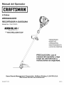
Operator's
Manual
®
4-Cycle
WEEDWACKER _ GAS TRIMMER
Model No. 316.791910
l
INCREDI.PULL_'
_
UNBELIEVABLE
with
STARTING
MAX FIREdlB
EA S E
N ITIO N °
•
•
•
•
•
•
SAFETY
ASSEMBLY
OPERATION
MAINTENANCE
PARTS LIST
ESPANOL, P. 15
CAUTION:
Before using
this product, read this
manual and follow all
safety rules and operating
instructions.
Sears Brands Management
Corporation,
Visit our website:
769-05777 P01
Hoffman
Estates, IL 60179 U.S.A.
www.craftsman.com
02/10
TABLE OF CONTENTS
Rules for Safe Operation
.......................................
Warranty Information
..........................................
Know Your Unit ..............................................
2
4
4
Assembly Instructions
.........................................
Oil and Fuel Information ........................................
4
5
Starting and Stopping Instructions ................................
Operating Instructions
.........................................
Maintenance and Repair Instructions ..............................
Cleaning and Storage .........................................
Troubleshooting Chart ........................................
Specifications
...............................................
Parts List ...................................................
Service Information
...................................
6
7
8
12
13
14
29
Back Cover
The purpose of safety symbols is to attract your attention to possible
dangers. The safety symbols, and their explanations, deserve your careful
attention and understanding.
The safety warnings do not by themselves
eliminate any danger. The instructions
or warnings they give are not
substitutes for proper accident prevention measures.
SYMBOL
MEANING
Attention is ALERT:
required inIndicates
order to avoid
personal
injury. May
SAFETY
danger,serious
warning
or caution.
be used in conjunction with other symbols or pictographs.
NOTE:
Advises of information or instructions
maintenance of the equipment.
vital to the operation or
injury to yourself or to others. Always follow the safety precautions
SPARK ARRESTOR
I_
NOTE
NOTE: For users on U.S. Forest Land and in the states of California, Maine,
Oregon and Washington.
All U.S. Forest Land and the state of California
(Public Resources Codes 4442 and 4443), Oregon and Washington require, by
law that certain internal combustion engines operated on forest brush and/or
grass-covered areas be equipped with a spark arrestor, maintained in effective
working order, or the engine be constructed, equipped and maintained for the
prevention of fire. Check with your state or local authorities for regulations
pertaining to these requirements. Failure to follow these requirements could
subject you to liability or a fine. This unit is factory equipped with a spark
arrestor. If it requires replacement, ask your LOCAL SERVICE DEALER to install
the Accessory Part #753-05297 Spark Arrestor Kit.
CALIFORNIA
PROPOSITION
65 WARNING
READ ALL INSTRUCTIONS
BEFORE OPERATING
Read the Operator's Manual and follow all warnings and safety
instructions.
Failure to do so can result in serious injury to the operator
and/or bystanders.
FOR QUESTIONS, CALL 1-800-4-MY-HOME®
SAFETY WARNINGS
When using the unit, you must follow the safety
rules. Please read these instructions before operating the unit in
order to ensure the safety of the operator and any bystanders.
Please keep these instructions for later use.
carefully. Be familiar with the controls and proper
• Do not operate this unit when tired, ill, or under the influence of alcohol,
drugs, or medication.
• Children and teens under the age of 15 must not use the unit, except for
teens guided by an adult.
• All guards and safety attachments must be installed properly before
operating the unit.
• Inspect the unit before use. Replace damaged parts. Check for fuel leaks.
Make sure all fasteners are in place and secure. Replace parts that are
cracked, chipped, or damaged in any way. Do not operate the unit with
loose or damaged parts.
• Carefully inspect the area before starting the unit. Remove all debris and
hard or sharp objects such as glass, wire, etc.
• Be aware of the risk of injury to the head, hands and feet.
• Clear the area of children, bystanders, and pets. At a minimum, keep all
children, bystanders, and pets outside a 50 feet (15 m) radius; there still
may be a risk to bystanders from thrown objects. Bystanders should be
encouraged to wear eye protection. If you are approached, stop the unit
immediately.
• Use only Craftsman XTRA QUIET TM 0.095 inch (2.413 mm) diameter original
equipment manufacturer replacement line. Never use metal-reinforced line,
wire or rope. These can break off and become dangerous projectiles.
• Squeeze the throttle control and check that it returns automatically
idle position. Make all adjustments or repairs before using unit.
property
or personal
to yourself
or to result
others.in
CAUTION:damage
Failure
to obey ainjury
safety
warning may
Always follow the safety precautions to reduce the risk of fire,
electric shock and personal injury.
SAFETY INSTRUCTIONS
WARNING:
• Read the instructions
use of the unit.
to
yourself and Failure
others. to
Always
safety can
precautions
WARNING:
obey afollow
safetythe
warning
result in to
injury
reduce the risk of fire, electric shock and personal injury.
All information, illustrations, and specifications in this manual are based on
the latest product information available at the time of printing. We reserve
the right to make changes at any time without notice.
THE ENGINE EXHAUST FROM THIS PRODUCT CONTAINS CHEMICALS
KNOWN TO THE STATE OF CALIFORNIA TO CAUSE CANCER, BIRTH
DEFECTS OR OTHER REPRODUCTIVE HARM.
• IMPORTANT
I to
DANGER:
to obeya
resultin
reduce the Failure
risk of fire,
electricsafetywamingwill
shock and personal
injury.serious I
to the
•
FOR GAS UNITS
IAIw'°""O sonesh
l
explode if ignited. Take the following precautions:
• Store fuel only in containers specifically designed and approved for the
storage of such materials.
• Always stop the engine and allow it to cool before filling the fuel tank.
Never remove the fuel tank cap or add fuel when the engine is hot. Always
loosen the fuel tank cap slowly to relieve any pressure in the tank before
fueling. Do not smoke.
• Always add fuel in a clean, well-ventilated outdoor area where there are
no sparks or flames. Do not smoke.
• Never operate the unit without the fuel cap securely in place.
• Avoid creating a source of ignition for spilled fuel. Wipe up any spilled fuel
from the unit immediately before starting the engine. Move the unit at
least 30 feet (9.1 m) from the fueling source and site before starting the
engine. Do not smoke.
• Never start or run the unit inside a closed room or building. Breathing exhaust
fumes can kill. Only operate this unit in a well-ventilated outdoor area.
WHILE OPERATING
• Wear safety glasses or goggles that meet ANSI Z87.1-1989 standards
and are marked as such. Wear ear/hearing protection when operating this
unit. Wear a face or dust mask if the operation is dusty.
• Wear heavy long pants, boots, gloves and a long sleeve shirt. Do not wear
loose clothing, jewelry, short pants, sandals or go barefoot. Secure hair
above shoulder level.
• The cutting attachment shield must always be in place while operating the
unit as a trimmer. Do not operate unit without both trimming lines
extended, and the proper line installed. Do not extend the trimming line
beyond the length of the shield.
• This unit has a clutch. The cutting attachment remains stationary when
the engine is idling. If it does not, have the unit adjusted by an authorized
service technician.
• Adjust the handle to your size in order to provide the best grip.
• Be sure the cutting attachment
starting the unit.
is not in contact with anything before
• Use the unit only in daylight or good artificial light.
• Avoid accidental starting. Be in the starting position whenever pulling the
starter rope. The operator and unit must be in a stable position while
starting. Refer to Starting/Stopping
Instructions.
• Use the right tool. Only use this tool for its intended purpose.
• Do not overreach. Always keep proper footing and balance.
• Always hold the unit with both hands when operating.
both handles or grips.
Keep a firm grip on
• Keep hands, face, and feet at a distance from all moving parts. Do not
touch or try to stop the cutting attachment when it rotates.
• Do not operate the engine faster than the speed needed to cut, trim or
edge. Do not run the engine at high speed when not cutting.
• Always stop the engine when cutting is delayed or when walking from one
cutting location to another.
• If you strike or become entangled with a foreign object, stop the engine
immediately and check for damage. Do not operate before repairing
damage. Do not operate the unit with loose or damaged parts.
AND
• Never store the unit with fuel in the tank, inside a building where fumes
may reach an open flame (pilot lights, etc.) or sparks (switches, electrical
motors, etc.).
Be sure to secure
• Store the unit in a dry area, locked up or up high to prevent unauthorized
use or damage, out of the reach of children.
• Never douse or squirt the unit with water or any other liquid. Keep handles
dry, clean and free from debris. Clean after each use, see Cleaning and
Storage instructions.
• Keep these instructions. Refer to them often and use them to instruct other
users. If you loan someone this unit, also loan them these instructions.
SAVE THESE INSTRUCTIONS
INTERNATIONAL
This operator's manual describes safety and international symbols and pictographs
complete safety, assembly, operating and maintenance and repair information.
MEANING
OTHER SAFETY WARNINGS
the spark plug for
• SAFETY
SYMBOL
• To reduce fire hazard, replace a faulty muffler and spark arrestor. Keep
the engine and muffler free from grass, leaves, excessive grease or
carbon build up.
• Allow the engine to cool before storing or transporting.
the unit while transporting.
• Do not touch the engine, gear housing or muffler. These parts get
extremely hot from operation, even after the unit is turned off.
• Stop the unit, switch the engine to off, and disconnect
maintenance or repair.
• Use only replacement parts or accessories recommended for this tool that
are distributed by Sears or a Craftsman outlet. Use of any replacement
parts or accessories purchased elsewhere may be hazardous, and will
also void your warranty.
• Keep unit clean of vegetation and other materials. They may become
lodged between the cutting attachment and shield.
SYMBOLS
•
that may appear on this product. Read the operator's
SYMBOL
MEANING
manual for
C RAFTSMAN
FU LL WAR RANTY
If this Craftsman product fails due to a defect in material or workmanship within two years from the date of purchase, return it to any Sears store, Parts &
Repair Service Center, or other Craftsman outlet in the United States for free repair (or replacement if repair proves impossible).
This warranty applies for only 90 days from the purchase date if this product is ever used for commercial
or rental purposes.
This warranty covers ONLY defects in material and workmanship. Sears will NOT pay for:
•
Expendable items that can wear out from normal use within the warranty period, such as cutting line, filters or spark plugs.
•
Repairs necessary because of accident or failure to operate or maintain the product according
to all supplied instructions.
•
Preventive maintenance, or repairs necessary due to improper fuel mixture, contaminated or stale fuel.
This warranty gives you specific legal rights, and you may also have other rights which vary from state to state.
Sears, Roebuck and Co., Hoffman Estates, IL 60179
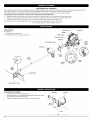
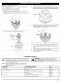
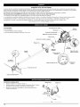
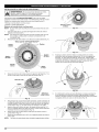
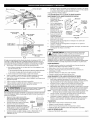
APPLICATIONS
Spark Arrestor
Spark Plug
As a trimmer:
• Cutting grass and light weeds
• Decorative trimming
Muffler Guard
around trees, fences, etc.
Starter Rope
Shaft Grip
Oil Fill
Plug/
Dipstick
On/Off Stop Control
Choke
Lever
Fuel
Cap
t
Throttle
Control
Shaft
Housing
\
Primer
Bulb
Air Filter
Cover
Line
Cutting
Blade
Cutting
Rapid
ADJUSTING
Rewind
TM
Shield
Head
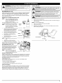
THE D-HANDLE
1.
Loosen the screws on the D-handle (Fig. 1).
2.
While holding the unit in the operating position (Fig.9), position the D-handle
to the location that provides the best grip.
3.
Tighten the clamp screws evenly, until the D-handle is secure.
Shaft Grip
Min.
(15.24
D-Handle
6 in.
cm)
'_
Screw
Fig. 1
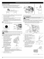
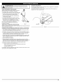
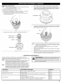
FUELING THE UNIT
WARNING:
OVERFILLING THE OIL CRANKCASE MAY CAUSE
SERIOUS PERSONAL INJURY. Check and maintain the proper oil
level in the crank case; it is important and cannot be
overemphasized. Check the oil before each use and change it as
needed. See Changing the Oil.
RECOMMENDED
any spilled fuel
Avoid
a source
ignition
for I
i _1 II upWARNING:
Addimmediately.
fuel in a clean,
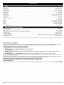
wellcreating
ventilated
outdoorof area.
Wipe
I
spilt fuel. Do not start the engine until fuel vapors dissipate.
I ^ I WARNING: Gasoline is extremely flammable, ignited vapors
OIL TYPE
i may explode. Always stop the engine and allow it to cool before
i filling the fuel tank. Do not smoke while filling the tank. Keep
i sparks and open flames at a distance from the area.
Using the proper type and weight of oil in the crankcase is extremely important.
Check the oil before each use and change the oil regularly. Failure to use the
correct oil, or using dirty oil, can cause premature engine wear and failure.
Use a high-quality SAE 30 weight oil of API (American Petroleum
service class SF, SG, SH.
ADDING
OIL TO CRANKCASE:
Institute)
I
WARNING:
i A
INITIAL USE
Remove
slowlythetofuel
avoid
from in
fuel
i spray. Never operate
thefuel
unitcap
without
capinjury
securely
place. I
i
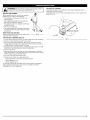
NOTE:
This unit is shipped without oil. In
order to avoid damage to the unit,
put oil in the crankcase before you
attempt to start the unit.
1.
2.
Your unit is supplied with one 3.04 fluid oz. (90
ml.) bottle of SAE 30 SF, SG, SH oil (Fig. 3).
Funnel
NOTE:
Save the empty oil bottle. It can
Spout
be used to measure the correct
amount during future oil changes.
See Changing the Oil.
Fig. 2
1.
Unscrew the top of the bottle of oil and
remove the paper seal covering the
opening. Replace the top. Next, cut
Oil Fill Plug __
the tip off the funnel spout (Fig. 2).
2.
Tip unit so that the back of the engine
is facing up in a vertical position.
O-Ring ___,,,/_/_
___
3.
Remove the oil fill plug from the
crankcase (Fig. 3).
4.
Pour the entire bottle of oil into the
Oil Fill Hole __
oil fill hole (Fig. 4).
Fig,3
NOTE:
Never add oil to the fuel or fuel
tank.
NOTE:
J
Do not overfill the tank.
3.
Wipe up any gasoline that may have spilled.
4.
Reinstall the fuel cap.
5.
Move the unit at least 30 ft. (9.1 m) from the fueling source and site
before starting the engine.
Gas Can Spout
Fuel Cap
FuelTank
Fig. 5
5.
Wipe up any oil that may have
\\
spilled and reinstall the oil fill plug.
___
Check oil before each use and change as
._
needed. Refer to Checking the Oil Level.
RECOMMENDED
FUEL TYPE
Old fuel is the primary reason for improper \
unit performance. Be sure to use fresh,
clean, unleaded gasoline. Dispose of the
old gasoline in accordance to federal,
'_
state and local regulations.
This is a four cycle engine. In
order to avoid damage to the
unit, do not mix oil with gasoline.
Definition of Blended Fuels
i
Remove the fuel cap (Fig. 5).
Place the gas container's spout into the fill hole on the fuel tank (Fig. 5)
and fill the tank.
NOTE:
Fig. 4
Today's fuels are often a blend of gasoline and oxygenates such as ethanol,
methanol or MTBE (ether). Alcohol-blended
fuel absorbs water. As little as
1% water in the fuel can form acids when stored. Use fresh fuel (less than
60 days old), when using alcohol-blended
fuel.
Using Blended Fuels
If you choose to use a blended fuel, or its use is unavoidable,
recommended precautions:
follow
• Always use fresh unleaded gasoline
• Use a gas stabilizer fuel additive
• Drain tank and run the engine dry before storing unit
Using Fuel Additives
The use of a gas stabilizer will inhibit corrosion and minimize the formation
of gum deposits. Using a fuel additive can keep fuel from forming harmful
deposits in the carburetor for up to six (6) months. Add 0.8 oz. (23 ml.) of
fuel additive per gallon of fuel according to the instructions on the fuel
additive container. NEVER add fuel additives directly to the unit's gas tank.
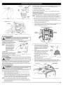
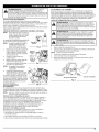
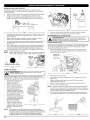
WARNING:
Operate this unit only in a well-ventilated outdoor area.
Primer Bulb
Carbon monoxide exhaust fumes can be lethal in a confined area.
Choke
Lever
WARNING:
Avoid accidental starting. Make sure you are in the
starting position when pulling the starter rope (Fig. 7). To avoid
serious injury, the operator and unit must be in a stable position
while starting.
STARTING
1.
2.
NOTE:
3.
4.
5.
INSTRUCTIONS
Check the oil level in the crankcase. Refer to Checking the Oil Level.
Fill the fuel tank with fresh, clean unleaded gasoline. Refer to Fuefing
the Unit.
There is no need to turn the unit on. The On/Off Stop Control is in
the ON (I) position at all times (Fig. 8).
\
Fully press and release the primer bulb 10 times, slowly. Some amount
of fuel should be visible in the primer bulb (Fig. 6). If fuel cannot be
seen in the bulb, press and release the bulb until fuel is visible.
Move the choke lever to Position 1 (Fig. 6).
Fig.
6
Crouch in the starting position (Fig. 7). SQUEEZE and HOLD the
throttle control for ALL further steps. Pull the starter rope in a
controlled motion 5 times.
NOTE:
6.
7.
The unit uses the Incredi-Pull TM starting system with MAX FIRE
IGNITION TM, which significantly reduces the effort required to start
the engine. You must pull the starter rope out far enough to hear
the engine attempt to start. There is no need to pull the rope
briskly-- there is no harsh resistance when pulling. Be aware that
this starting method is vastly different from (and much easier than)
what you may be used to.
Continue to squeeze the throttle control. Move the choke lever to
Position 2 (Fig. 6).
Continue to squeeze the throttle control. Pull the starter rope in a
controlled motion 3-5 times to start the engine.
8.
Continue to squeeze the throttle
up for 30-60 seconds.
control.
Allow the engine to warm
9.
Continue to squeeze
Position 3 (Fig. 6).
control.
Move the choke lever to
the throttle
Starter
Ro
10.
Continue to squeeze the throttle control. Run the unit for an
additional 60 seconds to complete the warm-up. The unit may be used
during this step.
IF...
The engine does not start, go back to step 3.
IF...
The engine fails to start after a few attempts, move the choke lever
to Position 3 and squeeze the throttle control. Pull the starter rope in
a controlled motion 3-8 times. The engine should start. If not, repeat.
IF WARM... If the engine is already warm, start the unit with the choker lever in
Position 2. After the unit starts, move the choker lever to Position 3.
STOPPING
INSTRUCTIONS
1.
Release your hand from the throttle control. Allow the engine to cool
down by idling.
2.
Press and hold the On/Off Stop Control in the OFF (O) position until
engine comes to a complete stop (Fig. 8).
Throttle
Control
Fig. 7
Start/On
Throttle Control
Fig. 8
(I)
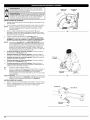
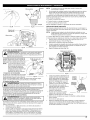
WARNING:
I _hb
Always wear eye, hearing, foot and body protection
I to reduce the risk of injury when operating this unit.
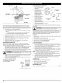
HOLDING
I
THE TRIMMER
Before operating the unit, stand in the operating
position (Fig. 9). Check for the following:
• The operator is wearing eye protection and
proper clothing
Decorative trimming is accomplished by removing all vegetation around
DECORATIVE TRIMMING
trees, posts, fences and more.
Rotate the whole unit so that the cutting attachment is at a 30 ° angle to the
ground (Fig. 10).
• With a slightly-bent right arm, the operator's
right hand is holding the shaft grip
• The operator's left arm is straight, the left hand
holding the handle
• The unit is at waist level
• The cutting attachment is parallel to the ground
and easily contacts the grass without the need
to bend over
BUMP KNOB LINE ADVANCE
Tap the bump knob on the ground to advance the
cutting line when necessary.
TIPS FOR BEST TRIMMING
--
Fig. 9
RESULTS
•
For best trimming
results, operate unit with throttle control fully squeezed.
•
•
Keep the cutting attachment parallel to the ground.
Do not force the cutting attachment. Allow the tip of the line to do the
cutting, especially along wails. Cutting with more than the tip will reduce
cutting efficiency and may overload the engine.
• Cut grass over 8 inches (200 ram) by working from top to bottom in small
increments to avoid premature line wear or engine drag.
• Cut from right to left.
• Slowly move the trimmer into and out of the cutting area at the desired
height. Move either in a forward-backward
or side-to-side motion. Cutting
shorter lengths produces the best results.
• Trim only when grass and weeds are dry.
• The life of your cutting line is dependent
upon:
- Proper adherence of explained trimming
techniques
- What vegetation is cut
- Where vegetation is cut
For example, the line will wear faster when trimming against a foundation
wall as opposed to trimming around a tree. It is normal for some line
breakage to occur from regular use.
Fig. 10
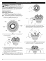
LINE INSTALLATION
FOR THE RAPID REWIND TMCUTTING HEAD
I
rope. These can break off and become dangerous projectiles.
I WARNING:
Never use metal-reinforced line, wire, chain or
I_
Always use Craftsman XTRA QUIET TM0.095 inch (2.413 mm) original
equipment manufacturer replacement line. Lines other than the specified
may make the engine overheat or fail.
There are two methods to replace the Rapid Rewind zu trimming
• Wind the inner reel with new line
• Install a pre-wound
line:
J
inner reel
Line Locking Hole
Winding
NOTE:
1.
the Inner Reel With New Line
It Is unnecessary to remove the bump knob to install a new
trimming line.
Cut two 7 ft (2.1 m) pieces of 0.095-inch (2.413 mm) trimming line.
Fig. 13
NOTE:
2.
Always use the correct line length when installing trimming line on
the unit. The line may not release properly if the line is too long.
Hold the outer spool and turn the inner reel counterclockwise
to line up
the arrows on the outer spool and inner reel (Fig. 11).
Top
View
Of The
Rapid
Rewind
TM
Arrows
Outer
Spool
Fig. 14
g
8.
Hole
Locking
Hole
Hold the outer spool. Wind the inner reel counterclockwise
until
approximately four (4) inches (102 mm) of line remain (Fig. 15). Avoid
contact of bump knob while winding. Ensure bump knob is tight on
shaft before proceeding, turn bump knob clockwise to tighten.
Inner
Reel
Bump
Knob
Fig. 11
3.
Detach old line ends from locking holes (Fig. 11) and pull old line out
through reel eyelets (Fig. 12).
Trimming
Line
Eyelet
Fig. 15
Line Loading Hole
9.
If winding the line becomes difficult or if the line jams, pull the ends of
the line from the spool (Fig. 16). Continue winding the inner reel
counterclockwise
until 4 inches of line remains on each side.
Fig. 12
4.
Making sure arrows are aligned, insert the end of a piece of trimming
line straight into one of the two eyelets in the outer spool. Push it up
through the line loading hole in the inner reel (Fig. 12). Do not bend the
line when inserting it into the eyelet.
5.
Insert the line into the locking hole (Fig. 13). Do not push the line more
than a 1/2 inch (12.7 mm) into the line locking hole. The line will form a
small loop (Fig. 13) when it is inserted correctly.
Pull the line from the outer spool until the line is tight against the inner
reel (Fig. 14).
6.
7.
Repeat procedures 4-6 with the second piece of line in the other eyelet.
NOTE:
Do not wind the inner reel before installing the second piece of line.
Fig. 16
CLEANING
THE RAPID REWIND
HEAD
TM
NOTE:
Also perform these steps when replacing inner reel with a new
prewound reel.
Cleaning the Rapid Rewind TM may be necessary if:
3.
Pull the inner reel with existing line from the outer spool.
4.
If rewinding with new line, remove any existing line from the inner reel
before cleaning. Remove any debris or grass from the knob, spring, inner
reel and foam seal. Wash the inner reel with warm soapy water (Fig. 19).
• A jammed or excessive line must be removed
• The Rapid Rewind TM becomes difficult to wind or does not operate
correctly when bumping the head on the ground.
1.
Hold the outer spool, and unscrew the bump knob counterclockwise
(Fig. 17).
Inner
Fig. 19
5.
Clean the shaft and the inner surface of the outer spool. To clean the
shaft underneath the plunger, press down on the plunger (Fig. 20).
Remove any dirt or debris from the shaft.
Fig. 17
Shaft
2.
Pull out the bump
knob,
spring
and foam
seal (Fig.
18).
Bump Knob _
Foam Seal _
Plunger _._
•
o
Fig. 20
-
NOTE:
7.
The inner reel must be totally dry before reinstalling it into the outer
spool. Do not lubricate the inner reel or outer spool assembly.
Place the cleaned and empty or new prewound inner reel into the outer
spool.
Place the bump knob, spring and foam seal onto the inner reel (Fig. 18).
8.
Press the bump knob down and tighten clockwise.
9.
Install new line in the empty inner reel as described
for the Rapid Rewind TM.
6.
Inner Reel__
Fig. 18
• MAINTENANCE
SCHEDULE
Perform these required maintenance procedures at the frequency stated in
the table. These procedures should also be a part of any seasonal tune-up.
NOTE:
Some maintenance procedures may require special tools or skills.
If you are unsure about these procedures take your unit to a Sears
or other authorized service dealer.
NOTE:
Maintenance, replacement, or repair of the emission control
devices and system may be performed by a Sears or other
authorized service dealer.
in Line Installation
•
WARNING:
To prevent serious injury, never perform
maintenance or repairs with unit running. Always service and
repair a cool unit. Disconnect the spark plug wire to ensure that
the unit cannot start.
FREQUENCY
MAINTENANCE
Every 10 hours
Clean and oil air filter
Page 10
After the 1st 10 hours
Change oil
Check rocker arm to valve clearance and adjust
Page 10
Page 11
Change oil
Page 10
Clean spark arrestor
Check rocker arm to valve clearance and adjust
Page 12
Page 11
Check spark plug condition and gap
Page 12
Every 40 hours
REQUIRED
SEE
9
CHECKING
THEOILLEVEL
Theimportance
ofchecking
andmaintaining
theproper
oillevelinthe
crankcase
cannot
beoveremphasized.
Check
oilbefore
each
use:
1. Stoptheengine
andallow
oiltodrain
intothecrankcase.
2. Place
theengine
onanelevated,
level
surface
withthecutting
head
shield
hanging
offthesurface
togetanaccurate
oillevel
reading
(Fig.
21).
Fill Level
Fig. 21
Fig. 25
3.
Keep dirt, grass clippings and other debris out of the engine. Clean the
area around the dipstick before removing it.
4.
Remove the oil fill plug.
Look into the oil fill hole, use a flashlight if needed. The oil should be
just touching the innermost thread (Fig. 22).
If the oil level is not touching the innermost thread on the oil fill hole,
add a small amount of oil to the oil fill hole and recheck (Fig. 22).
Repeat this procedure until the oil level reaches the innermost thread
on the oil fill hole.
5.
6.
NOTE:
Do not overfill the unit.
NOTE:
Make sure the O-ring is in place on the oil fill plug when checking
and changing the oil (Fig. 23).
OilFillPlug
__
AIR FILTER MAINTENANCE
unit off and allow
to cool
beforepersonal
you clean
or service
I WARNING:
To itavoid
serious
injury,
always it.turn the
I _lb
Cleaning
the Air Filter
Clean and re-oil the air filter every 10 hours of operation. It is an important
item to maintain. Failure to maintain your air filter properly can result in poor
performance or can cause permanent damage to your engine.
1.
_
Open the air filter cover. Push the tab on the under side of the cover
inward. Then pull the air filter cover out and up. (Fig. 26).
Air
Filter
Cover.__
Air Filter
_
Max Oil Fill Line /
Fig. 23
Fig. 22
CHANGING
I _
THE OIL
I WARNING:
Change the oil after the first 10 hours and every 40 hours of operation
thereafter. Change the oil while the engine is still warm. The oil will flow
freely and carry away more impurities.
1.
Unplug spark plug boot to
prevent accidental starting.
2.
3.
Remove the oil fill plug.
Pour the oil out of the oil fill hole
and into a container by tipping
the unit to a vertical position
(Fig. 24). Allow ample time for
complete drainage.
Wipe up any oil residue on the
unit and clean up any oil that
may have spilled. Dispose of
the oil according to federal,
state and local regulations.
Refill the crankcase with 3.04
fluid ounce (90 ml) of SAE 30
SF, SG, SH oil.
4.
5.
Tab
Wear gloves to prevent injury when handling unit.
NOTE:
6.
Use the bottle and spout
saved from initial use to
Fig. 24
measure the correct
amount of oil. The top of the label on the bottle measures
approximately 3.04 ounces (90 ml) (Fig. 25). Check the level; See
Checking the 0il Level. If the level is low, add a small amount of oil
and recheck. Do not overfill (Fig. 25).
Replace the oil fill plug.
7.
Reconnect the spark plug boot.
Fig. 26
2.
3.
Remove the air filter (Fig. 26).
Wash the filter in detergent and water
(Fig. 27). Rinse the filter thoroughly and
allow it to dry.
4.
Apply enough clean SAE 30 motor oil to
lightly coat the filter (Fig. 28).
5.
Squeeze the filter to spread and remove
excess oil (Fig. 29).
6.
Replace the filter (Fig. 26).
NOTE:
7.
8.
If the unit is operated without the air
filter, you will VOID the warranty.
Reinstall the air filter cover. Position the
slots on the top of the air filter cover
onto the tabs at the top of the back
plate (Fig. 30).
Swing
tab on
snaps
the air
i
Fig. 27
the cover down until the
the air filter backplate
into place in the slot on
filter cover (Fig. 31).
Fig. 28
10
I
Tabs
Back Plate
Checking the fuel, cleaning the air filter, and adjusting the idle speed should
solve most engine problems. If not and all of the following are true:
• the engine will not idle
• the engine hesitates or stalls on acceleration
• there is a loss of engine power
Have the carburetor
serviced by a Sears or other qualified service dealer.
ROCKER ARM CLEARANCE
_
Fig, 29
Locking
Tab
Fig, 30
This requires disassembly of the engine. If you feel unsure or unqualified to
perform this, take the unit to a Sears or other qualified service dealer
NOTE:
Inspect the valve to rocker arm clearance with a feeler gauge after
the first 10 hours of operation and every 40 hours of operation.
• The engine must be cold when checking or adjusting the valve clearance.
• This task should be performed inside, in a clean, dust free area.
1.
Remove the six (6) screws on the back of the engine cover with a Flathead or T-25 Torx screwdriver (Fig. 33).
2.
Disconnect
3.
Clean dirt from around the spark plug. Remove the spark plug from the
cylinder head by turning a 5/8 in. socket counterclockwise.
4.
Remove the engine cover (Fig. 33).
the spark plug wire.
View
Of The
Rear
Engine
Cover
Remove
Screws
Remove
Screws
Tab
Fig. 31
IDLE SPEED ADJUSTMENT
i lW O..o
thecuttn0he
n0 I
adjustments. Wear protective clothing and observe all safety
instructions to prevent serious personal injury.
The idle speed of the engine is
adjustable. An idle adjustment screw
is between the air filter cover and the
engine starter housing (Fig. 32).
Idle Adj
Fig. 33
Clean dirt from around the rocker arm
cover. Remove the screw holding the
rocker arm cover with a large flat blade
screwdriver or Torx T-25 bit (Fig. 34).
Remove the rocker arm cover and
NOTE:
Careless adjustments can
seriously damage your
unit. Aside from the idle
speed, only a Sears or
other qualified service
dealer should make
carburetor adjustments.
1. Check Fuel
6.
Old fuel is usually the reason for idle
speed problems. Drain and refill the
tank with fresh fuel prior to making
any adjustments. Refer to Oil and Fuel Information.
2. Clean Air Filter
Fig. 32
gasket.
Pull the starter rope slowly to bring the
piston to the top of its travel, (known
as top dead center). Check that:
The piston is at the top of its travel.
Look in the spark plug hole to view the
piston (Fig. 35)
has stopped
rotating
before
The condition of the air filter is important to the operation of the unit. A dirty
air filter will restrict air flow. This is often mistaken for an out of adjustment
idle. Check the condition of the air filter before adjusting the idle speed screw.
Refer to Air Filter Maintenance.
3. Adjust
If these statements
you turn it off and
7.
.\
Spar
Plug Hole
Both rocker arms move freely, and
both valves are closed.
iAiw o..o
to eventse
ousnuesuethe
eson
I
cutting attachment
set it down.
Rocker Arm
Cover
Fig. 34
are not true, repeat step 6.
Slide the feeler gauge between the rocker arm and the top of each
valve stem. Measure the clearance between the valve stem and rocker
arm (Fig. 35 & 36). Measure both the intake and exhaust valves.
Rocker Arms
INTAKE
Adjusting
Idle Speed Screw
adjustments. Wear protective clothing and observe all safety
I WARNING:
The cutting
attachment
spin during idle speed I
instructions to prevent
serious
personal may
injury.
I_
Nuts
EXHAUST
If, after checking the fuel and cleaning the air filter, the engine still will not
idle, adjust the idle speed screw as follows:
1.
Start the engine and let it run at a high idle for a minute to warm up.
Refer to Starting/Stopping
Instructions.
2.
Release the throttle trigger and let the engine idle. If the engine stops,
insert a small Phillips screwdriver in between the Air Filter Cover and
the Engine Cover (Fig. 32). Turn the idle speed screw in, clockwise, 1/8
of a turn at a time (as needed) until the engine idles smoothly.
NOTE:
3.
The cutting head should not rotate when the engine idles.
Feeler
Gauge
@
Fig, 35
If the cutting attachment rotates when the engine idles, turn the idle
speed screw counterclockwise
1/8 of a turn at a time (as needed), until
the head stops turning.
11
SPARK ARRESTOR
Adjusting Nut
Remove the rear engine
cover. See Rocker Arm
Clearance.
2.
With a flat blade
screwdriver or Torx T-20
bit and a T-25 bit,
remove the screws
Rocker Arm
.003-.006 in.
(.076-.152 mm)
t
Feeler
3.
Gauge
4.
Valve
Stem
MAINTENANCE
1.
attaching the spark
arrestor diverter to the
muffler (Fig. 38).
Pull the spark arrestor
diverter out of the
muffler. Remove the
spark arrestor diverter.
Remove the spark
arrestor screen from the
spark arrestor diverter.
Muffler
Slot
Spark Arrestor
Screen
T-25 Screw
Spark Arrestor
Cover
T-30
Screw
Fig. 38
5.
Clean the spark arrestor
screen with a wire brush or replace it.
The recommended clearance for both intake and exhaust is .003 - .006 in.
(.076 - 0.152 mm). Use a standard automotive .005 in. (0.127 mm) feeler
gauge. The feeler gauge should slide between the rocker arm and valve stem
with a slight amount of resistance, without binding. See Figures 35 and 36.
6.
Reinstall the spark arrestor screen, spark arrestor diverter and screws.
8.
I 41_iL
Fig. 36
If the clearance is not within specification:
a.
b.
Turn the adjusting nut using a 5/16 inch (8 mm) wrench or nut driver
(Fig. 36).
•
To increase clearance, turn the adjusting nut counterclockwise.
•
To decrease clearance, turn the adjusting nut clockwise.
CLEANING
unit off and allow it to cool before you clean or service it.
I WARNING:
T° av°id serious personal injury, always turn Your
Use a small brush to clean off the outside of the unit. Do not use strong
detergents. Household cleaners that contain aromatic oils such as pine and
lemon, and solvents such as kerosene, can damage plastic housing or
handle. Wipe off any moisture with a soft cloth.
STORAGE
9.
Recheck both clearances, and adjust as necessary.
Reinstall the rocker arm cover using a new gasket. Torque the screw to
20-30 in•lb (2.2-3.4 N•m).
10.
11.
Check the spark plug and reinstall. See Replacing the Spark Plug.
Replace the spark plug wire.
• Allow the engine to cool before storing.
• Lock up the unit to prevent unauthorized
12.
Reinstall the engine cover. Check alignment of the cover before
tightening the screws. Tighten screws.
• Store the unit in a dry, well-ventilated area.
• Store the unit out of the reach of children.
REPLACING
THE SPARK PLUG
Never store the unit with fuel in the tank where fumes may reach an open
flame or spark.
Grasp the plug wire firmly and pull the cap from the spark plug.
Clean dirt from around the spark plug. Remove the spark plug from the
cylinder head by turning a 5/8 in. socket counterclockwise.
1.
Drain all gasoline from the gas tank into a container. Do not use gas
that has been stored for more than 60 days. Dispose of the old gasoline
in accordance to federal, state, and local regulations.
2.
Start the engine and allow it to run until it stalls. This ensures that all
gasoline has been drained from the carburetor.
3.
Allow the engine to cool. Remove the spark plug and put 1 oz. (30 ml)
of high quality motor oil into the cylinder. Pull the starter rope slowly to
distribute the oil. Reinstall the spark plug.
NOTE:
I _
in the engine could damage the cylinder.
I WARNING:
Do not sand blast, scrap e or clean electrodes.
Grit
4.
Replace cracked, fouled or dirty spark plug. Set the air gap at 0.025 in.
(0.635 mm.) using a feeler gauge (Fig. 37).
5.
Install a correctly-gapped
spark plug in the cylinder head. Turn the 5/8
in. socket clockwise until snug.
If using a torque wrench, torque to:
110-120 in,•lb, (12.3-13.5 N•m}
_J
j--\
L
Remove the spark plug and drain all of the oil from the cylinder
before attempting to start the trimmer after storage.
4.
Change the oil, referring to Changing the Off. Dispose of the old oil in
accordance to federal, state and local regulations.
5.
Thoroughly clean the unit and inspect for any loose or damaged parts.
Repair or replace damaged parts and tighten loose screws, nuts or
bolts. The unit is ready for storage.
TRANSPORTING
• Allow the engine to cool before transporting.
• Secure the unit while transporting.
Do not over tighten.
0.025 in.
(0.635 mm)
• Drain the gas tank before transporting.
• Tighten gas cap before transporting.
REPLACEMENT
Craftsman
Fig.37
12
use or damage.
LONG TERM STORAGE
Use a replacement part number 753-05784 or Champion spark plug,
#RDZ19H. The correct air gap is 0.025 in. (0.635 mm.). Remove the plug
after every 40 hours of operation and check its condition.
1.
Stop the engine and allow it to cool. Remove the six (6)screws on the back
of the engine cover with a Flat-head or T-25 Torx screwdriver (Fig. 33).
2.
3.
•
LINE
XTRA QUIET Spiral Line ........................................................
85621
I
PROBLEM
SOLUTION
Empty fuel tank
Fill fuel tank with fresh fuel
Engine is flooded
Pull the starter rope while holding the throttle control
Fouled spark plug
Replace the spark plug
I=1#[_1#1=kVAVl
Imlml#[Oil/IIm]m=l
Air filter is plugged
Improper carburetor
Replace or clean the air filter
adjustment
Take to a Craftsman or other qualified service dealer for adjustment
I=l#[e]l#l= kvAvl
IIIIII _[oil f_,[o[o] ;:1111
;:1
:f_,_l/ ;:1
Old fuel
Drain fuel tank and add fresh fuel
Dirty air filter
Clean or replace the air filter
I::1#[€]l#l: IIr:T_ _(,:]1:,fo]V,
vA::1
:[o] :1_11Ir_*1
II I(,.lkvAvl
-"I=1_[o,]ljl I / I_[€:1
Old fuel
Drain fuel tank and add fresh fuel
Fouled spark plug
Replace the spark plug
[o,].l]llil_[€]I-'l=r±Im]
_'r,_Vjl!
aH_[e]ldF_*1
m]Vl_*1
_[o]_ !l_l:l
Cutting head bound with grass
Stop the engine and clean cutting head
Inner reel bound up
Rewind the inner reel
Line welded
Disassemble,
Not enough line is exposed
Push the bump knob and pull out line until 4 inches (102 mm) of line is
outside of the cutting head
remove the welded section and rewind
[e,].l]lI il _ [€] IN I _I =IF±_
m]Vl±1_[e] :_'_ LIJ_ [e,[e]_ i | ;[e] | Ir_*1
:) li'd
Oil, cleaner or lubricant in cutting head
Clean and thoroughly
dry the cutting head
!.........................................................................................................................................................................................................................................................................................................................................................................................................................................................................................................................................
NEED MORE HELP
13
I=1_
[_l_l=ril
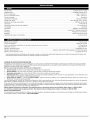
Engine Type ..................................................................................................
Displacement
..................................................................................................
Operating
Air-Cooled, 4-Cycle
1.77 cu. in. (29 cc)
RPM .................................................................................................
6,800 - 9,300 rpm
Idle Speed RPM .................................................................................................
Ignition Type ..........................................................................................................
3,600 - 4,400 rpm
Electronic
Ignition Switch .....................................................................................................
Rocker Switch
Valve clearance .........................................................................................
Spark Plug Gap .............................................................................................
Lubrication
..........................................................................................................
003-.006 in. (.076-.152 mm))
0.025 inch (0.635 mm)
SAE 30 Oil
Crankcase Oil Capacity .............................................................................................
Fuel .................................................................................................................
3.04 oz (90 ml)
Unleaded
Carburetor ................................................................................................
Starter .................................................................................................
Muffler
Diaphragm, All-Position
Incredi-Pull TM Auto Rewind
.......................................................................................................
Baffled with Guard
Throttle ....................................................................................................
Fuel Tank Capacity .................................................................................................
Drive Shaft Housing
Manual Spring Return
14 oz (414 ml)
...................................................................................................
Steel Tube
Throttle Control .................................................................................................
Finger-Tip Trigger
Approximate Unit Weight (No fuel, with handle, shield and cutting head) .......................................................
Cutting Mechanism: ...............................................................................................
Line Spool Diameter: ............................................................................................
Trimming Line Diameter: .....................................................
Craftsman
Cutting Path Diameter ..........................................................................................
* All specifications
are based on the latest product information
REPAIR PROTECTION
13.5 Ibs (6 kg)
Rapid Rewind TM
3 inches (76.2 mm)
XTRA QUIET 0.095 inch (2.413 mm) spiral cutting line
17 inches (43.18 cm)
available at the time of printing. We reserve the right to make changes at any time without notice.
AGREEMENTS
Congratulations on making a smart purchase. Your new Craftsman® product is designed and manufactured for years of dependable operation.
products, it may require repair from time to time. That's when having a Repair Protection Agreement can save you money and aggravation.
But like all
Here's what the Repair Protection
Agreement*
includes:
[]
Expert service by our 10,000 professional repair specialists
[]
[]
Unlimited service and no charge for parts and labor on all covered repairs
Product replacement
up to $1500 if your covered product can't be fixed
[]
Discount of 10% from regular price of service and related installed parts not covered by the agreement; also, 10% off regular price of preventive
maintenance checks
[]
Fast help by phone - we call it Rapid Resolution - phone support from a Sears representative. Think of us as a "talking owner's manual."
Once you purchase the Repair Protection Agreement, a simple phone call is all that it takes for you to schedule service. You can call anytime day or night, or
schedule a service appointment online.
The Repair Protection Agreement is a risk-free purchase. If you cancel for any reason during the product warranty period, we will provide a full refund. Or a
prorated refund anytime after the product warranty period expires. Purchase your Repair Protection Agreement today!
Some limitations
and exclusions apply. For prices and additional information,
call 1-800-827-6655.
*Coverage in Canada varies
Sears Installation
Service
on some items. For full details,
call Sears Canada
at 1-800-361-6665.
For Sears professional installation of home appliances, garage door openers, water heaters and other major home items in the U.S.A. or Canada, call 1-800-4-MY-HOME®.
14
Manual
del Operador
®
4 Ciclos
WEEDWACKER _
RECORTADOR A GASOLINA
Model No. 316.791910
INCREDI.PULL_'
_"
UNBELIEVABLE
con
MAX
STARTING
E A S E TM
FIRE_IBN
ITION
°
•
•
•
•
•
SEGURIDAD
MONTAJE
OPERACION
MANTENIMIENTO
LISTA DE PARTES
PRECAUCION:
Lea el
manual del operador y siga
todas las advertencias e
instrucciones de seguridad.
Sears Brands Management
Corporation,
Hoffman
Estates, IL 60179 U.S.A.
Visite nuestro sitio web: www.craftsman.com
769-05777 P01
02/10
INDICE DE CONTENIDOS
Normas para una operaci6n segura .............................
Garantia ...................................................
Conozca su unidad ..........................................
Instrucciones de ensamble ....................................
16
18
18
18
Informaci6n del aceite y del combustible
.........................
Instrucciones de arranque y apagado ............................
Instrucciones de operaci6n ....................................
Instrucciones de mantenimiento y reparaci6n ......................
Limpieza y almacenamiento
...................................
Cuadro de soluci6n de problemas
..............................
Especificaciones
............................................
Lista de Piezas .............................................
19
20
21
22
26
27
28
29
Llamadas a apoyo al cliente
.........................
Los simbolos de seguridad se utilizan para Ilamar su atencion sobre posibles
peligros. Los simbolos de seguridad y sus explicaciones merecen toda su
atencion y comprensi6n. Los simbolos de seguridad no eliminan ningQn peligro
pot si mismos. Las instrucciones o advertencias que ofrecen no substituyen
las medidas adecuadas de prevencion de accidentes.
SIMBOLO
precaucion. Debe
ALERTA
DE prestar
SEGURIDAD:
atenci6n para evitar
Indica sufrir
peligro,
graves
advertencia
lesiones
personales. Puede ser utilizado junto con otros s[mbolos o figuras.
NOTA:
Contraportada
LEA TODAS LAS INSTRUCCIONES
ANTES DE LA OPERACION
AI utilizar la unidad, debe observar las reglas
de seguridad. Lea estas instrucciones antes de operar la unidad a
fin de garantizar la seguridad del operador y cualquier transeQnte.
Guarde estas instrucciones para uso posterior.
• Lea las instrucciones cuidadosamente.
el uso adecuado de la unidad.
Familiaricese con los controles y
= No opere esta unidad cuando este cansado,
de alcohol, drogas o medicamentos.
enfermo o bajo la influencia
• Los nifios y los adolescentes menores de 15 afios de edad no deben usar la
unidad. Los adolescentes pueden hacerlo bajo la supervisi6n de un adulto.
• Todos los dispositivos de protecci6n y los accesorios de seguridad
deben estar instalados adecuadamente antes de operar la unidad.
= Inspeccione la unidad antes de usarla. Reemplace las piezas dafiadas.
Verifique si hay fugas de combustible. AsegQrese de que todos los
fijadores esten en su lugar y asegurados. Reemplace las piezas que
esten agrietadas, astilladas o da_adas en cualquier forma. No opere la
unidad con piezas sueltas o da_adas.
• Inspeccione cuidadosamente el _rea antes de operar la unidad. Elimine todos
los escombros y los objetos duros o filosos tales como cristal, alambre, etc.
del riesgo de lesi6n en la cabeza, las manos y los pies.
• No permita nifios, espectadores ni mascotas en el _rea. Los nifios, los
espectadores y las mascotas deben estar fuera de un radio de 50 pies
(15 m.) como minimo; de todas formas los espectadores correr&n el
riesgo de set golpeados por objetos lanzados pot la unidad. Se debe
exhortar a los espectadores a que usen protecci6n para los ojos. Si se le
acerca alguien apague la unidad de inmediato.
= Use s61o linea de reemplazo del Craftsman XTRA QUIET TM fabricante
original del equipo con un di&metro de 0.095 de pulgada (2.413 mm).
Nunca use linea reforzada con metal, alambre o soga. Se pueden romper
y convertirse en proyectiles peligrosos.
• Optima el control del estrangulador y compruebe que regresa
autom_ticamente a la posici6n de marcha en vacio. Haga todos los
ajustes o reparaciones antes de usar la unidad.
16
El no seguir una advertencia de seguridad
puede conducir a que usted u otras personas sufran lesiones. Siga
siempre las precauciones de seguridad para reducir el riesgo de
incendio, descarga el6ctrica y lesiones personales.
PRECAUCION:
El no seguir una advertencia de seguridad
puede conducir a dafio patrimonial o a que usted u otras
personas sufran lesiones personales. Siga siempre las
precauciones de seguridad para reducir el riesgo de incendio,
descarga electrica y lesiones personales.
Lea el manual del operador y siga todas las advertencias e
instrucciones de seguridad. De no hacerlo, el operador y/o los
espectadores pueden sufrir graves lesiones. SI TIENE PREGUNTAS,
LLAME AL 1-800-4-MY-HOME®
Toda la informaci6n, las ilustraciones y las especificaciones contenidas en
este manual se basan en la informaci6n m_s reciente disponible en el
momento de impresi6n del manual. Nos reservamos el derecho de hacer
cambios en cualquier momento sin aviso previo.
INFORMACION
ADVERTENCIA:
• Este consciente
ADVERTENCIA:
65 DE CALIFORNIA
• IMPORTANTE
El no obedecer una advertencia de seguridad puede
conducir a que usted u otras personas sufran graves lesiones. Siga
siempre las precauciones de seguridad para reducir el riesgo de
incendio, descarga electrica y lesiones personales.
NOTA: Para los usuarios en tierras forestales de los EE.UU. y en los estados de
California, Maine, Oregon y Washington. Todos los terrenos forestales de los EE.UU.
y el estado de California (C6digos de Recursos Publicos 4442 y 4443), Oregon y
Washington, requieren por decreto, que ciertos motores de combustion interna que se
hagan funcionar en zonas boscosas y/o zonas cubiertas por pastizales, esten
equipados con un parachispas, que sean mantenidos en buen estado de
funcionamiento o que el motor sea construido, este equipado y sea mantenido para
evitar incendios. Consulte los reglamentos pertinentes a esos requisitos con las
autoridades estatales o locales. El incumplimiento de esos requisitos puede
responsabilizarle o someterle a la imposici6n de una multa. Esta unidad fue equipada
en la fabrica con un parachispas, Si requiere sustituci6n, hay una Pantalla
Parachispas disponible, Pieza # 753-05297 al contactar el departamento de servicio.
LAS EMISIONES DEL MOTOR DE ESTE PRODUCTO CONTIENEN
SUBSTANCIAS QUIMICAS QUE EL ESTADO DE CALIFORNIA CONOCE
COMO CAUSANTES DECANCER, DEFECTOS DE NACIMIENTO U OTROS
DAI_IOS REPRODUCTIVOS.
o
Le ofrece informaci6n o instrucciones que son esenciales para la
operaci6n o mantenimiento del equipo.
PELIGRO:
PARACHISPAS
PROPOSICION
SIGNIFICADO
DE SEGURIDAD
AVISOS DE SEGURIDAD
GASOLINA
iA
•
PARA LAS UNIDADES
QUE FUNCIONAN
CON
pueden explotar si se encienden. Tome las siguientes precauciones:
• AImacene el combustible solamente en recipientes disefiados y aprobados
especificamente para el almacenamiento de dichos materiales.
• Pare siempre el motor y deje que se enfrie antes de Ilenar el tanque de
combustible. Nunca quite la tapa del tanque de combustible, ni agregue
combustible, cuando el motor este caliente. Siempre afioje la tapa del
tanque de combustible lentamente para aliviar cualquier presi6n que
haya en el tanque antes de cargar combustible. No fume.
• Siempre agregue el combustible en un _rea exterior bien ventilada,
donde no haya chispas ni llamas. No fume.
= Nunca opere la unidad sin la tapa de combustible
bien colocada en su lugar.
• Evite crear una fuente de ignici6n para el combustible derramado. Limpie
de la unidad inmediatamente cualquier combustible derramado antes de
arrancar el motor. Mueva siempre la unida a 30 pies (9.1 m) como minimo
de la fuente y sitio de combustible antes de arrancar el motor. No fume.
• Nunca arranque ni use la unidad dentro de una habitaci6n o edificio
cerrado. Respirar los vapores de escape puede causarle la muerte.
Opere esta unidad s61o en un _rea exterior bien ventilada.
DURANTE
LA OPERAClON
• Use lentes o gafas de protecci6n que cumplan con las normas ANSI
Z87.1-1989, y protecci6n para sus oidos/audici6n mientras opere esta
unidad. Use siempre una m&scara facial o para protegerse contra el
polvo si la operaci6n levanta polvo.
• Use pantalones largos y gruesos, botas, guantes y camisa de manga
larga. No use ropa holgada, alhajas, pantalones cortos, sandalias ni este
descalzo. Sostenga el cabello sobre el nivel de los hombros.
• La protecci6n accesoria de corte debe estar siempre colocada en su
lugar mientras opere la unidad. No opere la unidad con las dos lineas de
corte extendidas, y la linea correcta instalada. No extienda la linea de
corte m_s all_ de la Iongitud de la protecci6n.
I
• Esta unidad cuenta con un embrague. El accesorio de corte permanece
estacionario cuando el motor est& en marcha lenta. Si no Io hace, haga
ajustar la unidad por un tecnico de servicio autorizado.
• Ajuste la manija a su tamafio de modo que le brinde el mejor agarre.
• AsegOrese de que el accesorio de corte no est_ en contacto con ningOn
objeto antes de arrancar la unidad.
• Use la unidad Onicamente con la luz del alia o con buena luz artificial.
• Evite arrancar la unidad accidentalmente.
Col6quese en posici6n de inicio
siempre que tire de la cuerda de arranque. El operador y la unidad deben
estar en una posici6n estable al comenzar. Lea las Instrucciones de
Arranque y Apagado.
• Use la herramienta adecuada. No use esta unidad para ninguna tarea
para la cual no ha sido disefiada.
• No se estire demasiado. Mantenga siempre una posici6n y equilibrio adecuados.
• Sostenga siempre la unidad con ambas manos mientras este en
funcionamiento. Sostenga con firmeza tanto el mango como la manija auxiliar.
• Mantenga las manos, la cara y los pies lejos de todas las partes m6viles.
No intente tocar ni detener el accesorio de corte mientras gira.
• No toque el motor, el bastidor del engranaje ni el silenciador. Estas partes
se calientan mucho con la operaci6n. Luego de apagar la unidad,
permanecen calientes durante un tiempo breve.
• No opere el motor a una velocidad mayor que la necesaria para cortar,
recortar o recortar los bordes. No haga funcionar el motor a alta velocidad
mientras no est_ cortando.
• Apague siempre el motor cuando demore el corte o mientras camina
entre zonas de corte.
• Apague el motor para realizar todo el mantenimiento,
cambio del accesorio de corte u otros accesorios.
DE SEGURIDAD
• Mantenga la unidad libre de vegetaci6n y otros materiales.
alojarse entre el accesorio de corte y la protecci6n.
SIGNIFICADO
Pueden
• Para reducir el riesgo de incendio, cambie los silenciadores y amortiguadores de chispas defectuosos, mantenga el motor y el silenciador
libre de pasto, hojas, grasa excesiva o acumulaciones de carbono.
OTRAS ADVERTENOIAS
DE SEGURIDAD
• Nunca guarde la unidad con combustible en el tanque, dentro de un
edificio donde las emanaciones puedan alcanzar una llama viva (luces
pilotos, etc.) o chispas (interruptores, motores electricos, etc.).
• Espere que el motor se enfrie antes de guardar o transportar la unidad.
AsegOrese de que la unidad este segura al transportarla.
• Guarde la unidad bajo Ilave en un lugar adecuado y seco para evitar que sea
usada por personas no autorizadas y se dafie, fuera del alcance de los nifios.
• Nunca moje ni rocie la unidad con agua ni con ningOn otro liquido.
Mantenga las manijas secas, limpias y sin residuos. Limpie la unidad
luego de cada uso, lea las instrucciones de Limpieza yAImacenamiento.
• Guarde estas instrucciones. ConsOltelas con frecuencia y utilicelas para
ensefiar a otros usuarios. Si le presta esta unidad a alguien, prestele
tambien estas instrucciones.
CONSERVE
E INTERNACIONALES
ESTAS INSTRUCClONES
•
Este manual del operador describe los simbolos y figuras de seguridad e intemacionales que pueden aparecer en este producto.
para obtener informaci6n completa acerca de la seguridad, ensamble, operaci6n y mantenimiento y reparaci6n.
SJMBOLO
o
• Utilice solamente piezas o accesorios de reemplazo recomendados para
esta herramienta que sean distribuidos por Sears o por un
establecimiento comercial de Craftsman. El uso de cualquier pieza de
reemplazo o accesorio adquirido en cualquier otro lugar puede resultar
peligroso, y tambien anular_ su garantia.
• Si golpea o se enreda con algOn objeto extrafio, apague el motor de
inmediato y verifique si hay dafios. Repare todos los dafios antes de volver a
intentar operar la unidad. No opere la unidad si tiene piezas flojas o dafiadas.
• SIMBOLOS
reparaciones
SJMBOLO
Lea el manual del operador
SIGNIFICADO
17
GARANTIA
TOTAL
DE CRAFTSMAN
Si este producto de Craftsman Professional falla debido a un defecto en el material o en la mano de obra dentro de un periodo de dos a_os a partir de la
fecha de compra, devuelvalo a cualquier tienda o Centro de Servicio de Piezas y Reparaciones Sears u otro establecimiento de Craftsman en los Estados
Unidos para que sea reparado sin costo alguno (o ser reemplazado si resulta imposible repararlo).
Esta garantia se aplica solamente durante 90 dias si este producto en algQn momento se utiliza para fines comerciales
Esta garantia abarca SOLAMENTE los defectos en el material o en la mano de obra. Sears NO pagarb:
• Los articulos consumibles
que se desgasten
o de alquiler.
debido al uso normal dentro del periodo de garantia.
• Las reparaciones necesarias debidas a accidente asi como por no operar o no mantener el equipo de acuerdo con todas las instrucciones
• Mantenimiento preventivo, o las reparaciones necesarias debido a mezcla incorrecta de combustible, combustible contaminado o viejo.
Esta garantia le concede a usted derechos
provistas.
legales especificos, y usted pudiera tener otros derechos que varian de un estado a otro.
Sears, Roebuck and Co., Hoffman Estates, IL 60179
APLICAClONES
Amortiguardor de chispas
Como recortador:
Bujia de
encendido
Silenciador
• Corte de cesped y hierbas delgadas
• Recorte decorativo alrededor de _rboles, cercos, etc.
Protecci6n del silenciador
Mango de la cuerda de arranque
Manjo del eje
Control de encendido y apagado
Manija en D
X
Tapa del
combustible
Gatillo del
regulador
Bastidor
del eje
Tap6n del aceite /
Varilla de medici6n
Palanca azul del
obturador
Cuchilla de
corte de linea
Cubierta
Protecci6n
Cabeza
de Rapid
Rewind
del filtro
de corte
TM
AJUSTE DE LA MANIJA EN D
1.
Afioje los tornillos en la manija en D (Fig. 1).
2.
Mientras sostiene la unidad en posici6n de operaci6n (Fig. 9), coloque
la manija en Den la posici6n que le brinde el mejor agarre.
3.
Ajuste los tornillos de la abrazadera en forma pareja hasta que la
manija en D este firme.
Mango del eje
Minimo
6 pulg.
Manija en D
de
(15.24
__
cm)
Tornillo
Fig. 1
18
de aire
Bombilla del
cebador
ADVERTENClA:
EL LLENAR DEMASIADO EL CARTER
PUEDE CAUSAR LESIONES PERSONALES GRAVES No
podemos exagerar la importancia del control y mantenimiento del
nivel correcto de aceite en el cigQeSal. Verifique el aceite antes de
cada uso y cAmbielo cuando sea necesario segen se indica en la
secci6n de Cambio del aceite.
TIPO DE ACEITE RECOMENDADO
Uso de aditivos en el combustible
El uso de aditivos en el combustible, como el estabilizador de gasolina STABIL® o similar, inhibirA la corrosi6n y reducirA la formaci6n de dep6sitos de
goma. El uso de aditivos puede evitar que se formen dep6sitos daSinos en el
carburador por hasta ocho (8) meses. Agregue 23 ml (0.8 de onza) de aditivo por
gal6n de combustible de acuerdo alas instrucciones del envase. No agregue
NUNCA los aditivos directamente al tanque de combustible de la unidad.
CARGA DE COMBUSTIBLE
El uso de un aceite del tipo y peso correctos en el cigQeSal es
extremadamente importante. Verifique el aceite antes de cada uso y cambie
el aceite con frecuencia. Si no usa el aceite correcto, o utiliza aceite sucio,
puede causar el desgaste y falla prematuros del motor.
ADVERTENCIA:
Cargue el combustible en un Area exterior
limpia y bien ventilada. Limpie de inmediato todo combustible que
se haya derramado. Evite crear una fuente de encendido con el
combustible derramado. No arranque el motor hasta que se hayan
evaporado los gases del combustible.
Use un aceite de buena calidad SAE 30 de API (American Petroleum Institute)
clase de servicio SG, SF, SH.
CARGA DE ACEITE EN EL CARTER DEL CIGOEI_IAL: USO INICIAL
NOTA:
Esta unidad se envia
aceite. A fin de evitar
unidad, cargue aceite
del cigQeSal antes de
arrancar la unidad.
1.
2.
3.
4.
La gasolina es muy infiamable. Los gases
pueden explotar si se encienden. Apague siempre el motor y
espere que se enfrie antes de cargar el tanque de combustible.
No fume mientras Ilena el tanque. Mantenga las chispas y las
llamas lejos del Area.
I A
Guarde la botella para medir la
cantidad correcta de aceite
cuando deba cambiarlo en el
futuro. Lea Cambio de Aceite.
1.
2.
Desenrosque la tapa de la botella de
aceite y retire el sello de papel que
cubre la apertura. Vuelva a colocar
la tapa. Corte la punta de la boquilla
del embudo (Fig. 2).
Coloque la unidad sobre una
superficie plan&
Tap6n
de
relleno
de
aceite
Orificio
Ilenado
No agregue nunca aceite al
combustible o al tanque de
combustible.
4.
5.
Saque la tapa del combustible lentamente
I para evitar lesionarse con el rociado del combustible. No opere
I nunca la unidad sin la tapa del combustible firmemente colocada
I en su lugar.
Saque la tapa de la gasolina (Fig. 5).
Coloque el pico del recipiente de gasolina en el orificio de Ilenado del
tanque de gasolina (Fig. 5) y Ilene el tanque.
de
de
Vuelva a instalar la tapa de la gasolina.
Mueva la unidad por Io menos 9.1 m (30 pies) de la fuente y sitio de
carga antes de arrancar el motor.
aceite
Fig. 3
_
-..q
5.
Limpie todo el aceite que pueda
haberse derramado y vuelva a instalar
el tal:xSndel aceite / varilla de medici6n. _'_
No podemos exagerar la importancia del
\ .
control y mantenimiento del nivel correcto
de aceite en el cigQeSal. Verifique el aceite
antes de cada uso y cAmbielo cuando sea
necesario segen se indica en la secci6n
de Cambio del aceite.
TIPO DE COMBUSTIBLE
RECOMENDADO
I ADVERTENCIA:
NOTA:
No Ilene el tanque demasiado.
3.
Limpie toda la gasolina que pueda haberse derramado
Anillo en "O'
Saque el tap6n de aceite/varilla
de
medici6n del cigQeSal (Fig. 3).
Vierta todo el contenido de la botella
de aceite en el cigeeSal (Fig. 4).
NOTA:
ADVERTENCIA:
sin carga de
el daSo de la
en el carter
intentar
Su unidad trae una botella de aceite SAE 30 SF,
SG, SH de 90 ml (3.04 onzas fluidas) (Fig. 2).
NOTA:
EN LA UNIDAD
Inyector
del e_
del gasolina
Tanque del combustible
Tapa del combustible
Fig. 5
Fig. 4
El combustible viejo es la causa principal del mal funcionamiento de la
unidad. Asegerese de usar combustible nuevo, limpio y sin plomo. Elimine
la gasolina vieja de acuerdo a los reglamentos federales, estatales y locales.
NOTA:
Este es un motor de cuatro ciclos. Para evitar daSar su unidad, no
mezcle el aceite con la gasolina.
Definicibn de los combustibles de mezcla
Los combustibles actuales con frecuencia son una mezcla de gasolina y
uno o mAs oxigenantes como el etano, el metanol o el MTBE (eter). El
combustible con mezcla de alcohol absorbe agua. Un porcentaje de agua
tan pequeSo como el 1% en el combustible puede hacer que el
combustible y el aceite se separen. Se forman Acidos mientras estA
guardado. Cuando use combustible con mezcla de alcohol, use
combustible nuevo (almacenado durante menos de 60 dias).
Uso de los combustibles de mezcla
Si decide usar un combustible de mezcla o si su uso es inevitable, le
recomendamos que tome las siguientes precauciones:
• Use siempre una mezcla fresca de combustible segen Io indica su
manual del operador
• Use el aditivo especial de combustible STA-BIL® o uno similar
• Drene el tanque y haga funcionar el motor en seco antes de guardar la unidad
19
I,_
I
I ,_
El operador y la unidad deben estar en una posici6n estable al
I ADVERTENClA:
Evitelosarranques
accidentales.
Co'6quese
arrancar la unidad para evitar graves lesiones personales.
bien ventilada.
Palanca del
obturador
Los gases de escape de mon6xido de carbono
s61o en un _rea exterior
I ADVERTENClA:
esta cerrada.
unidad
pueden ser letales en Use
un _rea
Bombilla
cebador
del
en posici6n de inicio cuando tire de la cuerda de arranque (Fig. 7).
INSTRUCClONES
DE ARRANQUE
1.
Verifique el nivel de aceite en el c&rter del cigQeSal. Lea InspecciSn del
Nivel de Aceite.
2.
Llene el tanque de combustible
con gasolina nueva, limpia y sin plomo.
NOTA."
3.
No hay necesidad de encender la unidad. El Control de Parada
Arranque y Apagado est_ en la posici6n Arranque (I), en todo
momento (Fig. 8).
Oprima y suelte completamente la pera del cebador 10 veces,
lentamente. Deber& verse alguna cantidad de combustible en la pera
del cebador (Fig. 6). Si no se ve combustible en la pera, oprima la pera
hasta que se yea el combustible.
\
Fig.
6
4.
5.
Coloque la palanca del obturador en la Posici6n 1 (Fig. 6).
Col6quese en la posici6n de arranque (Fig. 7). OPRIMA y SOSTENGA
OPRIMIDO el control del regulador en TODOS los siguientes pasos.
Tire de la cuerda de arranque en un movimiento controlado 5 veces.
NOTA." La unidad usa Incredi-PulF M con MAX FIRE IGNITION TM Io cual
reduce considerablemente
el esfuerzo requerido para arrancar el
motor. Debe halar el cord6n de arranque Io suficiente para oir que
el motor trata de arrancar. No es necesario halar el cord6n con
energia: no hay fuerte resistencia al halar. Tenga en cuenta que
este metodo de arranque es muy diferente (y mucho m_s f_cil) del
que usted pudiera estar acostumbrado a usar.
6.
Contint_e oprimiendo el control del regulador. Coloque la palanca
del obturador en la Posici6n 2 (Fig. 6).
7.
Contint_e oprimiendo el control del regulador. Tire de la cuerda de
arranque en un movimiento controlado 3-5 veces para arrancar el motor.
8.
Contint_e oprimiendo el control del regulador.
caliente durante 30 a 60 segundos.
Deje que el motor se
9.
Contint_e oprimiendo el control del regulador.
del obturador en la Posici6n 3 (Fig. 6).
Coloque la palanca
10.
Contint_e oprimiendo el control del regulador. Haga funcionar la
unidad durante 60 segundos m_s para completar el calentamiento. La
unidad se puede usar durante este paso.
Sl...
Sl...
Cuerda
de
arranque
El motor no arranca, regrese al paso 3.
El motor no arranca despues de unos cuantos intentos, coloque la
palanca del obturador en la Posici6n 3 y oprima el control del
regulador. Tire de la cuerda de arranque en un movimiento
controlado 3-8 veces. El motor debe arrancar. Si no Io hace, repita
el procedimiento.
Control
del
regulador
Fig. 7
Sl EST.&.CALIENTE... Si el motor est& ya caliente, arranque la unidad con la
palanca del obturador en la Posici6n 2. Despues de que la unidad
arranque, mueva la palanca del obturador a la Posici6n 3.
INSTRUOOIONES
1.
2.
DE APAGADO
Saque la mano del control del regulador. Deje enfriar el motor en minima.
Oprima y mantenga oprimido el control de encendido y apagado en la
posici6n de APAGADO (O) hasta que el motor se detenga por
completo) (Fig. 8).
Apagado
(O)
Encendido
Control del
regulador
Fig. 8
20
(I)
i_
IADVERTENClA: Use siempre protecci6n
Y cuerpo para
I operar
reducir el riesgo
Iaudici6n,estapiesunidad.
COMO SOSTENER
para sus ojos,
de una lesi6n al
I
El recorte decorativo se realiza eliminando
RECORTE
DECORATIVO
de
los _rboles,
postes, cercos, etc.
toda la vegetaci6n
Gire toda la unidad a modo de que el accesorio
_ngulo de 30 ° con el suelo (Fig 10).
EL RECORTADOR
de alrededor
de corte se ubique a un
Antes de operar esta unidad, p&rese en posici6n
de operaci6n (Fig. 9). Verifique Io siguiente:
• El operador tiene protecci6n ocular y ropa adecuada.
• El brazo derecho est& levemente oblado, y la
mano est_ sosteniendo el mango del eje.
• El brazo izquierdo est& recto, y la mano est_
sosteniendo la manija.
• La unidad est& debajo del nivel de la cintura.
• El accesorio de corte est_ paralelo al suelo y hace
f_cil contacto con la vegetaci6n que va a ser
cortada sin que el operador tenga que inclinarse.
Una vez que usted este en la posici6n de
funcionamiento,
enganche la correa para el
hombro a la unidad.
AVANCE DE LA LJNEA DEL BOTON DE TOPE
Fig. 9
Golpee la perilla bot6n de tope contra el suelo para hacer avanzar la linea de
corte cuando sea necesario.
CONSEJOS
PARA OBTENER
MEJORES
RESULTADOS
• Para Iograr los mejores resultados en el corte, haga funcionar
con el control del regulador totalmente oprimido.
• El _ngulo correcto para ubicar el accesorio
Fig. 10
AL RECORTAR
la unidad
de corte es paralelo al suelo.
• No fuerce el accesorio de corte. Permita que la punta de la linea realice el
corte (en especial a Io largo de paredes). Si corta con m&s de la punta
reducir_ la eficacia del corte y puede sobrecargar el motor.
• Corte cesped de m&s de 200 mm (8 pulgadas) trabajando de arriba hacia
abajo en pequefios incrementos para evitar el desgaste prematuro de la
linea y el arrastre del motor.
• Corte de derecha a izquierda.
• Mueva lentamente el recortador dentro y fuera del _rea de corte a la altura
deseada. Realice movimientos ya sea de adelante hacia atr_s y viceversa, o de
lado a lado. El corte en longitudes m&s cortas produce mejores resultados.
• Recorte Qnicamente cuando el pasto y las hierbas esten secas.
• La vida de su linea de corte depende de:
- Seguir todas las tecnicas de corte indicadas
- El tipo de vegetaci6n que corte
anteriormente
- El lugar donde se corta
Por ejemplo, la linea se desgastar& m&s r_pido cuando corte contra un muro
que cuando corte alrededor de un _rbol.
21
INSTALACION
DE LA LINEA PARA EL RAPID REWIND
TM
I
alambre, cadena ni soga, etc. Estos elementos pueden
I_
I ADVERTENCIA:
No useennunca
linea reforzada
desprenderse y convertirse
un proyectil
peligroso.con
metal,
Use siempre la linea de Craftsman XTF_6.QUIET TM de 2.413 mm (0.095
pulgadas). Una linea mayor puede causar un recalentamiento o falla en el motor.
Existen dos metodos para cambiar la linea de corte Rapid Rewind
• Bobinar el carrete interior con linea nueva
/
TM.
Orificio de cierre
de linea
• Instalar un carrete prebobinado
Bobinado del carrete interior con I{nea nueva
NOTA"
1.
No hace falta quitar la perilla percusiva
nueva.
Corte dos piezas de 2.1 m (7 pies) de Iongitud de la linea de corte de
di_metro 2.413 mm (0.095").
NOTA"
2.
Fig. 13
para instalar linea de corte
Use siempre la Iongitud de linea correcta al instalar linea de corte
en la unidad. La linea puede no soltarse correctamente si es
demasiado larga.
Alinee la flecha del carrete interior con laflecha de la bobina exterior (Fig. 11).
Vista
superior
del Rapid
Rewind
TM
Flechas
Bobina
exterior
Fig. 14
-Agujero
de traba
Ca rrete
interior
Agujero
de traba
8.
Sostenga la bobina exterior. Bobine el carrete interior en sentido
antihorario hasta que queden alrededor de 102 mm (4 pulgadas) de
linea (Fig. 15). Evite topar la perilla de "bump knob" mientras est&
enrollando. Asegerese de que la perilla "bump knob" este apretada en
el eje antes de continuar, luego gire la perilla "bump knob" en el
sentido de las manecillas del reloj para apretarla.
Botbn
de tope
Fig. 11
3.
Saque los extremos de la linea vieja de los agujeros de traba (Fig. 11) y
tire de la linea vieja a traves de los ojetes del carrete (Fig. 12).
Linea de corte
Ojalillo
Fig. 15
Orificio de
carga de linea
Fig. 12
4.
5.
6.
9.
Si el bobinado de la linea se torna dificultoso o la linea se enreda, tire
de los extremos de la linea de la bobina. Siga enrollando el carrete
interior en sentido contrario alas manecillas del reloj hasta que queden
4 pulgadas de linea en cada uno de los lados (Fig. 16).
Asegur_ndose de que las flechas esten alineadas, inserte el extremo de
un segundo pedazo de linea de corte recto en uno de los dos ojetes en
la bobina exterior. P_selo hacia arriba a traves del orificio de carga del
carrete interior (Fig. 12). No doble la linea al insertarla en el ojalillo.
Inserte la linea en el orificio de cierre. No empuje la linea m_s de 12.7
mm (1/2 pulgada) dentro del orificio de cierre. Cuando la linea est_ bien
insertada, formar_ un bucle pequeSo (Fig. 13).
Saque la linea de la bobina exterior hasta que este tirante contra el
carrete interior (Fig. 14).
7.
Repita los procedimientos del 4 al 6 con el segundo pedazo de linea en
el otro ojete.
NOTA:
No bobine el carrete interior antes de instalar la segunda pieza de line&
22
Fig. 16
LIMPIEZA
DEL RAPID REWIND
TM
NOTA:
Realice tambien estos pasos al reemplazar el carrete interior por
un nuevo carrete prebobinado.
La limpieza de Rapid Rewind TM puede ser necesaria:
* Para sacar linea enredada o en exceso
3,
Saque toda la linea que haya en el carrete interior antes de limpiarlo.
4.
Siva a rebobinar con una linea nueva, saque la linea existente del
carrete interior antes de limpiarlo. Saque todos los residuos o pasto de
la perilla, resorte, carrete interno y sello de espuma. Lave el carrete
interior con agua jabonosa tibia (Fig. 19).
* Si el bobinado del Rapid Rewind TM se toma dificultoso o no opera en
forma correcta cuando golpea la cabeza contra el suelo
1.
Sostenga la bobina exterior y desenrosque
sentido antihorario (Fig. 17).
la perilla percusiva
en
Carrete interior
Fig. 19
5.
Limpie el eje y la superficie interior de la bobina exterior. Para limpiar el
eje debajo del embolo, empuje el embolo hacia abajo (Fig. 20). Saque
toda la suciedad o residuos del eje.
Fig. 17
2.
Saque la bot6n de tope, el resorte y el sello de espuma (Fig. 18).
Perilla percusiva __
_
Sello de espuma
i!
Resorte
_
Fig. 20
•
Carrete
o
NOTA:
.
6.
interior
7.
8.
9.
Fig. 18
• PROGRAMA
El carrete interior debe estar seco por completo antes de volver a
instalarlo en la bobina exterior. No lubrique el ensamble del carrete
interior ni de la bobina exterior.
Coloque en la bobina exterior el carrete limpio y vacio o el carrete
interior nuevo prebobinado.
Coloque la bot6n de tope, el resorte y el sello de espuma en la bobina
exterior (Fig. 18).
Ajuste la bot6n de tope presionando hacia abajo y gir_ndola en sentido horario.
Instale la linea nueva en el carrete interior vacio, como se describe en la
secci6n Instalaci6n de la linea para un Rapid Rewind TM.
DE MANTENIMIENTO
Estos procedimientos
requeridos para el mantenimiento deben ser
realizados con la frecuencia indicada en la tabla. Deben ser incluidos como
parte de toda puesta a punto de cada temporada.
NOTA:
Algunos procedimientos
de mantenimiento pueden requerir el uso
de herramientas o habilidades especiales. Si no est_ seguro
acerca de estos procedimientos,
Ileve su unidad a un
establecimiento de reparaci6n, persona o distribuidor de servicio
autorizado que arregle motores para uso fuera de la carretera.
NOTA:
El mantenimiento, la sustituci6n o arreglo de dispositivos para el
control de emisiones y sistemas pueden ser hechos por cualquier
establecimiento de reparaci6n, persona o proveedor de servicio
autorizado que arregle motores para uso fuera de la carretera.
•
ADVERTENCIA:
Para evitar lesiones personales graves, nunca
realice manteni-miento ni reparaciones con la unidad funcionando.
Realice siempre el mantenimiento y las reparaciones con la unidad
fria. Desconecte el cable de la bujia de encendido para cerciorarse
de que la unidad no arrancar&
FRECUENCIA
MANTENIMIENTO
Cada 10 horas
Limpie y vuelva a aceitar el filtro de aire
Page 24
Cambie el aceite
Page 24
Verifique la separaci6n entre el brazo oscilante y la v_lvula y ajuste
Page 25
Cambie el aceite
Limpie el amortiguador de chispas
Verifique la separaci6n entre el brazo oscilante y la v&lvula y ajuste
Page 24
Page 26
Page 25
Verifique la condici6n
Page 26
Despues primeras 10 horas
Cada 40 horas
REQUERIDO
y separaci6n
CONSULTE
de la bujia de encendido
23
INSPECCION
DEL NIVEL DE ACEITE
No podemos exagerar la importancia de verificar y mantener el nivel
correcto de aceite en el carter del cigQe_al. Inspeccione el nivel de aceite
antes de cada uso:
1.
2.
Nivel
Apague el motor y permita que el aceite drene dentro del carter del cigQe_al.
Coloque el motor sobre una superficie plana y nivelada, con el
protector de la cabeza de corte colgando de un banco o mesa de
trabajo para obtener una lectura adecuada del nivel de aceite (Fig. 21).
de
Ilenado
Fig. 25
Fig. 21
3.
Mantenga la suciedad, recortes de cesped, etc. fuera del motor. Limpie
el Area alrededor del tap6n de relleno de aceite / varilla de medici6n
antes de retirarlo.
4.
Retire el tap6n de relleno de aceite / varilla de medici6n y seque el
aceite. Vuelva a insertarlo completamente
hacia adentro.
5.
La mirada en el petr61eo Ilena hoyo, utiliza una linterna si necesitado.
petr61eo debe estar tocando apenas las interiores la mayoria de los
hilos (Fig. 22).
El
6.
Si el nivel de aceite no estA tocando la rosca mAs interior del agujero de
Ilenar aceite, a_ada una peque_a cantidad al agujero de Ilenar aceite y
vuelva a comprobar (Fig. 22). Repita este procedimiento hasta que el
nivel de aceite alcance la rosca mAs interna del agujero de Ilenar aceite.
NOTA:
No Ilene demasiado la unidad.
NOTA:
Verifique que el anillo en 0 este en su lugar en el tap6n de relleno de
aceite / varilla de medici6n cuando mida y cambie el aceite (Fig. 23).
6.
7.
Vuelva a colocar el tap6n de relleno de aceite / varilla de medici6n.
Vuelva a conectar el manguito de la bujia de encendido.
MANTENIMIENTO
I_
I
apague siempre su recortador
Limpieza del filtro de aire
Limpie y vuelva a aceitar el filtro de aire cada 10 horas de operaci6n. Es una
de las partes cuyo mantenimiento es importante. No mantener debidamente
su filtro de aire puede resultar en funcionamiento
inadecuado o puede
causar da_o permanente a su motor.
1.
Abra la tapa del filtro de aire. Empuje hacia adentro la lengQeta que
estA en lado inferior de la tapa. Despues hale hacia afuera y arriba la
tapa del filtro de aire. (Fig. 26).
_
_ /
\
\
_ _
,
El Petr61eo rnax Llena la Linea
Fig. 22
del
f
filtro de aire
FUtro de aire
relleno de
aceite
_/
y espere que se enfrie antes de
personales,
I limpiarlo
ADVERTENCIA:
Para
graves lesiones
o realizar todo
tipoevitar
de mantenimiento.
Cubierta
/_
DEL FILTRO DE AIRE
Tap6n en
de"O"
Anillo
Orificio de
Ilenado de
aceite
Fig. 23
CAMBIO DEL ACEITE
Orejeta
I
I_IL
2.
3.
Retire el filtro de aire (Fig. 26).
3.
Lave el filtro con agua y detergente
dejelo secar.
Desenchufe el manguito de la
bujia de encendido para
eliminar el arranque.
Retire el tap6n de relleno de
aceite / varilla de medici6n.
4.
Aplique suficiente aceite limpio de motor SAE 30 para recubrir
ligeramente el filtro (Fig. 28).
5.
Apriete el filtro para esparcir y retirar el exceso de aceite (Fig. 29).
Vierta el aceite fuera del orificio
de Ilenado de aceite en un
7.
recipiente inclinando la unidad
hasta una posici6n vertical (Fig.
24). Deje suficiente tiempo como
para completar el drenaje.
Instale de nuevo la tapa del filtro de aire. Haga coincidir las ranuras que
hay en la parte superior de la tapa del filtro de aire con las lengOetas de
la parte superior de la placa posterior (Fig. 30).
8.
Gire la tapa hacia abajo hasta que la lengOeta de la placa posterior del
filtro de aire se enganche en la ranura de la tapa del filtro de aire (Fig. 31).
4.
Seque todo el aceite residual de
la unidad y limpie todo el aceite
que pueda haberse derramado.
Elimine todo el aceite de
acuerdo con las normas
federales, estatales y locales.
5.
Vuelva a cargar el carter del
cigQeSal con 90 ml (3.04 onzas
fluidas) de aceite SAE 30 SF,
SG, SH.
NOTA."
24
26
2.
Cambiar el aceite despues de las primeras 10 horas y cada 40 horas de
funcionamiento a partir de entonces. Cambie el aceite mientras el motor aQn
estA caliente. El aceite fluirA con libertad y IlevarA mAs impurezas.
1.
Fig.
cuando maneje la unidad.
I ADVERTENCIA:
Use guantes para evitar sufrir lesiones
(Fig. 27). Enjuague bien el filtro y
6.
Vuelva a colocar el filtro (Fig. 26).
NOTA:
Si opera la unidad sin el filtro de aire, su garantia serA ANULADA.
Fig. 24
Use la botella y la boquilla que guard6 del uso inicial para medir la
cantidad correcta. El nivel de 90 ml (3.04 onzas) estA aproximadamente
en la parte superior de la etiqueta de la botella (Fig. 25). Mida el nivel con
la varilla de mediciOn. Si el nivel estA bajo, agregue una pequeSa
cantidad de aceite y vuelva a medir (Fig. 25). No Io Ilene demasiado.
i
Fig. 27
Fig. 28
I
Ranuras NOTA"
El accesorio
funcionando
de corte no debe girar cuando el motor est_
en minima.
3.
Si el accesorio de corte gira cuando el motor est& funcionando en minima,
gire el tomillo de velocidad minima en sentido antihorario de a 1/8 de
vuelta por vez (segen sea necesario) para reducir la velocidad minima.
La inspecci6n del combustible, la limpieza del filtro de aire y el ajuste del
tomillo de velocidad minima debe resolver la mayoria de los problemas del
motor. Si esto no sucede, y:
• El motor no funciona en minima
• El motor fluctea o se ahoga al acelerarlo
• Existe una perdida de fuerza motriz
_
Fig.
29
Ileve el carburador
Orejeta
Fig. 30
Cubierta del
a ajustar a un proveedor
de servicio autorizado.
HUELGO DEL BRAZO OSClLANTE
Esto requiere el desarmado del motor. Si usted siente que no est_ seguro o
que no est_ calificado como para realizar esto, Ileve la unidad a un centro de
servicio autorizado.
_ f
NOTA"
filtro de aire
Inspeccione el huelgo de la v_lvula del brazo oscilante con una
galga despues de las primeras 10 horas de operaci6n y luego cada
40 horas de operaci6n en Io sucesivo.
• El motor debe estar frio cuando verifique o ajuste el huelgo de la v_lvula.
• Esta tarea debe ser realizada en interiores, en un &rea limpia y libre de polvo.
Filtr
1.
Quite los dos (6) Tornillos de encima de la tapa del motor con un
destomillador de pala o Torx #25 (Fig. 33).
2.
Desconecte
3.
Limpie la suciedad de alrededor de la bujia de encendido. Saque la bujia
de encendido de la cabeza del cilindro girando un casquillo de 16 mm
(5/8 pulgadas) en sentido antihorario.
Saque la cubierta del motor (Fig. 33).
Ranura
Fig. 31
AJUSTE DEL VELOCIDAD
4.
el cable de la bujia de encendido.
MINIMA
Vista superior del motor
durante los ajustes del carburador.
cumpla con todas las instrucciones
graves lesiones personales.
La velocidad minima del motor puede ser
ajustada. Puede tener acceso al tomillo de
ajuste de minima a traves de un orificio en la
parte supedor de la cubierta del motor (Fig. 32).
NOTA"
Use ropa que Io proteja y
de seguridad para prevenir
"_
Los ajustes descuidados pueden
daSar su motor seriamente. Aparte
de la velocidad de marcha en
vacio, los ajustes al carburador
deber_n ser hechos solamente por
un distribuidor Sears u otro
distribuidor de servicio calificado.
1. Inspeccibn
del Combustible
Fig. 33
En general, el combustible viejo es el motivo
principal para que la unidad no funcione en
forma adecuada. Drene y vuelva a Ilenar el
Fig. 32
tanque con combustible nuevo, limpio y sin plomo antes de hacer ningen
ajuste. Consulte la Informaci6n acerca del Aceite y Combustible.
2. Limpieza
5.
del Filtro de Aire
accesorio
I
de corte se haya detenido
antes de apoyar la unidad
IADVERTENC'A:
A'apagar
laun'dad,
asegarese
dequeel
para prevenir graves lesiones
personales.
I
6.
La condici6n del filtro de aire es importante para el funcionamiento de la unidad.
Un filtro de aire sucio limitar_ el flujo de aire y cambiar_ la mezcla de aire y
combustible. Con frecuencia esto se confunde con un velocidad minima fuera de
ajuste. Inspeccione la condici6n del filtro de aire antes de ajustar el tomillo de
velocidad minima. Consulte la secci6n de Mantenimiento del Filtro de Aire.
3. Ajuste
Saque los
tornillos
Saque los
tornillos
TornillOde
minimade
ajuste v/fz_-_---i.
del Tornillo
de Velocidad
Minima
Limpie la suciedad de alrededor de la
cubierta del brazo oscilante. Saque el
tomillo que sostiene la cubierta del
brazo oscilante con un destomillador
grande de v_stago piano o con una
broca Torx T-25 (Fig. 34). Saque la
cubierta y la junta del brazo oscilante,
Tire lentamente de la cuerda de
arranque para traer el pist6n hacia la
parte superior de su recorrido
(conocido como punto muerto
superior). Verifique que:
El pist6n se encuentre en la parte
superior de su recorrido. Mire el
agujero de la bujia para ver el pist6n (Fig.
Cubierta
del braze
oscilante
Orificio de
la bujia de
encendide
Fig. 34
35).
Ambos brazos oscilantes se mueven con libertad, y ambas v_lvulas
est&n cerradas
I
apague siempre su recortador
y espere que se enfrie antes de
De no ser asi, repita paso 6.
IADVERTENC'A"
v'tar
graves
les'°nes
pers°nales, I
limpiarlo o realizar todoPara
tipoede
mantenimiento.
7.
Si despues de inspeccionar el combustible y limpiar el filtro de aire el motor
ann no funciona en minima, ajuste el tornillo de velocidad minima segen se
indica a continuaci6n.
1.
Arranque el motor y dejelo funcionar
minuto para que se caliente.
2.
Suelte el gatillo del regulador y deje que el motor funcione en minima.
Si el motor se para, inserte un destomillador Phillips pequeSo en el
orificio de la cubierta del motor (Fig. 32). Gire el tomillo de minima
hacia adentro, en sentido horario, de a 1/8 de vuelta por vez (segen
sea necesario) hasta que el motor funcione en minima suavemente.
Deslice el calibrador de hoja entre el balancin y la parte superior de
cada uno de los v_stagos de las v&lvulas. Mida el huelgo entre el
v_stago de la v_lvula y el brazo oscilante (Fig. 35 & 36). Realice esto en
las v_lvulas de entrada y de escape.
a una minima alta durante un
25
Brazos oscilantes
Tuercas de ajuste
5.
ENTRADA
Instale una bujia de encendido con la separaci6n correcta en la cabeza
del cilindro. Ajuste girando la Ilave de casquillo 16 mm (5/8 de pulgada)
en sentido horatio hasta que este ajustada sin huelgo.
Si usa una Ilave de torsi6n, ajuste a:
110-120 pulg.*libras (12.3-13.5 N.m). No ajuste demasiado.
ESCAPE
MANTENIMIENTO
1.
2.
Galga
Fig. 35
Tuerca de ajuste
de escape
3.
Brazo oscilante
de escape
0.076-0.152 mm
(0.003-0.006 in.)
DEL AMORTIGUADOR
Saque la cubierta del
amortiguador de
chispas. Lea Huelgo del
brazo oscilante.
Con un destornillador
piano de la I_mina o un
pedacito torx T-20 y un
pedacito T-25, quite los
tornillos que unen el
desviador de los
pararrayos de la chispa
al silenciador (Fig. 38).
Saque el desviador de
los pararrayos de la
chispa el silenciador.
Quite el desviador de los
pararrayos de la chispa.
DE CHISPAS
,/Silenciador
I _//_'_
Fente
IIIII I ///
\
dechispas
_1
0l_
amo_igaader .J_
de chispas
aPaonttia; uaaddeol
r
/
_-_
Tornillo
_--_
T-30 Tornillo
/I1_
(::_
Fig. 38
4.
Saque la pantalla del amortiguador
amortiguador de chispas.
de chispas de la cubierta del
5.
Limpie la pantalla del amortiguador
alambre, o c_mbiela.
de chispas con un cepillo de
6.
Vuelva a instalar la pantalla del amortiguador
amortiguador de chispas y el tornillo.
de chispas, la cubierta del
LIMPIEZA
Galga
Vastago de la valvula
de escape
Fig. 36
El huelgo recomendado para las valvulas de entrada y de escape es 0.076 - 0.152
mm (0.003 - 0.006 pulgadas). Use un calibrador regular de autom6vil de 0.127
mm (0.005 pulgadas). El calibrador debe deslizarse entre el balancin y el v_stago
de la v_lvula con una ligera cantidad de resistencia, sin doblarse (Fig. 35 y 36).
8.
Si el huelgo no se encuentra dentro de las especificaciones:
a. Gire la tuerca de ajuste con una Ilave de 8 mm (5/16 pulgadas) o una
guia de tuercas (Fig. 36).
•
Para incrementar el huelgo, gire la tuerca de ajuste en sentido antihorario.
•
Para reducir el huelgo, gire la tuerca de ajuste en sentido horatio.
b. Vuelva a inspeccionar ambos huelgos, y ajuste si es necesario.
9.
Vuelva a instalar la cubierta del brazo oscilante utilizando una nueva
junta. Ajuste el tornillo a 2,2-3,4 N.m (20-30 pulgadas*libra).
10. Inspeccione la bujia de encendido y vuelva a instalar. Lea Cambio de la
Bujfa de encendido.
11. Vuelva a colocar el cable de la bujia de encendido.
12.
Vuelva a instalar la cubierta del motor. Verifique la alineaci6n de la
cubierta antes de ajustar los tornillos. Ajuste los tornillos.
CAMBIO DE LA BUJIA DE ENCENDIDO
J_IL
I
limpie los electrodos.
I ADVERTENCIA:
pequeSas particulas
El motor podria daSarse si penetran
Noellimpie
con chorro de arena, ni raspe ni
en
cilindro.
Use una bujia de encendido 753-05784. La separaci6n correcta es de 0.635
mm (0.025 pulgadas). Retire la bujia luego de cada 40 horas de operaci6n e
inspeccione su estado.
1.
2.
3.
4.
26
Apague el motor y espere que se enfrie.
Retire los seis (6)tornillos de la parte posterior
de la tapa del motor con destomillador de
cabeza plana o Torx No. T-25 (Fig. 33).
0.635 mm
Tome el alambre de la bujia con firmeza y
(0.025 in.)
s_quelo de la bujia de encendido.
!
Limpie alrededor de la bujia de encendido.
Saque la bujia de encendido de la cabeza del
cilindro girando una Ilave de casquillo de 16
mm (5/8 de pulgada) en sentido antihorario.
-Fig. 37
Cambie las bujias que esten rajadas, sucias o deterioradas. Fije la
separaci6n de aire a 0.635 mm (0.025 pulgadas) utilizando un
calibrador (Fig. 37).
iA
ev't 0 Iv
apague siempre su unidad y espere que se enfrie antes de
limpiarlo o realizar cualquier tipo de mantenimiento.
Use un cepillo peque_o para limpiar la parte exterior de la unidad. No use
detergentes fuertes. Los limpiadores domesticos que contienen aceites
arom&ticos como pino y limon, y con solventes como el queroseno pueden da_ar
el bastidor de pl_stico y la manija. Seque toda la humedad con un paso suave.
ALMACENAMIENTO
•
No guarde nunca la unidad con combustible en el tanque donde los
vapores puedan Ilegar a una llama o chispa.
•
•
Espere que el motor se enfrie antes de guardar la unidad.
Guarde la unidad bajo Ilave para prevenir el uso por personas
autorizadas y su da_o.
°
°
Guarde la unidad en un _rea seca y bien ventilada.
Guarde la unidad fuera del alcance de los ni_os.
ALMACENAMIENTO
POR LARGOS PERIODOS
no
DE TIEMPO
Si debe guardar la unidad durante un largo periodo de tiempo:
1.
Drene toda la gasolina del tanque en un recipiente. No use gasolina
que haya estado guardada durante m_s de 60 dias. Elimine la gasolina
vieja de acuerdo con las normas federales, estatales y locales.
2.
Arranque el motor y dejelo funcionar hasta que se ahogue. Esto
asegura que toda la gasolina se haya drenado del carburador.
Deje enfriar el motor. Saque la bujia de encendido y coloque 30 ml (1 onza) de
aceite de motor de buena calidad en el cilindro. Tire de la cuerda de arranque
lentamente para distribuir el aceite. Vuelva a instalar la bujia de encendido.
3.
NOTA:
4.
5.
Saque la bujia de encendido y drene todo el aceite del cilindro antes
de intentar usar el recortador luego de haber estado guardado.
Cambie el aceite. Lea Cambio del Aceite. Elimine el aceite viejo de
acuerdo con las normas federales, estatales y locales.
Limpie bien la unidad y verifique que no existan partes flojas ni da_adas.
Repare o cambie las partes daSadas y ajuste los tomillos, las tuercas o
los pernos que esten flojos. La unidad est_ lista para ser guardada.
TRANSPORTE
° Deje enfriar el motor antes de transportar
• Asegure la unidad durante su transporte.
•
la unidad.
Drene el tanque de gasolina antes de transportar
• Ajuste la tapa de la gasolina
LINEA DE REEMPLAZADO
Craftsman
la unidad.
antes de transportar
la unidad.
XTRA QUIET linea espiral ......................................................
85621
CAUSA
ACClON
El tanque de combustible
est& vacio
El motor estA inundado
La bujia de encendido
:hi
:o
Llene el tanque con combustible
Use el procedimiento
est& arruinada
nueva
de arranque
Cambie o limpie la bujia de encendido
_i
I=1q _vA
[Oilu[o];I #[o]IILIJ#[o][o]#r:l _ #11_Vfl
I#I hVA
r_,l
El filtro de aire est_ obstruido
Cambie o limpie el filtro de aire
El carburador
Tomar a un Craftsman o otro comerciante de servicio cualificado para el ajuste
no est_ ajustado en forma correcta
El combustible
es viejo
Drene el tanque con combustible
El filtro de aire est_ sucio
Limpie o cambie el filtro de aire
El combustible
Drene el tanque con combustible
es viejo
La bujia de encendido
est_ arruinada
/ Agregue combustible
nueva
/ Agregue combustible
nueva
Cambie o limpie la bujia de encendido
Im&q[_±1
:] :_r±_Im]=l[_e]-'tlii=1#[e] I-"_±T_]
_ r±\'rl±_
#!',_±I-'tIIIl#l::f.'1
El accesorio
de corte est_ atascado de hierba
Pare el motor y limpie el accesorio
de corte
El carrete interior est_ trabado
Rebobine el carrete interior
La linea se ha soldado
Desarme, saque la secci6n soldada y rebobine la linea
No hay suficiente
Oprima el bot6n de tope y tire de la linea hasta sacar 102 mm (4 pulg) de
linea fuera del accesorio de corte
linea expuesta
IW±Ia_#l:f:l_]= [+[,] :_1d:F:\Vl:1#!,4:__:]1#1
[_e]#id-'Te]m
El cabezal de corte tiene aceite
Limpie el aditamento
de corte
NECESITA MAS AYUDA
27
I_ [O]il
I[O]_T_il
Tipo de motor
............................................................................................
Desplazamiento
Enfriado por aire, 4 ciclos
.......................................................................................
1.77 pulgadas cQbicas (29 cc)
R.P.M. de operaci6n ............................................................................................
R.P.M. de velocidad minima ......................................................................................
Tipo de encendido
6,800 - 9,300 r.p.m.
3,600 - 4,400 r.p.m.
....................................................................................................
Electr6nico
Interruptor de encendido ........................................................................................
Huelgo de la v_lvula ....................................................................................
003-.006
Separaci6n
Lubricaci6n
de la bujia de encendido ............................................................................
.......................................................................................................
Capacidad
de aceite del c&rter del cigQe_al ...........................................................................
Combustible
Interruptor oscilante
pulg. (.076-.152 mm)
0.025 pulg. (0.635 mm)
Aceite SAE 30
3.04 onzas (90 ml)
..........................................................................................................
Sin plomo
Carburador ..............................................................................................
Arranque ........................................................................................
Diafragma, multiposicional
Incredi-Pull TM bobinado autom_tico
Silenciador .............................................................................................
Amortiguado
Regulador ..............................................................................................
Capacidad del tanque de combustible
...............................................................................
con protecci6n
Retorno manual del resorte
14 onzas (414 ml)
I:::PJ::11
hVA
I".,1
IJ Ib"[o] t,t b.'J.'Te[e']::(.,,."'[o];
1[o] m]::[e[o] ;tl d::_
Bastidor del eje impulsor .............................................................................................
Tubo de acero
Control del regulador ............................................................................................
Peso de la unidad (sin combustible, con la manija, accesorio de corte y protector)
Mecanismo
..............................................
de corte: ...............................................................................................
Rapid Rewind
Di_metro de bobina de linea: ....................................................................................
Di_metro de linea de corte: ...................................................
Di_metro de la trayectoria
de corte
DE PROTECCION
TM
3 pulgadas (76.2 mm)
Craftsman XTRA QUIET 0.095 pulgadas (2.413 mm) linea espiral
.............................................................................
17 pulgadas (43.18 cm)
* Toda las especificaciones contenidas en este manual se basan en la informaci6n m_s reciente disponible
reservamos el derecho de hacer cambios en cualquier momento sin aviso previo.
CONVENIO
Gatillo para el dedo
13.5 libras (6 kg)
en el momento de impresi6n del manual. Nos
DE REPARACION
Felicidades pot haber realizado una compra inteligente. Su nuevo producto Craftsman@ est_ dise_ado y fabricado para ofrecerle a_os de funcionamiento
confiable. Pero como todos los productos, es posible que sea necesario repararlo de vez en cuando. Ahi es cuando tener un Convenio de Protecci6n de
Reparaci6n puede ahorrarle dinero y problemas.
Esto es Io que incluye
[]
Servicio
experto
[]
Servicio
ilimitado
el Convenio de Protecci6n
de nuestros
de Reparaci6n*:
10,000 especialistas
profesionales
en reparaciones
y sin costo alguno por piezas y mano de obra en todas las reparaciones
cubiertas
[]
[]
Reemplazo del producto por un valor de hasta $1500 si el producto cubierto no se puede reparar
Descuento de110% en el precio regular del servicio, asi como de las piezas instaladas, que el convenio no cubra; igualmente, 10% de descuento en el
precio regular de comprobaci6n
de mantenimiento preventivo
[]
Ayuda r_pida por tel_fono - la Ilamamos Soluci6n R_pida - asistencia tecnica por telefono de un representante de Sears. Piense en nosotros como si
fueramos un "manual del usuario que habla".
Una vez que adquiera el Convenio de Protecci6n de Reparaci6n, todo Io que necesita es hacer una simple Ilamada para programar el servicio de reparaci6n.
Puede Ilamar a cualquier hora del dia o de la noche, o hacer una cita de servicio por Internet.
El Convenio de Protecci6n de Reparaci6n es una compra libre de riesgo. Si usted cancela por cualquier motivo durante el periodo de garantia del producto,
proporcionaremos
un reembolso completo. O, un reembolso prorrateado en cualquier momento despues de que venza el periodo de garantia del producto.
iAdquiera hoy mismo su Convenio de Protecci6n de Reparaci6n!
Aplican algunas limitaciones y exclusiones.
Para obtener precios e informaci6n
adicional en los Estados Unidos, Ilame al 1-800-827-6655.
*La cobertura en Canada varia en algunos
Servicio de Instalaci6n
Sears
articulos.
Para obtener
todos
los detalles,
Para la instalaci6n de electrodomesticos,
abridores de puertas de garaje, calentadores
en los Estados Unidos o Canad&, Ilame al 1-800-4-MY-HOME®.
28
Ilame a Sears en Canada
de agua, y otros productos
al 1-800-361-6665.
para el hogar por profesionales
de Sears,
REPLACEMENT
PARTS - MODEL 316.791910
4-CYCLE GAS TRIMMER
\\
\
\\
29
REPLACEMENT
PARTS - MODEL 316.791910
4-CYCLE GAS TRIMMER
Item
23
Pad No.
791-181751
24
753-05302
25
753-05254
Rocker Cover O-Ring
26
27
753-05253
753-06240
753-05232
Cylinder O-Ring
28
753-1229
7
753-05400
Oil Plug (includes 8)
8
9
791-182290
753-06259
Oil Plug O-Ring
Crankcase Cover
29
30
753-05259
753-05078
10
11
12
753-05238
753-06221
753-05264
Crankcase Cover O-ring
Flywheel Assembly
Lead Wires
31
32
753-05832
753-06281
33
753-05263
34
791-182519
Clutch Assembly
Clutch Cover (includes 2)
Anti-Rotation Screw
13
14
753-05401
753-05244
Module Assembly
Muffler Gasket
15
16
753-05245
753-05246
Muffler Assembly (includes 14 & 16)
Muffler Screw
35
36
37
753-04003
791-180217
791-181025
Clamp Screw
Nut
Rocker Cover Screw
17
18
19
753-05784
753-05247
753-05248
Spark Plug
Insulator Gasket
Nut
38
*
753-06328
753-05297
Shortblock Assembly (includes 3-8, 10 & 17)
Spark Arrestor Assembly
20
753-05249
Insulator
21
22
753-05366
753-06220
Carburetor
Carburetor
Item
Part No.
Description
1
2
753-06134
753-04595
Engine Cover Assembly (includes 2 & 3)
Cover Screw
3
4
753-05377
753-05209
Screw
Rocker Cover
5
753-05210
6
30
Gasket
w/Primer
Description
O-Ring
Air Cleaner Cover Assembly
Air Filter
Screw
(includes 25)
Fuel Tank Assembly w/Fuel Lines (includes 28)
Fuel Cap
Fuel Tank Pads
Spacer
Starter Housing Assembly
(includes 3)
REPLACEMENT
Item
1
2
3
4
5
6
7
8
9
10
11
12
13
14
15
16
17
18
19
20
21
22
23
24
25
*
Part No.
Description
753-04234
753-04119
791-182690
791-182405
753-05266
791-181808
753-06039
753-06040
791-181817
791-182519
753-05841
791-180547
791-180548
791-682061
791-181561
753-04257
791-181459
791-181532
791-181531
791-181462
791-181463
791-181772
791-181465B
791-181467
791-181468B
Throttle Housing Assembly (includes 2-4)
Throttle Trigger
Throttle Trigger Spring
Switch Assembly
Throttle Cable Assembly
Drive Shaft Housing
D-Handle Assembly (includes 8)
Bolt
Flexible Drive Shaft
Anti-Rotation Screw
PARTS - MODEL 316.791910
4-CYCLE GAS TRIMMER
@___
Gear Box Assembly (includes 15-25)
Shield Mounting Hardware
Shield Assembly (includes 14)
Blade Assembly
Thrust Washer
Slider
Small Spring
E-Clip
Spring
Plunger
C-Clip
Inner Reel
Large Spring
Foam Seal
Bump Knob Assembly
(includes 23 & 24)
Items Not Shown
31
Your Home
product manuals and home solutions advice:
For troubleshooting,
anag
www.managemyhome.com
For repair - in your home - of all major brand appliances,
lawn and garden equipment, or heating and cooling systems,
no matter who made it, no matter who sold it!
For the replacement parts, accessories and
owner's manuals that you need to do-it-yourself.
For Sears professional installation of home appliances
and items like garage door openers and water heaters.
1-800-4-MY-HOME
Call anytime,
® (1-800-469-4663)
day or night (U.S.A. and Canada)
www.sears.com
www.sears.ca
Our Home
For repair of carry-in items like vacuums, lawn equipment,
and electronics, call anytime for the location of your nearest
Sears Parts & Repair Service
1-800-488-1222
(U.S.A.)
www.sears.oom
To purchase
a protection
1-800-827-6655
Para pedir servicio
a domicilio,
agreement
(U.S.A.)
piezas:
1-800-SU- HOGAR ®
(1-888-784-6427)
1-800-469-4663
(Canada)
www.sears.oa
de reparaci6n
y para ordenar
Center
on a product serviced
1-800-361-6665
Au Canada pour service
by Sears:
(Canada)
en frangais:
1-800-LE-FOYER
Mc
(1-800-533-6937)
www.sears.ca
www.sears.com
® Registered Trademark / TM Trademark of KCD IP, LLC in the United States, or Sears Brands, LLC in other countries
® Marca Registrada / TMMarca de F_brica de KCD IP, LLC en Estados Unidos, o Sears Brands, LLC in otros paises
MoMarque de commerce / MoMarque depos6e de Sears Brands, LLC