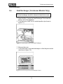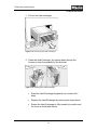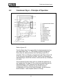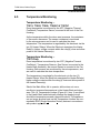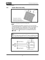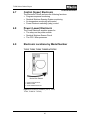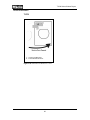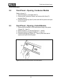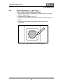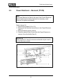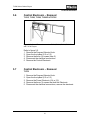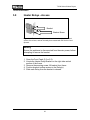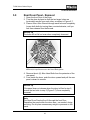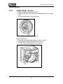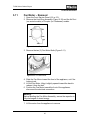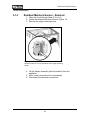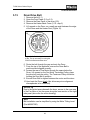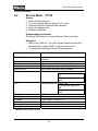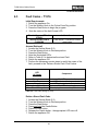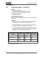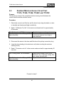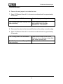
1
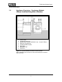
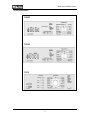
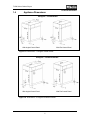
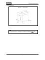
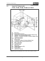
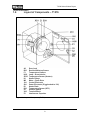
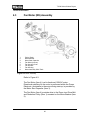
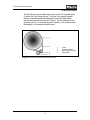
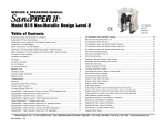
TECHNICAL INFORMATION
T1500 Series Clothes Dryers
© 2003 Miele
T1500 Series Clothes Dryers - Table of Contents
1.0 CONSTRUCTION & DESIGN
1.1 Appliance Overview - Vented
1
1.2 Appliance Overview – Condenser Models
2
1.3 Controls Overview
3
1.4 Appliance Dimensions
5
1.5 Layout of Components – T1515, T1520, T1526, T1565C & T1570C
7
1.6 Layout of Components – T1576
8
2.0 INSTALLATION
2.1 Electrical Requirements
9
2.2 Plumbing Information – Condenser Models
10
2.3 Installation Procedures
10
3.0 COMMISSION and OPERATION
3.1 General Operation – T1515, T1520, T1526, T1565C & T1570C
11
3.2 Additional Function Pushbuttons – T1515, T1520, T1526, T1565C & T1570C
11
3.3 General Operation – T1576
12
3.4 Program Option Buttons - T1576
12
3.5 Condenser Drawer (Condenser Models Only)
13
3.6 Heat Exchanger (Condenser Models Only)
14
4.0 DESCRIPTION of FUNCTION
4.1 Vented Dryer – Principle of Operation
17
4.2 Condenser Dryer – Principle of Operation
18
4.3 Fan Motor Assembly
20
4.4 Residual Moisture Sensing
22
4.5 Temperature Monitoring
23
4.6 Heater Bank Assembly
24
4.7 Control (Upper) Electronic
25
4.8 Power (Lower) Electronic
25
4.9 Electronic Locations by Model Number
25
5.0 SERVICE and MAINTENANCE
5.1 Lid – Removal
27
5.2 Front Panel – Opening, Condenser Models
28
5.3 Front Panel – Opening, Vented Models
28
5.4 Power Electronic – Removal (T1515, T1520, T1526, T1565C & T1570C)
29
5.5 Power Electronic – Removal (T1576)
30
5.6 Control Electronic – Removal (T1515, T1520, T1526, T1656C & T1570C)
31
5.7 Control Electronic Removal (T1576)
31
5.8 Heater Relay – Access
32
5.9 Rear Drum Panel – Removal
33
5.10 Heater Bank – Access
34
5.11 Fan Motor – Removal
35
5.12 Condenser Assembly – Removal
36
5.13 Condenser Fan – Removal
37
5.14 Residual Moisture Sensor – Removal
38
5.15 Drum Drive Belt – Replacement
39
6.0 FAULT DIAGNOSIS
6.1 Service Mode (T1515, T1520, T1526, T1565C & T1570C)
41
6.2 Service Mode (T1576)
42
6.3 Fault Codes (T1576)
43
6.4 Programming Mode (T1576)
44
6.5 Residual Moisture Sensor Circuit Test (T1515, T1520, T1526, T1565C & T1570C)
45
6.6 Residual Moisture Sensor Circuit Test (T1576)
47
6.7 Dryer Takes too Long to Dry Clothes
49
6.8 Residual Moisture Sensing Inoperative
49
6.9 Dryer Door Keeps Popping Open (except T1576)
59
6.10 Water Leaks – Condenser Dryer
50
6.11 Noise – Light Repetitive Clicking
50
6.12 T1576 Dryers shuts down after less than 1 minute of operation
50
6.13 Rumbling Sound While in Operation
50
T1500 Series Clothes Dryers – List of Figures
1-1 Overview T1500 Series Dryer
1
1-2 Typical Installation
2
1-3 Control Panels (T1515, T15120 & T1526)
3
1-4 Control Panels (T1565C, T1570C & T1576)
4
1-5 Appliance Dimensions (5 Kilogram - Vented
5
1-6 Appliance Dimensions (5 Kilogram - Condenser)
5
1-7 Appliance Dimensions (6 Kilogram)
6
1-8 Layout of Components (T1515, T1520, T1526, T1565C & T1570C)
7
1-9 Layout of Components (T1576)
8
3-1 Opening the Cover to the Heat Exchanger
14
3-2 Positioning the Heat Exchanger Levers
14
3-3 Removing the Heat Exchanger
15
3-4 Cleaning the Heat Exchanger
15
4-1 Vented Dryer Airflow
17
4-2 Condenser Dryer Airflow
18
4-3 Motor Assembly
20
4-4 Drum Drive Belt and Reduction Pulley
21
4-5 Heater Bank Assembly
24
4-6 Heater Circuit
24
4-7 Electronic Locations (T1515, T1520, T1526, T1565C & T1570C)
25
4-8 Electronic Locations (T1576)
26
5-1 Lid Removal and Front Panel Access
27
5-2 Removing the left section of the fascia panel
28
5-3 Securing screw for Power Electronic
29
5-4 Removing the Power Electronic on the T1576
30
5-5 Control Electronic Removal
31
5-6 Heater Relay Bracket
32
5-7 Drum positioned for Access to Bearing Bolts
33
5-8 Heater Bank Cover Retaining Bolts
34
5-9 Heater Bank Removal
34
5-10 Vent Ring Assembly
35
5-11 Fan Motor Bolts
35
5-12 Bottom Cover Screws
37
5-13 Condenser Fan Screws
37
5-14 Residual Moisture Sensor Mounting
38
5-15 Positioning the Drum for Drive Belt Installation
39
T1500 Series Clothes Dryers – List of Tables
6-1 Service Mode Functions (T1515, T1520, T1526, T1565C & T1570C)
41
6-2 Service Mode Functions (T1576)
42
6-3 Fault Code Storage (T1576)
43
6-4 Programming Mode Values (T1576)
44
T1500 Series Clothes Dryers
Technical Information
1.0
Construction and Design
1.1
Appliance Overview – Vented
(Typical 5 Kilogram Vented Model Shown)
1 Supply Cable / Plug
2 Control Panel
3 Drum Door
4 Exhaust Connection (right, left & rear 5k vented)
5 Adjustable Legs
(left & rear 6k vented)
Figure 1-1: Appliance Overview T1500 series Dryer (Vented 5 K Model Shown)
1
T1500 Series Clothes Dryers
Technical Information
1.2
Appliance Overview – Condenser Models
(Shown Installed Along Side a Washer)
1.
2.
3.
4.
5.
6.
7.
8.
Control Panel
Condenser Drain Hose
Washer Drain Hose (for clarification only – not part of Dryer)
Electrical Cord and Plug
Condensed Water Drawer
Drum Door
Adjustable Legs
Stand Pipe
Figure 1-2: Typical installation with Miele Clothes Washer.
Note: Condenser hose is placed into the same stand pipe the washer
drain hose uses.
2
T1500 Series Clothes Dryers
Technical Information
1.3
Controls Overview
T1515
5 Kilogram Vented
T1520
5 Kilogram Vented
T1526
6 Kilogram Vented
Figure 1-3: Control Panels for model numbersT1515, T1520 and T1526.
3
T1500 Series Clothes Dryers
Technical Information
T1565C
T1570C
T1576
Figure 1-4: Control Panels for model numbersT1565C, T1570C and T1576.
4
T1500 Series Clothes Dryers
Technical Information
1.4
Appliance Dimensions
5Kilogram – Vented Models
With Angled Control Panel
With Flat Control Panel
Figure 1-5: Dimensions – 5 kilogram vented models
5Kilogram – Condenser Models
With Angled Control Panel
With Flat Control Panel
Figure 1-6: Dimensions – 5 kilogram condenser models
5
T1500 Series Clothes Dryers
Technical Information
6Kilogram – Vented Models
Figure 1-7: Dimensions 6 kilogram – Vented Models
Note
At the present time, a 6 kilogram condenser model does NOT exist.
6
T1500 Series Clothes Dryers
Technical Information
1.5
Layout of Components
T1515, T1520, T1526, T1565C & T1570C
A2
B3/1
B8
C2
C5
F1
H3/6
K1
M2
M13
M5
1N1
2N1
R1
R30
S1
X3/1
Z1
Door Lock
Residual Moisture Sensor
Float Switch (Condensate Water) (Condenser Models Only)
Capacitor – Fan (Condenser Models Only)
Capacitor – Condensate Fan Motor (Condenser Models Only)
Temperature Limiters
Lamp – Drum Interior
Heater Relays
Condensate Fan Motor (Condenser Models Only)
Condensate Pump (Condenser Models Only)
Motor – Drum Drive
Control Electronic
Power Electronic
Heater Bank
Temperature Sensor (NTC)
Selector Switch
Terminal Block
Interference Capacitor
Figure 1-8: Layout of Components (T1515, T1520, T1526, T1565C & T1570C).
7
T1500 Series Clothes Dryers
Technical Information
1.6
Layout of Components – T1576
A2
B3/1
F1
H3/6
2R30
K1
M5
1N1
2N1
R1
R30
S1
X3/1
Z1
Door Lock
Residual Moisture Sensor
Temperature Limiters
Lamp – Drum Interior
Temperature Sensor (Heaters)
Heater Relays
Motor – Drum Drive
Control Electronic
Power Electronic (Piggybacked to 1N1)
Heater Bank
Temperature Sensor (NTC)
Selector Switch
Terminal Block
Interference Capacitor
Figure 1-9: Layout of Components (T1576)
8
T1500 Series Clothes Dryers
Technical Information
2.0
Installation
Do not drink the condensed water.
Keep the area around the air intake (Toekick) and surrounding
areas free from lint, dust and dirt. This area should not be
blocked (i.e. Toekick) this will prevent sufficient intake of air and
effect appliance operation.
Do not reach into the Dryer if the Drum is moving.
The appliance should be level to ensure proper operation.
A Dryer can be placed on top of a Miele Washer; for a stacked
installation. An approved Miele stacking kit must be used.
2.1
Electrical Requirements
120/240 (208) Volt, 60Hz., 15 Amp breaker
Dryer is equipped with a 4 wire power cord equipped with a
NEMA 14-30 plug, for connection to a NEMA 14-30 receptacle.
Note
If you do not have a dedicated 15 Amp circuit for this appliance, but
have a NEMA 14-20 or NEMA 14-30, 240V, 30 Amp outlet, you
may be able to use a Miele “Easy Installation Kit” to simplify the
electrical connection. For further information refer to Electrical
Information pages in the Installation Manual.
Do not cutoff / remove the Plug from the Power Cord.
9
T1500 Series Clothes Dryers
Technical Information
2.2
Plumbing Information - Condenser Models
On Condenser Model Dryers the option exist to have the
condensed water exit the appliance via a Drain Line. A suitable
drain system (i.e. standpipe) is required for this option.
Maximum Drain Hose length: 10 ft
Maximum Drain height: 4 ft.
All Condenser Model Dryers come supplied with the following
accessories to add the Drain Line option. Please do not discard the
parts during an installation as they may be utilized at a later date.
- 6 ft Drain Hose
- Hose Clamp
- Hose Elbow
2.3
Installation Procedure
1. Position Dryer at install location and level using the legs on the
bottom of the appliance. The metal frame of the appliance
provides the ideal location to place a level. Ensure appliance is
as level.
2. Connect Power and perform operational check.
Note
If Dryer is to be installed in combination with a Stacking Kit and
Clothes Washer, the Washer must be positioned and installed first.
If an optional Laundry Stand is being installed - refer to the
Accessories section of the Installation Manual for the procedure on
installing the stand.
Refer to the Miele Installation Manual for further installation
information and procedures.
10
T1500 Series Clothes Dryers
Technical Information
3.0
Commission and Operation
3.1
General Operation – T1515, T1520, T1526,
T1565C and T1570C
1.
2.
3.
4.
5.
6.
3.2
Turn on the Dryer.
Press the Door Button to open the Door.
Place laundry into the appliance
Select a program
Select option(s) – as desired.
Press the Start Button.
Additional Function PushButtons – T1515,
T1520, T1526, T1565C and T1570C
Door
Opens the Door or can be used to cancel a program (does not stay
pushed in).
ON / OFF
Turns the appliance On/Off, and can be used to cancel a program.
Buzzer
Enables the buzzer, when the anti-crease stage of the program is
reached.
Load size - Full / Half
To dry a standard size load or more at peak efficiency, select press
this option before starting a program.
Low Temperature.
Utilizes lower drying temperatures for delicate fabrics.
Start
Starts the selected program (does not stay pushed in).
11
T1500 Series Clothes Dryers
Technical Information
3.3
General Operation – T1576
1.
2.
3.
4.
5.
6.
Turn on the Dryer.
Press the Door Button to open the Door.
Place laundry into the appliance
Select a program
Select option(s) – as desired.
Press the Start Button.
Service Tip
The Heaters are not powered during the initial start of a program.
The Heater are powered, after the drum reverses direction.
3.4
Program Option Buttons – T1576
Low Energy (with Cottons Program)
Normal heater operation with a lower temperature
Turbo (with Cottons Program)
Normal heater operation with a higher temperature
Gentle
Uses a lower temperature and extended program time for care of
delicate fabrics.
Buzzer
Enables the buzzer, when the anti-crease stage of the program is
reached.
12
T1500 Series Clothes Dryers
Technical Information
3.5
Condenser Drawer (Condenser Models Only)
General Information
Depending on the installation, condensed water is either pumped to
an on-site drain, or collected in the Condensed Water Drawer.
The Condensed Water Drawer holds approximately one (1) gallon
of water. The water should be emptied from the drawer after each
program completes. Should the container be full (or become filled
during operation) the following occurs:
The “Empty out container” indicator illuminates
The buzzer sounds
The drying program stops and enters the cooling down cycle
To empty the Condensed Water Drawer:
1. Hold the cap open while emptying the Water Drawer.
2. Drain all water
3. Install the Water Drawer back into the appliance. Ensure the
locks into place.
Warning
The condensed water is not suitable for consumption.
13
T1500 Series Clothes Dryers
Technical Information
3.6
Heat Exchanger (Condenser Models Only)
Note
The heat exchanger should be cleaned at least twice a year.
1. Open the Door. Locate the Heat Exchanger Cover near the
bottom / left of the appliance.
2. Turn the lever so that it is in a vertical position (as shown in
figure 3-1).
Figure 3-1: Opening the cover to the Heat Exchanger
3. Remove the cover.
4. Turn both levers on the heat exchanger so that they are vertical
(as shown in figure 3-2).
Figure 3-2: Positioning the Heater Exchanger Levers
14
T1500 Series Clothes Dryers
Technical Information
5. Pull out the heat exchanger.
Figure 3-3: Removing the Heat Exchanger
6. Clean the Heat Exchanger, by running water through the
louvers to clean the assembly of lint and dust.
Figure 3-4: Cleaning the Heat Exchanger
Stand the Heat Exchanger lengthwise on a towel until it
dries.
Replace the Heat Exchanger by reversing the steps above.
Ensure the Heat Exchanger is fully seated into position and
the cover is closed and locked.
15
T1500 Series Clothes Dryers
Technical Information
16
T1500 Series Clothes Dryers
Technical Information
4.0
Description of Function
4.1
Vented Dryer – Principle of Operation
1.
2.
3.
4.
5.
6.
7.
8.
9.
10.
Door
Filter
Output from Filter
Fan Motor
NTC Sensor (13 K.Ohms @ 750F)
Drum
Warmed Drying Air
Drying Load
Heater Bank
Vent Output
Figure 4-1: Vented Dryer Airflow
Refer to figure 4-1.
The Fan Motor (Item 4) is responsible for drawing heated air from
the Heater Bank (Item 6). The heated air passes through the Drum
(Item 9), where moisture from the Drying Load (7) is absorbed. The
air is filtered as it passes through the Filter (Item2) located in the
Front Door (Item 1). The flow continues through the Fan Motor
(Item 4) and exits via the Vent Output (Item 5).
17
T1500 Series Clothes Dryers
Technical Information
4.2
Condenser Dryer – Principle of Operation
1. Condensed Water Drawer
2. Door
3. Filter
4. Filter Screens
5. Fan Motor
6. Condensed Water
7. Condenser Unit
8. Condensate Fan
9. Cool air Intake
10. Condensate Pump
11. Heater Bank
12. Drying Load
13. Heated Dry Air
14. Drum
Figure 4-2: Condenser Dryer Airflow
Refer to figure 4-2.
The Fan Motor (Item 5) is responsible for drawing heated air from
the Heater Bank (Item 11). The heated air passes through the
Drum (Item14), where moisture from the Drying Load (12) is
absorbed. The air is filtered as it passes through Filters (Items 3 &
4). Air continues through the Fan Motor (Item 5) and through the
Heat Exchanger, where the moisture content (in the air) condenses
into water.
The Condenser System draws air from outside the appliance via
the Condensate Fan (Item 8). The outside air passes through the
Heat Exchanger in a 900 direction from the drying air. The
temperature difference between the two allows moisture
(condensation) to form on the Heat Exchanger. As the moisture
level increases, water droplets collect in a trough.
18
T1500 Series Clothes Dryers
Technical Information
When the condensed water accumulates to a specific value the
Condensate Float Switch actuates. The Electronic energizes the
Condensate Pump (Item 10) and the water is pumped to the
Condenser Drawer (Item 1). Should the Condenser Drawer (Item 1)
become full prior to the end of a cycle the “Empty Out Container”
LED is illuminated and the program stops.
Note
Condenser model Dryers can be configured with an optional drainline. With this configuration the condensed water is pumped directly
into the drain, therefore emptying the Condenser Drawer is not
necessary.
19
T1500 Series Clothes Dryers
Technical Information
4.3
Fan Motor (M5) Assembly
1
2
3
4
5
6
7
8
Pulley / Belts
Motor Bracket
Motor Start Capacitor
Fan Motor (120VAC)
Fan Housing Cover
Fan Impeller
Fan Housing
Motor Assembly Slide Track
Figure 4-3: Motor Assembly
Refer to Figure 4-3.
The Fan Motor (Item 4) is a bi-directional 120VAC motor.
Directional switching for the motor is performed within the Power
Electronic. Assistance to the motor during start-up; is provided by
the Motor Start Capacitor (Item 3).
The Fan Motor (Item 4) provides drive to the Drum via a Drive Belt
and Reduction Pulley (Item 1) mounted on the Motor Bracket (Item
2).
20
T1500 Series Clothes Dryers
Technical Information
The Fan Motor also provides direct drive to the Fan Impeller (Item
6) within the Fan Housing (Item 7). As the Fan Impeller rotates,
airflow is created and draws heated air from the Heater Bank,
across the drum and through the Filter(s). The air exiting the Fan
Housing (Item 7), is routed to the vent system; or through the Heat
Exchanger on Condenser Model Dryers.
1
2
3
4
Figure 4-4: Drum Drive Belts and Reduction Pulley
21
Drum
Drum Drive Belt
Belt (Motor to Pulley)
Motor (M5)
T1500 Series Clothes Dryers
Technical Information
4.4
Residual Moisture Sensing
There are two variables that determine the Dryer run time; initial
moisture content in the laundry and the program selected.
At the beginning of the cycle, the moisture content within the
laundry is measured by the Residual Moisture Sensor. This value is
used by the electronic to calculate the approximate program
duration.
During drying, the level of moisture within the laundry decreases.
And is reflected by the status of the Drying Stage Reached LED’s.
When the moisture within the laundry reaches the selected program
value the Dryer enters the cooling down stage, followed by the
Anti-Crease mode.
Important
The electronic limits all moisture sensing programs to a maximum
duration of 240 minutes. Should 240 minutes be reached, the
cooling down stage is initiated; however the Anti-Crease feature is
skipped when this occurs.
The Cooling Down LED remains illuminated until the appliance is
shut off - via the On/Off Button.
22
T1500 Series Clothes Dryers
Technical Information
4.5
Temperature Monitoring
Temperature Monitoring –
T1515, T1520, T1526, T1565C & T1570C
Drum temperature is monitored by the NTC (Negative Thermal
Coefficient) Temperature Sensor; mounted in the front of the Fan
Housing.
As the temperature within the drum area increases, the resistance
of the sensor decreases. The sensor resistance is monitored
by the microprocessor and is used to calculate the drum
temperature. The temperature is regulated by the electronic via the
two (2) Heater Relays. When the Electronic energizes the Heater
Relay(s), higher voltage contacts within the relay(s) close and allow
power to the Heater Element(s).
Temperature Monitoring –
T1576 Only
Drum temperature is monitored by two NTC (Negative Thermal
Coefficient ) Temperature Sensors. One Sensor is mounted in the
Heater Bank Assembly, the second Sensor is mounted in the Fan
Housing. Both sensors are monitored by the microprocessor; and
are used to calculate the drum temperature.
The temperature is regulated by the electronic via the two (2)
Heater Relays. When the Electronic energizes the Heater Relay(s),
higher voltage contacts within the relay(s) close and allow power to
the Heater Element(s).
Should the Main Motor fail to operate, airflow does not occur;
resulting in increased temperatures in the Heater Bank and drum
area. Two (2) Temperature Limiters (Figure 4-5, Item 1) are affixed
to the Heater Bank and electrically interrupt the heating circuit
should the temperature exceed a preset threshold. The appliance
can no longer produce heat; as the Temperature Limiters are nonresettable SOD (Single Operation Device) devices in accordance
with product approvals.
23
T1500 Series Clothes Dryers
Technical Information
4.6
Heater Bank Assembly
1 – Temperature Limiters (2)
2 - Temperature Sensor (NTC)
(T1576 Only) (100k.Ohm@ 750F)
Figure 4-5: Heater Bank Assembly (T1576 shown; all other T1500 series dryers
do not have a Temperature Sensor in the Heater Bank)
The Heater Bank Assembly is comprised of two (2) electrically
isolated Heater Elements. Temperature Limiters are secured to the
top of the assembly and are electrically in series to the Heater
Elements. The Temperature Limiters are non-resettable SOD
(Single Operation Device) devices in accordance with product
approvals.
Note
The T1576 Dryer has an additional NTC sensor installed at the top
of the Heater Bank Assembly, next to the Thermostats (Figure 5).
Temperature Limiters
Figure 4-6: Heater Circuit
24
T1500 Series Clothes Dryers
Technical Information
4.7
Control (Upper) Electronic
The Electronic Control performs the following functions:
Program sequence monitoring
Residual Moisture Sensing System monitoring
Air temperature monitoring and control
Power Electronic switching (relay) control
4.8
Power (Lower) Electronic
The Power Electronic supplies power for:
The relays on the power module
Residual Moisture Sensor Circuit
The CPU / Microprocessor
4.9
Electronic Locations by Model Number
T1515, T1520, T1526, T1565C & T1570C
1 – Control Unit Electronic
2 – Ribbon Cable
3 – Power Module Electronic
Figure 4-7: Electronic Locations (T1515, T1520,
T1526, T1565C & T1570C)
25
T1500 Series Clothes Dryers
Technical Information
T1576
1- Control Unit Electronic
2- Power Module Electronic
Figure 4-8: Electronic Locations on T1576
26
T1500 Series Clothes Dryers
Technical Information
5.0
Service and Maintenance
Note
Service and repair work should only be performed by qualified
personnel; in accordance with applicable codes.
Warning
The appliance should be unplugged from the power source before
any service and /or maintenance procedures are performed.
5.1
Lid - Removal
Figure 5-1: Lid Removal and Front Panel Access
Refer to figure 5-1.
1. Remove the screws from the side edges of the lid (Item 1).
2. Lift the lid at the front, slide it towards the rear and lift to remove.
27
T1500 Series Clothes Dryers
Technical Information
5.2
Front Panel – Opening, Condenser Models
Refer to figure 5-1.
1. Remove the four (4 )screws (Item 3).
2. Remove the Condenser Drawer and unscrew the three (3)
screws (Item 4).
3. Press the spring clip (Item 2) down with the lid opener and open
the front panel.
5.3
Front Panel – Opening, Vented Models
1. Remove the left section of the fascia panel using a lid opener
(Figure 5-2 – Item 1).
2. Remove the four (4 ) screws (Figure 5-1 – Item3).
3. Remove the two (2) screws (Figure 5-1 – Item 4)
4. Press the spring clip (Figure 5-1 – Item 2) down with the lid
opener and open the front panel.
Figure 5-2: Removing the left section of the fascia panel.
28
T1500 Series Clothes Dryers
Technical Information
5.4
Power Electronic – Removal
T1515, T1520, T1526, T1565C and T1570C
1. Open the front Door and remove the screw near the 4 o’clock
position (Figure 5-3).
2. Open the Front Panel (5.2 or 5.3)
3. Slide the Power Module Electronic upward to release from the
frame.
4. Disconnect the electrical connections and remove the
electronic.
Figure 5-3: Securing screw for Power Electronic on the
T1515, T1520, T1526, T1565C and T1570C model Dryers.
29
T1500 Series Clothes Dryers
Technical Information
5.5
Power Electronic – Removal (T1576)
Note
The Power Electronic is fitted to the rear of the Control Electronic.
Should replacement of either electronic be necessary, each
Electronic is replaced individually.
Refer to figure 5-4.
1. Open the front panel (5.2 or 5.3).
2. Disconnect the electrical connections to the Power Electronic
(Item 1).
3. Remove the fixing screw (Item 8).
4. Press the retainer (Item 2) and slide the Power Electronic to
remove it from the holder (Item 5).
Service Tip
Screw (Figure 5-4, Item 8) is shorter and should only be used to
secure the power module.
Figure 5-4: Removing the Power Electronic on the T1576 Dryer.
30
T1500 Series Clothes Dryers
Technical Information
5.6
Control Electronic – Removal
T1515, T1520, T1526, T1565C & T1570C
Figure 5-5: Control Electronic removal on T1515, T1520, T1526, T1565C
and T1570C Dryers.
Refer to figure 5-5.
1. Remove the Program Selector Knob.
2. Open the front panel (5.2 or 5.3)
3. Remove the three (3) screws (Item 2).
4. Disconnect the electrical connections
5. Remove the Control Electronic.
5.7
Control Electronic – Removal
T1576
1.
2.
3.
4.
5.
Remove the Program Selector Knob.
Open the front panel (5.2 or 5.3)
Remove the Power Electronic (5.4 or 5.5)
Remove the three (3) screws that hold the Electronic.
Disconnect the electrical connections; remove the electronic.
31
T1500 Series Clothes Dryers
Technical Information
5.8
Heater Relays - Access
Bracket
Bracket Screw
Figure 5-6: The Heater Relay Bracket is attached to the right side vertical
section of the frame, and can be easily be accessed with the Service Panel
Opened.
Warning
Ensure the appliance is disconnected from the main power, before
attempting to remove the bracket.
1. Open the Front Panel (5.2 or 5.3).
2. Locate the Heater Relay Bracket on the right side vertical
section of the frame.
3. Remove the securing screw; lift bracket from frame.
4. Position bracket to allow access to the Relay(s).
5. Slide each Relay from the bracket to release.
32
T1500 Series Clothes Dryers
Technical Information
5.9
Rear Drum Panel - Removal
1. Open the front Door of the Dryer.
2. Turn the drum by hand so that the two larger holes are
horizontally across from each other; as shown in Figure 5-7.
3. Place a 5mm. Allen Wrench through each hole and completely
loosen both bolts by turning them counterclockwise, until you
feel them release from the threads.
Service Tip
The bolts will not fall out even when completely loosened.
Figure 5-7: Drum positioned with the two largest holes
horizontal; this permits access to the Drum Bearing Bolts.
4. Remove the six (6) Allen Head Bolts from the perimeter of the
rear panel.
5. From inside the drum, push the drum upward and pull the rear
panel outward to remove.
Service Tip
If the panel does not release when the drum is lifted in step 5;
ensure the two bolts in step 3 (Figure 5-7) 8 are completely
loosened.
Note
The Rear Drum Panel will not fit through the front Door.
Reposition the panel within the drum area – as needed, during
servicing. Do not place unnecessary weight or pressure on the
panel.
33
T1500 Series Clothes Dryers
Technical Information
5.10
Heater Bank - Access
1. Remove the Rear Drum Panel (5.9)
2. Remove the three (3) bolts from the Heater Bank Cover (Figure
5-8).
3. Lift the Heater Bank Cover to remove.
Figure 5-8: Heater Bank Cover retaining bolts.
Refer to figure 5-9.
4. Unscrew the heater bank retainers (Items 1 and 2).
5. Disconnect the electrical connections (Item 3).
6. Pull the Heater Bank upwards out of its duct.
Figure 5-9: Heater Bank removal.
34
T1500 Series Clothes Dryers
Technical Information
5.11
Fan Motor – Removal
1. Open the Front Service Panel (5.2 or 5.3).
2. Remove the Vent-Ring Assembly (Figure 5-10) and the Air Duct
(on vented models) or Coupler (on Condenser) models.
Figure 5-10: Vent Ring Assembly
3. Remove the two (2) Fan Motor Bolts (Figure 5-11).
Figure 5-11: Fan Motor Bolts.
4. Slide the Fan Motor toward the front of the appliance, out if the
locking track.
5. Lift the Fan Motor; tilting it slightly upward toward the back to
release it from the belt.
6. Position the Fan Motor toward the front of the appliance;
disconnect the electrical connection.
Warning:
Before handling the Fan Motor Assembly, ensure the capacitor is
fully discharged of stored energy.
7. Lift the motor from the appliance to remove.
35
T1500 Series Clothes Dryers
Technical Information
5.12
Condenser Assembly – Removal
Service Tip
To access to The Condenser Pump and/or Float Switch; the
Condenser Assembly must be removed from the appliance.
1. Remove the Coupler between the Fan Motor Housing and the
Condenser Assembly.
2. Remove the Fan Motor (5.11)
3. Remove the Heat Exchanger form the Condenser (3.6).
4. Disconnect the electrical connections.
5. Slide the Condenser Assembly toward the front of the appliance
and lift to remove.
36
T1500 Series Clothes Dryers
Technical Information
5.13
Condenser Fan – Removal
1. Lay the appliance on it’s back
2. Remove the four (4) screws that secure the Bottom Cover
(Figure 5-12) and lift the cover to remove it from the appliance.
Figure 5-12: Bottom Cover Screws.
Figure 5-13: Condenser Fan Screws.
3. Remove the four (4) screws that secure the Condenser Fan to
the Condenser Assembly (Figure 5-13).
4. Disconnect the electrical connection.
5. Lift the Condenser Fan to remove it from the Condenser
Assembly.
37
T1500 Series Clothes Dryers
Technical Information
5.14
Residual Moisture Sensor - Removal
1. Open the Front Service Panel (5.2 or 5.3).
2. Locate the Residual Moisture Sensor (Figure 14)
3. Remove the single retaining screw.
Figure 5-14: The Residual Moisture Sensor is attached to
the frame near the 2 o’clock position with a single retaining
screw.
4. Lift the Sensor Assembly (with the bracket) from the
appliance.
5. Note / mark wire positions for re-assembly.
6. Disconnect the electrical connections.
38
T1500 Series Clothes Dryers
Technical Information
5.15
Drum Drive Belt
1.
2.
3.
4.
5.
Remove the lid (5.1)
Open the Front Panel (5.2 or 5.3).
Remove the Rear Panel of the drum (5.9).
Remove the Heater Bank Cover (5.10 - step 2)
Lift upward on the Drum, so a small gap exist between the edge
of the Drum and the Heater Duct (Figure 15).
Figure 5-15: Positioning the drum to form
a gap. This is necessary to routing the
Drum Drive Belt around the drum.
6. Route the belt through the gap and onto the Drum.
7. From the top of the appliance, ensure the Drum Belt is
positioned and aligned correctly.
8. Access the rear of Fan Motor through the space below the
Drum. Lift upward on the Fan Motor Tensioning Pulley, place
the drive belt onto the pulley. The Tensioner Pulley should be
holding the Dum Belt in position.
9. Ensure Drum Belt is aligned between the motor and the drum.
10. Hand spin the Drum slowly (this allows any minor alignment
discrepancies to be corrected).
Service Tip
Due to the limited space beneath the drum, access to the rear area
of the Fan Motor is via the space along the inner section of the right
side panel (above the fan motor housing).
Note
Belt installation can be simplified by using the Miele “Fitting Lever”
(Part #05057330).
39
T1500 Series Clothes Dryers
Technical Information
40
T1500 Series Clothes Dryers
Technical Information
6
Fault Diagnosis
6.1
Service Mode –
T1515, T1520, T1526, T1565C & T1570C
Access
1. Switch Off the appliance.
2. Release all Push-Buttons.
3. Turn the Program Selector Switch to the Finish/Start (12
o’clock) position.
4. Switch the appliance On.
5. Press and release the Low Temperature Button (or Load Size
Button – depending on the model number) 3 times in quick
succession within 10 seconds.
Acknowledgement Indicator
The Drying LED flashes to show the Service Mode is activate.
Navigation
Refer to Table 6-1. Turn the Program Selector Knob to the desired
position, then press START.
To exit the Service Mode, Switch Off the appliance.
Selector Switch Position
Finish / Start
Cotton Extra Dry
Cottons Normal +
Cottons Normal
Cottons Hand Iron
Cottons Hand Iron
Cotton Appliance Iron
15 minutes Cool Air
20 minutes Warm Air
Permanent Press Hand Iron
Permanent Press Normal +
Function
Buzzer pushButton test
Heater on
Drum drives left (vented models only)
Buzzer Activated
Drum drives right (vented models only)
Condenser Fan
(Condenser models only
Condensate Pump
(Condenser models only)
See Residual Moisture Sensor Test
See Residual Moisture Sensor Test
LED test (LED’s illuminated)
Dryer type: Continuous Tone = Vented,
Intermittent Tone = Condenser
Table 6-1: Service Mode Functions (T1515, T1520, T1526, T1565C and T1570C).
41
T1500 Series Clothes Dryers
Technical Information
6.2
Service Mode – T1576
Access
1. Switch Off the appliance.
2. Turn the Program Selector Switch to 12 o’clock.
3. Press and hold the Gentle and Start Buttons.
4. Switch the appliance On.
5. Release the Buttons
Acknowledgement Indicator
The Drying LED flashes to show the Service Mode is activate.
Navigation
Refer to the Table 6-2. Turn the Program Selector Knob to the
desired position; press START to activate the function.
To exit the Service Mode, Switch Off the appliance.
Selector switch position
Press Start to activate…
Extra Dry
Main motor operates 10 seconds in each
direction
Vacant
One heater and Main motor operates
Main motor operates
Both heater and main motor operates
Residual moisture sensor Test.
Cooling down lights up =
OK
Cooling down flashes =
fault
Residual moisture sensor Test.
Cooling down lights up =
OK
Cooling down flashes =
fault
LED test
Button test.
Fault Codes – Refer to 6.3
Vacant
Vacant
Vacant
Normal +
Normal
Hand iron ,
Hand iron , ,
Rotary iron
Fluff
20 mins.
Line Dry
Woolens
Perma Press Hand iron
Perma Press Normal
Perma Press Normal+
Table 6-2: Service Mode Functions
42
T1500 Series Clothes Dryers
Technical Information
6.3
Fault Codes – T1576
Initial Requirements
1. Switch the appliance On.
2. Turn the Selector Knob to the Cotton Extra Dry position.
3. Press the Start Button to begin the program.
4. Note the status of the Anti-Crease LED.
No Fault Stored
The Anti-Crease LED is lit
STEADY
The Anti-Crease LED is
FLASHING
Fault Stored – Proceed to Access
steps below
Access (Retrieval)
1. Access the Service Mode (6.2)
2. Turn the Selector Knob to Woolens position.
3. Press the Start Button
4. Note the illuminated LED’s.
5. Refer to Table 6-3 to determine the stored Fault.
6. Switch the appliance Off.
7. Perform the necessary service steps to rectify the cause of the
fault; proceed to the “Delete a Stored Fault Code” below.
LED
Lit Steady
Component
Rotary Iron
Hand Iron
Normal
Rotary Iron & Hand Iron
Normal and Rotary Iron
Fan NTC open circuit
NTC at heater bank open circuit.
NTC at heater bank short circuit
Fan NTC short circuit
Max drying time exceeded, (180 minutes)
Table 6-3: Fault Code Storage (T1576)
Delete a Stored Fault Code
1. Access the Service Mode (6.2)
2. Turn the Selector Knob to Woolens position.
3. Press the Start Button.
4. Press and hold the Gentle Button.
5. Press the Start button.
6. Release the Gentle button - the appropriate LED turns off.
7. Switch the appliance Off.
43
T1500 Series Clothes Dryers
Technical Information
6.4
Programming Mode – T1576 Only
Access
1. Switch Off the appliance.
2. Turn the Program Selector Switch to 12 o’clock.
3. Press and hold the Gentle and Buzzer Buttons.
4. Switch the appliance On.
5. Release the Buttons
Acknowledgement Indicator
The Drying & Cooling Down LED’s flash to show the Service Mode
is activate.
Navigation
Refer to the Table 6-4. Turn the Program Selector Knob to the
desired position; press START to activate the function.
The programmed value is indicated by the status of the Rotary
Iron LED. Press Start to toggle between the options.
To store the selected setting, switch Off the appliance while the
Program Selector Knob is in the desired position and the Rotary
Appliance Iron is displaying the desired setting.
Selector Switch
Position
Cottons Extra Dry
Cottons Normal
Cottons Hand Iron
Function
Residual
Moisture Level
Memory
Function
Anti-Crease
Action
* Factory Setting (Do Not Adjust)
Table 6-4: Program Mode Values (T1576)
44
Option(s)
Standard*
Reduced
No*
Yes
No*
Yes
Status of
Rotary LED
Off
On
Off
On
Off
On
T1500 Series Clothes Dryers
Technical Information
6.5
Residual Moisture Sensor Circuit Test
T1515, T1520, T1526, T1565C and T1570C
Purpose
This serves as a test of the complete moisture sensing circuit between the
control module and the moisture sensor.
Procedure
1. Electrically connect one lifter bar and the drum body using clip leads or a wire
to simulate wet laundry and high conductivity.
2. Select “15 Minutes Cool Air” In the service mode and wait for approximately
60 seconds.
The “Cooling down” LED Illuminates
The “Cooling down” and “Drying” LEDs
flash alternately
Circuit Is In proper working order
(Resistance of connection between
controls and sensors Is too high or
open circuited).
3. Disconnect the wires to the drum and lifter bar at the pickup connection plug.
4. Jump the wires leading to the electronic unit (short circuiting the moisture
sensing circuit).
5. Select “15 minutes cool air” In the service mode and wait for approximately 60
seconds.
The “Cooling down” LED Illuminates
The “Cooling down” and “Drying” LEDs
flash alternately
Check circuit outside of the Control
Electronic. (e.g.~ slip rings, wiring, lifter
bars, sensor contacts etc).
Replace the Control Electronic.
Proceed to step 6.
45
T1500 Series Clothes Dryers
Technical Information
6. Remove the wire jumper from inside the drum.
7. Select “20 Minutes Warm Air” in the service mode and wait for approximately
60 seconds.
The “Cooling down” LED Illuminates
Circuit is In proper working order
The “Cooling down” and “Drying” LEDs
flash alternately
Circuit defective (Lifter bars
drum partially short-circuited.
Resistance is < 50 M.Ohms
8. Disconnect the wires to the drum and lifter bars at the pickup connection plug.
9. Select “20 Minutes Warm Air” in the service mode and wait for approximately
60 seconds.
The “Cooling down” LED Illuminates
The “Cooling down” and “Drying” LEDs
flash alternately
Check circuit outside of the Control
Electronic. (e.g.~ slip rings, wiring, lifter
bars, sensor contacts etc).
Replace the Control Electronic.
46
T1500 Series Clothes Dryers
Technical Information
6.6
Residual Moisture Sensor Circuit Test
T1576
Purpose
This serves as a test of the complete moisture sensing circuit between the
control module and the moisture sensor.
Procedure
1. Electrically connect one lifter bar and the drum body using clip leads or a wire
to simulate wet laundry and high conductivity.
2. Select “Rotary Iron” In the service mode. Press Start and wait for
approximately 30 seconds.
The “Cooling down” LED Illuminates
The “Cooling down” and “Drying” LEDs
flash alternately
Circuit Is In proper working order
(Resistance of connection between
controls and sensors Is too high or
open circuited).
3. Disconnect the wires to the drum and lifter bar at the pickup connection plug.
4. Jump the wires leading to the electronic unit (short circuiting the moisture
sensing circuit).
5. Select “Fluff” position in the service mode, pres Start. Wait approximately 30
seconds.
The “Cooling down” LED Illuminates
The “Cooling down” and “Drying” LEDs
flash alternately
Check circuit outside of the Control
Electronic. (e.g.~ slip rings, wiring, lifter
bars, sensor contacts etc).
Replace the Control Electronic.
Proceed to step 6.
47
T1500 Series Clothes Dryers
Technical Information
6. Remove the wire jumper from inside the drum.
7. Select “Timed Cycles Fluff” in the service mode and wait for approximately 60
seconds.
The “Cooling down” LED Illuminates
Circuit is In proper working order
The “Cooling down” and “Drying” LEDs
flash alternately
Circuit defective (Lifter bars
drum partially short-circuited.
Resistance is < 50 M.Ohms
8. Disconnect the wires to the drum and lifter bars at the pickup connection plug.
9. Select “Timed Cycles Fluff” in the service mode and wait for approximately 30
seconds.
The “Cooling down” LED Illuminates
The “Cooling down” and “Drying” LEDs
flash alternately
Check circuit outside of the Control
Electronic. (e.g.~ slip rings, wiring, lifter
bars, sensor contacts etc).
Replace the Control Electronic.
48
T1500 Series Clothes Dryers
Technical Information
6.7
Dryer Takes too Long to Dry Clothes
Fluff Filter clogged
- Remove and Clean Filter
Condenser Air Path Clogged (Condenser Models Only)
- Remove and Clean Heat Exchanger
Vent Clogged (Vented Models Only)
- Remove Vent – if appliance operates OK, vent needs to be
inspected / cleaned
One Heater Element is Not Operating
- Ensure both Live (120V) lines are present & both elements are
operating
Clothes are not spun out enough from washer
- Increase spin speed on the washer.
6.8
Residual Moisture Sensing Inoperative
The circuit is not operating normally
- Perform the Residual Moisture Sensor Test (6.4 or 6.5)
- Isolate and Repair Fault
6.9
Dryer Door Keeps Popping Open
(all models except T1576)
The temperature monitor (high temp cut-out) in the heater bank
has switched state
- Check / Clean Fluff Filter
- Check / Clean Vent (Vented Models)
- Check / Clean Heater Exchanger (Condenser Models)
- Check Operational Temperature
- Check Heater Relay Switching Circuit
- Replace the Temperature Monitor
49
T1500 Series Clothes Dryers
Technical Information
6.10
Water Leaks - Condenser Dryer
The Condenser Water is leaking from the appliance
- Ensure drawer is being emptied when needed
- If appliance is configured with a Drain Hose
connection…Check: the hose is free from sharp bend, kinks,
clogs or other abnormalities and the stopper is fitted at the
water port above the condenser drawer.
- Remove and Clean the heat exchanger
- Ensure the condenser water path is not clogged
- Check for proper operation of the Condenser Water Level
Switch and Condenser Water Pump
6.11
Noise – Light Repetitive Clicking
(about every second while drum is turning)
Inspect the Residual Moisture Sensor Pickup / Drum Path
- Check the for worn pickup brushes
- Clean the pickup path around the drum
- Ensure the sensor is mounted correctly
- Check that the sensor assembly has adequate spring tension
6.12
T1576 Dryer shuts down after less than 1
minute of operation
If the drum does not contain clothes (or only contains dry
clothes) the appliance will shut down. This is normal operation.
- Operate the appliance with a damp load of laundry
6.13
Rumbling Sound While in Operation
Excessive lint build-up or foreign object in the fan housing /
impeller area
- Clean / Inspect Motor, Fan Housing and Fan Impeller
50