1
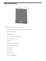
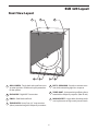
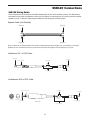
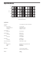
SUB120
R
E
F
E
R
E
N
C
E
SUBWOOFER
SAMSON
OWNERS MANUAL
®
Safety Instructions
Caution: To reduce the hazard of electrical
shock, do not remove cover or back.
No user serviceable parts inside. Please refer
all servicing to qualified personnel.
CAUTION
FOR CONTINUED PROTECTION AGAINST RISK
OF FIRE, REPLACE ONLY WITH SAME TYPE FUSE
ATTENTION
UTILISER UN FUSIBLE DE
RECHANGE DE MÊME TYPE
WARNING
DO NOT EXPOSE THIS EQUIPMENT
TO RAIN OR MOISTURE
AVIS
RISQUE DE CHOC ELECTRONIQUE
NE PAS OUVRIR
RISK OF ELECTRIC SHOCK
DO NOT OPEN
WARNING: To reduce the risk of fire or electric shock, do not expose this unit to rain or moisture.
The lightning flash with an arrowhead symbol within an equilateral triangle, is intended to alert the user to the
presence of uninsulated "dangerous voltage" within the products enclosure that may be of sufficient magnitude to
constitute a risk of electric shock to persons.
The exclamation point within an equilateral triangle is intended to alert the user to the presence of important operating and maintenance (servicing) instructions in the literature accompanying the product.
Important Safety Instructions
1. Please read all instructions before operating the unit.
2. Keep these instructions for future reference.
3. Please heed all safety warnings.
4. Follow manufacturers instructions.
5. Do not use this unit near water or moisture.
6. Clean only with a damp cloth.
7. Do not block any of the ventilation openings. Install in accordance with the manufacturers instructions.
8. Do not install near any heat sources such as radiators, heat registers, stoves, or other apparatus (including
amplifiers) that produce heat.
9. Do not defeat the safety purpose of the polarized or grounding-type plug. A polarized plug has two blades with
one wider than the other. A grounding type plug has two blades and a third grounding prong. The wide blade or
third prong is provided for your safety. When the provided plug does not fit your outlet, consult an electrician for
replacement of the obsolete outlet.
10. Protect the power cord from being walked on and pinched particularly at plugs, convenience receptacles and at
the point at which they exit from the unit.
11. Unplug this unit during lightning storms or when unused for long periods of time.
12. Refer all servicing to qualified personnel. Servicing is required when the unit has been damaged in any way,
such as power supply cord or plug damage, or if liquid has been spilled or objects have fallen into the unit, the
unit has been exposed to rain or moisture, does not operate normally, or has been dropped.
1
Table of Contents
Introduction
SUB120 Features
3
4
SUB120 Layout
Front View Layout
Rear Panel Layout
5
6
Setting Up the SUB120
Configuring Your Speaker system
7
7-8
Operating the SUB120
Connecting the Sub120
Using the SUB120 with the Samson DMS80 Monitor System
Mono Sub With Passive Satellites Using Speaker Inputs
Mono Sub With Passive Satellites Using Line Inputs
Mono Sub With Active Satellites
Stereo Sub With Passive Satellites
9-10
11
12
13
14
SUB120 Wiring Guide
15
Specifications
16
Copyright 2001, Samson Technologies Corp.
Printed March, 2001
Samson Technologies Corp.
575 Underhill Blvd.
P.O. Box 9031
Syosset, NY 11791-9031
Phone: 1-800-3-SAMSON (1-800-372-6766)
Fax: 516-364-3888
www.samsontech.com
2
Introduction
Thank you for purchasing the Samson SUB 120 Reference Subwoofer. The Samson SUB
120 is a self powered 120 Watt subwoofer featuring a 10”, 25mm excursion transducer with
Butyl surround. The SUB 120 is a perfect add-on to your Samson DMS80 monitor system,
or for any near field monitor system where extended low end is desired.
In these pages, you’ll find a detailed description of the features of the SUB120 subwoofer, as
well as a guided tour through its control panel, step-by-step instructions for its setup and
use, and full specifications. You’ll also find a warranty card enclosed—please don’t forget to
fill it out and mail it in so that you can receive online technical support and so we can send
you updated information about these and other Samson products in the future.
With proper care and adequate air circulation, your SUB120 will operate trouble free for
many years. We recommend you record your serial number in the space provided below for
future reference.
Serial number:
Date of purchase:
Should your unit ever require servicing, a Return Authorization number (RA) must be
obtained before shipping your unit to Samson. Without this number, the unit will not be
accepted. Please call Samson at 1-800-3SAMSON (1-800-372-6766) for a Return
Authorization number prior to shipping your unit. Please retain the original packing materials
and if possible, return the unit in the original carton and packing materials.
3
SUB 120 Features
SAMSON
The Samson SUB 120. Here are some of its main features:
•
Heavy-duty, 10” Long Excursion (25mm) Transducer With Butyl Surround
•
120 Watt Power Amplifier
•
Tuned Port Enclosure
•
High Pass Outputs for Satellite Speakers
•
Variable Crossover 40 - 180 Hz
•
Phase Switch
•
Line Inputs and Outputs on RCA jacks
•
Speaker Terminal Inputs and Outputs
•
Auto Sleep Switch
•
Volume Control
•
Black Satin Finish
•
Three-year extended warranty
4
SUB 120 Layout
Front View Layout
2
1
4
3
5
1
GRILL SCREEN - Tough cloth and wood frame construction provides durable and stylish protection
for the speaker.
2
ENCLOSURE - Rigid MDF Construction.
3
FINISH - Sleek black oak finish.
4
TRANSDUCER - Heavy Duty 10,” long excursion
(25mm) extended range low frequency transducer .
6
5
7
5
BUTYL SURROUND - Provides maximum excursion while maintaining tight bass response.
6
TUNED PORT - Quiet port design offering linear
extended low frequency response. (Rear of unit.)
7
NON-SKID FEET - Large rubber feet keep enclosure in place even at high sound pressure levels.
SUB 120 Layout
Rear Panel Layout
1
3
2
6
5
4
7
9
8
FROM EXTERNAL AMPLIFIER
SPEAKER OUTPUT
POWER
5
AUTO ON
OFF
ON
70
0°
PREAMP LEVEL
INPUT
OUTPUT
180°
PROTECT
R
R
L
L
+ R
-
-
L
+
+ R
-
-
L
+
PHASE
0
10
VOLUME
40
180
SWEEP Hz
TO PASSIVE SATELLITE SPEAKERS
SUB120 120 WATT 10" SUBWOOFER
SAMSON
DESIGNED AND ENGINEERED IN THE
UNITED STATES BY SAMSON TECHNOLOGIES
CAUTION
CAUTION: TO REDUCE THE RISK OF FIRE OR ELECTRIC SHOCK
DO NOT REMOVE BOTTOM COVER
NON SERVICEABLE PARTS INSIDE
DO NOT EXPOSE THIS EQUIPMENT TO RAIN OR MOISTURE
REFER SERVICING TO QUALIFIED PERSONNEL
RISK OF ELECTRICAL SHOCK
DO NOT OPEN
RISQUE DE SHOCK ELECTRIQUE
NE PAS OUVRIR
SERIAL NUMBER :
FUSE
115VAC
230VAC
NOT SUITABLE FOR IN-WALL MOUNTING
www.samsontech.com
10
1
2
3
4
5
6
MADE IN CHINA
12
11
7
VOLUME - Controls the amount of output
level.
SWEEP HZ - Adjusts the low frequency end
range of the High-Pass outputs.
POWER/PROTECT LED - Indicates power is on
and if amplifier is in Protect mode.
AUTO SLEEP SWITCH - When activated, Sleep
Mode conserves power by automatically
turning unit into standby mode after 10 minutes of non-use.
PHASE SWITCH - Allows for 180 degrees outof-phase operation.
PREAMP LEVEL INPUT - Accepts Line Level
input signals from mixer .
8
9
10
11
12
13
.
6
13
PREAMP LEVEL OUTPUT - Sends Low Level
Output signal.
SPEAKER LEVEL INPUT- Accepts full range
signals from power amplifier.
SPEAKER LEVEL OUTPUT- Sends full range
signals to satellite speakers.
HEAT SINK - Provides cooling of internal
power amplifier.
SERIAL NUMBER - Unit serial number is
located here.
FUSE - User accessible fuse.
POWER CORD - Heavy duty power cord.
Setting up the SUB120
CONFIGURING YOUR SPEAKER SYSTEM
Before you start plugging in cables, you should take a minute and decide how you want to interface your new
subwoofer. There are several ways you can interface the SUB120 and two specific categories should be considered. First, Stereo vs Mono operation, and second, whether High (powered) or Low (line) level inputs and outputs
will be used.
Common Sub Operation
In most cases, a common sub ( mono) bass operation
is desired. This is true for several reasons, but mostly
because low frequencies produced by a subwoofer
tend to be non-directional. Since low frequency waves
take so much space to actually develop, you can’t tell if
the sub-bass is coming from the left or right side.
Unless of course you’re in a very large room. Because
of this phenomena, just about all sub-bass material is
mixed in mono.
SAMSON
SAMSON
Stereo Sub Operation
SAMSON
Two SUB120’s can be used in stereo in larger control
rooms for increased low end. In addition, two
SUB120’s can be used in stereo, even in smaller control rooms, to help minimize standing waves. By using
two subwoofers at lower power, you can achieve a
more even response throughout the room.
SAMSON
SAMSON
Placing the SUB120
Because the low frequencies reproduced by the
SUB120 are non-directional, you can position the unit
almost anywhere. It is however, a good idea to keep
the SUB 120 away from corners. Ideally the SUB120
should be positioned in the middle, and up close to, the
wall you are facing in the mixing position.
SAMSON
SAMSON
Operating the SUB120
SUB120 Control Panel
The SUB120’s control panel provides the connections and user interface to the SUB120’s internal electronic
crossover and power amplifier section. The internal amplifier is a 120 Watt power amplifier capable of producing
incredible bass output. The SUB120 employs an electronic crossover that adjusts the high frequency cutoff point
for the subwoofer, and also, a high- pass output for your satellite speakers. You will achieve a tremendous benefit in sound quality by running your satellites speakers from the SUB120’s High-Pass outputs. The reason for this
is that when your satellite speaker receives the filtered output from the SUB120, it will no longer be looking at the
frequency below the crossover point. Let’s say your satellite speaker has a natural frequency roll-off at 70 Hz,
and you are sending full range signal (as low as 20Hz) to the satellite amplifier and speaker. Even though the
speaker can only reproduce 70Hz and up, the amplifier is still outputting 20-70Hz, which is wasted power and ultimately turns into heat. By using the SUB120’s High-Pass output, the satellite amplifier and speaker never see
the frequencies lower than what’s set by the Sweep frequency. This means you’ll have more power dedicated to
7
Operating the SUB120
SUB120 Control Panel - Continued
to the frequencies you want the satellites to reproduce, resulting in a much cleaner sound with more headroom.
1 Volume Control
The volume control is used to adjust the amount of level
to the SUB120 subwoofer. In addition, the volume
control will also control the output level of the high-pass
outputs. Therefore, if you are using the SUB120 without
using the high-pass outputs (for example, when the
SUB120 is connected to an external crossover) the
volume control adjusts the low frequency output of the
SUB120. If you are using the SUB120’s internal
electronic crossover to run satellite speakers, then the
volume control will adjust the overall system level.
3
POWER
5
AUTO ON
OFF
ON
70
0°
5
180°
PROTECT
1
0
10
VOLUME
2
4
40
180
PREAMP LEVEL
INPUT
OUTPUT
6
R
R
L
L
FROM EXTERNAL AM
SPEAKER OUT
+ R
-
+ R
-
PHASE
SWEEP Hz
TO PASSIVE SATELLITE
SUB120 120 WATT 10" SUBWOOFER
2 Sweep Hz
The Sweep Hz control selects the upper range cutoff frequency of the SUB120’s internal electronic crossover.
The SUB120’s crossover provides a 12dB per octave Linkwitz Riley filter curve. The Sweep adjusts the highest
frequency that the SUB120 will reproduce, and at the same time, the high-pass outputs track the selected
crossover frequency as the lower limit frequency to the satellite speakers.
3 Power/Protect LED
The POWER/PROTECT LED is a dual color LED which has three states; OFF, GREEN AND RED. The following
chart shows the POWER/PROTECT LED and the different operating conditions it represents.
AUTO ON SWITCH
LED - OFF
LED - GREEN
LED - RED
ON
AUTO
OFF
Not Applicable
SLEEP
SUB120 - OFF
SUB120 - ON
SUB120 - ON
Not Applicable
PROTECT
PROTECT
Not Applicable
If the SUB120 receives a clipped signal for a long duration of time the unit will shut down and enter PROTECT
mode. When the SUB120 is in Protect, you will see the POWER /PROTECT LED is lit up in red. If this happens
simply turn the unit off, wait a minute and then re-power up the unit. The LED should return to a green color again
indicating normal operation . At this point, readjust the level you’re sending to the SUB120 so that the signal is
not clipped and the unit will operate properly.
4 Auto On Switch
The AUTO ON switch is used to select the SUB120’s power operating mode. When the switch is set to OFF the
unit is not operational. When the AUTO ON switch is set to the ON position, the unit is always on. To engage
the SUB120’s SLEEP function, slide the AUTO ON switch to the AUTO position. In this mode, the SUB120 enters
a stand-by, or "SLEEP" condition after no input signal is sensed for a period of approximately 10 minutes. The
SUB120 will return to the normal operating mode as soon as it senses a signal present at the inputs.
5 Phase Switch
The SUB120 can be switched for inverted phase operation by setting the PHASE SWITCH to the 180° (degree)
position. Experiment with this switch to provide the best blend between the subwoofer and satellite speakers.
6 The Ins and The Outs
The SUB120 features both line level and speaker level inputs and outputs so that connection with passive or
active satellites is easy. The PREAMP LEVEL INPUTS simply pass the line level signal through to the PREAMP
LEVEL OUTPUTS. You can use the line inputs and outputs to interface the SUB120 with active monitors. The
SPEAKER LEVEL INPUTS can be connected from the speaker outputs of a power amplifier, and then the signal
is sent from the SPEAKER OUTPUTS, which are high-passed, to passive satellite speakers. The following sections of this manual detail the set-ups for many typical configurations with both passive and active monitors. In
addition, there is a detailed cable wiring diagram on page 15.
8
-
Connecting the SUB120
USING THE SUB120 WITH THE SAMSON DMS80 MONITOR SYSTEM
Using The DMS80’s SUB OUT
The SUB120 is a great add on to your DMS monitor system providing extended low frequency output. There are
several ways you can interface your new subwoofer to the DMS80, including using the DMS80’s mono SUB
OUT, or by using the DMS 80’s LINE OUTs. The following examples outline the connections and operation for
the SUB120 working with the DMS80 system.
–
+
INPUT
+
–
–
SPEAKER OUTPUTS
LEFT+
LEFT-
LINE IN
LEFT
RIGHT
SPEAKER IMPEDANCE 4-8
RIGHTRIGHT+
AUX IN
LEFT
RIGHT
LINE OUT
LEFT
RIGHT
+
INPUT
SUB OUT
MONO
RISK OF ELECTRIC SHOCK
DO NOT OPEN
WARNING
DO NOT EXPOSE THIS EQUIPMENT
TO RAIN OR MOISTURE
AVIS
RISQUE DE CHOC ELECTRONIQUE
NE PAS OUVRIR
CAUTION
FOR CONTINUED PROTECTION AGAINST RISK
OF FIRE, REPLACE ONLY WITH SAME TYPE FUSE
ATTENTION
UTILISER UN FUSIBLE DE
RECHANGE DE MÊME TYPE
SAMSON
SERIAL
NUMBER
DESKTOP MONITOR SYSTEM STEREO 40W X2 MODEL:DA80
MADE IN CHINA
–
+
FROM EXTERNAL AMPLIFIER
SPEAKER OUTPUT
POWER
5
AUTO ON
OFF
ON
70
0°
PREAMP LEVEL
INPUT
OUTPUT
180°
PEAK
R
R
L
L
+ R
-
-
L
+
+ R
-
-
L
+
PHASE
0
10
VOLUME
40
180
SWEEP Hz
TO PASSIVE SATELLITE SPEAKERS
SUB120 120 WATT 10" SUBWOOFER
•
Make the connections between your mixer and your DMS80 monitor system as described in the DMS80’s
users manual and make sure that you turn your mixer all the way down.
*
Connect the SUBWOOFER OUTPUT located on the rear panel of the DMS80 to the RIGHT PREAMP
INPUT on the SUB120.
•
Set the SUB120’s Volume control to about 6, and since the DMS80’s SUBWOOFER OUTPUT is Highpassed at 100 Hz, set the SWEEP control to 180Hz.
•
Now run some audio, like music on a CD, through your mixer and raise the output to the DMS80 monitor
system to a comfortable listening level.
•
Now slowly raise the SUBWOOFER LEVEL control located on the DMS80 front control panel and adjust
the low frequency output to your taste. You can experiment with the balance between the SUB120 and
the DMS satellite speakers by adjusting the SUBWOOFER LEVEL control. Once you find the balance
you like, the SUB120 will track the satellites when you raise or lower your mixer’s output.
9
Connecting the SUB120
USING THE SUB120 WITH THE SAMSON DMS80 MONITOR SYSTEM
Using The DMS80’s LINE OUTs
The SUB120 can be connected to the DMS80’s by using the LINE OUTS located on the DMS80’s rear panel.
When using the DMS80’s LINE outputs you will utilize the SUB120 internal electronic crossover, which will allow
you to experiment and fine-tune your monitor system. Follow the diagram and instructions below to interface your
new subwoofer.
–
+
INPUT
+
–
–
SPEAKER OUTPUTS
LEFT+
LEFT-
LINE IN
LEFT
RIGHT
SPEAKER IMPEDANCE 4-8
RIGHTRIGHT+
AUX IN
LEFT
RIGHT
LINE OUT
LEFT
RIGHT
+
INPUT
SUB OUT
MONO
RISK OF ELECTRIC SHOCK
DO NOT OPEN
WARNING
DO NOT EXPOSE THIS EQUIPMENT
TO RAIN OR MOISTURE
AVIS
RISQUE DE CHOC ELECTRONIQUE
NE PAS OUVRIR
CAUTION
FOR CONTINUED PROTECTION AGAINST RISK
OF FIRE, REPLACE ONLY WITH SAME TYPE FUSE
ATTENTION
UTILISER UN FUSIBLE DE
RECHANGE DE MÊME TYPE
SAMSON
SERIAL
NUMBER
DESKTOP MONITOR SYSTEM STEREO 40W X2 MODEL:DA80
MADE IN CHINA
–
+
FROM EXTERNAL AMPLIFIER
SPEAKER OUTPUT
POWER
5
AUTO ON
OFF
ON
70
0°
PREAMP LEVEL
INPUT
OUTPUT
180°
PEAK
R
R
L
L
+ R
-
-
L
+
+ R
-
-
L
+
PHASE
0
10
VOLUME
40
180
SWEEP Hz
TO PASSIVE SATELLITE SPEAKERS
SUB120 120 WATT 10" SUBWOOFER
•
Make the connections between your mixer and your DMS80 monitor system as described in the DMS80’s
users manual and make sure that you turn your mixer all the way down.
*
Connect the RIGHT and LEFT LINE OUTPUTS located on the rear panel of the DMS80 to the RIGHT
and LEFT PREAMP INPUTS on the SUB120.
•
Turn the SUB120’s Volume all the way off, and set the SWEEP control to 100Hz.
•
Now run some audio, like music on a CD, through your mixer and raise the output to the DMS80 monitor
system to a comfortable listening level.
•
Now, slowly raise the SUB120’s LEVEL control and adjust the low frequency output to your taste. You
can experiment by listening to the difference when adjusting the crossover point with the SWEEP control.
Also, listen as you adjust the balance between the SUB120 and the DMS satellite speakers by changing
the SUB120’s LEVEL control. Once you find the balance you like, the SUB120 will track the satellites
when you raise or lower your mixer’s output.
10
Connecting the SUB120
Mono Sub With Passive Satellites Using Speaker Inputs
The SUB120 is a perfect addition to any near-field monitoring system where enhanced low-end is desired. Below
is a typical system set using the SUB120 with a mixer, amplifier and a pair of passive satellite speakers. In this
mode, the signal sent to the satellite is high-passed at 100Hz. The SUB120’s input and outputs utilize industry
standard speaker connectors. Follow the steps below the diagram to set up your system.
–
+
–
INPUT
+
INPUT
SAMSON
AMPLIFIER
FROM MIXER
CAUTION
TO PREVENT SHOCK, DO NOT OPEN. NO USER SERVICEABEL PARTS INSIDE. REFER SERVICING TO
QUALIFIED SERVICE PERSONNEL. TO PREVENT FIRE OR SHOCK HAZARD. DO NOT EXPOSE TO
RAIN OR MOISTURE.
OUTPUT
PUSH TO RESET
20A / 250V
CHANNEL 1
CHANNEL 2
CAUTION ; REPLACE WITH THE SAME TYPE FUSE AS INDICATED.
UTILISER UN FUSIBLE DE RECHANGE DE MEME TYPE.
INPUTS
MINIMUM LOAD IMPEDANCE
STEREO +
(4 /CHANNEL)
BRIDGED MONO
(8 )
~AC INPUT
115V / 60Hz, 800W
+
-
TIP RING SLEEVE
TIP RING SLEEVE
TIP
+
RING
SLEEVE GND
TIP
+
RING
SLEEVE GND
CHANNEL 2
CHANNEL 1
+
MODE SELECTOR
POWER
RATING
115V - 60Hz 800W
SERIAL NUMBER
AVIS ; RISQUE DE CHOC ELECTRIQUE NE PAS OUVRIR
INPUT
DO NOT EXPOSE THIS EQUIPMENT TO RAIN OR MOISTURE.
CAUTION
(10K
RISK OF ELECTRIC SHOCK
DO NOT OPEN.
BRIDGED
/ 0dBu)
INPUT
STEREO
(10K
/ 0dBu)
www.samsontech.com
MADE IN KOREA
FROM EXTERNAL AMPLIFIER
SPEAKER OUTPUT
POWER
5
AUTO ON
OFF
ON
70
0°
PREAMP LEVEL
INPUT
OUTPUT
180°
PEAK
R
R
L
L
+ R
-
-
L
+
+ R
-
-
L
+
PHASE
0
10
VOLUME
40
180
SWEEP Hz
TO PASSIVE SATELLITE SPEAKERS
SUB120 120 WATT 10" SUBWOOFER
•
Lower your mixer’s master outputs to all the way off.
•
Connect the mixer’s left output to the left input of your power amp and the mixer’s right output to the right
input of your power amp. Now, using standard speaker cable, connect the power amp’s left speaker output to the SUB120’s LEFT SPEAKER INPUT and the power amp’s right speaker output to the SUB120’s
RIGHT SPEAKER INPUT. To complete the connections, run a cable from the SUB120’s LEFT SPEAKER OUTPUT to the left satellite and from the RIGHT SPEAKER OUTPUT to the right satellite speaker.
•
Now adjust the SWEEP control to the desired frequency. Consult your studio monitors owner’s manual
for a recommended crossover point. You can also use your ears by adjusting the SWEEP control to the
frequency that sounds good to you. A good place to start is about 70 Hz.
•
Now set the level of your power amp up to the normal operating level. Run an audio signal (like some
music from a CD) through your mixer and raise the level to a comfortable listening level. Now slowly
raise the SUB120 Volume control and listen to the low frequency output. Adjust the SUB120 to the level
of low frequency output that you like. Now, when you raise and lower your mixer’s output, the SUB120
and satellites will track at the same relative volume.
11
Connecting the SUB120
Mono Sub With Passive Satellites Using Line Inputs
The SUB120 can be operated using line level inputs and outputs. When using the SUB120 at line level, the full
range signal is maintained at the outputs. Below is a typical system set up using the SUB120 with a mixer, stereo
power amp and a pair of passive satellite loudspeakers. The SUB120’s inputs and outputs utilize industry standard RCA connectors. For a detailed wiring diagram, see the section SUB120 Connections on page 17. Follow
the steps below the diagram to set up your system.
–
+
–
INPUT
+
INPUT
SAMSON
AMPLIFIER
CAUTION
TO PREVENT SHOCK, DO NOT OPEN. NO USER SERVICEABEL PARTS INSIDE. REFER SERVICING TO
QUALIFIED SERVICE PERSONNEL. TO PREVENT FIRE OR SHOCK HAZARD. DO NOT EXPOSE TO
RAIN OR MOISTURE.
OUTPUT
PUSH TO RESET
20A / 250V
CHANNEL 1
CHANNEL 2
CAUTION ; REPLACE WITH THE SAME TYPE FUSE AS INDICATED.
UTILISER UN FUSIBLE DE RECHANGE DE MEME TYPE.
INPUTS
MINIMUM LOAD IMPEDANCE
STEREO +
(4Ω/CHANNEL)
BRIDGED MONO
(8Ω)
~AC INPUT
115V / 60Hz, 800W
+
-
CHANNEL 2
TIP RING SLEEVE
TIP RING SLEEVE
TIP
+
RING
SLEEVE GND
TIP
+
RING
SLEEVE GND
CHANNEL 1
+
MODE SELECTOR
POWER
RATING
115V - 60Hz 800W
SERIAL NUMBER
AVIS ; RISQUE DE CHOC ELECTRIQUE NE PAS OUVRIR
DO NOT EXPOSE THIS EQUIPMENT TO RAIN OR MOISTURE.
CAUTION
INPUT
BRIDGED
(10KΩ / 0dBu)
RISK OF ELECTRIC SHOCK
DO NOT OPEN.
INPUT
STEREO
(10KΩ / 0dBu)
www.samsontech.com
MADE IN KOREA
FROM MIXER
FROM EXTERNAL AMPLIFIER
SPEAKER OUTPUT
POWER
5
AUTO ON
OFF
ON
70
0°
PREAMP LEVEL
INPUT
OUTPUT
180°
PEAK
R
R
L
L
+ R
-
-
L
+
+ R
-
-
L
+
PHASE
0
10
VOLUME
40
180
SWEEP Hz
TO PASSIVE SATELLITE SPEAKERS
SUB120 120 WATT 10" SUBWOOFER
•
Lower your mixer’s master outputs to all the way off.
•
Connect the mixer’s left output to the SUB120’s LEFT PREAMP LEVEL INPUT and the mixer’s right output to the SUB120’s RIGHT PREAMP LEVEL INPUT. Now connect the SUB120’s LEFT PREAMP
LEVEL OUTPUT to the left side input of the power amp, and the SUB120’s RIGHT PREAMP LEVEL
OUTPUT to the right side input of the power amp. Connect a speaker wire from the left output of your
power amp to your left satellite, and then, connect a speaker wire from the right output of your power
amp to your right satellite.
•
Now adjust the SWEEP control to the desired frequency. Consult your studio monitors owner’s manual
for a recommended crossover point. You can also use your ears by adjusting the SWEEP control to the
frequency that sounds good to you. A good place to start is about 70 Hz.
•
Now set the level of your power amp up to the normal operating level. Run an audio signal (like some
music from a CD) through your mixer and raise the level to a comfortable listening level. Now slowly
raise the SUB120 volume control and listen to the low frequency output. Adjust the SUB120 to the level
of low frequency output that you like. Now, when you raise and lower your mixer’s output, the SUB120
and satellites will track at the same relative volume.
12
Connecting the SUB120
Mono Sub With Active Satellites
If you have active studio monitors, installation is easy through the SUB120’s LINE LEVEL inputs and outputs.
Below is a typical system set up using the SUB120 with a mixer and a pair of active satellite speakers. The
SUB120’s input and outputs utilize industry standard RCA connectors. For a detailed wiring diagram, see the
section SUB120 Connections on page 15. Follow the steps below the diagram to set up your system.
LINE INPUT
LINE INPUT
~AC INPUT
115V / 60Hz, 800W
~AC INPUT
115V / 60Hz, 800W
FROM MIXER
FROM EXTERNAL AMPLIFIER
SPEAKER OUTPUT
POWER
5
AUTO ON
OFF
ON
70
0°
PREAMP LEVEL
INPUT
OUTPUT
180°
PEAK
R
R
L
L
+ R
-
-
L
+
+ R
-
-
L
+
PHASE
0
10
VOLUME
40
180
SWEEP Hz
TO PASSIVE SATELLITE SPEAKERS
SUB120 120 WATT 10" SUBWOOFER
•
Lower your mixer’s master outputs to all the way off.
•
Connect the mixer’s left output to the SUB120’s LEFT LINE INPUT and the mixer’s right output to the
SUB120’s RIGHT LINE INPUT. Now connect the SUB120’s LEFT LINE OUTPUT to the input of the left
powered satellite, and the SUB120’s RIGHT LINE OUTPUT to the input of the right powered satellite.
•
Now adjust the SWEEP control to the desired frequency. Consult your studio monitors owner’s manual
for a recommended crossover point. You can also use your ears by adjusting the SWEEP control to the
frequency that sounds good to you. A good place to start is about 70 Hz.
•
Now set the level of your power amp up to the normal operating level. Run an audio signal (like some
music from a CD) through your mixer and raise the level to a comfortable listening level. Now slowly
raise the SUB120 VOLUME control and listen to the low frequency output. Adjust the SUB120 to the level
of low frequency output that you like. Now, when you raise and lower your mixer’s output, the SUB120
and satellites will track at the same relative volume.
13
Connecting the SUB120
Stereo Sub With Passive Satellites
Two SUB120’s can be used with any pair of passive or active monitors. Below is a typical system set using two
SUB120’s with a mixer, stereo power amp and a pair of passive satellite loud speakers. The SUB120’s input and
outputs utilize industry standard RCA connectors. For a detailed wiring diagram, see the section SUB120
Connections on page 15. Follow the steps below the diagram to set up your system
–
–
+
+
INPUT
INPUT
SAMSON
AMPLIFIER
CAUTION
TO PREVENT SHOCK, DO NOT OPEN. NO USER SERVICEABEL PARTS INSIDE. REFER SERVICING TO
QUALIFIED SERVICE PERSONNEL. TO PREVENT FIRE OR SHOCK HAZARD. DO NOT EXPOSE TO
RAIN OR MOISTURE.
OUTPUT
PUSH TO RESET
20A / 250V
CHANNEL 1
CHANNEL 2
CAUTION ; REPLACE WITH THE SAME TYPE FUSE AS INDICATED.
UTILISER UN FUSIBLE DE RECHANGE DE MEME TYPE.
INPUTS
MINIMUM LOAD IMPEDANCE
STEREO +
(4 /CHANNEL)
BRIDGED MONO
(8 )
~AC INPUT
115V / 60Hz, 800W
+
-
CHANNEL 2
TIP RING SLEEVE
TIP RING SLEEVE
TIP
+
RING
SLEEVE GND
TIP
+
RING
SLEEVE GND
CHANNEL 1
+
MODE SELECTOR
POWER
RATING
SERIAL NUMBER
115V - 60Hz 800W
AVIS ; RISQUE DE CHOC ELECTRIQUE NE PAS OUVRIR
DO NOT EXPOSE THIS EQUIPMENT TO RAIN OR MOISTURE.
CAUTION
INPUT
(10K
RISK OF ELECTRIC SHOCK
DO NOT OPEN.
/ 0dBu)
BRIDGED
STEREO
INPUT
(10K
/ 0dBu)
www.samsontech.com
FROM MIXER
FROM EXTERNAL AMPLIFIER
SPEAKER OUTPUT
POWER
5
AUTO ON
OFF
ON
70
0°
PREAMP LEVEL
INPUT
OUTPUT
180°
PEAK
R
+ R
-
-
L
FROM EXTERNAL AMPLIFIER
SPEAKER OUTPUT
+
POWER
5
AUTO ON
OFF
ON
70
10
VOLUME
40
180
SWEEP Hz
PREAMP LEVEL
INPUT
OUTPUT
180°
PEAK
R
PHASE
0
0°
R
R
L
L
+ R
-
-
L
+
+ R
-
-
L
+
PHASE
L
L
0
+ R
-
-
L
+
10
VOLUME
40
180
SWEEP Hz
•
Lower your mixer’s master outputs to all the way off.
•
Connect the mixer’s left output to the left side SUB120’s LEFT PREAMP INPUT and the mixer’s right
output to the right side SUB120’s RIGHT PREAMP LEVEL INPUT. Now connect the left SUB120’s LEFT
PREAMP OUTPUT to the left side input of the power amp, and the right SUB120’s RIGHT PREAMP
LEVEL OUTPUT to the right side input of the power amp. Connect a speaker wire from the left output of
your power amp to your left satellite, and then, connect a speaker wire from the right output of your
power amp to your right satellite.
•
Now adjust the SWEEP control to the desired frequency. Consult your studio monitors owner’s manual
for a recommended crossover point. You can also use your ears by adjusting the SWEEP control to the
frequency that sounds good to you. A good place to start is about 70 Hz.
•
Now set the level of your power amp up to the normal operating level. Run an audio signal (like some
music from a CD) through your mixer and raise the level to a comfortable listening level. Now slowly
raise the SUB120 Volume control and listen to the low frequency output. Adjust the SUB120 to the level
of low frequency output that you like. Now, when you raise and lower your mixer’s output, the SUB120
and satellites will track at the same relative volume.
14
SUB120 Connections
SUB120 Wiring Guide
There are several ways to interface the SUB120 depending on your exact monitoring set-up. The SUB120 features both Preamp Level and Speaker Level inputs and outputs, so connecting to any active or passive satellites
speakers is easy. Follow the cable diagrams below for connecting your monitor system.
Speaker Cable (Un-Shielded)
Positive
Positive
Negitive
Negitive
Note: Just about all un-shielded speaker wire will have a marking indicating the negative side. To avoid phase cancelation
problems, be sure to maintain the correct connection for the positive and negative sides throughout your system.
Unbalanced 1/4” to RCA Cable
Tip (signal)
Tip (signal)
Sleeve (ground)
Tip (signal)
Sleeve (ground)
Sleeve (ground)
Un-Balanced XLR to RCA Cable
Tip (signal)
Hot (2) Common (1)
1
2
3
End View
2
Tip (signal)
1
3
Cold (Pin 3)
(no connection)
Solder Points
Cold (3)
Sleeve (ground)
Male XLR
Sleeve (ground)
15
Specifications
+40
+20
d
b
u
0
-20
-40
20
50
100
200
500
1k
2k
5k
Hz
Sub 120 Frequency Chart
Specifications
Transducer:
10", Long Excursion ( 25mm ) Transducer
Amplifier
Power Rating:
Frequency response
Sensitivity:
120 Watts RMS
30Hz- 300Hz+/-3 dB
94dB SPL @ 1 W/1m
Speaker Input
Connector:
Push Terminal
Speaker Output
Connector:
High-passed.
Push Terminal
Line Input
Connector:
Un-Balanced
RCA - FEMALE
Line Output
Connector:
Un-Balanced
RCA - FEMALE
Crossover Frequency:
Variable 40Hz – 180Hz
Enclosure
Construction:
Finish:
Feet:
MDF (Medium Density Fiberboard)
Black Vinyl
Large Rubber
Dimensions:
17″ (h) x 14 (w) x 16.25 (d)
432 mm (h) x 356 (w) x 413 (d)
Weight:
39 lbs.
17.75 kg.
16
1k
20k
Samson Technologies Corp.
575 Underhill Blvd.
P.O. Box 9031
Syosset, NY 11791-9031
Phone: 1-800-3-SAMSON (1-800-372-6766)
Fax: 516-364-3888
www.samsontech.com