1
Operator's
Manual
M
2-Cycle
WEEDWACKER® TRIMMER
Model No. 316.791191
INCREDI.PULL_
TM
UNBELIEVABLE
STARTING
EA S E
TM
• SAFETY
ASSEMBLY
OPERATION
MAINTENANCE
PARTS LIST
ESPANOL, R 11
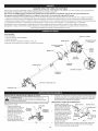
CAUTION:
Before using this
product, read this manual
and follow all safety rules
and operating
instructions.
Sears Brands Management
Corporation,
Visit our website:
769-06344
P01
Hoffman
Estates, IL 60179 U.S.A.
www.craftsrnan.corn
6/11
CALiFORNiA
PROPOSiTiON
65 WARNING
The purpose of safety symbols is to attract your attention to possible dangers.
The safety symbols, and their explanations, deserve your careful attention and
understanding. The safety warnings do not by themselves eliminate any danger.
The instructions or warnings they give are not substitutes for proper accident
prevention measures.
THE ENGINE EXHAUST FROM THIS PRODUCT CONTAINS CHEMICALS
KNOWN TO THE STATE OF CALHFORNIA TO CAUSE CANCER, BIRTH
DEFECTS OR OTHER REPRODUCTIVE HARM.
SYMBOL
Attention is ALERT:
required inIndicates
order to avoid
personal
injury.
SAFETY
danger,serious
warning
or caution.
May be used in conjunction with other symbols or pictographs.
TABLE OF CONTENTS
Safety Rules .................................................
Warranty ....................................................
Know Your Unit ...............................................
2
4
4
Assembly Instructions ..........................................
Oil and Fuel Information ........................................
4
5
Starting/Stopping
Instructions
...................................
Operating Instructions
.........................................
Maintenance and Repair Instructions ..............................
Cleaning and Storage ..........................................
Troubleshooting Chart .........................................
Specifications
...............................................
Parts List ...................................................
Service Numbers .....................................
SPARK ARRESTOR
6
6
7
8
9
10
22
Back Cover
injury
to yourself
or to to
others.
thewill
safety
precautions
DANGER:
Failure
obey Always
a safety follow
warning
result
in serious
to reduce the risk of fire, electric shock and personal injury.
injury to yourself Failure
and others.
Always
follow
the safety
precautions
WARNING:
to obey
a safety
warning
can result
in
to reduce the risk of fire, electric shock and personal injury.
_IL
NOTE:
NOTE
NOTE: For users on U.S. Forest Land and in the states of California, Maine,
Oregon and Washington.
All U.S. Forest Land and the state of California
(Public Resources Codes 4442 and 4443), Oregon and Washington require, by
law that certain internal combustion engines operated on forest brush and/or
grass-covered areas be equipped with a spark arrestor, maintained in effective
working order, or the engine be constructed, equipped and maintained for the
prevention of fire. Check with your state or local authorities for regulations
pertaining to these requirements. Failure to follow these requirements could
subject you to liability or a fine. This unit is factory equipped with a spark
arrestor. If it requires replacement, ask your LOCAL SERVICE DEALER to install
the Accessory Part #753=06182 Muffler Assembly
• iMPORTANT
READ ALL iNSTRUCTiONS
vital to the operation or
All information, illustrations, and specifications in this manual are based on the
latest product information available at the time of printing. We reserve the right
to make changes at any time without notice.
SAFETY iNSTRUCTiONS
Squeeze the throttle control and check that it returns automatically to the
idle position. Make all adjustments or repairs before using the unit.
Always stop the unit when operation
location to another.
carefully. Be familiar with the controls and proper
Do not force the unit. It will do the job better and with less likelihood of
injury at a rate for which it was designed.
Do not overreach or use from unstable surfaces such as ladders, trees,
steep slopes, rooftops, etc. Always keep proper footing and balance.
Do not operate the unit faster than the speed needed to do the job. Do
not run the unit at high speed when not in use.
If the unit strikes or becomes entangled with a foreign object, stop the
unit immediately and check for damage. Do not operate before repairing
damage. Do not operate the unit with loose or damaged parts.
• Do not operate this unit when tired, ill or under the influence of alcohol,
drugs or medication.
• Children and teens under the age of 15 must not use the unit, except
teens guided by an adult.
purpose.
Use the unit only in daylight or good artificial light.
Wear safety glasses or goggles that meet ANSI Z87.1 standards and are
marked as such. Wear ear/hearing protection when operating this unit.
Wear a face or dust mask if the operation is dusty.
Keep unit clean of vegetation and other materials that may clog, gum or
bind moving parts, which may cause serious personal injury and or
damage to the unit.
Wear heavy long pants, boots, gloves and a long sleeve shirt. Do not
wear loose clothing, jewelry, short pants, sandals or go barefoot. Secure
hair above shoulder level.
Keep hands, face, and feet away from all moving parts. Do not touch or
try to stop any moving parts while they are in motion.
Inspect the unit before use. Replace damaged parts. Make sure all
fasteners are in place and secure. Replace parts that are cracked,
chipped or damaged in any way. Do not operate the unit with loose or
damaged parts.
Allow the unit to cool before storing or transporting.
unit while transporting.
• Clear the area of children, bystanders and pets; keep them outside a 50foot (15 m) radius, at a minimum. Even then, they are still at risk from
thrown objects. Encourage bystanders to wear eye protection. If
approached, stop the unit immediately.
• Carefully inspect the area before starting the unit. Remove all debris such
as rocks, broken glass, nails, wire, string and other objects which may be
thrown or become entangled in the unit.
Be sure to secure the
Never douse or squirt the unit with water or any other liquid. Keep
handles dry, clean and free from debris. Clean after each use, see
Cleaning and Storage instructions.
must be installed properly before
Use only manufacturers recommended replacement parts or accessories
for this unit. Use of any replacement parts or accessories purchased
elsewhere may be hazardous, and will void the warranty.
Be aware of risk of injury to the head, hands and feet.
is delayed or when walking from one
Always hold the unit with both hands when operating. Keep a firm grip on
both handles or grips.
• Keep these instructions. Refer to them often and use them to instruct
other users. If loaning this unit to others, also loan them these
instructions.
• All guards and safety attachments
operating the unit.
Advises of information or instructions
maintenance of the equipment.
This Unit Can Use a Plug-in Power Start or Power Bit Start
Optional Accessory!
Please refer to the Plug-In Power Start or Power Bit Start
operator's manual for proper use of these features. (Items may be
Sold Separately! Please refer to page 8 of this manual for more
information about purchasing these accessories.)
Read the Operator's
Manual
and follow
all warnings
and safety
instructions. Failure to do so can result in serious injury to the operator
and/or bystanders.
FOR QUESTIONS, CALL 1 =800=4=MY=HOME®
BEFORE OPERATING
Use the right tool. Only use this tool for its intended
property
damage
or personal
to warning
yourself or
others.in
CAUTION:
Failure
to obey injury
a safety
mayto result
Always follow the safety precautions to reduce the risk of fire,
electric shock and personal injury.
NOTE=
GENERAL SAFETY
• Read the instructions
use of the unit.
MEANING
Store the unit in a dry place, secured or at a height to prevent
unauthorized use or damage. Keep out of the reach of children.
OIL AND FUEL SAFETY
[_
explode
if ignited.
Take the
following
precautions:
WARNING:
Gasoline
is highly
flammable
and its vapors can
Store fuel only in containers
storage of such materials.
specifically
designed and approved for the
• Always stop the engine and allow it to cool before filling the fuel tank.
Never remove the fuel tank cap or add fuel when the engine is hot. Never
operate the unit without the fuel cap securely in place.
* Always mix or add fuel in a clean, well-ventilated
are no sparks or flames. Do not smoke.
outdoor
area where there
* Never operate the unit without the fuel cap securely nq place.
* Avoid creating a source of @qitlon for spilled fuel. Wipe up any spilled fuel
from the unit immediately before starting the unit. Move the unit at least
30 feet (9.1 m) from the fuehng source and site before starting the unit. Do
not smoke.
* Never start or run the unit reside a closed room or buildnqg. Breathing
exhaust fumes can be fatal. Operate this unit only in a well-ventilated
outdoor area.
* Check the unit for fuel leaks.
* Do not touch the engine, gear housing or muffler. These parts get
extremely hot from operahon, even after the umt is turned off.
* Turn the engine to off and disconnect
repar.
TRIMMER
the spark plug for maintenance
or
SAFETY
• The trimmer attachment shield must always be nqplace while operating
the unit. Do not operate unit without both trimming hnes extended, and
the proper hne installed. Do not extend the trimming hne beyond the
length of the shield.
• Adjust the D-handle that provides the best possible grip.
* Loosen the fuel tank cap slowly to relieve any pressure in the tank.
• Be sure the trimmer attachment
starting the unit.
* Never store the unit with fuel in the tank, reside a bLaldmg where fumes
may reach an open flame (pilot hghts, etc.) or sparks (switches, electrical
motors, etc.).
* To reduce fire hazard, replace a faulty muffler and spark arrestor. Keep the
engine and muffler free from grass, leaves, excesswe grease or carbon
build up.
• Use only 0.095 in (2.41 mm) replacement hne. Never use metal-reinforced
hne, wire, chain or rope. These can break off and become dangerous
projectiles.
• Keep unit clean of vegetahon and other materials. They may become
lodged between the trimmer attachment and shield.
* Avoid accidental starting. Be nqthe starting poslhon whenever pulhng the
starter rope. The operator and unit must be m a stable poslhon while
starting.
is not in contact with anything before
• Keep hands, face, and feet away from all mowng parts. Do not touch or
try to stop the trimmer attachment when it rotates.
SAVE THESE INSTRUCTIONS
_,SAFETY & INTERNATIONAL SYMBOLS _,
This operator's manual describes safety and mternahonal symbols and plctographs that may appear on this product. Read the operator's manual for
complete
SYMBOL
safety, assembly, operahng and maintenance and repair mformahon.
MEANING
SAFETY ALERT SYMBOL
SYMBOL
Inducates danger, warning or cauhon. May be used un
conjunction with other symbols or puctographs.
@
READ OPERATOR'S
MANUAL
WARNING:
Read the operator's manual(s) and folow air
warnings and safety unstructuons. Failure to do so can result
unsenous injury to the operator and/or bystanders.
WEAR EYE AND HEARING
PROTECTION
WARNING:
Thrown objects and loud no=se can cause
severe eye injury and heanng loss. Wear eye protecbon
meebng ANSI Z87.1-1989 standards and ear protection when
operating this unit. Use a furl face shield when needed.
UNLEADED
FUEL
Aiways use clean, fresh unleaded fuel
MEANING
• THROWN OBJECTS AND ROTATING CUTTER CAN
CAUSE SEVERE iNJURY
WARNING:
Small objects can be propeibd at high speed,
causing mnjury.Keep away from the rotating rotor.
A
• KEEP BYSTANDERS
AWAY
WARNING:
Keep all bystanders, especuaHy chddren and
pets, at least 50 feet (15 m.) from the operating area.
HOT SURFACE
WARNING:
Do not touch any metal engine components.
The engine gets extremely hot from operatuon and may cause
severe burns. Allow the unit to completely cool prior to any
maintenance or servicing.
OiL
Refer to operator's
manual for the proper type of oil.
• PRIMER BULB
DO NOT USE E85 FUEL iN THiS UNiT
Push primer bulb, fully and slowly, 10 times.
WARNING:
It has been proven that fuel containing greater
than 10% ethanol wull hkeiy damage this engine and void the
warranty.
|
O
ON/OFF STOP CONTROL
ON / START / RUN
ON/OFF
STOP CONTROL
OFF or STOP
• SHARP BLADE
WARNING:
Sharp blade on trimmer attachment shield. To
prevent serious injury, do not touch the Ime cutting blade.
CRAFTSMAN
2 YEAR
FULL
WARRANTY
FOR 2 YEARS from the date of purchase, this product is warranted against any defects in material or workmanship.
free replacement if repair is unavailable.
For warranty coverage details to obtain repair or replacement, visit the web site: www.craftsman.com
This warranty
•
covers
ONLY defects
in material
and workmanship.
Warranty
coverage
Defective product will receive free repair or
does NOT include:
Expendable items that can wear out from normal use within the warranty period, such as cutting line, filters or spark plugs.
Product damage resulting from user attempts at product modification or repair or caused by product accessories.
Repairs necessary because of accident or failure to operate or maintain the product according to all supplied instructions.
Preventive maintenance, or repairs necessary due to improper fuel mixture, contaminated or stale fuel.
This warranty is void if this product is ever used while providing commercial
services or if rented to another person.
This warranty gives you specific legal rights, and you may also have other rights, which vary from state to state.
Sears Brands Management
Corporation,
Hoffman Estates, IL 60179
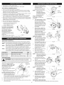
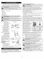
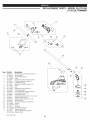
APPLICATIONS
As a trimmer:
Spark Plug
*
Cutting grass and light weeds
o
Edging
*
Decorative trimming around trees, fences, etc.
Other optional accessories may be used with this unit.
Starter Rope
Grip
Shaft Grip
On/Off
Control
D-Handle
\
\
Air Filter
Cover
\
Fuel
Cap
Throttle
Control
Shaft Housing
Primer Bulb
Convertible
TM
Coupler
Cutting
Head Shield
Cutting
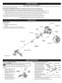
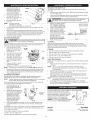
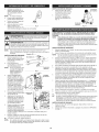
iNSTALL CUTTING HEAD SHIELD
-_L_J
the ARNING:
trimmer without
the cutting
head
shield injury,
in place.
To prevent
serious
personal
never operate
Use the following
installed.
1.
2.
3.
iNSTALL AND ADJUST
instructions
if the cutting head shield on the unit is not
Place the cutting head shield
onto the guard mount
bracket, making sure to align
the holes on the shield with
the ones in the guard mount
bracket. (Fig. 1)
Take the 2 shield screws and
screw each one into the
shield until finger tight.
Using an appropriate screw
driver, tighten the screws until
the shield is firmly in place.
•
Cutting
XX
Screw
_
i
Push the D-handle down onto
2.
hex bolt hole in the handle
should
on the left
the shaftbehousing
(Fig.side.
2). The _..___._
Insert the bolt into the hex
(2)
Guard
HeadShie,d
\ \ BrackeM°Untt
Fig. 1
THE D-HANDLE
1.
hole in the handleand push
through. Place the washer on
the bolt, then screw the wing
nut onto the bolt. Do not
tighten until making the
handle adjustment.
Shaft Grip
Shaft Housing
D-Handle
_"kJ_,,__/_-._
Minimum 6in.
--"_'J_{_-_
(15.24 cm)
Tighten
Wing
_-"_
Bolt _
Nut
Washer
3.
Rotate the D-handle to place
Fig. 2
the grip above the top of the
shaft housing. Place it a minimum of 6 inches (15.24 cm) from the end
of the shaft grip.
4.
While holding the unit in the operating position (Fig. 11), move the D-handle
to the location that provides the best grip.
5.
Tighten the wing nut until the D-handle is secure.
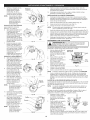
OPERATING
THE CONVERTIBLE
TM
COUPLER
SYSTEM
OIL AND FUEL MIXING
using any attachment,
the manual that came with the attachment. Follow all safety
j
_WARNING:
Before
read and understand |
nformat on conta
ned w th n.
d
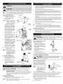
The Convertible
TM
coupler system enables the use of these optional attachments.
m
Edger
Cultivator
_L_
Turbo Blower
• Hedge Trimmer
WARNING:
unit, shut the
_-_,
2.
3.
Turn the knob
counterclockwise
Press and hold the release
button (Fig. 5).
While firmly holding the upper -shaft 4).
housing, pull the
(Fig.
attachment straight out of the
Convertible TM coupler (Fig. 3).
release
he
t
hat
t
re
su
_
It is recommended to use the manufacturers 2-cycle oil with this unit. If
unavailable, use a good 2-cycle oil designed for air-cooled engines along
with a fuel additive, such as STA-BIL® Gas Stabilizer or an equivalent. Add
0.8 oz. (23 ml.) of fuel additive per gallon of fuel according to the instructions
on the container. NEVER add fuel additives directly to the unit's fuel tank.
\
Lower Shaft
Mixing The Fuel
Thoroughly mix the proper ratio of
2-cycle engine oil with unleaded
fuel in a separate fuel can. Use a
40:1 fuel/oil ratio. Do not mix them
directly in the engine fuel tank. See
the table for specific gas and oil
mixing ratios.
iF... the unit came with a bottle
of 2-cycle oil; pour the entire
bottle into 1 gallon of gas
and mix thoroughly.
90° Edging Hole
(Trimmer Only)
NOTE:
Fig. 4
NOTE:
OR OTHER ATTACHMENT
Release Button
TM
manual
Drain the tank and run the engine dry before storing the unit
Using Fuel Additives
Housing
Convertible
Coupler
follow
Always agitate the fuel mix before fueling the unit
Fig. 3
ATTACHMENT
to loosen
--
Housing
For decorative edging with the line
head trimmer attachment or other
attachment, lock the release
button of the attachment into the
90 ° hole (Fig. 4).
1.
If choosing to use a blended fuel, or its use is unavoidable,
recommended precautions:
Always use the fresh fuel mix explained in the operator's
"_a
""1 I - _,
------Q4_'__----_----_
Upper Shaft
--
Aligning the release
button with the guide
recess will help
installation (Fig. 5).
Turn the knob clockwise to
tighten (Fig. 4).
THE TRIMMER
be
,
nit
u
i
J,.I
Fuels
reliability, pay strict attention to the oil and fuel mixing instructions
on the 2-cycle oil container. Using improperly mixed fuel can
AUTION: For proper engine operation and maximum
severely damage the engine.
_
Primary Hole
\
\
\.
_
_
J-"_,
bench.
Turn knob counterclockwise
to loosen (Fig. 4).
While firmly holding the
attachment, push it straight
into the Convertible TM
coupler until the release
button snaps firmly into the
primary hole (Fig. 3).
he
t
Before
To make installing or
removing the attachment
easier, placethe unit on
the ground or on a work
REMOVING
Using Blended
into the primary hole, and that the knob is
NOTE:
3.
OR OTHER ATTACHMENT
To avoid
serious
personal
injury andattachment.
damage to the JJ
unit
off before
removing
or installing
=
CAUTION
_
2.
ATTACHMENT
button is fully snapped
securely tightened.
NOTE:
1.
THE TRIMMER
o_erating
_
10%
ethanol will
likelybeen
damage
thisthat
engine
and void thegreater
warranty.
ARNING"
It has
proven
fuel containing
than
Today's fuels are often a blend of gasoline and oxygenates such as ethanol,
methanol, or MTBE (ether). Alcohol-blended fuel absorbs water. As little as 1%
water in the fuel can make fuel and oil separate. It forms acids when stored.
When using alcohol-blended fuel, use fresh fuel (less than 30 days old).
Brushcutter
Pole Saw
INSTALLING
INSTRUCTIONS
Old and/or improperly mixed fuel are the main reasons for the unit not
running properly. Be sure to use fresh, clean unleaded fuel. Follow the
instructions carefully for the proper fuel/oil mixture.
Definition of Blended Fuels
_
. --
UNLEADED GAS
-
r
2 CYCLE OIL
f GALLON US
(3.8 LITERS)
3.2 FL. OZ.
(95 ml)
f LITER
25 ml
One gallon (3.8 liters) of
MIXING
RATIO = 40:1
unleaded fuel mixed with
one 3.2 oz. (95 ml.) bottle of 2-cycle oil makes a 40:1 fuel/oil ratio.
Dispose of the old fuel/oil mix in accordance
Local regulations.
to Federal, State and
may explode. Always stop the engine and allow it to cool before
filling the fuel tank. Do not smoke while filling the tank. Keep
ARNING: Gasoline is extremely flammable. Ignited vapors
sparks and open flames at a distance from the area.
FUELING THE UNIT
_l
Guide
_
spray.
Never operate
the fuel
unit cap
without
capinjury
securely
place.
WARNING:
Remove
slowlythetofuel
avoid
from infuel
_
up any spilled fuel immediately. Avoid creating a source of ignition for
WARNING:
a clean,
well
outdoor area. Wipe
spilt fuel. Do notAdd
startfuel
the inengine
until
fuelventilated
vapors dissipate.
1.
Turn unit on its side, with the fuel cap facing up, and remove the fuel cap.
Recess
Fig. 5
2.
Place the gas container's spout into the fill hole on the fuel tank and fill
the tank (Fig. 6).
NOTE: Do not overfill the tank.
3.
Wipe up any gasoline that
may have spilled.
4.
5.
Reinstall the fuel cap.
Move the unit at least 30 ft.
(9.1 m) from the fueling
source and site before
starting the engine.
Fig. 6
5
i
m
A
I WARNING:
_
Operate this unit only in a well-ventilated outdoor area.
Carbon monox de exhaust fumes can be ethan
i
NOTE:
Fully press and release the primer bulb 10 times, slowly. Some amount of
fuel should be visible in the primer bulb and fuel lines (Fig. 8). If fuel can not
be seen in the bulb, press and release the bulb as many times as it takes
until fuel can be seen in it.
4.
5.
Flip the choke lever clockwise until it clicks (Fig. 9).
Crouch in the starting position (Fig. 10). Do not squeeze the throttle. Place
the Plug-In Power Start or Power Bit Start into the back of the unit.
Refer to the Operation section of the Plug-In Power Start or Power Bit
Start operator's manual.
6.
Press and hold the ON (I) button of the Plug-in Power Start or Power Bit
Start equipped drill in intervals no longer than 4 seconds each until the
unit starts.
7.
Wait and allow the unit to idle for 5 - 10 seconds. If the unit stops running
during this time, squeeze the throttle control, then press and hold the ON (I)
button of the Plug-in Power Start or Power Bit Start equipped drill in intervals
no longer than 4 seconds each until the unit starts.
a conf ned area. j
starting position when pulling the starter rope (Fig. 10). To avoid seriousl
! WARNING:
Avoid accidental starting. Make sure to be in the 1
injury, the operator and unit must be in a stable position while starting.
I _hb
3.
This unit uses the Incredi-PulF M starting system, which significantly
reduces the effort required to start the engine.
STARTING INSTRUCTIONS
off (o)
1.
Mix gas with oil. See Oil and
Fuel Mixing Instructions.
2.
Fill the fuel tank with the
fuel/oil mixture.
NOTE:
There is no need to turn
the unit on. The On/Off
Control is in the ON ( I )
position at all times (Fig. 7).
3.
4.
5.
Fully press and release the
primer bulb 10 times, slowly.
Some amount of fuel should
be visible in the primer bulb
and fuel lines (Fig. 8). If fuel
can not be seen in the bulb,
press and release the bulb as
many times as it takes until
fuel can be seen in it.
Flip the choke lever clockwise
8.
9.
Control
Remove the Plug-In Power Start or drill from the unit.
Squeeze and hold the throttle control for 30 to 60 seconds to allow the
unit to warm up.
IF,..
The engine does not start, go back to step 3.
IF,..
The engine fails to start after a few attempts, squeeze the throttle
control, then press and hold the Plug-In Power Start or drill ON (I)
button in intervals no longer than 4 seconds each until the unit starts.
Fig. 7
.p.
_
_
_
_
_
h
_
\
j
Primer
Bulb
_\
_1
until it clicks (Fig. 9).
II
I_-'-__
Crouch in the starting position
II
_. I
(Fig. 9). Do not squeeze the
_ t
/_
"___
throttle. Pull the starter rope
_/_d/__
with a controlled motion until
\_
_/l_6_q_'__
the unit starts.
Wait and allow the unit to idle for
5 - 10 seconds. If the unit stops
Choke
LeverJ
running during this time, squeeze
the throttle control and pull the
starter rope in a controlled
motion until the unit starts.
/
Release the throttle control and allow the engine to cool down by idling.
2.
Press and hold the On/Off Control in the OFF (O) position until the
engine comes to a complete stop (Fig. 7).
HOLDING
--
Fig. 8
INSTRUCTIONS
1.
__-
_
THE UNIT
to reduce
the risk
of injury
this and
unit.body protection
ARNING:
Always
wearwhen
eye, operating
hearing, foot
Before operating the unit, stand in
the operating position (Fig. 11).
Check for the following:
The operator is wearing eye
protection and proper clothing
With a slightly-bent right arm,
the operator's hand is holding
the shaft grip
Squeeze and hold the throttle
control for 30 to 60 seconds to
allow the unit to warm up.
The engine does not start,
go back to step 3.
NOTE:
If the unit is hot and fails
to start within 3 pulls of
the starter rope, squeeze
the throttle control and
pull the starter rope until
the unit starts.
STOPPING
IF,==
STOPPING
1.
2.
The operator's left arm is
straight, the left hand holding
the D-handle
• The unit is at waist level
Fig. 9
Starting
Position
,_
Fig. 11
The cutting head is parallel to
the ground and easily contacts the grass without the need to bend over
ADJUSTING
TRIMMING
LINE LENGTH
INSTRUCTIONS
Release the throttle control
and allow the engine to cool
down by idling.
Press and hold the On/Off
Control in the OFF (O)
position until the engine
comes to a complete stop
(Fig. 7).
assembly. Excessive line length will cause premature engine
failure and / or unit damage.
Fig. 10
The Bump Head TM cutting head
allows the release of trimming line
without stopping the engine. To
release more line, lightly tap the
cutting head on the ground (Fig.
12) while operating the unit at high
speed.
NOTE:
HOW TO START THE UNiT USING THE PLUG-IN
POWER BiT START ACCESSORY
NOTE=
POWER START OR
This unit can use a Plug-in Power Start or Power Bit Start
optional accessory!
Please refer to the Plug-In Power Start or Power Bit Start operator's
manual for proper use of this feature. (Items may be Sold Separately!
Please refer to page 8 of this manual about purchasing these
accessories.)
STARTING INSTRUCTIONS
1.
Mix gas with oil. See Oil and Fuel Mixing Instructions.
2.
Fill the fuel tank with the fuel/oil mixture.
NOTE:
There is no need to turn the unit on. The On/Off Control is in the
ON (I) position at all times (Fig. 7).
Always keep the trimming
line fully extended. Line
release becomes more
_,
difficult when the cutting
line gets shorter.
Each time the head is bumped,
Fig. 12
about 1 inch (25.4 mm) of trimming line releases. A blade in the cutting head
shield will cut the line to the proper length if any excess line is released.
For best results, tap the bump knob on bare ground or hard soil. If
attempting a line release in tall grass, the engine may stall.
NOTE:
Do not rest the Bump Head
Some line breakage will occur from:
Entanglement with foreign matter
Normal line fatigue
TM
on the ground while the unit is running.
]
• Attempting
tocutthick,
stalky
weeds
Forcing
thelineintoobjects
such
aswalls
orfence
posts
TiPS FOR BEST TRiMMiNG
Check the indexing teeth on
the inner reel and outer spool
for wear (Fig. 16). If
necessary, remove burrs or
replace the reel and spool.
NOTE:
Always use the correct
line length when
installing trimming line
on the unit. The line may
not release properly if
the line is too long.
RESULTS
• Keep the cutting head parallel to the ground.
Do not force the cutting head. Allow the tip of the line to do the cutting,
especially along walls. Cutting with more than the tip will reduce cutting
efficiency and may overload the engine.
Cut grass over 8 inches (200 mm) by working from top to bottom in small
increments to avoid premature line wear or engine drag.
• Cut from right to left whenever possible. Cutting to the left improves the
unit's cutting efficiency. Clippings are thrown away from the operator.
6.
Take approximately 20 feet (6
m) of new trimming line, loop
it into two equal lengths.
Insert each end of the line
through one of the two holes
in the inner reel (Fig. 17). Pull
the line through the inner reel
so that the loop is as small
as possible.
7.
Wind the lines in tight even
layers onto the reel (Fig. 18).
Wind the line in the direction
indicated on the inner reel.
Place an index finger
between the two lines to stop
the lines from overlapping.
Do not overlap the ends of
the line. Proceed to step 12.
Trim only when grass and weeds are dry.
upon:
Following the trimming techniques
What vegetation is being cut
Where vegetation is cut
For example, the line will wear
faster when trimming against a
foundation wall as opposed to
trimming around a tree.
DECORATIVE
TRIMMING
Decorative trimming is
accomplished by removing all
vegetation around trees, posts,
fences, etc.
Fig. 13
Rotate the whole unit so that the
cutting head is at a 30 ° angle to the ground (Fig. 13).
MAINTENANCE
SplitUne® installation
8.
Take approximately 10 feet (3
m) of new trimming line. Insert
one end of the line through
one of the two holes in the
inner reel (Fig. 19). Pull the
line through the inner reel until
only about 4 inches is left out.
9.
Insert the end of the line into
the open hole in the inner
reel and pull the line tight to
make the loop as small as
possible (Fig. 19).
SCHEDULE
Perform these required maintenance procedures at the frequency stated in
the table. These procedures should also be a part of any seasonal tune-up.
NOTE:
Some maintenance procedures may require special tools or skills. For
these types of repairs call 1=800-4-MY=HOME® for more information.
NOTE:
Please read the California/EPA statement that came with the unit
for a complete listing of terms and coverage for the emissions
control devices, such as the spark arrestor, muffler, carburetor, etc.
NOTE:
Please read the California/EPA statement that came with the unit
for a complete listing of terms and coverage for the emissions
control devices, such as the spark arrestor, muffler, carburetor, etc.
FREQUENCY
MAINTENANCE
REQUIRED
Every 10 hours
Clean and re-oil air filter
p. 9
Every 25 hours
Check spark plug condition and gap
p. 10
10.
Before winding, split the line
back about 6 inches.
11.
Wind the line in tight even
layers in the direction
indicated on the inner reel.
SEE
NOTE:
12.
rope. These can Never
break use
off and
become dangerous
projectiles.
WARNING:
metal-reinforced
line, wire,
chain or
i
13.
This section covers both SplitLine@ and standard single line installation.
Always use original equipment
manufacturer 0.095 in. (2.41 ram)
replacement line. Line other than
the specified may make the
engine overheat or fail.
Bump Knob
Install a prewound inner reel
Removing the Existing Inner Reel
2.
3.
4.
Failure to wind the line in
the direction indicated will
Insert the split ends of the
line into the two holding slots
(Fig. 20).
Insert or slide the split ends
of the line through or into the
eyelets in the outer spool and
place inner reel with spring
inside the outer spool (Fig.
21). Push the inner reel and
outer spool together.
NOTE:
There are two methods to replace
the trimming line:
• Wind the inner reel with new line
1.
Inner Reel
Fig. 15
Indexing
Teeth
Fig. 16
Loop
Fig. 17
Fig. 18
cause the cutting head to
operate incorrectly.
LiNE INSTALLATION
--
Spring
Single Line installation
Go To Step 8 for SplitLine®
Installation:
Slowly move the unit into and out of the cutting area at the desired height.
Move either in a forward-backward
or side-to-side motion. Cutting shorter
lengths produces the best results.
• The life of the cutting line is dependent
Outer
Hold the outer spool with one
hand and unscrew the bump
Fig. 14
knob counterclockwise
(Fig. 14). Inspect the bolt inside the bump knob
to make sure it moves freely. Replace the bump knob if damaged.
Remove the inner reel from the outer spool (Fig. 15).
Remove spring from the inner reel (Fig. 15).
The spring
assembled
reel before
the cutting
Loop
Fig. 19
must be
on the inner
reassembling
head.
14.
While holding the inner reel
and outer spool, grasp the
split ends and pull firmly to
release the line from the
holding slots in the spool.
15.
Hold the inner reel in place
and install the bump knob by
turning clockwise. Tighten
securely.
Index
Fig. 20
INSTALLING A PREWOUND REEL
1.
Hold the outer spool with one hand and unscrew the bump knob
Use a clean cloth to clean the inner reel, spring, shaft, and inner surface
of the outer spool.
7
Teeth
2.
3.
counterclockwise (Fig. 14).
Inspect the bolt inside the
bump knob to make sure it
moves freely. Replace the
bump knob if damaged.
Remove the old inner reel from
the outer spool (Fig. 15).
REPLACING
Eyelets
2.
Remove the spring from the
old inner reel (Fig. 15).
Clean around the spark plug. Remove the spark plug from the cylinder
head by turning a 5/8-inch socket counterclockwise.
i
A
I WARNING:
4.
Place the spring in the new
inner reel.
NOTE:
The spring must be
assembled on the inner
reel before reassembling
Fig. 21
3.
Replace a cracked, fouled or
dirty spark plug. Set the air
gap at 0.025 in. (0.635 rnrn}
using a feeler gauge (Fig. 25).
4.
Install a correctly-gapped
spark plug in the cylinder
head. Tighten by turning the
5/8-inch socket clockwise
until snug. If using a torque
wrench, torque to:
the cutting head.
Insert or slide the ends of the line through or into the eyelets in the outer
spool (Fig. 21).
6.
Place the new inner reel inside the outer spool. Push the inner reel and
outer spool together. While holding the inner reel and outer spool, grasp the
ends and pull firmly to release the line from the holding slots in the spool.
Hold the inner reel in place and install the bump knob by turning
clockwise. Tighten securely.
AIR FILTER MAINTENANCE
-[_
andARNING:
allow it to coolTo
before
or maintaining
avoid cleaning
serious personal
injury, it.
always turn the unit off
Failure to maintain the air filter properly can result in poor performance
can cause permanent damage to the engine.
1.
2.
3.
4.
Open the air filter cover by
pressing the lock tab in and
pulling out on the air filter
cover (Fig. 22).
or
Air Filter
Cover
Tab
Air
Apply enough clean SAE 30
motor oil to lightly coat the
filter.
Filter
6.
Replace the air filter into the base plate (Fig. 22).
Fig. 22
• Never store a fueled unit where fumes may reach an open flame or spark.
• Allow the engine to cool before storing.
Careless adjustments can seriously damage the unit. An authorized
service dealer should make carburetor adjustments.
If, after checking the fuel mixture and cleaning the air filter, the engine still
will not idle, adjust the idle speed screw as follows:
1.
Start the engine and run for
one minute to warm up.
Refer to Starting/Stopping
Instructions.
use or damage.
• Store the unit in a dry, well-ventilated area.
Store the unit out of the reach of children.
LONG TERM STORAGE
time, use the following storage
Removing the fuel cap, tip the unit and drain the fuel into an approved
container.
NOTE:
The idle speed of the engine is adjustable. An idle adjustment screw is
between the air filter cover and the engine starter housing (Fig. 17).
Do not use gas that has been stored for more than 30 days.
Dispose of the old gasoline in accordance to Federal, State, and
Local regulations.
2.
Start the engine and allow it to run until it stalls. This ensures that all
fuel has been drained from the carburetor.
3.
Allow the engine to cool. Remove the spark plug and put 5 drops of
high quality motor oil into the cylinder. Pull the starter rope slowly to
distribute the oil. Reinstall the spark plug.
NOTE:
4.
Remove the spark plug and drain all of the oil from the cylinder before
attempting to start the trimmer after storage.
Thoroughly clean the unit and inspect it for any loose or damaged
parts. Repair or replace damaged parts and tighten loose screws, nuts
or bolts. The unit is ready for storage.
PLUG=IN POWER START AND POWER BIT START FEATURES
Release the throttle trigger and
let the engine idle. If the engine
stops, insert a small phillips
screwdriver into the idle
Idle Speed
Screw
adjustment screw (Fig. 17).
Turn the idle speed screw
clockwise 1/8 of a turn at a
time (as needed) until the
Fig. 23
engine idles smoothly.
If the engine appears to be idling too fast, turn the idle speed screw
counterclockwise
1/8 of a turn at a time (as needed), to reduce idle
speed.
Checking the fuel mixture, cleaning the air filter and adjusting the idle speed
should solve most engine problems. If not and all of the following are true:
This unit can be started with an optional
Plug-In Power Start or Power Bit Start (may
be sold separately). If choosing to start the
unit using one of these features or have
questions, please contact your local
Craftsman retailer or call 1-800=4-MY=
HOME@ for more information and purchasing.
You may also go to www.craftsman.com.
the engine will not idle
service dealer.
!
1
Power
Item No.
316.85951
316.85952
• the engine hesitates or stalls on acceleration
there is a loss of engine power
adjusted by an authorized
Use a small brush to clean off the outside of the unit. Do not use strong
detergents. Household cleaners that contain aromatic oils such as pine and
lemon, and solvents such as kerosene, can damage plastic housing or handle.
Wipe off any moisture with a soft cloth.
1.
NOTE:
Operating the unit without the air filter WILL VOID the warranty.
7.
Reinstall the air filter cover. Position the two small tabs on the air filter
cover into the two slots in the base plate and press the air filter cover
down, making sure to align the lock tab with the lock tab slot, until it
snaps into place (Fig. 22).
IDLE SPEED ADJUSTMENT
Have the carburetor
CLEANING
If planning on storing the unit for an extended
procedure:
Squeeze the filter to spread
and remove excess oil.
3.
|J
Fig. 24
• Store the unit locked up to prevent unauthorized
5.
2.
1
5.
110-120 in.olb. (12.3=13.5
N_rn). Do not over-tighten.
Reattach the plug boot.
i
STORAGE
Remove the air filter (Fig. 22).
Wash the filter in detergent
and water. Rinse the filter
thoroughly and allow it to dry.
NOTE:
Do not sand blast, scrape or clean spark plug
e ectrodes. Grt n the eng ne cou d damage the cy rider.
5.
7.
THE SPARK PLUG
Use a Champion RDJ7J or a replacement part #753-06193 spark plug (or
equivalent).
1.
Stop the engine and allow it to cool. Grasp the plug boot firmly and pull
it from the spark plug.
Start
Feature
Description
.....................................
........................................
Plug-In Power Start
Power Bit Start
PROBLEM
SOLUTION
Empty
fueltank
Fill fuel tank with properly mixed fuel
OldFuel
Drain fuel tank and add fresh fuel mixture
Airfilterisplugged
Replace or clean the air filter
Old Fuel
Drain gas tank and add fresh fuel
e
Cutting head bound with grass
Stop the engine and clean cutting head
Inner reel bound up
Rewind the inner reel
Line welded
Disassemble, remove the welded section and rewind
Not enough line is exposed
Push the bump knob and pull out line until 4 inches (102 mm) of line is
outside of the cutting head
9
Engine Type ...................................................................................................
Air-Cooled,
Displacement
.............................................................................................................
Operating RPM .......................................................................................................
27 cc
6,800+ rpm
Idle Speed RPM .................................................................................................
2,800 - 3,400 rpm
Spark Plug Gap ................................................................................................
Lubrication .......................................................................................................
0.025 in. (0.635 mm)
Fuel/Oil Mixture
Fuel/Oil Ratio ...............................................................................................................
Fuel Tank Capacity
40:1
................................................................................................
14 fl.oz. (414 ml)
Approximate Unit Weight (No fuel) ......................................................................................
Trimming Line Diameter ..........................................................................................
10 Ibs. (4.5 kg)
0.095 in. (2.41 mm)
Cutting Path Diameter ..............................................................................................
All specifications
notice.
are based on the latest product information
REPAIR PROTECTION
17 in. (43.18 cm)
available at the time of printing. We reserve the right to make changes at any time without
AGREEMENTS
Congratulations on making a smart purchase. Your new Craftsman@ product is designed and manufactured for years of dependable operation.
products, it may require repair from time to time. That's when having a Repair Protection Agreement can save you money and aggravation.
Here is what the Repair Protection Plan Agreement includes:
[]
Expert
[]
Unlimited
service
[]
Product
[]
Discount
preventive
2-Cycle
by our 10,000
service
professional
and no charge
replacement
of 10% from
maintenance
for parts
up to $1500
regular price
checks
if your
repair
specialists
and labor
cover
of service
But like all
on all covered
product
and related
repairs
can not be fixed
installed
parts not covered
by the agreement;
also,
10% off regular
price of
[]
Fast help by phone - we call it Rapid Resolution
- phone support from a Sears representative.
Think of us as a "talking owner's
manual."
Once you purchase the Repair Protection Agreement, a simple phone call is all that it takes for you to schedule service. You can call anytime day or night, or
schedule a service appointment online.
The Repair Protection Agreement is a risk-free purchase. If you cancel for any reason during the product warranty period, we will provide a full refund. Or a prorated
refund anytime after the product warranty period expires. Purchase your Repair Protection Agreement today!
Some limitations and exclusions apply. For prices and additional information call 1 =800-827=6655.
*Coverage in Canada varies
Sears Installation
Service
on some items. For full details call Sears Canada at 1-800-361-6665.
For Sears professional installation of home appliances, garage door openers, water heaters, and other major home items, in the U.S.A. or Canada call 1-800-4-MY-HOME ®.
10
Manual
del Operador
MRN
2-Tiempos
RECORTADOR A WEEDWACKER_
Model No. 316.791191
INCREDI.PULU_AU-P
UNBELIEVABLE
STARTING
EA S E
TM
• SEGURIDAD
MONTAJE
FUNCIONAMIENTO
MANTENIMIENTO
LISTADO DE PIEZAS
PRECAUCION: Lea el manual
del operador y siga todas ias
advertencias
e instrucciones
de seguridad.
Sears Brands
Management
Corporation,
Visite nuestro
769-06344
P01
Hoffman
Estates,
IL 60179 U.S.A.
sitio web: www.craftsman.com
6/11
PROPOSlCION
65 DE CALIFORNIA
Los simbolos de seguridad se utilizan para Ilamar su atenci6n sobre posibles
peligros. Los simbolos de seguridad y sus explicaciones merecen toda su
atenci6n y comprensi6n. Los simbolos de seguridad no eliminan ningQn peligro
por s[ mismos. Las instrucciones o advertencias que ofrecen no substituyen
las medidas adecuadas de prevenci6n de accidentes.
LAS EMISIONES DEL MOTOR DE ESTE PRODUCTO CONTIENEN
SUBSTANCIAS QUIMICAS QUE EL ESTADO DE CAUFORNIA CONOCE
COMO CAUSANTES DECANCER, DEFECTOS DE NACIMIENTO U OTROS
DANOS REPRODUCTIVOS.
SIMBOLO
precauci6n. Debe
atencion para evitar
graves
lesiones o
ALERTA
DE prestar
SEGURIDAD:
Indica sufrir
peligro,
advertencia
personales. Puede set utilizado junto con otros simbolos o figuras.
INDICE DE CONTENIDOS
Normas para una operaci6n segura ..............................
Garantia
...................................................
Conozca su unidad ...........................................
Instrucciones de ensamble .....................................
Informaci6n del aceite y del combustible ..........................
Instrucciones de arranque y apagado ............................
Instrucciones de operaci6n
....................................
Instrucciones de mantenimiento y reparaci6n ......................
Limpieza y almacenamiento
....................................
Resolucion de problemas ......................................
Especificaciones
.............................................
Lista de piezas ..............................................
Numeros de servicio ................................
14
16
16
16
17
18
19
19
21
22
23
30
Contraportada
NOTA:
Le ofrece informaci6n o instrucciones que son esenciales para la
operaci6n o mantenimiento del equipo.
PELIGRO"
El no obedecer una advertencia de seguridad puede
conducir a que usted u otras personas sufran graves lesiones. Siga
siempre las precauciones de seguridad para reducir el rJesgo de
incendio, descarga el6ctrica y lesiones personaJes.
ADVERTENCIA"
El no seguir una advertencia de seguridad
puede conducir a que usted u otras personas sufran lesiones. Siga
siempre las precauciones de seguridad para reducir el riesgo de
incendio, descarga el6ctrica y lesiones personales.
PREOAUOION:
El no seguir una advertencia de seguridad
puede conducir a daSo patrimonial o a que usted u otras
personas sufran lesiones personales. Siga siempre las
precauciones de seguridad para reducir el riesgo de incendio,
descarga el6ctrica y lesiones personales.
PARACHISPAS
NOTA: Para los usuarios en tierras forestales de los EE.UU. yen los estados de
California, Maine, Oregon y Washington. Todos los terrenos forestales de los EE.UU.
y el estado de California (C6digos de Recursos Publicos 4442 y 4443), Oregon y
Washington, requieren por decreto, que ciertos motores de combusti6n intema que se
hagan funcionar en zonas boscosas y/o zonas cubiertas por pastizales, esten
equipados con un parachispas, que sean mantenidos en buen estado de
funcionamiento o que el motor sea construido, este equipado y sea mantenido para
evitar incendios. Consulte los reglamentos pertinentes a esos requisitos con las
autoridades estatales o locales. El incumplimiento de esos requisitos puede
responsabilizarle o someterle a la imposici6n de una multa. Esta unidad rue equipada
en la f_brica con un parachispas. Si requiere sustituci6n, hay una Pantalla
Parachispas disponible, Pieza #753-06182 al contactar el departamento de servicio.
NOTA:
Toda la informaci6n, las ilustraciones y las especificaciones contenidas en este
manual se basan en la informaci6n mas reciente disponible en el momento de
impresi6n del manual. Nos reservamos el derecho de hacer cambios en cualquier
momento sin aviso previo.
ANTES DE OPERAR LA UNIDAD
DE SEGURIDAD
=
Aleje a los niSos, personas presentes y animales dom6sticos del &rea;
mant6ngalos fuera de un radio de 50 pies (15 m) como minimo. AOn asi,
todavia corren el riesgo de ser alcanzados por los objetos que salen
despedidos. Sugiera a los presentes usar protecci6n para los ojos. Si
alguien se le acerca, apague la unidad de inmediato.
GENERAL
• Lea detenidamente las instrucciones.
uso adecuado de la unidad.
jEsta unidad puede utJJJzar un arrancador de potencia
electrico o el accesorio optional accesorio arrancador de
potencia para taladro!
Para informarse sobre el uso adecuado de estos sistemas, consulte
el manual del operador del arrancador de potencia electrico odel
accesorio opcional accesorio arrancador de potencia para taladro.
i(Articulos vendidos por separado)! Vea en la pagina 21 de este
manual mAs informaci6n sobre estos accesorios).
Lea eJ manual del operador y siga todas las advertencias
e instrucciones
de seguridad. De no hacerlo, el operador y/o los espectadores pueden
sufrir graves lesiones.
SJ TIENE PREGUNTAS, LLAME AL 1=800=4=MY=HOME®
o IMPORTANTE INFORMACION
LEA TODAS LAS INSTRUCCIONES
SEGURIDAD
SIGNIFICADO
Familiaricese con los controles y el
• Guarde estas instrucciones. ConsQItelas con frecuencia y utilicelas para
instruir a otros usuarios. Si le presta esta unidad a otras personas,
pr6stele tambi6n estas instrucciones.
Inspeccione cuidadosamente
el &rea antes de encender la unidad. Retire
las piedras, vidrios rotos, clavos, alambres, cadenas y otros objetos que
podrian salir despedidos o enredarse en la unidad.
• No opere esta unidad siesta cansado, enfermo o bajo los efectos del
alcohol, drogas o medicamentos.
Apriete el control del regulador y compruebe que regrese
automaticamente a la posici6n de marcha en vacio. Haga todos los
ajustes o reparaciones antes de usar la unidad.
Apague siempre la unidad cuando la operaci6n se demore o al caminar
de un lugar a otro.
Sostenga siempre la unidad con ambas manos al operarla. Agarre
firmemente ambas manijas o empuSaduras.
• Los niSos y adolescentes menores de 15 a5os no deben usar la unidad.
Los adolescentes pueden hacerlo bajo la supervisi6n de un adulto.
• Use la herramienta correcta. Use esta herramienta solamente para el
prop6sito previsto.
• Use la unidad Qnicamente a la luz del dia o con buena luz artificial.
Lleve puestas gafas o lentes de seguridad que cumplan con las normas
ANSI Z87.1 y est6n marcados como tales. Use siempre protecci6n para
los oidos al operar esta unidad. P6ngase una mascara facial o contra el
polvo si la operaci6n levanta polvo.
No fuerce la unidad. El equipo funcionara mejor y con menos
probabilidad de accidentes a la velocidad para la que rue diseSado.
No intente alcanzar demasiado lejos ni Io use parado en superficies
inestables como escaleras, arboles, pendientes pronunciadas, techos,
etc. Mantenga siempre la posici6n y el equilibrio adecuados.
No opere la unidad a una velocidad mayor que la necesaria para realizar
el trabajo. No ponga a funcionar la unidad a alta velocidad si no Io estA
usando.
Use pantalones largos y gruesos, botas, guantes y camisa de mangas
largas. No use ropa holgada, alhajas, pantalones cortos, sandalias ni
ande descalzo. Asegure su cabello por encima del nivel de los hombros.
Inspeccione la unidad antes de utilizarla.
AsegQrese de que todos los sujetadores
Reemplace las piezas rajadas, melladas
No opere la unidad si tiene piezas flojas
Reemplace las piezas da5adas.
est6n en su sitio y asegurados.
o da5adas de cualquier forma.
o da5adas.
Si la unidad golpea o se enreda con un objeto extraSo, pare
inmediatamente la unidad y compruebe si ha habido algen daSo. No
ponga a funcionar el equipo antes de reparar el daSo. No opere la unidad
si tiene piezas fiojas o daSadas.
Mantenga la unidad limpia de vegetacion y otros materiales que puedan
obstruir, pegar o atorar las piezas en movimiento, Io que podria ocasionar
lesiones personales graves o daSos a la unidad.
Todos los los accesorios de protecci6n y seguridad deben estar
correctamente instalados antes de comenzar a operar la unidad.
,, Utilice solamente las piezas o accesorios de repuesto recomendados
para esta unidad, distribuidos por Sears o una tienda Craftsman. Usar
cualquier otra pieza o accesorio de repuesto comprada en otra parte
puede ser peligroso y anulara su garantia.
Mantenga las manos, la cara y los pies lejos de todas las partes m6viles.
No trate de tocar ni detener ninguna de las piezas m6viles mientras est6n
girando.
,, Tenga en cuenta el riesgo de lesiones a la cabeza, las manos y los pies.
12
• Deje que la unldad se enfrie antes de almacenarla o transportarla.
Cerclorese de asegurar la unldad al transportarla.
• No guarde nunca la unldad con combustible en el tanque nl dentro de una
edlflcaclOn en la que los gases puedan ponerse en contacto con una
llama expuesta (luces photos, etc.) o chlspas 0nterruptores, motores
electncos, etc.).
• No moje nunca nl rocie la unldad con agua nl con nmgL]n otro liquldo.
Mantenga las manuas secas, hmplas y sHqsucledades. Limple la unldad
despues de cada use, lea las Instrucclones de Dmpleza y
almacenamlento.
• Para ewtar el pehgro de mcendlo, reemplace el sHenclador y parachlspas
defectuosos. Mantenga el motor y el sllenclador sm hlerbas, hojas, grasa
exceslva e incrustaclones de carbon.
• Guarde la unldad en un lugar seco, bajo Ilave o en alto, a fin de evltar su
uso no autonzado o da_o. Mantengala fuera del alcance de los nines.
SEGURIDAD
_
SOBRE EL ACEITE Y COMBUSTIBLE
pueden
explotarNCIA:
sl se enclenden
Tome
DVERTE
La gasohna
es las
muyslgulentes
inflamableprecauclones
y sus gases
]
• Almacene el combustible solamente en los rec@lentes @se_ados y
aprobados especiflcamente para estos matenales.
• Pare slempre el motor y deje que se enfrie antes de Ilenar el tanque de
combustible. No quite nunca la tapa del tanque de combustible nl eche
combustible cuando el motor este cahente. No opere nunca la unldad sl la
tapa del combushble no esta blen asegurada en su lugar.
• No toque el motor, el bastldor del engranaje nl el sHenclador. Estas partes
se ponen extremadamente cahentes durante el funclonamlento y aun
despues de apagada la unldad.
• Esta unldad tlene un embrague. El accesono de la unldad permanece
estaclonano cuando el motor esta en marcha en vacio. De no hacerlo. Ileve
la unldad a Sears o a otro dlstnbuldor de serwclo cahflcado para su ajuste.
• Apague el motor y desconecte
una reparaclon.
SEGURIDAD
• Mezcle o eche slempre el combushble en un Area exterior blen ventHada y
hmpla, donde no haya chlspas nl llamas. No fume.
• No opere nunca la unldad sl la tapa del combushble
asegurada en su lugar.
• Evlte los arranques accldentales. Debe estar en la poslclon de arranque
slempre que tire de la cuerda. El operador y la unldad deben estar en una
poslclOn estable durante el arranque. Consulte las Instrucclones de
arranque y apagado.
la bujia para darle mantenlmlento
o hacer
DE LA RECORTADORA
• El protector del accesono de la recortadora debe estar slempre en su sltlo
mlentras que se opere la unldad. No opere la unldad sin las dos lineas de
la recortadora extendldas y la linea correcta mstalada. No extlenda la linea
de corte mas alia de la Iongltud del protector.
• Ajuste la manua en Den la poslclOn que proporclone el meier agarre
poslble.
no esta blen
• Ewte el pehgro de mcendlo debldo a combustible derramado. Dmple de
mme@ato todo combustible derramado de la unldad antes de encenderla.
Antes de arrancar el motor, aleje la unldad a una @stancla de 30 pies (9.1
m) come minlmo del lugar de abasto de combustible. No fume.
• Antes de arrancar la umdad, asegL_rese de que el accesono
recortadora no este en contacto con nlngL]n objeto.
• Nunca arranque nl opere la umdad dentro de una habltacl6n o edlflclo
cerrados. Resplrar los gases de escape puede ser fatal. Opere esta
unldad solamente en un Area exterior blen ventHada.
de la
• Use sOlo linea de reemplazo del fabncante ongHqaldel equlpo con un dlametro
de 0.095 de pulgada (2.41 mm). Nunca use linea reforzada con metal, alambre
o soga. Se pueden romper y converhrse en proyectHes pehgrosos.
• Mantenga la unldad hmpla de vegetaclon y otros mater=ales. Pudleran
trabarse entre el accesono de la recortadora y el protector.
• Mantenga las manos, la cara y los pies lejos de todas las partes mOvlles. No
toque n_trate detener el accesono de la recortadora mlentras este glrando.
• Verlflque que la unldad no tenga fugas de combustible.
• Afloje la tapa del tanque de combustible lentamente para dlslpar la
preslon del mlsmo.
GUARDE ESTAS INSTRUCCIONES
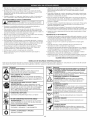
• SIMBOLOS
DE SEGURIDAD
E INTERNACIONALES
•
Este manual del operador describe los s[mbolos y flguras de segundad e mternaclonales que pueden aparecer en este producto.
para obtener mformaclOn completa acerca de la segundad, ensamble, operaclon y manten_m_ento y reparaclon.
SYMBOL
i MEANING
SYMBOL
SAFETY ALERT SYMBOL
Indicates danger, warn,ng or caution. May be used m
conjunction w,th other symbols or p_ctographs.
@
LEA EL MANUAL
Los objetos pequeifios pueden ser
lanzados a gran veloc_dad y ocas_onar bs_ones. Mant_ngase
olejado del rotor cuando est_ g_rando.
• MANTENGA ALEJADOS A LOS PRESENTES
ADVERTENCIA:
Lea el o los manuales del operador y
s_ga todas Hasadvertenc,as e mstrucc_ones de segundad. No
hacedo puede ocas, onar bs,ones graves al operador y/o a
Haspersonas presentes.
ADVERTENCIA:
Mantenga a todos los presentes,
espec,almente a los n,5os y an_mabs domOst,cos, a una
d_stanc,o de 50 p,es (15 m) como min_mo del Area de
operoc_6n.
PARA LOS OJOS Y O|DOS
Los objetos desped_dos y el ru=do
fuerte pueden ocas_onar bs_ones groves a los ojos y p_rdlda
de la aud,c,On. AI operar esta un_dad, Ibve puestas galas o
bntes de segundad que cumpian con Hasnormas ANSI
Z87.1-1989 y protecc_On para los oidos. De set necesano,
use un protector facial compbto.
• SUPERFHCHE CALHENTE
COMBUSTIBLE
• ACEITE
ADVERTENCIA:
ADVERTENCIA:
No toque nlnguno de los componentes
met_thcos del motor. El motor se pone extremadamente
cahente durante el func_onam_ento y puede ocas_onar graves
quemaduras. Deje que Haun_dad se enfrie compietamente
antes de hacerle cualqu_er manten_m,ento o serwc,o.
SIN PLOMO
Use s,empre combust,bb
hmp_o, fresco y s,n plomo
NO USE COMBUSTIBLE
E85 EN ESTA UNHDAD
Consuite el hpo de ace_te adecuado
operador.
Opnma 10 veces la pera del cebador, lentamente y por
compieto.
Se ha comprobado que es probable
que el combust_bb con mAs de 10% de etanol daOe este
motor, Io que anulara la garantia.
CONTROL
CONTROL
, CUCHILLA
DE ENCEND_DO Y APAGADO
ENCENDIDO /ARRANQUE
en el manual del
• PERA DEL CEBADOR
ADVERTENClA:
|
0
MEANING
, LOS OBJETOS QUE SALEN VOLANDO Y LA CUCHHLLA
GIRATOR_A PUEDEN OCASIONAR LESIONES GRAVES
ADVERTENCIA:
DEL OPERADOR
USE PROTECCION
Lea el manual del operador
AFILADA
ADVERTENCIA:
CuchHla aNada en el protector del
accesono de la recortadora. A fin de ewtar lesiones graves,
no toque nunca la cuchHla de corte de la linea.
/ FUNCIONAMIENTO
DE ENCENDHDO Y APAGADO
APAGADO o PARADO
13
GARANTIA
TOTAL
POR 2 A_IOS,
DE CRAFTSMAN
Este producto se garantiza DURANTE 2 ANOS a partir de la fecha de compra, contra defectos en el material o en la mano de obra. El producto defectuoso
sera reparado sin ningOn costo o serA remplazado gratuitamente si no puede ser reparado.
Para conocer los detalles sobre la cobertura de la garantia para que sea reparado o reemplazado,
visite el sitio web: www.craftsman.com
Esta garantia
cubre SOLAMENTE
defectos
en el material
o mano de obra.
La cobertura
de la garantia
NO incluye:
• Articulos consumibles que se desgasten debido al uso normal dentro del periodo de la garantia, tales como linea de corte, filtros o bujias de encendido.
DaNos que ocurran al producto como resultado de intentos de modificacion o reparacion por parte del usuario, o que sean causados por accesorios del producto.
Reparaciones necesarias debidas a accidente o falla en el funcionamiento,
o por no mantener el producto de acuerdo con todas las instrucciones
El mantenimiento preventivo, o reparaciones necesarias debido a mezcla incorrecta de combustible, o a combustible viejo o contaminado.
Esta garantia es nula si este producto se utiliza alguna vez durante la prestaci6n
Esta garantia le otorga a usted derechos
legales especificos,
de servicios de tipo comercial
provistas.
o si se le alquila a otra persona.
y usted puede ademAs poseer otros derechos, los cuales varian de un estado a otro.
Sears Brands Management
Corporation,
Hoffman Estates, IL 60179
APLICAClONES
Como recortadora;
.
Bujia
Corte de c6sped y hierbas delgadas
Recorte de bordes
de encendido
Manija
de la cuerda
de arranque
Mango del eje
. Recorte decorativo alrededor de Arboles, cercos, etc.
Puede usar otros accesorios con la unidad. Lea la lista de accesorios.
Control de encendido
y apagado
Manija
en
Cubierta
del filtro
D
de aire
combustible
Tapa
Control
Bastidor
del
eje
del
del
regulador
Bombilla
Convertible
del cebador
TM
acoplador
Protector
Cabezal
INSTALACION
de cabezal
de torte
de corte
DEL PROTECTOR
DE CABEZAL
DE CORTE
3.
!
_
Siga las siguientes instrucciones
instalado en su unidad.
1.
2.
1
protector de cabezal de corte colocado en su lugar para evitar
nunca la recortadora sin el
ADVERTENClA:
No opere
graves lesiones personales.
|
si el protector de cabezal de corte no estA
Coloque el protector del
cabezal de corte en el soporte
de montaje de protecci6n,
asegurandose de alinear los
orificios en el protector con los
del soporte de montaje de
protecci6n. (Fig. 1)
Tome los 2 tornillos del
protector y atornille cada uno
en el protector hasta que
quede apretado con la mano.
, ,
de cabezal
aeco e
INSTALAOION
1.
(2) Tornillos
\
\
/]
//
Soporte
Utilizando un destornillador apropiado, apriete los tornillos hasta que el
protector quede firme en su lugar. AsegOrese de que los tornillos est_n
apretados por igual, de manera que haya una separaci6n equilibrada
entre el soporte y el protector en cada lado.
Y AJUSTE DE LA MANIJA
Empuje la manija D hacia
abajo sobre el bastidor del eje
(Fig. 2). El agujero del perno
hexagonal en la manija debe
quedar en el lado izquierdo.
Inserte el perno de la manija
en el agujero hexagonal en la
manija y empOjela. Coloque
de
EN D
Mango
del
Bastidor del
eje
2.
\ \ z m°nt°jeiaerotecco.
la arandela en el perno,
luego enrosque la tuerca de
mariposa en el perno. No la
apriete hasta que haya
ajustado la manija.
Fig. I
3.
14
eje
.Manija en D
Ajuste
Minimo de
15,24 cm
(6 pulgadas}
Tuerca de
mariposa
Arandela
Perno
Fig. 2
Gire la manija en D para colocar el mango sobre la parte superior del
bastidor del eje. Col6quela a una distancia minima de 6 pulgadas
(15.24 cm) del extremo del mango del eje.
4. Mientras
sostiene
launidad
enlaposiciOn
defuncionamiento
(Fig.
10),
coloque
lamanija
enDenellugar
quelebrinde
elmejor
agarre.
5. Apriete
latuerca
demariposa
hasta
quelamanija
enDquede
firme.
OPERACION
DEL
SISTEMA DEL ACOPLADOR CONVERTIBLE
DefiniciOn
__
TM
/
i
El sistema del acoplador
optativos.
• Recortador
Cultivador
Convertible
TM
le permite el uso de estos accesorios
de bordes de cOsped
-_
NOTA:
1.
2.
i
apague
la unidad antes
de evitar
sacar graves
o instalar
accesorios.
DVERTENCIA:
Para
lesiones
personales,
Para facilitar la
instalaciOn o remociOn
de los accesorios,
coloque la unidad sobre _
el suelo o sobre un
banco de trabajo.
Gire la perilla en sentido
antihorario para aflojarla (Fig. 4).
A la vez que sostiene
firmemente el accesorio,
empQjelo derecho hacia el
interior del acoplador
Convertible TM hasta que el
botOn de desconexiOn
encaje sOlidamente en el
orificio principal (Fig. 3).
NOTA:
La alineaciOn del botOn
de desconexiOn con el
hueco de guia facilitarA
la instalaciOn (Fig. 5).
3.
Gire la perilla en sentido
horario para ajustarla (Fig. 4).
Para realizar recortes decorativos
con el accesorio de corte de
cabezal de linea u otro accesorio,
trabe el botOn de desconexiOn del
accesorio de corte u otro
accesorio en el interior del agujero
de 90 ° (Fig. 4).
/\
Hoyo primario
\
\
\
-_--
__., I
__,,
.J___L_,_
I
Bastidor del
eje superior
_r__ I o _
_
\
--_
Bastidor
eje inferiordel
Fig. 3
Orificio lateral 90°
/t
_f_
Gire la perilla en sentido
2.
antihorario para aflojarla (Fig. 4).
Opima y sostenga el botOn
de desconexiOn (Fig. 5).
3.
Drene el tanque y haga funcionar el motor en seco antes de guardar la unidad.
Uso de aditivos para el combustible
En esta unidad se recomienda usar el aceite para motor de 2 tiempos del
fabricante. Si es inevitable, use un buen aceite de 2 ciclos elaborado para
motores enfriados por aire junto con un aditivo para el combustible como
por ejemplo el estabilizador de gasolina STA-BIL® o similar. Agregue 23 mL
(0,8 onzas) de aditivo de combustible por galOn de combustible de acuerdo
con las instrucciones del envase. NUNCA agregue aditivos directamente en
el tanque de combustible de la unidad.
Mezclar el combustible
Si no es posible, utilice un buen
aceite para motores de 2 tiempos
enfriados por aire elaborado con un
aditivo como el estabilizador de
gasolina STA-BIL® o similar.
Agregue 0.8 onzas (23 ml) de
GASOLINA SIN
aditivo por galOn de combustible
ACEITE DE 2 CICLOS
PLOMO
segOn las instrucciones del
recipiente. No aSada NUNCA los
95 rnL
aditivos directamente en el tanque
3,8 LITROS
(3,20NZAS
de combustible de la unidad.
(1 GALON de EE.UU.)
FLUIDAS)
Mezcle bien el aceite para motor
1 LITRO
25 mL
de 2 tiempos con combustible sin
plomo en la proporciOn correcta,
PROPORCION DE LA MEZCLA = 40:1
en una lata aparte para
combustible. Use una proporciOn de combustible/aceite
40:1 No los mezcle
directamente en el tanque de combustible del motor. Vea en la tabla las
proporciones especificas de las mezclas de gasolina y aceite.
_
Sl...
la unidad vino con una botella de aceite para motor de 2 tiempos,
vierta la botella entera en 1 galOn de gasolina y mOzclelos bien.
NOTA:
Un galon (3.8 litros) de combustible sin plomo mezclado con una
botella de 3.2 oz. (95 ml) de aceite para motores de 2 tiempos
representa una proporci6n de combustible/aceite
40:1.
NOTA:
Deseche la mezcla vieja de combustible/aceite
conforme a las
regulaciones federales, estatales y locales.
Perilla
Fig. 4
Acoplador
Convertible
de
TM
x
BotOn de deseonexiOn
/
_
COMO SACAR EL ACCESORIO
DE CORTE U OTRO
ACCESORIO
1.
segQn Io indica su manual
Agite siempre la mezcla de combustible antes de cargarlo en la unidad.
DE CORTE U OTROS ACCESORIOS
de que el botOn de liberaciOn est6 completamente encajado en el
I orificio
PRECAUO'()N:
Antes
de operar
esta est6
unidad,
cerciorese
principal y de que
la perilla
de ajuste
firmemente
apretada. j
I _
de mezcla o si su uso es inevitable,
• Use siempre una mezcla fresca de combustible
del operador.
Sierra de poste
• Recortador de setos
DEL ACCESORIO
contiene ma.s de110% de etanol probablemente ocasionara, daSos al
que el combustible que
I motor
ADVERTENOIA:
Se ha demostrado
y anulara, la garantia.
Si usted opta por usar un combustible
tome las precauciones recomendadas.
Turbo soplador
• Cortamalezas
INSTALACION
de mezcla
Los combustibles actuales con frecuencia son una mezcla de gasolina y
oxigenantes como por ejemplo etanol, metanol o MTBE (eter). El combustible
mezclado con alcohol absorbe agua. Una cantidad tan pequeSa como el 1% de
agua en el combustible puede causar la separacion del combustible y el aceite.
Forma acidos cuando est& almacenado. Cuando use combustible mezclado con
alcohol, use combustible nuevo (de menos de 30 dias).
Uso de combustibles
de mezcla
lea y comprenda el manual que viene con el accesorio. Siga toda
_ADVERTENCIA:
Antes de
comenzaren aelusar
este accesorio,
|
la informaciOn de seguridad
contenida
mismo.
I_
de los combustibles
prenderse, los gases pueden hacer explosion. Pare siempre el
motor y deje que se enfrie antes de Ilenar el tanque de
combustible.
No fumeLamientras
el tanque. Mantenga
DVERTENCIA:
gasolina Ilena
es sumamente
inflamable. De
alejadas del Area las chispas y llamas expuestas.
ABASTERCER
DE COMBUSTIBLE
LA UNIDAD
Hueco de guia
I_
Fig. 5
A la vez que sujeta la caja del eje superior, tire del accesorio
afuera del acoplador Convertible TM (Fig. 3).
recto hacia
1.
INSTRUCCIONES PARA MEZCLAR EL ACEITE Y EL COMBUSTIBLE
_L_]
El combustible viejo o mal mezclado son los motivos principales del mal
funcionamiento
de la unidad. AsegQrese de usar combustible nuevo, limpio
y sin plomo. Siga las instrucciones en detalle para mezclar correctamente el
aceite y el combustible.
15
fin de evitar lesiones por salpicaduras.
I ADVERTENOIA:
Quite no
lentamente
si la tapa del combustible
estA bien
No opere nunca la unidad
la
tapa de combustible
asegurada
en su lugar. a
Coloque la unidad sobre el costado, con la tapa del tanque de
combustible mirando hacia arriba y quitele la tapa.
y bien ventilada. Limpie de inmediato todo el combustible
I
derramado. Evite el peligro de incendio debido a combustible
derramado. No arranque
hasta que
hayan
d s pado
ADVERTENCIA:
Echee elmotor
combustible
en no
un se
Area
exterior
liana I
los vapores de combustible.
1
INSTRUCCIONES
2.
Coloque la boquilla del
depOsito de gasolina en el
orificio de Ilenado del tanque
de combustible y 116nelo.
(Fig. 6)
NOTA:
No rebose el tanque.
3.
4.
4.
DE APAGADO
1.
Saque la mano del control
del regulador. Deje enfriar el
motor en marcha en vacio.
2.
Coloque el control de
encendido y apagado en
posiciOn de APAGADO (O)
(Fig. 7).
Limpie toda la gasolina que
pueda haberse derramado.
Vuelva a colocar la tapa del
j_
tanque de gasolina.
l-X-Antes de arrancar el motor,
aleje la unidad a una
Fig. 6
distancia de 30 pies (9.1 m)
como minimo del lugar de abasto de combustible.
La PosiciOn
que empieza
Control del
regulador
Fig. 10
COMO ARRANCA LA UNIDAD CON EL ARRANCADOR DE POTENCIA
ELECTRICO O EL ACCESORIO ARRANCADOR DE POTENCIA PARA
TALADRO
NOTA:
ADVERTENC_A."
bien ventilada. Los gases
Use
deesta
escape
unidad
de monOxido
sOlo en un de
area
carbono
exterior
pueden ser letales en un Area cerrada.
ADVERT_NC_A:
en posici6n de inicio cuando
Evitetire
losdearranques
la cuerda accidentales.
de arranque (Fig.
ColOquese
10). El
operador y la unidad deben estar en una posiciOn estable al arrancar la
unidad para evitar graves lesiones personales.
INSTRUCCIONES
NOTA:
Esta unidad utiliza el sistema de arranque Incredi-Pull TM, que
reduce notablemente el esfuerzo necesario para tirar de la soga de
arranque.
Apagado (O}
INSTRUCClONES DE ARRANQUE
1.
Mezcle la gasolina con el
aceite. Vea las Instrucciones
para Mezclar el Aceite y el
Combustible.
2.
Llene el tanque de
combustible con la mezcla
de combustible/aceite.
9.
No hay necesidad de girar
la unidad. Encendido!de
parada el control (Fig. 7)
esta. en la posiciOn de
trabajo siempre (I).
Oprima completamente el
cebador y sueltelo 10 veces.
4.
5.
6.
2.
Llene el tanque de combustible
_
_
'_
Bombilla
cebador
Fig. 8
D6 la vuelta a la palanca del
cebador agujas del reloj hasta palanca del
que encaje (fig. 9).
cebador
AgAchese en la posicion de
salida (Fig. 10). No exprima la
v_lvula reguladora. Titan de la
cuerda del arrancador con un
movimiento controlado hasta
que la unidad comience.
Espere y permita que la unidad
est6 desocupada per 5 - 10
segundos. Si la unidad deja de
funcionar durante este tiempo,
Fig. 9
exprima la va.lvula reguladora y
tirar de la cuerda de arranque en un movimiento controlado hasta que la
unidad comience.
Exprima y celebre el control de v_lvula reguladora para que los 30 a 60
segundos permitan que la unidad caliente.
Sl...
El motor no arranca, regrese al paso 3.
NOTA:
Si la unidad esta caliente y no Iogra arrancar despues de halar 3 veces
el cordon de arranque, apriete el control del obturador y hale el cordon
de arranque hasta que la unidad arranque.
16
parada el control
4.
5.
D6 la vuelta a la palanca del cebador agujas del reloj hasta que encaje (fig. 9).
Ag&chese en la posiciOn de salida (Fig. 10). No exprima la v_lvula
reguladora. Coloque el arrancador de potencia electrico o el accesorio
arrancador de potencia para taladro en la parte posterior de la unidad.
Consulte la secciOn de Operac/dn del arrancador de potencia electrico
o accesorio arrancador de potencia para taladro del operador manual.
6.
Apriete y mantenga apretado el ENCENDIDO (I) botOn del arrancador
de potencia electrico o el taladro equipado accesorio arrancador de
potencia para taladro en intervalos de no m_s de 4 segundos cada
hasta que la unidad arranque.
7.
Espere y permita que la unidad est6 desocupada pot 5 - 10 segundos.
Si la unidad deja de funcionar durante este tiempo, exprima la valvula
reguladora, entonces apriete y mantenga apretado el ENCENDIDO (I)
botOn del arrancador de potencia electrico o el taladro equipado
accesorio arrancador de potencia para taladro en intervalos de no m_s
de 4 segundos cada hasta que la unidad arranque.
8.
Quitar el arrancador
9.
Exprima y celebre el control de valvula reguladora para que los 30 a 60
segundos permitan que la unidad caliente.
de potencia
electrico o el taladro de la unidad.
SI...
el motor no arranca, regrese al paso 3.
SI...
el motor no arranca despuOs de unos cuantos intentos, optima del control
del regulador, a continuaciOn, apriete y mantenga apretado el botOn de
ENCENDIDO (I)del arrancador de potencia electrico o taladro en
intervalos de no m_s de 4 segundos cada hasta que la unidad arranque.
INSTRUCCIONES
7,
con la mezcla de combustible/aceite.
No hay necesidad de girar la unidad. Encendido/de
(Fig. 7) esta. en la posiciOn de trabajo siempre ( I ).
Oprima completamente el cebador y sueltelo 10 veces. Hagalo lentamente.
Se debera ver un poco de combustible en el cebador yen las tuberias de
alimentaciOn de combustible (Fig. 8). Si no puede vet el combustible en el
cebador, opr[malo y suOltelo tantas veces como sea necesario hasta que
vea combustible en el mismo.
del
__,_ ___t
para Mezclar el
3.
Fig. 7
Hagalolentamente. Se debera
_
__
vet un poco de combustible en
If
I_1_1 _-_____J____z
el cebador yen las tuberias de
alimentacion de combustible
It
/_
(Fig. 8). Si no puede ver el
II
_, )
combustible en el cebador,
_ I
f_' _,_;;_
opt[male y sueltelo tantas veces _._/j/__
come sea necesario hasta que
vea combustible en el mismo.
Mezcle la gasolina con el aceite. Vea las Instruociones
Aceite y el Combustible.
regulador
_,,__
DE ARRANQUE
1.
NOTA:
I
NOTA:
iEsta unidad puede utilizar un accesorio opcional enchufable del del
comienzo de la energ[a o del comienzo del pedacito de energ[a!
Refiera por favor al manual enchufable del operador del comienzo
de la energia o del comienzo del pedacito de energia para el uso
apropiado de esta caracteristica. (Se vende por separado) En la
pagina 19 de este manual encontrar_ la informaciOn necesaria para
comprar estos accesorios).
DE APAGADO
1.
Saque la mane del control del regulador. Deje enfriar el motor en
marcha en vacio.
2.
Coloque el control de encendido
(O) (Fig. 7).
y apagado en posiciOn de APAGADO
COMO SOSTENER
EL RECORTADOR
RECORTE DECORATIVO
|
El recorte decorativo se realiza
J
alrededor de los Arboles, postes,
eliminandotodalavegetaci6nde
cercos,
etc.
_
Antes de operar esta unidad,
parese en posici6n de operaci6n
(Fig. 11). Verifique Io siguiente:
que el accesorio de corte se
ubique
a un
30 ° con
Gire
toda
la angulo
unidad ademodo
de el
_,#_dy
• El operador tiene protecci6n
ocular y ropa adecuada.
• El brazo derecho esta levemente
doblado, y la mano esta
sosteniendo el mango del eje.
El brazo izquierdo estA recto y la
mano sostiene la manija en D.
suelo (Fig 13).
protecci6n del pie y del cuerpo para reducir el riesgo de lesi6n al
funcionar esta unidad. Siempre ojo del desgaste, el oir,
ADVERTENClA:
|
_
PROGRAMA
DE LA MNEA DE CORTE
J
El accesorio de corte Bump Head TM
le permite soltar linea de corte sin
apagar el motor. Para soltar mAs
linea, golpee suavemente el
accesorio de corte contra el suelo
(Fig. 12) mientras opera el
recortador a alta velocidad.
NOTA:
Para ver la lista completa de t6rminos y la cobertura de los
dispositivos de control de emisiones como parachispas,
silenciador, carburador, etc., lea la declaraci6n de California/EPA
que viene junto con la unidad.
NOTA:
Para ver la lista completa de t6rminos y la cobertura de los
dispositivos de control de emisiones como parachispas,
silenciador, carburador, etc., lea la declaraci6n de California/EPA
que viene junto con la unidad.
FRECUENCIA
Cada 25 horas
Revise la abertura de la bujia de encendido y
el estado en que se encuentra
p. 18
• Intentar cortar hierbas gruesas y lefiosas
Forzar la linea en objetos como paredes o postes de cercos.
TM
y de la linea individual
Perilla
del
topet6n
Pe_no
Existen dos m6todos para
cambiar la linea de corte.
RESULTADOS AL RECORTAR
• El angulo correcto para ubicar el accesorio
alambre, cadena ni soga, etc. Estos elementos pueden
DVERTENCIA:
No useennunca
linea reforzada
desprenderse
y convertirse
un proyectil
peligroso. con metal,
Use siempre la linea de repuesto
de 2.41 mm (0.095 pulg). Una
linea que no sea la indicada
puede causar que el motor se
recaliente o falle.
• Fatiga normal de la linea
MEJORES
DE LA LINEA
Esta secci6n cubre la instalaci6n de la linea SplitLine
regular.
La linea puede cortarse pot:
Enredarse con un objeto extrafio
OBSERVAR
p. 18
_
PARA OBTENER
NECESARIO
Limpie y vuelva a engrasar el filtro de
aire
Para obtener mejores resultados, golpee la perilla percuisva sobre terreno
limpio o tierra dura. Si intenta soltar la linea sobre el c6sped alto, el motor
podrA ahogarse.
sobre el suelo mientras la unidad est6
MANTENIMIENTO
Cada 10 horas
INSTALACION
CONSEJOS
DE MANTENIMIENTO
NOTA:
Mantenga siempre la linea
de corte completamente
extendida. Es mAs dificil
soltar linea al acortarse la
linea de corte.
No apoye la perilla percuisva
en funcionamiento.
>&_4,
Lleve a cabo los procedimientos
necesarios de mantenimiento con la
frecuencia indicada en la tabla. Estos procedimientos deberian tambi6n
format parte de cualquier afinamiento de temporada.
NOTA:
Es posible que algunos procedimientos de mantenimiento
precisen de herramientas o habilidades especiales. Para
informarse mAs acerca de este tipo de reparaciones, Ilame al
1-800-4=MY=HOME®.
Fig. 12
Cada vez que se golpea la cabeza,
se suelta alrededor de 25,4 mm (1 pulgada) de linea de corte. La cuchilla en la
proteccion del accesorio de corte detendrA la linea en la Iongitud correcta si
se suelta demasiada line&
NOTA:
_
\-
cuchilla limitadora de linea. La linea Iongitud excesiva causarA
ADVERTENCIA:
ni altere
el ensamble de la
fallo mecAnico prematuroNoy saque
/ o dafio
de la unidad.
_
_
Fig. 13
• La unidad esta debajo del nivel
,u, ,_
de la cintura.
Fig. 11
• El accesorio de corte esta
paralelo al suelo y hace facil contacto con la vegetaci6n que va a ser
cortada sin que el operador tenga que inclinarse.
AJUSTE DE LA LONGITUD
__
de corte es paralelo al suelo.
.
Bobine el carrete interior con
linea nueva.
. Instale un carrete interior
prebobinado
Bobinado del carrete interior
existente
• No fuerce el accesorio de corte. Permita que la punta de la linea realice el
corte (en especial a Io largo de paredes). Si corta con mAs de la punta
reducira la eficacia del corte y puede sobrecargar el motor.
• Corte c6sped de mas de 200 mm (8 pulgadas) trabajando de arriba hacia
abajo en pequefios incrementos para evitar el desgaste prematuro de la
linea y el arrastre del motor.
• Corte de derecha a izquierda siempre que sea posible. Cortar hacia la
izquierda mejora la eficiencia de la unidad. Los recortes salen arrojados
en sentido contrario al operador.
Bobina
2.
Saque el carrete interior de la
bobina exterior (Fig. 15).
9.
Saque el resorte del carrete interior (Fig. 15).
Use un patio limpio para limpiar el carrete interior, el resorte, el eje y la bobina
exterior.
• El lugar donde se corta
4.
17
_
Sostenga la bobina exterior
con una mano y
desenrosque la perilla del
topet6n en sentido
antihorario (Fig. 14).
Inspeccione el perno de
adentro de la perilla
percusiva para verificar que
se mueva con libertad.
Cambie la perilla percusiva si
esta dafiada.
• La vida de su linea de corte depende de:
Pot ejemplo, la linea se desgastara mas rApido cuando corte contra un muro
que cuando corte alrededor de un Arbol.
_
1.
• Mueva lentamente el recortador dentro y fuera del Area de corte a la altura
deseada. Realice movimientos ya sea de adelante hacia atrAs y viceversa, o de
lado a lado. El corte en longitudes mas cortas produce mejores resultados.
• Recorte Onicamente cuando el pasto y las hierbas est6n secas.
• Seguir todas las t6cnicas de corte indicadas anteriormente
El tipo de vegetacion que corte
Fig. 14
Fig. 15
5.
Verifique el desgaste de los
dientes de posici6n del
carrete interior y bobina
exterior (Fig. 16). Si es
necesario, saque la rebaba o
cambie el carrete y la bobina.
Use siempre la Iongitud
correcta de linea cuando
instale la linea de corte
en la unidad. La linea
puede no soltarse en
forma adecuada si es
demasiado larga.
Instalaci6n de la linea individual
Dientes de
posici6n
7.
Fig. 16
Antes de bobinar, separe la
linea alrededor de 6 pulgadas.
11.
Bobine la linea en capas
parejas y ajustadas en la
direcci6n indicada en el
carrete interior.
NOTA:
12.
13.
NOTA:
El resorte debe estar
ensamblado en el
carrete interior antes de
volver a ensamblar el
accesorio de corte.
DE UN CARRETE PREBOBINADO
2.
Sostenga
percusiva
del bot6n
bot6n de
Saque el
3.
Saque el resorte del carrete interior viejo (Fig. 15).
la bobina exterior con una mano y desenrosque la perilla
en sentido antihorario (Fig. 14). Inspeccione el perno dentro
de tope para verificar que se mueva con libertad. Cambie el
tope si est& da_ado.
carrete interior viejo de la bobina exterior (Fig. 15).
5.
6.
Inserte los extremos de la linea en los ojalillos de la bobina exterior (Fig. 21).
Coloque el nuevo carrete interior dentro de la bobina exterior. Empuje el
carrete interior y la bobina exterior entre si. Mientras sostiene el carrete
interior y la bobina exterior, tome los extremos y tire con firmeza para
soltar la linea de las ranuras de retenci6n de la bobina.
7.
Sostenga el carrete interior en su lugar e instale el bot6n de tope
girAndolo en sentido horatio. Ajuste bien.
Lazo
MANTENIMIIENTO
DEL FILTRO DE AIRE
iAi
Fig. 17
apague siempre su recortador y espere que se enfrie antes de
limpiarlo o realizar todo tipo de mantenimiento.
No mantener debidamente su filtro de aire puede resultar en funcionamiento
inadecuado o puede causar da_o permanente a su motor.
1.
2.
Fig. 18
Abra la cubierta del filtro de
aire presionando hacia
dentro la leng0eta de traba y
sacando la cubierta del filtro
(Fig. 22).
Retire el filtro de aire (Fig. 22).
Cubierta del
flltro de aire
\
_
3.
Lave el filtro con agua y
detergente. Enjuague bien el
filtro y d6jelo secar.
4.
Aplique suficiente aceite
limpio de motor SAE 30 para
recubrir ligeramente el filtro.
Fig. 22
Apriete el filtro para esparcir
y retirar el exceso de aceite.
Vuelva a colocar el filtro de aire en la placa de base (Fig. 22).
5.
6.
NOTA:
7.
Lazo
Fig. 19
Si opera la unidad sin el filtro de aire, su garantia sera ANULADA.
Vuelva a instalar la tapa del filtro de aire. Coloque las dos peque_as
leng0etas de la cubierta del filtro de aire sobre las dos ranuras de la
placa posterior y presione la cubierta hacia abajo, cerciorAndose que la
lengQeta y la ranura est6n bien alineadas, hasta que encaje en su lugar
(Fig. 22).
AJUSTE DE LA VELOCIDAD
DE MARCHA EN VACiO
La velocidad de marcha en vacio del motor se puede ajustar. Hay un tornillo
de regulaci6n de marcha en vacio entre la tapa del filtro de aire y la carcasa
del motor de arranque (Fig. 23).
Si no bobina la linea en
la direcci6n indicada, el
accesorio de corte no
funcionara en forma
correct8.
Inserte los extremos partidos
de la linea en las dos ranuras
de fijaci6n (Fig. 20).
Inserte los extremos partidos
de la linea a trav6s de los
ojalillos de la bobina exterior
y coloque el carrete interior
con el resorte dentro de la
bobina exterior (Fig. 21).
Empuje el carrete interior y la
bobina exterior entre si.
Sostenga el carrete interior en su lugar e instale el bot6n de tope
girAndolo en sentido horario. Ajuste bien.
4.
Coloque el resorte en el carrete interior nuevo.
NOTA:
El resorte debe estar ensamblado en el carrete interior antes de
volver a instalar el accesorio de corte.
carrete interior y tire de la
linea en forma ajustada a fin
de que el lazo sea Io mas
peque_o posible (Fig. 19).
10.
15.
1.
Bobine las lineas en capas
parejas y ajustadas sobre el
carrete (Fig. 18). Bobine la
linea en la direcci6n indicada
en el carrete interior. Coloque
su dedo indice entre las dos
lineas para evitar que se
superpongan. No
superponga los extremos de
la linea. Proceda al paso 12.
Instalaci6n de la I[nea SplitLine TM
8.
Tome aproximadamente 2.7 m
(9 pies) de nueva linea de
corte. Inserte un extremo de la
linea a trav6s de uno de los
orificios del carrete interior
(Fig. 19). Pase la linea a trav6s
del carrete interior hasta que
queden s61o 4 pulgadas fuera.
9.
Inserte el extremo de la linea
en el orificio abierto del
Mientras sostiene el carrete interior y la bobina exterior, tome los
extremos partidos y tire con firmeza para soltar la linea de las ranuras
de retenci6n de la bobina.
INSTALACION
NOTA:
Lea la instalaci6n de la linea
SplitLine TM en el paso 8.
6.
Tome aproximadamente 5.4 m
(18 pies) de nueva linea de
corte, enlacela en dos
longitudes iguales. Inserte cada
extremo de la linea a trav6s de
uno de los dos orificios del
carrete interior (Fig. 17). Pase la
linea a trav6s del carrete interior
de modo que el lazo sea Io mAs
peque_o posible.
14.
NOTA:
Los ajustes negligentes pueden da_ar seriamente la unidad. Los
ajustes del carburador deben ser hechos pot un distribuidor de
servicio autorizado.
Si, luego de verificar la mezcla de combustible y limpiar el filtro de aire, el
motor aQn no se mantiene en marcha en vacio, ajuste el tornillo de
regulaci6n de marcha en vacio de la siguiente manera:
1.
Arranque el motor y d6jelo
funcionar un minuto para que
se caliente. Consulte las
Instrucciones de arranque y
_ff_
apagado.
Fig. 20
2.
Fig. 21
18
Suelte el gatillo del regulador
Tornillo
de
y deje que el motor se
ajuste
de
mantenga en marcha en
msrcha
el3
vacio. Si el motor se detiene,
vac{o
inserte un destornillador
peque_o phillips en el tornillo
de ajuste de marcha en vacio
Fig. 23
(Fig. 23). Gire el tornillo de
marcha en vacio en sentido de las agujas del reloj 1/8 de vuelta cada
vez (segQn sea necesario) hasta que el motor funcione en marcha en
vacio sin inconvenientes.
I
3.
Sial parecer el motor esta funcionando en marcha en vacio muy
rapido, gire el tornillo de marcha en vacio en sentido contrario alas
agujas del reloj 1/8 de vuelta cada vez (segQn sea necesario) para
reducir la marcha en vacio.
CON ENCHUFE Y POWER START BIT
Comprobar la mezcla de combustible, limpiar el filtro de aire y ajustar la
marcha en vacio, deberian resolver la mayoria de los problemas del motor.
De Io contrario y ser cierto todo Io siguiente:
. el motor no funciona en marcha en vacio
.
el motor falla o se cala al acelerar
. hay una p6rdida de potencia del motor
Lleve el carburador a un distribuidor de servicio autorizado para que Io ajuste.
carburador. Llame 1=800=4-MY-HOME ® para m_s informaci6n.
CAMBIO
Articulo No.
316.85951 ....................................................
DE LA BUJIA DE ENCENDIDO
2.
Apague el motor y espere que se enfrie. Tome el alambre de la bujia
con firmeza y saquelo de la bujia de encendido.
Limpie alrededor de la bujia de encendido. Saque la bujia de encendido
de la cabeza del cilindro girando una Ilave de casquillo de 5/8 de
pulgada en sentido antihorario.
limpie los electrodos. El motor podria dafiarse si penetran
No limpie con chorro de arena, ni raspe ni
pequefias particulas en el cilindro.
i_
3.
4.
I ADVERTENCIA:
I
I
/
0.025 in.
(0.635 ram)
12,3-13,5 Nºm (110-120 pulg.,libras}.
5.
J
Cambie las bujias que est6n
rajadas, sucias o deterioradas.
Fije la separaci6n de aire a
0,635 mmun(0,025
pulgadas)
utilizando
calibrador
(Fig. 24).
Instale una bujia de
encendido con la separaci6n
correcta en la cabeza del
cilindro. Ajuste girando la
Ilave de casquillo de 5/8 pulg.
en sentido horario hasta que
est6 ajustada sin huelgo.
Si usa una Ilave de torsi6n,
ajuste a:
-|
Fig. 24
No ajuste demasiado.
Vuelva el alambre de la bujia.
LIMPIEZA
Use un cepillo pequefio para limpiar la parte exterior de la unidad. No use
detergentes fuertes. Los limpiadores dom6sticos que contienen aceites
aromaticos como pino y lim6n, y con solventes como el queroseno pueden dafiar
el bastidor de plAstico y la manija. Seque toda la humedad con un patio suave.
ALMACENAMIENTO
No guarde nunca la unidad con combustible en el tanque donde los
vapores puedan Ilegar a una llama o chispa.
• Espere que el motor se enfrie antes de guardar la unidad.
• Guarde la unidad bajo Ilave para prevenir el uso pot
personas no autorizadas y su dafio.
• Guarde la unidad en un Area seca y bien ventilada.
• Guarde la unidad fuera del alcance de los nifios.
ALMACENAMIENTO
PROLONGADO
Si planea guardar la unidad durante un largo periodo de tiempo, siga el
siguiente procedimiento para su almacenamiento.
1.
Quite la tapa del tanque de combustible, voltee la unidad y vacie el
combustible en un contenedor aprobado.
NOTA:
No use gasolina que haya estado guardada durante mas de 30
dias. Elimine la gasolina vieja de acuerdo con las normas federales,
estatales y locales.
2.
3.
Arranque el motor y d6jelo funcionar hasta que se ahogue. Esto asegura
que todo el combustible ha sido drenado del carburador.
Deje enfriar el motor. Saque la bujia de encendido y coloque 5 gotas de
aceite de motor de buena calidad en el cilindro. Tire de la cuerda de
arranque lentamente para distribuir el aceite. Vuelva a instalar la bujia
de encendido.
NOTA:
4.
Arrancador
Saque la bujia de encendido y drene todo el aceite del cilindro antes
de intentar arrancar el recortador despu6s de su almacenamiento.
Limpie bien la unidad e inspeccione para ver si existen partes flojas o
dafiadas. Repare o cambie las partes dafiadas y ajuste los tomillos, tuercas o
pernos que puedan estar flojos. La unidad estA ahora lista para set guardada.
19
,,Y
de arranque
electrico
Descripcibn
el6ctrico con enchufe
316.85952 .................................................................................
Use una bujia de encendido Champion RDJ7J o reemplazo #753-06193 (o similar).
1.
"_
Esta unidad se puede arrancar utilizando un
arrancador el6ctrico con enchufe o un Power Start
Bit (estos componentes pueden venderse pot
separado).
Si opta
por arrancar laELECTRICO
unidad utilizando ____LL
DISPOSITIVOS
ARRANCADOR
uno de estos sistemas o tiene alguna pregunta,
comuniquese con el distribuidor Craftsman de su
Iocalidad o Ilame al 1-800=4-MY=HOME® para m_s
informaci6n y la compra. Tambi6n puede ir a
Sistema
www.craftsman.oom.
Power Bit Start
CAUSA
ACCION
El tanque de combustible
Combustible
esta vacio
Llene el tanque de combustible
viejo
con combustible
Drene el tanque de gasolina y aSada combustible
El filtro de aire est& obstruido
Cambie o limpie el filtro de aire
Combustible
viejo
Drene el tanque de gasolina y aSada combustible
El accesorio
de corte esta atascado de hierba
Pare el motor y limpie el accesorio de corte
fresco
fresco
El carrete interior esta trabado
Rebobine el carrete interior
La linea se ha soldado
Desarme, saque la secci6n soldada y rebobine la linea
No hay suficiente
Oprima el bot6n de tope y tire de la linea hasta sacar 102 mm (4 pulg) de
linea fuera del accesorio de corte
linea expuesta
@
20
Tipo de motor ..........................................................................................
Enfriado por aire, de 2 ciclos
Desplazamiento ...........................................................................................................
R.RM. de operaci6n .................................................................................................
27 cc
6,800+ r.p.m.
R.RM. de marcha lenta ...........................................................................................
Separaci6n de la bujia de encendido
2,800-3,400
.............................................................................
Lubricaci6n ..........................................................................................
Proporci6n de combustible - aceite ............................................................................................
Capacidad
del tanque de combustible
r.p.m.
0.025 pulg (0.635 mm)
Mezcla de combustible
y aceite
40:1
................................................................................
14 onzas (414 ml)
Peso de la unidad (Sin combustible) ...................................................................................
DiAmetro de la linea de corte .....................................................................................
10 libras (4.5 kg)
0.095 pulg (2.41 mm)
DiAmetro de la trayectoria
*
de corte ..................................................................................
17 pulg (43.18 cm)
Toda las especificaciones contenidas en este manual se basan en la informacion mAs reciente disponible
reservamos el derecho de hacer cambios en cualquier momento sin aviso previo.
CONVENIO
DE PROTECClON
en el momento de impresi6n del manual. Nos
DE REPARAClON
Felicidades por haber realizado una compra inteligente. Su nuevo producto Craftsman@ esta. disenado y fabricado para ofrecerle a_os de funcionamiento confiable. Pero
como todos los productos, es posible que sea necesario repararlo de vez en cuando. Ahi es cuando tener un Convenio de Protecci6n de Reparaci6n puede ahorrarle dinero
y problemas.
Esto es Io que inciuye eJ Convenio
[]
Servicio
experto
[]
ServJcio
ilimitado
[]
ReempJazo
[]
Descuento
descuento
de Protecci6n
de Reparaci6n*:
de nuestros
10,000
especialistas
y sin costo
alguno
por piezas
del producto
profesionales
y mano
por un valor de hasta $1500
en reparaciones
de obra en todas
si el producto
las reparaciones
cubierto
cubiertas
no se puede
del 10% en el precio regular del servicio, asi como de las piezas instaladas,
en el precio regular de comprobaci6n
de mantenimiento
preventivo
reparar
que el convenio
[]
Ayuda r_pida
pot teJ6fono - la Ilamamos
Soluci6n
R_pida - asistencia
t6cnica por tel6fono
de un
nosotros
como si fu6ramos
un "manual del usuario que habla".
Una vez que adquiera el Convenio de Proteccion de Reparaci6n, todo Io que necesita es hacer una simple Ilamada para
Ilamar a cualquier hora del dia o de la noche, o hacer una cita de servicio pot Internet.
El Convenio de Protecci6n de Reparaci6n es una compra libre de riesgo. Si usted cancela por cualquier motivo durante
proporcionaremos un reembolso completo. O, un reembolso prorrateado en cualquier momento despu6s de que venza
iAdquiera hoy mismo su Convenio de Protecci6n de Reparaci6n!
no cubra;
representante
igualmente,
de Sears.
10% de
Piense
en
programar el servicio de reparaci6n. Puede
el periodo de garantia del producto,
el periodo de garantia del producto.
ApiJcan aJgunas iJrnitaciones y e×ciusiones. Para obtener precios e informaci6n adicional en los Estados Unidos, JlarneaJ 1-800-827-6655.
*La cobertura en Canada varia en aJgunos artfculos.
Para obtener todos los detaJies, Ilame a Sears en Canada aJ 1-800-361-6665.
SERVICIO DE INSTALAClON
SEARS
Para la instalaci6n de electrodom6sticos,
abridores de puertas de garaje, calentadores
en los Estados Unidos o CanadA, Ilame al 1-800-4-MY-HOME
®.
21
de agua, y otros productos
para el hogar pot profesionales
de Sears,
REPLACEMENT
PARTS - MODEL 316.791191
2-CYCLE TRIMMER
item
1
Part No.
753-06282
Description
Rear Cover Assembly (includes 2 & 3)
item
18
Part No.
791-181930
Description
Tank Screw
2
791-181862
3
4
5
753-06244
753-06245
791-181345
Starter Screw
19
753-05057
Fuel Cap
Starter Assembly Guard (includes 2)
Rear Engine Cover (includes 5)
Cover Screw
20
21
22
791-182366
753-05877
753-06251
U-Shaped Nut
Lead Wires
Throttle Cable
6
7
753-06104
753-06091
Adapter
Pawl Assembly
23
24
753-06303
753-06440
Module Assembly
Cylinder Gasket
8
753-06499
Flywheel Assembly
25
753-05703
Cylinder Bolt
9
10
753-06247
753-06248
Washer
Spacer
26
27
753-06193
753-06189
Spark Plug
Insulator Assembly
11
12
13
753-05860
753-06285
791-182519
Clutch Assembly
Clutch Cover Assembly
Anti-Rotation Screw
28
29
30
753-06184
753-06185
753-06288
Insulator O-Ring
Carburetor O-Ring
Carburetor
14
753-04003
Clamp Screw
31
753-06253
Carburetor Gasket
15
16
791-180217
753-06418
Clamp Nut
Muffler Assembly
32
33
753-06500
753-06417
Aircleaner Assembly (includes 33)
Aircleaner Filter
17
753-06250
Fuel Tank Assembly (includes 18 & 19)
34
753-06294
Muffler Screw
35
753-06501
Short Block Assembly
(includes Crankcase, Cylinder, Piston, 8-10 & 23-26)
(includes 2, 13-15 & 20)
(includes 35)
22
(includes 28)
REPLACEMENT
item
Part
No.
Description
1
2
3
4
753-04234
753-04119
791-182690
791-182405
Throttle Housing Assembly (includes 2-4)
Throttle Trigger
Throttle Trigger Spring
Switch
5
6
7
753-04344
753-05461
791-181587
Upper Drive Shaft Housing Assembly
D-Handle Assembly (includes 7)
D-Handle Hardware
8
9
10
753-1190
791-182057
791-181617
Split Boom Coupler (includes 9-12)
Screw
Bolt
11
12
13
14
15
791-181981
753-04386
753-06139
753-05267
753-05698
Adjustment Knob (includes 12)
Knob Retaining Nut
Lower Drive Shaft Housing Assembly
Lower Flexible Drive Shaft
Anti-Rotation Screw
16
17
18
19
20
21
753-06571
753-06125
753-06123
753-06126
753-04284
791-610660
Gear Box Assembly (includes 15 & 20-24)
Shield Mounting Screws
Shield Assembly (includes 17 & 19)
Blade Assembly
Outer Spool Assembly (includes 21)
Retainer
22
23
791-610317B
753-1155
Spring
Inner Reel
24
25
*
*
791-153066B
791-610327
753-1156
791-682075B
Bump Knob Assembly
Shoulder Strap Clip
.095 Line Reel & Line Assembly
Shoulder Strap
Items Not Shown
23
PARTS - MODEL 316,791191
2-CYCLE TRIMMER
Your Home
product manuals and expert advice:
For troubleshooting,
managemylife
www.managemylife.corn
For repair- in your home - of all major brand appliances,
lawn and garden equipment, or heating and cooling systems,
no matter who made it, no matter who sold it!
For the replacement parts, accessories and
owner's manuals that you need to do-it-yourself.
For Sears professional installation of home appliances
and items like garage door openers and water heaters.
1-800-4-MY-HOME
Call anytime,
®
( -8oo-469-4663)
day or night (U.S.A. and Canada)
www.sears.corN
www.sears.ca
Our Home
For repair of carry-in items like vacuums, lawn equipment,
and electronics, call anytime for the location of your nearest
Sears Parts & Repair Service
1-800-488-1222
(U.S.A.)
www.sears.com
To purchase
a protection
1-800-827-6655
(1-888-784-6427)
www.sears.com
agreement
(U.S.A.)
®
1-800-469-4663
(Canada)
www.sears.ca
Para pedir servicio de reparaci6n
a domicilio, y para ordenar piezas:
1-888-SU-HOGAR
Center
on a product serviced
1-800-361-6665
by Sears:
(Canada)
Au Canada pour service en frangais:
1-800-LE-FOYER
(1-800-533-6937
www.sears.ca
® Registered Trademark / TMTrademark of KCD IP, LLC in the United States, or Sears Brands, LLC in other countries
® Marca Registrada / TMMarca de FAbrica de KCD IP, LLC en Estados Unidos, o Sears Brands, LLC in otros paises
MCMarque de commerce / MDMarque d6pos6e de Sears Brands, LLC
Mc