1
Image Webcasting System
Camera Server Manual
Contents
Introduction
Introduction .............................................................................. 4
Overview .................................................................................. 5
Features ................................................................................... 6
System Configuration .............................................................. 8
System Requirment ............................................................... 12
Chapter 1 Installation
Installation Procedure ............................................................ 14
Starting the Installer ................................................................... 14
Installing the Server .................................................................... 15
Installing the Manager ................................................................ 20
Installing the Viewer ................................................................... 21
Starting Up and Shutting Down the Camera Server ............. 22
Checking Camera Server Operation ..................................... 23
Notes on Using the Software ................................................. 24
Chapter 2 Camera Server Setting
Camera Server Setting .......................................................... 26
Using the Remote Maintenance Function to
Set Up the Camera Server ......................................................... 26
Setting Up the Camera Server .............................................. 27
Starting the WebView Livescope Manager ................................ 27
Starting the Administrative Viewer ............................................. 28
Starting "Camera Server Setting" .............................................. 29
Setting the Limits for Connection to the Camera Server ....................... 29
Setting the Video Parameters ................................................................ 34
Dynamic Video Parameter Modification ................................................. 36
Changing the Capture Card Settings ..................................................... 37
Changing the Camera Settings .............................................................. 38
Changing the Camera Control Settings ................................................. 46
Setting the WWW server function .......................................................... 52
Changing the Log File Settings .............................................................. 54
Viewing the Event Log ................................................................ 56
Viewing the Video Frame Rate ................................................... 57
Automatically Updating or Saving the Displayed Data .......................... 58
Chapter 3 Access Log Analysis Tools
Access Log Analysis Tools .................................................... 62
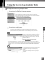
Using the Access Log Analysis Tools .................................... 63
Accessing the Access Log Analysis Tools ................................. 63
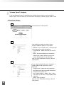
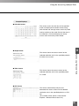
"Access Count" Analysis ........................................................................ 64
"Access Ranking" Analysis .................................................................... 66
"Simultaneous User Count" Analysis ..................................................... 68
"Access Duration" Analysis .................................................................... 70
"Browsing Log File" ................................................................................ 72
"Deleting Cache File" ............................................................................. 73
Chapter 4 Creating a Web Pages
The Sender's Web Page ........................................................ 76
Features of the Java Viewer ....................................................... 77
Features of the Helper Viewer .................................................... 79
Viewing Sample Pages .......................................................... 80
Using the Java Viewer to Send Information ........................... 82
Creating Web Pages that Use Java Viewers .............................. 82
Example of Creating a Web Page that Uses a Java Viewer ...... 84
Displaying text in a Separate Frame Embedded in the Java Viewer ... 84
Using Glimpse and LiveApplet Together ................................................ 86
Using Panorama Snap ........................................................................... 88
Providing LiveApplet without Camera Control ....................................... 90
Changing the Startup Screen and Disconnection Screen .................... 91
Displaying the Host Name and Frame Count in the Video Window ...... 92
Displaying Bitmap Images on the Video Image ..................................... 93
Specifying the Background Color .......................................................... 93
Java Viewer Parameters ............................................................. 94
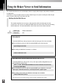
Using the Helper Viewer to Send Information ....................... 98
Setting Up the Web Server .................................................................... 98
Creating wvh files ................................................................................... 99
Example of Creating a Web Page that Uses the Helper
Viewer ....................................................................................... 100
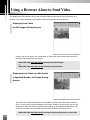
Using the Browser Alone to Send Video ............................. 102
Displaying Live Video as Still Images During Access ........................ 102
Displaying Live Video as a Movie with a Specified Number of
Frames During Access ........................................................................ 102
Displaying Live Video from a Specified Angle as Still Images ........... 103
Chapter 5 Still Image Recording Service
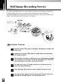
Still Image Recording Service ............................................. 106
Upload Server Features ...................................................................... 106
Setting Up the Still Image Recording Service ..................... 107
Starting "Camera Server Setup" .............................................. 107
Setting and Registering Reservations ................................................ 108
Setting Upload Destinations ................................................................ 114
Setting the Log .................................................................................... 116
Using the Still Image Recording Service to
Send Information ................................................................. 117
Automatically Generated Pages ............................................... 118
When the WWW server function is Used to Send Automatically
Generated Pages ................................................................................ 120
When a Remote Web Server Used to Send Automatically
Generated Pages ................................................................................ 121
Applet Samples ........................................................................ 122
Applet Sample 1: Link List ................................................................... 122
Applet Sample 2: Simple Virtual Movie ............................................... 125
Applet Sample 3: Table List ................................................................. 128
Appendix
Troubleshooting ...................................................................
Error Messages ...................................................................
Index ....................................................................................
Tips ......................................................................................
132
134
150
152
Introduction
Thank you for choosing "WebView Livescope"
This manual describes how to set up and use the
WebView Livescope Camera Server.
Read this manual carefully before you use WebView Livescope to ensure that
you make the best possible use of this product.
Store this manual in a safe place after you finish reading it.
Important
The unauthorized transfer of all or any part of the contents of this manual is forbidden.
The contents of this manual are subject to change without notice.
Every effort has been made to ensure that content of this manual is free from errors.
If you encounter any errors, omissions or apparent inaccuracies, contact the manufacturer.
Notwithstanding above, the manufacturer accepts no liability whatsoever arising from
the results of using this product.
Copyright Information
Under copyright law, video or still images photographed by the client cannot be used for any purpose other than
personal enjoyment without prior permission from the copyright holder
Trademark Information
Microsoft Windows, Windows NT, and Microsoft Internet Explorer are trademarks of the Microsoft Corporation
of the U.S. registered in the U.S. and other countries.
Netscape is a trademark of Netscape Communications Corporation.
All other company or product names used in this document are trademarks or registered trademarks of their
respective holders.
* In this manual, "Microsoft Windows" is abbreviated as simply "Windows".
Conventions
c
Caution
e
Indicates important notes or restrictions that must be observed when using this product. Always
read these notes.
Indicates additional information or explanations for a procedure. You should read these items.
Note
a
Important
4
Indicates a particularly important procedure.
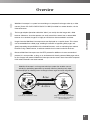
Overview
WebView Livescope is a system for transmitting to a computer live images taken by a video
camera (Canon VC-C4/VC-C4R/VC-C3/VC-C1 MK-II) installed in a remote location, via the
Internet/Intranets.
The image recipient (hereafter called the "client") can easily view the image with a Web
browser. Moreover, since the operator can easily control the camera from a remote Web
browser via a network, images of a highly on-site feel can be transmitted in real-time.
Introduction
Images from the WebView Livescope server are displayed on a special viewer. This viewer
can be embedded into a Web page, enabling the creation of appealing Web pages and
greatly expanding the possibilities of the Internet/Intranets, such as monitoring from remote
locations using a Web browser, to achieve networks that are more useful for business.
Because WebView Livescope uses the HTTP protocol in addition to its own conventional
protocol, it is now possible, as long as an environment for viewing external Web pages exists,
to view images from external WebView Livescope camera servers even from within corporate
LANs where firewalls have been erected.
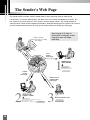
WebView Livescope is an image transmission system that enables users to
actively (by performing operations by oneself) view live (showing now) video
from homepages by allowing users to change camera angle and zoom magnification.
Image Sender
Live
(Homepage creator)
Image Recipient
(User)
Sending the current image
Viewing by switching angle and zoom magnification
Active
Offers an easy way
to provide live information contents.
Offers the advantage of
being able to actively select desirable
parts from live images according to
the user's purposes.
5
Features
■ Easy transmission of live images to the Internet or an Intranet
Uses HTTP protocol in addition to the unique (WebView-TCP) transmission protocol. Image data
can be sent through a firewall without changing network administration settings.
■ Transmission and reception of high-resolution video
WebView Livescope uses the Motion-JPEG image compression system and supports the Osprey100 capture board from ViewCast.com and the Meteor, Meteor II and Meteor/PPB capture boards
from Matrox.
■ Detailed camera control
When the Canon VC-C4 Communication Camera is used, the user can control
the camera angles (pan and tilt) and zoom ratio just as if he or she were actually
behind the camera. It is also possible to set restrictions limiting the camera
angles and zoom ratios that can be used.
■ Four cameras controlled by the same server
WebView Livescope supports up to 4 cameras concurrently.
This gives better image quality and a wider field of view.
■ Communication camera is freely controllable by users receiving live
images.
You can easily control pan/tilt angles, zoom magnification and backlight compensation features of
a remotely installed camera from your computer screen via a network. Camera position can also
be input in advance by using the [Preset] feature. The client can move the camera into the desired
position instantly just by selecting a registered preset.
■ Concurrent video reception by up to 100 users
One server can be used to view video by up to 100 users at a time. The number of concurrent
accesses is set on the camera server to suit the bandwidth of the network being used.
■ Control privileges to prevent contention for camera control
The introduction of control privileges means that contention between multiple clients concurrently
trying to control the camera can be avoided. The default period for which a client has exclusive
control of the camera is 20 seconds. (This can be changed at the server.)
6
■ Support for multiple concurrent image sizes
You can select any of 4 image sizes (640×480, 320×240, 160×120 and 80×60) and transmit them
simultaneously.
■ Enhanced security functions
Video distribution destinations can be restricted using IP addresses.
Introduction
■ Automatic sample page generation function
This function automatically modifies the contents of the sample web page files based on the
camera server settings. The sender can create web pages based on these sample pages. The
wvh files used to start up the helper viewer from the web browser can also be generated
automatically and sent.
■ Panorama image generation function
Version 3.1 of the software features a new function that automatically controls the camera as it
shoots multiple images and then integrates and stores those images as a single panorama image.
The camera angle and zoom ratios in a stored panorama image can be controlled from the viewer
for realistically direct operation. This function also improves the user interface since the panorama
image can be used by the administrator to set the field of view or specify preset positions.
■ Firewall penetration
The helper viewer provides a firewall penetration function previously available only on Java
viewers. This enables video images to be sent regardless of the user's software environment.
■ Automatic shooting, recording and uploading of still images at set intervals
Version 3.1 provides a still image collection function that collects still images shot by the camera
at regular intervals, uploads the collected images to an FTP server and automatically transmits
the images from the web server. Still images shot by the camera according to a preset schedule
can be saved to a local disk on the camera server or uploaded to a specified FTP server.
■ Access log analysis for a quick and clear snapshot of system usage
In version 3.1, the collected access log data is analyzed and the access status displayed as a
graph or table to give a clear and accurate picture of system usage for each user. This picture
shows information such as the number of accesses per day, the periods of heavy usage and the
access time for each individual, and can also be accessed remotely.
7
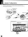
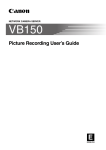
System Configuration
The web server and camera server are connected to the viewer using IP (Internet Protocol).
Normally, the live video is distributed via the internet, but ordinary public phone lines or ISDN lines
can also be used for a direct connection.
Video image sender
Collection of still
images and log data
Camera server
VC-C4
COMMUN
f:4-64mmICATION CAMERA
1:1.4-2.8
VC-C4
COMMUN
f:4-64mmICATION CAMERA
1:1.4-2.8
Camera server settings and
modifications sent
VC-C4
Uploading
Settings su
angle and z
Video and
image data sent
INT
Collection of
still images
E RNET
Web server
(FTP server)
Firewall pe
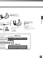
Module configuration
Camera server
WWW interface
cam
HTTP conversion server
Video transmission protocol (TCP)
Camera control protocol (TCP)
Video tra
FTP
Camera
Video server
Upload server
Camera control server
Windows NT4.0
Image capture
PC
VC-C4
COMMUNIC
f:4-64mm ATION CAMERA
1:1.4-2.8
8
Serial port
Network
manager
Camera server settings can be
specified and modified remotely.
Video image receiver
Firewall
penetrated
helper viewer
Java viewer
Web browser
Netscape Navigator or Communicator 4.5 or later or
Internet Explorer 4.01 or later
Live video
Video image receiver
Live video images can be received and
control privileges can be granted allowing
control of the camera.
Web browser
enetrated
HTTP video/
mera control protocol
Introduction
uch as the camera
zoom ratio sent
Remote maintenance
Live still images
Stored still images
Live video & still images Java viewer (web browser)
Web browser (text, video and still images)
Windows95/98/NT
UNIX
Mac OS
Live video
ansmission protocol (TCP)
a control protocol (TCP)
Helper viewer
Web browser (text and video)
Windows95/98/NT
Network
PC
9
Information Sending Side
Web Server
The web server is the computer that runs the web server software. When
accessed from a web browser, this server sends HTML data to the browser.
WebView Livescope Camera Server
This server is made up of a camera and a computer that
is equipped with an image capture board and runs the
VC-C4
COMMUNI
f:4-64mmCATION CAMERA
1:1.4-2.8
camera server software. Normally, the server modules
start up automatically when the computer is switched on.
■ Server Module Types and Functions
Module
10
Functions
Camera control
server
This server receives camera control protocol signals from clients such as the
helper viewer and HTTP conversion server and performs camera control
functions such as pan and tilt. The camera control protocol used is the
WebView-TCP camera control protocol.
Video capture server
This server performs JPEG compression on video signals received from the
camera (VC-C4/VC-C4R/VC-C3/VC-C1 MK-II) via the capture board (Osprey100, Meteor or Meteor-II/PPB) and sends the compressed signals to a client such
as a helper viewer or HTTP conversion server. The protocol used is the dedicated
WebView-TCP video transmission protocol.
HTTP server
This server converts the dedicated WebView-TCP video transmission and
WebView-TCP camera control protocols to the HTTP 1.0-based WebViewHTTP protocol. This module can also operate as a simple web server.
Upload server
This server provides a still image collection function that periodically collects
video data according to a specified schedule and either saves the collected
images to a local disk or uses the FTP protocol to upload the images to a web
server machine connected to the network.
Maintenance server
This server receives communications from the WebView Livescope manager
and modifies settings on the camera server or restarts related services. This
server program can be used to manage the camera server from a remote
location. The communications protocol used is the dedicated WebView-TCP
remote maintenance protocol.
System Configuration
WebView Livescope Manager
The WebView Livescope Manager allows the camera server to be managed
from a remote location.
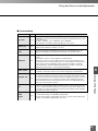
■ Application Types and Functions
Application
Function
The WebView Livescope manager allows each of the camera server modules to
be managed remotely. This application also starts up the administrative viewer
(see below) and the web browser used for access log analysis.
Administrative viewer
This is a helper viewer for the administrator which allows camera control
operations that can only be performed by the camera server administrator and
allows interactive specification of camera presets and restrictions on the field of
view. The administrative viewer can be started up when the WebView
Livescope manager is connected to the camera server. The administrative
viewer also allows the administrator to control the camera during operations
when camera control by ordinary users is forbidden.
Access log analysis
tool
This consists of a CGI program and HTML that analyzes the server access
logs collected on the camera server and then visually presents the viewer
access statistics for the camera server to the administrator. Under the default
settings, HTML pages are downloaded to the client (web browser) by the HTTP
conversion server and the CGI program is also launched by the HTTP
conversion server.
Introduction
WebView Livescope
manager
Information Receiving Side
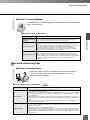
WebView Livescope Viewer
Viewer software is used to view video images sent from the camera
server on a web browser. The two types of viewer software are
described in the table below.
■ Viewer Software Types and Functions
Viewer Software
a
IMPORTANT
Function
Java viewer
The Java viewer allows images from the Camera Server to be viewed on a web browser that
is capable of running Java applets.
Because the Java viewer is downloaded automatically, it does not need to be installed
beforehand like the helper viewer, and it is compatible with any platform capable of running
Java applications.
Where firewalls are installed, this viewer penetrates the firewalls unconditionally since it uses
the HTTP protocol. However, operation may be unstable with some platforms or web browser
types.
Also, because the viewer is downloaded when the web site loads, it starts up and runs more
slowly than the helper viewer.
Helper viewer
This is a helper application launched from a web browser and used to view video images sent
from the camera server.
The helper viewer must be installed beforehand.
Because it does not need to be downloaded. the helper viewer launches more quickly than the
Java viewer. If a viewer will be used frequently, use the helper viewer rather than the Java viewer.
Where firewalls are installed, this viewer penetrates the firewalls unconditionally since it uses the
HTTP protocol.
11
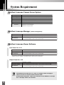
System Requirement
WebView Livescope Camera Server System
Computer
IBM PC/AT compatible (CPU Pentium II, III or better than MMX Pentium 200 MHz)
Operating System
RAM
Network
Video capture board
Windows NT 4.0 (SP5 or later recommended, IE 4.0 or later required)
Supported cameras
VC-C4/VC-C4R/VC-C3/VC-C1 MK-II
Software
Minimum 64 MB recommended
Ethernet (10Base-T or 100Base-T)
Osprey-100, Meteor, Meteor II or Meteor/PPB
WebView Livescope Ver. 3.1 Camera Server software
WebView Livescope Manager
WebView Livescope Viewer
WebView Livescope Manager (remote management)
Computer
Operating System
Web browser
IBM PC/AT compatible
Windows 95/98, Windows NT 4.0 (IE 4.0 or later required) or Windows 2000
Netscape Navigator or Communicator 4.5 or later or
Microsoft Internet Explorer 4.01 or later recommended
WebView Livescope Viewer Software
Java Viewer Ver. 3.10
Computer
Operating System
Web browser
IBM PC/AT compatible
Windows 95/98, Windows NT 4.0 or Windows 2000
Netscape Navigator or Communicator 4.5 or later or
Microsoft Internet Explorer 4.01 or later recommended
* This viewer is automatically downloaded from the camera server at each access.
* Operation may be unstable on operating systems other than those listed above.
Helper Viewer Ver. 3.10
Computer
Operating System
Web browser
IBM PC/AT compatible
Windows 95/98, Windows NT 4.0 (IE 4.0 or later required) or Windows 2000
Netscape Navigator or Communicator 4.5 or later or
Microsoft Internet Explorer 4.01 or later recommended
* This viewer must be installed beforehand.
c
Caution
12
The WebView Livescope Ver. 1.21, 2.01 or 3.0 helper viewer and plug-in
viewer can also be used, but some functions differ.
On Macintosh computers, some of the functions of the WebView Livescope
Ver. 1.20 helper viewer are restricted.
Chapter 1
Installation
This chapter describes how to install and check the operation of the WebView
Livescope camera server, manager and helper software.
Installation Procedure
c
Caution
Before you begin the installation
If there is web server software already installed on the PC to be used for installation,
you must avoid conflicting the port number of WebView Livescope HTTP server and
web server. To ensure that the WebView Livescope HTTP server can penetrate
firewalls, it is installed with a default port number of 80. To ensure that the web
server and HTTP server do not both use port number 80, you should change the web
server port number to a number such as 8080. A precondition of this is that you use
the WWW server function (see P.53).
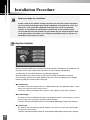
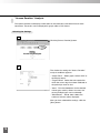
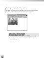
Starting the Installer
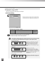
When you load the WebView Livescope Ver. 3.10 Installer CD-ROM into your machine, the
Installer's main screen automatically launches. If it fails to launch, double-click
"wvsetup.exe" on the CD-ROM drive using Windows Explorer.
Click the buttons in the main screen to start up the installer and install the software.
You must log in with the user name (Administrator, etc.) that has Administrator privileges
before installing the servers and the manager.
● Install Servers
This option installs the "WebView Server", "WebView Manager" and "WebView Viewer". These
servers are used to set up the camera server.
* Install this software on Windows NT 4.0 (SP5 or later). (Note) IE 4.0 or later is required.
● Install Manager
This option installs the "WebView Manager" and "WebView Viewer". These programs are used
by the camera server manager to control the server remotely.
* Install this software on Windows 95/98, NT 4.0 or Windows 2000. (Note) IE 4.0 or later is required.
● Install Viewer
This option installs the "WebView Viewer (Helper)". This viewer is used to view video images
sent from the camera server.
* Install this software on Windows 95/98, NT 4.0 or Windows 2000. (Note) IE 3.02 or later is required.
14
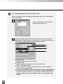
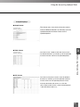
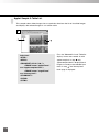
Installing the Server
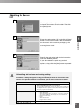
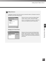
1
Click the [Install Server] button in the main screen
to launch the camera server installer. Then click
the [Next] button.
2
1
Enter the serial number (S/N) and click the [Next]
button. For the serial number, refer to the sticker
Installation
on the outside of the software packaging or the
user registration card.
3
Specify the destination folder for the installation
and click the [Next] button.
If you do not need to specify any particular
options, simply click the [Next] button to proceed.
c
Caution
Uninstalling old versions and reusing settings
If there is an older version of WebView Livescope installed on the machine used for this
installation, a dialog box appears asking you whether you want to uninstall the earlier
version. If the previous software is uninstalled, you can still use the current settings.
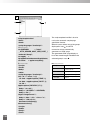
Settings that can be reused
Ver. 3.0
All settings can be reused.
Notes for upgrading from version 3.0 to version 3.10
"Access log" files created with the version 3.0 camera server and still picture
recording files will not be copied to the new destination folder for the installation.
If necessary, copy these files manually.
Ver. 2.0, 2.01
The following settings can be reused:
- Capture Board Type
- Camera information (number of cameras, camera names, video ports,
video formats, COM ports, camera types, field of view restrictions)
- Restriction of client access
- Presets
- WWW server function
- Manager remote connection
Ver. 1.0, 1.10, 1.20, 1.21
None of the settings can be reused.
15
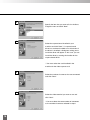
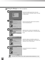
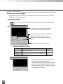
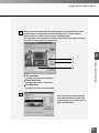
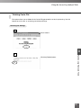
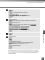
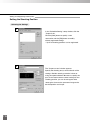
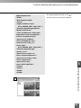
4
Specify the item that you want to list in the Start,
Programs menu and click "Next".
5
Select the capture board installed in your
machine and click "Next". If a capture board
driver has not been installed or an old version of
the driver is installed, a dialog box asking you to
install the driver will appear. In this case, you can
install the driver by starting the installer for the
capture board driver.
* You must select the card installed in the
machine for the video capture card.
6
Select the number of cameras that are connected
and click "Next".
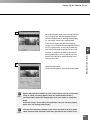
7
Select the video terminal you want to use and
click "Next".
* You must select the same number of connectors
as the number of cameras selected in step 6.
16
Installation Procedure
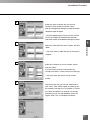
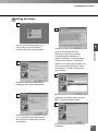
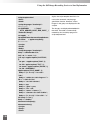
8
Select the type of camera that you want to
connect to each terminal and click "Next".
After this a dialog box for setting the number of cameras
selected in step 6 will appear.
* You must select the type of camera (VC-C4, VC-C4R,
VC-C3, VC-C1 MK-II) connected to each connector.
Look at the camera unit to determine the type of camera.
1
9
Installation
Select the video format for each camera and click
"Next".
* You must select a video format that the camera
supports.
10
Select the COM port to use for camera control
and click "Next".
If VC-C4 cameras have been connected using
cascade connections, see the memo on the next page.
* You must select the port to use for camera
control.
11
Check the items that you set and selected and
click "Next". Files will be copied and settings will
be entered in the registry as installation is carried
out. When installation has finished, a message
prompting you to start the WebView server will
appear. Click "Yes" to complete installation.
17
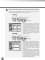
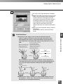
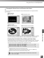
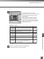
e
Settings for when VC-C4 cameras are connected using cascade connections
Note
If you use cascade connections to connect VC-C4 and VC-C4R cameras, specify the same
COM port for the cameras connected using cascade connections.
Camera server
COM1
VC-C4
VC-C4
Composite connector 1
Composite connector 2
VC-C4
COMMUNI
f:4-64mmCATION CAMERA
1:1.4-2.8
VC-C4
COMMUNI
f:4-64mmCATION CAMERA
1:1.4-2.8
For example, if you connect a VC-C4 camera that
is connected to Composite connector 1 to the COM
1 port of the camera server and then use a
cascade connection to connect it to a VC-C4
camera that is connected to Composite connector
2, specify COM 1 as the COM port for both
cameras. Furthermore, if you use a cascade
connection to connect another camera to the VCC4 camera that is connected to Composite
connector 2, specify COM 1 as the COM port for
this camera as well.
Camera server
COM1
VC-C4
VC-C4
Composite connector 2
Composite connector 1
VC-C4
COMMUNI
f:4-64mmCATION CAMERA
1:1.4-2.8
VC-C4
COMMUNI
f:4-64mmCATION CAMERA
1:1.4-2.8
Next, a dialog box for specifying the order in which
cameras connected using cascade connections
are listed appears. You must arrange the list so
that the cameras are listed in order starting with the
camera closest to the COM port of the camera
server. Click the camera name to select the
camera, and click "Up" or "Down" to change its
order in the list.
For example, if you connect a VC-C4 camera that
is connected to Composite connector 2 to the COM
1 port of the camera server and then use a
cascade connection to connect it to a VC-C4
camera that is connected to Composite connector
1, they should be listed in the order: "VC-C4
connected to Composite connector 2", "VC-C4
connected to Composite connector 1".
18
Installation Procedure
The names of the camera connected to each
COM port and the order in which they are listed
are displayed in the Start Copying Files dialog
box. Check whether the settings are correct.
If you want to change any settings, click "Back" to
return to the Settings screen.
1
Installation
19
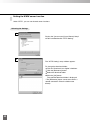
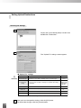
Installing the Manager (for remote management)
1
Click the [Install Manager] button in the main
screen to launch the manager installer. Then click
the [Next] button.
2
Specify the destination folder for the installation
and click the [Next] button.
3
Specify the menu names to be registered in the
[Start] button "Program Menu" and click the [Next]
button.
4
Check the settings and selections made so far
and then click the [Next] button. The installer then
copies files and sets the registries.
5
Click the [Finish] button to complete the
installation.
c
20
Caution
The camera server must be set up in order to perform remote maintenance (➞ P.33).
Installation Procedure
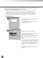
Installing the Viewer
1
2
Click the [Install Viewer] button in the
main screen to launch the viewer
installer. Then click the [Next] button.
1
A dialog box appears asking you to
Installation
agree to the software licensing
agreement. Click the [Yes] button.
If an older version of WebView is
already installed on the machine being
3
used for the installation, a dialog box
appears at this point asking whether you
want to uninstall the old version. After
uninstallation is finished, continue with
the installation.
4
Specify the destination folder for the
installation and click the [Next] button.
5
Specify the menu names to be
registered in the [Start] button "Program
Menu" and click the [Next] button.
6
Check the settings and selections made
so far and then click the [Next] button.
The installer then copies files and sets
the registries.
Click the [Finish] button to complete the
installation.
21
Starting Up and Shutting Down the Camera Server
Starting Up the Camera Server
When you switch on the computer on which the camera server software was installed, the
camera server is automatically launched and the service begins.
Shutting Down the Camera Server
1 Press [Ctrl]+[Alt]+[Delete] and log in as an Administrator.
2 Select [Start]-[Shutdown].
3 Select "Shut down the computer?" and click the [Yes] button.
4 Check that the "It is now safe to turn off your computer." message is displayed and then
switch off your computer.
22
Checking Camera Server Operation
After installation is completed, first check that the camera server is running normally. The simplest
way to check this is by using a sample page.
Checking Procedure
1
Switch on the connected VC-C4 camera and the computer on which the camera
server was installed.
The camera server automatically launches and resets the connected camera. (The
camera automatically returns to the "home" position.)
2
1
From the [Start] menu, select [Programs]-[WebView Livescope]-[Home Page
Installation
3
Press [Ctrl]+[Alt]+[Delete] and log in as an Administrator.
The Windows NT startup screen appears.
Sample].
The WebView Livescope index page appears. Click "To Sample Page".
4
Click "Helper Sample".
If a video image appears, the software is running normally.
23
Notes on Using the Software
This section provides some points to note and items to refer to when you are using WebView
Livescope camera server software.
Connection distance between the camera server and the
camera (VC-C4/VC-C4R/VC-C3/VC-C1 MK-II)
Use a cable no longer than 15 meters, as stipulated in the RS-232C standard. Successful
operation cannot be guaranteed if a cable longer than 15 meters is used. (When using cascade
connections, a cable no longer than 15 meters should be used to connect each camera. Refer
to P.18 for information on cascade connections.)
When a WWW server is running on the same computer as the
camera server
Use the WWW server function.
* For more information on using a proxy web server, refer to "Setting the Web Server Functions"
on P.53.
For subjects not suited to auto focusing, such as night scenes
or objects with no light-dark contrast, set the camera to "Far
Fixed".
* For more information on the auto focus settings, see "Changing the Camera Settings" on P.38.
If the camera server is connected to the internet or an intranet,
1 fixed IP address is always required.
* Dynamic IP addresses using DHCP cannot be assigned.
24
Chapter 2
Camera Server Setting
This chapter describes how to specify the settings for the WebView Livescope
camera server and how to manage the server and monitor its status.
Camera Server Setting
The camera server settings can be specified either on the computer on which the camera server
software was installed (local maintenance) or by from a computer connected to the network (remote
maintenance).
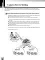
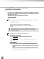
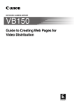
Using the Remote Maintenance Function to Set Up the Camera Server
The WebView Livescope manager can be used to change the camera server settings from a
remote computer connected to the camera server via a network.
● To use the remote maintenance function to set up the camera server, the WebView
Livescope manager program must be installed on the computer connected to the network
(see P.20).
● The computer on which the manager program is installed must be running Windows 95,
Windows 98, Windows NT 4.0 or Windows 2000 with IE 4.0 or later installed (see P.12).
● To use the remote maintenance function, the camera server must first be set up to allow
remote maintenance.*
● Remote maintenance cannot be conducted across a firewall.
* For information on how to set up the camera server, see "Setting the Remote Maintenance
Usage Conditions" on P.33.
Japan
WindowsNT4.0/95/98/2000
with the WebView Livescope
manager installed
INT
Remote
maintenance
U.S.
VC-C4
26
Remote
maintenance
Australia
Camera server
COMMUNICATI
f:4-64mm ON CAMERA
1:1.4-2.8
E RNET
Camera server
VC-C4
COMMUNICATI
f:4-64mm ON CAMERA
1:1.4-2.8
VC-C4
COMMUNICATI
f:4-64mm ON CAMERA
1:1.4-2.8
VC-C4
COMMUNICATI
f:4-64mm ON CAMERA
1:1.4-2.8
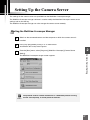
Setting Up the Camera Server
The settings for the camera server are specified from the WebView Livescope manager.
The WebView Livescope manager software is used to modify the WebView Livescope camera server
settings and to view the log.
The WebView Livescope manager can also manage the camera server remotely.
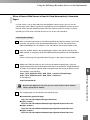
Starting the WebView Livescope Manager
1
Switch on the connected camera and the computer on which the camera server is
installed.
2
Press [Ctrl]+[Alt]+[Delete] and log in as an Administrator.
The Windows NT startup screen appears.
3
From the [Start] menu, select [Programs]-[WebView Livescope]-[Camera Server
Setting].
2
Camera Server Setting
The WebView Livescope manager screen appears.
c
Caution
The protocol used for remote maintenance is a dedicated protocol running
on TCP. Consequently, it cannot penetrate firewalls.
27
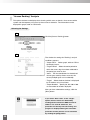
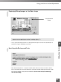
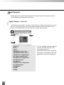
Starting the Administrative Viewer
In the same way as the ordinary users views video, the manager viewer in the camera server
can be used to view the camera video and to adjust the camera presets and video.
The manager viewer can also be used to control the camera when ordinary users are
forbidden to control the camera.
1
Switch on the connected camera and the computer on which the camera server is
installed.
2
Press [Ctrl]+[Alt]+[Delete] and log in as an Administrator.
The Windows NT startup screen appears.
3
From the [Start] menu, select [Programs]-[WebView Livescope]-[Camera Server
Setting].
The WebView Livescope manager screen appears.
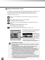
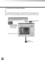
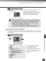
Click the [Administrative Viewer] button.
4
The administrative viewer screen appears.
* Refer to the "Viewer User's Manual" for information on using the viewer.
The manager viewer window is used to display video
and control the camera. Click the [Start Control]
button to be granted control privileges.
If you click the
[Panorama window]
button, a panorama
image is displayed in
a new window. The
camera can be
panned, tilted and zoomed by moving and changing
the shape of the on-screen rectangle.
To display a panorama image, the panorama image
must be photographed and stored (see P.42).
c
Caution
28
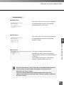
Administrator's Privileges
The administrative viewer has the following special privileges not available
to ordinary viewers:
● The administrative viewer has unlimited video connection time. After
completing the setup, you should quit the manager viewer.
● When the administrative viewer acquires camera control privileges, it
forcibly retains continued camera control even when a request for camera
control privileges is received from an ordinary user. After completing
camera server setup, you must quit the administrative viewer.
Alternatively, you can click the control privileges button in the
administrative viewer again to relinquish control privileges.
● When a view restrictions has been set on the camera server, the
administrative viewer can control the camera beyond the specified field of
view. However, during setup, note that ordinary viewers can also view the
areas outside the specified field of view.
Setting Up the Camera Server
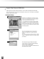
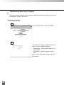
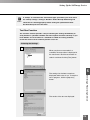
Starting "Camera Server Setting"
In "Camera Server Setting", you can specify a range of camera control settings as well as settings for
the video capture card and logs. However, additional cameras, changes to the video capture card
type and remote maintenance settings can only be specified during local maintenance. These
settings cannot be changed during remote maintenance.
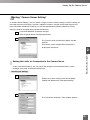
1
Launch the WebView Livescope manager.
Click the [Setup Server Configuration] button.
2
The "[server name] (Local Server) Setup" window
appears.
The current system configuration information is
displayed in tree format.
2
Camera Server Setting
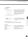
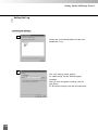
Setting the Limits for Connection to the Camera Server
Under "Connection Setting", you can specify the settings for the connection limits, access
privileges, port setup and remote maintenance.
Selecting the Settings
1
Display the "[server name] (Local Server) Setup"
window and double-click "Connection Setting".
2
The "Connection Limitation" setup window appears.
29
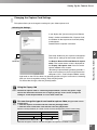
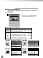
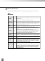
Setting the Limits for Connection to the Camera Server
Setting the connection limits
Selecting the Settings
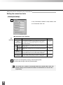
1
In the "Connection Limitation" setup window, click
the "Connection Limit" tab.
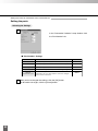
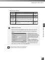
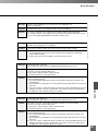
■ "Connection Limit" Settings
a
Item
Details
Default Value
Max
connect Time
Specifies the number of minutes for which video clients can be
connected to the WebView server. When the specified time is
exceeded, the client is automatically disconnected. If "0" is
specified as the connection time, there are no restrictions on
the connection time.
10
HTTPconnect
viewer
Sets the limit on the number of viewers connected using the
WebView-HTTP protocol. The limit can be set to any value between 0
and 100 clients.
10
TCPconnect
viewer
Sets the limit on the number of viewers connected using the
WebView-TCP. The limit can be set to any value between 0 and 100
clients.
10
IMPORTANT
Limit of each
client's connect count
Sets the maximum number of connected video relay modules,
Proxies
such as distribution servers. The limit on the number of video
(distribution servers, etc.)
relay modules can be set to any value between 0 and 20.
Disable camera control
by normal user
2
No check
After you have changed the settings, click the [OK] button.
To discard the changes, click the [Cancel] button.
c
Caution
30
Specifies whether ordinary viewers can control the camera. Putting a
tick in the checkbox prevents ordinary clients from controlling the
5
You cannot set a number of connected clients that exceeds 100 in total. The
default settings for the maximum numbers of connections are 10, 10 and 5
respectively.
Setting Up the Camera Server
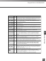
Setting the Limits for Connection to the Camera Server
Setting the client access limitation
Selecting the Settings
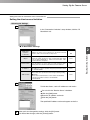
1
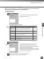
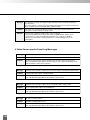
In the "Connection Limitation" setup window, click the "IP
Restriction" tab.
■ "IP Restriction" Settings
Details
Default Value
Applies the same access restrictions to all HTTP-connected
viewers, TCP-connected viewers and proxies.
ON
Object
When the "Apply same restriction to all clients" checkbox is not
ticked, this setting specifies the clients to which limits apply. Limits
can be applied individually to HTTP-connected viewers, TCPconnected viewers and proxies.
None
Restrict clients
Uses IP addresses to set the client access limits applied to clients.
Putting a tick in this checkbox enables limits based on IP addresses.
OFF
IP Address
Sets the IP addresses to which connection is permitted. Up to
20 addresses can be specified. A typical specification format
is "192.168.100.10".
None
Address Mask
Sets the valid bits for IP addresses to which connection is permitted.
Bits for which "0" is specified as the mask are ignored during checking.
■ Example
When a mask of 255.255.255.0 is set for IP address 192.168.100.0,
connection is permitted to addresses 192.168.100.0 to
192.168.100.255.
None
2
Camera Server Setting
Item
Apply same
restriction
to all clients
2
To limit the clients, set the IP addresses and masks.
Put a tick in the "Restrict clients" checkbox.
Click the [Add] button.
Enter the IP address and mask.
Click the [OK] button.
The specified IP address and mask appear on the list.
3
After you have changed the settings, click the [OK] button.
To discard the changes, click the [Cancel] button.
31
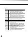
Setting the Limits for Connection to the Camera Server
Setting the ports
Selecting the Settings
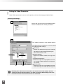
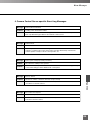
1
In the "Connection Limitation" setup window, click
the "Port Number" tab.
■ "Port Number" Settings
Item
Details
Default Value
Video port
Sets the service port for the WebView-TCP video transmission protocol.
65310
Camera control port
Sets the service port for the WebView-TCP camera control protocol.
65311
HTTP port
Sets the service port for the WebView-HTTP video transmission protocol.
80
Upload port
Port used for running WebView-upload server still image storage tests.
65313
Sets the service port for the WebView-TCP remote
maintenance protocol. Note that this cannot be changed
from a remote connection.
65312
Remote
maintenance port
2
After you have changed the settings, click the [OK] button.
To discard the changes, click the [Cancel] button.
32
Setting Up the Camera Server
Setting the Limits for Connection to the Camera Server
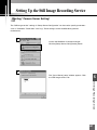
Setting the Remote Maintenance Usage Conditions
Selecting the Settings
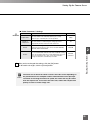
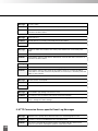
1
In the "Connection Limitation" setup window, click the
"Remote Maintenance" tab.
2
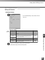
■ "Remote Maintenance" Settings
Item
Details
Default Value
Specifies whether maintenance functions from a remote
computer can be used. If you place a tick in this checkbox,
remote maintenance functions are permitted. When remote
maintenance is permitted, the "Restrict clients" option is
enabled.
OFF
Sets the password used to authenticate the connection when
the "Permit remote maintenance" checkbox is ticked.
None
Restrict clients
Uses IP addresses to set the client access limits applied to the
WebView Livescope manager. Putting a tick in this checkbox
enables client limits to be applied.
OFF
IP Address
Sets the IP addresses to which connection is permitted. Up to
20 addresses can be specified. A typical specification format
is "192.168.100.10".
None
Sets the valid bits for IP addresses to which connection is
permitted. Bits for which "0" is specified as the mask are
ignored during checking.
None
Enable remote
maintenance
Password
Address Mask
Camera Server Setting
a
IMPORTANT
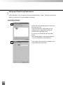
2
a
IMPORTANT
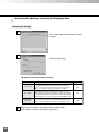
To perform remote maintenance, put a tick in the
"Enable remote maintenance" checkbox and set a
password. This setting then allows camera operations to
be managed from a remote computer.
Adding the "Restrict clients" setting means that remote
maintenance can only be performed from a machine with
one of the specified IP addresses.
3
After you have changed the settings, click the [OK] button.
To discard the changes, click the [Cancel] button.
33
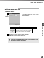
Setting the Video Parameters
Under "Video parameters" you can set the quality and size of the image provided to clients.
Selecting the Settings
1
Display the "[server name] (Local Server) Setup"
window and double-click "Video parameters".
2
The "Video Parameters" setup window appears.
The following icons and buttons are used to specify
the video parameter settings:
Default icon
Denotes that the default image size is selected.
This setting can be changed by clicking the
mouse in the "Default" area.
Enable checkbox
When this checkbox is ticked, the image can be
sent.
[Enable/Disable] button
When the image size is highlighted, this button
can be used to select whether that image size
can be sent.
[Default] button
When the image size is highlighted, this button
resets the image size to the default image size.
e
Note
34
Selecting 640 × 480 increases the load on the camera server and network. Use this
setting for internal LAN connections, etc. Note also that the default image size is the
initial transmission size when the viewer was connected.
Setting Up the Camera Server
■ "Video Parameters" Settings
a
Item
Capture Rate
Quality of
compression
Sets the JPEG compression quality. The quality can be set to
any value between 1 and 99. Higher settings give better
image quality but may reduce the video frame rate.
Default
Sets the default image size specified in the viewer when the
viewer was launched. Four sizes can be selected: 640×480,
320×240, 160×120 and 80×60.
Enable
Sets the image size that can be sent to a client. Four sizes can
be selected: 640×480, 320×240, 160×120 and 80×60. Putting a
tick in the checkbox allows the corresponding image size to be
sent. The Send image size option for the size specified in
"Image size default" is automatically set to ON.
Default Value
3.0fps
30
320×240
2
320×240
and below
Camera Server Setting
3
Details
Sets the image capture rate. The capture rate can be set to
any value between 0.1 and 30 fps (frames per second).
Fractions up to 1 decimal place can be specified.
IMPORTANT
After you have changed the settings, click the [OK] button.
To discard the changes, click the [Cancel] button.
c
Caution
The frame rate at which the viewer receives the video varies depending on
the performance of the computer and the network. Because the principal
restriction is the image transmission speed, the frame rate may be slower
than the capture rate. To increase the frame rate, reduce the compression
quality or select a smaller image size.
35
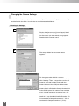
Dynamic Video Parameter Modification
Under "Dynamic change of Video Parameters", you can check and modify the video image
quality while viewing live video without restarting the camera server. The video can be checked
using the administrative viewer.
Selecting the Settings
1
WebView In the WebView Livescope manager
window, click the [Administrative Viewer] button
to start up the administrative viewer.
* If you double-click "Dynamic change of Video
Parameters" first, you cannot click the [Launch
administrative viewer] button. Launch the viewer
first and then click the [Dynamic change of Video
parameters] button.
2
Next, click the [Setup Server Configuration]
button in the WebView Livescope manager
window.
The "[server name] (Local Server) Setup" window
appears. Double-click "Dynamic change of Video
parameters".
3
The "Dynamic change of Video Parameters"
window appears. Change the desired settings
and then click the [Apply] button.
The new settings are applied in realtime and can
be checked on the viewer.
36
Setting Up the Camera Server
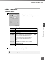
Changing the Capture Card Settings
This option allows you to change the settings for your video capture card.
Selecting the Settings
1
If you display the "[server name] (Local Server)
Setup" window and double-click "Capture Card",
the window for the capture card currently being
used appears.
Double-click the capture card name.
2
2
c
Caution
Camera Server Setting
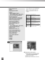
The setup window for your capture card appears.
There are no settings for the current version of
a
the Meteor, Meteor-PPB and Meteor-II capture
IMPORTANT
cards. The screen shown at left is displayed for
the Osprey-100 capture card. You can set the
capture method in this screen.
"Streaming Capture Mode" generally provides a
high frame rate but can place a high load on the
computer's CPU. "Frame Capture Mode" avoids
high loads on the CPU but does not generally provide as high a frame rate as streaming.
After you have changed the settings, click the [OK] button.
To discard the changes, click the [Cancel] button.
Using the Osprey-100
The default capture mode is "Streaming Capture Mode", but this may place a high
load on the CPU when the frame rate is high (eg. 30 fps). In this event, change the
setting to "Frame Capture Mode" or use a lower frame rate.
e
You can change the type of card used to capture video (only possible in local
maintenance).
Note
➀ Click the capture card name and then click the [Change] button.
➁ Click the driver name to be used and then click the [OK] button.
Notation Correspondence (on-screen names and the corresponding correct card names)
On-screen Name
Correct Card Name
Matrox Meteor
Meteor, Meteor/PPB
Matrox Meteor-
Meteor-
ViewCast.com Inc. Osprey-100
Osprey-100
Note that the type of card can only be changed if the capture card driver is installed.
37
Changing the Camera Settings
Under "Camera", you can specify the camera settings, video source settings, panorama settings
and the field of view limits. Use the tabs to switch between the different.
Selecting the Settings
1
Display the "[server name] (Local Server) Setup"
window and double-click "Camera". The screen
for the camera you are currently using appears.
Double-click the camera name.
2
The setup window for the current camera
appears.
To change the order in which cameras
connected using cascade connections are listed,
click "Settings". Then, arrange the list so that the
cameras are listed in order starting with the
camera closest to the COM port of the camera
server. For example, if you connect a VC-C4
camera that is connected to Composite terminal 2
to the COM 1 port of the camera server and then
use a cascade connection to connect it to a VCC4 camera that is connected to Composite
terminal 1, they should be listed in the order: "VCC4 connected to Composite terminal 2", "VC-C4
connected to Composite terminal 1" (P.18) .
38
Setting Up the Camera Server
Changing the Camera Settings
Changing "Camera setting"
Selecting the Settings
1
Display the setup window for the current camera
and click the "Camera setting" tab.
2
Item
Camera Name
COM port address
Wide convertor
Power Off time
Power On time
Shutter speed
Focus
2
Details
Sets the name of the camera being used.
Sets the serial port to which the camera is connected.
Specifies whether a wide-angle lens is used on the current
camera. A tick in the checkbox indicates that a wide-angle
lens is being used.
Sets the time at which the camera is switched off. Because
the auto-focusing may fail to work effectively if the camera is
used for an extended period, the camera must be switched off
at least once a day. Enter a time in the <hour>:<minute>
format.
Sets the time at which the camera is switched on. Because
the autofocusing may fail to work effectively if the camera is
used for an extended period, the camera must be switched off
at least once a day. Enter a time in the <hour>:<minute>
format.
Sets the camera shutter speed.
■ VC-C3: Either Auto (1/60) or Auto (1/100) can be selected.
■ VC-C1 MK-II, VC-C4, VC-C4R:Either Auto, 1/60 or 1/100 can
be selected.
■ NTSC: For PAL-version cameras, 1/60 is changed to 1/50 and
1/100 is changed to 1/120.
Placing a tick in the "Far Fixed" checkbox switches off the
camera's autofocus feature and fixes the focus at infinity.
Camera Server Setting
■ "Camera setting" settings
Default Value
Camera number
COM1
None
03:00
03:01
Auto
Autofocus
After you have changed the settings, click the [OK] button.
To discard the changes, click the [Cancel] button.
c
Caution
The Focus setting only functions on the VC-C3 and is not available on the
VC-C1.
39
Changing the Camera Settings
Changing the image source
You can set the type of video input port and signal.
Selecting the Settings
1
Display the setup screen for the camera being
used and click the "Video Source Setting" tab.
■ "Video Source Setting" settings
Item
2
Details
Capture Channel
Sets the video input port
Capture Format
Sets the type of video signal
Default Value
Composite1
NTSC
After you have changed the settings, click the [OK] button.
To discard the changes, click the [Cancel] button.
c
Caution
The number of video input ports and the ports that can be used concurrently
for multiple input differ depending on the type of video capture board.
● Meteor,Meteor/PPB
Composite 1 and S-Video can be used.
Optional cables can be used to add 4
more ports (Composite 2-5). However,
Expansion port
Composite 1 and 2 cannot be used
S-Video Composite1
concurrently, nor can Composite 4 and SThe expansion port cables and colors are Composite 2 (red),
Composite 3 (green), Composite 4 (blue) and Composite 5 (black). Video.
● Meteor-II
Expansion port
Composite1
The expansion port cables and colors are Composite 2 (red),
Composite 3 (green), Composite 4 (blue), Composite 5 (black),
S-Video 1 (red/green) and S-Video 2 (blue/black)
Composite 1 can be used.
Optional cables can be used to add 6
more ports (Composite 2-5 and S-Video 12). However, Composite 1 and 2 cannot be
used concurrently, nor can S-Video 1 and
Composite 1-3 or S-Video 2 and
Composite 4-5.
● Osprey-100
Composite 1-3 and S-Video can be used.
Some models do not have a Composite 3
port.
S-Video Composite3 Composite2 Composite1
40
Setting Up the Camera Server
e
Adding Cameras
Note
In WebView Livescope, one camera server can control 4 cameras. (Changes can only be
specified as part of local maintenance.)
Display the "[server name] (Local Server) Setup"
window, select "Camera" and click the [Add]
button. In the dialog box that appears, specify the
camera to be added and click the [OK] button.
2
Camera Server Setting
Changing the Camera Used
Display the "[server name] (Local Server) Setup"
window, select "Camera" and click the [Change]
button. In the dialog box that appears, specify the
camera to which you want to change and click the
[OK] button.
41
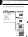
Changing the Camera Settings
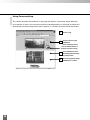
Selecting Panorama Images
The procedure below describes how to photograph a panorama image and how to specify the
settings for panorama photography.
Selecting the Settings
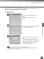
1
Display the setup screen for the camera being used and click the "Panorama Setting"
tab.
a
IMPORTANT
Displays the currently registered panorama
image (blank if no image is registered).
Shows the date and time when the currently
registered panorama image was shot.
Erases the currently registered panorama
image.
Photographs a new panorama image.
■ "Panorama Setting" settings
Item
Back light adjust
Position of AE Lock
(VC-C4/VC-C4R
/VC-C3)
Details
Specifies whether backlight compensation is on or off when
images are photographed.
Specifies whether the AE lock position when images are
photographed is in the middle of the panorama image or in the
initial camera position.
Default Value
Off
Center of the
panorama image
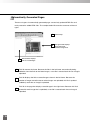
2
Set the photography parameters and click the
[Capture] button to take the picture.
The camera automatically photographs the entire
field of view divided into 40 segments (VC-C4),
65 segments (VC-C4R), 21 segments (VC-C3) or
15 segments (VC-C1 MK-II).
42
Setting Up the Camera Server
3
When photography ends, click the [OK] button if
you are happy with the photographed images.
Click the [Stop] button to interrupt photography.
To start again, click the [Try again] button.
If you are not happy with the photographed
images, you can repeat the procedure by clicking
the [Try again] button. If you want to redo only
one of the photographed images because, for
2
Camera Server Setting
instance, a subject in the field of view moved
during photography, you can reshoot just that
portion of the image by double-clicking in the
frame for that shot.
4
Click the [OK] button.
To discard the settings, click the [Cancel] button.
c
Caution
c
Caution
Specify the panorama settings for each of the cameras used. If no panorama
image is stored, a warning appears when the administrative viewer is
launched and the panorama image display area in the viewer is completely
black.
Panorama images should always be specified as they are extremely helpful
when users are viewing video images.
The size of the panorama window on the viewer may differ from that shown
above if field of view restrictions have been specified on the camera server.
43
Changing the Camera Settings
Setting limits for the field of view
The field of view can be specified by setting limits on the camera pan, tilt and zoom ratio
(angle of view).
Selecting the Settings
1
Display the setup screen for the camera being
used and click the "View Restriction" tab.
■Visibility Range Limitation Settings
Item
Visibility range
limitation On
Pan
Tilt
Zoom ratio
(Field of view)
Explanation
Default Setting
Specify whether or not to limit the camera's visibility range.
You can limit the camera's visibility range by checking the
checkbox. However even if you do not limit the camera's
visibility range, the visibility range will be limited because
the camera's movement range is restricted.
You can restrict the angles to which the camera can pan left and right.
The angles to which camera movement is restricted vary depending
on whether or not the wide-angle lens is being used.
You can restrict the angles to which the camera can tilt up and down.
The angles to which camera movement is restricted vary depending
on whether or not the wide-angle lens is being used.
You can restrict the zoom field and the wide-angle field.
The extent to which these fields can be restricted varies depending
on whether or not the wide-angle lens is being used.
OFF
Controllable range
for each camera
Controllable range
for each camera
Controllable range
for each camera
■Video Capture Range for Each Camera (approximate values)
VC-C4
Controllable range
Angle
-100° to 100°
Tilt control range
-30° to 90°
3.7° to 47°
Zoom control range
(with wide converter) (4.6° to 61°)
Horizontal shooting range -124° to 124°
(with wide converter) (-131° to 131°)
Pan control range
VC-C4R
Controllable range
Angle
Pan control range
Tilt control range
-170° to 170°
-90° to 10°
Zoom control range
3.7° to 47°
Horizontal shooting range -180° to 180°
Vertical shooting range
-108° to 28°
Controllable range
Angle
Vertical shooting range -48° to 108°
(with wide converter) (-53° to 113°)
VC-C3
Controllable range
Angle
Pan control range
-90° to 90°
-30° to 25°
4.8° to 48°
(6.7° to 67°)
Horizontal shooting range -114° to 114°
(with wide converter) (-124° to 124°)
-50° to 50°
Tilt control range
-20° to 20°
Zoom control range
6.1° to 46°
(with wide converter) (8.2° to 61°)
Horizontal shooting range -73° to 73°
(with wide converter) (-81° to 81°)
Vertical shooting range -48° to 43°
(with wide converter) (-55° to 50°)
Vertical shooting range -37° to 37°
(with wide converter) (-45° to 45°)
Tilt control range
Zoom control range
(with wide converter)
44
VC-C1
MK-II
Pan control range
Setting Up the Camera Server
2
Put a tick in the "View Restriction" checkbox.
Specify the angle of view limits for pan, tilt and
zoom. You can set these values by entering
numbers directly or by dragging the white
rectangular frame on the panorama image to
the desired position and shape. The green
frame indicates the limits of the telephoto
zoom angle of view and the red frame
indicates the limits of the wide-angle angle of
view.
After you have changed the settings, click the
[OK] button.
To discard the settings, click the [Cancel]
button.
2
When you set limits on the
field of view, the range of
camera movement is
automatically restricted.
Camera Server Setting
● The limits on the angles of pan and tilt are imposed not by the
camera's range of movement, but by the angle of the field of view.
Consequently, the camera's range of movement narrows when the
wide-angle limits in the zoom ratio (angle of view) adjustment are set
wide.
When wide-angle is selected,
the field of view will be
exceeded if the camera's
range of movement remains
unchanged. Accordingly, the
range of movement is
automatically reduced.
Restricted field of view
Range of camera movement
RA
ME . 8
N CA - 2
TIO 1 . 4
ICA 1 :
UN m
MM 4 m
CO 4 - 6
f:
Camera
Area photographed.
Also, if the field of view for left pan is reduced, camera movement is
restricted to prevent the area to the left from being photographed and,
as a result, the camera direction automatically shifts to the right of
center.
Photographed image
Restricted field of view
COMMU
NICATIO
f:4-64
N
m m 1 CAMERA
:1.4-2
.8
COMMUNICATION CAMERA
f:4-64mm 1:1.4-2.8
COMMUNICATION CAMERA
f:4-64mm 1:1.4-2.8
Note
View Restrictions
RA
ME . 8
N CA - 2
TIO 1 . 4
ICA 1 :
UN m
MM 4 m
CO 4 - 6
f:
e
Zoom out
(to wide-angle)
Automatically
pans right.
● When the pan range is narrows, the range of zoom settings may also
be reduced as a result. This is because the view restrictions for pan,
tilt and zoom are controlled automatically.
45
Changing the Camera Control Settings
Use the procedure below to set the camera control privileges and preset positions.
Selecting the Settings
1
Display the "[server name] (Local Server) Setup"
window and double-click "Camera Control
Setting".
2
The "Camera Control" setup window appears.
46
Setting Up the Camera Server
Changing the Camera Control Settings
Setting the Camera Control Time
Selecting the Settings
1
In the "Camera Control" setup window, click the
a
"Camera Control" tab.
IMPORTANT
2
Item
2
Details
Camera Server Setting
■ "Camera Control" settings
Default Value
Camera Control
Queue Length
Sets the number of people who hold the camera control
privileges granted when clients control the camera. This
parameter can be set to any number between 0 and 20.
5
Camera Control
Time
Sets the time for which a client who has been granted control
privileges has exclusive access to the camera. The exclusive
control time can be set to any value between 0 and 3600
seconds.
20
After you have changed the settings, click the [OK] button.
To discard the settings, click the [Cancel] button.
e
Note
If the camera is controlled via the internet, the exclusive control time should
be lengthened somewhat (eg. 40 seconds).
47
Changing the Camera Control Settings
Setting Camera Display Positions (Preset Positions)
Camera positions can be specified and stored in a catalog format. Simply by selecting the
specified preset position data, a client can view the video image intended by the sender.
Because any name can be assigned to a preset position, you can name and store a preset
position in a way that clearly identifies the particular angle you want to show to the client.
Selecting the Settings
1
In the "Camera Control" setup window, click the
"Preset View" tab.
When you click the [Add] button, the "Preset
(Add)" window appears.
2
Enter the name of the preset position.
In the Camera field, select the camera (when 2
cameras or more are connected).
When 2 cameras or more are to be used, you can
enter and set the preset name for each of the
cameras.
Set the camera angles and zoom settings. You
can set these values by entering numbers directly
or by dragging the white rectangular frame on the
panorama image to the desired position and
shape.
After you have changed the settings, click the
[OK] button.
48
Setting Up the Camera Server
3
The preset data appears on the list.
You can reorder the presets using the [Up] and
[Down] buttons. Up to 10 preset positions can be
stored at one time.
2
To set the home position
Camera Server Setting
e
Note
Use the procedure below to set the position to which the camera moves
when nobody holds camera control privileges.
In the "Camera Control" setup window,
click the "Preset View" tab.
Click the name of the preset position
you want to select as the home
position.
Click the [Set Home] button.
Preset selected as "Home".
49
e
To set a preset position while viewing the video
Note
You can launch the viewer and specify preset position while you are watching the
actual video image.
1
In the "Camera Control" setup window,
click the "Preset View" tab.
2
When you double-click the name of the preset you want to set or click the
[Edit] button, a window appears in which you can set the camera position and
zoom settings using either the panorama image or numbers.
Preset name
Use this field to change the preset name.
Camera name
Select the camera for which the preset is to be specified.
"Pan", "Tilt" and "Zoom"
Type in numbers or use the up and down arrows to set the respective
settings for the preset position.
You can also specify the preset settings visually by dragging the
white rectangular frame on the panorama image to the desired
position and size. You can drag the frame to any position and
shape.
50
Setting Up the Camera Server
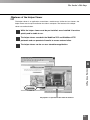
3
When you click the [Adminstrative Viewer] button, the administrative viewer
window appears. The position and zoom settings of the camera used for
monitoring by the viewer can be used as a preset position.
Click the [Start Control] button to acquire camera control privileges and move
the camera to the position you want to set.
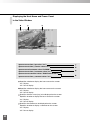
2
Camera Server Setting
Tilt scroll bar
Changes the camera tilt (up/down).
Zoom scroll bar
Changes the camera's zoom ratio.
Pan scroll bar
Changes the camera pan (left/right).
4
Click the [Current Position] button.
The specified camera position and
zoom settings are automatically set.
Click the [OK] button.
51
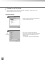
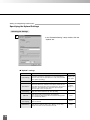
Setting the WWW server function
Under "HTTP", you can set the web server functions.
Selecting the Settings
1
Display the "[server name] (Local Server) Setup"
window and double-click "HTTP Setting".
2
The "HTTP Setting" setup window appears.
To change the download folder:
Tick the "Download Java Applet" checkbox.
Click the [Reference] button.
Select the download folder.
Click the [OK] button.
The specified download folder is displayed.
* The [Reference] button cannot be used via a
remote connection. Enter the folder name
directly.
52
Setting Up the Camera Server
■ "HTTP Setup" Settings
Item
Default Value
Use WWW
Server
Details
Specifies whether to use the proxy web server function. The
proxy web server functions can be used when this checkbox is
ticked.
Host Name
Sets the name of the web server host used as the proxy web server.
localhost
Port Number
Sets the port number for the web server host used as the proxy web server.
8080
Download
Java Applet
Specifies whether the Java viewer and sample pages are
downloaded from the HTTP conversion server. If you place a
tick in the checkbox, the Java viewer can be downloaded. If the
checkbox is not ticked, the Java viewer cannot be supplied to
the client.
ON
Download Root
Sets the directory path used to store Java applets, etc. This
folder stores the Java viewer and other original Java applets
and sample pages.
<WebView
installation
path\Download
Root>*
OFF
2
* The default is C:\Program Files\Canon\WebView\DownloadRoot
Camera Server Setting
e
WWW Server Function
Note
When you want to run the WebView Livescope camera server and web
server on the same computer, set up the web server as a <proxy web
server>.
Setting the web server as a
<proxy web server> allows the
web server functions to be used
from the WebView-HTTP video
protocol service port (default:
80).
Tick the "Use WWW Server"
checkbox, enter the web server
host name in the "Host name"
field, and set the web server
port number to a number other than 80 (8080, etc.).
3
Change the settings and then click the [OK] button.
To discard the settings, click the [Cancel] button.
53
Changing the Log File Settings
Use the procedure below to collect the "TCP video", HTTP video", "Camera control" and
"Remote maintenance server" access logs.
Selecting the Settings
1
Display the "[server name] (Local Server) Setup"
window and double-click "Log".
2
The "Access Log" setup window appears.
a
IMPORTANT
Place a tick in the access logs to be collected and
specify the access log storage location in the
"Directory" field.
* The "Directory" cannot be specified remotely.
54
Setting Up the Camera Server
■ "Log" Settings
Item
TCP Protocol
Details
Specifies whether the TCP video server log is collected. When
this checkbox is ticked, the log can be collected. If you collect
the log, you must specify the access log storage location.
Default Value
ON
HTTP Protocol
Specifies whether the HTTP video server log is collected.
When this checkbox is ticked, the log can be collected. If you
collect the log, you must specify the access log storage
location.
ON
Camera control
Specifies whether the camera control server log is collected.
When this checkbox is ticked, the log can be collected. If you
collect the log, you must specify the access log storage
location.
ON
Remote
Maintenance
Specifies whether the remote maintenance server log is
collected. When this checkbox is ticked, the log can be collected.
If you collect the log, you must specify the access log storage
location. However, the remote maintenance log cannot be
changed via a remote connection.
ON
Specifies the folder created for the log files.
Camera Server Setting
Directory
2
<WebView
installation
path\log>*
* The default path is C:\Program Files\Canon\WebView\Sys\log
3
a
IMPORTANT
Click the "Log analysis" tab. In this tab, you can
change the authentication setting for the access
log analysis tool (see P.63).
Tick the "Enable access from browser" checkbox
and set the password. This allows the access log
analysis URL (http://192.168.100.10*/-wvdoc-01-/
As) to be accessed directly from the browser and
access log analysis to be performed.
* Example When the camera server IP address
is set to 192.168.100.10.
4
After you have changed the settings, click the [OK] button.
To discard the settings, click the [Cancel] button.
55
Viewing the Event Log
Use the procedure below to view the event log of the computer running the camera server.
Viewing this log shows you the status of the computer running the camera server.
Selecting the Settings
1
Select [Start]-[Programs]-[WebView Livescope]-[Camera server setting]. The WebView
Livescope manager window appears.
Click the [View Event Log] button.
2
The "Server Event Log display" window appears.
Click the "Event log" menu and select the event
log you want to view.
3
The selected event log is displayed.
e
Displaying Event Logs
Note
Each event log screen shows 20 records.
If the log contains more than 20 records, you can view other screens by
clicking the [Previous 20 lines] or [Next 20 lines] button.
To view the most recent event log, click the [Recent] button.
56
Setting Up the Camera Server
Viewing the Video Frame Rate
Use the procedure below to view the frame rate for video received by connected clients. You
can select and view the WebView-HTTP protocol (Java viewer and helper viewer) or
WebView-TCP protocol (helper viewer).
Selecting the Settings
Select [Start]-[Programs]-[WebView Livescope]-[Camera Server Setting]. The
WebView Livescope manager window appears.
1
Click the [View Video Frame Rate] button.
2
2
The "Video Capture Rate monitor" window
Camera Server Setting
appears. Select the viewer to be displayed from
the View menu.
3
The video display status for the select viewer is
displayed.
The displayed data is as follows:
● Date of monitoring
● Number of connected clients
● Connected client name: Image size: Quality:
Frame rate
e
Updating the displayed information
Note
Clicking the [Recent] button updates the displayed information to reflect the
most recent status.
57
Automatically Updating or Saving the Displayed Data
Selecting the Settings
1
The "Video Capture Rate Monitor" window
appears.
2
Select [File]-[Config].
■ "Setup Frame rate monitor" settings
3
Item
Details
Save to File
Saves the displayed frame rate to a file. When this checkbox is
ticked, the displayed frame rate can be saved to a file. If the
Save to file option is selected, the [Begin save] and [End save]
buttons in the "Frame rate monitor" window are enabled.
Auto Update
Automatically updates the displayed frame rate to reflect the
latest information. When this checkbox is ticked, the frame rate
is automatically updated to the latest information. The updating
interval can be set to any value between 10 and 3600 seconds.
OFF
Display DNS
Hostname
Changes the list of clients from IP addresses to DNS hosts.
However, some hosts may not be displayed if the DNS settings
are incorrect. This display format may also require more time.
OFF
After you have changed the settings, click the [OK] button.
To discard the settings, click the [Cancel] button.
58
Default Value
OFF
Setting Up the Camera Server
Automatically Updating or Saving the Displayed Data
Saving the Frame Rate Monitor Details to a File
Selecting the Settings
1
The "Video Capture Rate Monitor" window
appears.
Click "View" and select the viewer to be
displayed.
2
2
Camera Server Setting
The video display status for the selected viewer is
displayed. Select [File]-[Config].
3
Tick the "Save to file" checkbox and specify a file
name.
If you select "Auto update", the frame rate is
saved to the file at set intervals. If "Auto update"
is not selected, the frame rate is saved to the file
each time you click "Recent" in the "Video
Capture Rate Monitor" window.
4
Click the [OK] button and then click the [Save Start] button.
From that point, the monitor data is saved to the file. Filing ends when you click the
[Save End] button or [Close] button.
59
Setting Up the Camera Server
60
Chapter 3
Access Log Analysis Tools
This chapter describes how to set up and view the access log analysis
tools that are used to analyze how users utilize the information
distributed using WebView Livescope.
Access Log Analysis Tools
The access log analysis tools analyze the access log data stored by the camera server and then
show the statistics for past viewer access to the camera server in the form of graphs or tables.
The administrator can use these tools to quickly and easily ascertain the user access status.
Access log analysis can be viewed not only from the camera server machine and other
machines Livescope manager is installed, but also from password-protected web browsers. This
enables the administrator to obtain access statistics in a wide range of situations.
camera server
VC-C4
VC-C4
COMMUNICATIO
f:4-64mm N CAMERA
1:1.4-2.8
Access
log
collection
COMMUNICATIO
f:4-64mm N CAMERA
1:1.4-2.8
Access
log
analysis
INT
E RNET
View
the access log
View
the access log
Penetrate
firewalls
Access from
the WebView Livescope manager
c
Caution
or
Access from
a web browser
● To analyze the access logs, the camera server must first be set up to collect the
access logs. See P.54 for setup information.
● The web browsers listed below that run JavaScript and Java must be installed on
the machine used to view the analysis results.
Recommended browsers:
Netscape Navigator or Communicator 4.5 or later
Internet Explorer 4.01 or later
● To access the logs directly from a web browser, you must first set the permission
and a password on the camera server. See P.55 for setup information.
62
Using the Access Log Analysis Tools
Accessing the Access Log Analysis Tools
Access from the WebView Livescope manager
From the WebView Livescope manager window, click the [View
Access Statistics] button. The web browser starts up and the page for
viewing the access log analysis appears.
Access from a web browser
3
Access Log Analysis Tools
Log access from the WebView Livescope manager described above cannot
penetrate firewalls. To penetrate firewalls, use the following access procedure.
1
Launch the web browser and type in the URL of
the camera server with the access log analysis
tools installed to access the analysis. The URL
should look like this:
http://192.168.100.10*/-wvdoc-01-/As
* The underscored portion is a sample IP address. Enter the actual camera server IP address.
Also, if the camera server's HTTP server port number is 80, only the camera server host name is
required.If not, you must include the camera server host port number (eg. 192.168.100.10:
8080).
2
In the displayed page, enter the password set in
the WebView manager and click the [OK]
button.
The page for viewing the access log analysis
appears.
63
"Access Count" Analysis
In the specified period, data is collected on the number of times clients have accessed the
camera server. You can select any of 4 formats for data display: calendar, graph, table or CSV.
Selecting the Settings
1
Click the [Access Count] button.
2
The window for setting the "Access count"
analysis conditions appears. If you select
"Calendar" as the "Output Form", a setup window
of the type shown at left is displayed.
- "Target Month" Select the month you want to
view.
- "Items" Tick the checkboxes for the desired
viewer types used by clients to access the
server (multiple types can be selected).
After you have selected the settings, click the
[Start] button.
3
If you select an option other than "Calendar", a
setup window of the type shown at left is
displayed.
- "Target Period" Select the entire period for
which the access logs have been collected or
the period you want to view.
- "Unit" Select "Month", "Week", "Day", "Hour",
"Per week" or "Per hour" as the period for data
tabulation.
- "Items" As for [2] above.
After you have selected the settings, click the
[Start] button.
64
Using the Access Log Analysis Tools
Sample Displays
● Calendar format
The access counts for each day in the specified
month are displayed in calendar format, along
with the total and average access counts by week
and by each day of the week. Each of the days in
the calendar is a link and displays the hourly
access count for that day when clicked.
3
● Graph format
Access Log Analysis Tools
This format shows the access counts for the
selected tabulation units in the specified period in
the form of a bar chart.
● Table format
This format shows the access counts for the
selected tabulation units in the specified period
as a table.
● CSV format
This format automatically analyzes and
downloads the access counts for the selected
tabulation units in the specified period as a CSV
file.
(The sample screen shown is from Internet
Explorer + Microsoft Excel. See P.74.)
65
"Access Ranking" Analysis
This option tabulates and displays data showing which users or domains have accessed the
system and the frequency of access by those users or domains. The information can be
displayed in graph, table or CSV format.
Selecting the Settings
1
Click the [Access Ranking] button.
2
The window for setting the "Ranking" analysis
conditions appears.
- "Output Form" Select graph, table or CSV as
the display format.
- "Target Period" Select the entire period for
which the access logs have been collected or
the period you want to view.
- "Items" Tick the checkboxes for the desired
viewer types used by clients to access the
server (multiple types can be selected).
- "Target" Select whether the data is displayed
by IP Address or by Host Name.
- "Output Number" Specify 20, 50, 100 or 200
as the number of records displayed.
After you have selected the settings, click the
[Start] button.
e
Note
66
If you select "Host name" as the "Target"
option, the host names are obtained by
working back to extract the DNS from the IP
address. For some IP addresses, this
procedure can be very time-consuming. The
progress is displayed during this extraction
procedure and the process can be cancelled
by clicking the [Stop] button.
Using the Access Log Analysis Tools
Sample Displays
● Graph format
This format shows the access count ranking for
the selected output records in the specified
period in the form of a bar chart.
● Table format
This format shows the access count ranking for
the selected output records in the specified
3
period as a table.
Access Log Analysis Tools
● CSV format
This format analyzes and automatically
downloads the access count ranking for the
selected output records in the specified period as
a CSV file.
(The sample screen shown is from Internet
Explorer + Microsoft Excel. See P.74.)
c
Caution
For users connected via a proxy server who use the WebView-HTTP protocol
(the Java viewer or helper viewer), the IP address of the proxy host is
displayed in the access ranking.
For users using the WebView-TCP protocol (helper viewer only), the IP
address of the machine on which the viewer is directly running is displayed in
the access ranking.
67
"Simultaneous User Count" Analysis
This option tabulates and displays the number of clients connected concurrently. This data can
be displayed in graph or CSV format.
Selecting the Settings
1
Click the [Simultaneous User Count] button.
2
The window for setting the "Simultaneous User
Count" analysis conditions appears.
- "Output Form" Select graph or CSV as the
display format.
- "Target Date" Select the date you want to
view.
After you have selected the settings, click the
[Start] button.
68
Using the Access Log Analysis Tools
Sample Displays
● Graph format
This format shows the hourly shifts in the number
of concurrent connections for the specified date.
The upper chart shows the number of concurrent
connections for HTTP clients (Java viewers or
helper viewers connected via HTTP), and the
lower chart shows the number of concurrent
connections for TCP clients (helper viewers
connected via TCP).
3
Access Log Analysis Tools
You can use the selection box below the graphs to
change the display settings along the time axis. You
can also select any of the following 3 levels for the
time axis display.
outline: Shows 1 day (24 hours).
normal: Shows roughly 3 hours. The scroll bar can be used to shift the time axis.
Detail: Shows roughly 1 hour. The scroll bar can be used to shift the time axis.
● CSV format
This format analyzes the hourly shifts in the
number of concurrent connections for the
specified date and automatically downloads the
analysis as a CSV file.
(The sample screen shown is from Internet
Explorer + Microsoft Excel. See P.74.)
69
"Access Duration" Analysis
This option tabulates and displays information on the continuous connection time for each
connection. The results can be displayed in graph, table or CSV format.
Selecting the Settings
1
Click the [Access Duration] button.
2
The window for setting the "Access Duration"
analysis conditions appears.
- "Output Form" Select graph, table or CSV as
the display format.
- "Target Period" Select the entire period for
which the access logs have been collected or
the period you want to view.
- "Items" Tick the checkboxes for the desired
viewer types used by clients to access the
server (multiple types can be selected).
- "Max Minutes" Set 20, 50 or 100 as the
number of minutes (time) displayed.
After you have selected the settings, click the
[Start] button.
70
Using the Access Log Analysis Tools
Sample Displays
● Graph format
This format uses a bar chart to show the access
count for different durations (in minutes) up to the
specified maximum minutes shown for the
specified period.
● Table format
3
Access Log Analysis Tools
This format uses a table to show the access count
for different durations (in minutes) up to the specified
maximum minutes shown for the specified period.
● CSV format
This format analyzes the access count for different
durations (in minutes) up to the specified maximum
minutes shown for the specified period and automatically downloads the results as a CSV file.
(The sample screen shown is from Internet Explorer
+ Microsoft Excel. See P.74.)
71
"Browsing Log File"
This option allows you to view the error log and the execution progress of the still image
recording function (upload server). You can also use this option to view the access logs for the
servers.
Selecting the Settings
1
Click "Browsing Log File".
2
The window for setting the "Browsing Log File"
conditions appears.
- "Log Type" Select upload, TCP video, HTTP
video, camera control or remote maintenance.
- "Target Date" Select the date you want to view.
When you have selected the settings, click the
[Get Log] button.
Sample Display
The log files are all displayed in the format shown below.
Log file name and period for which the
log has existed
Date of the log displayed
Links to the logs on the dates
immediately before and after the log
displayed
Number of data records displayed
from the log data for the selected date
Link to data for the selected date that
is not displayed
Log file
72
Using the Access Log Analysis Tools
"Deleting Cache File"
This option allows you to delete all the Cache File generated for analysis processing. Use this
feature for tasks such as analyzing past backup file logs.
Selecting the Settings
1
Click "Others".
3
Access Log Analysis Tools
2
Click the [Delete] button.
73
Using the Access Log Analysis Tools
c
Caution
c
If you select "Print" in the Netscape browser, graphs sometimes may not be
printed as they appear on the screen. In Internet Explorer also, the "Number of
Concurrent Connections" graphs other than "outline" may not be printed as they
appear on the screen.
If you select the CSV format, the operation procedure and display differs
depending on the web browser and the installed applications.
Caution
Using the Netscape browser
A dialog box for saving the CSV file to a local disk appears, allowing you to select
the save location and save the file. The analysis results are not displayed on the
access log analysis page.
Using Internet Explorer on a machine with Microsoft Excel installed
The browser launches Microsoft Excel and the CSV file written by Excel appears
in the browser page. You can save the CSV file by selecting "Save As..." in the
"File" menu.
Using Internet Explorer on a machine without Microsoft Excel
installed
The CSV file is displayed as text in the browser window. To save the CSV file,
first click the right mouse button in the frame in the browser window that
contains the CSV data. Select "View Source" from the pop-up menu that appears
and then select "Save As..." from the "File" menu in the View Source window to
save the CSV file.
74
Chapter 4
Creating Web Pages
This chapter describes how to use WebView Livescope to transmit
information. Video can be transmitted in a number of ways, including
displaying video or still images on a web page and displaying multiple images.
The Sender's Web Page
The sender with the camera server installed builds a web page to be used for video image
transmission. To view the video images, the client must use a viewer provided by the sender. The
two viewers that can be used are "Java viewers" and the "helper viewer". The sender decides in
advance which viewer will be supported and builds a dedicated web page for the viewer. Be sure that
you fully understand the features of each type of viewer before you design your web page.
Video sender
Creates a web page for sending
video images.
See Chapter 5 (P.106) for
information on creating a web
page that uses still image
recording.
Java
viewer
web page
INT
1
Java viewer
E RNET
Web browser
Netscape Navigator or
Communicator 4.5 or later or
Internet Explorer 4.01 or later
Live video & still images
Helper
viewer
web page
Web browser
independent
web page
2
Helper viewer
Web browser
Netscape Navigator or Communicator 4.5 or later or
Internet Explorer 4.01 or later
(Internet Explorer 4.0 or later required)
Live video
76
3
Web browser only
Live still images
Stored still images
Features of Java Viewers
These are viewers supplied as Java applets and can be run by any web browser that runs
Java, including the current mainstream browsers, Netscape Navigator and Microsoft Internet
Explorer. The applets are downloaded from the HTTP conversion server in the camera
server to the web browser and then run on the web browser. The features of the Java
viewers are listed below.
Java viewers use the WebView-HTTP protocol for video transmission
and camera operation. They can penetrate firewalls and access
external sites.
Because Java viewers are automatically downloaded, they do not need
to be pre-installed on the user’s PC.
Java viewers run on a wide range of platforms.
e
Note
Because Java applets are downloaded each time you connect to the camera
site and view live video, the Java viewer startup time is longer than that for
the helper viewer.
4
Creating Web Pages
Java Viewer Types
The Java viewers include "LiveApplet", which has video display and camera control
functions, "Glimpse", which has only a video display function, and "PanoramaSnap", which
features a still image display function. Because the viewers all use the WebView-HTTP
transmission protocol, they can penetrate firewalls without requiring special settings.
■ Viewer Types
Viewer
Functions
➀ Displays live video images from the camera server.
LiveApplet
➁ Allows camera control.
➂ Allows displays to be overlaid or superimposed in the video screen.
Glimpse
PanoramaSnap
➀ Allows video capture time intervals to be specified.
➁ Small and quick to download due to its limited range of functions.
➀ Specifies the camera position in a panorama image and captures still
images.
➁ Allows live still images to be captured.
77
Java Viewer for Video
LiveApplet
Video display function
Camera control function
Java Viewer for Video
Glimpse
Video display function
Java Viewer for Still Images
PanoramaSnap
Still image display function
78
The Sender's Web Page
Features of the Helper Viewer
The helper viewer is an application started from a web browser. Unlike the Java viewers, the
helper viewer must be pre-installed on the client's computer. The features of the helper
viewer are outlined below.
While the helper viewer must be pre-installed, once installed it launches
quickly and is stable to run.
The helper viewer uses both the WebView-TCP and WebView-HTTP
protocols and can penetrate firewalls to access external sites.
The helper viewer can be run as a standalone application.
4
Creating Web Pages
Displayed in a separate window from the browser.
79
Viewing Sample Pages
A number of sample web pages for video transmission are provided with the WebView
Livescope camera server. These sample pages can be viewed using the procedure given
below. Refer to these pages when you create your own web page.
Viewing the Pages
1
From the [Start] menu, select [Programs]-[WebView Livescope]-[Home Page Sample].
Alternatively, enter the camera server URL from your web browser. The URL is as
follows:
http://192.168.100.10*/-wvdoc-01-/SamplePages/index.html
* The underscored portion is a sample IP address. Enter the actual camera server IP
address.
Also, if the camera server's HTTP conversion server port number is 80, only the camera
server host name is required. If not, you must include the camera server host port
number (eg. 192.168.100.10:8080).
2
The web page shown below appears with links to the respective sample pages. Click
the sample page you want to view.
Sample Page
80
● Examples of sample pages
Java Applet Sample 1 (LiveApplet)
Java Applet Sample 2 (LiveApplet)
This is a LiveApplet sample page
that sends live images as video
and allows the user to control the
camera.
4
This is a LiveApplet sample page
Show Four Live-Images
Interactive Live-Image Sample Page by
JavaScript
This is a sample page showing 4
tiled still images.
This is an applet sample page that allows
the user to specify the camera control
Creating Web Pages
that positions a panorama image in
the browser window.
information and display live still images.
81
Using Java Viewers to Send Information
This section describes how to use a Java viewer to supply video images and provides examples of
applications.
Creating Web Pages that Use Java Viewers
When you use a Java viewer, the viewer applet used must be embedded in the web page
provided to the client. However, this is not especially difficult. A web page of this sort can be
created simply using the type of HTML coding normally used to embed an applet.
LiveApplet
<applet codebase=http://192.168.100.10* /
-wvdoc-01-/LiveApplet/" code="LiveApplet.class" width=450 height=380>
<param name=cabbase value="LiveApplet.cab">
<param name=url value="http://192.168.100.10* /">
</applet>
Glimpse
<applet codebase="http://192.168.100.10*/
-wvdoc-01-/Glimpse/" code="Glimpse.class" width=160 height=120>
<param name=cabbase value="Glimpse.cab">
<param name=url value="http://192.168.100.10*/">
</applet>
PanoramaSnap
<applet codebase="http://192.168.100.10*/
-wvdoc-01-/PanoramaSnap/" code="PanoramaSnap.class" width=600 height=250>
<param name=cabbase value="PanoramaSnap.cab">
<param name=url value="http://192.168.100.10*/">
</applet>
The parameters required by the applet are included between the <applet> and </applet>
tags.
The applet parameters other than the common applet parameters codebase, code, width
and height are coded using the <param> tag.
* The underscored portion is a sample IP address. Enter the actual camera server IP address.
Also, if the camera server's HTTP conversion server port number is 80, only the camera server
host name is required. If not, you must include the camera server host port number (eg.
192.168.100.10:8080).
82
e
Note
Shortening the Applet Download Time
You can reduce the time required to download an applet by archiving multiple class
files into a single CAB or ZIP file.
Using Internet Explorer
Internet Explorer supports compressed archive (CAB) files. WebView Livescope
provides the LiveApplet.cab, Glimpse.cab and PanoramaSnap.cab archives in the
folder used for applet installation.
<applet code="LiveApplet.class" width=450 height=380>
<param name="cabbase" value="LiveApplet.cab">
</applet>
● This "cabbase" parameter is ignored by browsers other than Internet Explorer.
Using Netscape Navigator
Netscape Navigator supports uncompressed standard ZIP files.
WebView Livescope provides the LiveApplet.zip, Glimpse.zip and PanoramaSnap.zip
files in the folder used for applet installation. These files should be coded inside the
applet tags and specified as zip files using the archive attribute.
<applet archive="LiveApplet.zip" code="LiveApplet.class" width=450
height=380>
4
</applet>
Creating Web Pages
● Navigator 4.x also supports compressed ZIP files, but uncompressed ZIP files should
still be used so that the applet will run on earlier versions (3.x).
Providing compatibility with Internet Explorer and Netscape Navigator
To ensure that the maximum possible number of clients can view the video images, the
applet tags should be coded so as to be compatible with both the mainstream browsers.
<applet archive="LiveApplet.zip" code="LiveApplet.class" width=
450 height=380>
<param name="cabbase" value="LiveApplet.cab">
</applet>
83
Example of Creating a Web Page that Uses a Java Viewer
This section describes an example of web page creation for a page that uses a Java viewer.
Use the example shown here as a guideline for creating your own completely original web
page.
Displaying Text in a Separate Frame
Embedded in the Java Viewer
1
Frame setup
2
Display Japanese text
in a separate frame.
3
84
Frame containing the
embedded Java
viewer
Using Java Viewers to Send Information
1
sampleSite.html
<html>
<head>
<title>SampleSite LiveApplet</title>
</head>
<frameset rows="70,*">
<frameset src="head.html">
<frame src="LiveApplet.html">
</frameset>
</html>
2
head.html
<html>
<head>
<title>LiveApplet comment</title>
</head>
<body>
<center><h1>Picture taken in front of Alta in Shinjuku</h1></center>
4
</body>
</html>
Creating Web Pages
3
LiveApplet.html
<html>
<meta http-equiv="Content-type" content="text/html;charset=iso-8859-1">
<head>
<title>LiveApplet</title>
</head>
<body>
<applet archive="LiveApplet.zip" codebase=http:// 192.168.100.10*/-wvdoc-01/
LiveApplet/ code="LiveApplet.class" width=450 height=380>
<param name=cabbase value="LiveApplet.cab">
<param name=url value="http://192.168.100.10*/">
</applet>
</body>
</html>
* The underscored portion is a sample IP address. Enter the actual camera server IP address.
Also, if the camera server's HTTP conversion server port number is 80, only the camera server
host name is required. If not, you must include the camera server host port number (eg.
192.168.100.10:8080).
85
Using Glimpse and LiveApplet Together
This section describes the creation of a web page that allows the user to use Glimpse, which
downloads quickly, to view live video at a slow frame rate, and then use LiveApplet to view the
video at a faster rate and to operate the camera when an image of particular interest appears.
1
Glimpse embedded in
the page
Clicking on the button
opens a page that
includes LiveApplet.
2
86
The pop-up
LiveApplet window.
Using Java Viewers to Send Information
1
4
Creating Web Pages
2
Glimpse.html
<html>
<meta http-equiv="Content-Type" content="text/html; charset=iso-8859-1">
<head>
<script language="JavaScript">
<!-function clicked(btn) {
url = btn.name
window.open(url,"LiveApplet","width=470,height=400")
}
// -->
</script>
<title>Glimpse</title>
</head>
<body>
<table>
<form name="form">
<tr><td><center>
<applet archive="Glimpse.zip" codebase="http://192.168.100.10*/
-wvdoc-01-/Glimpse/"
code="Glimpse.class" width=160 height=120>
<param name=cabbase value="Glimpse.cab">
<param name=url value="http://192.168.100.10*/">
</applet>
</center></td></tr>
<tr><td><center>
<input type="Button" name="popup.html" value="click me"
onClick="clicked(this)">
</center></td></tr>
</form>
</table>
</body>
</html>
popup.html
<html>
<meta http-equiv="Content-Type" content="text/html; charset=iso-8859-1">
<head>
<title>LiveApplet</title>
</head>
<body>
<center>
<applet archive="LiveApplet.zip" codebase="http://192.168.100.10*/-wvdoc01-/LiveApplet/"
code="LiveApplet.class" width=450 height=380>
<PARAM NAME=cabbase
VALUE="LiveApplet.cab">
<PARAM NAME=url
VALUE="http://192.168.100.10*/">
</applet>
</center>
</body>
</html>
* The underscored portion is a sample IP address. Enter the actual camera server IP address.
Also, if the camera server's HTTP conversion server port number is 80, only the camera server
host name is required. If not, you must include the camera server host port number (eg.
192.168.100.10:8080).
87
Using PanoramaSnap
This section describes the creation of a web page that displays a panorama image. When the
user specifies an area in the panorama image to be photographed as a still image and clicks the
Shoot button, the latest image of that area is appears in a frame in the lower half of the window.
1
2
Frame setup
Frame containing the
embedded
PanoramaSnap viewer.
Use the Shoot button to
display the latest image.
3
4
88
The embedded area for
the photographed image
is initially blank.
The photographed image
embedded in a frame.
Using Java Viewers to Send Information
index.html
<html>
<head>
<title>PanoramaSnap Applet Sample Page</title>
</head>
<frameset rows="260,*">
<frame name="headFrame" src="PanoramaSnap.html">
<frame name="bodyFrame" src="body.html">
</frameset>
</html>
2
PanoramaSnap.html
<html>
<meta http-equiv="Content-Type" content="text/html;charset=iso-8859-1">
<head>
<title>PanoramaSnap</title>
</head>
<body>
<applet archive="PanoramaSnap.zip" codebase="http://192.168.100.10*/
-wvdoc-01-/PanoramaSnap/"
code="PanoramaSnap.class" width=600 height=250>
<param name=cabbase value="PanoramaSnap.cab">
<param name=url value="http://192.168.100.10*/">
<param name=frame_name value="bodyFrame">
<param name=template_file value="SampleShot.html">
</applet>
</html>
3
body.html
<html>
</html>
4
SampleShot.html
<html>
<head>
</head>
<body>
<center>
<script language="JavaScript">
var url=top.headFrame.document.PanoramaSnap.getImagSrc();
if(url!=null){document.write("<img src="+url+">");}
</script>
<p>
<img src="WebViewSmall.gif">
</center>
</body>
4
Creating Web Pages
1
</html>
* The underscored portion is a sample IP address. Enter the actual camera server IP address.
Also, if the camera server's HTTP conversion server port number is 80, only the camera server
host name is required. If not, you must include the camera server host port number (eg.
192.168.100.10:8080).
89
Providing LiveApplet without Camera Control
This section describes the creation of a web page that does not provide a camera control GUI.
You can use this sort of page in situations where camera control is not permitted.
<applet... omitted ... width=320,height=240>
<param name=video_size value="320x240">
<param name=controllable value="false"> .......................
Line
specifies whether or not a user interface for camera control is displayed.
"true": Displayed.
"False": Not displayed.
90
Using Java Viewers to Send Information
Changing the Startup Screen and Disconnection Screen
You can change the screens displayed at startup and disconnection to an image file (JPEG or
GIF format).
Default screens
■ Startup screen
■ Disconnection screen
Custom screens
■ Startup screen (example)
■ Disconnection screen (example)
4
Creating Web Pages
In the default screen, "connecting to hostname" (when the hostname parameter is specified)
or the "now connecting" animation appears at startup. At disconnection, "disconnected
hostname" (when the hostname parameter is specified) or "disconnected" appears.
By selecting images to be used for the startup and disconnection screens and then
specifying those images in the parameters, you can replace the default images. The images
are automatically resized to the size specified in the video_size parameter. You can also
specify the time for which the specified screen is displayed at startup.
<param name=open_image value="opening.jpg"> .................................
<param name=open_image_time value="3000"> ....................................
<param name=close_image value="closing.jpg"> ..................................
Specifies the file name for the startup image screen.
Specifies the display time for the startup image screen. (Unit: ms (1/1000 sec.))
Specifies the file name for the disconnection image screen.
c
Caution
Always save image files to be displayed in the folder that is used to store
camera server applets.
91
Displaying the Host Name and Frame Count
in the Video Window
<param name=show_fps value="on">
<param name=show_counter value="on">
<param name=hostname value="CANON">
<param name=show_hostname value="on">
<param name=comment value="WebView3.10 Site">
<param name=show_comment value="on">
Specifies whether to display the frame rate on the screen.
"on": Display.
"off": Do not display.
Specifies whether to display the frame count on the screen.
"on": Display.
"off": Do not display.
Specifies the host name (any) to be displayed on the screen.
Specifies whether to display the host name on the screen.
"on": Display.
"off": Do not display.
Specifies the comment to be displayed on the screen.
Specifies whether to display a comment on the screen.
"on": Display.
"off": Do not display.
92
Using Java Viewers to Send Information
Displaying Bitmap Images on the Video Image
Transparent GIF
sample
<param name=superimpose value="newlogo.gif,x,y*">
* x and y specify the display position. x,y=0.0 specifies the top-left corner. If the coordinates are
omitted, the image is displayed in the center.
4
Creating Web Pages
Specifying the Background Color
<html>
<body bgcolor=#cccccc>
<applet codebase=http://...code="LiveApplet.class" width=400 height=300>
<param name=url value="http://192.168.100.10*">
<param name=bg_color value="#cccccc">
</applet>
</body>
</html>
* The underscored portion is a sample IP address. Enter the actual camera server IP address.
Also, if the camera server's HTTP conversion server port number is 80, only the camera server
host name is required. If not, you must include the camera server host port number (eg.
192.168.100.10:8080).
93
Java Viewer Parameters
You can modify the applet parameters to tailor the applet to your needs or to a particular
presentation. Ensure that you have a thorough understanding of the parameters for each
applet.
■ LiveApplet
Parameter
Description
Yes
Used to set the background color for the applet. The specification format is
"#RRGGBB". (A value from 0 to 255 can be specified in hexadecimal format for each
component color.)
Eg. White: "#FFFFFF", gray: "#AAAAAA", green: "#00FF00"
If this parameter is omitted, the default background color is used.
close_image
Yes
Used to specify the image displayed in the video display window when the maximum
connection time has expired and the user is disconnected. Specify the file name for a JPEG
or GIF image. Store the image file in the same folder that is used for camera server applets.
The default path is C:\Program Files\Canon\WebView\DownloadRoot\LiveApplet. The
default image is the default disconnection screen.
code
No
Specifies the applet (LiveApplet) file name. Code as "LiveApplet.class". The applet
(LiveApplet) is only downloaded if this parameter is specified correctly.
bg_color
The directory in which applets are held. This parameter is coded in the following
format:
http://HTTP conversion server IP address:port number/folder/.
The "HTTP conversion server IP address" portion can be specified using the host
name, but because a security violation arises on some web browsers when the host
name cannot be referenced by DNS, always specify the IP address. The applet
(LiveApplet) is only downloaded if this parameter is specified correctly.
The default folder specification is "-wvdoc-01-/LiveApplet".
codebase
No
comment
Yes
Specifies the comment text displayed as an overlay in the applet window (alphabetic
characters only, no Japanese). If this parameter is omitted, no comment is displayed.
controllable
Yes
When this parameter is set to "false", the user interface does not include a GUI for
the camera control functions. "true" or "false" can be specified. The default setting is
"true".
gui_type
Yes
Specifies whether the panorama window is displayed as a pop-up window or
embedded in the page. The default display format is the pop-up window. To display
the window embedded, specify "embed". If "false" is specified for the "controllable"
parameter, this parameter specification is ignored.
hostname
Yes
Specifies the host name displayed on the applet (Japanese text cannot be used).
This name is used in messages as the host name during connection, etc. If this
parameter is omitted, no host name is shown.
Yes
Used to specify the image displayed in the video display area until the latest video
image appears. Specify the file name for a JPEG or GIF image file. Store the image
file in the same folder that is used for camera server applets. The default path is
C:\Program Files\Canon\WebView\DownloadRoot\LiveApplet. The default image is
the default startup screen.
open_image
94
Can be set
Using Java Viewers to Send Information
Parameter
Can be set
Description
Yes
show_capture
Yes
This is a function that specifies whether the Snapshot button is displayed. Specify "on"
or "off". The default setting is "on". This button is always displayed unless the "off"
setting is explicitly specified here.
show_comment
Yes
This function superimposes comments on the video image. Specify "on" or "off". The
default setting is "off".
show_counter
Yes
This function superimposes the frame count on the video image. Specify "on" or "off".
The default setting is "off".
show_fps
Yes
This function superimposes the frame rate on the video image. Specify "on" or "off". The
default setting is "off".
show_hostname
Yes
This function superimposes the host name on the video image. Specify "on" or "off".
The default setting is "off". Note that this parameter is only valid when the
"hostname" parameter is specified.
show_panobutton
Yes
This function specifies whether the panorama pop-up button is displayed. Specify
"on" or "off". The default setting is "on". This button is always displayed unless the
"off" setting is explicitly specified here. If "false" is specified in the "controllable"
parameter or "embed" is specified in the "gui_type" parameter, this specification is
ignored.
show_toolbar
Yes
Specifies whether the toolbar area is displayed. The toolbar area is always displayed
unless the "off" setting is specified here. If "false" is specified in the "controllable"
parameter, this specification is ignored.
superimpose
Yes
This function superimposes a bitmap image on the video image. Specify "bitmap-filename,x.y". The
bitmap file must be a GIF-format file (transparent GIF images are supported). The "x" and "y"
parameters specify the coordinates at which the bitmap image is superimposed on the video image.
If these are omitted, the bitmap is superimposed in the center of the video image.
No
Sets the URL that specifies the HTTP conversion server and the HTTP conversion
server IP address and port number. Connection to the HTTP conversion server is
only performed if this parameter is specified correctly. The IP address and port
number specified in this parameter must match the IP address and port number
specified in the codebase parameter.
Yes
Specifies the video display size (in pixels). This parameter specifies the width. (The
height is governed by the width.) The display size can be set to values between 80
and 640. Any value can be specified as the width. The image height is calculated as
three-quarters of the width.
Eg. video_width="240" (height = 240 x 3/4 = 180)
No
Specifies the size of the area assigned for use by the applet (in pixels). If a value
smaller than the applet drawing area is specified, the applet may be displayed
incorrectly. If a camera control GUI is to be added (controllable=true), increase the
width by 130 and the height by 140.
Eg. For an image size of 320x240, specify width=450 and height=380.
url
video_width
width
height
4
Creating Web Pages
open_image_time
When a startup image is specified in the "open_image" parameter, this parameter specifies the time
for which that image is displayed. The display time is strictly a guideline and is not exact. The unit
used is milliseconds (ms: 1/1000 sec.). The default setting is 0. The image is displayed until the first
live video frame appears. Values between 0 and 30000 (30 seconds) can be set.
95
■ Glimpse
Parameter
96
Can be set
Description
capture_size
Yes
This parameter specifies the size at which the image is captured. The following
settings can be specified: "640x480", "320x240", and "80x60". If this parameter is
omitted, optimum values for width and height will be set automatically.
code
No
Specifies the applet (Glimpse) file name. Code as "Glimpse.class". The applet
(Glimpse) is only downloaded if this parameter is specified correctly.
codebase
No
The directory in which applets are held. This parameter is coded in the following
format:
http://HTTP conversion server IP address:port number/folder/.
The "HTTP conversion server IP address" portion can be specified using the host
name, but because a security violation arises on some web browsers when the host
name cannot be referenced by DNS, always specify the IP address. The applet
(Glimpse) is only downloaded if this parameter is specified correctly. The default
folder specification is "-wvdoc-01-/Glimpse".
comment
Yes
Specifies the comment text displayed as an overlay in the applet window (Japanese
cannot be used). If this parameter is omitted, no comment is displayed.
hostname
Yes
Specifies the host name displayed on the applet (Japanese text cannot be used).
This name is used in messages as the host name during connection, etc. If this
parameter is omitted, no host name is shown.
show_counter
Yes
This function superimposes the frame count on the video image. Specify "on" or "off".
The default setting is "off".
show_hostname
Yes
sleep
Yes
This function superimposes the host name on the video image. Specify "on" or "off".
The default setting is "off". Note that this parameter is only valid when the
"hostname" parameter is specified.
Specifies the time interval for image updating (in milliseconds). Because the interval
used varies depending on the performance of the computer, the update interval
specified here is not guaranteed. If this parameter is omitted, the image is updated
every 5 seconds. Because the Glimpse applet is intended to be used for displaying
lists of multiple sites, parameters of this time are provided as a way of reducing the
load. Intervals between 0 and 300,000 ms (5 minutes) can be specified. If 0 is
specified, time interval adjustment is not performed.
url
No
Sets the URL that specifies the HTTP conversion server and the HTTP conversion
server IP address and port number. Connection to the HTTP conversion server is
only performed if this parameter is specified correctly. The IP address and port
number specified in this parameter must match the IP address and port number
specified in the codebase parameter.
width
height
No
Specifies the size of the area assigned for use by the applet (in pixels). In Glimpse,
because the applet area and the display area are the same size, you should specify
the width and height of the image itself.
Eg. For an image size of 320x240, specify width=320 and height=240.
Using Java Viewers to Send Information
■ PanoramaSnap
Parameter
Can be set
Description
Yes
camera_id
Yes
If multiple cameras are connected, this parameter specifies the camera number (1 or
higher). If this parameter is omitted, "1" is used.
code
No
Specifies the applet (PanoramaSnap) file name. Code as " PanoramaSnap.class". The
applet (PanoramaSnap) is only downloaded if this parameter is specified correctly.
codebase
No
The directory in which applets are held. This parameter is coded in the following
format:
http://HTTP conversion server IP address:port number/folder/.
The "HTTP conversion server IP address" portion can be specified using the host
name, but because a security violation arises on some web browsers when the host
name cannot be referenced by DNS, always specify the IP address. The applet
(PanoramaSnap) is only downloaded if this parameter is specified correctly. The
default folder specification is "-wvdoc-01-/PanoramaSnap".
frame_name
Yes
Specifies the name of the frame used to display the captured image. If this parameter
is omitted, a new browser window opens and the image appears in that window.
Yes
Specifies the page displayed when a button is clicked. If this parameter is omitted, only
the still image is displayed. The page specified in the template_file parameter must be
stored in the same folder as the page that includes the applet. If the page is not found, a
browser page inclusion error occurs. Also, the frame used to display the page is the
frame specified in the frame_name parameter. If the frame is not explicitly specified in
frame_name, this parameter is ignored.
No
Sets the URL that specifies the HTTP conversion server and includes the HTTP
conversion server IP address and port number. Connection to the HTTP conversion
server is only performed if this parameter is specified correctly. The IP address and
port number specified in this parameter must match the IP address and port number
specified in the codebase parameter.
No
Specifies the size of the area assigned for use by the applet (in pixels). The
recommended settings are width=600 and height=250.
Because these settings vary depending on the type of camera and the visible range
settings, it is advisable to adjust them as you see fit.
template_file
url
width
height
4
Creating Web Pages
bg_color
Used to set the background color for the applet. The specification format is
"#RRGGBB". (A value from 0 to 255 can be specified in hexadecimal format for each
component color.)
Eg. White: "#FFFFFF", gray: "#AAAAAA", green: "#00FF00".
If this parameter is omitted, the default background color is used.
97
Using the Helper Viewer to Send Information
This section describes how to use the helper viewer to supply video images and provides examples
of applications.
If the client is using the helper viewer to receive video images, the person sending the video images
must set up the web server and create wvh files.
Setting Up the Web Server
This section describes how to set up a web server that will save web pages for data
transmission. This consists of adding the MIME type to the web server software and setting
the file extensions. For more information, refer to your web server software manual.
a
IMPORTANT
MIME type
Extension
video/x-webview-h
wvh
Using Apache
To add the MIME map setting to Apache, edit the mime.types file in the conf folder.
■ Use the following syntax to add the required MIME type to the computer:
type/subtype extension
■ The setting for WebView Livescope is as follows:
video/x-webview-h wvh
Using Microsoft Internet Information Server (IIS) Ver. 3.0
To add the MIME map setting to IIS, start up the registry editor (Regedt32.exe) and
open the following registry key:
HKEY_LOCAL_MACHINE\SYSTEM\CurrentControlSet\Services\InetInfo
\Parameters\MimeMap
■ Use the following syntax to add the required MIME type to WebView Livescope:
<mime type>,<filename extension>,<unused parameter>,<gopher type>
■ The setting (value names) for WebView Livescope are as follows:
video/x-webview-h,wvh,,0
* Do not insert any character strings (value content) related to the values.
98
Creating wvh Files
This section describes how to create the wvh files needed to launch the helper viewer
application.
Creation Procedure
1
a
IMPORTANT
Use a text editor to create a new text file and type the following into the text file:
(Example) 192.168.100.10 65310
192.168.100.10 65311
#WebView V3.0 wvh extension
wvhttp:192.168.100.10 80
● The first line is the IP address (or host name) of the computer running the video
server and the TCP port number used by the video server for internet services.
● The second line is the IP address (or host name) of the computer running the
camera control server and the TCP port number used by the camera control server
for internet services.
For the IP address, type in the actual camera server IP address (or host
name).
4
Creating Web Pages
● The third line is the extension used from WebView Livescope version 3.0. The
hash symbol (#) at the beginning of the line indicates that this is a comment line.
From the third line onwards, use the following format:
[Header]:[HostName][Port][Option]
The following can be specified as the header:
wvhttp:
This specifies the conversion server host name. If no conversion server is
connected, use just the header with no host name. To connect to the
conversion server for images only, specify "v" as an option. For a WebViewHTTP connection, specify "vc" as the option (can be omitted).
2
Save the text file, quit the text editor and create a wvh file by modifying the file name
and the file extension. You must always add the ".wvh" extension (eg.
"WebView.wvh"). You should also save the wvh file in a folder close to the web page
being created.
99
Example of Creating a Web Page that Uses the Helper Viewer
This section describes an example of the creation of a web page that uses the helper
viewer.
The launched and
displayed helper
application
Click the link to launch the
1 helper application.
100
Using the Helper Viewer to Send Information
The images and text on the web page include tags that link to wvh files.
1
<A HREF="WebView.wvh"> Watch the video!!</A>
When you click on "Watch the video!!" in the sample web page shown above, a helper
application is launched and you can receive video signals from the camera.
e
Note
Using the Automatic Sample Generation Function to Create a Web
Page
By using the Automatic Sample Generation Function provided in the HTTP
conversion server in the camera server, you can create a web page that uses
the helper view without having to set up the web server or create wvh files.
The HTML coding is shown below.
1
<A HREF=http://192.168.100.10*/-wvdoc-01-/SamplePages/Helper/
4
default.template.wvh>
Watch the video!!</A>
Automatic Sample Generation Function
Creating Web Pages
If you use this function, you do not need to add a web server MIME setting for
saving data transmission pages, which makes this a very useful approach for
users who save their web pages on their service provider's server.
This is a function that automatically modifies sample page template files
stored on the camera server based on the camera server settings and sends
the modified files to the client. This allows the sender to distribute video to
clients with the minimum of effort.
* The underscored portion above is a sample IP address. Enter the actual camera server IP
address.
Also, if the camera server's HTTP conversion server port number is 80, only the camera server
host name is required. If not, you must include the camera server host port number (eg.
192.168.100.10:8080).
101
Using a Browser Alone to Send Video
The WebView-HTTP protocol can be used to provide video images directly from the camera to a
browser. This section describes an example in which the protocol is used in this way.
Displaying Live Video
as Still Images During Access
Images shot by the camera can be provided as still images each time the client accesses
the web page that provides the images.
<IMG SRC=http://192.168.100.10*/-wvhttp-01-/GetStillImage>
or
<IMG SRC=http://192.168.100.10*/-wvhttp-01-/GetOneShot>
Displaying Live Video as a Movie with
a Specified Number of Frames During
Access
The Server Push format provided as an extended function by Netscape Communications
Corp. can be used to transmit multiple-frame images. However, these images can also be
displayed on browsers other than Netscape Navigator. In the coding example below, 100
frames of live video are transmitted when the client accesses the camera server.
<IMG SRC=http://192.168.100.10*/-wvhttp-01-/GetOneShot?frame_count=100>
102
Displaying Live Video from a Specified
Angle as Still Images
By specifying the camera angle as a parameter in the HTML code beforehand, you can view the
image at a specified camera angle. The example below displays a still image shot with the
camera panned right by 40° and tilted down 10°.
<IMG SRC=http://192.168.100.10*/-wvhttp-01-/GetStillImage?p=40&t=-10>
■ GetStillImage Parameters
Parameter
Description
Specifies the camera pan angle (VC-C4: -100 to 100; VC-C4R: -170 to 170; VC-C3: -90 to
p (pan)
90; VC-C1: -50 to 50).
Specifies the camera tilt angle (VC-C4: -30 to 90; VC-C4R: -90 to 10; VC-C3: -30 to 25; VCt (tilt)
C1: -20 to 20).
Specifies the camera zoom ratio (VC-C4: 10 to 126; VC-C4R: 10 to 126; VC-C3: 10 to 101;
z (zoom ratio)
VC-C1: 10 to 74).
Specifies the backlight compensation (on: backlight compensation used; off: backlight
b (backlight compensation) compensation not used).
Specifies the video image size (640, 320, 160 or 80).
seq
Allows any number to be specified to avoid displaying old images (numeric value).
cache_id
Displays images cached in the server (camera number).
c
Caution
● If old images are displayed, you can prevent this recurring
by specifying a sequence number in the seq parameter.
● If the camera angle is specified, the image is not displayed
until the camera operation has been performed.
Consequently, on pages that are frequently accessed, user
wait time will often increase. When this is likely to occur,
specify the cache_id parameter. Images cached in the HTTP
conversion server can be retrieved without operating the
camera. (The cache is valid for one minute.)
4
Creating Web Pages
v (image size)
* The underscored portion is a sample IP address. Enter the actual camera server IP address.
Also, if the camera server's HTTP conversion server port number is 80, only the camera server
host name is required. If not, you must include the camera server host port number (eg.
192.168.100.10:8080).
103
Using a Browser Alone to Send Video
104
Chapter 5
Still Image Recording Service
This chapter describes how to set up a still image storage service that
uses the upload server functions.
Still Image Recording Service
The Still Image Recording Service is made possible by the upload server running on the WebView
Livescope camera server. This service stores images according to a preset schedule and
automatically uploads those images to the web server. This provides a low-cost way of sending still
images since a permanent internet connection is not required.
Camera server
Collection of still
images and log data
VC-C4
COMMUNICATIO
f:4-64mm N CAMERA
1:1.4-2.8
VC-C4
COMMUNICATIO
f:4-64mm N CAMERA
1:1.4-2.8
Uploading
Schedule
Shoot still images
and upload
automatically
generated pages
Collection of
still images
Web server
(FTP server)
Viewing the collected
still images
Web browser
Upload Server Features
Captures (stores) still images according to a photography schedule set
beforehand.
Automatically creates HTML pages for image display simultaneously
with image collection.
The collected still images and HTML pages are automatically uploaded
to the web server running the FTP server. Uploading to the FTP server
can be performed via a LAN or a dial-up connection.
The web server runs on the same machine as the camera server to
permit still image distribution.
After uploading, CGI commands can be used for web server calls.
The camera server does not require a permanent internet connection,
allowing low-cost operation of a still-image camera site.
106
Setting Up the Still Image Recording Service
Starting "Camera Server Setting"
The "Still Image service" settings in "Setup Server Configuration" can be used to specify parameters
such as "Schedule" "Destination" and "Log". These settings can be modified during remote
maintenance.
1
Launch the WebView Livescope manager.
Click the [Setup Server Configuration] button.
2
The "[Local Server] setup" window appears. Click
the "Still Image service" tab.
5
Still Image Recording Service
107
Setting and Registering Reservations
Under "Schedule", you can specify the "Name (schedule name)", "Time", "Upload" and "Capture"
settings. Use the tabs to switch between the settings.
Selecting the Settings
1
Display the "[Local Server] Setup" window and
click the "Time" tab.
If the reservation has already been set, the
schedule name is displayed in tree format.
Double-click the schedule name.
To set up a new reservation, click the [Add]
button.
The "Schedule Setting" setup window appears.
* Up to 20 schedules can be registered.
2
108
In the "Name" field, specify the schedule name
used to identify the reservation.
Setting Up the Still Image Service
Setting and Registering Reservations
Setting the Schedule
Selecting the Settings
1
In the "Schedule Setting" setup window, click the
"Time" tab.
■ "Time" settings
a
Item
IMPORTANT
Mode
Default Value
At Time
Sets the upload time when images are to be uploaded at a
set time.
00:00
Interval
Sets the interval used when images are to be repeatedly
uploaded at set intervals during a specified time period
(minutes or hours). The time should be at least 5 minutes
and no more than 24 hours.
30 mins
Begin at
The starting time of the time period when an interval is specified.
00:00
Quit at
The ending time of the time period when an interval is specified.
00:00
Specifies whether uploading is performed daily or on a
specified day of the week.
Daily
After you have changed the settings, click the [OK] button.
To discard the changes, click the [Cancel] button.
5
Still Image Recording Service
Time
Day
2
Details
Selects specification by time or by intervals
109
Setting and Registering Reservations
Specifying the Upload Settings
Selecting the Settings
1
In the "Schedule Setting" setup window, click the
"Upload" tab.
■ "Upload" settings
Item
Upload timing
Immediately
Specifies a time for batch uploading.
Upload place
Specifies the relative path from the "basic path" displayed
above the "Directory" text box for the folder to which files are
uploaded. The basic path can be changed in the "Connection"
tab in the "Upload destination" dialog box. Specifying the
absolute path causes an input error.
CGI Setting
Default Value
Immediately after
video capture
00:00
image+serial
number
(image 1...)
Specifies whether CGI starts up after uploading.
Specifies the CGI command URL. As parameters,
file=<image-file.&dir=<image-directory>&path=<image-path>
are automatically added.
None
Delete files
after expiring
Specifies whether files that have exceeded their valid time
limit are deleted.
Delete
Valid duration
Specifies the valid time limit for files. Minutes, hours, days,
weeks or months can be selected as the unit.
3 days
CGI Path
110
Details
The "Immediately after video capture" setting uploads the file
each time an image is captured. If you select "Immediately"
and set a time, files are uploaded once a day at the specified
time. (batch uploading)
Setting Up the Still Image Service
■ "Call CGI" Parameters
The values shown in the table below can be substituted in the following at CGI startup:
<image_file>
<image_directory>
<image_path>
2
Parameter
Content
image_file
Image file name
Photo1
image_directory
Folder
Image1
image_path
Path to the images
Example
Image1/Photo1_03...
After you have changed the settings, click the [OK] button.
To discard the changes, click the [Cancel] button.
c
Caution
If you specify a local folder as the upload destination, always specify the
5
basic path in the "Local directory setting" field (see P.114) in the
"Upload destination" dialog box, and specify the relative path after that.
Image1
Note that images are not saved if this path is not specified correctly.
Still Image Recording Service
For example, when the local directory setting specification in the "Connect" tab is:
C:\Program Files\Canon\WebView\DownloadRoot\Upload
and the upload destination is:
C:\Program Files\Canon\WebView\DownloadRoot\Upload\Image1,
the specification for the upload destination folder is the relative path, as follows:
111
Setting and Registering Reservations
Setting the Shooting Position
Selecting the Settings
1
In the "Schedule Setting" setup window, click the
"Capture" tab.
Click the [Add] button to specify a new
reservation and the [Edit] button to modify
already registered settings.
* Up to 20 shooting positions can be registered.
2
The "Capture scene" window appears.
Specify the shooting entry name and each of the
settings. Besides entering numerical values or
using the up ▲ and down ▼ arrows to specify the
pan, tilt and zoom camera control settings for the
shooting position, you can also drag the white
rectangular frame on the panorama image to the
desired position and shape.
112
Setting Up the Still Image Service
3
By clicking the [Start Control] button of
administrative viewer, you can control the camera
and use that position information to set the
shooting position.
When you move the camera to the desired
shooting position in the displayed manager
viewer window and click the [Current Position]
button, that position information is applied to the
shooting position settings.
■ "Capture" settings
Item
Title
Details
Camera Name
Details
Specifies the entry name identifying the shooting position.
Photo1
If you tick the "Use camera control" checkbox, you can then
specify the camera number, camera position and backlight
adjustment settings.
No control
Specifies the camera used.
Camera1
Specify the camera position pan, tilt and zoom values.
Pan=0.00,
Tilt=0.00,
Zoom*
Pan/Tilt/Zoom
Backlight
Default Value
Specifies whether backlight adjustment is used.
Selects 640×480, 320×240, 160×120 or 80×60 as the image
size.
320×240
File name
Specifies the file name of the uploaded image. The file name
is made up the original file name plus the ticked items from
the month, date, day of the week and time. Eg.
Photo1_01_00_00_00.jpg.
Photo1_
(date)_
(time)_
(minute).jpg
After you have changed the settings, click the [OK] button.
To discard the changes, click the [Cancel] button.
Still Image Recording Service
Image size
* The default zoom setting varies depending on the camera model. VC-C4/VC-C4R: 46.9, VC-C3: 48.60,
VC-C1 MK-II: 45.84.
4
5
None
113
Setting Upload Destinations
Selecting the Settings
1
Display the "[Local Server] Setup" window and
double-click "Destination".
2
The "Upload To" settings screen appears.
■ "Upload To" settings
a
Item
IMPORTANT
Connection type
Local directory
setting
Details
Specifies "Local", LAN" or "Dialup" as the connection type.
Specifies the basic folder when "Local" is specified as the
connection type. If "LAN" or "Dial-up" is specified, this setting
is disabled.
Default Value
Local
<WebView
installation path\
DownloadRoot\
Upload>*
FTP Host
Specifies the FTP server host name.
FTP Port
Specifies the FTP server port number.
Account
Specifies the FTP account name.
None
Specifies the FTP password.
None
Password
localhost
21
* The default folder is C:\Program Files\Canon\WebView\DownloadRoot\Upload.
3
After you have changed the settings, click the [OK] button.
To discard the changes, click the [Cancel] button.
114
Setting Up the Still Image Service
c
Caution
If "Dialup" is selected in the "Connection type" parameter, you must select
the "Dialup settings" setting in Windows. Select Dial-Up Networking and
check that it is working properly before setting the upload destination.
Set Auto Dialup to Off at this time.
Test Run Function
The Test Run function provides a way of checking the settings immediately to
verify whether a specified schedule and video capture functions correctly. If you
have added a new reservation to a schedule or edited an existing schedule,
restart the camera server and then perform a test run.
Selecting the Settings
1
When you place a reservation in a
schedule, the reservation is displayed in
the tree format. Click the reservation to
select it and then click the [Test] button.
5
2
The settings for the items tested are
button.
3
The results of the test are displayed.
Still Image Recording Service
displayed and the test is run. To stop the
test in progress, click the [Stop test]
115
Setting Up the Still Image Service
Setting the Log
Selecting the Settings
1
Display the "[Local Server] Setup" window and
double-click "Log".
2
The "Log" settings screen appears.
To collect the log, tick the "Enable logging"
checkbox.
After you have changed the settings, click the
[OK] button.
To discard the changes, click the [Cancel] button.
116
Using the Still Image Recording Service to Send Information
When the Still Image Recording Service is used to provide video images, image are shot according
to the specified schedule and those images are then uploaded to the web server. When this occurs,
successive web pages must be generated to include the images. Accordingly, WebView Livescope
has an "Automatic Page Generation Function" that automatically generates and uploads web pages.
This function can be used to send stored images over the web.
Sample Pages
First, refer to the sample pages. See P.80 for information on how to view
sample pages.
● Auto Create Sample
● Sample 1
5
● Sample 3
Still Image Recording Service
● Sample 2
117
Automatically Generated Pages
There are 2 types of automatically generated page: successively updated HTML files and
newly created or added HTML files. The samples below illustrate the structures of these 2
types.
1
3
Frame setup
The right frame displays
the stored image
retrieved using a link.
2
1
The left frame displays
links to stored images.
This file creates the frame. Because the files in the left frame are continually being
added to show the links to the latest images, a new file is created each time an image is
uploaded.
2
This file displays the links to stored images shown in the left frame. Because the
number of images stored increases when images are uploaded, this file is updated
(added to) each time an image is uploaded.
This file is the page that displays stored images in the right frame. Because this file is
3
118
created for each image that is uploaded, a new file is created each time an image is
uploaded.
Using the Still Image Recording Service to Send Information
1
index.html
<html>
<head>
<title>SampleSite LiveApplet</title>
</head>
<frameset cols="250,*">
<frame src="image_index.html" name="index">
<frame src="Photo1_Mon_11_50_J.html" name="image">
</frameset>
</html>
2
image_index.html
<html>
<head>
</head>
<!--%%Begin: Oka_01_08_16_15.jpg%%-->
<LI><a href="Photo1_Mon_11_50_J.html" target="image">
01/08/[11:50]-Photo1</A>
<!--%%End%%-->
<!--%%Begin: Oka_01_08_16_15.jpg%%-->
<LI><a href="Photo1_Mon_12_00_J.html" target="image">
5
01/08/[12:00]-Photo1</A>
<!--%%End%%-->
3
Photo1_Mon_12_10_J.html
<html>
<head>
<title>Still Image Sample Page</title>
</head>
<body>
Schedule1 / Photo1<p>
<p>
Date: 2000 01 12 (Wed)<br>
Still Image Recording Service
.....
Time: 17:12 +0900<p>
<image src="Photo1_12_17_12.jpg"><p>
[Pan: 0.00 Tilt: 0.00 Zoom: 48.60 BackLight: off]<br>
[Size: 320×240]<p>
</body>
</html>
119
When the WWW server function is Used to Send
Automatically Generated Pages
If the camera server's WWW server function is to be used to send automatically generated
pages over the web, you can use the sample pages (see P.80) installed at the same time as
the WebView camera server.
Specify the settings below to use the WWW server function.
Selecting the Settings
1
Make a schedule reservation in the Still Image service settings (see P.107 onwards).
Leave the directory for the upload place and the upload place folder for the schedule
set to the default settings.
- "Upload place" -> "Directory"
C:\Program Files\Canon\WebView\DownloadRoot\Upload
- "Schedule (reserved schedule name)" -> "Upload" -> "Upload place"
Image1
c
Caution
2
If the WebView camera server is not installed in the above location
(C:\Program Files...), change the setting to match the folder in which the
server was installed.
The sample pages can be viewed at the following URLs:
● Automatically generated page
http://192.168.100.10*/-wvdoc-01-/Upload/image/index.html
● Applet sample 1
http://192.168.100.10*/-wvdoc-01-/SamplePages/AppletSample1/index.html
● Applet sample 2
http://192.168.100.10*/-wvdoc-01-/SamplePages/AppletSample2/index.html
● Applet sample 3
http://192.168.100.10*/-wvdoc-01-/SamplePages/AppletSample3/index.html
* The underscored portion is a sample IP address. Enter the actual camera server IP
address.
Also, if the camera server's HTTP conversion server port number is 80, only the
camera server host name is required. If not, you must include the camera server
host port number (eg. 192.168.100.10:8080).
120
Using the Still Image Recording Service to Send Information
When a Remote Web Server is Used to Send Automatically Generated
Pages
If a web server is set up separately from the WebView camera server, you can use the
sample pages (see P.80) by copying the required files from the WebView camera server to
the web server and then modifying some of the files. Because the FTP server is used for
uploading, the FTP server and web server must run on the same machine.
Selecting the Settings
1
Make a schedule reservation in the Still Image Recording Service settings (see P.107
onwards). For the files in the example described below, set the web server home
folder to WWWRoot, the IP address to 192.168.100.10, and the port number to 80.
2
Copy the "Upload" folder in the "SamplePages" folder in the webview server home
folder (default: C:\Program Files\Canon\WebView\DownloadRoot) into the WWWRoot
folder.
Create a new image storage folder called "image1" in the copied "Upload" folder.
3
Modify the HTML file coding so that it will run the applet sample pages. Open the
applet.template.html and script.template.html files in the respective "AppletSample1/2/
3" folders in the copied "Upload" folder and replace the web server IP addresses and
5
port numbers in the following:
http://_HTTP_SERVER_HOST_AND_PORT_/-wvdoc-01-/SamplePages
http://192.168.100.10/
c
Caution
4
Because the applet may not run if you use a host name as the IP address,
always specify the IP address.
The sample pages can be viewed at the following URLs:
● Automatically generated page
http://192.168.100.10/Upload/Image1/index.html
● Applet sample 1
Still Image Recording Service
http://_HTTP_SERVER_HOST_AND_PORT_/-wvdoc-01-/
to the following:
http://192.168.100.10/Upload/SamplePages/AppletSample1/index.html
● Applet sample 2
http://192.168.100.10/Upload/SamplePages/AppletSample2/index.html
● Applet sample 3
http://192.168.100.10/Upload/SamplePages/AppletSample3/index.html
121
Applet Samples
Sample pages that include applets designed for viewing images and observing the results
are provided with the WebView camera server.
Applet Sample 1: Link List
To reduce the time involved in searching a large number of images for the image you want to
view, this sample applet allows you to first index the images by date and caption, then list
images in the selected index, and then display the images and information.
1
index.html
<HTML>
<FRAMESET COLS="200,*">
are created. Initially, the
applet.template.html index is displayed
<FRAMESET ROWS="100,*">
and images are selected from there.
<HEAD>
<FRAME name="appletFrame"
src="applet.template.html">
<FRAME name="targetFrame"
src="dummy.html">
</FRAMESET>
<FRAME name="imageFrame"
src="dummy.html">
</FRAMESET>
</HEAD>
</HTML>
122
First, the "Index ", "Selected list " and
"Image/Information display " frames
display the dummy.html blank page.
Using the Still Image Recording Service to Send Information
applet.template.html
The "applet.template.html file" is a
<HTML>
template for use by the automatic
sample page generation function. When
<BODY bgcolor=#ffffff>
<center>
<applet codebase="http://
__HTTP_SERVER_HOST_AND_PORT__/
-wvdoc-01-/SamplePages/Upload/
Applet/SnapSelector/"
code="SnapSelector" width=100%
height=90% name="SnapSelector"
archive="SnapSelector.zip">
<param name="cabbase"
value="SnapSelector.cab">
<param name="index_url"
value="http://
__HTTP_SERVER_HOST_AND_PORT__/
the user accesses this file, the HTTP
conversion server automatically
generates an HTML page. The
generated HTML page then loads the
"SnapSelector" applet.
SnapSelector performs the following
processing:
- Analyzes and groups the stored
images in the list.
- Specifies the list as "index_url".
- Uses the values of specified items as
keys to group the images.
- Groups together images with the same
item values.
-wvdoc-01-/Upload/image1/
upindex_J.txt">
Because "DATE" and "CAPTION" are
<param name="action_url"
specified in applet.template.html,
images shot on the same date and with
value="script.template.html">
<param name="action_frame"
value="targetFrame">
<param name="key"
value="DATE CAPTION">
</applet>
same group.
- Area 1 shows a list of the created
group names.
- The item values specified as keys are
used in the group names.
- The size of the area is specified by the
</BODY>
</HTML>
width and height parameters.
In applet.template.html, the date and caption values are linked in the group name. For
instance, the group name used is "23/12/1999 At the beach".
■ Parameters Used by SnapSelector
codebase
Specifies the URL of the folder in which the applet is stored. Always specify an IP address as
the web server address.
width
Applet area width. Specified in pixels or percentage.
height
Applet area height. Specified in pixels or percentage.
name
Applet name. This name is required for access to the applet from JavaScript.
index_url
Specifies the index file URL. Always use Unicode for the index file.
action_url
Specifies the HTML file (page) displayed when the user selects an item from the list.
action_frame
Specifies the frame in which the HTML file specified by action_url is displayed.
key
Lists the item names used to classify images delimited by blanks (spaces). Only item names
specified in the index file are valid ("DATE", "TIME" and "CAPTION").
5
Still Image Recording Service
</center>
the same caption (for instance, on 23/
12/1999 "At the beach") are put in the
123
2
script.template.html
<html>
<head>
<script language="JavaScript">
<!--------------var INDEXDIR
= "http://
__HTTP_SERVER_HOST_AND_PORT__/
-wvdoc-01-/Snap/";
var applet
=
top.appletFrame.document.SnapSelector;
var count
= applet.entrySize();
//-------------->
</script>
</head>
<body>
<table>
<script language="JavaScript">
for(i = 0 ; i < count ; i++){
var time = applet.replace("TIME", i);
var date = applet.replace("DATE", i);
var file =
applet.replace("INFOFILE_E",i);
body = '<tr><td>';
body += '<A HREF="' + INDEXDIR;
body += file + '"
target="imageFrame">';
body += date + '</A> ' + time + '\n';
body += '</td></tr>\n';
document.write(body);}
document.close();
</script>
</table>
</body>
</html>
124
The script.template.html file is also for
use by the automatic sample page
generation function.
When the user selects one of the groups
displayed in area , the HTTP
conversion server automatically
generates an HTML page.
The generated HTML page displays a
list of the stored images included in the
selected group in area
.
■ Display parameters
FILE_NAME
Displays the file name.
DIRECTORY
Displays the folder that
contains the file.
DATE
Displays the shooting date.
TIME
Displays the shooting time.
CAPTION
Displays the specified
caption.
Using the Still Image Recording Service to Send Information
3
When the user selects one of the items in the list
displayed in area
displayed in area
, the stored image is
. The image display HTML file
for displaying the stored image in area is
automatically created by the upload server.
e
Note
To use the image display HTML file, the name of the image display HTML file
to be viewed must somehow be obtained. The upload server creates image
display HTML files using the "Upload file name" setting specified in the
WebView Livescope manager's "Still Image Service". (See P.113 for more
information on the "Upload file name" setting.)
In this sample, the JavaScript program in script.template.html automatically
generates the file name using the same algorithm as the upload server.
Applet Sample 2: Simple Virtual Movie
This sample overlays the collected still images for a specified period of time to form a dummy
video. The sample also provides an interface for playing and stopping the movie and adjusting
the period of time.
1
5
<HTML>
<HEAD>
<FRAMESET COLS="180,*">
<FRAME name="appletFrame"
src="applet.template.html">
<FRAME name="targetFrame"
First, the "Selected list" and "Simple
virtual video display" frames are
created. Initially, in area
applet.template.html is displayed and
images are selected from there. In area
, the "dummy.html" blank page is
displayed.
Still Image Recording Service
index.html
src="dummy.html">
</FRAMESET>
</HEAD>
</HTML>
125
applet.template.html
<HTML>
<BODY bgcolor=#ffffff>
<center>
<applet codebase="http://
__HTTP_SERVER_HOST_AND_PORT__/
-wvdoc-01-/SamplePages/Upload/
Applet/SnapSelector/"
code="SnapSelector" width=100%
height=90% name="SnapSelector"
archive="SnapSelector.zip">
<param name="cabbase"
value="SnapSelector.cab">
<param name="index_url"
value="http://
__HTTP_SERVER_HOST_AND_PORT__/
In this sample also, the "SnapSelector"
applet is used in area . Again, the
images are grouped by "date" and
"Caption".
■ Parameters Used by SnapSelector
codebase
Specifies the URL of the folder in
which the applet is stored. Always
specify an IP address as the web
server address.
width
Applet area width. Specified in
pixels or percentage.
height
Applet area height. Specified in
pixels or percentage.
image0
Specifies the image file URL. To
specify multiple URLs, set
sequential parameters (image1,
image2, etc.).
time0
Specifies the time image0 was
shot. Use the "year/month/day
hour:minute" format.
-wvdoc-01-/Upload/image1/
upindex_J.txt">
<param name="action_url"
value="script.template.html">
<param name="action_frame"
value="targetFrame">
<param name="key"
value="DATE CAPTION">
</applet>
</center>
</BODY>
</HTML>
2
(1)
(2) (3)
■ Simple dummy video interface
(1)Video progress bar: The desired image
can also be displayed by dragging the
slider button to the desired frame.
(2)Video stop/start button
(3)Video display rate adjustment slider bar.
126
Using the Still Image Recording Service to Send Information
script.template.html
<html>
<head>
<script language="JavaScript">
<!--------------var INDEXDIR
= "http://
__HTTP_SERVER_HOST_AND_PORT__/
-wvdoc-01-/Snap/";
var APPLETDIR
= "http://
__HTTP_SERVER_HOST_AND_PORT__/
-wvdoc-01-/SamplePages/upload/
Applet/SnapAnimator/";
var applet
=
top.appletFrame.document.SnapSelector;
var count
= applet.entrySize();
//-------------->
is also for use by the automatic sample
page generation function. However, this
sample displays the "SnapAnimator"
applet in place of the stored images list.
"SnapAnimator" creates a dummy video
by sequentially displaying the images in
the group.
5
Still Image Recording Service
</script>
</head>
<body>
<script language="JavaScript">
body = '<APPLET codebase="' +
APPLETDIR + '"';
body +=' code=SnapAnimator.class
name=SnapAnimator width=320
height=300>';
for(i = 0 ; i < count ; i++)
{ var time = applet.replace("TIME", i);
var date = applet.replace("DATE", i);
var file = INDEXDIR +
applet.replace("FILE_NAME", i);
body += '<param name=image' + i + '
value="' + file + '">';
body += '<param name=time' + i + '
value="' + date + ' ' + time + '">';}
body += '</APPLET>';
document.write(body);
document.close();
</script>
</body>
</html>
The script.template.html file in sample 2
127
Applet Sample 3: Table List
This sample selects video images shot at a particular time from the list of classified images
and displays the selected images in a 2-column table.
1
index.html
First, the "Selected list" and "Table list
<HTML>
display" frames are created. As with
applet sample 2, in step only
<HEAD>
<FRAMESET COLS="180,*">
<FRAME name="appletFrame"
src="applet.template.html">
<FRAME name="targetFrame"
src="dummy.html">
</FRAMESET>
</HEAD>
</HTML>
128
applet.template.html is displayed and
images are ready to be selected from
there. In step , the "dummy.html"
blank page is displayed.
Using the Still Image Recording Service to Send Information
applet.template.html
<HTML>
The applet.template.html file in step is
also the same as that used in sample 2.
<BODY bgcolor=#ffffff>
<center>
<applet codebase="http://
__HTTP_SERVER_HOST_AND_PORT__/
-wvdoc-01-/SamplePages/Upload/
Applet/SnapSelector/"
code="SnapSelector" width=100%
height=90% name="SnapSelector"
archive="SnapSelector.zip">
<param name="cabbase"
value="SnapSelector.cab">
<param name="index_url"
value="http://
__HTTP_SERVER_HOST_AND_PORT__/
-wvdoc-01-/Upload/image1/
upindex_J.txt">
<param name="action_url"
value="script.template.html">
<param name="action_frame"
value="targetFrame">
<param name="key"
5
value="DATE CAPTION">
</applet>
</BODY>
</HTML>
2
Still Image Recording Service
</center>
129
Using the Still Image Recording Service to Send Information
script.template.html
<html>
<head>
<script language="JavaScript">
<!--------------var INDEXDIR
= "http://
__HTTP_SERVER_HOST_AND_PORT__/
-wvdoc-01-/Snap/";
var applet
=
top.appletFrame.document.SnapSelector;
var count
= applet.entrySize();
//-------------->
</script>
</head>
<body>
<script language="JavaScript">
body = '<table border>\r\n';
for(i = 0 ; i < count ; i++)
{var cap = applet.replace("CAPTION",
i);
var pan = applet.replace("PAN", i);
var tilt = applet.replace("TILT", i);
var zoom = applet.replace("ZOOM", i);
var file = INDEXDIR +
applet.replace("FILE_NAME", i);
body += (i % 2 == 0) ? '<tr><td>' :
'<td>';
body += '<table><tr><td><img src="' +
file + '"></td></tr>\r\n';
body += '<tr><td><center>';
body += cap;
body += ' (pan:' + pan;
body += ' tilt:' + tilt;
body += ' zoom:' + zoom + ')';
body += '</center></tr></td></table>';
body += (i % 2 == 0) ? '</tr></td>' : '</
td>';body += '\r\n';}
body += '</table>';
document.write(body);
document.close();
</script>
</body>
</html>
130
Again, the script.template.html file is for
use by the automatic sample page
generation function. However, all the
images in the group are displayed in this
sample.
The images are displayed embedded in
the table. The table is automatically
created by the JavaScript program in
script.template.html.
Appendix
Troubleshooting
Problem
I cannot access the camera server from a network.
Solution
Camera server
● Restart the PC on which the camera server is running.
● Check the Windows NT "Network" settings.
Check that the IP address, subnet mask, gateway and DNS server settings are entered
correctly. Always restart your PC after you change the network settings.
● Check that the Ethernet cable is connected correctly.
Viewer
● Check that the camera server IP address (or host name) is specified correctly.
● If the connection uses the WebView HTTP protocol, you can only penetrate firewalls for access
if the proxy server is set up correctly. Specify an HTTP proxy that uses an ordinary web
browser.
● If the connection uses the WebView TCP protocol, you can penetrate firewalls without using a
proxy. You can set up a TCP proxy, but the proxy must use the WebView dedicated proxy
software. (See P.40 in the Viewer manual.)
Problem
Images are not displayed.
Solution
Camera server
● Check that the camera is switched on.
● Check that the video cable is correctly connected to the camera and PC.
● If the input port connection position for the video capture board is incorrect, the image is
displayed in blue with the Osprey-100 and in black with Meteor boards. If this occurs, check that
the input port is specified correctly (see P.40).
● To improve the quality of the image, check the image settings (see P.34).
Viewer
● For the helper viewer, check that the viewer has been installed correctly (see P.21).
● For a Java viewer, check operating environment settings such as the web browser version. Visit
the WebView World web page for the latest information. URL: http://www.x-zone.canon.co.jp/
WebView-E/index.htm.
Problem
I can't control the camera.
Solution
Camera server
● Check that the camera is switched on.
● Check that the RS cable used for camera control is correctly connected to the camera and PC.
● Check that the correct serial port is being used for PC connection and that the serial port in the
server settings panel is correct (see P.39).
● If field of view restrictions are specified, check the settings (see P.44).
● If the VC-C4 camera has been connected using a cascade connection, check that the other
cameras are on and that the RS cable has been connected properly. (If a camera connected in
a cascade connection is Off, it will take approximately one minute after the camera is switched
On until it is ready to use. This also applies when there is RS cable trouble.)
132
Problem
The helper viewer won't launch.
Solution
Camera server
● Check that the MIME type settings for the helper viewer in the web server are specified correctly (see P.98).
● Check that the server wvh file is coded correctly (see P.99).
Viewer
● Check that the viewer has been installed correctly (see P.21).
Problem
The server load is at 100%.
Solution
Camera server
● If you are using an Osprey-100 video capture board and have selected streaming capture,
images are transmitted with maximum efficiency but the load on the server is increased and can
adversely affect other processes. If this is occurring, use frame capture mode or reduce the
transmission frame rate.
Problem
The results of access log analysis are not displayed correctly.
Solution
Camera server
● There may be a problem with the working data created by access log analysis tool. Use the
access log analysis settings to delete the damaged working data and then restart your web
browser (see P.73).
Problem
Solution
I am using the version 3.10 helper viewer to connect to an older version of the camera
server.
● The version 3.10 helper viewer can be connected to an older version of the camera server, but
the following restrictions then apply:
- If you are connecting to a version 1.x, version 2.0 or VB101, panorama images cannot be
displayed. However, the panorama window can be used to control the camera.
- If you are connecting to version 2.0, the version 2.0 preset function cannot be used by the
version 3.10 helper. However, you can switch cameras.
I am using an old version of the helper viewer to connect to the version 3.10 camera
server.
Solution
● Old versions of the helper viewer can be connected to the WebView version 3.10 server, but the
following restrictions then apply:
- The version 1.0 helper cannot use the preset function, camera selection function or panorama
function.
- The version 2.0 helper cannot use the preset function or panorama function.
Problem
The message "Failed to connect" appears when you try to connect to the camera
server with WebView manager.
Solution
● When the connection is from a remote, check that the host name and port number are correct.
● When the connection is over a camera server machine, check that the network settings for the
machine are correct.
Appendix
Problem
133
Error Messages
Service Event Log Messages
1. Service control manager-related event log messages
134
Message
Failed to start WebView Livescope Service Control Manager.
Problem
The camera server cannot be launched. This is probably caused by one of the following:
1. The TCP/IP service is not running.
2. There was a problem with the camera server installation.
Solution
1. Open the "Network" control panel and select the "Protocols" tab. Check that the
"TCP/IP protocol" is installed. If it is not installed, click the [Add(A)] button and install the
TCP/IP protocol.
2. If step 1 does not resolve the problem, re-install the camera server.
Message
Failed to start WebView Livescope video capture server.
Problem
The camera server video transmission function cannot be used. This is probably caused
by one of the following:
1. The video capture board is not operating correctly.
2. There was a problem with the camera server installation.
Solution
1. Check that the video capture board and the board driver were installed correctly.
If they are not installed, install them according to the instructions in the manual
supplied with the video capture board.
2. If step 1 does not resolve the problem, re-install the camera server, as follows:
1) Launch "Add/Remove Programs" in the Control Panel and delete the video capture
board driver. The driver names are as follows:
Osprey-100 board: "Osprey-100"
Meteor or Meteor 2 board: "Matrox Imageing Products"
2) Launch the camera server installer and install the camera server.
Message
Failed to start WebView Livescope Camera Control Server.
Problem
The camera server camera control function cannot be used. This is probably caused by
a problem during camera server installation.
Solution
1. Restart the machine.
2. If step 1 does not resolve the problem, re-install the camera server.
Message
Failed to start WebView Livescope Maintenance Server.
Problem
The camera server setup function cannot be used. This is probably caused by a
problem during camera server installation.
Solution
1. Restart the machine.
2. If step 1 does not resolve the problem, re-install the camera server.
Message
Failed to start WebView Livescope Http Server.
Problem
The camera server web server function cannot be used. This is probably caused by a
problem during camera server installation.
Solution
1. Restart the machine.
2. If step 1 does not resolve the problem, re-install the camera server.
Message
Failed to start WebView Livescope Upload Server.
Problem
The camera server still image storage function cannot be used. This is probably caused
by a problem during camera server installation.
Solution
1. Restart the machine.
2. If step 1 does not resolve the problem, re-install the camera server.
2. Event Log Messages Common to All Servers
Message
WebView Livescope <server name> server started.
(eg. WebView Livescope Camera Control server started.)
Problem
The server started up normally.
Solutio
The server started up normally. No action is required.
WebView Livescope <server name> server stopped.
(eg. WebView Livescope Camera Control server stopped.)
Problem
The server has shut down normally.
Solution
The server has shut down normally. No action is required.
Appendix
Message
135
136
Message
Failed to start WebView Livescope <server name> Server.
(eg. Failed to start WebView Livescope Camera Control Server.)
Problem
A problem arose and the server could not be started up successfully. This is probably
caused by one of the following:
1. The hardware used by the server (such as the video capture board) is not operating normally.
2. The driver software used by the server (the drivers for the TCP/IP server, video capture
board, etc.) is not operating normally.
3. The TCP port number used by the server is being used by another program.
4. There was a problem during camera server installation.
Solution
1. An "additional" message may be recorded in the event log. Check the log. If an
"additional" message has been recorded, proceed according to the details provided in
the message.
2. If step 1 does not resolve the problem, re-install the camera server.
Message
Failed to terminate WebView Livescope <server name> Server.
(eg. Failed to terminate WebView Livescope Camera Control Server.)
Problem
A problem arose and the server could not be shut down successfully.
Solution
1. An "additional" message may be recorded in the event log. Check the log. If an
"additional" message has been recorded, proceed according to the details provided in
the message.
2. If step 1 does not resolve the problem, restart the machine.
3. If restarting the machine does not resolve the problem, re-install the camera server.
Message
WebView Livescope <server name> server already started.
(Eg. WebView Livescope Camera Control server already started.)
Problem
The server was launched twice. A problem may have occurred during camera server
installation.
Solution
Re-install the camera server.
Message
Failed to register WebView Livescope Service Control Manager as a service.
Problem
A problem may have occurred during camera server installation.
Solution
Re-install the camera server.
Error Messages
Failed to remove WebView Livescope Service Control Manager from
the service database.
Problem
A problem may have occurred during camera server uninstallation.
Solution
No action is required as the camera server installer will perform the appropriate
processing. However, if an irregular event occurs when the machine is restarted, such as
an error message being displayed, re-install the camera server.
Message
The TPC port<port number> is not available.
(Eg. The TPC port(65311) is not available.)
Problem
The TCP port number used by the server is being used by another program.
Solution
1. Launch the WebView Livescope manager, select the "Port Number" tab in the
"Connection Setting" setup screen in the "Setup Server Configuration" and change
the port number setting.
2. If step 1 does not resolve the problem, re-install the camera server.
Message
Log file<file name> open error.
(Eg. Log file(C:\Program Files\Canon\WebView\Sys\log\http.log) open error.)
Problem
The log file cannot be created. This is probably caused by one of the following:
1. There is no longer sufficient disk space.
2. The log file or log file folder is write-protected.
3. Another program is accessing the log file.
Solution
Restart the machine. If the same message is recorded in the event log after the restart,
try the following measures:
1. Check the remaining disk space. If there is insufficient free disk space, delete some
unwanted files.
2. Check the directory permissions for the log file and log file folder and remove any write
protection.
3. If you do not want to change the directory permissions, launch the WebView Livescope
manager, select the "Access Log" tab in the "Log" setup screen in the "Setup Server
Configuration" and change the "Directory" setting.
Message
Log file<file name> write error.
(Eg. Log file(C:\Program Files\Canon\WebView\Sys\log\http.log) write error.)
Problem
The log file cannot be created. This is probably caused by one of the following:
1. There is no longer sufficient disk space.
2. The log file or log file folder is folder is write-protected.
3. Another program is accessing the log file.
Solution
Restart the machine. If the same message is recorded in the event log after the restart,
try the following measures:
1. Check the remaining disk space. If there is insufficient free disk space, delete some
unwanted files.
2. Check the directory permissions for the log file and log file folder and remove any write
protection.
3. If you do not want to change the directory permissions, launch the WebView Livescope
manager, select the "Access Log" tab in the "Log" setup screen in the "Setup Server
Configuration" and change the "Directory" setting.
Appendix
Message
137
Message
Your log file is too large. Your log messages will therefore be moved into the back-up
file <file name>.
(Eg. Your log file is too large. Your log messages will therefore be moved into the back-up
file C:\Program Files\Canon\WebView\Sys\log\http.log.bak)
Problem
The log file size exceeded 10 MB. The contents of the log are copied to another file,
the log file is cleared and log recording restarts.
Solution
The server is operating normally and no action is required.
[Note] The maximum size of the backup log file is 10 MB and the camera server
creates up to 5 log files. Consequently, log backup can occupy up to 50 MB of
disk space. If there is little remaining disk space, consider deleting some of the
backup files.
3. Video Server-specific Event Log Messages
138
Message
WebView Livescope video capture server can't find video board.
Problem
The video capture board cannot be used.
Solution
Restart the camera server. If this message recurs after the restart, there may have
been a problem during installation. Check the type of video capture board being used
and re-install the camera server software.
Message
WebView Livescope video capture server can't load capture card driver(<module name>).
Problem
Loading of the video capture card driver failed.
Solution
Restart the camera server. If this message recurs after the restart, there may have
been a problem during installation. Re-install the camera server.
Message
WebView Livescope video capture server can't initialize Video capture driver.
Problem
An error during video capture driver initialization.
Solution
Restart the camera server. If this message recurs after the restart, there may have
been a problem during installation. Re-install the camera server.
Message
MIL error on <server name>.
Problem
MIL(Meteor Imaging Library) error
Solution
Restart the camera server. If this message recurs after the restart, there may have
been a problem during installation. Re-install the camera server.
Error Messages
4. Camera Control Server-specific Event Log Messages
Camera driver load failed.
Problem
Loading of the camera driver failed.
Solution
Restart the camera server. If this message recurs after the restart, there may have
been a problem during installation. Re-install the camera server.
Message
Invalid camera.
Problem
The camera cannot be used.
Solution
There is a problem with the camera settings or with the camera itself. Check the server
settings to confirm that the correct camera type is specified. Alternatively, check that the
camera operates normally in remote control operation, etc.
Message
Cannot open serial port(<serial port name>).
Problem
Error when the COM port was opened.
Solution
Check that the serial port used to connect the camera to the PC is functioning normally,
or check the settings from the Windows NT control panel.
Message
VCC1 is off line.
Problem
The VC-C1 camera connection cannot be set up correctly.
Solution
Check that the camera is switched on. Alternatively, check the RS cable connections
on both the PC and the camera.
Message
VC-C1 does not respond.
Problem
There is no response from the VC-C1 camera.
Solution
Check that the camera is switched on. Alternatively, check the RS cable connections on
both the PC and the camera.
Appendix
Message
139
Message
VC-C3 is off line.
Problem
The VC-C3 camera connection cannot be set up correctly.
Solution
Check that the camera is switched on. Alternatively, check the RS cable connections on
both the PC and the camera.
Message
Check sum error.
Problem
The RS cable is not correctly connected to the VC-C3 camera.
Solution
Check that the RS cable is connected correctly.
Message
Pan-tilter is offline. Check cables, turn off the power and then turn on the main power
switch.
Problem
Part of the VC-C4 camera is switched off or is disconnected.
Solution
Check that the camera is switched on. Alternatively, check the RS cable connections on
both the PC and the camera.
Message
VC-C4 is off line.
Problem
The VC-C4 or VC-C4R camera is not connected properly.
Solution
Check that the camera is On. Check the PC and the camera to see if the RS cable is
connected. For cascade connections in particular, it is necessary to check the power and
cables of other cameras.
Message
The VC-C4 does not respond.
Problem
There is no response from the VC-C4 or VC-C4R camera.
Solution
Check the camera power and the RS cable.
Message
The installation type setting of VC-C4 is incorrect.
Problem
The settings for VC-C4 and VC-C4R cameras have been mixed up.
Solution
Check the camera type and follow the instructions in "Changing the Camera Settings"
(P.41) to change the camera settings.
5. HTTP Conversion Server-specific Event Log Messages
140
Message
WebView Livescope Http Server delected a fatal error. Restarting httpserve.exe.
Problem
A problem occurred on the WebView Livescope HTTP server.
Solution
The server is automatically restarted. However, if problems with the camera server
persist for some time in subsequent operation, restart the machine.
Error Messages
6. HTTP Upload Server-specific Event Log Messages
Message
WebView Livescope Upload Server delected a fatal error.
Please restart uploadserve.exe.
Problem
A problem occurred on the WebView Livescope Upload server.
Solution
Restart the machine.
7. WebView Livescope Manager Messages
WebView Livescope manager timed out and was disconnected.
Problem
The WebView Livescope manager was disconnected from the remote maintenance server.
Solution
Restart the WebView Livescope manager.
Message
WebView Camera Server detected an error in the settings of the client's connect count.
This server is running on the default configuration.
Please look into the "Connect Limit" tab on WebView Livescope Manager.
Problem
The value specified for the number of connections in the registry may have been
corrupted to become an illegal value.
Solution
Check the value set as the limit of the number of connections. If you cannot correct the
setting, re-install the camera server.
Message
WebView Camera Server detected an error in the settings for available video-streams.
This server is running on the minimun 2-video-streams configuration.
Please re-install WebView Camera Server in order to recover the damaged settings.
Problem
Security-related registry information may have been corrupted.
Solution
Re-install the camera server.
Appendix
Message
141
Upload Server Error Messages
1. Errors During Dial-up Connection
142
Message
<ERROR 001001 Dialup>
failed to open the modem port.
ACCESS_POINT=<dial-up connection name>
Problem
The modem may not be properly connected or there may be an error in the modem settings.
Solution
1. Check that the RS cable is correctly connected between the modem and TA.
2. Check that the RS cable is correctly connected to the COM port on the computer.
3. Open [My Computer] -> [Dial-Up Networking] on the desktop and check that the COM
port used for dial-up connection is set correctly. (In particular, check that there is no
conflict with COM port for the camera.)
Message
<ERROR 001002 Dialup>
failed to connect to the access point.
ACCESS_POINT=<dial-up connection name>
TEL=<telephone number>
Problem
There may be an error in the access point settings or a problem at the access point.
Solution
1. Open [My Computer] -> [Dial-Up Networking] on the desktop and check for errors in the
access point settings. (In particular, check for errors in the telephone number setting.)
2. If there are no errors in the settings, there may be a problem at the access point.
Wait a few minutes and then try to reconnect.
Message
<ERROR 001003 Dialup>
failed to authenticate.
ACCESS_POINT=<dial-up connection name>
USER=<user name>
Problem
User verification at the access point failed. The user name or password setting may be
incorrect.
Solution
Launch the WebView Livescope manager and open the "Destination" panel in the "Still
image service" tab in "Setup Server Configuration". Then check for errors in the user
name and password specified in the "Dial-up details" dialog box.
Message
<ERROR 001004 Dialup>
Remote Access Service is not available on this machine.
Problem
The "Remote Access Service" needed for modem and TA control may not be installed.
Solution
Use the following procedure to install the "Remote Access Service":
1. Open [Control Panel] -> [Network].
2. Select the "Services" tab.
3. Click the [Add] button to display the "Select Network Service" dialog box.
4. Select "Remote Access Service" from the list of network services and then click [OK].
Error Messages
2. Errors During Image Data Capture
<ERROR 002001 ImageCapture>
failed to connect to the camera control server.
SERVER=<IP address>:<port number>
PRIVILEGE=<Upload>
Problem
Connection to the camera control server failed. There may be a problem on the camera
control server.
Solution
Launch the event viewer and check for error messages recorded in the application log.
If an error is recorded, refer to the error message list for the correct solution.
Message
<ERROR 002002 ImageCapture>
failed to get camera control.
SERVER=<IP address>:<port number>
Problem
Connection to the camera control server failed. There may be a problem on the camera
control server.
Solution
Launch the event viewer and check for error messages recorded in the application log.
If an error is recorded, refer to the error message list for the correct solution.
Message
a) If camera switching fails
<ERROR 002003 ImageCapture>
failed to operate the camera.
SERVER=<IP address>:<port number>
CAMERA_ID=<camera number (integer of 1 or higher)>
b) If pan, tilt or zoom operation fails
<ERROR 002003 ImageCapture>
failed to operate the camera.
SERVER_ID=<IP address>:<port number>
PAN=<attempted pan value>
TILT=<attempted tilt value>
ZOOM=<attempted zoom value>
c) If switching backlight compensation on or off fails
<ERROR 002003 ImageCapture>
failed to operate the camera.
SERVER_ID=<IP address>:<port number>
BACK_LIGHT=<{ON|OFF}>
Problem
Camera operation failed. This is probably caused by one of the following:
1. The camera is switched off.
2. The camera's RS cable is not connected correctly.
3. The camera settings are incorrect.
4. Some other problem with the camera control server.
Solution
Launch the event viewer and check for error messages recorded in the application log.
If an error is recorded, refer to the error message list for the correct solution.
Appendix
Message
143
Message
<ERROR 002004 ImageCapture>
failed to connect to the video capture server.
SERVER=<IP address>:<port number>
PRIVILEGE=<special level{Normal|Upload}>
Problem
Connection to the video server failed. There may be a problem on the video server.
Solution
Launch the event viewer and check for error messages recorded in the application log.
If an error is recorded, refer to the error message list for the correct solution.
Message
<ERROR 002005 ImageCapture>
failed to get image data from the video capture server.
SERVER=<IP address>:<port number>
Problem
Capture of the image data failed. There may be a problem on the video server.
Solution
Launch the event viewer and check for error messages recorded in the application log.
If an error is recorded, refer to the error message list for the correct solution.
3. Upload-related Error Messages
144
Message
<ERROR 003001 Upload>
failed to connect to the ftp server.
SERVER=<IP address>:<port number>
Problem
Connection to the FTP server failed. This is probably caused by one of the following:
1. The settings for connection to the FTP server are incorrect.
2. There is a problem on the other party's FTP server.
Solution
1. Launch the WebView Livescope manager and open the "Destination" panel in the
"Still image service" tab in "Setup Server Configuration". Then check for errors in the
"FTP Host" and "FTP Port" settings specified in "FTP settings".
2. Open the DOS command prompt window and use the ftp command to check that
connection to the other party's FTP server is possible.
Error Messages
<ERROR 003002 Upload>
failed to authenticate.
SERVER=<IP address>:<port number>
USER=<user name>
Problem
User verification for the FTP server failed. This is probably caused by one of the following:
1. The settings for connection to the FTP server are incorrect.
2. There is a problem on the other party's FTP server.
Solution
1. Launch the WebView Livescope manager and open the "Destination" panel in the "Still
image service" tab in "Setup Server Configuration". Then check for errors in the
"Account" and "Password" settings specified in "FTP settings".
2. Open the DOS command prompt window and use the ftp command to check that
connection to the other party's FTP server is possible.
Message
<ERROR 003003 Upload>
failed to open the file.
TARGET_FILE=<URL of the upload destination file>
REASON=<reason>
<Additional information>
Problem
An attempt to access a file at the upload destination failed. There may be a problem on
the other party's FTP server.
Solution
Open the DOS command prompt window and use the ftp command to check that files on
the other party's FTP server can be accessed. If a problem is found with file access,
change the settings on the FTP server.
Message
<ERROR 003004 Upload>
failed to create the file.
TARGET_FILE=<URL of the upload destination file>
REASON=<reason>
<Additional information>
Problem
An attempt to create a file on the upload destination failed. There may be a problem on
the other party's FTP server.
Solution
Open the DOS command prompt window and use the ftp command to check that files on
the other party's FTP server can be created. If a problem is found with file creation,
change the settings on the FTP server.
Message
<ERROR 003005 Upload>
failed to update the file.
TARGET_FILE=<URL of the upload destination file>
REASON=<reason>
<Additional information>
Problem
An attempt to update a file at the upload destination failed. There may be a problem on
the other party's FTP server.
Solution
Open the DOS command prompt window and use the ftp command to check that files on
the other party's FTP server can be updated. If a problem is found with file updating,
change the settings on the FTP server.
Appendix
Message
145
4. CGI Startup-related Error Messages
146
Message
<ERROR 004001 Cgi>
failed to connect to the http server.
SERVER=<IP address>:<port number>
Problem
Connection to the HTTP server failed. This is probably caused by one of the following:
1. The URL specification for CGI is incorrect.
2. There is a problem with settings on the other party's HTTP server.
Solution
1. Launch the WebView Livescope manager and select [Setup Server Configuration]
→ [Still image service] tab → [Schedule]. Then double-click the schedule settings to
open the "Schedule Setting" panel. Select the "Upload" tab and check for errors in
the URL specified as the CGI path.
2. Check for problems with the settings on the other party's HTTP server.
(Check the port number and the security settings.)
Message
<ERROR 004002 Cgi>
failed to authenticate.
SERVER=<IP address>:<port number>
USER=<user name>
Problem
Connection to the HTTP server failed. This is probably caused by one of the following:
1. The URL specification for CGI is incorrect.
2. There is a problem with settings on the other party's HTTP server.
Solution
1. Launch the WebView Livescope manager and select [Setup Server Configuration]
→ [Still image service] tab → [Schedule]. Then double-click the schedule settings to
open the "Schedule Settings" panel. Select the "Upload" tab and check for errors in
the URL specified as the CGI path.
2. Check for problems with the settings on the other party's HTTP server.
(Check the connection privileges and the security settings.)
Message
<ERROR 004003 Cgi>
failed to start the CGI command.
CGI_URL=<URL of CGI>
<Additional information>
Problem
Connection to the HTTP server failed. This is probably caused by one of the following:
1. The URL specification for CGI is incorrect.
2. There is a problem with settings on the other party's HTTP server.
Solution
1. Launch the WebView Livescope manager and select [Setup Server Configuration]
→ [Still image service] tab → [Schedule]. Then double-click the schedule settings to
open the "Schedule Settings" panel. Select the "Upload" tab and check for errors in
the URL specified as the CGI path.
2. Check for problems with the settings on the other party's HTTP server.
(Check the port number and the security settings.)
Error Messages
Message
<ERROR 004004 Cgi>
received error from the CGI command.
CGI_URL=<URL of CGI>
<Additional information>
Problem
The activated CGI caused an error.
Solution
Check for a problem in the activated CGI program.
5. Errors Relating to File Expiry Limit Management
<ERROR 005001 Expire>
failed to delete the expired file.
TARGET_FILE=<URL of the file to be deleted>
<Detailed information>
Problem
The deletion of an expired file failed. There may be a setting at the upload destination
that prevents file deletion.
Solution
Check that the settings between the upload destination folder and the FTP server allow
files to be deleted.
Message
<ERROR 005002 Expire>
failed to delete the expired item.
TARGET_FILE=<URL of the file to be deleted>
TARGET_ITEM=<name of the item to be deleted>
<Detailed information>
Problem
The deletion of an expired item in the file list failed. There may be a setting at the
upload destination that prevents files being read from and written to.
Solution
Check that the settings between the upload destination folder and the FTP server allow
files to be read from and written to.
Appendix
Message
147
Access Log Analysis Messages
148
Message
Stopped browsing log, because there were lot of wrong lines.
Problem
Processing for access log viewing was cancelled because the log file format is incorrect
(has too many lines).
Solution
The log file is an older version or the log file contains an error. Back up the log file for
safety and then delete it.
The log file is stored under C:\Program Files\Canon\WebView\Sys\log.
Message
There is no access in specified period.
Problem
This message is displayed if a period is specified during which the log was not accessed.
This is not an error.
Solution
Select a period during which the log file was accessed.
Message
There is no log data for analysis.
Problem
There are no log files to be analyzed.
Solution
Open the "Log" dialog box in "Setup Server Configuration" in the WebView Livescope
manager and tick the "Enable loggings" checkbox.
Message
Password incorrect.
Problem
The password was incorrect.
Solution
Check the password and enter the correct password.
Message
Could not make Csv file.
Problem
When you select CSV as the output file format, a temporary file is created for CSV
transmission. However, the temporary file could not be created.
Solution
Check that there is sufficient free disk space and then restart your machine.
Message
Could not reserve the basic resource for OS such as Memory. The status of the server
machine is abnormal.
Problem
Basic system resources (RAM, etc.) could not be acquired due to an error on the server
machine.
Solution
Try to reboot the machine. If the problem is not resolved when the machine is rebooted,
check that an error has not been listed in the event log and take appropriate action.
Error Messages
Message
Could not read the table file of the host name correctly.
Problem
The host name table file could not be read successfully.
Solution
This error can be recovered by deleting the cache files. Select "Others" on the
"Access Log Analyzer" Top page (the page displayed immediately after the "Access Log
Analyzer" is started) and click the [Delete] button.
Message
The other administrator is using. Please wait for a short while.
Problem
The log files are locked as they are being accessed by another manager.
Solution
Wait a few minutes and try again.
Message
Could not write the table file of host name.
Problem
The host name table file could not be written to successfully.
Solution
Select "Others" on the "Access Log Analyzer" Top page (the page displayed immediately
after the "Access Log Analyzer" is started) and click the [Delete] button.
Message
The last time of the log file is older than the first time of the log. So can not
analyze normally. So the process will be stopped.
Problem
Analysis could not be performed because the initial time in the log is later than the final
time.
Solution
This is an error in the log file content. Back up the log file for safety and then delete it.
The log file is stored under C:\Program Files\Canon\WebView\Sys\log.
Appendix
149
Index
A
Access count 63
Access duration 70
Access limitation 31
Access log analysis tools 62
Access ranking 66
Address mask 31,33
Administrative viewer 11,28,51,113
Application types and functions 11
Automatically generated page 118,120
Automatically updating or saving the displayed
data 58
B
Backlight adjustment 42,113
Browsing log files 72
C
Camera control 30,55,90,112
Camera control port 32
Camera control queue length 47
Camera control settings 46,112
Camera control time 47
Camera server 10,26
Camera server launch 22
Camera server setting 29
Camera server shutdown 22
Camera server system environment 12
Camera setting 39,50,113
Capture channel 40
Capture format 40
Capture rate 35
CGI 110
Changing the camera settings 38,46
Changing the video source 40
COM port address 39
Connection limit settings 29
CSV 64,66,68,70,74
Disable camera control normal user 30
DNS 58,66
Download Java applet 52
Download root 53
Dynamic video parameter modification 36
F
Firewalls 14,26,63
Focus 24,39
Frame rate monitor setting 58
G
Glimpse 77,82,86,96
H
Helper viewer features 79
Helper viewer operating environment 12
HTTP port number 32
HTTP protocol 55
HTTP settings 53
I
Image size defaults 35
IP address 24,31,33,66
J
Java viewer features 77
Java viewer operating environment 12
Java viewer parameters 94
Java viewer types 77
L
Link list sample 122
LiveApplet 77,82,86,90,94
Log file settings 54
M
D
Deleting cache files 73
150
Manager installation 20
Matrox Meteor.Meteor-II/MeteorPPB 37,40
Maximum connection time 30
MIME type 98,101
T
Notes on using the software 24
Table list sample 128
TCP protocol 32,55
The sender's web page
Tilt 44,50,103,113
P
U
Pan 44,50,103,113
Panorama imeges 28,42
Panorama settings 42
PanoramaSnap 88,97
Password 33,55,63,114
Port number settings 32
Ports setting 32
Power off time 39
Power on time 39
Proxies 30,67
Upload server 10,106
Upload settings 110
Using a browser alone to send video 102
N
Q
Quality of compression 35
R
Remote maintenance 26
Remote maintenance port 32
Remote maintenance settings 33
S
V
VC-C1 view restriction settings 44
VC-C3 view restriction settings 44
Video capture card settings 37
Video parameters setting 34
View restrictions 44
ViewCast.com Osprey-100 37,40
Viewer 11,21,76
Viewer installation 21
Viewer software types and functions 11
Viewing the event log 56
Viewing the video frame rate 57
W
Web pages that use Java viewers 82
Web pages that use the helper viewer 98
Web server 10
Web server host name 53
Web server port number 53
WebView Livescope manager 11,12,20,27
Wide converter 39
wvh files 99,101
WWW server function 14,53
Appendix
Sample pages 80,117
Saving the frame rate monitor details
to a file 59
Schedule setting 109
Server installation 15
Server module types and functions 10
Setting and registering reservations 108
Setting camera display positions 48
Setting the camera control time 47
Shutter speed 39
Simple virtual movie sample 125
Simultaneous user count analysis 68
System configuration 8
76
Z
Zoom limits 44,103
151
Tips
Before you begin the installation 14
Uninstalling old versions and reusing settings 15
Administrator's Privileges 28
Using the Osprey-100 37
Changing the type of card used to capture video 37
Types of video input port 40
Adding Cameras 41
Changing the Camera Used 41
View Restrictions 45
To set the home position 49
To set a preset position while viewing the video 50
Use WWW Server 53
Displaying Event Logs 56
Updating the displayed information 57
DNS extraction 66
Viewing by CSV format 74
Shortening the Applet Download Time 83
Using the Automatic Sample Generation Function to Create a Web Page 101
Automatic Sample Generation Function 101
Test Run Function 115
152
Appendix
153
© Copyright 2000 CANON Inc. All Right Reserved