1
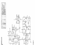
2 2 2 HARTREY AVE., EVANSTON. IL. 6 0 2 0 4 U.S.A.
@
AREA CODE 3 1 2 / 3 2 8 - 9 0 0 0
.
CABLE: SHUREMICRO
I
SHEET
DATA
1
MODEL M62V
AUDIO LEVEL CONTROLLER
MODEL M62V AUDIO LEVEL CONTROLLER
Permits any number of microphones to be used
GENERAL:
The "Level-Loc" Audio Level Controller is basically a
low-noise preamplifier with unity gain from the microphone level input to the microphone level output or
60 dB of voltage gain from the high-impedance microphone level input to the auxiliary level output. The
input and microphone level output contain matching
transformers so either high- or low-impedance operation may be selected. In addition, a high-impedance
auxiliary output is provided capable of driving any
high-impedance amplifier, mixer or tape recorder input
requiring 1 volt or less. This preamplifier has the additional capability of reducing its gain as the input
signal increases, thereby holding the output signal
constant. After a predetermined input level threshold
is reached the output level is "locked", that is, it
remains constant even if the input signal increases
by as much as 100 times (40 dB). This reduction in
gain, which results in a constant output level, is
obtained without introducing significant distortion or
transients into the program material. The DISTANCE
SELECTOR switch determines the input level at which
gain reduction (Level-Loc action) begins. An INPUT
LEVEL control is also provided that:
1. Can be used as a vernier control to allow fine
adjustment of input threshold between the preset
threshold levels selected by the DISTANCE
SELECTOR switch.
2. Can act as an input attenuator for signals that
are higher than normal microphone levels. Such
inputs may be: signals from microphones used
very close to the mouth, outputs from preamplifiers, line amplifiers, tuners or tape recorders.
The Audio Level Controller: Reduces blasting or large volume increases
when a speaker or entertainer varies his distance and position from the microphone.
Upgrades tape-recording systems and the Audio
portion of Video Tape Recorders, by controlling
the maximum signal level being fed to the recorder. This prevents distortion and overloading
of the tape recorder which might be caused by
"close talking" the microphone, or by very loud
vocal or musical passages.
Copyright 1976, Shure Brothers Inc.
27A823 (PC)
in a paging system or conference arrangement,
without setting the level for each individual
microphone. (For paging systems only low-impedance microphones with normally open switches
should be used.) Any number of these microphones may be operated in parallel across the
low-impedance input of the M62V, the Audio
Level Controller will automatically set a fixed
maximum paging level that cannot be exceeded.
SPECIFICATIONS
lnput lmpedance (below threshold):
High Impedance: 50 kilohms
Low Impedance: 300 ohms (for 25 to 600 ohm
sources)
lnput Levels:
High Impedance: Microphone
max. (using
control)
Low Impedance: Microphone
max. (using
control)
level to 10 volts
INPUT LEVEL
level to .2 volt
INPUT LEVEL
Output Impedance:
High lmpedance Microphone Level: 3.3 kilohms
Minimum recommended load: 5 kilohms
Low lmpedance Microphone Level: Less than 50
ohms
Minimum recommended load: 25 ohms
Aux. Output: 10 kilohms
Minimum recommended load: 10 kilohms
Gain Characteristics: I Below threshold, INPUT LEVEL
control maximum (10) DISTANCE SELECTOR in
"18" or More" position; measured from input to
output]
OUTPUT
INPUT
Hi
Imp. Mic.
Lo Imp. Mic.
Aux. Output
Hi Imp. Mic.
Unity
-20 dB
+60 dB
Lo Imp. Mic.
+20 dB
Unity
+80 dB
Frequency Response:
i 2 dB 40 to 20,000 Hz
Printed in
U.S.A.
Maximum Output Noise (HI IMPEDANCE MIC. OUTPUT, in dB below 1 volt):
300-20.000 H z
(Noise)
30-20,000 H z
( H u m a n d Noise)
Lo Imp. lnput
150 ohm Termination
-103
dB
-95
dB
Hi Imp. lnput
33 kilohm Termination
-104 dB
-95
dB
switch above the receptacle. This output is designed
to work into a 25- to 600-ohm microphone line or
microphone input, or into a high-impedance amplifier
or tape recorder microphone input. The receptacle
is a professional three-pin male audio connector.? See
Figure 2B for microphone level output receptacle connections.
SHIELD
.
-.
- - --
Distortion (any level of regulation):
3% maximum THD
,T
I1
j
Dynamic Characteristics: Fast attack, moderate recovery, fixed.
Attack: For a 20 dB step increase above threshold, gain is within 2 dB of final value in
500 microseconds.
Recovery: For a 20 dB step decrease to threshold, gain is within 2 dB of final value
in 700 milliseconds.
Battery Life: Approximately 200 hours
Dimensions: See Figure 5.
Net Weight:
1 kg (2.2 Ib)
MIC. OUTPUT
MIC
/8
.
.
.
.
.
.
.
.
.A,,
OUTPUT
HIGH IMPEDANCE
LOW IMPEDkNCE
IBALANCEO LINE)
MICROPHONE OUTPUT PLUG CONNECTIONS
FIGURE 2 8
The receptacle marked AUX. OUTPUT i s a phono
pin jack which accepts a standard phono pin plug.
This output is designed to work into a high-impedance
(10 kilohms or greater), high-level input of a mixer,
preamplifier, amplifier, or tape recorder. This output
may be connected to the AUX. INPUT of an M68 Series
Mixer, the HIGH-LEVEL INPUT of an M63 Audio Master
or the LINE INPUT (bridging) of an M67 Professional
Microphone Mixer.
The static characteristics of the high-level AUX.
OUTPUT are shown in Figure I B . This output provides
a constant 1 volt level (with a 47-kilohm load) whenever the input level is above threshold. Below threshold it provides approximately 60 dB of gain over the
HI-IMP MIC. input.
NOTE: This output is disabled when the MASTER
CONTROL switch is set to "Bypass."
3I
-90
-80
-70 -60
-50
-40
-30
-20
-10
0
Battery and Auxiliary Power Connections:
The battery to power the M62V i s shipped with the
unit but must be installed. Install as follows:
1. Remove Battery Compartment cover by removing
the lower slotted screw holding cover, loosening
the upper screw, and sliding the cover down.
2. Snap battery into clips provided.
3. Replace Battery Compartment cover and tighten
screws securely.
H I IMP
MIC.
INPUT VOLTAGE (DBV)
DBV
-
VOLTS RM5 RE I V
STATIC INPUT-OUTPUT CHARACTERISTICS
(INPUT LEVEL CONTROL MAXIMUH)
FIGURE 1
lnput Connections: The receptacle marked MIC. INPUT
is designed for either low (25- to 600-ohms) - or highimpedance (50,000-ohms) inputs. The impedance is
selected by a slide switch above the input receptacle.
The unit is not recommended for use with crystal or
ceramic microphones.
The input receptacle is a professional three-pin
female audio connector.? See Figure 2A for low- and
high-impedance connections to receptacle.
..-
--
-.. INPUT
-- -.
LOW IMPEDANCE
(BALANCED LINE)
INPUT
HIGH IMPEDANCE
INPUT PLUG CONNECTIONS
FIGURE 2A
Output Connections: The receptacle marked MIC.
OUTPUT is a dual-impedance output selected by the
Designed to mate with Cannon XL series, Switchcraft A3
(Q.G.) series or equivalent connector. [Shure part 95,4407
(male) or 95A548 (female)].
Battery Replacement-Use
or equivalent 9V Battery.
Eveready type 216 or 222,
AUX. INPUT POWER: This jack is used as a power
input when using the power supply of a Shure M67 or
M68 Series Mixer or M63 Audio Master. In this
case, the battery should be disconnected. A special
connecting cable is provided to connect the AUX.
INPUT POWER jack on the M62V to the ACCESSORY
28 V. D.C. jack on the M68 Mixer or to the POS. (red)
30 V. D.C. jack on the M67 Mixer or M63 Audio Master.
In order to utilize ac current, the use of a 9 volt
D.C. Battery Eliminator is suggested. There is a provision i n the battery compartment cover that will allow
using a 9 Vdc Battery Eliminator to power the M62V.
The Battery Eliminator cable is to be slipped into the
split rubber grommet on the cover of the battery compartment. To secure cable, rotate grommet Y2 turn.
Connection is to be made using the same battery
clips that normally connect to the 9 volt battery.
Or a Battery
(Note: If a Shure M683 M67 Or M63r
Eliminator is to be used, first remove the battery.)
Page 2
CONTROLS AND OPERATION
MASTER CONTROL:
With the MASTER CONTROL in the "Bypass"
position:
1. The battery is disconnected from the "Level-Loc"
circuitry and thus the level-controlling action of
the M62V is inoperative.
2. The AUX. OUTPUT is disabled.
3. The input to the M62V is switched directly to the
MIC. LEVEL OUTPUT so in this "Bypass" condition the unit can serve as a microphone line
matching transformer.
With the MASTER CONTROL switch in the "LevelLoc" position, the unit is energized, its level-controlling capability operates, and the AUX. OUTPUT
is available.
DISTANCE SELECTOR:
When the M62V is being fed directly from a microphone source, optimum Level-Loc action is usually
obtained when the INPUT LEVEL control is set to
maximum (10) and the DISTANCE SELECTOR is set for
the actual performer-to-microphone distance. For example: a singer or soloist standing nominally 6 inches
from a microphone would require a setting of "6" or
Less" on the DISTANCE SELECTOR. A panel discussion where the speaker(s) may be any distance up to
18 inches or more, would require a setting of "18" or
More" on the DISTANCE SELECTOR.
For maximum signal-to-noise ratio use the "6" or
Less" position of the DISTANCE SELECTOR unless
the input signal level is not sufficient to produce the
desired Level-Loc action.
When recording in quiet surroundings, the 18"
setting of the DISTANCE SELECTOR may be used to
obtain maximum control of the recorded level. This
is especially advantageous in recording sound sources
where the volume is not predictable. If under these
conditions, very loud program material or high sensitivity microphones result in distortion, the DISTANCE
SELECTOR may be changed from the "18" or More"
position to the "12"" or "6" or Less" position. (Each
position represents a 6 dB change in threshold.) In
extreme cases of overload the INPUT LEVEL control
can be reduced (see INPUT LEVEL CONTROL).
When using the Audio Level Controller in a publicaddress system, with the MASTER CONTROL in the
"Level-Loc" position, turn up the volume control on the
public-address amplifier to that point where the system
is just below the threshold of feedback with no one
speaking into the microphone. In this manner, the
total system gain is reduced as signal above threshold
is applied, and the system is more stable during loud
parts of the performance. Should accidental feedback
occur, the M62V will prevent it from becoming "earsplitting" or damaging the loudspeakers.
The Level-Loc action may be demonstrated by
switching from the "Level-Loc" to the "Bypass" position of the MASTER CONTROL, provided the MIC.
OUTPUT i s being used.
Figure 1 illustrates the static input-output characteristics of the Audio Level Controller, with the INPUT
LEVEL control at maximum using the high-impedance
input and high-impedance microphone level output.
(Note: there is a 20 dB level difference between the
"Hi Imp." and "Lo Imp." setting of the MIC OUTPUT.
A high-impedance to low-impedance transformer, as
used in the input or output of the M62V, gives a 20 dB
reduction of voltage gain.)
As an example, consider the DISTANCE SELECTOR
switch set to the "18" or More" position. As the input
is increased from a low value say -80 dBV (-80 dBV
means 80 d B below 1 volt or . I millivolt), the output
will increase as much as the input until point A, the
"threshold," (the input level at which compression
takes place), is reached. Above this input level ( - 5 6
dBV), the output will remain nearly constant over an
input range of 40 dB'or more, as represented by curve
A-A' (on Figure 1A).
The input threshold voltage, and consequently the
regulated output level, may be increased by either 6
or 12 dB by changing the setting of the DISTANCE
SELECTOR. In this case, operation above the input
threshold is represented by curves B-B' or C-C', according to the setting. These threshold voltages have
been chosen to approximate the output of a typical
microphone with an average speaker at the distances
labeled on the switch. At greater distances or quieter
speech, the output will follow the input, but i f the
person speaking is louder or closer to the microphone,
the Audio Level Controller will prevent its output from
increasing, thus eliminating "blasting" or overloading
of subsequent electronics.
INPUT LEVEL CONTROL:
The INPUT LEVEL control is employed when a
higher-than-normal signal level is fed into the M62V,
such as the output of preamplifiers, line amplifiers,
tape recorders or tuners. The INPUT LEVEL control
may also be used as a vernier control to allow fine
adjustments of the input threshold that may occur
between the 6 dB steps of the preset "DISTANCE
SELECTOR" switch.
High-impedance, unbalanced signals up to 10 volts
can be applied to the high-impedance input; lowimpedance, balanced signals no greater than 200
millivolts may be connected directly to the low-impedance input. If the low-impedance signal is greater
than this (for example, a 600 ohm line at + 4 dBm),
a line adapter balanced attenuator such as the Shure
A15LA may be connected between the line and the
input of the M62V. Alternately, i f the line can be unbalanced (one side grounded), it may be connected
to the high-impedance input with no attenuator.
With such inputs, the DISTANCE SELECTOR should
be set to the "6" or Less" position. To adjust the INPUT
LEVEL control, monitor the output of the M62V and
apply an average level input. Starting at 0, advance
the INPUT LEVEL control. The signal will begin to
appear at the output and will increase in volume
until a point is reached at which no further increase
is noted. This is the threshold, and if the control is
left at this setting, any inputs less than the test input
level will pass through the M62V uncontrolled, while
those which are louder will be prevented from rising
and overloading succeeding equipment. Operation of
the Audio Level Controller above the constant output
region is not recommended. The curves shown on
Figure 1A and B are valid when the INPUT LEVEL
control is used; however, the appropriate attenuation must be added to the Input Voltage (Horizontal)
Scale. For example, if the INPUT LEVEL control is
set to "5" aproximately 20 dB should be added to
the input voltage figures, so the point marked -60
dBV on the input voltage scale (Horizontal) would
become -40 dBV. In other words, the entire curve
would be shifted 20 dB to the right.
TO USE WlTH SHURE M68 SERIES MICROPHONE
MIXERS:
The two ways of using the M62V with the M68
Series Mixers are:
1. Connect a microphone directly to the microphone
input of the M62V. Set INPUT IMPEDANCE
switch to appropriate position. Connect the microphone level output of the M62V (Hi or Lo
Impedance) to a microphone input on the M68
mixer (either Hi or Lo Impedance, whichever
was selected on the M62V). This method gives
audio "Level-Loc" control on the one microphone attached to the M62V ONLY. All other
inputs to the M68 are unaffected.
2. Connect the M62V to control ALL inputs of the
M68 mixer, by connecting the microphone level
output of the M68 to the input of the M62V, (if
the low-impedance microphone level output of
the M68 is used the M62V input must be set to
"Lo Impedance," if the high-impedance microphone level output of the M68 is used, the M62V
input must be set to "Hi Impedance") or connect
the AUX. HIGH LEVEL OUTPUT of the M68 to
the input (set for "Hi Impedance") of the M62V.
(The INPUT LEVEL control may be used to control the threshold level as covered under "INPUT
LEVEL CONTROL.") The input for the main amplifier or tape recorder is then connected to the
M62V microphone level output (Hi or Lo Impedance) or the AUX. OUTPUT. When used in this
manner, the MASTER CONTROL of the M68
Mixer should be set to about "5" and the individual controls used to adjust the proper blend
between the channels. If more overall volume is
required, the volume control on the main amplifier should be advanced. This precaution will
prevent equipment overload.
TO USE WlTH SHURE M67 MICROPHONE MIXER:
Follow the instructions above for the M68, but only
the low-impedance input or output may be used when
connected to the M67. The setting of the M67 controls
only need be such that the VU meter indicates properly
to avoid overload.
TO USE WlTH SHURE M63 AUDIO MASTER:
Follow the instructions above but only the AUX.
OUTPUT of the M62V may be used to feed the HI
LEVEL INPUT of the M63. The setting of the M63
VOLUME control will control the overall system gain
after the "Level-Loc".
OPERATION HINTS:
Remember that the M62V "Level-Loc" is a device
that provides a constant output level after a predetermined input level (threshold) is reached, therefore, if
more system gain is needed i n PA applications or a
higher record level is desired in tape recording applications, DO NOT INCREASE THE INPUT LEVEL GOING
INTO THE "LEVEL-LOC;" once input threshold has
been reached the output level becomes fixed IT CAN
NOT GO ANY HIGHER. For more system gain, increase
the gain control of amplifier, preamplifier or tape recorder that is being fed from the M62V.
Note: For best results it is recommended that some
time be spent in experimentation with the
"Level-Loc" to enable the user to become accustomed to the advantages which this unit
presents.
Guarantee: This Shure product is guaranteed in normal
use to be free from electrical and mechanical defects
for a period of one year from the date of purchase.
Please retain proof of purchase date. This guarantee
includes all parts and labor.
Shipping Instructions: Carefully repack the unit and
return it prepaid to the factory. If outside the United
States, return the unit to your dealer or Authorized
Shure Service Center for repair. The unit will be returned to you prepaid.
M62V Modification for
Non-disabling Aux. Output
The M62V may be rewired internally so that the AUX.
OUTPUT will operate (without "Level-Loc" action) when
the MASTER CONTROL is set to "Bypass", rather than
being disabled. This option is useful when the M62V
AUX. OUTPUT is connected to the auxiliary input of the
M63 Audio Master or M68 Series Mixers. Note: With
this option, the M62V power cannot be turned off by
the MASTER CONTROL switch. Power should be supplied to the M62V from an external source such as the
ACCESSORY 28 V. D.C. jack on the M68 Mixer or the
POS. (red) 30 V. D.C. jack on the M67 Mixer or M63
Audio Master, and the internal battery must be removed.
To make this modification (see Figures 3 and 4):
1. Remove battery from unit.
2. Remove cover from unit.
3. Unsolder and remove wire between MASTER
CONTROL switch S3, terminal #8, and terminal
strip end of 10 kilohm, Y2 watt resistor.
4. Unsolder wire from S3, terminal #7, and solder it
to terminal strip end of 10 kilohm, Y2 watt resistor.
5. Unsolder positive end of 2 mfd x 15 volt capacitor
from collector of Q3.
6. Connect a wire from positive lead of 2 x 15 capacitor to S3, terminal #8.
7. Connect a wire from collector of Q3 to S3, terminal #7.
8. Connect a wire from center terminal of INPUT
LEVEL control R1 to S3, terminal #9.
9. Install a jumper wire between terminals # 4 and
#5 of S3.
10. Replace cover of unit, but do not install battery if
the M62V is to be powered from an external
source.
MASTER CONTROL SWITCH 53
TERMINAL DESIGNATIONS
(REAR VIEW)
A68L LOCKING PANEL
The A68L Panel fastens over the controls of the
M62V, M63, M67 or M68 Series Mixers, locks in place
with a padlock (supplied), and prevents tampering with
controls once they have been set. The A68L Kit contains locking panel, small padlock and two keys.
MASTER CONTROL
9
i
I
SCHEMATIC CHANGES FOR MODIFICATION
FIGURE 4
A68L LOCKING PANEL
OVERALL DIMENSIONS
FIGURE 5
A68R RACK PANEL KIT
OPTIONAL ACCESSORIES
A68S Stacking Kit
The A68S Kit enables you to conveniently stack
together t h e M62V with the M63, M67 or M68 Series
Mixers. An interconnecting cable is provided for connecting the AUX. OUTPUT of the M62V to the M68
Series Mixers or an M63 Audio Master. Additional units
can be stacked with the use of additional A68S Kits.
The Stacking Kit includes two brackets and an interconnecting cable.
Designed to mount M62V Audio Level Controller i n
standard 19" rack.
Installation and Mounting
1 . Assemble brackets to panel using hardware
supplied.
2. Remove two cover mounting screws from bottom
of M62V.
3. Slide M62V into brackets and re-assemble screws
through brackets into bottom of mixer.
A68SC Interconnecting Cable
Cable only, as supplied i n the A68S Stacking Kit,
for use in connecting the AUX OUTPUT of the M62V
to an M68 Series Mixer (AUX INPUT) or M63 Audio
Controller. The A68SC is a 305 mm (12 in.) long single
conductor shielded cable with a phono plug on each
end.
A68C OUTPUT CABLE KIT
The A68C Output Cable Kit provides a convenient
and flexible method of connecting the microphone
level output of the M62V, M63, M67 or M68 Series
Mixers to the great variety of amplifier and input receptacle configurations. Enables you to connect to
virtually any PA system. Kit includes:
One 4.6 m (15 ft) two-conductor shielded cable
with professional three-pin male and female
audio connectors.?
One 305 mm (12 in.) two-conductor shielded
adapter cable with professional three-pin female
audio connector on one end and Hubbel twist
lock plug on other end.
One 305 mm (12 in.) single conductor shielded
adapter cable with professional three-pin female
audio connector on one end and Amphenol type
MCI connector on the other end.
One Phone Plug adapter for use with MC1 Connector.
NOTE:
The A68L Locking Panel may be used
simultaneously with the A68R Rack Panel
Kit.
A68R RACK PANEL K I 1
AC60
ATTACH^
CARRYING CASE
The AC60 is a vinyl-covered attache type carrying
case (compartmentalized and foam lined), with space
for any of the M62V, M63, M67 or M68 Series Mixers
and as many as four microphones, cables, adapters,
and other accessories.
A68C OUTPUT CABLE K I T
t Designed
to mate with Cannon XL series, Switchcraft A3
(Q.G.) series or equivalent connector.
Page 5
CHASSIS GROUND
h
CIRCUIT
COMMON
I-.
3. THE FOLLOWING SYMBOLS DENOTE:
2. ALL RESISTORS 5 10% TOLERANCE AND 1/4 WATT
UNLESS OTHERWISE SHOWN.
NOTES :
I. ALL CAPACITORS I N MFD AND 100 VOLTS OR MORE
UNLESS OTHERWISE SHOWN.
ELECTROLYTIC
CAPACITORS SHOWN IN MFD x VOLTS.
POWER 28 V.D.C.
TI
FIGURE 6
-
MODEL M62V AUDIO LEVEL CONTROLLER
CIRCUIT DIAGRAM
B+
DISTANCE SELECTOR
A+
=-
46A021
9082150
55A54
55A120
55A62
RI
TI.T2
SI.S2
S3
54
-
-
86A335
86A329
96.97
99
QTY
O
IN KIT]
PARTS LIST
DESCRIPTION
NPN TRANSISTOR, SILICON. SELECTED HIGH
GAIN. LOW NOISE SIMILAR TO MOTOROLA
N5088
- 2.
RKC66
PNP TRANSISTOR, SILICON,TI TIS93
- _I
N-CHANNEL JUNCTION FIELD EFFECT
TRANSISTOR. MOTOROLA 2 N 5 4 5 8
POTENTIOMETER,5OK, AUDIO TAPER
I
RKC3
AUDIO TRANSFORMER AND SHIELD ASSEMBLY.
I.
RKC2.3 __SWITCH. SLIDE. D P D T
RKClO
4
SWITCH, SLIDE. TPDT
RKCll -I
SWITCH,SLIDE. DPTT
1
4
~
ITEM !SHURE PART NO!S*RE
. . K
86A349
PI-Q5,Q8
RKC9