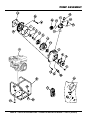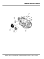
1
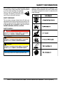
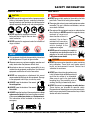
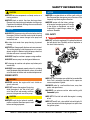
OPERATION AND PARTS MANUAL MODEL QP2H CENTRIFUGAL PUMP (HONDA GX120UT2PX2 GASOLINE ENGINE) Revision #1 (01/29/14) To find the latest revision of this publication, visit our website at: www.multiquip.com THIS MANUAL MUST ACCOMPANY THE EQUIPMENT AT ALL TIMES. PROPOSITION 65 WARNING PAGE 2 — QP2H CENTRIFUGAL PUMP • OPERATION AND PARTS MANUAL — REV. #1 (01/29/14) NOTES QP2H CENTRIFUGAL PUMP • OPERATION AND PARTS MANUAL — REV. #1 (01/29/14) — PAGE 3 TABLE OF CONTENTS QP2H Centrifugal Pump Proposition 65 Warning............................................ 2 Table Of Contents..................................................... 4 Parts Ordering Procedures....................................... 5 Safety Information............................................... 6-10 Specifications (Pump)............................................. 11 Specifications (Engine)........................................... 12 General Information................................................ 13 Pump Components................................................. 14 Basic Engine........................................................... 15 Inspection (Engine)................................................. 16 Setup...................................................................... 17 Operation........................................................... 18-19 Maintenance (Pump)......................................... 20-21 Maintenance (Engine)....................................... 22-24 Storage................................................................... 25 Troubleshooting (Engine/Pump)........................ 26-27 Explanation Of Code In Remarks Column............. 28 Suggested Spare Parts.......................................... 29 Component Drawings Pump Assembly................................................. 30-31 Engine Service Parts......................................... 32-33 Terms and Conditions of Sale — Parts.................. 34 NOTICE Specifications and part numbers are subject to change without notice. PAGE 4 — QP2H CENTRIFUGAL PUMP • OPERATION AND PARTS MANUAL — REV. #1 (01/29/14) www.multiquip.com PARTS ORDERING PROCEDURES Ordering parts has never been easier! Choose from three easy options: Order via Internet (Dealers Only): Best Deal! Effective: January 1st, 2006 If you have an MQ Account, to obtain a Username and Password, E-mail us at: parts@multiquip. com. Order parts on-line using Multiquip’s SmartEquip website! ■ View Parts Diagrams ■ Order Parts ■ Print Specification Information To obtain an MQ Account, contact your District Sales Manager for more information. Use the internet and qualify for a 5% Discount on Standard orders for all orders which include complete part numbers.* Goto www.multiquip.com and click on Order Parts to log in and save! Note: Discounts Are Subject To Change Order via Fax (Dealers Only): All customers are welcome to order parts via Fax. Domestic (US) Customers dial: 1-800-6-PARTS-7 (800-672-7877) Fax your order in and qualify for a 2% Discount on Standard orders for all orders which include complete part numbers.* Note: Discounts Are Subject To Change Order via Phone: Domestic (US) Dealers Call: 1-800-427-1244 Non-Dealer Customers: Contact your local Multiquip Dealer for parts or call 800-427-1244 for help in locating a dealer near you. International Customers should contact their local Multiquip Representatives for Parts Ordering information. When ordering parts, please supply: ❒ ❒ ❒ ❒ ❒ ❒ Dealer Account Number Dealer Name and Address Shipping Address (if different than billing address) Return Fax Number Applicable Model Number Quantity, Part Number and Description of Each Part ❒ Specify Preferred Method of Shipment: ✓ UPS/Fed Ex ✓ DHL ■ Priority One ✓ Truck ■ Ground ■ Next Day ■ Second/Third Day NOTICE All orders are treated as Standard Orders and will ship the same day if received prior to 3PM PST. WE ACCEPT ALL MAJOR CREDIT CARDS! QP2H CENTRIFUGAL PUMP • OPERATION AND PARTS MANUAL — REV. #1 (01/29/14) — PAGE 5 SAFETY INFORMATION Do not operate or service the equipment before reading the entire manual. Safety precautions should be followed at all times when operating this equipment. Failure to read and understand the safety messages and operating instructions could result in injury to yourself and others. Potential hazards associated with the operation of this equipment will be referenced with hazard symbols which may appear throughout this manual in conjunction with safety messages. SAFETY MESSAGES The four safety messages shown below will inform you about potential hazards that could injure you or others. The safety messages specifically address the level of exposure to the operator and are preceded by one of four words: DANGER, WARNING, CAUTION or NOTICE. SAFETY SYMBOLS DANGER Indicates a hazardous situation which, if not avoided, WILL result in DEATH or SERIOUS INJURY. WARNING Indicates a hazardous situation which, if not avoided, COULD result in DEATH or SERIOUS INJURY. CAUTION Indicates a hazardous situation which, if not avoided, COULD result in MINOR or MODERATE INJURY. NOTICE Addresses practices not related to personal injury. PAGE 6 — QP2H CENTRIFUGAL PUMP • OPERATION AND PARTS MANUAL — REV. #1 (01/29/14) SAFETY INFORMATION GENERAL SAFETY CAUTION NEVER operate this equipment without proper protective clothing, shatterproof glasses, respiratory protection, hearing protection, steel-toed boots and other protective devices required by the job or city and state regulations. NEVER operate this equipment when not feeling well due to fatigue, illness or when under medication. NEVER operate this equipment under the influence of drugs or alcohol. PUMP SAFETY DANGER NEVER pump volatile, explosive, flammable or low flash point fluids. These fluids could ignite or explode. The engine fuel exhaust gases contain poisonous carbon monoxide. This gas is colorless and odorless, and can cause death if inhaled. The engine of this equipment requires an adequate free flow of cooling air. NEVER operate this equipment in any enclosed or narrow area where free flow of the air is restricted. If the air flow is restricted it will cause injury to people and property and serious damage to the equipment or engine. DANGEROUS GAS FUMES NOTICE This equipment should only be operated by trained and qualified personnel 18 years of age and older. Whenever necessary, replace nameplate, operation and safety decals when they become difficult read. Manufacturer does not assume responsibility for any accident due to equipment modifications. Unauthorized equipment modification will void all warranties. NEVER use accessories or attachments that are not recommended by Multiquip for this equipment. Damage to the equipment and/or injury to user may result. ALWAYS know the location of the nearest fire extinguisher. ALWAYS know the location of the nearest first aid kit. ALWAYS know the location of the nearest phone or keep a phone on the job site. Also, know the phone numbers of the nearest ambulance, doctor and fire department. This information will be invaluable in the case of an emergency. NEVER operate the equipment in an explosive atmosphere or near combustible materials. An explosion or fire could result causing severe bodily harm or even death. WARNING NEVER pump corrosive chemicals or water containing toxic substances. These fluids could create serious health and environmental hazards. Contact local authorities for assistance. NEVER open the priming plug when pump is hot. Hot water inside could be pressurized much like the radiator of an automobile. Allow pump to cool to the touch before loosening plug. The possibility exists of scalding, resulting in severe bodily harm. NEVER disconnect any emergency or safety devices. These devices are intended for operator safety. Disconnection of these devices can cause severe injury, bodily harm or even death. Disconnection of any of these devices will void all warranties. QP2H CENTRIFUGAL PUMP • OPERATION AND PARTS MANUAL — REV. #1 (01/29/14) — PAGE 7 SAFETY INFORMATION CAUTION NEVER lubricate components or attempt service on a running machine. NEVER block or restrict flow from discharge hose. Remove kinks from discharge line before starting pump. Operation with a blocked discharge line can cause water inside pump to overheat. NOTICE ALWAYS fill the pump casing with water before starting the engine. Failure to maintain water inside the pump housing will cause severe damage to the pump and mechanical seal. In winter drain water from pump housing to prevent freezing. NOTICE NEVER run engine without an air filter or with a dirty air filter. Severe engine damage may occur. Service air filter frequently to prevent engine malfunction. NEVER tamper with the factory settings of the engine or engine governor. Damage to the engine or equipment can result if operating in speed ranges above the maximum allowable. FUEL SAFETY DANGER DO NOT add fuel to equipment if it is placed inside truck bed with plastic liner. Possibility exists of explosion or fire due to static electricity. NEVER start the pump with the clean-out cover removed. The rotating impeller inside the pump can cut or sever objects caught in it. Before starting the pump, check that the clean-out cover is securely fastened. ALWAYS keep the machine in proper running condition. ALWAYS ensure pump is on level ground before use. Fix damage to machine and replace any broken parts immediately. ALWAYS store equipment properly when it is not being used. Equipment should be stored in a clean, dry location out of the reach of children and unauthorized personnel. ENGINE SAFETY WARNING NEVER operate the engine with heat shields or guards removed. DO NOT remove the engine oil drain plug while the engine is hot. Hot oil will gush out of the oil tank and severely scald any persons in the general area of the pump. CAUTION NEVER touch the hot exhaust manifold, muffler or cylinder. Allow these parts to cool before servicing equipment. DO NOT start the engine near spilled fuel or combustible fluids. Fuel is extremely flammable and its vapors can cause an explosion if ignited. ALWAYS refuel in a well-ventilated area, away from sparks and open flames. ALWAYS use extreme caution when working with flammable liquids. DO NOT fill the fuel tank while the engine is running or hot. DO NOT overfill tank, since spilled fuel could ignite if it comes into contact with hot engine parts or sparks from the ignition system. PAGE 8 — QP2H CENTRIFUGAL PUMP • OPERATION AND PARTS MANUAL — REV. #1 (01/29/14) SAFETY INFORMATION Store fuel in appropriate containers, in well-ventilated areas and away from sparks and flames. NEVER use fuel as a cleaning agent. DO NOT smoke around or near the equipment. Fire or explosion could result from fuel vapors or if fuel is spilled on a hot engine. BATTERY SAFETY (ELECTRIC START ONLY) DANGER DO NOT drop the battery. There is a possibility that the battery will explode. DO NOT expose the battery to open flames, sparks, cigarettes, etc. The battery contains combustible gases and liquids. If these gases and liquids come into contact with a flame or spark, an explosion could occur. WARNING ALWAYS wear safety glasses when handling the battery to avoid eye irritation. The battery contains acids that can cause injury to the eyes and skin. Use well-insulated gloves when picking up the battery. ALWAYS keep the battery charged. If the battery is not charged, combustible gas will build up. CAUTION ALWAYS disconnect the NEGATIVE battery terminal before performing service on the equipment. ALWAYS keep battery cables in good working condition. Repair or replace all worn cables. TRANSPORTING SAFETY CAUTION NEVER allow any person or animal to stand underneath the equipment while lifting. NOTICE Before lifting, make sure that the equipment parts (hook and vibration insulator) are not damaged and screws are not loose or missing. Always make sure crane or lifting device has been properly secured to the lifting bail (hook) of the equipment. ALWAYS shutdown engine before transporting. NEVER lift the equipment while the engine is running. Tighten fuel tank cap securely and close fuel cock to prevent fuel from spilling. Use adequate lifting cable (wire or rope) of sufficient strength. Use one point suspension hook and lift straight upwards. DO NOT charge battery if frozen. Battery can explode. When frozen, warm the battery to at least 61°F (16°C). ALWAYS recharge the battery in a well-ventilated environment to avoid the risk of a dangerous concentration of combustible gases. If the battery liquid (dilute sulfuric acid) comes into contact with clothing or skin, rinse skin or clothing immediately with plenty of water. If the battery liquid (dilute sulfuric acid) comes into contact with eyes, rinse eyes immediately with plenty of water and contact the nearest doctor or hospital to seek medical attention. DO NOT lift machine to unnecessary heights. ALWAYS tie down equipment during transport by securing the equipment with rope. QP2H CENTRIFUGAL PUMP • OPERATION AND PARTS MANUAL — REV. #1 (01/29/14) — PAGE 9 SAFETY INFORMATION ENVIRONMENTAL SAFETY/DECOMMISSIONING NOTICE EMISSIONS INFORMATION NOTICE Decommissioning is a controlled process used to safely retire a piece of equipment that is no longer serviceable. If the equipment poses an unacceptable and unrepairable safety risk due to wear or damage or is no longer cost effective to maintain (beyond life-cycle reliability) and is to be decommissioned (demolition and dismantlement),be sure to follow rules below. The gasoline engine used in this equipment has been designed to reduce harmful levels of carbon monoxide (CO), hydrocarbons (HC) and nitrogen oxides (NOx) contained in gasoline exhaust emissions. DO NOT pour waste or oil directly onto the ground, down a drain or into any water source. Attempting to modify or make adjustments to the engine emmission system by unauthorized personnel without proper training could damage the equipment or create an unsafe condition. Contact your country's Department of Public Works or recycling agency in your area and arrange for proper disposal of any electrical components, waste or oil associated with this equipment. When the life cycle of this equipment is over, remove battery and bring to appropriate facility for lead reclamation. Use safety precautions when handling batteries that contain sulfuric acid. When the life cycle of this equipment is over, it is recommended that the trowel frame and all other metal parts be sent to a recycling center. This engine has been certified to meet US EPA Evaporative emissions requirements in the installed configuration. Additionally, modifying the fuel system may adversely affect evaporative emissions, resulting in fines or other penalties. Emission Control Label The emission control label is an integral part of the emission system and is strictly controlled by regulation(s). The label must remain with the engine for its entire life. If a replacement emission label is needed, please contact your authorized engine distributor. Metal recycling involves the collection of metal from discarded products and its transformation into raw materials to use in manufacturing a new product. Recyclers and manufacturers alike promote the process of recycling metal. Using a metal recycling center promotes energy cost savings. PAGE 10 — QP2H CENTRIFUGAL PUMP • OPERATION AND PARTS MANUAL — REV. #1 (01/29/14) SPECIFICATIONS (PUMP) Pump Table 1. Specifications (Pump) Model Type Suction and Discharge Size Maximum Pumping Capacity Max. Lift Max. Head Max. Pressure Dry Net Weight QP2H Centrifugal Pump 2.00 in. (51 mm.) 158 gallons/minute (600 liters/minute) 25 ft. (7.62 m) 115 ft. (35 m) 50 psi (345 kPa) 53 lb. (24 Kg.) 14.30 IN. (363 MM.) 14.72 IN. (374 MM.) 18.90 IN. (480 MM.) Figure 1. QP2H Dimensions QP2H CENTRIFUGAL PUMP • OPERATION AND PARTS MANUAL — REV. #1 (01/29/14) — PAGE 11 SPECIFICATIONS (ENGINE) Engine Dimension (L x W x H) Dry Net Weight Table 2. Specifications (Engines) Model HONDA GX120UT2PX2 Air-cooled 4 stroke, Single Cylinder, OHV, Type Horizontal Shaft Gasoline Engine 2.40 in. x 1.60 in. Bore x Stroke (60 mm x 42 mm) Displacement 118 cc (7.3 cu-in) Max Output 4.0 H.P./3,600 R.P.M. Approx. 0.53 U.S. Gallons Fuel Tank Capacity (2.0 Liters) Fuel Unleaded Automobile Gasoline Lube Oil Capacity 0.59 quarts (0.56 liters) Speed Control Method Centrifugal Fly-weight Type Starting Method Recoil Start 11.7 x 13.4 x 12.5 in. (297 x 341 x 318 mm) 28.7 lbs (13 Kg.) 23.3 FT 16.7 FT 10 FT 3.3 FT Figure 2. QP2H Performance Curve PAGE 12 — QP2H CENTRIFUGAL PUMP • OPERATION AND PARTS MANUAL — REV. #1 (01/29/14) GENERAL INFORMATION APPLICATION The QP2H Centrifugal Pump is designed to handle all types of clear water applications. It is ideal for residential use such as dewatering basements and swimming pools. Both the suction and discharge ports on the QP2H pump use a 2-inch diameter opening, which allows the pump to pump at a rate of approximately 158 gallons/minute (gpm) or 600 liters/minute (lpm). Centrifugal or self priming pumps are designed to purge air from the suction line and create a partial vacuum in the pump body. The reduced atmospheric pressure inside the pump allows water to flow through the suction line and into the pump body. The centrifugal force created by the rotating impeller pressurizes the water and expels it from the pump. POWER PLANT This centrifugal pump is powered by a 4.0 horsepower air cooled 4-stroke, single cylinder HONDA GX120 gasoline engine that incorporates a low “Oil Alert Feature.” OIL ALERT FEATURE In the event of low oil or no oil, the HONDA GX120 engine has a built-in oil alarm engine shut-down feature. In the event the oil level is low the engine will automatically shutdown. NEVER place the pump on soft soil. The suction hose or pipe connection should always be checked for tightness and leaks. A small suction leak in the hose or fittings could prevent the pump from priming. Elevation Higher elevations will effect the performance of the pump. Due to less atmospheric pressure at higher altitudes, pumps DO NOT have the priming ability that they have at sea level. This is due to the “thinner air” or lack of oxygen at higher altitudes. A general rule of thumb is that for every 1,000 feet of elevation above sea level a pump will lose one foot of priming ability. For example, in Flagstaff, Arizona where the elevation is approximately 7,000 feet, the pump would have a suction lift of only 18 feet rather than the 25 feet at sea level. Table 3 shows suction lift at various elevations. Table 3. Suction Lift at Various Elevations Altitude Feet Suction Lift in Feet (Meters) (Meters) Sea Level 10.0 (3.048) 15.0 (4.572) 20.0 (6.096) 25.0 (7.620) 2,000 (610) 8.80 (2.680) 13.2 (4.023) 17.6 (5.364) 22.0 (6.705) 4,000 (1,219) 7.80 (2.377) 11.7 (3.566) 15.6 (4.754) 19.5 (5.943) STANDARD CENTRIFUGAL PUMP 6,000 (1,829) 6.90 (2.103) 10.4 (3.169) 13.8 (4.206) 17.3 (5.273) 8,000 (2,438) 6.20 (1.889) 9.30 (2.834) 12.4 (3.779) 15.5 (4.724) Standard centrifugal pumps provide an economical choice for general purpose dewatering. These types of pumps should only be used in clear water applications (agricultural, industrial, residential) as they have a limited solid handling capability of only 10% by volume. 10,000 (3,048) 5.70 (1.737) 8.60 (2.621) 11.4 (3.474) 14.3 (4.358) SUCTION LIFT This pump is intended to be used for de-watering applications and is capable of suction lifts up to 25 feet at sea level. For optimal suction lift performance keep the suction hose or line as short as possible. In general always place the pump as close to the water as possible. PUMP SUPPORT The pump should always be placed on solid stationary ground in a level position. Table 4 shows percentage drops in performance as elevation increases. Table 4. Performance Loss at Various Elevations Altitude Discharge Flow Discharge Head Feet (Meters) Sea Level 100% 100% 2,000 (610) 97% 95% 4,000 (1,219) 95% 91% 6,000 (1,829) 93% 87% 8,000 (2,438) 91% 83% 10,000 (3,048) 88% 78% QP2H CENTRIFUGAL PUMP • OPERATION AND PARTS MANUAL — REV. #1 (01/29/14) — PAGE 13 PUMP COMPONENTS Figure 3 shows a typical application using the QP2H centrifugal pump. Please note that this pump is intended for the removal of clean water. 2 3 4 1 6 5 4 7 8 Figure 3. QP2H Pump Application 4 9 1. Pump — The QP2H is 2-inch centrifugal pump used in general de-watering applications. Typical dewatering applications consist of dewatering basements and swimming pools. 2. Fill Cap — Prior to operation, the pump casing should be filled with water. Remove this cap to add water to the pump. After the initial prime, a sufficient amount of water will be retained in the casing so that the operator will not need to re-prime later. If the casing is dry or has insufficient water, the pump will have difficulty in priming which could lead to premature mechanical seal wear thus causing damage to the pump. 3. Discharge Port — Connect a 2-inch discharge hose to this port. NOTE: CONTACT YOUR NEAREST MULTIQUIP DEALER FOR QUICK DISCONNECT HOSES AND FITTINGS. 6. Suction Port — Connect a 2-inch inlet hose to this port. Use two worm clamps to secure the hose. 7. Suction Hose — Connect this flexible rubber hose to the suction port on the pump. Make sure that the hose lays flat and is not kinked. Use only recommended type suction hose. Contact Multiquip parts department for ordering information. 8. Drain Plug — Remove this plug to drain water from the pump. 9. Strainer — Always attach a strainer to bottom side of the suction hose to prevent large objects and debris from entering the pump. Strainer should be positioned so that it will remain completely under water. Running the pump with the strainer above water for long periods can damage pump. 4. Worm Clamp — Used to secure the hose to the inlet and outlet ports on the pump. Use two clamps to secure the hose on the inlet side of the pump. 5. Discharge Hose — Connect this flexible rubber hose to the discharge port on the pump. Make sure that the hose lays flat and is not kinked. Use only recommended type discharge hose. Contact Multiquip parts department for ordering information. PAGE 14 — QP2H CENTRIFUGAL PUMP • OPERATION AND PARTS MANUAL — REV. #1 (01/29/14) BASIC ENGINE Figure 4. Engine Controls and Components INITIAL SERVICING The engine (See Figure 4) must be checked for proper lubrication and filled with fuel prior to operation. Refer to the manufacturers engine manual for instructions and details of operation and servicing. The engine shown above is a HONDA engine, operation for other types of engines may vary somewhat. 1. Fuel Filler Cap — Remove this cap to add unleaded gasoline to the fuel tank. Make sure cap is tightened securely. DO NOT over fill. DANGER Adding fuel to the tank should be done only when the engine is stopped and has had an opportunity to cool down. In the event of a fuel spill, DO NOT attempt to start the engine until the fuel residue has been completely wiped up, and the area surrounding the engine is dry. 2. Throttle Lever — Used to adjust engine RPM speed (lever advanced forward SLOW, lever back toward operator FAST). 3. Engine ON/OFF Switch — ON position permits engine starting, OFF position stops engine operations. 4. Recoil Starter (pull rope) — Manual-starting method. Pull the starter grip until resistance is felt, then pull briskly and smoothly. 6. Choke Lever — Used in the starting of a cold engine, or in cold weather conditions. The choke enriches the fuel mixture. 7. Air Cleaner — Prevents dirt and other debris from entering the fuel system. Remove wing-nut on top of air filter cannister to gain access to filter element. NOTICE Operating the engine without an air filter, with a damaged air filter, or a filter in need of replacement will allow dirt to enter the engine, causing rapid engine wear. WARNING Engine components can generate extreme heat. To prevent bur ns, DO NOT touch these areas while the engine is running or immediately after operating. NEVER operate the engine with the muffler removed. 8. Spark Plug — Provides spark to the ignition system. Set spark plug gap to 0.6 - 0.7 mm (0.028 - 0.031 inch). Clean spark plug once a week. 9. Muffler — Used to reduce noise and emissions. 10. Fuel Tank — Holds unleaded gasoline. For additional information refer to engine owner's manual. 5. Fuel Valve Lever — OPEN to let fuel flow, CLOSE to stop the flow of fuel. QP2H CENTRIFUGAL PUMP • OPERATION AND PARTS MANUAL — REV. #1 (01/29/14) — PAGE 15 INSPECTION (ENGINE) CAUTION DO NOT attempt to operate the pump untilthe Safety Information, General Information and Inspection sections of this manual have been read and thoroughly understood. 3. Insert and remove the dipstick without screwing it into the filler neck. Check the oil level shown on the dipstick. 4. If the oil level is low (See Figure 6), fill to the edge of the oil filler hole with the recommended oil type (Table 5). Maximum oil capacity is 0.59 quarts (0.56 liters). UPPER LIMIT BEFORE STARTING 1. Read safety instructions at the beginning of manual. 2. Clean the pump, removing dirt and dust, particularly the engine cooling air inlet, carburetor and air cleaner. 3. Check the air filter for dirt and dust. If air filter is dirty, replace air filter with a new one as required. 4. Check carburetor for external dirt and dust. Clean with dry compressed air. 5. Check fastening nuts and bolts for tightness. Engine Oil Check 1. To check the engine oil level, place the pump on secure level ground with the engine stopped. LOWER LIMIT Figure 6. Engine Oil DipStick (Oil Level Season Summer Spring/Fall Winter Table 5. Oil Type Temperature Oil Type 25°C or Higher SAE 10W-30 25°C~10°C SAE 10W-30/20 0°C or Lower SAE 10W-10 2. Remove the filler dipstick from the engine oil filler hole (See Figure 5) and wipe clean. DANGER Motor fuels are highly flammable and can be dangerous if mishandled. DO NOT smoke while refueling. DO NOT attempt to refuel the pump if the engine is hot! or running. Fuel Check 1. Remove the gasoline cap located on top of fuel tank. Figure 5. Engine Oil Dipstick (Removal) 2. Visually inspect to see if the fuel level is low. If fuel is low, replenish with unleaded fuel. 3. When refueling, be sure to use a strainer for filtration. DO NOT top-off fuel. Wipe up any spilled fuel immediately! PAGE 16 — QP2H CENTRIFUGAL PUMP • OPERATION AND PARTS MANUAL — REV. #1 (01/29/14) SETUP 1. Place pump as near to water as possible, on a firm flat, level surface. 2. To prime pump, remove fill cap (See Figure 3) and fill pump casing with water. If the pump casing is not filled with water before starting, it will not begin pumping. 3. Attach suction and discharge hoses to the pump. Check that all hoses are securely attached to the pump. Make certain suction hose (See Figure 3) does not have any air leakage. Tighten hose clamps and couplings as required. 4. It is recommended that 2 clamps be used when securing the suction hose to the inlet side (suction) of the pump. 5. Remember suction hoses must be rigid enough not to collapse when the pump is in operation. 6. Check that the discharge hose (See Figure 3) is not restricted. Place hose so that it lays as straight as it is possible on the ground. Remove any twists or sharp bends from hose which may block the flow of water. NOTICE Suction and discharge hoses are available from Multiquip. Contact your nearest dealer for more information. 7. The discharge hose is usually a collapsible (thin-walled) hose, however if a thin-walled discharge hose is not available, a rigid suction hose can be substituted in its place. 8. Make sure the suction strainer (See Figure 3) is clean and securely attached to the water end of the suction hose. The strainer is designed to protect the pump by preventing large objects from being pulled in to the pump. CAUTION The strainer should be positioned so it will remain completely under water. Running the pump with the strainer above water for long periods can damage the pump. QP2H CENTRIFUGAL PUMP • OPERATION AND PARTS MANUAL — REV. #1 (01/29/14) — PAGE 17 OPERATION CAUTION DO NOT attempt to start the engine unless the pump has previously been primed with water. Severe pump damage will occur if pump has not been primed. 4. Place the choke lever (See Figure 10) in the OPEN position if starting a warm engine or the temperature is warm. STARTING THE ENGINE 1. Place the engine fuel valve lever (See Figure 7) to the ON position. Figure 10. Engine Choke Lever (Open) 5. Place the engine ON/OFF switch (See Figure 11) in the ON position. Figure 7. Engine Fuel Valve Lever (ON Position) 2. Move the throttle lever (See Figure 8) away from the slow position, about 1/3 of the way toward the fast position. Figure 11. Engine ON/OFF Switch (ON Position) 6. Grasp the starter grip (See Figure 12) and slowly pull it out. The resistance becomes the hardest at a certain position, corresponding to the compression point. Pull the starter grip briskly and smoothly for starting. Figure 8. Throttle Lever (1/3 Start Position 3. Place the choke lever (See Figure 9) in the CLOSED position if starting a cold engine. Figure 12. Starter Grip Figure 9. Engine Choke Lever (Closed) 7. If the engine has started and the choke lever was moved to the CLOSED position to start the engine, gradually move the choke lever to the OPEN position (Figure 13) as the engine warms up. If the engine has not started repeat steps 1 through 6. PAGE 18 — QP2H CENTRIFUGAL PUMP • OPERATION AND PARTS MANUAL — REV. #1 (01/29/14) OPERATION STOPPING THE ENGINE Normal Shutdown 1. Move the throttle lever to the IDLE position (See Figure 14) and run the engine for three minutes at low speed. Figure 13. Choke Lever (Open) 8. Before the pump is placed in to operation, run the engine for several minutes. Check for fuel leaks, and noises that would associate with a lose component. 9. To begin pumping, place the throttle lever (See Figure 13) in the RUN position. If water is not flowing out of the discharge port, turn off the engine and check for and clear any obstructions within the suction hose. Figure 15. Throttle Lever (Idle) 2. After the engine cools, turn the engine ON/OFF switch to the OFF position (See Figure 15). Figure 16. Engine ON/OFF Switch (OFF) Figure 14. Throttle Lever (Run) WARNING 3. Place the fuel shut-off lever (See Figure 16) in the OFF position Water must always be flowing through the pump casing while the engine is running. Loss of flow may be the result of a loss of prime, restricted water flow or a deadhead situation. Please note that in such a condition, water in the pump can reach temperatures of 150-200°F in 15 to 20 minutes. This can cause serious burns if this hot water comes into contact with unprotected skin. Before touching or opening the fill plug or drain plug, first turn off the engine and allow the pump casing to cool to the touch, and then open the pump carefully. Be cautious of any built up water pressure. CAUTION ALWAYS run engine at full speed while pumping. Figure 17. Fuel Valve Lever (OFF) Emergency Shutdown 1. Move the throttle lever quickly to the IDLE position, and place the engine ON/OFF switch in the OFF position. QP2H CENTRIFUGAL PUMP • OPERATION AND PARTS MANUAL — REV. #1 (01/29/14) — PAGE 19 MAINTENANCE (PUMP) PUMP VACUUM TEST CAUTION DO NOT attempt to start the engine unless the pump has previously been primed with water. Severe pump damage will occur if pump has not been primed. To perform the pump vacuum test do the following: 1. Remove the pump fill cap (See Figure 3), and fill the pump with water. 2. Start the engine as outlined in the initial start-up section, and wait for the pump to begin pumping. 3. As shown in Figure 18, place a water hose inside the discharge opening of the pump, and turn on the water. This flow of water into the discharge opening will prevent the pump from running dry. 4. Place the Pump Vacuum Tester (P/N 7000030) over the pump suction (inlet) opening (See Figure 18) with the vacuum gauge facing upwards. It may be necessary to apply a small amount of water around the rubber seal of the vacuum tester to make a good suction fit. 5. Check and make sure that there are no air leaks between the vacuum tester and the inlet port on the pump. If air leaks are present reseat vacuum tester. 6. Run the pump for a few minutes while monitoring the vacuum gauge. If the gauge indicates a reading between -25 and -20 in. Hg. (inches of mercury) then it can be assumed that the pump is working correctly. NOTICE 25 in. Hg (inches of mercury) translates into 25 feet of lift at sea level. 7. If the vacuum tester gauge indicates a reading below -20 in. Hg, it can then be assumed that the pump is not functioning correctly, and corrective action needs to be taken. 8. To test the flapper valve, shutdown the engine. The vacuum tester should remain attached to the pump suction inlet port by vacuum. This indicates the pump's flapper valve is seating properly to hold water in the suction hose when the engine is stopped. This prevents backflow and allows for faster priming when the engine is restarted. PAGE 20 — QP2H CENTRIFUGAL PUMP • OPERATION AND PARTS MANUAL — REV. #1 (01/29/14) MAINTENANCE (PUMP) CAUTION DO NOT run pump without water. Figure 18. Pump Vacuum Tester QP2H CENTRIFUGAL PUMP • OPERATION AND PARTS MANUAL — REV. #1 (01/29/14) — PAGE 21 MAINTENANCE (ENGINE) ENGINE MAINTENANCE Perform engine maintenance procedures as referenced by Table 6 below: Description (3) Engine Oil Air Cleaner All Nuts and Bolts Spark Plug Cooling Fins Spark Arrester Fuel Tank Fuel Filter Idle Speed Valve Clearance Fuel lines Operation Table 6. Engine Maintenance Schedule Every 6 Every 3 First Before Month or Months or Months or 50 hrs 25 hrs 10 hrs X X X X (1) CHECK CHANGE CHECK CHANGE Re-tighten If Necessary CHECK-CLEAN REPLACE CHECK CLEAN CLEAN CHECK CHECK-ADJUST CHECK-ADJUST CHECK Every Year or 100 hrs Every 2 Years or 200 hrs X X X X X X X X (2) X X Every 2 years (replace if necessary) (2) X (2) 1. Service more frequently when used in DUSTY areas. 2. These items should be serviced by your service dealer, unless you have the proper tools and are mechanically proficient. Refer to the HONDA shop Manual for service procedures. 3. For commercial use, log hours of operation to determine proper maintenance intervals. NOTICE Reference manufacturer engine manual for specific servicing instructions. PAGE 22 — QP2H CENTRIFUGAL PUMP • OPERATION AND PARTS MANUAL — REV. #1 (01/29/14) MAINTENANCE (ENGINE) DAILY DANGER 1. Thoroughly remove dirt and oil from the engine and control area. Clean or replace the air cleaner elements as necessary. Check and retighten all fasteners as necessary. Check the spring box and bellows for oil leaks. Repair or replace as needed. WEEKLY 1. Remove the fuel filter cap and clean the inside of the fuel tank. 2. Remove or clean the filter at the bottom of the tank. 3. Remove and clean the spark plug (See Figure 19), then adjust the spark gap to 0.028~0.031 inch (0.6~0.7 mm). This unit has electronic ignition, which requires no adjustments. DO NOT use gasoline as a cleaning solvent, because that would create a risk of fire or explosion. ENGINE AIR CLEANER 1. Remove the air cleaner cover and foam filter element as shown in Figure 21. 2. Tap the paper filter element (See Figure 21) several times on a hard surface to remove dirt, or blow compressed air [not exceeding 30 psi (207 kPa, 2.1 kgf/cm2)] through the filter element from the air cleaner case side. NEVER brush off dirt. Brushing will force dirt into the fibers. Replace the paper filter element if it is excessively dirty. 3. Clean foam element in warm, soapy water or non-flammable solvent. Rinse and dry thoroughly. Dip the element in clean engine oil and completely squeeze out the excess oil from the element before installing. Figure 19. Spark Plug Gap ENGINE OIL 1. Drain the engine oil when the oil is warm as shown in Figure 20. 2. Remove the oil drain bolt and sealing washer and allow the oil to drain into a suitable container. 3. Replace engine oil with recommended type oil as listed in Table 5. Engine oil capacity is 0.59 quarts (0.56 liters). DO NOT over fill. 4. Install drain bolt with sealing washer and tighten securely. Figure 21. Engine Air Cleaner Figure 20. Engine Oil (Draining) QP2H CENTRIFUGAL PUMP • OPERATION AND PARTS MANUAL — REV. #1 (01/29/14) — PAGE 23 MAINTENANCE (ENGINE) SPARK ARRESTER CLEANING Clean the spark arrester every 6 months or 100 hours. 1. Remove the 4 mm screw (3) from the exhaust deflector, then remove the deflector. See Figure 22. 4. Carefully remove carbon deposits from the spark arrester screen (Figure 23) with a wire brush. WIRE BRUSH 2. Remove the 5 mm screw (4) from the muffler protector, then remove the muffler protector. 3. Remove the 4 mm screw from the spark arrester, then remove the spark arrester SPARK ARRESTER SCREEN Figure 23. Cleaning The Spark Arrester 5. If the spark arrester is damaged and has breaks or holes, replace with a new one. 6. Reinstall the spark arrester and muffler protector in reverse order of disassembly. Figure 22. Spark Arrester Removal PAGE 24 — QP2H CENTRIFUGAL PUMP • OPERATION AND PARTS MANUAL — REV. #1 (01/29/14) STORAGE PUMP STORAGE For storage of the pump for over 30 days, the following is required: Drain the fuel tank completely. Run the engine until the fuel is completely consumed. Completely drain used oil from the engine crankcase and fill with fresh clean oil, then follow the procedures described in the engine manual for engine storage. Remove the drain plug from the pump and drain out any water from left in the housing. Remove the pump cover and clean inside of pump housing. Coat inside of pump housing with a light film of oil to reduce corrosion. A spray can of oil works well for this application. Cover suction and discharge ports with duct tape to prevent any foreign matter from falling into pump. Cover pump and engine with plastic covering or equivalent and store in a clean, dry place. To protect the water cooled-seals, place one-half pint of lubricating oil (new or used) through the discharge opening on the pump and crank the engine several times. This will prevent excessive corrosion and also keep the mechanical seal lubricated. QP2H CENTRIFUGAL PUMP • OPERATION AND PARTS MANUAL — REV. #1 (01/29/14) — PAGE 25 TROUBLESHOOTING (ENGINE) Symptom Table 7. Engine Troubleshooting Possible Problem Solution Difficult to start Ignition plug being bridge? Fuel is available but spark plug will not Carbon deposit at ignition? ignite. (Power available at high tension Short circuit due to defective insulators? cable). Improper spark gap? Fuel is available but spark plug will not Short circuit at stop switch? ignite. (Power NOT available at high tension cable). Ignition coil defective? Muffler clogged with carbon deposits? Mixed fuel quality is inadequate? Fuel is available and spark plug ignites (compression normal). Fuel in use inadequate (water, dust)? Air Cleaner clogged? Defective cylinder head gasket? Fuel is available and spark plug ignites (compression low). Cylinder worn? Spark plug loose? Operation not satisfactory Air cleaner clogged? Air in fuel line? Not enough power available (compression normal, no miss-firing). Fuel level in carburetor float chamber improper? Carbon deposits in cylinder? Ignition coil defective? Not enough power available (compression normal, miss-firing). Ignition plug often shorts? Fuel in use inadequate (water, dust)? Engine overheats. Excessive carbon deposition in combustion chamber? Exhaust or muffler clogged with carbon. Spark plug heat value incorrect? Check ignition system. Clean or replace ignition. Replace insulators. Set spark plug gap to the correct gap. Check stop switch circuit. Replace stop switch if defective. Replace ignition coil. Clean or replace muffler. Check fuel to oil mixture. Flush fuel system and replace with fresh fuel. Clean or replace air cleaner. Tighten cylinder head bolts or replace head gasket. Replace cylinder. Tighten spark plug. Clean or replace air cleaner. Bleed (remove air) from fuel line. Adjust carburetor float. Clean or replace cylinder. Flush fuel system and replace with fresh fuel. Replace ignition wires, clean ignition. Flush fuel system and replace with fresh fuel. Clean or replace crankcase. Clean or replace muffler. Replace spark plug with correct type spark plug. PAGE 26 — QP2H CENTRIFUGAL PUMP • OPERATION AND PARTS MANUAL — REV. #1 (01/29/14) TROUBLESHOOTING (ENGINE/PUMP) Table 7. Engine Troubleshooting Possible Problem Symptom Operation not satisfactory Rotational speed fluctuates. Recoil starter not working properly. Symptom Governor adjustment improper? Governor spring defective? Fuel flow erratic? Air taken in through suction line? Dust in rotating part? Spring failure? Table 8. Pump Troubleshooting Possible Problem Not enough priming water in the housing? Engine speed too low? Strainer plugged? Suction hose damaged? Air leak at suction port? Pump does not take on water. Pump is located too high above water line? Solution Adjust governor to correct lever. Clean or replace ignition. Check fuel line. Check suction line. Clean recoil starter assembly. Replace spiral spring. Solution Add water. Increase throttle. Clean strainer. Replace or repair hose, and clamps. Check that fittings are tight and properly sealed. Move pump closer to water. Debris collecting in pump housing? Too much distance between impeller and volute. Clean pump housing. Adjust clearance by adding shims or replace impeller. Min. .006" - Max. .020". Check condition of mechanical seal and Water leaking out weep hole between pump gaskets, between pump end and engine and engine? housing. Engine speed too low? Increase throttle speed. Pump takes in water, little or Suction strainer partially plugged? no discharge. Impeller/Volute worn? Fittings/clamps are not sealed properly? Suction hose leaks at inlet. Hose diameter is too large? Discharge does not stay on coupling. Pressure too high? Hose kinked or end blocked? Impeller jammed or blocked? Impeller does not turn: pump is hard to start. Impeller and volute binding? Defective engine? Clean strainer. Adjust clearance by adding shims or replace impeller/volute. Tighten, replace or add clamp. (Keep extra seals on pump). Use smaller diameter hose or replace hose. Check pressure, add additional clamp. Check hose. Open pump cover and clean dirt and debris from inside housing. Adjust clearance by removing shim from behind impeller. See Engine Owner's Manual. QP2H CENTRIFUGAL PUMP • OPERATION AND PARTS MANUAL — REV. #1 (01/29/14) — PAGE 27 EXPLANATION OF CODE IN REMARKS COLUMN The following section explains the different symbols and remarks used in the Parts section of this manual. Use the help numbers found on the back page of the manual if there are any questions. NOTICE The contents and part numbers listed in the parts section are subject to change without notice. Multiquip does not guarantee the availability of the parts listed. SAMPLE PARTS LIST NO. 1 2% 2% 3 4 PART NO. PART NAME QTY. REMARKS 12345 BOLT .....................1 .....INCLUDES ITEMS W/% WASHER, 1/4 IN. ..........NOT SOLD SEPARATELY 12347 WASHER, 3/8 IN. ..1 .....MQ-45T ONLY 12348 HOSE ..................A/R ...MAKE LOCALLY 12349 BEARING ..............1 .....S/N 2345B AND ABOVE NO. Column Unique Symbols — All items with same unique symbol (@, #, +, %, or >) in the number column belong to the same assembly or kit, which is indicated by a note in the “Remarks” column. Duplicate Item Numbers — Duplicate numbers indicate multiple part numbers, which are in effect for the same general item, such as different size saw blade guards in use or a part that has been updated on newer versions of the same machine. NOTICE When ordering a part that has more than one item number listed, check the remarks column for help in determining the proper part to order. PART NO. Column Numbers Used — Part numbers can be indicated by a number, a blank entry, or TBD. TBD (To Be Determined) is generally used to show a part that has not been assigned a formal part number at the time of publication. A blank entry generally indicates that the item is not sold separately or is not sold by Multiquip. Other entries will be clarified in the “Remarks” Column. QTY. Column Numbers Used — Item quantity can be indicated by a number, a blank entry, or A/R. A/R (As Required) is generally used for hoses or other parts that are sold in bulk and cut to length. A blank entry generally indicates that the item is not sold separately. Other entries will be clarified in the “Remarks” Column. REMARKS Column Some of the most common notes found in the “Remarks” Column are listed below. Other additional notes needed to describe the item can also be shown. Assembly/Kit — All items on the parts list with the same unique symbol will be included when this item is purchased. Indicated by: “INCLUDES ITEMS W/(unique symbol)” Serial Number Break — Used to list an effective serial number range where a particular part is used. Indicated by: “S/N XXXXX AND BELOW” “S/N XXXX AND ABOVE” “S/N XXXX TO S/N XXX” Specific Model Number Use — Indicates that the part is used only with the specific model number or model number variant listed. It can also be used to show a part is NOT used on a specific model or model number variant. Indicated by: “XXXXX ONLY” “NOT USED ON XXXX” “Make/Obtain Locally” — Indicates that the part can be purchased at any hardware shop or made out of available items. Examples include battery cables, shims, and certain washers and nuts. “Not Sold Separately” — Indicates that an item cannot be purchased as a separate item and is either part of an assembly/kit that can be purchased, or is not available for sale through Multiquip. PAGE 28 — QP2H CENTRIFUGAL PUMP • OPERATION AND PARTS MANUAL — REV. #1 (01/29/14) SUGGESTED SPARE PARTS QP2H CENTRIFUGAL PUMP WITH HONDA GX120UT2PX2 ENGINE 1 to 3 units Qty.P/N Description 2............KIT204........................... KIT, PUMP, MECHANICAL SEAL, SLEEVE, O-RINGS 2............0631211100................... DRAIN CAP, FLOODING W/O-RING 2 ...........0480350300................... O-RING DRAIN CAP 1............9258000030................... IMPELLER 2 ...........17210ZE0822................ ELEMENT, AIR CLEANER 3............9807955855 .................. SPARK PLUG 3............28462ZH8003................ ROPE, RECOIL STARTER 1............17620Z4H020................ CAP, WITH GASKET, FUEL FILLER NOTICE Part numbers on this Suggested Spare Parts list may supersede/replace the part numbers shown in the following parts lists. QP2H CENTRIFUGAL PUMP • OPERATION AND PARTS MANUAL — REV. #1 (01/29/14) — PAGE 29 PUMP ASSEMBLY PAGE 30 — QP2H CENTRIFUGAL PUMP • OPERATION AND PARTS MANUAL — REV. #1 (01/29/14) PUMP ASSEMBLY NO. PART NO. PART NAME QTY. REMARKS 1 GX120UT2PX2 ENGINE, HONDA 1 27204100010CASING 1 3 72040001600014 SUCTION COVER NPT2” 1 4 1889350351 CHECK VALVE 1 5 0181050820 BOLT SET WITH WASHER, LOCK M8X20 4 60191150520BOLT 4 7% 0489242100 O-RING (CASING). DIA 2.4 X DIA. 210 1 8% 0489241780 O-RING (VOLUTE CASING) 1 9% 0803442320 MECHANICAL SEAL SILCON CARBIDE 1 SET 10% 0852831600 ADJUST LINER DIA. 0.3 THICKNESS 1~3 10% 0852851600 ADJUST LINER DIA. 0.5 THICKNESS 1~3 11 7204000030 IMPELLER 3/4”-16UNF 1 12 1808000130 VOLUTE CASING 1 13 1293330620 VOLUTE CASING PACKING 1 14 1211390610 CASING COVER PACKING 1 15 7204100020 CASING COVER 1 16 0181050825 BOLT SET WITH WASHER, LOCK 6 (DELIVERY ELBOW) M8 X 25 17 9246100090 DELIVERY ELBOW NPS2” 1 18 0181050820 BOLT SET WITH WASHER, LOCK 4 19 0631211100ASSY FLOODING CAP PF1” 1 20 0480350300 O-RING (FLOODING CAP) 1 21 0481310550 O-RING (DELIVERY ELBOW) 1 22 0631211100ASSY DRAIN CAP PF1” 1 23 0480350300 O-RING (DRAIN CAP) 1 24 7204214010P002BASE 1 25 0105050840 BOLT (ENGINE) M8 X 40 4 26 0209150080 FLANGE NUT (ENGINE) M8 4 27 0723322030R CUSHION RUBBER 4 28 0209150060 FLANGE NUT (CUSHION RUBBER) M6 4 29 07904320200014 NIPPLE (DELIVERY) NPS2” X NPT2” 1 30 0481310550 O-RING (NIPPLE) 1 31 0742303050 STRAINER NPT2” 1 32 0451250080 WASHER, SPRING 4 33 KIT204 KIT, PUMP..............................................................1............INCLUDES ITEMS W/ % QP2H CENTRIFUGAL PUMP • OPERATION AND PARTS MANUAL — REV. #1 (01/29/14) — PAGE 31 ENGINE SERVICE PARTS PAGE 32 — QP2H CENTRIFUGAL PUMP • OPERATION AND PARTS MANUAL — REV. #1 (01/29/14) ENGINE SERVICE PARTS NO. 1 2 3 4# 5 PART NO. 17620Z4H020 28462ZH8003 17210ZE0822 17218ZE0505 9807955855 PART NAME QTY. REMARKS CAP, WITH GASKET, FUEL FILLER 1 ROPE, RECOIL STARTER 1 ELEMENT, AIR CLEANER.....................................1............INCLUDES ITEM W/ # FILTER, OUTER 1 SPARK PLUG 1 QP2H CENTRIFUGAL PUMP • OPERATION AND PARTS MANUAL — REV. #1 (01/29/14) — PAGE 33 TERMS AND CONDITIONS OF SALE — PARTS PAYMENT TERMS 5. Parts must be in new and resalable condition, in the original Multiquip package (if any), and with Multiquip part numbers clearly marked. 6. The following items are not returnable: Multiquip reserves the right to quote and sell direct to Government agencies, and to Original Equipment Manufacturer accounts who use our products as integral parts of their own products. a. SPECIAL EXPEDITING SERVICE Terms of payment for parts are net 30 days. FREIGHT POLICY All parts orders will be shipped collect or prepaid with the charges added to the invoice. All shipments are F.O.B. point of origin. Multiquip’s responsibility ceases when a signed manifest has been obtained from the carrier, and any claim for shortage or damage must be settled between the consignee and the carrier. b. MINIMUM ORDER The minimum charge for orders from Multiquip is $15.00 net. Customers will be asked for instructions regarding handling of orders not meeting this requirement. RETURNED GOODS POLICY Return shipments will be accepted and credit will be allowed, subject to the following provisions: 1. A Returned Material Authorization must be approved by Multiquip prior to shipment. 2. Obsolete parts. (If an item is in the price book and shows as being replaced by another item, it is obsolete.) Any parts with a limited shelf life (such as gaskets, seals, “O” rings, and other rubber parts) that were purchased more than six months prior to the return date. c. Any line item with an extended dealer net price of less than $5.00. d. Special order items. e. Electrical components. f. Paint, chemicals, and lubricants. g. Decals and paper products. h. Items purchased in kits. 7. The sender will be notified of any material received that is not acceptable. To obtain a Return Material Authorization, a list must be provided to Multiquip Parts Sales that defines item numbers, quantities, and descriptions of the items to be returned. 8. Such material will be held for five working days from notification, pending instructions. If a reply is not received within five days, the material will be returned to the sender at his expense. a. The parts numbers and descriptions must match the current parts price list. 9. b. The list must be typed or computer generated. Credit on returned parts will be issued at dealer net price at time of the original purchase, less a 15% restocking charge. c. The list must state the reason(s) for the return. d. The list must reference the sales order(s) or invoice (s) under which the items were originally purchased. e. The list must include the name and phone number of the person requesting the RMA. 3. A copy of the Return Material Authorization must accompany the return shipment. 4. Freight is at the sender’s expense. All parts must be returned freight prepaid to Multiquip’s designated receiving point. 10. In cases where an item is accepted, for which the original purchase document can not be determined, the price will be based on the list price that was effective twelve months prior to the RMA date. A $35.00 surcharge will be added to the invoice for special handling including bus shipments, insured parcel post or in cases where Multiquip must personally deliver the parts to the carrier. LIMITATIONS OF SELLER’S LIABILITY Multiquip shall not be liable hereunder for damages in excess of the purchase price of the item with respect to which damages are claimed, and in no event shall Multiquip be liable for loss of profit or good will or for any other special, consequential or incidental damages. LIMITATION OF WARRANTIES No warranties, express or implied, are made in connection with the sale of parts or trade accessories nor as to any engine not manufactured by Multiquip. Such warranties made in connection with the sale of new, complete units are made exclusively by a statement of warranty packaged with such units, and Multiquip neither assumes nor authorizes any person to assume for it any other obligation or liability whatever in connection with the sale of its products. Apart from such written statement of warranty, there are no warranties, express, implied or statutory, which extend beyond the description of the products on the face hereof. Effective: February 22, 2006 11. Credit issued will be applied to future purchases only. PRICING AND REBATES Prices are subject to change without prior notice. Price changes are effective on a specific date and all orders received on or after that date will be billed at the revised price. Rebates for price declines and added charges for price increases will not be made for stock on hand at the time of any price change. PAGE 34 — QP2H CENTRIFUGAL PUMP • OPERATION AND PARTS MANUAL — REV. #1 (01/29/14) NOTES QP2H CENTRIFUGAL PUMP • OPERATION AND PARTS MANUAL — REV. #1 (01/29/14) — PAGE 35 OPERATION AND PARTS MANUAL HERE’S HOW TO GET HELP PLEASE HAVE THE MODEL AND SERIAL NUMBER ON-HAND WHEN CALLING UNITED STATES Multiquip Corporate Office 18910 Wilmington Ave. Carson, CA 90746 Contact: [email protected] MQ Parts Department Tel. (800) 421-1244 Fax (310) 537-3927 Service Department 800-421-1244 310-537-3700 800-427-1244 310-537-3700 Fax: 800-672-7877 Fax: 310-637-3284 Warranty Department Fax: 310-537-4259 800-421-1244 310-537-3700 Fax: 310-943-2249 Technical Assistance 800-478-1244 Fax: 310-943-2238 CANADA UNITED KINGDOM Multiquip Multiquip (UK) Limited Head Office 4110 Industriel Boul. Laval, Quebec, Canada H7L 6V3 Contact: [email protected] Tel: (450) 625-2244 Tel: (877) 963-4411 Fax: (450) 625-8664 Unit 2, Northpoint Industrial Estate, Globe Lane, Dukinfield, Cheshire SK16 4UJ Contact: [email protected] Tel: 0161 339 2223 Fax: 0161 339 3226 © COPYRIGHT 2014, MULTIQUIP INC. Multiquip Inc, the MQ logo are registered trademarks of Multiquip Inc. and may not be used, reproduced, or altered without written permission. All other trademarks are the property of their respective owners and used with permission. This manual MUST accompany the equipment at all times. This manual is considered a permanent part of the equipment and should remain with the unit if resold. The information and specifications included in this publication were in effect at the time of approval for printing. Illustrations, descriptions, references and technical data contained in this manual are for guidance only and may not be considered as binding. Multiquip Inc. reserves the right to discontinue or change specifications, design or the information published in this publication at any time without notice and without incurring any obligations. Your Local Dealer is: