1
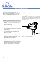
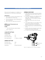
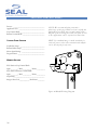
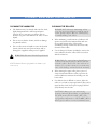
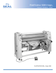
Image® 410 Laminator Owners Manual Owner’s Operation Manual Image ® 410 Laminator TABLE OF CONTENTS TABLE OF CONTENTS ...................................................................................................................................................................2 INTRODUCTION................................................................................................................................................................................3 WORKSPACE / ELECTRICAL REQUIREMENTS .............................................................................................................4 ENVIRONMENT CONDITIONS................................................................................................................................................5 UNPACKING, SET-UP AND INSTALLATION....................................................................................................................6 IMPORTANT SAFEGUARDS.........................................................................................................................................................8 SAFETY FEATURES ...........................................................................................................................................................................9 LAMINATOR FEATURES................................................................................................................................................................10 CONTROL PANEL .............................................................................................................................................................................11 PRESET PROGRAMS..........................................................................................................................................................................13 CHECKING OPERATION..............................................................................................................................................................14 SET-UP AND OPERATION............................................................................................................................................................15 WEBBING FILMS WITHOUT A RELEASE LINER............................................................................................................17 WEBBING FILMS WITH A RELEASE LINER.......................................................................................................................18 DECALING (HEAT-ACTIVATED).............................................................................................................................................19 DECALING (PRESSURE- SENSITIVE).....................................................................................................................................20 MOUNTING...........................................................................................................................................................................................21 ONE STEP MOUNTING AND LAMINATING...................................................................................................................22 ENCAPSULATING..............................................................................................................................................................................23 PRE-COATING BOARDS................................................................................................................................................................24 APPLYING AN OVERLAMINATE.............................................................................................................................................25 PROCESS CONTROL SHEET........................................................................................................................................................26 CLEANING / MAINTAINING YOUR LAMINATOR......................................................................................................27 PERIODIC MAINTENANCE SHEET........................................................................................................................................28 ERROR CODES.....................................................................................................................................................................................29 TROUBLESHOOTING GUIDE....................................................................................................................................................30 GLOSSARY OF TERMS.....................................................................................................................................................................32 SPARE PARTS LIST..............................................................................................................................................................................33 TECHNICAL SPECIFICATIONS..................................................................................................................................................34 LIMITED WARRANTY......................................................................................................................................................................35 2 INTRODUCTION Thank you for purchasing a SEAL ® Image® 410 Laminator. We have designed the SEAL Image 410 to give you years of reliable service. The Image 410 brings a new level of simplicity and ease of use to image finishing. As you become familiar with your laminator, you will appreciate the high quality of its production and the excellence in its engineering design. By following the guidelines for proper care and use of the SEAL Image 410, you can depend on many years of trouble-free profitability from your investment. The purpose of this manual is to outline the materials and process when using SEAL Brands supplies with your laminator to create signs, displays, and flexible graphics with professional results. The manual includes instructions of various laminating procedures, which are meant to give you comprehensive information needed for the efficient use of your laminator. Please read and fully understand the entire manual before proceeding to use your laminator. STATEMENT OF INTENDED USE Your SEAL Image 410 Laminator meets the CE Machinery Safety Directive and is ETL approved. The SEAL Image 410 laminator has been designed to be used with SEAL Brands materials. When used with these products, you are able to mount, mount and laminate, and encapsulate prints in one step. Your laminator has been tested with SEAL Brands supplies and we recommend using these products for professional results. WARNING! This laminator is designed for mounting and laminating. Any use other than the intended may cause damage to the laminator or physical harm to the user. WARNING! Any unauthorized changes or modifications to this unit without our prior written approval will void the user’s warranty and will transfer health and safety obligations to the user. LIABILITY STATEMENT The details given in this manual are based on the most recent information available to us. They may be subject to change in the future. We retain the right to make changes to the construction or the design of our products without accepting any responsibility for modifying earlier versions previously delivered. CAUTION! Please pay attention to all passages marked this way. This information is vital to preventing user injury and/or damage to the unit. Failure to follow this information could void the user’s warranties and transfer all safety obligations to the user. 3 WORKSPACE / ELECTRICAL REQUIREMENTS • Keep the area around your laminator clear with adequate space around it so you can feed, receive and trim mounted and/or laminated images. CONNECTING YOUR LAMINATOR An area 11’ x 11’ (3.4m x 3.4m) is the smallest area recommended. We recommend a room size of 20’x 18’ (6.1m x 5.49m) to accommodate a laminator and 2 (4’ x 8’) tables on castors for finishing/layout work. This area is required for loading and unloading rolls of material onto the unwind shafts and feeding and receiving the maximum mounting board lengths into the laminator correctly. NOTE: Maximum board lengths are up to 12 feet long. • The work area should be level, flat, and well lit. IMPORTANT! SEAL Graphics recommends that a licensed electrician in accordance with electrical codes in your area install your mains power or the warranty will be void. Specifications subject to change without notice. We recommend the installation of a Ground Fault Interrupter (GFI) circuit breaker if operating the laminator near water or in an area of high humidity. 26" /66 cm Un win dS haf t Minimum Room Width =11 feet / 3.4 meter 43" /11 0c m • Connect the laminator in accordance with the details given on the identification plate (Serial Number Label) attached to the left stand leg of the laminator. Refer also to the Technical Specifications page for more information. Rol ls o fM edi a • Maximum board length Maximum board length 30"/76 cm Minimum Room Length = 11 feet / 3.4 meter Figure 1. Workspace Area Diagram 4 ENVIRONMENT CONDITIONS The following environmental conditions are ideal for the best operation of the laminator. AMBIENT TEMPERATURE The best temperature for the SEAL ® Image® 410 is between 50°F and 86°F (16°C and 30°C). SURROUNDINGS Install the laminator in surroundings that are as clean and dust free as possible in order to obtain the highest quality output. The background dust level must not exceed that found in a typical office/computer room environment. Do not expose the laminator to direct sunlight as output quality may be affected. The materials that are used on this laminator can have an electrostatic charge and will attract dust, adversely affecting the output. RELATIVE HUMIDITY POWER SUPPLY For best results, the ambient relative humidity for the SEAL Image 410 should be between 70-90% noncondensing. Too much humidity will affect the prints being laminated causing problems with film adhesion. Connect the laminator in accordance with the details given on the Serial Number Label attached to the left stand leg of the laminator. Refer also to the Technical Specifications page for more information. WATER AND MOISTURE If the laminator is installed in a damp room or near water, the electrical power supply must be in accordance with the standards prevailing in the country concerned. Once power is connected to your laminator, press the Main Power Stand-by button on the control panel to turn the laminator ON. If you have no displays, refer to the “Troubleshooting” page for problem solving information. Identification Plate Figure 2. Serial Number Label Location Diagram 5 UNPACKING, SET-UP AND INSTALLATION ONLY SKILLED PERSONNEL SHOULD PERFORM INSTALLATION. READ AND COMPLY WITH ALL WARNINGS AND FOLLOW THE PROPER INSTALLATION PROCEDURES AND SAFETY GUIDELINES. • Take into account the weight of the laminator (570lb./258 kg shipping weight) when moving. Use equipment with which the weight can be safely lifted. The laminator is transported on a wooden pallet (skid). If your laminator is still on its skid, you can move it with a forklift to put it near its place of use. IMPORTANT! Set the forks of the forklift to the maximum lifting width of the laminator, so the laminator’s center of gravity is central between the forks. • NOTE: We recommend that you save the transport bolts, nuts and plates of the shipping crate for any major moves that you plan to make with the laminator in the future. • Remove the transport bolts from the skid’s transport plates with an open-end wrench or adjustable wrench. Using the wrench, back the bolt up enough to clear the cabinet castors for ease in moving. • • 6 Your laminator has castors to allow for easy moving. Roll the laminator to the location it will be used. (See Workspace Area Diagram – Figure 1). Lock the castors once it is in place and remember to unlock them before moving the laminator again. Figure 3. Moving the laminator with a forklift. ACCESSORIES INCLUDED: • 2-1/2 Square Cap for Stand Legs (4) • Velcro, Black (to secure caps to stand legs) • Snitty Safety Knife • Image Roll Cleaner • Roll Cleaning Towel • Owner’s Manual UNPACKING YOUR LAMINATOR • • • • • • • • Remove the transport packing and the plastic shrink-wrap the laminator is wrapped in to avoid moisture penetration. Remove the accessory kit package from the top of the laminator, which includes the necessary tools for installation. Remove the footswitch from the top of the laminator and remove the foam wrapped around it. Place the footswitch in a position that is accessible while feeding images. Remove the protective foam wrapped around the front table. Remove the cardboard box containing the wind-up idler and remove the wind-up idler from the box. Install the Wind-up Idler into place on the front Wind-up Assemblies. Cut and remove the tie straps securing the Unwind Shafts and remove the foam wrap from the ends. • The top roller will go up automatically when power is connected. • Remove the blocks placed between the top and bottom roller ends. • • Remove the stickers securing the protective paper on the rolls using your fingers only. Then gently pull the paper towards you to unwind off the roll. WARNING! DO NOT USE OPEN BLADES TO REMOVE THE PROTECTIVE PAPER ON THE ROLLERS. • Roller damage caused by improper use of cutting tools will void the user’s warranty. Small cuts and imperfections in the rollers greatly affect the quality of the output and roller replacement costs are expensive. LEVELING YOUR LAMINATOR • Use the open-end or adjustable wrench to turn the transport bolts down until the bolts are positioned flat against the floor. • Insert a 3’ x 1’ (91cm x 30cm) piece of foam board across the center of the laminator lengthwise between the top roller and the back table and place the level in the center on top of this foam board. • Adjust the leveling feet for each side cabinet until level. • Next, place the level sideways on the piece of foam board and adjust the leveling feet from the front to the rear of the cabinet as needed. 7 IMPORTANT SAFEGUARDS SAFETY SYMBOLS USED ON THE LAMINATOR IMPORTANT! Read and make sure you understand these safety and operating guidelines. WARNING! Make sure the power disconnect located on the left side stand leg is turned to the OFF position before removing the side plate covers for any maintenance. IMPORTANT! Do not place heavy objects on the power supply cord. ROTATING PARTS: RISK OF INJURY PREVENTATIVE MEASURES: CAUTION! Failure to use caution near rotating rollers could result in physical injury. Be careful that items such as loose clothing, long hair and jewelry do not become entangled in rotating parts. The laminator is equipped with photoelectric eyes to prevent contact with the rotating rollers. Make sure that these safety provisions are always in operation/installed. Do not feed objects such as staples, paper clips and rough or abrasive materials through the laminating rollers. Keep all objects, such as tools, rulers, pens, markers or knives away from the roller opening. Refrain from leaving such items on the front table to prevent them from accidentally being fed into the rollers. IMPORTANT! The laminator operation will cease immediately when the photo electric eyes, set directly in the path of the front of the rollers, are blocked. On Domestic version laminators, the foot switch overrides the photoelectric eyes. When the photo eye is blocked, a BUZZER sounds, warning of close proximity to the nip. Use care to keep hands clear of the rollers while using the foot switch to prevent possible injury. IMPORTANT! NEVER cut or slice directly on the rollers as any cuts or gouges will destroy them. ALWAYS use cutters with enclosed blades to prevent cutting the rollers and to avoid extensive replacement costs. HOT SURFACE: RISK OF INJURY ON CONTACT IMPORTANT! The main roller should be together and turning while heating up to prevent uneven hot spots on the roller. A stationary roller will develop concentrated heat in one area, which will damage the roller. Pivot the front table away from the heated roller when not in use to prevent possible warping and voiding the warranty replacement. CAUTION! The laminator contains heated rollers, which may reach temperatures of 250°F (121°C). There is a danger of burns if the heated roller is touched during use. Even after switching off the laminator, the roller remains hot for a long time. WARNING! Always adjust the nip setting to create a gap between the laminating rollers to prevent flat spots from developing when the laminator is not in use. Flat spots will affect the quality of the output and void the warranty replacement. SERVICING AND REPLACEMENT PARTS ELECTRICAL PARTS – DANGER OF BEING INJURED BY ELECTRICITY WARNING! Do not remove the side plate covers because of the risk of being injured by voltage. Only authorized maintenance and service technicians or safety personnel should do this for mechanical upkeep or repair. 8 Service and maintenance must be performed fully in accordance with the instructions. Servicing by any unauthorized technician voids the warranty. The service technician must use replacement parts specified by SEAL ® Graphics. Service Technicians must perform safety checks after completing any service or repairs to the laminator. SAFETY FEATURES The SEAL ® Image® 410 Laminator is designed with safety and protective devices with the user’s safety of utmost consideration. However, following safe operating guidelines is still the responsibility of the operator. COVERED FOOT SWITCH: POWER DISCONNECT SWITCH: WARNING! On Domestic version laminators the foot switch overrides the photoelectric eyes. When the photo eye is blocked, a Flashing Light and a BUZZER sounds, warning of close proximity to the nip. Use care to keep hands clear of the rollers while using the foot switch to prevent possible injury. Located on the left stand leg (facing front of laminator), it automatically shuts the laminator power off when the power disconnect switch is turned to the OFF position. WARNING! Authorized service technicians must disconnect the power by using the power disconnect switch before any servicing. SIDE PLATE COVERS: The Side Plate Covers house the inner workings of the laminator that maintenance or safety personnel can open only with an Allen wrench. WARNING! Use of the inside of the Side Plate Covers for storage may cause possible personal injury and/or damage to the inner workings and will void the warranty. HAND-OPERATED EMERGENCY STOP BUTTONS: Emergency Stop buttons are located on the top of each of the side plate covers for easy access. Once pressed, they immediately cease the laminator’s operation and raise the top roller. Use these only in the case of an emergency or you may damage an image during a process. NOTE: Once pressed, these buttons lock and must be turned clockwise to reset. After resetting the Emergency Stop button, you must turn the main power and the heaters back on (if being used), and press the Motor Button ON to begin processing again. NOTE: If the Emergency Stop is depressed, the machine will default to Program 1 upon restart. The foot switch allows for complete user control when initially feeding an image into the nip or for feeding a delicate image through the rollers. The cover prevents accidentally stepping on the foot switch and starting the laminator. PHOTO ELECTRIC SAFETY EYES: A light beam path set directly in front of the laminating roller opening prevents foreign objects from passing between the rollers. (The eyes are set for use at the factory and checked by the service representative.) If the photo-eye is blocked when lowering the top roller, there will be an audible alarm and the top roller will not move down. To allow the top roller to continue movement, the operator must clear the nip and then press the Nip Adjustment Button DOWN arrow. The roller will proceed to lower to the desired setting. NOTE! This function can only be overridden by using the footswitch. REVERSE BUTTON: The Reverse Button allows the rollers to be reversed if there is a wrap around the enclosed pull rollers. The Reverse Mode is operational when the motor is Off and the footswitch is used. WARNING! Keep hands clear of the pull rollers’ nip when using the Reverse Button. This button can only be used in conjunction with the footswitch and while operating at a slow speed of 1 fpm (.3mpm). The speed cannot be adjusted. 9 LAMINATOR FEATURES 2 3 5 4 6 7 1 3 9 8 4 Figure 4. Laminator Features 1. • 2. • 3. • 4. • 5. • 10 Digital Touch Pad Control Panel with LED indicators It allows the operator to use 9 preset heat and motor speed settings to match film applications. The operator can also customize these settings. Nip Motor driven roller height adjustment Allows for accurate roller nip setting with no need for an air compressor. Adjusts for the thickness of the material to be processed. Nip Indicator Lights indicate which nip setting the rolls are currently set at. Emergency Stop Buttons (2) Located on top of each side plate cover which immediately ceases the laminator’s operation and raises the top roller. Swing-out Auto-grip Unwind Shafts (2) Easy loading and positioning of materials. Suitable for rolls wound onto a 3-inch ID core. Integral Braking System A simple braking system with a Knurled Collar provides the means of adjusting the brake tension for the films and images. Fitted on both the autogrip unwind shafts. 6. • 7. • High release Silicone Coating Covered Rollers Prevents adhesive build-up and allows for easier cleaning Automatic Wind-up Idler Removable idler for winding up the release liner, finished images or other laminate material. Located on the top front of the laminator. Use with 3-inch ID spare cores. 8. Print Guide In-feed Table • Table with print guide for flat, wrinkle-free feeding of digital prints. Pivots down to allow for easier webbing. Feeding images under the print guide, directly into the nip, prevents the images from lifting up and interupting the photoelectric eyes. 9. Flashing Warning Light • When the using the footswitch, if the photo eye is blocked, this Flashing Light and a BUZZER sounds, warning of close proximity to the nip. *** Covered Foot Switch • Allows for complete user control when initially feeding in an image. *** Electric Heating Elements • Provide for rapid, even heating to 250° F (121°C). CONTROL PANEL 1. Nip Adjustment Button: Press the UP arrow once to raise one setting. Press and hold to raise multiple settings. Press the DOWN arrow once to lower one setting. Press and hold to lower multiple settings. 2. Nip Indicator Lights (LEDs): Indicates which nip setting the rolls are currently set at. 3. Main Power On/Off (Stand-by) Button: Press this button to turn ON or OFF (put in Stand-by) the laminator. In Standby, the laminator power is still on, but all functions are disabled. If an Emergency Stop is pressed this button must be pressed to restart the laminator. The corresponding LED is lit when the power is ON. WARNING! Even when the power is Off, the laminator is in Stand-by. Authorized Service Technicians must unplug the laminator before any servicing. 4. Program Enter Button: This button has two functions. • Function A: Loading Preset Program. Press and release to load shown program. • Function B. Programming a New Preset. First, select the desired program (1-9) you are changing the settings for. Next, set the heat and motor speeds to how you want the program to recall them. Then, push and hold the Program Enter button. The display will go blank (approximately three seconds), and then the program will appear on the display. Release the button. NOTE: After a program has been loaded, the operator can still change heat and speed settings with their respective up and down arrows. 5. Program Select Button: Press Up or Down arrow once to see current program settings. (Speed and Temperature Readouts). Press and hold Up or Down arrow to raise or lower preset program number. 1 2 3 4 5 6 7 8 9 10 11 12 13 14 15 16 Figure 5. Control Panel Diagram 6. Program Readout: Indicates which program is currently available. 11 7. Reverse Mode Button: Reverses the direction of the roller rotation. NOTE: The Reverse Mode Button may only be used with the footswitch and when the motor is OFF. • To use the Reverse Mode: Press the Reverse Mode Button, the corresponding LED will be lit. Depress the footswitch to activate the reverse roller rotation. The Motor LED will be lit during operation. NOTE: The rollers will reverse at 1 fpm (.3mpm) and the speed cannot be adjusted. • To return to Forward Mode: Push the Reverse Mode button, while not depressing the footswitch. The Reverse Mode LED will not be lit. • Press the Motor On/Off Button, the Motor LED will be lit. 8. Motor ON/OFF Button: Press UP to start the roller rotation, the switch will be illuminated. Press the switch DOWN to stop the roller rotation. In the OFF position, the footswitch can be used for roller rotation. 9. Motor Speed Adjustment Button: Press the corresponding arrow to increase or decrease the speed. 12 10. Motor Speed Readout: Indicates speed in feet or meters per minute. 11. Top Roller Temperature ON/OFF Button: Turns ON/OFF the top roller heater. The corresponding LED is lit when the heater is ON. 12. Top Roller Temperature Adjust Button: Press either arrow (up or down) once to see the temperature set point. Press and hold the corresponding arrow to raise or lower the roller temperature. 13. Top Roller Temperature Readout: Displays both the set and actual temperature of the top roller. 14. Bottom Roller Temperature On/Off Button: Turns On/Off the bottom roller heater. The corresponding LED is lit when the heater is ON. 15. Bottom Roller Temperature Adjust Button: Press either arrow (up or down) once to see the temperature set point. Press and hold the corresponding arrow to raise or lower the roller temperature. 16. Bottom Roller Temperature Readout: Displays both the set and actual temperature of the bottom roller. PRESET PROGRAMS Settings provided are for optimal performance using the SEAL® Brands films listed. Purchasers should individually determine, prior to use, the suitability of each material for their specific purposes. PROGRAM 4: RIGID BACKLIT DISPLAYS Rigid Backlit Displays are created by face mounting an image to clear acrylic using an optically clear pressure sensitive adhesive. Use the laminator to coat the acrylic and mount the print. Top (Optimount®) NOTE: When using a preset program, the temperature will automatically activate. PROGRAM 1: FLEXIBLE DISPLAYS (ENCAPSULATING) Flexible displays are created by sealing a print between two layers of laminate. Top (Jet Guard Crystal Matte) ® Bottom (Jet Guard ® Gloss) Speed 200°F (95°C) 200°F (95°C) 3fpm (1mpm) PROGRAM 2: POP-UP DISPLAYS Pop-Up Displays are created by encapsulating a print between a hot laminate and a hot backing film. Top (Jet Guard® Deep Crystal) 195°F (90°C) Bottom (Stoplight 220 or 370) Speed 210°F (100°C) 3fpm (1mpm) ® PROGRAM 3: RIGID INDOOR DISPLAYS (DECALING) Rigid Indoor Displays are made by first creating a decal, by applying a laminating film over the face of the print, and a pressure sensitive adhesive to the back. Top (Jet Guard® Crystal Matte) Bottom (Print Mount®) Speed 140°F (60°C) Bottom (NA) Speed 110°F (45°C) 3fpm (1mpm) PROGRAM 5: FLOOR GRAPHICS Floor Graphics are made by first creating a decal. Apply Floor Guard, a special non-slip durable laminating film, to the face of the print and Floor Grip 1, a permanent/removable pressure sensitive adhesive, to the back. This can be done in one pass. Use a hand roller or squeegee to apply the graphic to a clean smooth floor. Top (Floor Guard®) 200°F (95°C) Bottom (Floor Grip ®) Speed 110°F (45°C) 3fpm (1mpm) PROGRAM 6: RIGID DISPLAYS Rigid Displays are created by sealing a printable laminate onto a foam board or rigid substrate. Top Bottom Speed 230°F (110°C) 110°F (45°C) 0.5-1.0fpm (0.2-0.3mpm 205°F (95°C) 110°F (45°C) 3fpm (1mpm) PROGRAM 7, 8, AND 9: OPEN Top (Film) Bottom (Film) Speed ___°F (__°C) ___°F (__°C) __fpm (__mpm) 13 CHECKING OPERATION After you are familiar with the control panel and its functions, check all operations. WARNING! If your laminator does not operate correctly, contact Technical Service immediately. CHECK THE MAIN POWER • Press the Main Power Stand-by button once and the temperature displays on the control panel should be lit. • If there is no power, refer to the Troubleshooting Page. CHECK THE EMERGENCY STOP BUTTONS • Press one of the Emergency Stop Buttons and the laminator will shut down. • • • Rotate the Emergency Stop Button clockwise to reset. Reset the Main Power Stand-by button (press once). The Power Indicator Light should be lit. Repeat this procedure with both Emergency Stop Buttons. CHECKING THE ROLLERS Your laminator has Nip Motor driven roller height adjustment for a smooth, flat finish. Correct adjustment of the pressure rollers’ height is essential for safe and proper operation. Check this prior to every use. Check the vertical movement of the top rollers as follows: • Press the Nip Adjustment UP arrow button once. The top roller should rise smoothly and evenly on both ends. • Press the Nip Adjustment DOWN arrow button once. The top roller should lower smoothly and evenly on both ends. IMPORTANT: The silicone covering of the rollers is soft. Do not scratch the surface with a sharp object or fingernail. 14 CHECK THE TEMPERATURE CONTROLS • Press the Top Temperature On/Off Button once. The Top Temperature Indicator Light should be lit. • The corresponding temperature control readout will display the ambient temperature. • Press the Top Roller Temperature Adjust Button UP arrow once to see the temperature set point. • Press and hold the Top Roller Temperature Adjust Button UP arrow to increase the temperature set point. Watch the readout for 5 minutes to verify that the temperature increases. • Press and hold the Top Roller Temperature Adjust Button DOWN arrow to decrease the temperature set point. Watch the readout for 5 minutes to verify that the temperature decreases. • Press the Top Temperature On/Off Button once. The Top Temperature Indicator Light should not be lit. Repeat this procedure for the Bottom Temperature. • CHECK THE MOTOR AND FOOTSWITCH • Push the Motor ON/OFF button once, the motor indicator light will be illuminated and the rollers should rotate in the forward direction. • Press and hold the Motor Speed Adjustment Button UP arrow and the speed of the rollers and display readout should increase. • • • • Press and hold the Motor Speed Adjustment Button DOWN arrow and the speed of the rollers and display readout should decrease. Press the Motor ON/OFF button once and the rollers should stop rotating. Press the footswitch and the rollers should rotate. Adjust the Motor Speed by pressing the respective arrow of the Motor Speed Adjustment Button while using the footswitch to verify that the speed increases and decreases. S E T -UP AND OPERATION TEMPERATURE SETTINGS HOW TO SET THE ROLLER NIP • Select the film(s) that you will use on the top (and bottom) of the images. • First, determine the thickness of the board that you will use for mounting. • Check which temperature setting is recommended for your SEAL ® Brands material (see literature enclosed in your material box). • Adjust the nip setting by pressing the UP or DOWN arrow until the desired measurement corresponds with the thickness of board being used. • Refer to the Control Panel Diagram for information on setting the temperature. • Lower the top roller once the nip setting is adjusted. NOTE: If a process requires heat, turn ON the heaters approximately 30 minutes before use to ensure that the rollers are at the correct operating temperature. WARNING! Too much pressure can crush the board being used and even damage the top and bottom rollers. Normally, a press of .025” (0.6mm) is sufficient. IMPORTANT! The main roller should be down and turning to prevent uneven hot spots on the roller. A stationary heated roller will develop concentrated heat in one area, which will damage the roller. ROLLER NIP SETTINGS Whenever you mount onto a board, etc., it is important to adjust the rollers to create a gap nearly equal to the thickness of the board being used. This is done so that anything passing between the rollers will receive the right amount of pressure. Equivalent Press Measurements Inches Metric (mm) Decimal MAX 28.6 mm 1.125 1 25 mm 1.000 3/4 19 mm 0.75 1/2 13 mm 0.50 3/8 10 mm 0.375 1/4 6 mm 0.25 3/16 5 mm 0.1825 1/8 4 mm 0.125 1/16 2 mm 0.0625 0 0 0 Figure 6. Nip Adjustment Settings BASIC STEPS TO FEEDING IMAGES • • • NOTE: For good results, the process requires that the images be fed through correctly. Make sure the leading edge of each image is flat all the way across or any wrinkles or creases in the image will show when laminated – perhaps even magnified. A straight leading edge will aid in feeding in the image. Feed the image into the laminator ensuring that the leading edge is parallel to the roller. NOTE: Do not stop the motor while an image is being finished as this can cause marks in the output. 15 IMPORTANT! The position of all films, boards, rolls of media and cardboard cores for wind-ups must be set central in the laminator to ensure optimum quality and correct tracking. SETTING THE UNWIND BRAKE TENSION • • • IMPORTANT! The brake tension greatly affects the smooth flow of the laminating film. Turning the unwind brake in a counter-clockwise direction increases the braking tension applied on the laminate. Turning the unwind brake in a clockwise direction decreases the braking tension. The best setting for the unwind brake tension is determined by the materials you are using and is learned through experience. Laminate Side Adhesive Side Figure 8. Loading Films on Unwinds Figure 7. Unwind Brake Stretch film tight and align edges. LOADING A ROLL OF MATERIAL • • • IMPORTANT! Make sure to fully release brake tension whenever changing a roll of film. Swing out the desired unwind shaft towards you and slide a roll of material onto the unwind shaft. Ensure that the rubber blocking cords are on the top and bottom for easy loading. IMPORTANT! Make certain that you place the roll of film on the unwind shaft so that the material will feed with the adhesive side facing away from the rollers. Press the unwind shaft firmly back into the receiver to prevent tension and tracking problems. Center the films on the unwind shafts. Measure the distance from the face of the cabinet and the film edges (not the cores) and adjust until they are equal. Figure 9. Aligning Films on Unwinds • • • 16 TIP! For alignment accuracy, pull a length of film backward off the top unwind shaft until it drapes over the film on the bottom unwind shaft. Make sure the edges of both films line up. Now secure the films on the shafts by gripping the shafts with one hand while rotating the rolls of material with the other hand in the direction it will be pulled off the unwind shafts. The rubber blocking cords will catch on the inside of the material core and hold the material secure on the shaft. If material needs to be rotated, turn the shafts, not the rolls of film otherwise the roll of film will no longer be secure to the shaft. WEBBING FILMS WITHOUT A RELEASE LINER The following are the basic webbing procedures for webbing films without a release liner: • Select films slightly wider than the image to allow for a border without film waste. A border of 1/8” to 1/4” (3-6mm) is adequate. • Ensure the main roller’s temperatures are set according to the recommendations of the laminates being used (see literature enclosed in your material box). WARNING! The rollers should be together and turning while heating up to provide even heat distribution and prevent roller flat spots from developing. • When the film reaches the chill shoe, cut off the leader board. WARNING! Do not use open blades to cut or slice on the surface of the chill shoe. Small cuts and scratches will affect the output quality. • Using the footswitch, feed the film into the pull rollers. • Check at the rear of the laminator, making sure the film does not wrap around the enclosed pull rollers. • Raise the top roller and set the Nip Setting to ‘0’, then lower the roller again. • Return the in-feed table to its working position. • Once the laminator reaches correct operating temperature, stop the laminator and raise the top roller. • Apply light unwind brake tension gradually on both unwind shafts until there are no wrinkles in the film as it goes into the nip • Pivot the front table down for easier webbing access. • • Load and center the films on top and bottom unwind shafts with the dull adhesive side facing out and the unwind brake tension released. Run the laminator for about 3 feet (1 meter), to work out any wrinkles. If wrinkles persist, cut the film and web the laminator again. YOU ARE NOW READY TO FEED IMAGES! NOTE: Check if the film widths of the lower and upper web are the same! • TOP FILM: Pull the film down from the top unwind shaft, and place it evenly over the face of the top roller. • BOTTOM FILM: Pull the film up from the bottom unwind shaft and place it evenly over the top film draped over the face of the top roller. • The two films will then heat and stick together. • Set the Nip Setting to 1/16” (2mm) to allow for the thickness of a leader-board. • FILMS INTO NIP: Use the leader-board to push the film(s) into the main roller nip. • Lower the top roller and use the foot switch to advance the leader board through the nip. NOTE: Keep the film under tension (holding back on the film roll) to prevent the photoelectric eyes being tripped. Film Path Media Path Figure 10. Webbing films w/o Release Liners 17 WEBBING FILMS WITH A RELEASE LINER The following are the basic webbing procedures for webbing films with a release liner: • Select films slightly wider than the image to allow for a border without film waste. A border of 1/8” to 1/4” (3 - 6mm) is adequate. • Ensure the main roller’s temperatures are set according to the recommendations of the laminates being used. • Once the laminator reaches operating temperature, stop the laminator and raise the top roller. • Pivot the front table down for easier webbing access. • Load and center the films on top and bottom unwind shafts with the dull adhesive side facing out and the unwind brake tension released. NOTE: Check if the film widths of the lower and upper web are the same! • TOP FILM: (film with a release liner) Pull the film down from the top unwind shaft, and place it evenly over the face of the top roller. • RELEASE LINER: Place a spare core over the front top wind-up idler. Separate the film from the release liner. Attach the release liner to the spare core using a piece of tape. • BOTTOM FILM: Pull the film up from the bottom unwind shaft and place it evenly over the top film draped over the face of the top roller. The two films will stick together. • Set the Nip Setting to 1/16” (2mm) to allow for the thickness of a leader-board. • FILMS INTO NIP: Use the leader-board to push the film(s) into the main roller nip. • Lower the top roller and use the foot switch to advance the leader board through the nip. • NOTE: Keep the film under tension (holding back on the film roll) to prevent the photoelectric eyes being tripped. 18 • When the film reaches the chill shoe, cut off the leader board. WARNING! Do not use open blades to cut or slice on the surface of the chill shoe. Small cuts and scratches will affect the output quality. • Using the footswitch, feed the film into the pull rollers. • Check at the rear of the laminator, making sure the film does not wrap around the enclosed pull rollers. • Raise the top roller and set the Nip Setting to ‘0’, then lower the roller again. • Return the in-feed table to its working position. • Apply light unwind brake tension gradually on both unwind shafts until there are no wrinkles in the film as it goes into the nip • Run the laminator for about 3 feet (1 meter), to work out any wrinkles. If wrinkles persist, cut the film and web the laminator again. YOU ARE NOW READY TO FEED IMAGES! Film Path Media Path Release Liner Figure 11. Webbing films with Release Liners DECALING (HEAT -ACTIVATED) This process involves applying a hot film to the top and a cold backing adhesive to the bottom of the graphic. This process can be used to create self-adhesive images for mounting down onto various substrates. After performing this process, follow the Mounting Instructions in the manual to apply the decal to a substrate. It is important to follow the webbing instructions for films specific for your location. NOTE! When using Mounting Adhesive on the back of images it is best to run over the back table. Running the film through the pull rollers may cause the backing to separate from the release liner. NOTE! Web the top laminate following the basic procedures for webbing films w/o a release liner. MEDIA: INK JET, ELECTROSTATIC AND PHOTOGRAPHIC FILMS: -- -- -- Top Unwind: Heat-activated Laminate 3 – 5 Mil _____ Bottom Unwind: Pressure-sensitive mounting adhesive LAMINATOR SETTINGS CONTROL PANEL Top Roller Temp 205-215°F (96-102°C) Bottom Roller Temp OFF Motor Speed Setting 3-5 FPM (1-1.5 MPM) Film Path Media Path WEBBING SETTINGS Web Tension Top: Medium Web Tension Bottom: Light Nip Setting: ‘0’ Figure 12. Webbing for Decaling (Heat-activated films) 19 DECALING (PRESSURE- SENSITIVE) This process involves applying a cold pressure-sensitive over-laminate to the top and a cold pressure-sensitive mounting adhesive to the bottom of a graphic. If desired, set the top roller’s temperature to 120° F (49° C). Using heat-assist may improve the adhesive bonding of the laminate. This process can be used to create self-adhesive images for mounting down onto various substrates. After performing this process, follow the Mounting Instructions in the manual to apply the decal to a substrate. It is important to follow the webbing instructions for films specific for your location. NOTE: When using Mounting Adhesive on the back of images it is best to run over the back table. Running the film through the pull rollers may cause the backing to separate from the release liner. NOTE! Web the top laminate following the basic procedures for webbing films with a release liner. MEDIA: INK JET, ELECTROSTATIC, AND PHOTOGRAPHIC FILMS: -- -- -- Top Unwind: Pressure-sensitive over-laminate ____ Bottom Unwind: Pressure-sensitive mounting adhesive LAMINATOR SETTINGS CONTROL PANEL Top Roller Temp: OFF or Heat-assist Bottom Roller Temp: OFF Motor Speed Setting: 3-5 FPM (1-1.5 MPM) Film Path Media Path Release Liner Figure 13. Webbing for Decaling (Pressuresensitive films) WEBBING SETTINGS Web Tension Top: Light Web Tension Bottom: Light Nip Setting: ‘0’ 20 MOUNTING This process involves mounting previously prepared decals onto a substrate. No films or adhesives are required for this process. • TO MOUNT DECALS ONTO A SUBSTRATE • • Place the mounting board on a flat surface. • Lay your image face down on the mounting board and expose approximately 1” (25 mm) of the adhesive by peeling back the release liner along one of the edges. • Fold the release liner back making an even crease. • Turn the image over and carefully position the exposed adhesive edge of the image squarely onto the board. • Once positioned correctly, press the exposed adhesive edge of the image firmly down onto the board from the center toward the edges to ensure a smooth surface. This is the edge that will be fed into the rollers first. NOTE: Take care that the rollers do not grab the liner. Push the edge of the board into the rollers and depress the foot switch until the board and image are just caught by the nip. • Flip the un-tacked portion of the image over the top roller with one hand so that the release liner can be peeled off the image with the other hand. • Depress the foot switch to feed the board through the rollers. If the board is accidentally sent in too far at first, the release liner will get caught and will be impossible to pull back. In this case, stop and use the Reverse Button until the liner can be pulled away. IMPORTANT! The Reverse Button can only be used in conjunction with the footswitch and only at a slow speed. WARNING! Keep hands clear of the pull rollers while using the Reverse Button. • The image must be held against the roller while the board feeds through to prevent wrinkles. NOTE: Take care that the release liner does not trip the photoelectric eye safety system. • As the process becomes more familiar, the speed of the laminator may be increased to make the process more efficient. • Remove the mounted image from the rear of the laminator, trim it to size and display it. IMPORTANT! Ensure that the Nip setting corresponds to the board thickness. • At this point, continuous run can be selected by pressing the Motor switch ON. IMPORTANT! Because the foot switch overrides the photo eye, be sure to keep your hands clear of the rollers to prevent injury. Substrate Decal Release Liner Figure 14. Mounting a Decal onto a Substrate 21 ONE STEP MOUNTING AND LAMINATING This process allows you to decal and mount in one step by using a mounting board with heat activated adhesive on one side MEDIA: INK JET, ELECTROSTATIC, AND PHOTOGRAPHIC FILMS: WEBBING PROCEDURE IMPORTANT! Ensure that the Nip setting corresponds to the board thickness. • Pull the film down from the top unwind shaft, and place it evenly over the face of the top roller. • Use a piece of leader board to hold the laminate under the top roller. When using this process a leader board or your product must be in the nip. This will prevent adhesive from coating the bottom main roll. • Run a sample piece of foam board without an image. Check for adhesion, wrinkles, and bubbles. Adjust your heat and brake tension accordingly. • A leader board should be in the nip. Place an image on your mounting board, and press it against the leader board. -- -- -- Top Unwind: Pressure-sensitive over-laminate ____ Bottom Unwind: Heat-activated Laminate 3-5 Mil (Optional) LAMINATOR SETTINGS CONTROL PANEL Top Roller Temp: 225-230°F (96-110°C) Bottom Roller Temp: Optional** Motor Speed Setting: 3-5 FPM (1-1.5 MPM) NOTE: If you are mounting more than one image, send them through consecutively. Web Tension Top: Light Web Tension Bottom: Light NOTE: Follow the last board with the leader-board again to allow the final board to clear the laminating rollers and then stop the motor and raise the top roller. Nip Setting: Substrate Determined WEBBING SETTINGS NOTE: For thick laminates and images, run at a slower speed. This will allow substrate adhesives to activate properly. **OPTIONAL: Adding a heat-activated laminate to the backside of the board will prevent the board from warping over an extended period of time. Heat activated substrate Film Path Media Figure 15. One-Step Mounting and Laminating 22 ENCAPSULATING This process involves completely sealing an image between two films. It is important to follow the webbing instructions for films specific for your location. MEDIA: INK JET, ELECTROSTATIC, AND PHOTOGRAPHIC NOTE! Web the top laminate following the basic procedures for webbing films w/o a release liner. FILMS: -- -- -- Top Unwind: Heat-activated Laminate 3 – 5 Mil ____ Bott. Unwind: Heat-activated Laminate 3 – 5 Mil LAMINATOR SETTINGS CONTROL PANEL Top Roller Temp: 205-215°F (96-102°C) Bottom Roller Temp: 205-215°F (96-102°C) Motor Speed Setting: 3-5 FPM (1-1.5 MPM) Film Path Media Path WEBBING SETTINGS Web Tension Top: Medium Web Tension Bottom: Medium Nip Setting: ‘0’ Figure 16. Webbing for Encapsulating 23 P R E -COATING BOARDS This process is used to coat substrates with a selfadhesive coating onto which images can be mounted. Images can then be mounted on the substrate. This same process is used to create a sled. NOTE: When coating boards, ensure that the next board to be coated follows the previous board without any gaps. PREPARATION: NOTE: Follow the last board being coated with the leader-board again to allow the final board to clear the laminating rollers and then stop the motor and raise the top roller. IMPORTANT! Ensure that the Nip settings of the rollers correspond to the board thickness. • If desired, set the top roller’s temperature to 120° F (49° C). Using heat assist may improve the adhesive bonding of the laminate. • The bottom roller temperature is OFF. • Load the roll of pressure sensitive adhesive onto the top unwind shaft of the laminator with the exposed adhesive facing out. • Use a leader-board of the same thickness as the boards to be coated. • Pull the adhesive down from the top unwind shaft and place evenly across the face of both rollers. • Press the foot switch and using the leader -board, push the adhesive into the roller nip • Release the foot switch when the rear edge of the leader-board is almost leaving the roller nip. • Position the board to be coated into the nip, behind the leader board and choose a speed setting. Press the motor switch ON or use the footswitch to process the board. 24 Substrate Adhesive Figure 17. Pre-Coating Boards APPLYING AN OVERLAMINATE This process involves applying an over laminate to an image with the use of a sled or pre-coated substrate. PREPARATION: • Set your nip in accordance with the thickness of the pre-coated board you will be using. • Load a roll of pressure sensitive laminating film on the top unwind shaft. • Do not remove the release liner from the sled. WEBBING PROCEDURE • Pull the film down from the top unwind. Separate the film from the release liner and lay the film over the top roller. • Connect the release liner to the windup tube with a piece of tape. Attaching the release liner to a cardboard core (over the windup tube) will allow for easier cleanup. • Pull the film evenly across the face of the main rollers. • MEDIA: INK JET, ELECTROSTATIC, AND PHOTOGRAPHIC • FILMS: -- -- -- Top Unwind: Pressure-sensitive Laminate ____ Bott. Unwind: NA • • Feed a leader board that is the same thickness as the sled, into the nip. Make sure that the film is adhered to the release liner on the leader board. Place an image face up on a sled and send it through the nip. When the sled comes through, place another leader board between the nips to hold the film. You may now cut the image away from the sled. LAMINATOR SETTINGS CONTROL PANEL Top Roller Temp: Off Bottom Roller Temp: Off Motor Speed Setting: 3-5 FPM (1-1.5 MPM) WEBBING SETTINGS Web Tension Top: Light Web Tension Bottom: NA Nip Setting: Substrate Determined Sled Pressure Sensitive Film Media Release Liner Figure 18. Applying an Over-laminate Diagram 25 PROCESS CONTROL SHEET Process: _________________________________ Application Use: ___________________________ Top Unwind Shaft:__________________________ Bottom Unwind Shaft: _______________________ CONTROL PANEL SETTINGS Top Roller Temp: __________________________ Bottom Roller Temp: ________________________ Motor Speed Setting: ________________________ Program Preset ____________________________ NOTE: We recommend that you make a photocopy of this page. With each successfully run application, record the process and settings and a diagram of the webbing procedure. Keep the record so the application can be repeated at a later date. HINT: If a standard image is made available for each new process then sales materials and samples can be developed for reference. WEBBING SETTINGS Web Tension Top Unwind Shaft: Light ________/ Med. _________/ Heavy _________ Web Tension Bottom Unwind Shaft: Light ________/ Med. _________/ Heavy _________ Nip Setting: ________ _______________________ Images: Sheet Fed ___________/ Roll Easel _______ Figure 19. Blank Webbing Diagram 26 CLEANING / MAINTAINING YOUR LAMINATOR CLEANING THE LAMINATOR • The laminator may be cleaned with a lint-free cloth, lightly dampened with a mild soap and water solution. Do not use spray-on cleaners. Do not immerse any part of the laminator in water or other liquids. • Do not use an abrasive cleaner, which can damage the painted surfaces. • Do not allow water or liquids to enter the electrical circuits, which may cause personal injury and/or damage the equipment when power is applied. CLEANING THE ROLLERS IMPORTANT! Clean the laminating rollers every day to prevent adhesive build-up and to ensure quality output. Adhesive build up may eventually damage the rollers. • When laminating, a small amount of adhesive will squeeze out between the laminate films and onto the top and bottom rollers. This residue accumulates through normal use and can be easily cleaned off the rollers. • Use the Image roll-cleaner (included) to remove the excess adhesive from the rollers. This is best done with the rollers hot. WARNING! Electrical Shock Hazard inside! WARNING! Use only an Image Roll Cleaner or a cotton cloth and Isopropyl Alcohol (IPA) to clean the rollers. Do not use other solvents or cleaners. Use of other cleaners or solvents may cause roller damage and will void the warranty. Call Technical Service for further assistance (see rear cover). • When cleaning the upper roller, place a piece of scrap foam board under the roller to prevent the removed adhesive remnants from falling onto the lower roller. • For adhesive that is difficult to remove, allow the rollers to cool and use isopropyl alcohol (IPA) and a clean, lint-free cloth. Never pour isopropyl alcohol (IPA) directly onto the unit. CAUTION! Always use care when using Isopropyl Alcohol (IPA)! IPA is very flammable. The flash point of IPA is 51.8°F (11°C). The self-ignition temperature is 752°F (400°C). Wear rubber gloves and use in a well-ventilated area. 27 PERIODIC MAINTENANCE SHEET CHAIN T ENSION ADJUSTMENT / OIL CHAIN ** SAFETY CHECK AFTER SERVICING NOTE: Enter dates of service and initials of service personnel. We recommend that you make a photocopy of this page, tape it to the inside of the Side Plate Cover and use this to record dates that authorized safety or maintenance personnel perform these laminator maintenance procedures. Proper maintenance of your laminator ensures receiving many years of profit from your investment. * Use only replacement parts specified by SEAL Graphics. ** Use lightweight household oil to oil the chain approximately every three months. Call Technical Service for assistance (see the rear cover). 28 ERROR CODES THE FOLLOWING DESCRIBES THE DETAILS OF THE ERROR CODES: • The machine shuts down and the display starts blinking. • This means that the software has detected an error in the system. • The numbers on the displays tell you what error has occurred. • • The speed display will show the error level. The top temperature display will show the error data. • • These displays are used to find the problem. The bottom temperature display shows the current running program number. The first time an error occurs on your machine, reset your power by depressing and resetting the Emergency stop button. • • If the error occurs again, see the chart. • The chart defines some of the problems that may have caused the error. NOTE! If you cannot define the problem, contact your Technical Service representative for technical assistance (see rear cover). NOTE! After an error has shut down the system, the power must be turned off for 10 seconds, using the Emergency stop button. After 10 seconds, turn the power on to restore the system. WARNING! Authorized service technicians must disconnect the power by using the power disconnect before servicing. Speed Display Top Temp Display Problem Error Level 1.0 Error Data 1 The photo-eye has failed. Error Level 1.0 Error Data 5 The digital I/O (DIO) card is defective. Error Level 2.0 Error Data 0 Reset. If error occurs again, the digital I/O (DIO) card is defective. Error Level 2.1 Error Data 1 The Solid State Relay for the top main roll heater is defective. Error Level 2.1 Error Data 2 The Solid State Relay for the bottom main roll heater is defective. Error Level 2.1 Error Data 3 If the rollers are hot, the Digital I/O (DIO) card has failed. If the rollers are cold, The Analog Card has failed. Error Level 2.2 Error Data 1 The top thermocouple is defective or has a bad connection. Error Level 2.2 Error Data 2 The bottom thermocouple is defective or has a bad connection. Error Level 2.2 Error Data 3 The Analog I/O (AIO) Card is defective. Error Level 3.0 Error Data 0 The Nip Motor is locked or the encoder is defective. 29 TROUBLESHOOTING GUIDE Problem Solution The laminator will not turn on. • Check if the power cable is plugged into the mains wall outlet. • Check the Main Power Stand-by Button. The corresponding LED should be lit. • Make sure that the Emergency Stop buttons were not activated. Rotate to reset. • Unplug the laminator and check the circuit breakers under the left side plate. Check the fuse in the power supply. Only authorized safety or maintenance personnel should do this. • Make sure the Power Disconnect Switch is in the ON position. Turning the Power Disconnect Switch to the OFF position automatically shuts the laminator power off. • Make sure that the photo-eyes are not blocked. • Check that the Motor ON/OFF Button is pressed ON. The corresponding LED should be lit. • Check the motor circuit breaker under the right side plate. • Unplug the laminator and check the fuse in the motor control. Only authorized safety or maintenance personnel should do this. • Make sure the Heater Button is pressed ON. The corresponding LED should be lit. • Check the circuit breakers on the under side of the left side plate • Make sure the rollers are together (with both Nip settings set at ‘0’) and turning at a moderate speed when first heating up. Images or Prints are rippling or jumping as they are fed into the nip. • Apply tension to Images or Prints as they are fed into the nip. Hold cut sheets back by hand. The film output is rippled or wavy (boat-waking) • Check that you have webbed the laminator correctly. • Improper film tension – most encapsulating films need a minimal amount of brake tension. • Run the laminator at a higher speed for photo materials or heat-sensitive prints because exposure to heat at low speeds can cause waving. • Increase the roller temperature or decrease the motor speed. • Thicker films may require increased roller pressure due to the thicker film layer. • Refer to Error Codes page for definition of problem. The motor will not run. The laminator is not heating up or shows erratic temperature readings. The film is cloudy or mottled. Machine shuts down and display screen is blinking. 30 LOCATION OF BREAKERS • 1. Motor Breaker (0.8 Amp)– Located under the Right side plate. • 2. Control Power (2 Amp) – Located under the Left side plate. • 3. Top Heater (8 Amp) – Located under the Left side plate. • 4. Bottom Heater (8 Amp) – Located under the Left side plate. • 5. Common (16 Amp) for Domestic only – Located under the Left side plate. NOTE: All breakers are visible and can be reset, from the outside of the laminator. 4 3 5 2 1 VIEW: Under side of Left Side Plate VIEW: Under side of Right Side Plate Figure 20. Breaker Location Diagram TECHNICAL SERVICE For technical assistance, please contact your Technical Service representative (see rear cover). When calling for Technical Service please have the Laminator Serial Number (listed on the Identification Plate) available. The Laminator Serial Number is located on the left stand leg of the laminator. 31 GLOSSARY OF TERMS DECAL: OUT-FEED: An image that has been laminated on top (either heatactivated or pressure-sensitive) with an adhesive backing The side of the laminator from which completed images emerge FILM: A synonym for laminate. The material used in the laminating and encapsulating process PRE-COATING: The process of coating a substrate with an adhesive mounting film onto which an image can be mounted. PRESS: HEAT-ACTIVATED FILMS: Films with an adhesive that is activated when heat is applied. Once applied to an image the adhesive forms a strong bond adhering the laminate and the image together. The amount of force in distance put on anything that passes between the top and bottom rollers. PRESSURE-SENSITIVE FILMS: The side of the laminator from which images are fed Films with an adhesive that is activated when pressure is applied, forming a bond between the protective laminate and the surface of the image. Used primarily for fast mounting applications and recommended for heatsensitive thermal and photographic prints. LEADER-BOARD: RELEASE LINER: A piece of foam board (about 4’ x 4”) used to push films into the nip. Also used for mounting or precoating boards to prevent adhesive from getting onto the rollers and sealing edges. The backing on a pressure-sensitive film or mounting adhesive. After peeling the release liner off, the adhesive layer becomes exposed. IN-FEED: SLED: M IL: Refers to the thickness of the laminate in 1/1000ths of an inch. One Mil is equal to .0254mm or 25 micron. M OUNTING: Applying an image onto some kind of foam board or substrate. NIP: The spot where the top and bottom rollers meet 32 A board that has a non-stick surface that is used when laminating one side of an image only. These can be made using a foam board coated with a self-wound pressure sensitive adhesive. The silicone release liner is not removed during coating and provides the necessary non-stick surface. SUBSTRATE: The material to which an image is mounted or affixed SPARE PARTS LIST Please contact Technical Service for replacement parts. PART DESCRIPTION PART # PART DESCRIPTION PART # Accessory Pack, 410 1162 Heating Element 148042 Bracket, Bottom Main Roll 4065 Heater Spring, Heavy duty 275215 Board, Analog IO 131014 Motor Control Isolated 154620 Board, Digital IO 131013 Motor, Drive 107400 Board, Processor 131012 Motor, Drive Bracket 511711 Cabinet Cover Left Kit 4093 Nip Drive Kit, Right –410 4070 Cabinet Cover Right Kit 4094 Nip Drive Kit, Left –410 4071 Cage Kit, Full 4144 Photo-Eye & Micro switch Kit 4072 Chain, Connecting Link 101036 Relay, Omron 166040 Chain, 35 x 111 101183 Relay Board, 410 131100 Chain Tensioner Kit 4080 Roll - Main, Bottom 691474 Chill Shoe 729470 Roll - Main, Top 691475 Circuit Breaker, 2Amp 142620 Roll - Pull, Bottom 691473 Circuit Breaker, 16Amp 142622 Roll - Pull, Top 691472 Circuit Breaker, .8Amp 142625 Solid State Relay 25A 166060 Circuit Breaker, 10Amp 142626 Sprocket, 35B36 Bottom Main Roll 113042 Clutch Drive Kit 4062 Table Assembly 4092 Clutch Idler Kit 4063 Thermocouple Kit 42, 410 4032 Collar, ½ ID, 2 pc 275400 Unwind Kit, Top 4107 Disconnect, Power 143006 Unwind Kit, Bottom 4108 Dovetail, Inner Assembly – Left 4097 Unwind Clip, 410 511001 Dovetail, Inner Assembly – Right 4098 Wind-up Tube 615470 33 TECHNICAL SPECIFICATIONS M ECHANICAL Dimensions (H x W x D) 62”w x 30”d x 47”h (157 cm x 76 cm x 119 cm) Net Weight 480 lbs. (218 kg) Shipping Weight 570 lbs. (258 kg) Roller Construction High release silicone-covered rollers PROCESS Max. Working Width 43” (110 cm) maximum Max. Roller Speed 10 fpm (3.1 mpm) Core Inner Diameter 3” (7.6 cm) Maximum Material Outside Diameter 8” (20.3 cm) Maximum Roller Opening 1.125” (2.86 cm) Maximum Board Thickness 1” (2.54 cm) Nip Settings Inch - 0, 1/16, 1/8, 3/16, 1/4, 3/8, 1/2, 3/4, 1 & Max Mm - (0, 2, 4, 5, 6, 10, 13, 19, 25 & Max) Max. Roller Temperature 250°F (121°C) ELECTRICAL REQUIREMENTS Single phase version – Domestic 120-240 V~, 2W + G, 50/60 Hz, 16A Single phase version - International 208-240 V~, 1&, 50/60 Hz, 16A Maximum Power consumption 3840 watts / 12, 065 BTU ORDER CODES SEAL ® Image® 410 Single phase – Domestic 60074 SEAL ® Image® 410 Single phase - International 60096 Each SEAL ® Image laminator has a Serial Number Label. This is located on the left stand leg when facing the front. This label indicates the model type, the electrical requirements, and the laminator serial number (important for reference if any servicing is required). 34 LIMITED WARRANTY SEAL ® Graphics warrants to the original consumer purchaser that each new SEAL ® Image® Laminator, which proves defective in materials or workmanship within the applicable warranty period, will be repaired or, at our option, replaced without charge. Effective November 1st, 2002 the applicable warranty period for New Equipment shall be one year (parts), six months (labor and rollers) from date of purchase. This warranty extends to and is enforceable by only the original consumer purchaser, and only for the period (during the applicable term), which the product remains in the possession of the original consumer purchaser. "Original consumer purchaser" means the person who first purchased the product covered by this warranty other than for purpose of resale. This warranty does not apply if it is found that at any time the equipment has not been used for its intended purpose. Effective November 1st, 2002 the applicable warranty period for Refurbished Equipment shall be ninety days (parts and labor, excluding rollers). Rollers are not covered under warranty. The applicable warranty period for Demo Equipment shall vary, not exceeding the maximum warranty period stated herein. All Demo Equipment comes with a specific warranty, which will be stated at the time of purchase. If warranty period is not detailed in writing, there is no remaining warranty. Please ask your dealer, distributor, or sales representative for details. NOTE: Used and Not Refurbished Equipment is sold on an “AS IS” basis with No Warranty. For more information regarding this warranty, please contact your distributor. WARNING! Any unauthorized changes or modifications to this unit without our prior written approval will void the user’s warranty and will transfer health and safety obligations to the user. WARNING! Changes or modifications to this unit not expressly approved by the party responsible for compliance could void the user's authority to operate the equipment NOTE: This equipment has been tested and found to comply with the limits for a class A digital device, pursuant to part 15 of the FCC rules. These limits are designed to provide reasonable protection against harmful interference when the equipment is operated in a commercial environment. This equipment generates uses and can radiate radio frequency energy and, if not installed and used in accordance with Owner’s Manual, may cause harmful interference to radio communications. Operation of this equipment in a residential area is likely to cause harmful interference in which case the user will be required to correct the interference at their own expense. ©Copyright SEAL ® Graphics 2002 All rights are reserved. No part of the document may be photocopied, reproduced, or translated to another language without the prior written consent of SEAL Graphics. The information contained in this document is subject to change without notice and should not be construed as a commitment by SEAL Graphics. SEAL Graphics assumes no responsibility for any errors that may appear in this document. Nor does it make expressed or implied warranty of any kind with regard to this material, including, but not limited to, the implied warranties of merchantability and fitness for a particular purpose. SEAL Graphics shall not be liable for incidental or consequential damages in connection with, or arising out of the furnishing, performance, or use of this document and the program material, which it describes. Trademarks Credits SEAL ® is a registered trademark of SEAL Graphics. Image® is a registered trademark of SEAL Graphics. AquaSEAL ® is a registered trademark of SEAL Graphics. ProSEAL ® is a registered trademark of SEAL Graphics. 35 SEAL BRANDS TECHNICAL SERVICE SEAL BRANDS TECHNICAL SERVICE – EUROPE AND ASIA PACIFIC (For technical assistance & service) (For technical assistance & service) Tel: 1-800-486-6502 For UK: Tel: +44 1268 722 400 Fax: 1-800-966-4554 Fax: +44 1268 729 442 or +44 870 125 5798 For NL: Tel: +31 572 345 500 Fax: +31 572 345 501 SEAL BRANDS CUSTOMER SERVICE SEAL BRANDS CUSTOMER SERVICE – EUROPE AND ASIA PACIFIC (For information and placing orders) (For information and placing orders) Tel: 1-800-257-7325 Tel: +31 572 345 500 Fax: 1-800-966-4554 Fax: +31 572 345 501 Note: SEAL Graphics recommends that your main power be installed by a licensed electrician in accordance with electrical codes in your area. The main outlet should be fused no higher than 60 Amp, Three phase – or – 100 Amp, Single phase. Specifications subject to change without notice. Seal Graphics Americas Corporation 7091 Troy Hill Drive Elkridge, MD 21075 Tel: 410-379-5400 Fax: 410-579-8960 Seal Graphics Canada 1601 Matheson Blvd. E. Unit #4 Mississauga, Ontario Canada, L4W 1H9 Tel: 905-212-9232 Fax: 905-212-9313 Seal Graphics U.K. Ltd Unit 1, 1 Watkins Close Burnt Mills Industrial Estate Basildon, Essex SS13 1BJ United Kingdom Tel: +44 1268 722 400 Fax: +44 1268 729 442 www.sealbrands.com © 2002 SEAL Graphics SEAL and Image are registered trademarks of SEAL Graphics Part #OM410-E Rev. C (11/02) 36 Seal Graphics Europe BV Kanaaldijk O.Z.3 P.O. Box 29, 8100 AA Raalte The Netherlands Tel: +31 572 345 500 Fax: +31 572 345 501 Seal Graphics Pacific Limited Unit A, 13th Floor, Block 1 Leader Industrial Centre Tsuen Wan, New Territories, Hong Kong Tel: +852 2407 3738 Fax: +852 2408 0973