1
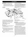
Owner's Manual
I:RAFrSMAN +
P
R
0
F
E
S
I
0
N
A
I
3 in. BELT SANDER
Electronic Variable Speed / Dustless
Double Insulated
Model No.
315.277251
Save this manual
future reference
_,
for
CAUTION"
Read and
follow all Safety Rules
and Operating Instructions before first use of
this product.
Sears,
Roebuck
972000-491
5-01
and Co., Hoffman
Estates,
IL 60179
USA
•
TableOfContents.........................................................................................................................................
2
•
WarrantyandIntroduction
..............................................................................................................................
2
•
RulesForSafeOperation...........................................................................................................................
3-5
•
ProductSpecifications
andUnpacking..........................................................................................................
6
•
Features.....................................................................................................................................................
6-7
•
Adjustments
...............................................................................................................................................
8-10
•
Operation
.................................................................................................................................................
11-13
•
Maintenance
............................................................................................................................................
14-17
•
Exploded
ViewandRepairPartsList......................................................................................................
18-19
•
PartsOrdering/ Service
...............................................................................................................................
FULL ONE YEAR WARRANTY
ON CRAFTSMAN
PROFESSIONAL
20
BELT SANDER
If this CRRFTSMRN Professional Belt Sander fails due to a defect in material or workmanship
from the date of purchase, Sears will repair it, free of charge.
within one year
WARRANTY SERVICE IS AVAILABLE BY SIMPLY RETURNING THE TOOL TO THE NEAREST SEARS
STORE OR SEARS SERVICE CENTER IN THE UNITED STATES.
This warranty gives you specific legal rights, and you may also have other rights which vary from state to state.
Sears, Roebuck and Co., Dept. 817WA, Hoffman Estates, IL 60179
Your belt sander has many features for making
sanding operations more pleasant and enjoyable.
Safety, performance and dependability have been
given top priority in the design of this sander making it
easy to maintain and operate.
_i,
CAUTION" Carefully read through this entire
owner's manual before using your new belt
sander. Pay close attention to the Rules For Safe
Operation, Warnings and Cautions. If you use
your belt sander properly and only for what it is
intended, you will enjoy years of safe, reliable
service.
GENERAL
Your Craftsman Professional Belt Sander is suitable for coarse, medium and fine sanding of wood, metals,
plastics and other materials. It is ideal when used for smoothing rough boards, chamfering, rounding edges and
many other general sanding applications. It is also an excellent tool for removing paint, varnishes, and stains. Its
balanced design makes it easy to use.
The purpose of safety symbols is to attract your attention to possible dangers. The safety symbols, and
the explanations with them, deserve your careful attention and understanding. The safety warnings do
not by themselves eliminate any danger. The instructions or warnings they give are not substitutes for
proper accident prevention measures.
SYMBOL
A
MEANING
SAFETY
ALERT
SYMBOL:
Indicates caution or warning. May be used in conjunction with other symbols or pictographs.
A
DANGER: Failure to obey a safety warning will result in serious injury to yourself or to others.
Always follow the safety precautions to reduce the risk of fire, electric shock and personal injury.
A
WARNING:
Failure to obey a safety warning can result in serious injury to yourself or to others.
Always follow the safety precautions to reduce the risk of fire, electric shock and personal injury.
A
CAUTION:
Failure to obey a safety warning may result in property damage or personal injury to
yourself or to others. Always follow the safety precautions to reduce the risk of fire, electric shock
and personal injury.
NOTE:
DOUBLE
Advises you of information or instructions vital to the operation or maintenance of the equipment.
INSULATION
Double insulation is a concept in safety, in electric
power tools which eliminates the need for the usual
three-wire grounded power cord. All exposed metal
parts are isolated from internal metal motor
components with protecting insulation. Double
insulated tools do not need to be grounded.
,_i
WARNING:
Do not attempt to operate this tool
until you have read thoroughly and understand
completely all instructions, safety rules, etc.
contained in this manual. Failure to comply can
result in accidents involving fire, electric shock,
or serious personal injury. Save owner's manual
and review frequently for continuing safe
operation, and instructing others who may use
this tool.
READ ALL INSTRUCTIONS
•
•
IMPORTANT
Servicing of a tool with double insulation requires
extreme care and knowledge of the system and
should be performed only by a qualified service
technician. For service we suggest you return the tool
to your nearest Sears Store for repair. Always use
original factory replacement parts when servicing.
KEEP WORK AREA CLEAN. Cluttered areas
and benches invite accidents.
•
AVOID DANGEROUS
ENVIRONMENT.
Don't
use power tools in damp or wet locations or
expose to rain. Keep work area well lit.
•
KEEP CHILDREN AND VISITORS AWAY. All
visitors should wear safety glasses and be kept a
safe distance from work area. Do not let visitors
contact tool or extension cord.
KNOW YOUR POWER TOOL. Read owner's
STORE IDLE TOOLS. When not in use, tools
manual carefully. Learn its applications and
limitations as well as the specific potential
hazards related to this tool.
should be stored in a dry and high or locked-up
place - out of the reach of children.
GUARD AGAINST ELECTRICAL SHOCK BY
PREVENTING BODY CONTACT WITH
GROUNDED SURFACES. For example; pipes,
radiators, ranges, refrigerator enclosures.
KEEP GUARDS IN PLACE AND IN WORKING
ORDER.
DON'T FORCE TOOL. It will do the job better
and safer at the rate for which it was designed.
USE RIGHT TOOL. Don't force small tool or
attachment to do the job of a heavy duty tool.
Don't use tool for purpose not intended - for
example - A circular saw should never be used
for cutting tree limbs or logs.
RULES
FOR SAFE OPERATION
WEAR PROPER APPAREL.
(Continued)
Do not wear loose
exceeding 100 feet is not recommended. If in
doubt, use the next heavier gage. The smaller
the gage number, the heavier the cord.
clothing or jewelry that can get caught in tool's
moving parts and cause personal injury, Rubber
gloves and nonskid footwear are recommended
when working outdoors, Wear protective hair
covering to contain long hair and keep it from
being drawn into nearby air vents,
OUTDOOR
USE EXTENSION CORDS. When
tool is used outdoors, use only extension cords
suitable for use outdoors. Outdoor approved
cords are marked with the suffix W-A, for example - SJTW-A or SJOW-A.
ALWAYS WEAR SAFETY GLASSES. Everyday
eyeglasses have only impact-resistant lenses;
they are not safety glasses,
NEVER USE THIS OR ANY POWER SANDER
FOR WET SANDING. Failure to comply can
result in electrical shock causing serious injury or
worse.
PROTECT YOUR LUNGS. Wear a face or dust
mask if the operation is dusty.
PROTECT YOUR HEARING. Wear hearing
protection during extended periods of operation.
KEEP HANDS AWAY FROM SANDING AREA.
DON'T ABUSE CORD. Never carry tool by cord
or yank it to disconnect from receptacle. Keep
cord from heat, oil, and sharp edges.
SPHERE. Normal sparking of the motor could
ignite fumes.
SECURE WORK. Use clamps or a vise to hold
work. It's safer than using your hand and it frees
both hands to operate tool.
damaged, have repaired by authorized service
facility. Stay constantly aware of cord location
and keep it well away from the sanding area.
DON'T OVERREACH. Keep proper footing and
balance at all times. Do not use while standing
on a ladder or unstable support. Secure tools
when working at elevated positions.
INSPECT EXTENSION CORDS PERIODI-
NEVER USE IN AN EXPLOSIVE ATMO-
INSPECT TOOL CORDS PERIODICALLY
and if
CALLY and replace if damaged.
KEEP HANDLES DRY, CLEAN, AND FREE
FROM OIL AND GREASE. Always use a clean
cloth when cleaning. Never use brake fluids,
gasoline, petroleum-based products, or any
strong solvents to clean your tool.
MAINTAIN TOOLS WITH CARE. Keep tools
sharp and clean for best and safest performance.
Follow instructions for lubricating and changing
accessories.
STAY ALERT AND EXERCISE CONTROL.
DISCONNECT TOOLS. When not in use, before
servicing, or when changing or adjusting sanding
belt, attachments, blades, bits, cutters, etc., all
tools should be disconnected from power supply.
Watch what you are doing and use common
sense. Do not operate tool when you are tired.
Do not rush.
REMOVE ADJUSTING KEYS AND
of the tool, a guard or other part that is damaged
should be carefully checked to determine that it
will operate properly and perform its intended
function. Check for alignment of moving parts,
binding of moving parts, breakage of parts,
mounting and any other conditions that may
affect its operation. A guard or other part that is
damaged should be properly repaired or replaced by an authorized service center.
CHECK DAMAGED PARTS. Before further use
WRENCHES. Form habit of checking to see that
keys and adjusting wrenches are removed from
tool before turning it on.
AVOID ACCIDENTAL STARTING. Don't carry
plugged-in tool with finger on switch. Be sure
switch is off when plugging in.
MAKE SURE YOUR EXTENSION CORD IS IN
GOOD CONDITION. When using an extension
cord, be sure to use one heavy enough to carry
the current your product will draw. An undersized
cord will cause a drop in line voltage resulting in
loss of power and overheating. A wire gage size
(A.W.G.) of at least 16 is recommended for an
extension cord 100 feet or less in length. A cord
DO NOT USE TOOL IF SWITCH DOES NOT
TURN IT ON AND OFF. Have defective switches
replaced by an authorized service center.
•
INSPECT FOR and remove all nails from lumber
before sanding.
RULES
FOR SAFE OPERATION
(Continued)
DO NOT operate this tool while under the
influence of drugs, alcohol, or any medication.
_i,
DO NOT USE THIS SANDER FOR OVERHEAD
SANDING. Overhead sanding could result in
dropping sander or loss of control. These situations could result in an accident resulting in
possible serious injury.
POLARIZED
• lead from lead-based paints,
• crystalline silica from bricks and cement
and other masonry products, and
PLUGS. To reduce the risk of
• arsenic and chromium from chemicallytreated lumber.
electric shock, this tool has a polarized plug (one
blade is wider than the other). This plug will fit in
a polarized outlet only one way. If the plug does
not fit fully in the outlet, reverse the plug. If it still
does not fit, contact a qualified electrician to
install the proper outlet. Do not change the plug
in any way.
Your risk from these exposures varies, depending
on how often you do this type of work. To reduce
your exposure to these chemicals, work in a well
ventilated area and work with approved safety
equipment, such as those dust masks that are
specially designed to filter out microscopic
particles.
WHEN SERVICING USE ONLY IDENTICAL
CRAFTSMAN REPLACEMENT PARTS.
SAVE THESE INSTRUCTIONS.
WARNING:
Some dust created by power
sanding, sawing, grinding, drilling, and other
construction activities contains chemicals known
to cause cancer, birth defects or other reproductive harm. Some examples of these chemicals are:
Refer to them
frequently and use them to instruct others who
may use this tool. If you loan someone this tool,
loan them these instructions also.
Look for this symbol
safety is involved.
_,
to point
out important
safety
precautions.
It means
attention!!!
Your
WARNING:
The operation of any belt sander can result in foreign objects being thrown into your eyes,
which can result in severe eye damage. Before beginning power tool operation, always wear
safety goggles or safety glasses with side shields and a full face shield when needed. We
recommend Wide Vision Safety Mask for use over eyeglasses or standard safety glasses
with side shields, available at Sears Retail Stores.
SAVE THESE INSTRUCTIONS
Input
6.0 Amperes
Rating
120 volts, 60 Hz, AC
No Load Speed
775 - 1,150 ft./min.
Your belt sander has been shipped completely
assembled except for the sanding belt and dust bag.
Inspect it carefully to make sure no breakage or
damage has occurred during shipping. If any parts are
damaged or missing, contact your nearest Sears
Retail Store to obtain replacement parts before
attempting to operate sander. Loose parts in carton
will be a 3 in. x 21 in. sanding belt, dust bag and this
owner's manual.
KNOW
YOUR BELT SANDER
See Figure 1.
Before attempting to use any tool, familiarize yourself
with all operating features and safety requirements.
Features include easily operated electronic variable
speed control dial; lock-on button; and dust bag for
dustless sanding.
SWITCH
To turn your sander ON, depress the switch trigger.
Release switch trigger to turn your sander OFF.
LOCK-
ON BUTTON
The switch of your sander is equipped with a lock-on
feature which is convenient when operating for
extended periods of time. To lock-on, depress the
trigger, push in the lock button located on the side of
the handle, then while holding the lock button pushed
in, release the trigger. To release the lock, depress
the trigger and release.
Belt Size
3 in. x 21 in.
Overall Length
17 in.
Net Weight
8 Ibs.
WARNING:
If any parts are missing, do not
operate this tool until the missing parts are
replaced. Failure to do so could result in possible
serious personal injury.
ELECTRONIC
VARIABLE
SPEED
CONTROL
Your belt sander has advanced electronic features,
designed to assist you in getting the maximum use
from your sander. By making proper speed selections,
your sander can be adjusted to specific sanding
needs.
VARIABLE
SPEED
The variable speed control feature allows the sander
to develop a no load speed that can be adjusted from
775 to 1,150 ft./min, by rotating the dial from A to F.
The variable speed control dial is conveniently located
on the side of the motor housing near the operator's
hand.
DUST BAG
A dust bag is included with your sander to allow
dustless sanding. Its use will help keep the work area
clean.
REAR
HANDLE
FRONT
HANDLE
DRIVE
ROLLER
LOCK-ON
BUTTON
BELTTENSION
RELEASELEVER
FRONT
ROLLER
SANDING
BELT
VARIABLESPEED
CONTROLDIAL
REAR
HANDLE
SWITCH
TRIGGER
FRONT
HANDLE
DUST
BAG
SANDING
BELT
TRACKING
SCREW
Fig. 1
,_i
WARNING:
Do not allow familiarity with your sander to make you careless. Remember that a careless
fraction of a second is sufficient to inflict severe injury.
7
WARNING:Yoursandershouldneverbe
connected
to powersupplywhenyouare
assembling
parts,changingbelts,making
adjustments,
cleaning,orwhennotin use.
Disconnecting
yoursanderwill preventaccidental
startingthatcouldcauseseriouspersonalinjury.
DUST BAG
See Figure 2.
ELECTRICAL
CONNECTION
Your belt sander has a precision built electric motor. It
should be connected to a power supply that is 120
volts, 60 Hz, AC only (normal household current).
Do not operate this tool on direct current (DC). A
substantial voltage drop will cause a loss of power and
the motor will overheat. If your sander does not
operate when plugged into an outlet, double-check the
power supply.
TURNTO SECURE
DUSTBAG
EXHAUSTHOLE
DUSTBAG
OPENING
GROOVE
DUSTBAG
Fig. 2
The dust bag provides a dust collection system for
your sander. It should be installed over the exhaust
hole located on the side of your sander. For more
efficient operation, empty dust bag when half full.
TO EMPTY DUST BAG
Do not connect sander to power supply before
installing dust bag.
_ll
TO INSTALL/REMOVE
•
_i,
•
Remove dust bag from sander, open zipper and
shake out dust.
DUST BAG
Unplug your sander.
WARNING:
Failure to unplug your sander could
result in accidental starting causing possible
serious personal injury.
Place the opening of dust bag over exhaust hole of
the sander aligning the notch inside opening of
dust bag with groove on exhaust hole. The bag
should be installed with the zipper down when
sander is in upright position.
•
Turn the dust bag clockwise to secure in place.
•
To remove the dust bag, turn counterclockwise
pull off.
and
WARNING:
To prevent the possibility of
sawdust or foreign objects being thrown into your
face and eyes, never attempt to use your sander
without dust bag properly installed. Sawdust or
foreign objects being thrown into your face and
eyes could result in possible serious injury.
SANDING
BELT SELECTION
Selecting the correct size and type of sanding belt is
an important step in achieving a high quality sanded
finish. Standard 3 in. x 21 in. sanding belts made of
aluminum oxide, silicone carbide, and other synthetic
abrasives are best for power sanding. In general,
coarse grit will remove the most material and fine grit
will produce the smoothest finish in all sanding
operations. The condition of the surface to be sanded
will determine which grit belt will do the job. If the
surface is rough, start with a coarse grit belt sanding
until surface is uniform. Medium grit belt may then be
used to remove scratches left by the coarser belt and
fine grit belt used for finishing of the surface. Always
continue sanding with each grit belt until the surface is
uniform.
INSTALLING/REMOVING
•
_i,
•
SANDING
BELT
•
Install sanding belt making sure arrow inside of belt
is pointing in the direction of rotation, which is
clockwise when looking into open side of sander.
Unplug your sander.
NOTE: The arrow inside sanding belt indicates the
belt's direction of rotation, while the direction of
rotation of the drive roller indicates the sander's
direction of rotation.
WARNING:
Failure to unplug your sander could
result in accidental starting causing possible
serious personal injury.
Position sander as shown in figure 3.
_i,
_1_ WARNING:
Keep hands and fingers clear of
front roller and spring mechanism at all times.
Failure to do so could result in them getting
pinched, causing possible serious injury.
LIFT BELTTENSIONRELEASE
LEVERTO REMOVESANDINGBELT
CAUTION" Sanding belts, with an arrow inside
of belt, installed backwards can create a
hazardous condition.
NOTE: If there is no arrow inside of sanding belt, then
sanding belt cannot be installed backwards. See
Figure 4.
SANDINGBELTSWITH DIRECTIONOF ROTATION
ARROWSMUSTBEINSTALLEDCORRECTLY
SANDING
BELT
BELTTENSIONRELEASELEVER
SANDINGBELTSWITHOUTDIRECTIONOF ROTATION
ARROWSCAN BE USEDIN EITHERDIRECTION
Fig. 4
LOWERBELTTENSIONRELEASE
LEVERTO SECURESANDINGBELT
Fig. 3
Belt tension must be released in order to install and
remove sanding belt:
•
Release belt tension by lifting tension release lever
as shown in figure 3.
•
Roughly align the belt to its correct position.
•
Lower tension release lever to release tension on
pulley and secure sanding belt.
TO ADJUST
_li
SANDING
BELT TRACKING
_i,
WARNING:
Before connecting your sander to
power supply, always check to be sure it is not in
lock-on position (depress and release switch
trigger). Failure to do so could result in accidental
starting of your sander resulting in possible
serious injury. Also, do not lock the trigger on
jobs where your sander may need to be stopped
suddenly.
•
Connect your sander to power supply.
•
With sander positioned as shown in figure 5, pull
switch trigger and release immediately.
•
WARNING:
If sanding belt begins to wear
excessively on the inner edge, readjust tracking
screw. It is adjusted too far inward and the
sanding belt is rubbing against internal parts.
When you are sure the belt will not rub against
internal parts, start your sander and fine adjust the
tracking screw until the belt stabilizes.
When correctly adjusted, the outer edge of the belt
will be even with the outer edge of the platen assembly. Belt life will be greatly increased if a few seconds
are spent adjusting the belt tracking.
SANDINGBELT
,
_o
•°%
• ••
o.•
••
• •
•
•
•
•
o
•
• o
•
°
•
•
•
°-
•
°
°
°•
SWITCH
TRIGGER
•_
TRACKING
SCREW
TURNTRACKINGSCREWTO ADJUSTSANDINGBELT
Fig. 5
NOTE: This position is for adjustments only. Sanding
belt should not be in contact with workpiece or any
foreign objects when making belt tracking adjustments.
•
_i,
Observe tracking of sanding belt. If the sanding
belt runs inward, slowly turn the tracking screw
clockwise. If the sanding belt runs outward, slowly
turn the tracking screw counterclockwise. This
should be done until you are sure belt will not run
off sander, or come in contact with internal parts.
WARNING:
Keep hands and fingers away from
moving sanding belt. Any part of body coming in
contact with moving sanding belt could result in
serious injury. Do not wear loose clothing or
jewelry when operating sander. They could get
caught in moving parts and foreign objects could
get thrown away from sander causing injury.
IMPORTANT:
immediately.
NOTE: After installing a new sanding belt, it may
become necessary to change the adjustment several
times until the belt becomes pliable.
10
Replace torn sanding belts
_,
WARNING: Always wear safety goggles or
_IL WARNING:
Keep hands and fingers clear of
moving sanding belt, front pulley, and drive roller
assembly. Failure to do so will result in the
sanding of your hands or fingers. See Figure 7.
safety glasses with side shields when operating
your sander. Failure to do so could result in
objects being thrown into your eyes, resulting in
possible serious injury. If the sanding operation is
dusty, also wear a face or dust mask.
APPLICATIONS
(Use only for the purpose
listed below)
Coarse, medium and fine sanding of wood,
metals, plastics and other materials.
Smoothing rough boards, chamfering, rounding
edges and many other general sanding applications.
•
Removing rust, paint, varnishes, and stains.
PREPARING
FOR OPERATION
For ease of operation your sander has a front handle
and a rear handle. These handles allow two-hand
operation which aid in maintaining control, keeping
sanding area level with workpiece, and keeping hands
clear of sanding belt. When operating your sander
always hold the front handle with your left hand and
the rear handle with your right hand as shown in
Figure 6.
KEEPHANDSANDFINGERSAWAY
FROMTHESE AREASAT ALL TIMES
Fig. 7
_IL WARNING:
Do not let your fingers rest over the
front or right edge of the sander. If the sanding
belt were to run off, or if it were not properly
adjusted, your fingers could come in contact with
the moving sanding belt resulting in possible
serious injury. See Figure 7.
Always operate your sander as shown in Figure 6.
REAR
FRONT
HANDLE
Fig. 6
11
VARIABLE
SPEED
Clamp or otherwise secure the work to prevent it from
moving under your sander.
See Figure 8.
_i_
WARNING:
H
Unsecured work could be thrown
back toward operator causing injury.
Before placing sander on work surface, squeeze the
switch trigger and let the motor reach its maximum
speed, then lower your sander to the work surface
with a slight forward motion. Using the rear handle to
control your sander and the front handle only to guide
it, move it slowly over the work. Allowing your sander
to remain in one place will result in an uneven surface.
_i,
WARNING:
Keep a firm grip on sander with
both hands at all times. Failure to do so could
result in loss of control leading to possible
serious injury.
VARIABLE SPEED
CONTROLDIAL
(A TO F)
Your sander was designed to provide the proper
weight on the sanding belt.
Fig. 8
Excessive pressure
Your sander has a variable speed control dial, A to F,
designed to allow operator control of belt speed. To
increase belt speed, turn the variable speed control
dial to a higher setting. Turn to a lower setting to
decrease belt speed. Refer to the chart on page 13 for
proper speed selections.
SANDING
will result in the following:
•
Uneven work.
•
Clogged sanding belts.
•
Premature sanding belt wear. Removal rate will
not increase.
•
Possible motor burnout.
•
Irregular sanding belt tracking.
NOTE: If the sanding belt moves while sanding, you
may be applying too much pressure. When this
occurs remove sander from workpiece. If belt tracking
is properly adjusted, sanding belt will return to its
normal and correct position on the drive roller and
front roller.
See Figure 9.
Use a coarser belt when heavy sanding is desired,
not heavy pressure. The importance of this cannot be
over-emphasized. Weight has been built into the tool
to give the most efficient pressure at the proper
location.
NOTE: The front roller of your sander was not designed for contour sanding. Sanding on the front roller
could cause irregularity in sanding belt tracking.
Fig. 9
12
SETTING
THE BELT SANDER
SPEED
Refer to the chart below for belt sander speed selections.
SPEED
BELT GRIT
MATERIAL
A
B
C
D
UNDRESSED TIMBER
_
SOFTWOOD
RUST REMOVAL
40
60
_
•
•
80
_
_
100
•
_
•
150
240
•
•
_
•
_
_
PAINTED SURFACE
NON FERROUS METAL
F
_
CHIPBOARD
VENEER TIMBER
E
_
_
_
•
•
•
•
•
13
•
_i,
WARNING:
When servicing, use only identical
Craftsman replacement parts. Use of any other
part may create a hazard or cause product
damage.
TIMING
BELT REPLACEMENT
See Figures 10 and 11.
•
•
Force old timing belt from small pulley with a
screwdriver and remove it from large pulley. If it is
worn out, simply cut the old timing belt and
remove.
•
Install new timing belt over small pulley first.
•
Holding the timing belt as shown in Figure 11,
press belt onto the large pulley turning it as you
press the belt on.
Unplug your sander.
_i,
WARNING:
Failure to unplug your sander could
result in accidental starting causing possible
serious personal injury.
•
Remove dust bag.
•
Remove sanding belt from sander. Follow
APPLY PRESSURE HERE
ANDTURN LARGE PULLEY
instructions on page 9 to remove sanding belt.
NOTE: Removing sanding belt will simplify the
process of installing a new timing belt.
•
Remove belt cover screw and belt cover. See
Figure 10.
SCREW "_
BELT
COVER
Fig. 11
SMALL
PULLEY
•
Reassemble belt cover and screw.
•
Tighten screw securely.
,_
\
LARGE
PULLEY
TIMING
BELT
SANDERSHOWNWITHDUSTBAG
ANDSANDINGBELTREMOVED
Fig. 10
14
WARNING:
Never attempt to operate your belt
sander without belt cover in place.
SWITCHREPLACEMENT
See Figures 12 and 13.
•
_i,
•
•
Lift the switch away from the handle.
•
Using a small flat blade screwdriver, loosen the
screw terminal for each switch lead. See Figure 13.
Unplug your sander.
WHITE
SWITCHLEAD
WARNING"
Failure to unplug your sander could
result in accidental starting causing possible
serious personal injury.
SWITCH
WHITE POWER
CORDLEAD
Remove the handle cover screws and handle
cover. Note the locations of all wiring in the handle
and how each connection is made to the switch.
Connections and wiring position must be identical
when installing new switch. See Figure 12.
YELLOW
SWITCHLEAD
SCREWS
HANDLE
COVER
BLACK POWER
CORDLEAD
SCREW
TERMINAL(S)
•
Once loose, switch leads can easily be removed from
switch.
•
Make lead connections to the new switch by
inserting each lead into the screw terminals.
•
Tighten each screw terminal securely.
•
Pull on leads to check lead connections in
terminals.
•
Arrange the wiring in the handle so that it will not
be pinched or contact screws when the handle
cover and screws are replaced, then position the
switch in place. See Figure 12.
•
Replace handle cover and screws.
•
Tighten handle cover screws securely.
SWITCH
HANDLE
Fig. 12
15
Fig. 13
CORDREPLACEMENT
SWITCH
WHITE POWER
CORDLEAD
See Figures 14 and 15.
•
Unplug your sander.
• 1_WARNING:
Failure to unplug your sander could
result in accidental starting causing possible
serious personal injury.
•
Remove the handle cover screws and handle
cover. Note the locations of all wiring in the handle
and how each connection is made to the switch.
Connections and wiring position must be identical
when installing new cord. See Figure 14.
BLACK POWER
CORDLEAD
SCREW
TERMINAL(S)
Fig. 15
CORD
•
Once loose, power cord leads can easily be removed
from switch.
•
Remove bend relief from cord.
•
Place bend relief on new cord.
•
Make lead connections to the new cord by
inserting each lead into the screw terminals.
•
Tighten each screw terminal securely.
•
Pull on leads to check lead connections in
terminals.
•
Arrange the wiring in the handle so that it will not
be pinched or contact screws when the handle
cover and screws are replaced. Position the switch
in place. See Figure 14.
•
Place the cord and bend relief in their correct
BEND
RELIEF
locations. See Figure 12.
HANDLE
Fig. 14
•
Replace cord clamp and secure with cord clamp
screws.
•
Remove the cord clamp screws and cord clamp.
•
Tighten cord clamp screws securely.
•
Remove the switch from the handle.
•
Replace handle cover and screws.
•
Using a small flat blade screwdriver, loosen the
screw terminal for each power cord lead. See Figure
15.
•
Tighten handle cover screws securely.
16
GENERAL
LUBRICATION
Only the parts shown on parts list, page nineteen, are
intended to be repaired or replaced by the customer.
All other parts represent an important part of the
double insulation system and should be serviced only
by a qualified Sears service technician.
All of the bearings in this tool are lubricated with a
sufficient amount of high grade lubricant for the life of
the unit under normal operating conditions. Therefore,
no further lubrication is required.
EXTENSION
Avoid using solvents when cleaning plastic parts.
Most plastics are susceptible to damage from various
types of commercial solvents and may be damaged
by their use. Use clean cloths to remove dirt, carbon
dust, etc.
CORDS
The use of any extension cord will cause some loss of
power. To keep the loss to a minimum and to prevent
tool overheating, use an extension cord that is heavy
enough to carry the current the tool will draw.
Awire gage size (A.W.G.) of at least 16 is
recommended for an extension cord 100 feet or less
_1
WARNING:
Do not at any time let brake fluids,
gasoline, petroleum-based products, penetrating
oils, etc. come in contact with plastic parts. They
contain chemicals that can damage, weaken or
destroy plastic.
in length. When working outdoors, use an extension
cord that is suitable for outdoor use. The cord's jacket
will be marked WA.
_i,
It has been found that electric tools are subject to
accelerated wear and possible premature failure when
they are used on fiberglass boats, sports cars,
wallboard, spackling compounds, or plaster. The
chips and grindings from these materials are highly
abrasive to electric tool parts such as bearings,
brushes, commutators, etc. Consequently, it is not
recommended that this tool be used for extended
CAUTION" Keep extension cords away from the
sanding area and position the cord so that it will
not get caught on lumber, tools, etc., during
sanding operation.
WARNING:
Check extension cords before each
use. If damaged replace immediately. Never use
tool with a damaged cord since touching the
damaged area could cause electrical shock
resulting in serious injury.
work on any fiberglass material, wallboard, spackling
compounds, or plaster. During any use on these
materials it is extremely important that the tool is
cleaned frequently by blowing with an air jet.
,_,
17
WARNING:
Always wear safety goggles or
safety glasses with side shields during power tool
operation or when blowing dust. If operation is
dusty, also wear a dust mask.
CRAFTSMAN
PROFESSIONAL
3 in. BELT SANDER
MODEL NUMBER 315.277251
SEE NOTE "A" PAGE 19
9
10__
14
i_'_112
4
3
2
16
15
17
18
2
19
42
22
j
27
28
24
26
L
41
40
34
33
3;
38
18
CRAFTSMAN
PROFESSIONAL
3 in. BELT SANDER
- MODEL NUMBER
315.277251
number
in all
correspondence
BELTto SANDER
when ordering
repair parts.
The model
numberwill
be found regarding
on a plate your
attached
the motor or
housing.
Always mention
the model
SEE BACK
PAGE
FOR PARTS
ORDERING
J|
INSTRUCTIONS
PARTS LIST
Key
No.
Part
Number
1
2
3
4
5
6
7
8
9
10
11
12
13
14
15
16
17
18
19
20
21
22
23
24
25
26
27
28
29
30
31
32
33
34
35
36
37
38
39
40
41
42
43
44
069600440
093006-000
095604-000
090404-080
976000-001
069002-520
975646-001
069203-120
975643-001
065501-380
975642-001
090604-160
065600-670
976855-001
065601-310
990495-008
068600-660
095806-000
061801-300
090604-100
061309-630
061507-940
068600-670
976854-001
068600-690
976857-001
976856-001
061507-730
975648-001
061301-880
975644-001
090605-200
068804-590
061801-240
061507-820
061202-800
067600430
030604-080
061000-920
061306-810
061805-680
061801-250
975655-001
***
972000491
Description
Quan.
Wear Strip ......................................................................................................
* Hex Nut M6 ....................................................................................................
Washer M4 .....................................................................................................
* Screw (S) M4 x 18 ..........................................................................................
Drive Roller Assembly ....................................................................................
Thrust Washer ................................................................................................
Logo Plate ......................................................................................................
Speed Selection Chart ...................................................................................
Top Cover .......................................................................................................
Switch Trigger ................................................................................................
Handle Cover .................................................................................................
* Screw (B) M4 x 16 ..........................................................................................
Cord Clamp ....................................................................................................
Switch Cover ..................................................................................................
Bend Relief .....................................................................................................
Power Cord ....................................................................................................
Small Pulley ....................................................................................................
Spring Washer M6 ..........................................................................................
Spring Plate ....................................................................................................
* Screw (B) M4 x 10 ..........................................................................................
* Hex Nut M6 ....................................................................................................
Lock Plate .......................................................................................................
Large Pulley ...................................................................................................
Data Plate .......................................................................................................
Timing Belt .....................................................................................................
* Screw (M4 x 8) ...............................................................................................
Roller Guard ...................................................................................................
Wear Plate ......................................................................................................
Lever ..............................................................................................................
Push Nut .........................................................................................................
Front Roller Case ...........................................................................................
* Screw (B) M5 x 20 ..........................................................................................
Belt Cover .......................................................................................................
Coil Spring ......................................................................................................
Yoke ...............................................................................................................
Rivet 5 x 12 ....................................................................................................
Sleeve Bearing ...............................................................................................
Front Roller Assembly (Inc. Key No. 37) ........................................................
Front Roller Shaft ...........................................................................................
Knob Nut M6 ..................................................................................................
Coil Spring ......................................................................................................
Coil Spring (B) ................................................................................................
Dust Bag .........................................................................................................
Sanding Belt (Not Shown) ..............................................................................
Owner's Manual
NOTE: "A"-The assembly shown represents an important part of the Double Insulated System. To
avoid the possibility of alteration or damage to the system, service should be performed by your
nearest Sears Repair Center. Contact your nearest Sears Retail Store for Service Center information.
* Standard Hardware Item m May Be Purchased Locally
*** Complete Assortment Available At Your Nearest Sears Retail Store
19
2
2
1
3
1
2
1
1
1
1
1
8
1
1
1
1
1
1
1
2
1
1
1
1
1
2
1
1
1
1
1
1
1
1
1
1
2
1
1
1
1
1
1
1
For repair of major brand appliances
in your own home...
no matter who made it, no matter who sold it!
1-800-4-MY-H O ME sMAnytime,
day or night
( 1 =800-469-4663)
www.sears.com
To bring in products such as vacuums,
lawn equipment
iiiiiiiiiirepair,
ca_ fo_ the location of your nearest
iiiiiiiiii
_ -8 0 0-48
8-122
2
and electronics
Sears Parts & Repair Center.
Anytime,
iiiiiiiiiii
day or n ight
www.,ear,.co,,1
1-800-366-PART
6 a.m.-
(1=800-366=7278)
11 p.m. CST,
7 days a week
www.sears.com/partsdirect
To purchase or inquire about a Sears Service Agreement:
1-800-827-6655
7 a.m.-
5 p.m. CST, Mon.-
Para pedir servicio de reparaci6n a domicilio,
y para ordenar piezas con entrega a domicilio:
l=888=SU-HOGAR
sM
(1=888-784-6427)
® Registered Trademark / TMTrademark
© Sears, Roebuck and Co,
Sat.
Au Canada
pour service
en fran£:;ais:
t-8 7-LE-FOyERs
(1-877-533-6937)
of Sears, Roebuck and Co,
® Marca Registrada / TM Marca de Fgbrica de Sears, Roebuck and Co.