1
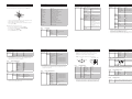
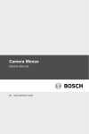
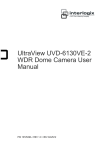
DINION 4000 - Quick Install
1a
1/2
2
3
VIDEO
Video BNC
75 Ohm
24 VAC or 12 VDC class 2 power supply
ALARM
1
2
3
4
5
6
4
+
12 VDC
24 VAC
Unlock
Back focus
5 mm
(0.2 in)
(VBN version only)
Bosch
AWG16 to 22 stranded or
AWG16 to 26 solid wire
Alarm in 1
4
Alarm in ground
not used 2
5
not used
Relay out contact 2 3
6
Relay out contact 1
VIDEO
1
2
3
ALARM
4
5
6
+
12 VDC
24 VAC
Bosch
Bos
ch
Bosch
1b
230 VAC power
Menu
1s
VIDEO
1
2
3
ALARM
Bosch
4
5
6
Bosch
Bosch
Focal length
1
1.1
Safety
1.2
Important safety instructions
1.3
FCC & ICES compliance
1.4
Focus
Bosch notices
1.
Read these instructions.
FCC & ICES Information
Disposal - Your Bosch product was developed and
Safety precautions
2.
Keep these instructions.
This equipment has been tested and found to comply with the
manufactured with high-quality material and components that
3.
Heed all warnings.
DANGER!
limits for a Class B digital device, pursuant to part 15 of the
can be recycled and reused. This symbol means that
4.
Follow all instructions
High risk: This symbol indicates an imminently hazardous
FCC Rules. These limits are designed to provide reasonable
electronic and electrical appliances, which have reached the
5.
Do not use this apparatus near water.
protection against harmful interference in a residential
situation such as "Dangerous Voltage" inside the product.
end of their working life, must be collected and disposed of
6.
Clean only with a dry cloth.
environment. This equipment generates, uses, and can radiate
If not avoided, this will result in an electrical shock, serious
separately from household waste material. Separate collecting
7.
Install in accordance with the manufacturer's instructions.
radio frequency energy and, if not installed and used in
bodily injury, or death.
systems are usually in place for disused electronic and
8.
Do not install unit near any heat sources such as radiators,
accordance with the instructions, may cause harmful
electrical products. Please dispose of these units at an
heat registers, stoves, or other apparatus (including
interference to radio communications. However, there is no
amplifiers) that produce heat.
environmentally compatible recycling facility, per European
guarantee that interference will not occur in a particular
Protect the power cord from being walked on or pinched
Directive 2002/96/EC
installation. If this equipment does cause harmful interference
If not avoided, this could result in minor or moderate bodily
particularly at plugs, convenience receptacles, and the
to radio or television reception, which can be determined by
Optical elements
injury.
point where they exit from the apparatus.
turning the equipment off and on, the user is encouraged to try
Optical elements are sensitive and should be protected at all
to correct the interference by one or more of the following
times. Do not allow objects to come into contact with glass
measures:
surfaces and do not touch optical elements with your fingers.
WARNING!
Medium risk: Indicates a potentially hazardous situation.
9.
10. Only use attachments/accessories specified by the
CAUTION!
Low risk: Indicates a potentially hazardous situation.
If not avoided, this could result in property damage or risk of
damage to the unit.
manufacturer.
11. Unplug this apparatus during lightning storms or when
unused for long periods of time.
The Low Voltage power supply unit must comply with EN60950
/ UL60065. The power supply must be a SELV-LPS unit or a
SELV - Class 2 unit (Safety Extra Low Voltage - Limited Power
Source).
reorient or relocate the receiving antenna;
–
increase the separation between the equipment and
12. Refer all servicing to service personnel. Servicing is
required when the apparatus has been damaged in any
CAUTION!
–
receiver;
–
way, such as power-supply cord or plug is damaged, liquid
has been spilled or objects have fallen into the apparatus,
the apparatus has been exposed to rain or moisture, does
connect the equipment into an outlet on a circuit different
from that to which the receiver is connected;
–
Installation should only be performed by qualified service
personnel in accordance with the National Electrical Code
NEC800 (CEC Section 60) or applicable local codes.
This manual is the intellectual property of Bosch Security
Systems and is protected by copyright.
All rights reserved.
consult the dealer or an experienced radio/TV technician
Trademarks
for help.
All hardware and software product names used in this
not operate normally, or has been dropped.
document are likely to be registered trademarks and must be
Intentional or unintentional modifications, not expressly
approved by the party responsible for compliance, shall not be
CAUTION!
Copyright
made. Any such modifications could void the user's authority to
operate the equipment. If necessary, the user should consult
the dealer or an experienced radio/television technician for
corrective action.
treated accordingly.
Note
Bosch Security Systems accepts no liability for damage
resulting directly or indirectly from faults, incompleteness or
discrepancies between the user guide and the product
described.
More information
For more information please contact the nearest Bosch Security
Systems location or visit www.boschsecurity.com
AM18-Q0643
Analog Camera Menus
1
Setup menu | en
1
Setup menu
Analog Camera Menus
1.1
Press the center button of the control pad to access the SETUP menu.
Set
Menu
Setup menu | en
Main menu
Setup menu | en
Iris setting
SHUTTER/AGC
Auto and manual exposure control
WHITE BAL
White balance setting
MODE
Backlight compensation setting
PICT ADJUST
Image adjustment setting
RETURN
BRIGHTNESS
x0.25, x0.5, x0.75, x1.0
DAY/NIGHT
Day/Night setting
RETURN
MANUAL MODE
PUSH
USER1
B-GAIN
0 - 255
R-GAIN
0 - 255
RETURN
SHUT+AGC
B-GAIN
0 - 255
1/60, 1/120, 1/250, 1/500,
R-GAIN
0 - 255
Synchronization mode setting
1/1000, /2000, 1/4000, 1/
RETURN
LANGUAGE
Language setting
10000 (NTSC)
CAMERA RESET
Restores all factory default values
SAVE ALL
Saves all settings
SHUTTER
AGC
1.1.1
1/50, 1/100, 1/250, 1/500,
ANTI CR
1/1000, 1/2000, 1/4000, 1/
MANUAL LEVEL
6, 12, 18, 24, 30, 36, 42,
PUSH
LOCK
RETURN
MANUAL
AUTO
TYPE
0 - 255
RETURN
44.8
Lens menu
LENS
USER2
10000 (PAL)
Navigation items at the bottom of the screen
To close the SETUP menu, select EXIT.
ATW
RETURN
Privacy masking setting
When the symbol
–
INDOOR, OUTDOOR
PRIVACY
–
To save changes, select SAVE ALL.
x0.5, x1.0, x1.5, x2.0
ENVIRONMENT
AGC, OFF
SYNC
–
ATW FRAME
0 - 255
MODE
Press the right or left buttons to change values.
To return to the previous menu, select BACK or RETURN.
IRIS
Video motion detection setting
–
–
0 - 255
Dynamic range setting
Digital noise reduction
To move to the continuation of a menu, select NEXT.
0 - 255
DELAY CNT
MOTION DET
Camera identification
4
White balance menu
SPEED
DYN
CAMERA ID
–
WHITE BAL
Setup menu | en
SHUT+AUTO IRIS, AUTO
LOW LUMINANCE
DNR
Analog Camera Menus
1.1.3
HIGH LUMINANCE
BRIGHTNESS
BACKLIGHT
3
Shutter/AGC (Automatic Gain Control) menu
SHUTTER/AGC AUTO
LENS
Press the up or down buttons to move the cursor through the menus.
item or open a submenu.
Analog Camera Menus
1.1.2
–
is shown, press the center button to select an
2
–
ATW (Auto Tracking White balance) and PUSH (Full pull-in: 1,800 K to
–
Use ANTI CR (Anti Color Rolling) when certain types of fluorescent light
–
Use PUSH LOCK with a reference white object filling the screen.
10,500 K) continuously analyze color temperature.
DC
MODE
OPEN, CLOSE, AUTO
SPEED
0 - 255
cause the picture to periodically change color.
RETURN
Analog Camera Menus
1.1.4
Setup menu | en
5
Backlight menu
Analog Camera Menus
1.1.7
Setup menu | en
6
Motion detection menu
Analog Camera Menus
Setup menu | en
7
Analog Camera Menus
1.1.10
Area selection for motion or privacy masks
Setup menu | en
Digital noise reduction menu
Select area 1, 2, 3 or 4 (8).
BACKLIGHT
MOTION DET
OFF
BLC
OFF
ON
0 - 127
BLOCK DISP
OFF, ON, ENABLE
Use BLC (Back Light Compensation) to see a dark object in front of a
MONITOR AREA
OFF, ON
bright background.
AREA SEL
1-4
Use HLC (High Light Compensation) to darken highlights and avoid
TOP
0 - 244 (NTSC), 288 (PAL)
image wash-out (for example, car headlights).
BOTTOM
0 - 244 (NTSC), 288 (PAL)
LEFT
0 - 474 (NTSC), 468 (PAL)
RIGHT
0 - 474 (NTSC), 468 (PAL)
HLC
–
–
–
DETECT SENSE
1.1.5
Picture adjust menu
PICT ADJUST
MIRROR
ON, OFF
BRIGHTNESS
0 - 255
CONTRAST
0 - 255
SHARPNESS
0 - 255
HUE
0 - 255
GAIN
0- 255
Top: extend or reduce upper limit of the detection area.
–
Bottom: extend or reduce bottom limit of the detection area.
–
Left: extend or reduce left limit of the detection area.
–
Right: extend or reduce right limit of the detection area.
TOP
LEFT
DYN
–
The ENABLE function sets the regions/blocks where motion detection
–
To exit the BLOCK DISP ENABLE function, press straight down on the
1
LOW, MID, HIGH
CONTRAST
LOW, MIDLOW, MID,
Camera identification menu
OFF
ON
Day/night menu
DAY/NIGHT
AUTO
Privacy masking menu
BURST
OFF, ON
control pad to move to the character you want and select it. Repeat this to
DELAY CNT
0 - 255
enter the camera ID you desire. You can enter up to 52 characters.
DAY->NIGHT
0 - 255
NIGHT->DAY
0 - 255
1.1.12
SYNC.
AREA SEL
1-8
TOP
0 - 244 (NTSC), 288 (PAL)
COLOR
0 - 244 (NTSC), 288 (PAL)
B/W
BURST
EXT
OFF, EXT1, EXT2
RIGHT
0 - 474 (NTSC), 468 (PAL)
–
When EXT is on the IR cut-off filter is switched by an external input.
Use DYN (Dynamic range setting) to improve dynamic range by highlight
COLOR
1-8
–
With EXT1 the camera switches to night mode when alarm-in is high;
compression and contrast enhancement.
TRANSP
0.00, 0.50, 0.75, 1.00
MOSAIC
OFF, ON
Only 4 areas are available if MONITOR AREA of motion detection is on.
PHASE
0 - 524 (NTSC), 624 (PAL)
OFF, ON
0 - 474 (NTSC), 468 (PAL)
RETURN
INT
RETURN
RETURN
with EXT2 the camera switches to night mode when alarm-in is low.
–
Synchronization menu
LL
OFF
LEFT
–
0 - 15
When ON is selected, a virtual keyboard appears on the screen. Use the
BOTTOM
RETURN
1.1.11
1
RETURN
PRIVACY
MIDHIGH, HIGH
–
RIGHT
C LEVEL
RETURN
1.1.9
set button for a longer time.
ON
LUMINANCE
extend
does not work.
OFF
ON
RIGHT
OFF, Y, C, Y/C
0 - 15
BOTTOM
RETURN
1.1.8
Dynamic range setting menu
reduce
DNR MODE
Y LEVEL
RETURN
CAMERA ID
RETURN
1.1.6
DNR
The output relay closes when the camera switches to NIGHT mode.
Line-Lock (LL) is only available for cameras with a VAC power supply.
Phase: 360° = 524 (NTSC), 624 (PAL).
1.1.13
LANGUAGE
Language menu
ENGLISH, JAPANESE, GERMAN, FRENCH, RUSSIAN,
PORTUGUESE, SPANISH, SIMPLIFIED CHINESE
8