1
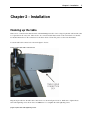
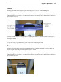
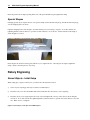
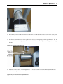
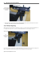
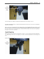
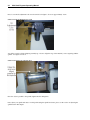
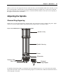
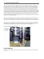
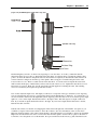
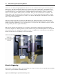
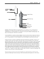
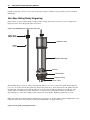
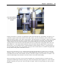
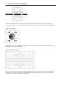
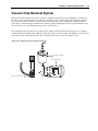
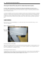
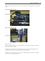
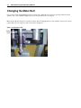
Multi Axis Engraver Operations Manual Vision Engraving & Routing Systems 17621 N. Black Canyon Hwy. Phoenix, AZ 85023 www.visionengravers.com Copyright 2005 Vision Computerized Engraving & Routing Systems (A Division of Western Engravers Supply, Inc.) All Rights Reserved This publication is protected by copyright, and all rights are reserved. No part of this manual may be reproduced or transmitted by any means or in any form, without prior written consent from Vision. Limits of Liability/Disclaimer of Warranty for this Equipment Manual The information contained within this manual has been carefully checked and is believed to be accurate, however, Vision makes no representations or warranties for this manual, and assumes no responsibility for inaccuracies, errors, or omissions that may be contained within this manual. In no event shall Vision be liable for any loss of profit including (but not limited to) direct, indirect, special, incidental, consequential, or other damages resulting from any defect or omission in this manual, even if previously advised of the possibility of such damages. In the interest of continued product development, Vision reserves the right to make improvements to this manual and the products it describes at any time, without notice or obligation. Table of Contents iii Table of Contents CHAPTER 1 - BEFORE YOU BEGIN 5 About This Manual ........................................................................................................................................5 Safety ...............................................................................................................................................................5 Unpacking and Taking Inventory.................................................................................................................6 Specifications ..................................................................................................................................................6 CHAPTER 2 - INSTALLATION 7 Hooking up the table......................................................................................................................................7 CHAPTER 3 - OPERATIONS 11 Machine Description & Terminology.........................................................................................................11 DEFINITION OF TERMS 11 Flat Engraving..............................................................................................................................................14 Flat Objects - Initial Setup .......................................................................................................................................... 14 Plates........................................................................................................................................................................... 17 Pens............................................................................................................................................................................. 17 Special Shapes ............................................................................................................................................................ 18 Rotary Engraving.........................................................................................................................................18 Round Objects - Initial Setup...................................................................................................................................... 18 Level Surface Engraving............................................................................................................................................. 20 Angled Engraving ....................................................................................................................................................... 21 Adjusting the Spindle...................................................................................................................................23 Diamond Drag Engraving ........................................................................................................................................... 23 Rotary Engraving........................................................................................................................................................ 24 Burnish Engraving ...................................................................................................................................................... 26 Non Nose Riding Rotary Engraving ........................................................................................................................... 28 CHAPTER 4 - OPTIONAL ACCESSORIES 31 Clamping Devices .........................................................................................................................................31 Vacuum Chip Removal System...................................................................................................................33 iv Multi Axis Engraver Operating Manual CHAPTER 5 - MAINTENANCE 35 Removing Chips ........................................................................................................................................... 35 Lubrication................................................................................................................................................... 36 Changing the Motor Belt ............................................................................................................................ 38 INDEX 39 Chapter 1 - Before You Begin 5 Chapter 1 - Before You Begin About This Manual This Manual is designed to provide you with information about your Multi Axis Engraver (known as MAX), beginning with unpacking the machine and continuing through installation and lifetime machine maintenance. This manual does not attempt to teach you how to engrave, how to use a computer or how to use your engraving software. Some previous knowledge of engraving terms and the engraving process is assumed. For information on the Vision Engraving Software or the Vision Pro Engraving Software, see the software manuals that came with them. For more information on your individual computer system, see your computer’s user manual or contact your computer distributor. Safety Safety Precautions for the MAX Engraver. Keep hands clear of the bottom of the spindle, the motor belt and the spindle pulley during operation. Always stop the machine before making any adjustments. Do not operate the machine with the covers removed. Wear safety glasses when cutting any materials that emit chips. Use extreme caution when inserting or removing cutters. Before any servicing, disconnect the power cord to the controller and the table cables. To avoid electric shock or equipment damage, ensure that the control unit is connected to the appropriate electrical source as noted in the installation procedures. Never operate the equipment with damaged or frayed power cords, loose connections or exposed extension cords where someone can step on the cord and create a tripping hazard. Be sure to hold the plug, not the cord, when disconnecting the controller from an electrical socket or power source. 6 Multi Axis Engraver Operating Manual Place the machine in a location with low humidity and a minimum of dust. Avoid placing the equipment in direct sunlight or in locations with excessive heat. Follow the maintenance instructions for proper cleaning of the Vision Series 3 Controller air filter, which is contained in the controller manual. If you machine does not operate properly; in particular, if there are any unusual sounds or smells coming from it, immediately unplug it and contact a service technician or your local distributor. Unplug the machine when it is going to be left unused for an extended period of time. Unpacking and Taking Inventory This area needs to be filled in when we know how the shipping boxes will be. Specifications Z-Axis Clearance: 2 inches (50.8 mm) (Definition: the distance between the bottom of the spindle and the work surface) Z-Axis Stroke: 2 inches (50.8 mm) (Definition: the travel distance of the Z-axis mechanism or spindle) Table Resolution: .0002 inch (Defintion: the smallest controlled motion the table is capable of) Engraving Area: 5“ x 9 ” (127 mm x 228 mm) Rotary Engraving Max Size: 10“ (254 mm) Overall Dimensions: Table: 31” Tall x 17“ Wide x 32” Deep (787.4 mm x 431.8 mm x 812.8mm) Controller: 16“ Tall x 16” Wide x 5“ Deep (406.4 mm x 406.8 mm x 127mm) Workholding vice: Self-centering vice with pins for holding various clamps Various cones for holding round objects Shipping Weight: 300 lbs. (136kg) Shipping Dimensions: 1 crate - 43” x 41“ x 32” (1092mm x 1041mm x 813mm) Chapter 2 - Installation 7 Chapter 2 - Installation Hooking up the table There are two connections that must be made on the MAX Engraver table. One is a large 25 pin table cable and the other is a 9 pin cable for the rotary axis. There are also two connections that must be made on the Vision Series 3 Controller. For detailed instructions on the connections for the Vision Series 3 Controller, please see the controller manual. Locate the table cable connection box shown in figure 2.1 below. (Figure 2.1) The table cable connection box Plug the 25 pin cable into the table cable connection box as shown in figure 2.2 below. Make sure to tighten the two table cable tightening screws shown below. Caution: Do not overtighten the cable tightening screws. (Figure 2.2) The table cable tightening screws 8 Multi Axis Engraver Operating Manual Locate the rotary axis cable that comes off the back of the MAX Engraver as shown in figure 2.3 below. (Figure 2.3) The rotary axis cable Connect the table cable and rotary axis cable to the back of the Vision Series 3 Controller as shown in figure 2.4 below. The serial cable shown below is the connection to your PC. For more information on this, please see the Vision Series 3 Controller manual. Note: The rotary axis and serial cables are similar in size but they are a different gender. Make sure that you plug the cables into the correct place. (Figure 2.4) The Vision Series 3 Controller connections Chapter 2 - Installation The MAX Engraver is now ready to engrave. 9 10 Multi Axis Engraver Operating Manual Chapter 3 - Operations 11 Chapter 3 - Operations Machine Description & Terminology This chapter briefly describes the major components of the MAX Engraver. The figures below show labeled drawings of the MAX Engraver. This chapter will help you identify the parts of your table discussed elsewhere in the manual. *Optional equipment such as clamps, fixtures or vacuum systems may have been included with your system. For information regarding this equipment, see the individual instructions for these options. For descriptions of controllers, computers and software used in your system, see the manuals from the manufacturers of these units. DEFINITION OF TERMS See Figure 3.1 below 1) Z Stepper Motor - This is the motor that moves the spindle up and down. 2) Spindle Pressure Adjustment Knob - This adjusts how much pressure the spindle applies on the engraved surface. Screwing the knob downward will apply more pressure and screwing the know upward will apply less pressure. 3) Z leadscrew - This is the screw that drives the up and down motion of the spindle. 4) Spindle Motor - This is the motor that turns the spindle in a clockwise direction. 5) Motor Belt - This is the drive belt that goes between the spindle motor and the spindle. 6) Spindle - This is a belt driven device that is used for rotating engraving & burninshing cutters when rotary cutting. It also mounts a diamond drag cutter for scratch engraving. 7) Spindle Micrometer and Nose Cone - The micrometer is used to adjust the depth of engraving. The nose cone rides on the surface of the material being engraved and the cutter sticks out below it. 8) Vice Pins - When using optional clamping fixtures, these pins are used to align the fixtures. 9) Vice - This is the mechanism used for clamping items to be engraved. It also allows the mounting of custom holding jigs.. 12 10) Multi Axis Engraver Operating Manual Vice Tightening Handle - Turning this handle clockwise will tighten the vice and turning this handle counterclockwise will loosen the vice. (Figure 3.1) The MAX Engraver components See Figure 3.2 below 1) Gib Adjustment Screws - These screws are used to adjust any play that may appear in the base of the vice. These are adjusted properly at the factory but can be adjusted for wear by the end user. 2) Tilt Adjustment Handle - This handle allows adjustment of the tilt of the vice. 3) Vice Slide Adjustment Screw - When loosened, this knob allows you to move the tilting vise assembly forwards or backwards to align different angles on materials. 4) Height Adjustment Knob - This screw allow you to move the tilting vise assembly up or down to accommodate different thickness materials. Chapter 3 - Operations 13 (Figure 3.2) The MAX Engraver components See Figure 3.3 below 1) Head Stock - This is where objects to be rotary engraved will be placed. This is the end that actually drives the motion. 2) Tail Stock - This is the end where the bottom of your material will be placed. This end is free wheeling and will follow the motion of the head stock. Different jigs may be used depending on the shape of the object you are engraving. (Figure 3.3) The MAX Engraver components See Figure 3.4 below 1) Optional T-Slot Table - This is an option that allows you to use a T-Slot table on the MAX Engraver. It is used to hold larger flat items that need to be engraved. 14 Multi Axis Engraver Operating Manual (Figure 3.4) The optional T-Slot table Flat Engraving Flat Objects - Initial Setup When setting up to engrave flat material, you must first adjust the distance between the bottom of the spindle nose cone and the material you are engraving. To do this, the following procedure is required: 1) Make sure that the light on the 4th Axis button on the Vision Series 3 Controller is red. If not, press the 4th axis button and the spindle will move to the center position of the machine. 2) The distance between the bottom of the spindle and the clamping device must be adjusted to approximately 1 1/2“ as shown in Figure 3.5 below. (Figure 3.5) The height adjustment distance Chapter 3 - Operations 3) 15 If the distance is greater than 1 1/2”, loosen the height adjustment screw shown below in figure 3.6. Then raise or lower the vice until the spacing is approximately 1 1/2“ and tighten the height adjustment screw. (Figure 3.6) The height adjustment knob 4) Open the vice up so that the spindle nose cone will fit inside. Then press the Z jog down button until the spindle is down inside the clamp. (see figure 3.7) 16 Multi Axis Engraver Operating Manual (Figure 3.7) Lowering the spindle into the clamp 5) Loosen the vice slide adjustment screw shown below in figure 3.8. (Figure 3.8) The vice slide adjustment screw 6) Push the clamp assembly forwards or backwards to align the spindle up in the center of the clamp. Once the clamp is centered around the spindle, tighten the vice slide adjustment screw. 7) Press the goto home button on the Vision Series 3 Controller. The spindle will move up to the z home position. 8) Press the 4th Axis button on the Vision Series 3 Controller. The spindle will now move to the back left corner of the table. 9) When you send a job to the engraver from Vision or Vision Pro, make sure that you select the MaxF Engraver or Max Flat Engraver machine driver. Using a driver other than these may result in the object not engraving properly. Chapter 3 - Operations 17 Plates Clamping plates such as name badges, desk plates and trophy plates are very easy on the MAX Engraver. Open the clamping device wide enough to accommodate the material you are trying to engrave. To do this, turn the vice tightening handle counter clockwise to open the vise and clockwise to close the vice. Insert the material into the clamp as shown in figure 3.9 below. (Figure 3.9) Clamping flat plates You must center the material you are engraving on the clamping bars. There is an adjustable material stop that you can use for quick changing of parts that are the same width. Notice that the ruler is marked from the center out to aid in centering the material. For help with setting the spindle and cutters, please see the section on adjusting the spindle. Pens Clamping pens requires the use of an optional clamp such as the pen & medallion jig. Mount the pen & medallion jig onto the clamping device using the 4 included pins & screws to secure it. Open the clamping device wide enough to accommodate the pen you are trying to engrave. To do this, turn the vice tightening handle counter clockwise to open the vise and clockwise to close the vice. Insert the material into the clamp as shown in figure 3.10 below. (Figure 3.10) Mounting a pen on the MAX engraver 18 Multi Axis Engraver Operating Manual Insert the pen into the V shaped opening in the side of the pen & medallion jig and tighten the clamp. Special Shapes Clamping special objects requires the use of an optional clamp such as the universal pin jig. Mount the universal pin jig onto the clamping device as shown. Open the clamping device wide enough to accommodate the pen you are trying to engrave. To do this, turn the vice tightening handle counter clockwise to open the vise and clockwise to close the vice. Set the material on the clamp as shown in figure 3.11 below. (Figure 3.11) Mounting a special shaped object on the MAX engraver Insert the pins into the holes in the jig that will allow you to tighten the vice. Once the pins are aligned, tighten the clamp. Always center the parts for easy setup. Rotary Engraving Round Objects - Initial Setup When setting up to engrave round objects, you must follow the instructions below: 1) Remove any flat engraving jigs that may be installed on the MAX Engraver. 2) Insert the rotary cones into the machine that will accommodate the round object you are engraving. 3) Insert the object you are engraving into the rotary cones and tighten the cones up on the object as shown in figure 3.12 below. To do this, turn the vice tightening handle counter clockwise to open the vise and clockwise to close the vice. Note: Do not overtighten. (Figure 3.12) Inserting a round object in the MAX Engraver Chapter 3 - Operations 19 4) Press the Y jog buttons on the Vision Series 3 Controller to move the spindle towards the center of the object you are engraving. 5) The distance between the bottom of the spindle and the object you are engraving should be approximately 1 1/2”. If it is not 1 1/2“, loosen the height adjustment knob and raise or lower the clamping device. See figure 3.13 for height distance. (Figure 3.13) Setting the height adjustment 6) Adjust the verticle position of the clamping device. To do this, loosen the vertical movement adjustment knob as shown below in figure 3.14. (Figure 3.14) The vertical movement adjustment knob 20 7) Multi Axis Engraver Operating Manual Move the object you are engraving forwards or backwards until the center of the object directly below the center of the spindle. Next, tighten the vertical movement adjustment knob. Level Surface Engraving When engraving round items that have a straight edge to engrave on, you need to make sure that the tilt adjustment is set for straight and not angled at all. To do this, loosen the tilt adjustment knob as shown in figure 3.15 below. (Figure 3.15) The tilt adjustment knob Next, tilt the clamping assembly up and down while tightening the tilt adjustment lock screw shown below in figure 3.16. This is a locking screw and will lock the assembly in an exact 90 degree position from the spindle. (Figure 3.16) The tilt adjustment lock screw Chapter 3 - Operations 21 Once the locking screw is tightened, re-tighten the tilt adjustment knob shown in figure 3.15 above. Next, adjust your spindle and cutter. For help with setting the spindle and cutter, please see the section on adjusting the spindle later in this chapter. When you send a job to the engraver from Vision, make sure that you select the MaxR machine driver and when you send the job from Vision Pro, make sure that you select the Max Rotary Engraver machine driver. Using a driver other than these may result in the object not engraving properly. You must enter in the diameter of the object you are engraving on the engrave screen in Vision or Vision Pro. Angled Engraving When engraving round items that have an angled surface to engrave on, you need to make sure that the tilt adjustment is set to match the angle of the object you are engraving. To do this, loosen the tilt adjustment knob as shown in figure 3.17 below. (Figure 3.17) The tilt adjustment knob 22 Multi Axis Engraver Operating Manual Next, loosen the tilt adjustment lock screw shown below in figure 3.18 screws approximately 1 turn. (Figure 3.18) The tilt adjustment lock screw You will now need to tilt the clamping assembly up or down to align the edge of the material you are engraving with the spindle. See figure 3.19 below. (Figure 3.19) Levelling the engraved object Once the object is parallel to the spindle, tighten the tilt locking knob. Next, adjust your spindle and cutter. For help with setting the spindle and cutter, please see the section on adjusting the spindle later in this chapter. Chapter 3 - Operations 23 When you send a job to the engraver from Vision, make sure that you select the MaxR machine driver and when you send the job from Vision Pro, make sure that you select the Max Rotary Engraver machine driver. Using a driver other than these may result in the object not engraving properly. You must enter in the diameter of the object you are engraving on the engrave screen in Vision or Vision Pro. Adjusting the Spindle Diamond Drag Engraving In this section, we will set up the spindle for engraving with a non-rotating cutter, such as a diamond drag cutter. Figure 3.20 below shows the spindle with the optional diamond drag adapter and how to install the adapter. (Figure 3.20) The MAX Engraver spindle with diamond drag adapter Spindle Pulley Spindle Housing Pointer Micrometer Retainer Ring Nose Cone Diamond Drag Adaptor To install the diamond drag adapter, you must first remove the retainer ring and nose. To do this, unscrew the retainer ring from the micrometer. Next, screw the diamond drag adapter onto the micrometer. Make sure that the micrometer is screwed up tight to the pointer. 24 Multi Axis Engraver Operating Manual Turn the Vision Series 3 Controller on by flipping the switch on the back right side of the machine. Set up the job you would like to engrave in the Vision or Vision Pro Software. (For more information on this, see the Vision Engraving Software manual or Vision Pro Software manual.) Insert the material you would like to engrave into the MAX Engraver as described in the next section. Use the X & Y jog keys on the Series 3 Controller to move the spindle out over the material. Now press and hold down the Z down jog button until the diamond tip touches the engraving material. Once the diamond touches the material, press the Z down jog button a little bit more. This will ensure that the depth of cut is consistent. Press the set surface button. The spindle will now move up approximately 1/8”. The distance that the spindle moved up is the distance that the spindle will move up and down between letters. If you would like a larger or smaller lift distance between characters, use the z jog up/down buttons to move the spindle to the lift position you would like. Next, press the set surface button a second time. The spindle will move up to the z home position. The surface is now set. Send the job from the computer to the Vision Series 3 Controller. You will notice that the light on the start button on the Vision Series 3 Controller will be flashing. Since we are using a diamond drag, we do not need to have the spindle rotate. On the Vision Series 3 Controller, press the spindle button until the light on the top of the button turns red. This will shut the spindle motor off. Now press start. The job should now engrave. If there are any problems, press the stop button immediately and go back through the setup. Note: You can adjust the pressure that the cutter applies to the material by adjusting the spring adjustment knob shown below in figure 3.21. Turning the knob to the left will increase the pressure causing the engraving to be slightly deeper and turning the knob to the right will decrease the pressure causing the engraving to be slightly lighter. (Figure 3.21) The spindle spring adjustment knob Rotary Engraving In this section, we will set up the spindle to engrave with a rotating cutter. Figure 3.22 below shows the spindle with a rotary cutter. Chapter 3 - Operations 25 (Figure 3.22) The MAX Engraver spindle with rotary cutter Spindle Pulley Spindle Housing Pointer Micrometer Retainer Ring Nose Cone The first thing that you need to do when rotary engraving is to zero the cutter. To do this, you must first turn the micrometer all the way up to the top. Then unscrew the micrometer 3 revolutions and stop it when the spindle pointer points to 0. Insert the cutter into the spindle and screw the cutter knob completely in. Note that the cutter will screw in counter-clockwise looking down from the top of the spindle. Take a scrap piece of material and place it flat on the bottom of the nose cone. There is a small setscrew in the cutter knob. Loosen the setscrew and push the cutter down until it touches the flat piece of material that you have at the bottom of the nose cone. Tighten the cutter knob set screw. The cutter is now zeroed. Note: Use only the special cutter wrench supplied for adjusting the cutter. The adjusting screw is not an allen key and requires the special cutter wrench. Now we must adjust the depth of cut. The depth you will need to set depends on the type of material you are engraving. You can generally find out how deep to cut engraving plastic from the manufacturer or distributor. As a general rule, you can start out shallow and increase the depth while you are engraving. Since the cutter is zeroed, we will not get any depth right now, so let’s set the depth. Turn the micrometer to the right 7 clicks. This will engrave at a depth of .007 of an inch. If you need more depth, turn the micrometer to the right. If you need less depth, turn the micrometer to the left. Each click is .001 of an inch. Turn the Vision Series 3 Controller on by flipping the switch on the back right side of the machine. Set up the job you would like to engrave in the Vision Software or Vision Pro Software. (For more information on this, see the Vision Engraving Software manual or Vision Pro Software manual.) Insert the material you would like to engrave into the MAX Engraver as described in the next section. Unscrew the cutter from the spindle. Use the X & Y jog keys on the Series 3 Controller to move the spindle out over the material. Now press and hold down the Z down jog button until the bottom 26 Multi Axis Engraver Operating Manual of the nose cone touches the engraving material. Once the nose cone touches the material, press the Z down jog button a little bit more. This will ensure that the depth of cut is consistent. Press the set surface button. The spindle will now move up approximately 1/8“. The distance that the spindle moved up is the distance that the spindle will move up and down between letters. If you would like a larger or smaller lift distance between characters, use the z jog up/down buttons to move the spindle to the lift position you would like. Next, press the set surface button a second time. The spindle will move up to the z home position. The surface is now set. Screw the cutter back into the spindle. Send the job from the computer to the Vision Series 3 Controller. You will notice that the light on the start button on the Vision Series 3 Controller will be flashing. Since we are using a rotary cutter, we need to have the spindle rotate. On the Vision Series 3 Controller, press the spindle button until the light on the button turns green. This will automatically turn the spindle motor on and off as the machine is engraving. Remember to put on your safety glasses. Now press start. The job should now engrave. If there are any problems, press the stop button immediately. Note: You can adjust the pressure that the nose cone applies to the material by adjusting the spring adjustment knob shown below in figure 3.23. Turning the knob to the left will increase the pressure and turning the knob to the right will decrease the pressure. If too much pressure is applied, you may see a slight shadow on the material you are engraving which is caused by the nose cone rubbing too hard on the material. (Figure 3.23) The spindle spring adjustment knob Burnish Engraving In this section, we will set up to engrave with a burnishing cutter. Figure 3.24 below shows the spindle with a burnishing cutter and an optional ”EZ Rider“ burnishing adapter. (Figure 3.24) The MAX Engraver spindle with burnishing cutter Chapter 3 - Operations 27 Spindle Pulley Spindle Housing Pointer Micrometer Retainer Ring Nose Cone Burnishing is different than standard rotary engraving in that you do not use the nose cone to set the depth of cut. Burnishing does not actually cut deep into metals; rather it cuts the lacquered surface off of the coated brass and aluminum material. To effectively burnish, it is recommended to use an optional ”EZ Rider“ burnishing adapter. This helps to control the pressure of the cutter on to the material. Screw the ”EZ Rider“ into spindle. Note that the ”EZ Rider“ will screw in counter-clockwise looking down from the top of the spindle. Next, insert the cutter through the ”EZ Rider“ and through the spindle so that the cutter sticks out below the nose cone approximately 1/8 of an inch. Tighten the setscrew in the ”EZ Rider“ with the special cutter wrench. Turn the Vision Series 3 Controller on by flipping the switch on the back right side of the machine. Set up the job you would like to engrave in the Vision Software or Vision Pro Software. (For more information on this, see the Vision Engraving Software manual or Vision Pro Software manual.) Insert the material you would like to engrave into the MAX Engraver as described in the next section. Use the X & Y jog keys on the Series 3 Controller to move the spindle out over the material. Now press and hold down the Z down jog button until the bottom of the cutter touches the engraving material. Once the cutter touches the material, press the Z down jog button a little bit more. This will ensure that the depth of cut is consistent. Press the set surface button. The spindle will now move up approximately 1/8”. The distance that the spindle moved up is the distance that the spindle will move up and down between letters. If you would like a larger or smaller lift distance between characters, use the z jog up/down buttons to move the spindle to the lift position you would like. Next, press the set surface button a second time. The spindle will move up to the z home position. The surface is now set. Send the job from the computer to the Vision Series 3 Controller. You will notice that the light on the start button on the Vision Series 3 Controller will be flashing. Since we are using a rotary cutter, we need to have the spindle rotate. On the Vision Series 3 Controller, press the spindle button until the light on the button turns green. This will automatically turn the spindle motor on and off as the 28 Multi Axis Engraver Operating Manual machine is engraving. Now press start. The job should now engrave. If there are any problems, press the stop button immediately. Non Nose Riding Rotary Engraving In this section, we will set up the spindle to engrave with a rotating cutter and not use the nose cone for depth control. Figure 3.25 below shows the spindle with a rotary cutter. (Figure 3.25) The MAX Engraver spindle with rotary cutter Spindle Pulley Spindle Housing Pointer Micrometer Retainer Ring Nose Cone The first thing that you need to do when rotary engraving with no nose cone is to remove the spindle retainer ring and nose cone. To do this, unscrew the retainer ring shown in the picture above. Insert the cutter into the spindle and screw the cutter knob completely in. Note that the cutter will screw in counter-clockwise looking down from the top of the spindle. There is a small setscrew in the cutter knob. Loosen the setscrew and push the cutter down until there is approximately 1/4“ of the cutter sticking out below the bottom of the spindle. Tighten the cutter knob set screw. Note: You will need to lock the spindle so that there is no spring float. To do this, turn the spring adjustment knob to the left until it reaches the bottom of its travel. This will lock the spindle. See figure 3.26 below. (Figure 3.26) The spindle spring adjustment knob Chapter 3 - Operations 29 Turn the Vision Series 3 Controller on by flipping the switch on the back right side of the machine. Set up the job you would like to engrave in the Vision Software or Vision Pro Software. (For more information on this, see the Vision Engraving Software manual or Vision Pro Software manual.) Insert the material you would like to engrave into the MAX Engraver as described in the next section. Use the X & Y jog keys on the Series 3 Controller to move the spindle out over the material. Now press and hold down the Z down jog button until the bottom of the cutter just touches the engraving material. Once the cutter touches the material, press the set surface button. The spindle will now move up approximately 1/8”. The distance that the spindle moved up is the distance that the spindle will move up and down between letters. If you would like a larger or smaller lift distance between characters, use the z jog up/down buttons to move the spindle to the lift position you would like. Next, press the set surface button a second time. The spindle will move up to the z home position. The surface is now set. Since we are not using the nose cone to adjust the engraving depth, the depth must be set in the Vision or Vision Pro engraving software. To do this, please see the section on Pass Depths in the Vision manual or the section on Creating Tool Paths in the Vision Pro software manual. Send the job from the computer to the Vision Series 3 Controller. You will notice that the light on the start button on the Vision Series 3 Controller will be flashing. Since we are using a rotary cutter, we need to have the spindle rotate. On the Vision Series 3 Controller, press the spindle button until the light on the button turns green. This will automatically turn the spindle motor on and off as the machine is engraving. Now press start. The job should now engrave. If there are any problems, press the stop button immediately. 30 Multi Axis Engraver Operating Manual Chapter 4 - Optional Accessories Chapter 4 - Optional Accessories Clamping Devices Below are some optional clamping devices that may be necessary for holding certain types of objects. (Figure 4.1) The Universal Clamping Bars These clamping bars are specially designed to hold both 1/16“ and 1/8” thick materials and allow engraving up to the edge of the material without nosecone interference. Other uses include holding metal engraving stock, name badges or other rectangular shapes. The part number for this holder is 200109-00. (Figure 4.2) The Universal Seal & Medallion holder This universal clamp will hold 1-3 round objects at a time. It also has a place for the “eye” of a medallion or tag. This clamp may be used to any diameter of notary seal. The part number for this holder is 200110-00. (Figure 4.3) The Pen & Medallion jig 31 32 Multi Axis Engraver Operating Manual These jaws enable engraving on all types of pens and other small cylindrical objects. Rotating the jaws 180º allows engraving on medallions, notary seals, pet tags and other round objects. The part number for this holder is 200106-00. (Figure 4.4) The Seal jig Designed for notary seals of all diameters. Rotating the jaw 180º will allow clamping of both large and small sizes. The part number for this holder is 200107-00. (Figure 4.5) The Universal Pin Jig This is a true universal clamp designed for holding odd shaped items such as state badges, hearts, and medallions with unusual borders, pet tags, jewelry and more. The dowel pins may be moved anywhere on the jaw to accommodate any odd shape. The part number for this holder is 200111-00. Chapter 4 - Optional Accessories 33 Vacuum Chip Removal System The optional vacuum chip removal system is designed to simplify the engraving process and minimize wear and tear on the engraver. The vacuum chip removal system uses a vacuum nose cone to remove chips created during the engraving process before they have the chance to create problems. The quiet pump, coupled with the micro fine-layered filters assures that your unwanted chips are whisked away effortlessly. The vacuum pump canister uses replaceable filters that can also be reused, to assure maximum efficiency and cost-effectiveness. The vacuum chip removal system allows prompt removal of chips and dust created in the engraving process, reducing contamination and overheating in the spindle area. Chip removal also prevents the cutter from skipping over letters due to stray particles. This vacuum chip removal system is available with or without a Vision vacuum nose cone. (Figure 4.6) The Optional Vacuum Chip Removal System 34 Multi Axis Engraver Operating Manual Chapter 5 - Maintenance 35 Chapter 5 - Maintenance Removing Chips Vision strives for the highest quality in their manufacturing process to provide you with the most cost effective, reliable engraving machine in use today. Please remember that proper maintenance and care is necessary to achieve maximum product life expectancy. The engraving environment generates small plastic and metal chips as well as other particles during operation. As with any machinery, your engraving system should be kept as clean as possible to minimize wear and tear, and to improve final quality of the engraved product. Removing Chips Plastic and metal chips, generated during the engraving process, should be removed from the engraving surface periodically. A portable vacuum is suggested for chip removal, but applying direct suction to the spindle area is not recommended. Note that this cleaning can be minimized and greatly simplified through the use of the optional vacuum chip removal system. The vacuum chip removal system removes chips and dust created by engraving. This system can also extend the life of other components in the system, as prompt removal of chips reduces contamination and overheating in the spindle area. The vacuum chip removal system also keeps the nose cone from skipping over letters due to chips on the engraving surface. Cleaning The Nose Cone The nose cone around the cutter may accumulate dust and chips that cannot be removed by sucking them off or blowing on them with low-pressure air. Always wear safety glasses when using high pressure air. CAUTION! High-pressure air can damage the spindle.) Two types of nose cones are available; one nose cone is designed to be used with the vacuum system, the other is not. Cleaning methods depend on the type of nose cone in use. With a vacuum chip removal system, most of the chips will be removed during the engraving process. If the suction nozzle becomes clogged, remove the hose connection to the nose cone. Remove the cutter, then unscrew the vacuum nose cone. Using a vacuum or an air hose, clean out the nose and the vacuum tube leading to the nose cone. Reinstall the nose cone and the vacuum hose. Without a vacuum chip removal system you should remove the cutter before attempting to clean the nose cone. The nose cone retainer ring, the nose cone, and the micrometer collar should all be removed and cleaned using a vacuum or low pressure blowing air. The three nose cone components should be removed and cleaned at least every day, and as frequently as necessary. Failure to clean the nose cone regularly will result in premature spindle failure. 36 Multi Axis Engraver Operating Manual Cleaning the Vacuum Filter (only with the vacuum chip removal option) On systems with a vacuum chip removal system, frequent cleaning of the vacuum filter is necessary for proper performance. When engraving with the vacuum filter system, the filter should be checked and cleaned several times a day, depending on the amount of engraving done. If the vacuum does not appear to be functioning efficiently, clean the filter more frequently as needed. To clean the vacuum filter system, disconnect the vacuum hose from the canister. On the lid of the canister, note the three snap clips. Loosen these clips to allow the removal of the lid. Remove the canister lid and inside you will find the filter. Carefully remove the filter. Empty the filter and shake it out completely, being careful not to damage it, as the filters are reusable. Place the filter back inside the canister, put the lid back on the canister and then snap the three clips back into place. Lubrication Remove the top cover from the MAX Engraver. To do this, remove the 2 screws from each side of the top cover as shown below in figure 5.1 (Figure 5.1) The Top Cover Screws Lubricating the X&Y-Axis Linear Rails: Apply 2-3 drops of light oil (such as 3-in-1 oil) on the rails and rub it in with your fingers. Use the X jog button to move the spindle to the right and left to evenly distribute the oil. Also, use the Y jog button to move the spindle from front to back to evenly distribute the oil. See Figure 5.2 below. Lubricating the X-Y-Z-Axis lead screws: A light lubrication of the X, Y and Z lead screws should be performed after 2-4 weeks of usage. Use silicone lubricant or an equivalent that has no teflon additives. Since the leadscrews have a teflon coating, using a lubricant with a teflon additive may wear the teflon off of the leadscrews.See Figures 5.2 & 5.3 below. Chapter 5 - Maintenance DO NOT use any lubricant other than silicone, as it may become sticky and cause a buildup that can cause mechanical failure. (Figure 5.2) The Lubrication Areas (Figure 5.3) The Lubrication Areas What not to lubricate Many of the bearings and assemblies in your engraving machine are sealed and/or coated using special low-friction methods and should not be lubricated. DO NOT attempt to lubricate the spindle or the spindle bearings. If you suspect lubrication problems, call your dealer/representative for instructions, as further lubrication may harm the machine. DO NOT oil the X or Y stepper motors. None of the motors on the MAX Engraver require lubrication. Oiling the stepper motors can permanently damage the motors. 37 38 Multi Axis Engraver Operating Manual Changing the Motor Belt Over a period of time, the MAX Engraver motor belt will wear. When the motor belt wears it will stretch and cause the spindle to slip or stall. When this happens, the motor belt generally needs to be changed. Make sure that the Vision Series 3 Controller is turned off before changing the motor belt. Pull the old motor belt off and replace with a new one. The motor belt is shown below in figure 5.4. (Figure 5.4) The Motor Belt Index Index —A— About This Manual, 5 Angled Engraving, 21 —B— Burnish Engraving, 26 —C— Changing the Motor Belt, 38 Clamping Devices, 31 —E— Engraving - Burnishing, 26 Engraving - Non Rotating, 23 Engraving - Rotary, 24, 28 —H— Hooking up the table, 7 —I— Initial Setup, 14, 18 —L— Lubrication, 36 —M— Machine Description & Terminology, 11 Maintenance, 35 —N— Non Nose Rotary Engraving, 28 —P— Pens, 17 Plates, 17 —R— Removing Chips, 35 Rotary Engraving, 24 —S— Safety, 5 Special Shapes, 18 Specifications, 6 Straight Engraving, 20 —U— Unpacking and Taking Inventory, 6 —V— Vacuum Chip Removal System, 33 39 40 Multi Axis Engraver Operating Manual Index 41