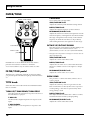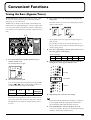
1
Owner’s Manual
Thank you, and congratulations on your choice of the BOSS ME-50B Bass Multiple Effects.
Before using this unit, carefully read the sections entitled: “USING THE UNIT SAFELY” (page 2–3) and
“IMPORTANT NOTES” (page 4).
These sections provide important information concerning the proper operation of the unit. Additionally, in order to
feel assured that you have gained a good grasp of every feature provided by your new unit, owner’s manual should
be read in its entirety. The manual should be saved and kept on hand as a convenient reference.
Main features
Simple Operation—Works Like a
Compact Effects Processor
Multi-Function Expression Pedal
Each effect is controlled with a dedicated knob.
Intuitive operation, similar to that of compact effects
processors, lets you make changes to tones directly.
The ME-50B is equipped with an expression pedal that
gives you control over six different specialized pedal
effects. It can also be switched for use as a volume
pedal.
High-Quality Sounds Through COSM
Memory Function
With high-quality effects like Compressor/Limiter and
Overdrive/Distortion, which make full use of COSM
technology, you can perform with a variety of powerful
effects, from classic vintage sounds to new and original
sounds.
You can store up to 24 original tones you have created.
You can also use the pedals in “Memory mode” to call
up stored tones instantly.
COSM (Composite Object Sound Modeling)
Composite Object Sound Modeling (COSM) is Roland’s
innovative and powerful sound modeling technology.
COSM analyzes the many factors that make up the
original sound, such as the electrical and physical
characteristics of the original, and then produces a
digital model that can reproduce the same sound.
Copyright © 2003 BOSS CORPORATION
All rights reserved. No part of this publication
may be reproduced in any form without the
written permission of BOSS CORPORATION.
AUX IN Jack
The AUX IN jack makes it easy to practice along with
CDs, MDs, and other input.
Battery-Powered Operation
The ME-50B can be powered in two ways, with (6) AA
batteries or by using the AC adaptor (optional).
USING THE UNIT SAFELY
The
symbol alerts the user to important instructions
or warnings.The specific meaning of the symbol is
determined by the design contained within the
triangle. In the case of the symbol at left, it is used for
general cautions, warnings, or alerts to danger.
Used for instructions intended to alert
the user to the risk of death or severe
injury should the unit be used
improperly.
Used for instructions intended to alert
the user to the risk of injury or material
damage should the unit be used
improperly.
* Material damage refers
other adverse effects
respect to the home
furnishings, as well
animals or pets.
The
symbol alerts the user to items that must never
be carried out (are forbidden). The specific thing that
must not be done is indicated by the design contained
within the circle. In the case of the symbol at left, it
means that the unit must never be disassembled.
to damage or
caused with
and all its
to domestic
The ● symbol alerts the user to things that must be
carried out. The specific thing that must be done is
indicated by the design contained within the circle. In
the case of the symbol at left, it means that the powercord plug must be unplugged from the outlet.
001
009
• Before using this unit, make sure to read the
instructions below, and the Owner’s Manual.
• Do not excessively twist or bend the power cord,
nor place heavy objects on it. Doing so can
damage the cord, producing severed elements and
short circuits. Damaged cords are fire and shock
hazards!
..........................................................................................................
..........................................................................................................
002c
• Do not open (or modify in any way) the unit or its
AC adaptor.
..........................................................................................................
003
• Do not attempt to repair the unit, or replace parts
within it (except when this manual provides
specific instructions directing you to do so). Refer
all servicing to your retailer, the nearest Roland
Service Center, or an authorized Roland
distributor, as listed on the “Information” sheet.
..........................................................................................................
004
• Never use or store the unit in places that are:
• Subject to temperature extremes (e.g., direct
sunlight in an enclosed vehicle, near a heating
duct, on top of heat-generating equipment); or
are
• Damp (e.g., baths, washrooms, on wet floors);
or are
• Humid; or are
• Exposed to rain; or are
• Dusty; or are
• Subject to high levels of vibration.
..........................................................................................................
007
• Make sure you always have the unit placed so it is
level and sure to remain stable. Never place it on
stands that could wobble, or on inclined surfaces.
..........................................................................................................
008b
• Use only the specified AC adaptor (PSA series),
and make sure the line voltage at the installation
matches the input voltage specified on the AC
adaptor’s body. Other AC adaptors may use a
different polarity, or be designed for a different
voltage, so their use could result in damage,
malfunction, or electric shock.
..........................................................................................................
2
010
• This unit, either alone or in combination with an
amplifier and headphones or speakers, may be
capable of producing sound levels that could
cause permanent hearing loss. Do not operate for
a long period of time at a high volume level, or at
a level that is uncomfortable. If you experience
any hearing loss or ringing in the ears, you should
immediately stop using the unit, and consult an
audiologist.
..........................................................................................................
011
• Do not allow any objects (e.g., flammable material,
coins, pins); or liquids of any kind (water, soft
drinks, etc.) to penetrate the unit.
..........................................................................................................
012c
• Immediately turn the power off, remove the AC
adaptor from the outlet, and request servicing by
your retailer, the nearest Roland Service Center, or
an authorized Roland distributor, as listed on the
“Information” sheet when:
• The AC adaptor or the power-supply cord has
been damaged; or
• If smoke or unusual odor occurs
• Objects have fallen into, or liquid has been
spilled onto the unit; or
• The unit has been exposed to rain (or otherwise
has become wet); or
• The unit does not appear to operate normally or
exhibits a marked change in performance.
..........................................................................................................
013
107d
• In households with small children, an adult
should provide supervision until the child is
capable of following all the rules essential for the
safe operation of the unit.
..........................................................................................................
• Never handle the AC adaptor body, or its output
plugs, with wet hands when plugging into, or
unplugging from, an outlet or this unit.
..........................................................................................................
014
• Protect the unit from strong impact.
(Do not drop it!)
..........................................................................................................
015
• Do not force the unit’s power-supply cord to share
an outlet with an unreasonable number of other
devices. Be especially careful when using
extension cords—the total power used by all
devices you have connected to the extension
cord’s outlet must never exceed the power rating
(watts/amperes) for the extension cord. Excessive
loads can cause the insulation on the cord to heat
up and eventually melt through.
..........................................................................................................
016
• Before using the unit in a foreign country, consult
with your retailer, the nearest Roland Service
Center, or an authorized Roland distributor, as
listed on the “Information” sheet.
..........................................................................................................
019
• Batteries must never be recharged, heated, taken
apart, or thrown into fire or water.
108b
• Before moving the unit, disconnect the AC
adaptor and all cords coming from external
devices.
..........................................................................................................
109b
• Before cleaning the unit, turn off the power and
unplug the AC adaptor from the outlet.
..........................................................................................................
110b
• Whenever you suspect the possibility of lightning
in your area, disconnect the AC adaptor from the
outlet.
..........................................................................................................
111: Selection
• If used improperly, batteries may explode or leak
and cause damage or injury. In the interest of
safety, please read and observe the following
precautions (p. 6).
1
• Carefully follow the installation instructions for
batteries, and make sure you observe the correct
polarity.
2
• Avoid using new batteries together with used
ones. In addition, avoid mixing different types
of batteries.
3
• Remove the batteries whenever the unit is to
remain unused for an extended period of time.
..........................................................................................................
5
• If a battery has leaked, use a soft piece of cloth
or paper towel to wipe all remnants of the
discharge from the battery compartment. Then
install new batteries. To avoid inflammation of
the skin, make sure that none of the battery
discharge gets onto your hands or skin. Exercise
the utmost caution so that none of the discharge
gets near your eyes. Immediately rinse the
affected area with running water if any of the
discharge has entered the eyes.
101b
• The unit and the AC adaptor should be located so
their location or position does not interfere with
their proper ventilation.
..........................................................................................................
102d
• Always grasp only the output plug or the body of
the AC adaptor when plugging into, or
unplugging from, this unit or an outlet.
..........................................................................................................
103b
• At regular intervals, you should unplug the AC
adaptor and clean it by using a dry cloth to wipe
all dust and other accumulations away from its
prongs. Also, disconnect the power plug from the
power outlet whenever the unit is to remain
unused for an extended period of time. Any
accumulation of dust between the power plug and
the power outlet can result in poor insulation and
lead to fire.
..........................................................................................................
6
• Never keep batteries together with metallic
objects such as ballpoint pens, necklaces,
hairpins, etc.
..........................................................................................................
112
• Used batteries must be disposed of in compliance
with whatever regulations for their safe disposal
that may be observed in the region in which you
live.
..........................................................................................................
104
• Try to prevent cords and cables from becoming
entangled. Also, all cords and cables should be
placed so they are out of the reach of children.
..........................................................................................................
106
• Never climb on top of, nor place heavy objects on
the unit.
..........................................................................................................
3
IMPORTANT NOTES
In addition to the items listed under “USING THE UNIT SAFELY” on page 2–3, please read and observe the following:
Power Supply: Use of Batteries
Maintenance
301
401a
• Do not connect this unit to same electrical outlet that is
being used by an electrical appliance that is controlled by
an inverter (such as a refrigerator, washing machine,
microwave oven, or air conditioner), or that contains a
motor. Depending on the way in which the electrical
appliance is used, power supply noise may cause this unit
to malfunction or may produce audible noise. If it is not
practical to use a separate electrical outlet, connect a
power supply noise filter between this unit and the
electrical outlet.
• For everyday cleaning wipe the unit with a soft, dry cloth
or one that has been slightly dampened with water. To
remove stubborn dirt, use a cloth impregnated with a
mild, non-abrasive detergent. Afterwards, be sure to wipe
the unit thoroughly with a soft, dry cloth.
302
• The AC adaptor will begin to generate heat after long
hours of consecutive use. This is normal, and is not a
cause for concern.
303a
• The use of an AC adaptor is recommended as the unit’s
power consumption is relatively high. Should you prefer
to use batteries, please use the alkaline type.
304a
• When installing or replacing batteries, always turn off the
power on this unit and disconnect any other devices you
may have connected. This way, you can prevent
malfunction and/or damage to speakers or other devices.
306b
• Batteries are supplied with the unit. The life of these
batteries may be limited, however, since their primary
purpose was to enable testing.
307
• Before connecting this unit to other devices, turn off the
power to all units. This will help prevent malfunctions
and/or damage to speakers or other devices.
Placement
351
• Using the unit near power amplifiers (or other equipment
containing large power transformers) may induce hum.
To alleviate the problem, change the orientation of this
unit; or move it farther away from the source of interference.
352a
• This device may interfere with radio and television
reception. Do not use this device in the vicinity of such
receivers.
352b
• Noise may be produced if wireless communications
devices, such as cell phones, are operated in the vicinity of
this unit. Such noise could occur when receiving or initiating a call, or while conversing. Should you experience
such problems, you should relocate such wireless devices
so they are at a greater distance from this unit, or switch
them off.
354a
• Do not expose the unit to direct sunlight, place it near
devices that radiate heat, leave it inside an enclosed
vehicle, or otherwise subject it to temperature extremes.
Excessive heat can deform or discolor the unit.
355b
• When moved from one location to another where the
temperature and/or humidity is very different, water
droplets (condensation) may form inside the unit. Damage
or malfunction may result if you attempt to use the unit in
this condition. Therefore, before using the unit, you must
allow it to stand for several hours, until the condensation
has completely evaporated.
402
• Never use benzine, thinners, alcohol or solvents of any
kind, to avoid the possibility of discoloration and/or
deformation.
Repairs and Data
452
• Please be aware that all data contained in the unit’s
memory may be lost when the unit is sent for repairs.
Important data should always be written down on paper
(when possible). During repairs, due care is taken to avoid
the loss of data. However, in certain cases (such as when
circuitry related to memory itself is out of order), we
regret that it may not be possible to restore the data, and
Roland assumes no liability concerning such loss of data.
Additional Precautions
551
• Please be aware that the contents of memory can be
irretrievably lost as a result of a malfunction, or the
improper operation of the unit. To protect yourself against
the risk of loosing important data, we recommend that
important data should always be written down on paper.
552
• Unfortunately, it may be impossible to restore the contents
of data that was stored in the unit’s memory once it has
been lost. BOSS/Roland Corporation assumes no liability
concerning such loss of data.
553
• Use a reasonable amount of care when using the unit’s
buttons, sliders, or other controls; and when using its jacks
and connectors. Rough handling can lead to malfunctions.
554
• Never strike or apply strong pressure to the display.
556
• When connecting / disconnecting all cables, grasp the
connector itself—never pull on the cable. This way you
will avoid causing shorts, or damage to the cable’s
internal elements.
558a
• To avoid disturbing your neighbors, try to keep the unit’s
volume at reasonable levels. You may prefer to use
headphones, so you do not need to be concerned about
those around you (especially when it is late at night).
559a
• When you need to transport the unit, package it in the box
(including padding) that it came in, if possible. Otherwise,
you will need to use equivalent packaging materials.
562
• Use a cable from Roland to make the connection. If using
some other make of connection cable, please note the
following precautions.
• Some connection cables contain resistors. Do not use
cables that incorporate resistors for connecting to this
unit. The use of such cables can cause the sound level
to be extremely low, or impossible to hear. For information on cable specifications, contact the manufacturer of the cable.
988
• Security Slot ( )
http://www.kensington.com/
220
• All product names mentioned in this document are trademarks or registered trademarks of their respective owners.
4
Contents
USING THE UNIT SAFELY ................... 2
Saving and Loading the Created Tones
(Memory Mode) ............................. 21
IMPORTANT NOTES .......................... 4
Switching Between Manual and Memory Mode ........... 21
Playing Sounds ................................ 6
About the Patch....................................................... 21
Installing Batteries .................................................... 6
Write Procedure ...................................................... 22
Making the Connections........................................... 6
Calling Up and Using Stored Tones (Patch Change) ... 22
Turning on the Power ............................................... 7
Adjusting the Volume................................................. 7
Turning Off the Power .............................................. 7
Using the Effects ............................... 8
About the Effect Connection Sequence.................. 8
COMPRESSOR/LIMITER........................................... 9
Switching Numbers................................................... 22
Switching Banks......................................................... 22
Notes When Using Memory Mode ......................... 23
About Tone Changes................................................. 23
About the Tempo Setting.......................................... 23
About the HOLD DLY .............................................. 23
About the .TAP DLY ............................................... 23
Changing the Patch Settings (Patch Edit mode) .......... 24
FILTER/TONE........................................................... 10
DRIVE/SYNTH .......................................................... 12
Convenient Functions...................... 25
DELAY/MODULATION............................................. 14
Using the HOLD DLY Function .............................. 16
Using the .TAP DLY Function............................... 16
Adding a Delay
Synchronized to the Performance Tempo.............. 16
Adding a Modulation Effect
Synchronized to the Performance Tempo.............. 17
Tuning the Bass (Bypass/Tuner) ........................... 25
Pedal......................................................................... 18
Using the Pedal as a Volume Pedal ........................ 18
Using the Pedal as an Expression Pedal................. 18
Using the SOUND HOLD Function ....................... 19
Using the KICK DRUM Function............................ 19
Using the Foot Switch ............................................ 26
Switching the Compressor/Limiter On and Off ........... 26
Adding an Effect
Synchronized to the Performance Tempo.............. 26
Switching Banks......................................................... 27
Practicing Along with CDs and MDs (AUX IN)...... 27
Appendices .................................... 28
Returning the ME-50B
to Its Factory Settings (Factory Reset) ................. 28
Adjusting the Expression Pedal ............................ 28
MASTER ................................................................... 20
Troubleshooting ...................................................... 29
NOISE SUPPRESSOR ............................................. 20
Specifications .......................................................... 30
A Note About Bypass ............................................. 20
Patch List........................................ 31
Factory Settings.............................. 32
Blank Chart.................................... 34
Index ............................................. 38
Conversions Used in This Manual
●
Words in square brackets [ ] indicate panel buttons or knobs.
(Example)
[WRITE]:
●
WRITE button
(p. **) indicates a reference page.
5
Playing Sounds
Installing Batteries
* Batteries are supplied with the unit. The life of these batteries
may be limited, however, since their primary purpose was to
enable testing.
Insert the included batteries as shown in figure, being careful
to orient the batteries correctly.
fig.0010
Making the Connections
The ME-50B is not equipped with any internal amplifier or
speakers. To listen to sound with the ME-50B, connect it to a
bass amp, stereo headphones, or other such sound
equipment.
* To prevent malfunction and/or damage to speakers or other
devices, always turn down the volume, and turn off the power
on all devices before making any connections.
fig.0020
Bass Guitar
Stereo
Headphones
AC Adaptor
(PSA series: optional)
CD/MD
Player, etc.
• When turning the unit upside-down, get a bunch of
newspapers or magazines, and place them under the
four corners or at both ends to prevent damage to the
buttons and controls. Also, you should try to orient the
unit so no buttons or controls get damaged.
Bass Amp
●
If there are batteries in the unit while an AC adaptor is
being used, normal operation will continue should the
line voltage be interrupted (power blackout or power
cord disconnection from the ME-50B).
●
To prevent the inadvertent disruption of power to your
unit (should the plug be pulled out accidentally), and to
avoid applying undue stress to the AC adaptor jack,
anchor the power cord using the cord hook, as shown in
the illustration.
• When turning the unit upside-down, handle with care to
avoid dropping it, or allowing it to fall or tip over.
• Make sure the “+” and “-” ends of the batteries are
oriented correctly.
• A “b” appears in the display when the batteries are
nearly worn out. When this occurs, replace with new
batteries.
• When replacing the batteries, use six AA type.
fig.0040
• Avoid using new batteries together with used ones. In
addition, avoid mixing different types of batteries. Doing
so can result in fluid leakage.
• Battery life can vary depending on battery type.
Continuous usage time under battery power is about 12
hours with alkaline batteries and about 3.5 hours with
carbon batteries.
(This may vary according to usage conditions.)
6
●
When outputting monaurally, connect a cable only to the
OUTPUT L (MONO) jack.
●
Do not use a cable containing a resistor to connect CD or
MD players to the AUX IN jack. If a cable incorporating
resistance is used, audio from CD and MD players may
become inaudible.
Playing Sounds
Turning on the Power
Once the connections have been completed, turn on power to
your various devices in the order specified. By turning on
devices in the wrong order, you risk causing malfunction
and/or damage to speakers and other devices.
* If using the ME-50B with a CD or MD player, be sure to turn
on the power to the connected device first.
If There Is No Sound/If the Volume is Low
●
Check the connections once more.
●
●
1. ME-50B
●
Is the ME-50B in Tuner mode (p. 25)?
In Tuner mode, the bypass sound is output, and the
expression pedal is used as a volume pedal.
* This unit is equipped with a protection circuit. A brief interval
(several seconds) after power up is required before the unit will
operate normally.
fig.0050
Has the level been lowered with the expression pedal?
Sounds are not output when the toe of the expression
pedal is in the raised position while the pedal is set to
function as a volume pedal (p. 18).
2. Bass Amp /Stereo, Multitrack Recorder, Etc.
Adjust the ME-50B’s volume with the MASTER LEVEL knob.
Can you hear sound through the headphones when
headphones are connected?
If you can hear sounds, it may be that there is a short in
the cable used to connect the amp or other device, or
perhaps a mistake in an external device’s settings. Check
the connecting cables and external devices once more.
●
Adjusting the Volume
Is the volume turned down?
Check the volume levels on any connected amp or mixer.
fig.0041
* Turn up the volume on amps and other equipment only after
all connections are completed and the power for connected
devices is turned on.
Are connections to other devices correctly made?
When the expression pedal is used as a volume pedal,
sound output falls as you pull the pedal back, raising the
front of the pedal (p. 18).
●
Is a cable containing a resistor being used to connect a
CD or MD player to the AUX IN jack?
Using a cable containing a resistor may prevent sound
from CD and MD players from being audible.
Turning Off the Power
* Raising the MASTER LEVEL knob too much may result in
sound distortion.
* When the effects are all off, input and output are at the same
levels as when the MASTER LEVEL knob is at the center
position.
1. Turn down the volume of the ME-50B and any
connected device.
2. Turn off the power to Bass Amp / Stereo, Multitrack
Recorder, etc.
3. Turn the ME-50B’s power off.
* The setting of the MASTER LEVEL knob is stored in memory
for each patch (p. 21).
7
Using the Effects
When the power is turned on, the FILTER/TONE, DRIVE/SYNTH, and DELAY/MODULATION are switched off. Also, the
expression pedal will function as volume pedal.
* When the DELAY/MODULATION TYPE is set to HOLD DLY, the DELAY/MODULATION indicator goes on, the DELAY/MOD
pedal's indicator flashes at a fixed interval, indicating recording standby is enabled. (p. 16)
All product names mentioned in this document are trademarks or registered trademarks of their respective owners.
Those companies are not affiliated with BOSS and have not licensed or authorized BOSS’s ME-50B. Their marks are used
solely to identify the equipment whose sound is simulated by BOSS’s ME-50B.
About the Effect Connection Sequence
The ME-50B automatically selects the optimum sequence for connecting the effects according to the effect settings.
fig.0060
DRIVE/SYNTH = SYNTH
+1 OCTAVE / DRIVE/SYNTH = Others
-1 OCTAVE
(EXPRESSION)
SAW LEAD /
MILD FILTER /
DEEP FILTER /
SQUARE
(DRIVE / SYNTH)
OCTAVE UP /
SLOW GEAR /
DEFRETTER /
ENHANCER /
BOTTOM BOOST /
MID SHAPE /
HOLLOW
(FILTER / TONE)
EQ
(MASTER)
NOISE
SUPPRESSOR
COMPRESSOR /
LIMITER
OCTAVE
DOWN
(FILTER / TONE)
FOOT
VOLUME
NATURAL /
BASS DRIVER /
OVER DRIVE /
DISTORTION /
MUFF FUZZ /
METAL /
HI-BAND DRIVE
(DRIVE / SYNTH)
SOUND
HOLD
T.WAH UP /
T.WAH DOWN /
T.WAH EDGE
WAH /
RESONANCE
(FILTER / TONE)
(EXPRESSION)
DELAY /
MODULATION
(MASTER)
(EXPRESSION)
DELAY/MOD = HOLD DLY
KICK DRUM
(EXPRESSION)
8
LEVEL
DELAY/MOD = Others
Using the Effects
COMPRESSOR/LIMITER
fig.0110
COMPRESSOR/LIMITER indicator
THRESHOLD/SUSTAIN knob
Adjusts the depth of the effect.
When the TYPE is set to NATURAL, LIMITER, 160D SOFT,
or 160D HARD, this functions as the THRESHOLD knob,
which sets the level at which the limiter starts to take effect.
The more the knob is turned to the left (counterclockwise),
the lower the level at which the limiter effect is enabled.
This comprises two effects, one that evens out the volume of
the input signals to provide lengthy sustain (compressor),
and one that prevents distortion by suppressing only the
peaks in the sound (limiter).
When the TYPE is set to D-COMP, the knob functions as a
SUSTAIN control, which adjusts how long sounds are
sustained. Turn the knob to the right (clockwise) to get
longer sustain times.
TYPE knob
LEVEL knob
OFF
Turns off the compressor/limiter effect sound is
bypassed.
* The COMPRESSOR/LIMITER indicator goes off when this is
set to OFF.
NATURAL
This adjusts the level when the compressor/limiter is on. Use
this to balance the volume level so it is the same when the
compressor/limiter is switched on and off.
You can use a foot switch to switch the compressor/
limiter on and off. For more detailed information, refer
to “Using the Foot Switch” (p. 26).
Provides natural-sounding performances with little
thinning of the sound, even when pushing the effect.
This is especially effective with slapping and hard
picking.
LIMITER
Prevents distortion by suppressing the input signal level
when it exceeds the set value.
160D SOFT
Models the dbx 160 set to a lower compression ratio.
160D HARD
Models the dbx 160 set to a high compression ratio.
D-COMP
Models the MXR DynaComp.
9
Using the Effects
FILTER/TONE
fig.0120
FILTER / TONE indicator
T.WAH EDGE:
Gives a filter with a stronger effect.
SENS/BOTTOM knob
Adjusts the sensitivity when the filter is being altered.
DEPTH/TONE knob
Adjusts the reference frequency for the wah effect.
RESONANCE/E.LEVEL knob
Adjusts the amount of wah effect at frequencies near the
reference frequency. Turning the knob to the left widens
the range of frequencies in the vicinity of the reference
frequency in which the wah effect is to be produced,
while turning the knob to the right narrows this range.
Pedal indicator
FILTER / TONE
pedal
OCTAVE UP/OCTAVE DOWN
This effect creates a fatter, thicker sound by adding to the
input sound the same sound raised one octave
(OCTAVE UP) or lower one octave (OCTAVE DOWN).
* This effect does not function correctly if two or more notes are
played simultaneously.
SENS/BOTTOM knob
Adjusts the volume of the direct sound.
Included here are eleven different effects that alter the
particular characteristics of the bass sound itself.
You can select and use any one of these effects at a time.
FILTER/TONE pedal
The filter tone is alternately switched on and off each time
you press the pedal. The indicator lights up when the effect is
on.
TYPE knob
Selects the effect to be used from the eleven different effects
that are available.
T.WAH UP/T.WAH DOWN/T.WAH EDGE
This effect alters the wah effect in response to the level at
the time the bass is played.
T.WAH UP:
The filter shifts to higher frequencies in response to the
input.
T.WAH DOWN:
The filter shifts to lower frequencies in response to the
input.
10
DEPTH/TONE knob
Adjusts the tone of the octave sound. Turn the knob to
the left for a milder sound or to the right for a sharper
sound.
RESONANCE/E.LEVEL knob
Adjusts the volume of the octave sound.
SLOW GEAR
This produces a volume-swell effect (similar to how a
violin is played.
SENS/BOTTOM knob
Adjusts the sensitivity of the slow gear effect. As the
knob is turned more to the left, there is less response to
weaker picking, so the effect is expressed only when
strong picking is used.
DEPTH/TONE knob
This adjusts the time needed for the volume to reach its
maximum from the moment you begin picking.
RESONANCE/E.LEVEL knob
Adjusts the volume of the effect sound.
Using the Effects
DEFRETTER
This effect allows you to use a conventional bass to
simulate a fretless bass.
SENS/BOTTOM knob
Adjusts the amount of defretter effect applied in
response to the input sound.
DEPTH/TONE knob
Adjusts the tone. Turn the knob to the left for a milder
sound, or to the right for a sharper sound.
RESONANCE/E.LEVEL knob
Adjusts the volume of the defretter sound.
ENHANCER
This is an effect that clarifies the contour of the input
sound by emphasizing the sound following changes in
the input level.
SENS/BOTTOM knob
This adjusts the Enhancer sensitivity. The more the knob
is turned to the right, the more softly you can play and
still have the effect applied.
DEPTH/TONE knob
Adjusts the frequency at which the enhancer will begin
to be applied. The effect is applied at higher frequencies
the more the knob is turned to the right.
RESONANCE/E.LEVEL knob
Adjusts the amount of enhanced sound added to the
mix.
BOTTOM BOOST/MID SHAPE/HOLLOW
Alters the special characteristics of the bass sound.
BOTTOM BOOST:
Creates a tone with a boosted low end.
MID SHAPE:
Creates a tone with the midrange cut back.
HOLLOW:
Adds body resonance to create a tone resembling that of
an acoustic-electric bass.
SENS/BOTTOM knob
Adjusts the tone of the lower range.
DEPTH/TONE knob
Adjusts the tone of the upper range.
RESONANCE/E.LEVEL knob
Adjusts the volume.
11
Using the Effects
DRIVE/SYNTH
fig.0130
DRIVE / SYNTH indicator
MUFF FUZZ
Models the Electro-Harmonix Big Muff π.
METAL
Wild, radical distortion sound.
HI-BAND DRIVE
With this effect, distortion is applied only to the highfrequency sounds, and not to the sounds in the lowfrequency range.
SAW LEAD
A saw-wave synth-bass sound with a slight filter motion.
Pedal indicator
DRIVE / SYNTH
pedal
This distorts the sound, or create an effect like that of an
analog synth.
DRIVE/SYNTH pedal
The DRIVE/SYNTH is alternately switched on and off each
time you press the pedal. The indicator lights up when the
effect is on.
TYPE knob
NATURAL
Using the effect in combination with the Expression
(p. 18) type set to “RESONANCE” makes it even more
effective.
MILD FILTER
A saw-wave synth-bass sound with relatively weak filter
effect. A motion of the filter changes depending on the
strength or the position, when playing the bass.
DEEP FILTER
A saw-wave synth-bass sound with a strong filter effect.
A motion of the filter changes depending on the strength
or the position, when playing the bass.
SQUARE
A square-wave synth-bass sound. A motion of the filter
changes depending on the strength or the position, when
playing the bass.
* When SYNTH (SAW LEAD–SQUARE) is selected, this effect
does not function correctly if two or more notes are played
simultaneously.
Overdrive that gives a more natural sounding distortion.
BASS DRIVER
Models the TECH21 SANSAMP BASS DRIVER DI.
OVER DRIVE
Models the BOSS ODB-3.
DISTORTION
Distortion tuned especially for use with basses.
12
DRIVE/SENS knob
When DRIVE (NATURAL–HI-BAND DRIVE) is selected
Adjusts the amount of distortion applied. Turning the
knob to the right boosts the distortion and increases the
volume.
When SYNTH (SAW LEAD–SQUARE) is selected
Adjusts the amount of filtering applied.
Using the Effects
TONE/CUTOFF knob
When (NATURAL–HI-BAND DRIVE) is selected
Adjusts the tone. Turn the knob to the left for a milder
sound or to the right for a sharper sound.
When SYNTH (SAW LEAD–SQUARE) is selected
Adjusts the frequency at which the harmonic
components of the sound are cut (the cutoff frequency).
D.LEVEL/RESONANCE knob
When (NATURAL–HI-BAND DRIVE) is selected
Adjusts the volume of the direct sound.
* Normally this adjusts the sound immediately ahead of its
being input to DRIVE/SYNTH, but when OCTAVE UP is
selected as the FILTER/TONE type, this adjusts the sound
input to the INPUT jack. Thus, only the sounds raised by an
octave are distorted, giving an effect that sounds like a guitar
playing in unison with the direct bass sound.
When SYNTH (SAW LEAD–SQUARE) is selected
Adjusts the amount by which the harmonic components
near the cutoff frequency are boosted.
E.LEVEL knob
Adjusts the volume.
* Noise may creep into the sound if the E.LEVEL knob is turned
up too high. Adjust the E.LEVEL knob so the volume level
sounds the same whether the effect is switched on or off.
13
Using the Effects
DELAY/MODULATION
fig.0140
DELAY / MODULATION indicator
“.TAP DLY” (refer to the following)
“Adding a Delay Synchronized to the Performance
Tempo” (p. 16)
“Adding a Modulation Synchronized to the Performance
Tempo” (p. 17)
TYPE knob
Selects the effect to be used from the eleven different effects
that are available.
.TAP DLY
Pedal indicator
This is a tempo delay that lets you set a dotted eighth
note delay time for the performance tempo by pressing
the DELAY/MOD pedal in time with the performance
tempo.
DELAY / MODULATION
pedal
* The delay time can be set within the range of 46.5 ms to 1050
ms.
“Using the .TAP DLY Function” (p. 16)
This provides the delay effect, in which the sound is
slightly delayed and is fed back to the direct sound, and
the modulation effect, which adds a sort of swell to the
sound to give it greater breadth.
The ME-50B comes equipped with eleven different delay
and modulation effects. You can select and use any one
of these effects at a time.
DELAY/MOD pedal
The Delay/Modulation is switched on or off each time you
press the pedal. When switched on, the DELAY/MOD
indicator and pedal indicator light up.
* When .TAP DLY is selected, holding down the DELAY/
MOD pedal for at least two seconds, causes the effect to turn
off.
* When HOLD DLY is selected, you cannot switch the effect on/
off by pressing the pedal.
TIME/RATE knob
This has no effect or function.
FEEDBACK/DEPTH knob
Adjusts the amount of feedback (number of repeats).
Turning the knob to the right increases the number of
times the sound repeats.
E.LEVEL/RESONANCE knob
Adjusts the volume of the delay sound.
HOLD DLY
Up to 2.8 seconds of performance content is recorded,
then played back repeatedly. You can also layer this as
you perform something else, then record these together
(overdub).
You can keep the recorded content playing continuously
as backing and produce other special effects.
* DELAY ON/OFF switches the Delay at the input to provide a
more natural effect. For this reason, if the FEEDBACK is
turned up when the Delay is turned off, the delay sound will
remain briefly.
“Using the HOLD DLY Function” (p. 16)
* When a setting other than HOLD DLY, CHO + REVERB, or
REVERB is selected, you can use the DELAY/MOD pedal to
input the tempo, and set the delay time synchronized to the
performance tempo.
FEEDBACK/DEPTH knob
TIME/RATE knob
This has no effect or function.
This has no effect or function.
E.LEVEL/RESONANCE knob
Adjusts the volume of the playback sound.
14
Using the Effects
ANALOG DLY/0-400 ms DLY/300-1400 ms DLY
ANALOG DLY:
This gives a mild analog delay sound. The delay time
can be set within the range of 100 ms to 500 ms.
CHORUS
This is a stereo chorus effect that adds different chorus
sounds to L and R.
TIME/RATE knob
0-400 ms DLY:
Adjusts the rate of modulation.
Delay sound of 0 to 400 ms delay time.
FEEDBACK/DEPTH knob
300-1400 ms DLY:
Adjusts the depth of modulation.
Delay sound of 300 to 1400 ms delay time.
E.LEVEL/RESONANCE knob
TIME/RATE knob
Adjusts the delay time.
Adjusts the volume of the chorus sound.
CHO+DELAY
FEEDBACK/DEPTH knob
An effect combining chorus and delay.
Adjusts the amount of feedback (number of repeats).
Turning the knob to the right increases the number of
times the sound repeats.
The delay time can be set within the range of 100 ms to
800 ms.
E.LEVEL/RESONANCE knob
Adjusts the volume of the delay sound.
PHASER
By adding varied-phase portions to the direct sound,
adds a twisting “warp” effect to the sound.
TIME/RATE knob
Adjusts the rate of phaser effect.
FEEDBACK/DEPTH knob
Adjusts the depth of phaser effect.
E.LEVEL/RESONANCE Knob
Adjusts the amount of resonance.
FLANGER
* The chorus setting is fixed.
TIME/RATE knob
Adjusts the delay time.
FEEDBACK/DEPTH knob
Adjusts the amount of feedback (number of repeats).
Turning the knob to the right increases the number of
times the sound repeats.
E.LEVEL/RESONANCE knob
Adjusts the volume of the delay sound.
CHO+REVERB
An effect combining chorus and reverb.
* The chorus setting is fixed.
TIME/RATE knob
Adds a undulation like that of a jet ascending or
descending.
Adjusts the reverb time.
TIME/RATE knob
Adjusts the rate of flanging effect.
Adjusts the tonal quality of the reverb sound. Turn the
knob to the right for a brighter sound.
FEEDBACK/DEPTH knob
E.LEVEL/RESONANCE knob
Adjusts the depth of flanging effect.
Adjusts the volume of the reverb sound.
E.LEVEL/RESONANCE knob
Adjusts the amount of resonance.
FEEDBACK/DEPTH knob
REVERB
This effect adds reverberation to the sound.
TIME/RATE knob
Adjusts the reverb time.
FEEDBACK/DEPTH knob
Adjusts the tonal quality of the reverb sound. Turn the
knob to the right for a brighter sound.
E.LEVEL/RESONANCE knob
Adjusts the volume of the reverb sound.
15
Using the Effects
Using the HOLD DLY Function
Using the .TAP DLY Function
1. Set the TYPE knob to HOLD DLY.
1. Set the TYPE knob to .TAP DLY.
The unit goes into recording standby and the pedal’s
indicator flashes at a fixed interval.
* If the effect is OFF, press the DELAY/MOD pedal to turn it
ON.
* After switching to HOLD DLY, you cannot perform any
operation during the 2.8-second period before the unit switches
to recording standby. Wait for at least 2.8 seconds before
moving on to the next step.
The pedal indicator flashes in time with the current
tempo.
2. Press the DELAY/MOD pedal to start recording.
Recording starts when you press the DELAY/MOD
pedal.
The indicator flashes during recording.
3. Press the DELAY/MOD pedal once again to end
recording.
Playback of the recorded content begins simultaneously
(the indicator remains lit).
* The maximum recording time is 2.8 seconds. If the recording
time exceeds 2.8 seconds, the recording stops automatically,
and the recorded content is then played back.
* An oscillating sound may be audible with extremely short
recording times.
4. When layering recordings, repeat Steps 2 and 3.
* The recorded content is cleared when the TYPE knob is
switched to a different setting or when the power is turned off.
5. Adjust the volume.
Adjust the volume of the playback sound with the
E.LEVEL/RESONANCE knob.
6. When returning to the recording standby, hold down
the DELAY/MOD pedal for the same length of time as
the recording.
The unit returns to recording standby, and the pedal’s
indicator flashes at a fixed interval.
You can return to the recording standby immediately by
using external foot switch. For more detailed
information, refer to “Using the Foot Switch” (p. 26).
* When playback is stopped, the recorded content is erased.
* To start recording again, wait 2.8 seconds, then carry out step
2.
2. Press the DELAY/MOD pedal in timing with the tempo
more than two times.
The reference tempo is determined by the time interval
between each press of the pedal. The reference tempo is
calculated in terms of quarter notes, and the delay time
setting is the dotted eighth note as referenced to the
reference tempo.
The pedal indicator flashes in time with the tempo.
fig.0141
Timing
Delay Sound
Adding a Delay Synchronized to
the Performance Tempo
The delay time can be set according to the tempo input
when the TYPE is set to ANALOG DLY, 0-400 ms DLY,
300-1400 ms DLY, or CHO+DELAY.
The delay time can be set within the range of 62 ms to
1400 ms.
You can set this regardless of whether the effect is on or
off.
1. Hold down the DELAY/MOD pedal for at least two
seconds.
• If the DELAY/MOD pedal is pressed when the effect is
on, the pedal indicator goes out, and the effect is turned
off.
• If the DELAY/MOD pedal is pressed when the effect is
off, the pedal indicator turns red, and the effect is turned
on.
When you continue to depress the pedal, after two
seconds the pedal's indicator starts to flash, and the
tempo can then be set with the effect on.
Here, the delay time is indicated by the value set with
the TIME/RATE knob.
2. Press the DELAY/MOD pedal in timing with the tempo
more than two times.
The delay time is set according to the time interval
between each press of the pedal.
The pedal indicator flashes in time with the tempo.
* Press the pedal to set the tempo while no bass sound is playing.
16
Using the Effects
3. Hold down the pedal switch for at least two seconds to
complete the tempo setting.
The effect goes on, and instead of flashing, the pedal
indicator will light.
* The tempo may become confused momentarily when you go
from Step 2 to Step 3.
* If you move the TIME/RATE knob after finishing this setting,
the delay time corresponding to the knob position takes effect.
Executing Write Procedures (p. 22) After
the Tempo Has Been Set
The delay time stored in a Patch (p. 21) is determined as
follows.
• If it is within the delay time range that can be set for the
type currently selected, it is stored without change.
• If it exceeds the maximum delay time that can be set for
the type currently selected, the maximum value for the
type is stored.
• If it is less than the minimum delay time that can be set
for the type currently selected, the minimum value for
the type is stored.
(Example) When TYPE is 0-400 ms
When the delay time for the tempo setting is 600 ms:
Stored as 400 ms.
(Example) When TYPE is 300-1400 ms
When the delay time for the tempo setting is 200 ms:
Stored as 300 ms.
Adding a Modulation Effect Synchronized
to the Performance Tempo
When the TYPE is set to PHASER/FLANGER/CHORUS,
you can set the tempo so you get an effect that is
synchronized to the performance tempo.
* The allowable rate cycles for the tempo settings range from 62
ms to 2000 ms.
1. Hold down the DELAY/MOD pedal for at least two
seconds.
• If the DELAY/MOD pedal is pressed when the effect is
on, the pedal indicator goes out, and the effect is turned
off.
• If the DELAY/MOD pedal is pressed when the effect is
off, the pedal indicator turns red, and the effect is turned
on.
When you continue to depress the pedal, after two
seconds the pedal's indicator starts to flash, and the
tempo can then be set with the effect on.
Here, the tempo is indicated by the value set with the
TIME/RATE knob.
2. Press the DELAY/MOD pedal in timing with the tempo
more than two times.
The tempo is set according to the time interval between
each press of the pedal. The pedal indicator flashes in
time with the tempo.
Setting the TIME/RATE near the desired tempo
beforehand allows you to make faster and more natural
tempo settings.
3. Hold down the DELAY/MOD pedal for at least two
seconds to complete the tempo setting.
The effect goes on, and instead of flashing, the pedal
indicator will light.
* If you move the TIME/RATE knob after finishing this setting,
the rate corresponding to the knob position takes effect.
You can use a foot switch to set the DELAY/MODULATION tempo. For more detailed information, refer to “Using the
Foot Switch” (p. 26).
A Note About the Quantize Function
When you set tempo using the DELAY/MOD pedal or start recording in HOLD DLY while the KICK DRUM is playing drum
beat, the set tempo or the recording time is adjusted automatically by the tempo of the drum beat.
The KICK DRUM sound will also be recorded on the HOLD DLY, so you will not be able to control the KICK DRUM sound
with the expression pedal, once you start the playback.)
“Using the KICK DRUM Function” (p. 19)
17
Using the Effects
Pedal
fig.0150
PEDAL MODE indicator
WAH
The effect will function as a pedal wah.
RESONANCE
This completely original effect offers enhancements on the
characteristic resonances produced by analog synth filters.
Using the effect in combination with the DRIVE/SYNTH
TYPE set to “SAW LEAD” or “SQUARE” makes them even
more effective.
You can make the setting that determines whether the ME50B’s pedal functions as a volume pedal or as an expression
pedal. In addition, when using it as an expression pedal, you
can use it to control one of the special pedal effects that you
select.
+1 OCTAVE
Allows the pitch to be raised up to one octave above the
original bass sound.
* This effect does not function correctly if two or more notes are
played simultaneously.
Using the Pedal as a Volume Pedal
When using the expression pedal as a volume pedal, press
the expression pedal all the way forward and then give it a
stronger push, the PEDAL MODE indicator goes off.
fig.0160
Strongly pressing
Not Lit
-1 OCTAVE
Allows the pitch to be lowered up to one octave below the
original bass sound.
* This effect does not function correctly if two or more notes are
played simultaneously.
SOUND HOLD
You can hold the sounds played from the bass. This effect
allows you to hold low notes while playing melodies in the
upper registers.
The volume decreases as the pedal's toe is raised, and
increases when the pedal is pressed down.
Using the Pedal as an Expression Pedal
When using the pedal as an expression pedal, press the
expression pedal all the way forward and then give it a
stronger push, the PEDAL MODE indicator lights up.
fig.0170
Strongly pressing
Lit
* This effect does not function correctly if two or more notes are
played simultaneously.
“Using the SOUND HOLD Function” (p. 19)
KICK DRUM
A kick drum sound is played when you press the pedal. This
is a useful feature you can use as a guide rhythm, for
example in bass solos, or instead of a metronome during
practice.
“Using the KICK DRUM Function” (p. 19)
You can select one of the following effects with the
expression pedal.
18
Using the Effects
Using the SOUND HOLD Function
Using the KICK DRUM Function
1. Turn the knob to SOUND HOLD.
1. Turn the knob to KICK DRUM.
2. Firmly press down on the front end of the expression
pedal so the PEDAL MODE indicator lights up.
The number for the currently selected tone is shown in
the display (two seconds).
You can press BANK [
3. Bring the expression pedal back all the way to switch to
standby mode.
4. Play the bass, then press down on the expression pedal
a little.
The note played on the bass is held, and the volume
changes in keeping with the degree to which you’ve
depressed the pedal.
* This effect does not function correctly if two or more notes are
played simultaneously.
* Although you can adjust the volume of held notes with the
expression pedal, be careful not to raise the front tip of the
pedal too high, as this will cancel the hold.
5. Repeat Steps 3 and 4 to hold a different note.
6. To quit SOUND HOLD, firmly press down on the front
end of the expression pedal so the PEDAL MODE
indicator light goes out.
][
] to switch the tone.
1:
Tight sound
(low volume)
2:
3:
4:
5:
6:
Tight sound sound
Standard kick drum sound
Standard kick drum sound
Sound with long sustain
Sound with long sustain
(high volume)
(low volume)
(high volume)
(low volume)
(high volume))
2. Firmly press down on the front end of the expression
pedal so the PEDAL MODE indicator lights up.
3. After tilting the expression pedal back, press it fully
forward again.
The kick drum sound plays.
* You can alter the volume level of the drum sound according to
how quickly you press the pedal. Press the pedal again quickly
to raise the volume; the volume decreases when the pedal is
pressed down again slowly.
4. Lift up the expression pedal once, and press it down
again.
The kick drum sound is played.
The automatic drum beat starts when you hold the pedal
at the fully pressed position, after hitting the kick drum
sound twice or more. The tempo of the beat is set by the
time distance between the last played kick drum sound,
and the one just before.
If you do not need the automatic drum beat, just lift up
the pedal.
* The volume of the rhythm is determined by the speed at which
the pedal is pressed the last time.
* You can set the interval between beats in a range from 240 ms
to 2000 ms.
* Once you start recording in HOLD DLY, you cannot restart
the drum beats, or change the tempo. However, you can make
the kick drum sound play every time you press down the pedal.
5. If you want to change the tempo or volume, repeat Step
4.
6. To stop playing the beat, pull back the expression
pedal so the front end is raised.
7. To quit the KICK DRUM function, firmly press down
on the front end of the expression pedal so the PEDAL
MODE indicator light goes out.
* To quit the function while the beat is not being played, first
press the expression pedal forward slowly so as not to have the
kick drum sound play, then press the front end of the pedal
down firmly.
19
Using the Effects
MASTER
NOISE SUPPRESSOR
fig.0180
fig.0190
Adjusts the overall tonal quality and volume level.
LOW knob
Adjusts the tone of the lower range. Turning the knob to the
right boosts the lower frequencies; turning the knob to the
left cuts the lower frequencies.
MID knob
Adjusts the tone of the midrange. Turning the knob to the
right boosts the midrange; turning the knob to the left cuts
the midrange.
This effect reduces the noise and hum picked up by bass
pickups. Since it suppresses the noise in synchronization
with the envelope of the bass sound (the way in which the
bass sound decays over time), it has very little effect on the
bass sound, and does not harm the natural character of the
sound.
NOISE SUPPRESSOR knob
Adjust this parameter as appropriate for the volume of the
noise. If the noise level is high, a higher setting is
appropriate. If the noise level is low, a lower setting is
appropriate. Adjust this value until the decay of the bass
sound is as natural as possible.
* Turn the knob to OFF when not using the noise suppressor.
MID FREQ knob
Adjusts the center frequency for the tone set with the MID
knob. This frequency can be set in a range from 100 Hz to 2.5
kHz.
HIGH knob
Adjusts the tone of the upper range. Turning the knob to the
right boosts the high frequencies; turning the knob to the left
cuts the high frequencies.
LEVEL knob
Adjusts the volume.
* Turning the LEVEL knob up too much may cause the sound to
distort.
* When all effects are switched off and all knobs other than MID
FREQ are set to the center position, the input and output
levels are identical.
20
* High settings for the threshold parameter may result in there
being no sound when you play with your bass volume turned
down.
A Note About Bypass
The ME-50B allows you to switch between the state whereby
the effects are applied and the completely dry state, devoid
of all effects (bypass).
To learn how to do this, see “Tuning the Bass (Bypass/
Tuner)” (p. 25).
Saving and Loading the Created Tones (Memory Mode)
The ME-50B features a “Memory mode” that allows you to
store the various settings within the ME-50B itself, and then
call up and use the settings.
Switching Between Manual
and Memory Mode
The mode in which the tone produced reflects the panel
settings just as they are is called “Manual mode.” A dot
appears in the display when the ME-50B is in Manual mode.
fig.0240
About the Patch
When actually performing on a bass, a variety of tones are
required to suit whatever the situation may be. The effects
that you may want to have turned on and parameter settings
for such effects vary according to the selected tone.
With the ME-50B, you can set these parameters, volume
levels, and so on, store a number of the aggregate settings in
memory, and use the pedals to switch the stored settings,
allowing you to change tones instantly.
Such stored sets of settings are known as “Patches.” You can
create up to 24 patches.
The 24 patches are divided into eight “banks,” each of which
contains three patches.
fig.0260
Bank 8
Lit
●
Bank 3
Bank 2
When switching from Manual mode to Memory mode,
press the No. 2 and No. 3 pedals simultaneously; this
causes the MEMORY indicator to light up (and the dot
in the display disappears).
fig.0250
Patch
Bank 1
Patch
Patch
Patch
Patch
Patch
The setting for the NOISE SUPPRESSOR knob, MASTER
knobs, and KICK DRUM tone are also stored
individually for each patch.
Press simultaneously
Lit
●
Pressing the No. 2 and 3 pedals at the same time while
in Memory mode switches you to Manual mode.
* Manual mode is the power-up default mode of the ME-50B.
21
Saving and Loading the Created Tones (Memory Mode)
Write Procedure
The “Write procedure” enables you to save the created tone
settings using the panel knobs and pedals, MASTER section’s
knob setting, and expression pedal settings to patches.
* You can carry out the Write procedure in both Manual mode
and Memory mode.
* If the Write procedure is not carried out, then the tone you
have created is erased when the power is turned off or when
you switch to a different patch.
fig.0270
2 1,3
Calling Up and Using Stored
Tones (Patch Change)
To switch patches, use BANK [
pedals (1–3).
][
] and the number
* Bank 1, Number 1 is always selected at first when Memory
mode is entered after the power is turned on.
Switching Numbers
When the number pedal (1) is pressed, the number indicator
(2) above the pedal lights up, the patch with that number in
the currently selected group and bank is called up, and the
tone is switched instantly.
fig.0280
(2)
(2)
(2)
2
(1)
1. Press [WRITE].
The MEMORY indicator flashes. At the same time, the
bank indication in the display and the pedal indicator
flash, and the currently selected Patch Bank and Number
are shown.
2. Select the Patch to be used as the save destination.
■
Press BANK [
■
Press a number pedal (1-3) to select the number.
][
] to select the bank.
* To stop the Write procedure, press [EDIT/EXIT], and return
to the previous mode.
(1)
(1)
Switching Banks
The bank is switched each time the BANK [
][
] (1)
is pressed. The currently selected bank flashes in the Display
(2). (At this time, tones are not yet switched.)
* You can switch among eight banks 1-8.
While in this state, if you press any of the number pedals (3),
the tone instantly switches to the sound of the patch at the
currently selected bank/number.
fig.0290
3. Press [WRITE] once more.
(1) (2)
The tone is stored, and Memory mode is then enabled
(the MEMORY indicator lights up).
* When a Write procedure is performed while the DELAY type
is set to “TAP DLY” (p. 14) and DELAY is on, after the
operation the indicator for the number pedal where the tone
was stored flashes to indicate that you can input the tempo.
* When a Write procedure is carried out while the DELAY type
is set to “HOLD DLY” (p. 14), after the operation the
indicator for the number pedal where the tone was stored
flashes at a fixed interval to indicate that recording standby is
enabled.
The tone stored in the patch designated as the save
destination is erased once the Write procedure is
executed.
22
(3)
(3)
(3)
You can use a foot switch to switch the banks.
For more detailed information, refer to “Using the Foot
Switch”(p. 26).
Saving and Loading the Created Tones (Memory Mode)
If the Patch Does Not Change
●
Is the ME-50B in Manual mode (p. 21)?
●
Is the ME-50B in Patch Edit mode (p. 24)?
●
Is the ME-50B in Tuner mode (p. 25)?
Notes When Using Memory Mode
• The settings for each patch are called up from internal memory in the Memory mode. Therefore, each knob's position and the
patch settings may not match, when the patch is called up.
• In Memory mode, you cannot switch effects on or off using the No. 1, 2, and 3 pedals.
About Tone Changes
About the HOLD DLY
By operating the knobs, you can change the tone of a patch
while it’s called up. Note, however, that the changed tone is
only temporary, and will be lost when you switch patches or
switch to the Tuner mode (p. 25).
If you want to store it in memory, carry out the Write
procedure (p. 22).
When a Patch that has a TYPE setting of HOLD DLY is called
up, the currently selected number pedal’s indicator flashes
slowly, indicating that the ME-50B is in recording standby.
Afterwards, the following conditions are in effect.
* If there is a discrepancy between the current knob position and
the parameter stored in the patch, the change in the parameter
begins at the point when the knob is moved past the position
matching the parameter value as stored in the patch.
About the Tempo Setting
If you hold down the currently selected number pedal for at
least two seconds, the pedal indicator flashes, and the ME50B switches to tempo setting mode, and the number pedal
can then be used to input the tempo.
Selecting from the following types while DELAY/
MODULATION is on allows you to set the delay time or rate.
• ANALOG DLY
• 0-400 ms DLY
• 300-1400 ms DLY
• PHASER
• FLANGER
• Pressing the currently selected number pedal rapidly:
begins recording
• Pressing the currently selected number pedal rapidly
during recording:
stops recording, starts Loop Playback
• Pressing the currently selected number pedal rapidly
during Loop Playback:
overdub recording
• Pressing the currently selected number pedal rapidly:
stops overdub recording, starts Loop Playback
• Holding down the currently selected number pedal for
the same length of time as the recording time:
releases the HOLD, switches to recording standby
About the TAP DLY
When DELAY is ON and a Patch that has a TYPE setting of
TAP DLY is called up, the currently selected number
pedal’s indicator flashes, and you can then set the delay time
(p. 16) using tap input.
• CHORUS
• CHO+DELAY
* When DELAY/MODULATION is off, you cannot change to
tempo setting mode.
Note, however, that the tempo setting is only temporary, and
will be lost when you switch patches or switch to the Tuner
mode (p. 25).
If you want to store it in memory, carry out the Write
procedure (p. 22).
23
Saving and Loading the Created Tones (Memory Mode)
Changing the Patch Settings
(Patch Edit mode)
Use the following procedure when editing the settings of a
patch you have called up.
fig.0320
124
1
1. Switch to the Patch whose settings you want to edit
(p. 22).
2. Press [EDIT/EXIT].
The MEMORY indicator flashes, and editing of the patch
settings is enabled (Patch Edit mode).
3. Use the knobs and pedals to change the settings.
When settings are changed, the indicator for the changed
effect flashes (except for MASTER and NOISE
SUPPRESSOR).
If there is a discrepancy between the current knob
position and the parameter stored in the patch, the
change in the parameter begins at the point when the
knob is moved past the position matching the parameter
value as stored in the patch.
4. If you want to save the contents of your edit, carry out
the Write procedure. (p. 22)
* Pressing [EDIT/EXIT] switches you to Memory mode without
saving the settings.
* When the unit is not in Patch Edit mode, you cannot switch
the following effects on or off, and cannot select the KICK
DRUM tones.
• FILTER/TONE
• DRIVE/SYNTH
• DELAY/MODULATION
24
You can use a foot switch to set the DELAY/
MODULATION tempo. For more detailed information,
refer to “Using the Foot Switch” (p. 26).
Convenient Functions
Tuning the Bass (Bypass/Tuner)
The ME-50B features a built-in chromatic auto-tuner, which
allows you to tune your bass easily, without any need to
change any of your connections.
Additionally, in Tuner mode, the input sound without any
effect whatsoever applied (the bypass sound) is output. Since
you can use the expression pedal to lower the volume, there
is no need for you to turn down your amp volume when you
tune.
3. Play a single note on the string to be tuned; play the
string open.
The name of the note closest to the string that is played
appears in the Display.
fig.0350
fig.0330
27
Flash
* The dot (flash) in the lower right of the Display changes to a
sharp sign (#).
* Use your hand or other way to mute the other strings. You
may be unable to tune the string accurately if other strings are
vibrating during tuning.
4. First do a rough tuning so that the name of the note for
the string appears in the display.
(General Tuning)
1
1. Press the number 1and 2 pedals simultaneously to
switch to Tuner mode.
The TUNER indicator lights.
Lo-B
4th
3rd
2nd
1st
Hi-C
B
E
A
D
G
C
5. Tune the instrument even more accurately until the
tuning meter’s center (green) indicator is lit.
fig.0360
fig.0340
Too High
Lit
Just Tuned
2. Tune to the reference pitch.
You can change the reference pitch by pressing TUNER
PITCH [
][
]. The reference pitch can be set in
one-Hertz units in the range of 435-445 Hz.
Display
5–9
0
1.–5.
(dot flash)
Pitch (Hz)
435–439
440
441–445
* If changing the reference pitch, always be sure to exit Tuner
mode before turning off the power. The new setting is stored
upon exiting Tuner mode. If you turn off the power with the
ME-50B still in Tuner mode, the changed reference pitch is
not saved.
Too Low
6. Repeat Steps 3–5 to tune the other strings.
One useful technique that makes tuning less confusing is
to start slightly under the target pitch and then tune
upwards little by little until the string is in tune.
7. Press [EDIT/EXIT] to return to the previous mode.
You can also return to the previous mode by pressing the
number 1 and 2 pedals simultaneously.
25
Convenient Functions
Using the Foot Switch
When .TAP DLY is selected
Switching the Compressor/
Limiter On and Off
With a foot switch (the optional FS-5U) connected to the
FOOT SW jack on the rear panel, you can use the foot switch
to switch the compressor/limiter on and off.
The reference tempo is determined by the time interval
between each press of the pedal. The reference tempo is
calculated in terms of quarter notes, and the delay time
setting is the dotted eighth note as referenced to the reference
tempo.
fig.0300
The delay time can be set only when the effect is ON.
The pedal indicator flashes in time with the tempo.
When ANALOG DLY, 0-400 ms DLY,
300-1400 ms DLY, or CHO+DELAY is selected
The delay time is set according to the time interval between
each press of the pedal. The delay time can be set within the
range of 62 ms to 1400 ms.
The delay time can be set only when the effect is ON.
Set the polarity switch
as shown below.
* Press the pedal to set the delay time while no bass sound is
playing.
* In Memory mode, the foot switch is used to switch banks.
(p. 27)
Adding an Effect Synchronized to
the Performance Tempo
By using a special cable (the optional PCS-31), you can
connect two foot switches, and use one to switch the
compressor/limiter on and off, and the other as a tempo
setting pedal.
fig.0361
When PHASER, FLANGER, or CHORUS
is selected
The tempo is set to the interval between presses of the pedal,
and the effect sound is synchronized to the performance
tempo.
The tempo can be set only when the effect is ON.
* The tempo can be set to a rate period lasting from 62 ms to
2000 ms.
When HOLD DLY is selected
The recording or the playback stops immediately by pressing
the pedal, and returns to the recording standby position.
When CHO+REVERB or REVERB is selected
No change results.
PCS-31
White
Red
Set the polarity switch
as shown below.
COMPRESSOR / LIMITER
On/Off
DELAY / MODULATION
Tempo setting
* In Memory mode, the foot switch is used to switch banks.
(p. 27)
26
Convenient Functions
Switching Banks
In Memory mode (p. 21), with a foot switch (the optional FS5U) connected to the FOOT SW jack on the rear panel, you
can use the foot switch to switch Banks (switching up).
ig.0300
Practicing Along with CDs
and MDs (AUX IN)
When playing CDs, MDs, tapes, or other such input, connect
the CD or MD player, tape recorder, or other device to the
AUX IN jack.
* AUX IN is a stereo mini jack.
fig.0370
CD/MD
Player, etc.
Set the polarity switch
as shown below.
By connecting with a special cable (the optional PCS-31), you
can connect two foot switches, and use them to switch Banks
up and down.
fig.0310
Sound input to the AUX IN jack is mixed in the ME-50B with
the bass sounds, a convenient feature when using
headphones for home practice and other such situations.
* On the ME-50B, you cannot adjust the volume level of the
sound input from the AUX IN jack. Adjust this on the
connected equipment.
PCS-31
White
* Do not use a cable containing a resistor to connect CD or MD
players to the AUX IN jack. If a cable incorporating resistance
is used, audio from CD and MD players may become
inaudible.
Red
Set the polarity switch
as shown below.
Bank up
Bank down
27
Appendices
Returning the ME-50B to Its
Factory Settings (Factory Reset)
You can restore all of the ME-50B’s settings (24 patches and
tuner reference pitch) to what they were at the time the unit
was shipped from the factory.
This is referred to as “Factory Reset.”
To perform Factory Reset, carry out the following steps.
fig.0380
1,2
2
3,4
Adjusting the Expression Pedal
Although the ME-50B’s expression pedal has been set for
optimum operation at the factory, extended use and the
operating environment can result in the pedal going out of
adjustment.
If you encounter problems such as being unable to switch the
PEDAL MODE SW on or off or fully cut off the sound with
the volume pedal, you can use the following procedure to
readjust the pedal.
When you operate the expression pedal, please be
careful not to get your fingers pinched between the
movable part and the panel.
In households with small children, an adult should
provide supervision until the child is capable of
following all the rules essential for the safe
operation of the unit.
1. While simultaneously pressing BANK [
[WRITE], turn on the power.
1. Turn off the power.
2. While simultaneously pressing BANK [
[WRITE], turn on the power.
] and
“F” appears in the Display.
* To cancel Factory Reset, first turn off the power, and then turn
it on again.
3. Press [WRITE].
The MEMORY indicator flashes.
4. Press [WRITE] once more.
“F” flashes in the Display, and Factory Reset is executed.
] and
“P” appears in the Display, then changes to “U.”
2. Press the heel of the expression pedal to the base, press
[WRITE].
“d” appears in the Display.
3. Press the toe of the expression pedal to the base, press
[WRITE].
“5” appears in the Display.
4. Adjust the PEDAL MODE SW.
Press BANK [
][
] to set the value (1–9).
The smaller the value, the lighter is the depression force
needed to switch the pedal on or off.
Never turn off the power while Factory Reset is in
progress.
When Factory Reset is completed, the ME-50B returns to
Manual mode.
28
5. Press [WRITE].
Save the settings in memory, then return to Manual
mode.
* If the TUNING indicator flashes during steps 2 and 3, press
the pedal again, then press [WRITE].
Appendices
Troubleshooting
If there is no sound, or if it appears the ME-50B is not
functioning correctly, first check the points below.
If the following measures do not solve the problem, contact
your dealer or the nearest Roland Service Center.
No Sound/Volume is Low
●
Are connections to other devices correctly made?
Check the connections once more.
●
Is the volume turned down?
Check the volume levels on any connected amp or mixer.
●
Can you hear sound through the headphones when
headphones are connected?
If you can hear sound, it may be that there is a short in
the cable used to connect the amp or other device, or
perhaps a mistake in an external device’s settings. Check
the connecting cables and external devices once more.
●
Are volume-related parameters set to a low value?
Check “LEVEL” and other volume parameters to make
sure none is set too low.
●
Has the level been lowered with the expression pedal?
Sound is not output when the toe of the expression pedal
is in the raised position while the pedal is set to function
as a volume pedal.
Patches Cannot Be Changed
●
Is the ME-50B in Manual mode (p. 21)?
●
Is the ME-50B in Patch Edit mode (p. 24)?
●
Is the ME-50B in Tuner mode (p. 25)?
“1.” to “6.” is displayed
when BANK [
][
] is pressed
●
A number display with dot indicates a number for
KICK DRUM sound.
In Manual or Patch Edit mode, you can select the
variation of kick drum sound by pressing BANK [
]
[
] when KICK DRUM is selected, whether the effect
is on or off (p. 19).
A “b” appears in the display
●
The batteries are depleted. Replace them with new
batteries (p. 6).
29
Appendices
Specifications
ME-50B: Bass Multiple Effects
● AD Conversion
24 bit + AF method (*)
● DA Conversion
24 bit
● Sampling Frequency
44.1 kHz
● Patches
24 (user)
● Effects
Compressor/Limiter
Filter/Tone
T. Wah
Octave (Up/Down)
Slow Gear
Defretter
Enhancer
Bottom Boost
Mid Shape
Hollow
Drive/Synth
Overdrive/Distortion
Bass Synth
Delay/Modulation
Delay
Phaser
Flanger
Chorus
Reverb
Noise Suppressor
Master EQ
Effects for Expression Pedal
Foot Volume
Wah
Resonance
Bend (+1 Octave, -1 Octave)
Sound Hold
Kick Drum
● Output Impedance
2 kΩ
● Display
7 segments, 1character LED
● Jacks
INPUT jack
OUTPUT jacks L (MONO)/R
AUX IN jack (Stereo Mini type)
PHONES jack
FOOT SW jack (COMP ON/OFF, TEMPO)
AC Adaptor jack
● Power Supply
DC 9 V: Dry batteries (R6/LR6 (AA) type) x 6,
AC Adaptor (PSA series: Optional)
● Current Draw
140 mA
* Expected battery life under continuous use:
Carbon: 3.5 hours
Alkaline: 12 hours
These figures will vary depending on the actual conditions of use.
● Dimensions
384 (W) x 225 (D) x 78 (H) mm
15-1/8 (W) x 8-7/8 (D) x 3-1/8 (H) inches
Maximum height:
384 (W) x 225 (D) x 102 (H) mm
15-1/8 (W) x 8-7/8 (D) x 4-1/16 (H) inches
● Weight
3.15 kg / 7 lbs (including batteries)
● Accessories
Owner’s Manual
Dry Batteries (Alkaline: LR6 (AA) type) x 6
Roland Service (Information Sheet)
● Options
AC Adaptor: BOSS PSA series
Foot Switch: BOSS FS-5U
* 0 dBu = 0.775 Vrms
● Nominal Input Level
INPUT: -10 dBu
AUX IN: -10 dBu
● Input Impedance
INPUT: 1 MΩ
AUX IN: 100 kΩ
● Nominal Output Level
-10 dBu
30
In the interest of product improvement, the
specifications and/or appearance of this unit are subject
to change without prior notice.
(*) AF method (Adaptive Focus method)
This is a proprietary method from Roland that vastly
improves the signal-to-noise (S/N) ratio of the A/D and
D/A converters.
Patch List
BANK NO.
1
2
3
4
5
6
7
8
Description
1
Sound using MID SHAPE, suitable for slapping play.
2
Tube amp sound, good for rock'n roll.
3
Touch wah sound for funk music.
1
Mellow sound of a fretless bass. Good for use with a bridge pickup.
2
Fuzz sound of 60’s.
3
Spacy, analog synth bass sound.
1
Fat bass sound using BOTTOM BOOST.
2
Drive sound with wild distortion.
3
Distorted octave-up sound mixed with direct bass sound, suitable for single note playing.
1
Phaser sound suitable for slapping or picking play.
2
Nice distorted sound with pedal wah.
3
Sound for solo performance using .TAP DLY and SOUND HOLD.
1
Fat, rocking sound for picking play.
2
Wild jet phaser sound.
3
Synth bass sound with much sound pressure.
1
Sound for R&B style of playing.
2
A bowing type of sound using SLOW GEAR.
3
Synth bass sound with heavy vibrato.
1
Slapping sound for funk-rock type of music.
2
Heavy sound with a combination of OCTAVE DOWN and MUFF FUZZ.
3
An effective synth sound. You changes pitch with use of Expression pedal.
1
An acoustic bass type sound. Play near the fret-board, using a neck pickup.
2
Whirling flanger sound.
3
Heavily filtered sound by combining touch wah and synth bass.
31
Factory Settings
COMPRESSOR/LIMITER
BANK NO.
THRESHOLD/
LEVEL
SUSTAIN
TYPE
1
2
3
4
5
6
7
8
FILTER/TONE
DRIVE/SYNTH
SENS/ DEPTH/ RESONANCE/
BOTTOM TONE E.LEVEL
TYPE
TYPE
1
NATURAL
40
55
MID SHAPE
60
70
50
OFF
2
NATURAL
85
45
ENHANCER
50
40
35
NATURAL
3
D-COMP
45
65
T.WAH UP
50
45
50
OFF
1
NATURAL
50
50
DEFRETTER
50
50
50
OFF
2
OFF
3
NATURAL
40
1
160D SOFT
2
NATURAL
3
OFF
1
D-COMP
2
OFF
3
NATURAL
40
1
LIMITER
2
DRIVE/ TONE/ D.LEVEL/
E.LEVEL
SENS CUTOFF RESONANCE
75
50
0
60
OFF
MUFF FUZZ
70
40
50
40
55
OFF
DEEP FILTER
25
35
35
40
70
45
BOTTOM BOOST
50
50
50
OFF
50
50
ENHANCER
50
25
35
BASS DRIVER
80
15
0
50
OCTAVE UP
50
100
50
METAL
90
30
75
50
50
50
50
50
40
45
OFF
OFF
BOTTOM BOOST
55
50
40
METAL
55
OCTAVE UP
50
90
15
OFF
50
45
ENHANCER
50
20
50
OFF
160D HARD
25
60
OFF
MUFF FUZZ
85
40
40
40
3
LIMITER
50
50
OFF
SAW LEAD
0
15
50
50
1
NATURAL
40
45
BOTTOM BOOST
50
50
40
NATURAL
20
45
0
80
2
OFF
SLOW GEAR
50
90
100
DISTORTION
85
15
50
50
3
160D SOFT
40
65
OFF
SQUARE
20
40
45
50
1
160D HARD
15
85
MID SHAPE
70
80
65
OFF
2
NATURAL
15
50
OCTAVE DOWN
100
45
100
MUFF FUZZ
100
25
80
40
3
NATURAL
50
50
OFF
DEEP FILTER
45
50
50
30
1
NATURAL
70
45
HOLLOW
2
NATURAL
50
45
OFF
HI-BAND DRIVE
100
60
85
45
3
160D SOFT
50
55
T.WAH DOWN
SQUARE
50
50
50
50
100
40
50
50
30
100
OFF
* The correspondence between the setting value and the actual knob position is shown on the following diagram.
MID FREQ
40 50 60
30
20
70
80
10
90
0
32
100
360 Hz 500 Hz 680 Hz
260 Hz
930 Hz
190 Hz
1.3 kHz
140 Hz
100 Hz
1.8 kHz
2.5 kHz
NOISE
SUPPRESSOR
100
OFF
10
90
20
80
30
70
60 50 40
Factory Settings
DELAY/MODULATION
TYPE
TIME/
RATE
Expression Pedal
FEEDBACK/ E.LEVEL/
PEDAL MODE
DEPTH RESONANCE
EXPRESSION
MASTER
LOW
MID
MID FREQ
HIGH
NOISE
SUPPRESSOR
LEVEL
OFF
VOLUME
KICK DRUM
80
70
100 Hz
60
50
60
OFF
VOLUME
WAH
70
40
680 Hz
40
50
60
REVERB
0
50
5
VOLUME
-1 OCTAVE
60
20
300 Hz
40
50
60
CHO+REVERB
50
50
15
VOLUME
KICK DRUM
70
85
1.5 kHz
50
50
40
VOLUME
WAH
85
85
930 Hz
50
50
90
VOLUME
RESONANCE
85
60
680 Hz
50
50
60
VOLUME
WAH
50
85
1.3 kHz
40
50
30
OFF
ANALOG DLY
50
30
45
OFF
PHASER
0
0
0
VOLUME
WAH
50
85
930 Hz
30
50
40
300-1400 ms DLY 15
30
40
VOLUME
WAH
50
50
680 Hz
50
50
90
PHASER
40
60
VOLUME
WAH
80
60
1.8 kHz
60
50
30
EXPRESSION
WAH
60
40
300 Hz
50
50
60
EXPRESSION
SOUND HOLD
50
50
360 Hz
50
50
60
VOLUME
WAH
75
80
360 Hz
40
50
45
VOLUME
KICK DRUM
70
50
500 Hz
50
50
30
OFF
VOLUME
RESONANCE
50
60
680 Hz
50
50
30
OFF
VOLUME
WAH
50
65
800 Hz
50
50
45
40
OFF
.TAP DLY
-
15
90
OFF
PHASER
10
85
50
CHO+DELAY
50
35
30
VOLUME
-1 OCTAVE
50
50
500 Hz
50
50
70
FLANGER
85
50
15
VOLUME
RESONANCE
70
40
420 Hz
60
50
60
OFF
VOLUME
+1 OCTAVE
65
60
1.8 kHz
70
50
90
OFF
VOLUME
WAH
50
60
680 Hz
45
50
70
CHO+DELAY
0
50
85
EXPRESSION
-1 OCTAVE
50
50
500 Hz
50
50
75
REVERB
15
50
15
VOLUME
SOUND HOLD
50
15
160 Hz
35
50
60
FLANGER
10
85
50
VOLUME
+1 OCTAVE
50
50
680 Hz
40
50
30
0-400 ms DLY
40
20
20
VOLUME
RESONANCE
60
40
2.1 kHz
60
50
70
33
Blank Chart
COMPRESSOR/LIMITER
BANK NO.
TYPE
1
1
2
3
1
2
2
3
1
3
2
3
1
4
2
3
1
5
2
3
1
6
2
3
1
7
2
3
1
8
2
3
34
THRESHOLD/
LEVEL
SUSTAIN
FILTER/TONE
TYPE
SENS/ DEPTH/ RESONANCE/
BOTTOM TONE E.LEVEL
DRIVE/SYNTH
TYPE
DRIVE/ TONE/ D.LEVEL/
E.LEVEL
SENS CUTOFF RESONANCE
Blank Chart
DELAY/MODULATION
TYPE
TIME/
RATE
Expression Pedal
FEEDBACK/ E.LEVEL/
PEDAL MODE
DEPTH RESONANCE
EXPRESSION
MASTER
LOW
MID
MID FREQ
HIGH
NOISE
SUPPRESSOR
LEVEL
35
Blank Chart
COMPRESSOR/LIMITER
BANK NO.
TYPE
1
1
2
3
1
2
2
3
1
3
2
3
1
4
2
3
1
5
2
3
1
6
2
3
1
7
2
3
1
8
2
3
36
THRESHOLD/
LEVEL
SUSTAIN
FILTER/TONE
TYPE
SENS/ DEPTH/ RESONANCE/
BOTTOM TONE E.LEVEL
DRIVE/SYNTH
TYPE
DRIVE/ TONE/ D.LEVEL/
E.LEVEL
SENS CUTOFF RESONANCE
Blank Chart
DELAY/MODULATION
TYPE
TIME/
RATE
Expression Pedal
FEEDBACK/ E.LEVEL/
PEDAL MODE
DEPTH RESONANCE
EXPRESSION
MASTER
LOW
MID
MID FREQ
HIGH
NOISE
SUPPRESSOR
LEVEL
37
Index
Numerics
H
S
0-400 ms DLY ............................... 15
+1 OCTAVE ................................. 18
-1 OCTAVE .................................. 18
160D HARD ................................... 9
160D SOFT ...................................... 9
300-1400 ms DLY ......................... 15
HI-BAND DRIVE ........................ 12
HIGH ............................................. 20
HOLD DLY ........... 14, 16–17, 22–23
HOLLOW ..................................... 11
SAW LEAD ................................... 12
SENS/BOTTOM .................... 10–11
SLOW GEAR ................................ 10
SOUND HOLD ...................... 18–19
SQUARE ....................................... 12
K
KICK DRUM .................... 17–19, 21
A
ANALOG DLY ............................ 15
AUX IN ......................................... 27
B
Bank (BANK) ................... 21–22, 27
BASS DRIVER .............................. 12
BOTTOM BOOST ........................ 11
Bypass ..................................... 20, 25
BYPASS/TUNER ........................ 25
C
CHO+DELAY .............................. 15
CHO+REVERB ............................ 15
CHORUS ...................................... 15
COMPRESSOR/LIMITER ........... 9
D
D.LEVEL/RESONANCE ........... 13
D-COMP ......................................... 9
DEEP FILTER ............................... 12
DEFRETTER ................................. 11
DELAY/MOD ............................. 14
DELAY/MODULATION .......... 14
DEPTH/TONE ...................... 10–11
DISTORTION ............................... 12
DRIVE/SENS ............................... 12
DRIVE/SYNTH ........................... 12
E
E.LEVEL ........................................ 13
E.LEVEL/RESONANCE ...... 14–15
EDIT/EXIT ................................... 24
ENHANCER ................................ 11
Expression Pedal ......................... 18
F
Factory Reset ................................ 28
FEEDBACK/DEPTH ............ 14–15
FILTER/TONE ............................ 10
FLANGER .................................... 15
Foot Switch ................................... 26
38
L
LEVEL ....................................... 9, 20
LIMITER ......................................... 9
LOW .............................................. 20
M
Manual Mode ............................... 21
MASTER ....................................... 20
MASTER LEVEL ...................... 7, 21
MEMORY MODE ........................ 21
Memory Mode ....................... 21, 23
METAL .......................................... 12
MID ................................................ 20
MID FREQ .................................... 20
MID SHAPE ................................. 11
MILD FILTER ............................... 12
MUFF FUZZ ................................. 12
N
NATURAL ................................ 9, 12
NOISE SUPPRESSOR ........... 20–21
Number ......................................... 22
Number Pedal .............................. 22
O
OCTAVE DOWN ........................ 10
OCTAVE UP ................................ 10
OFF .................................................. 9
OVER DRIVE ............................... 12
P
Patch ..............................................
Patch Change ...............................
Patch Edit Mode ..........................
Pedal ..............................................
PEDAL MODE SW ......................
PHASER ........................................
21
22
24
18
18
15
R
RESONANCE .............................. 18
RESONANCE/E.LEVEL ...... 10–11
REVERB ........................................ 15
T
T.WAH DOWN ............................ 10
T.WAH EDGE .............................. 10
T.WAH UP .................................... 10
.TAP DLY .................. 14, 16, 22–23
THRESHOLD/SUSTAIN ............. 9
TIME/RATE ........................... 14–15
TONE/CUTOFF .......................... 13
TUNER .......................................... 25
Tuner Mode .................................. 25
TUNER PITCH ............................. 25
Tuning ........................................... 25
TYPE .............................. 9–10, 12, 14
V
Volume Pedal ............................... 18
W
WAH .............................................. 18
WRITE ........................................... 22
Write .............................................. 22
For EU Countries
This product complies with the requirements of European Directive 89/336/EEC.
For the USA
FEDERAL COMMUNICATIONS COMMISSION
RADIO FREQUENCY INTERFERENCE STATEMENT
This equipment has been tested and found to comply with the limits for a Class B digital device, pursuant to Part 15 of the
FCC Rules. These limits are designed to provide reasonable protection against harmful interference in a residential
installation. This equipment generates, uses, and can radiate radio frequency energy and, if not installed and used in
accordance with the instructions, may cause harmful interference to radio communications. However, there is no guarantee
that interference will not occur in a particular installation. If this equipment does cause harmful interference to radio or
television reception, which can be determined by turning the equipment off and on, the user is encouraged to try to correct the
interference by one or more of the following measures:
– Reorient or relocate the receiving antenna.
– Increase the separation between the equipment and receiver.
– Connect the equipment into an outlet on a circuit different from that to which the receiver is connected.
– Consult the dealer or an experienced radio/TV technician for help.
This device complies with Part 15 of the FCC Rules. Operation is subject to the following two conditions:
(1) This device may not cause harmful interference, and
(2) This device must accept any interference received, including interference that may cause undesired operation.
Unauthorized changes or modification to this system can void the users authority to operate this equipment.
This equipment requires shielded interface cables in order to meet FCC class B Limit.
For Canada
NOTICE
This Class B digital apparatus meets all requirements of the Canadian Interference-Causing Equipment Regulations.
AVIS
Cet appareil numérique de la classe B respecte toutes les exigences du Règlement sur le matériel brouilleur du Canada.
39
G6017377
**********