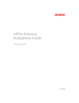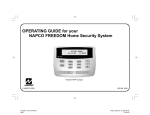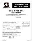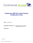
1
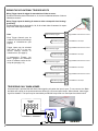
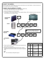
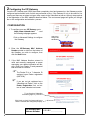
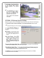
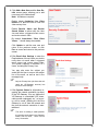
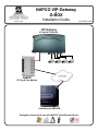
NAPCO VIP-Gateway
&
R
333 Bayview Avenue
Amityville, New York 11701
For Sales and Repairs, (800) 645-9445
For Technical Service, (800) 645-9440
Publicly traded on NASDAQ
Symbol: NSSC
© NAPCO 2006
G-BOX
Installation Guide
VIP-Gateway
4 Camera IP Module
Internet
G-BOX
IP Plug & Play Module
VideoAlert.net SERVER
Designed exclusively for use with NAPCO VideoAlert.net Server
COMPATIBLE
WI1436B.25 01/06
VIP-GATEWAY Features
VIP-GATEWAY SPECIFICATIONS
4 video inputs, accepts any analog CCTV camera.
1 channel video output, NTSC or PAL.
1 trigger input per channel to trigger transmission of video for archiving on
VideoAlert.net server. (Note: 1 additional trigger in and 1 additional
trigger out is available on the power supply connector assembly.)
Programmable trigger on video motion detection.
Built-in motion detection scan time x 4 channels: 1 second. (approx. 250
mS x channel)
14 seconds of pre-alarm images per channel.
Adjustable image size: 640x480, 320x240 and 160x120 Setup up through
active-X server application.
Dynamic IP support (without the need of any 3rd party addition or service)
via built InfoServer DNS technology.
RJ45 GATEWAY is designed for 10Mbps Ethernet networks. GATEWAY
connects to the network via UTP (Unshielded Twist Pair) Category 5
cable.
Power & Trigger I/O GATEWAY adopts unique RJ12 cable for power supply. The special featured RJ12 cable includes input/output (I/O) function. Simply connect the input/output cable to desire device and no
hardware jumper on camera is required.
Video out and video in 1 channel NTSC or PAL video output, can connect
with PC and televisions, 4 channel
NTSC or PAL video input available, turn analog video cameras into IP
cameras.
NTSC Local Video Output with Switching: Selectable “dwell time” via Web
interface for local viewing or distribution.
Local Video Output Latching - Video from cameras 1-4 may be latched to
the Video Output by shorting input triggers 1b - 4b respectively.
Transmission Protocol: UDP. UDP Port used: Port 80 or any above 1000.
Dimensions
4 7/8 x 8 1/4 x 1 1/2
(H x W x D), Inches
Input Voltage:
5VDC via 120VAV to 5VDC
Transformer (supplied)
Current:
600mA
(Transformer rating)
G-BOX SPECIFICATIONS
Dimensions
5 5/16 x 3 9/16 x 1 1/8
(H x W x D), Inches
Input Voltage:
9VDC via 120VAV to 9VDC
Transformer (supplied)
Current:
180mA Max (all 4 LAN ports in
use)
ORDERING INFORMATION
VIP-GatewayX:
Includes:
VIP-Gateway internet CCTV
adapter module
Power Adapter
3’ CAT5 cable.
G-BOX
Includes:
G-BOX Internet Interface for
VIP-Gateway.
Power Adapter
3’ CAT5 cable.
VIP-GatewayX/24: Kit Includes:
(1) VIP-GatewayX
(1) G-BOX
(24) month VideoAlert
Server service
Table of Contents
NAPCO Security Systems, Inc.
333 Bayview Avenue, Amityville, New York 11701
For Sales and Repair, call toll free: (800) 645-9445
For direct line to Technical Service, call toll free:
(800) 645-9440
Internet: http://www.napcosecurity.com
Windows ®, and the Windows logo are registered trademarks of Microsoft Corporation
Apple ® and the Apple logo are registered trademarks of Apple Computer, Inc.
Linux ® is a trademark of Linus Torvalds. The Linux penguin logo was created by Larry Ewing.
2
Features and specifications .............................. 2
System Overview ............................................... 3
Installation Overview.......................................... 4
Gateway Terminals and Connections................ 5
Wiring the Trigger Inputs.................................... 6
Armed Trigger Input ........................................... 6
Connecting to G-BOX & Internet........................ 7
G-BOX LED Indicators....................................... 7
Configuring the Gateway ................................... 8
Advanced Settings ............................................. 9
Account Activation ........................................... 12
Entering Subscriber Details ............................. 13
Video Inbox ...................................................... 14
Adding New Users ........................................... 15
Frequently Asked Questions............................ 16
NAPCO Limited Warranty ................................ 20
OVERVIEW OF THE VIDEOALERT.NET SYSTEM
The NAPCO VideoAlert is a system that allows remote video internet
monitoring of residential and light commercial properties. Its unique
subscription based account system provides the opportunity to realize
recurring revenue from typical CCTV video installations, The system is
comprised of the following three components:
The NAPCO VIP-GATEWAY is a module that converts any 4 analog CCTV
cameras into internet ready IP cameras. It provides video images with a
maximum of 640 x 480 lines of resolution that can be viewed through the
VideoAlert server on virtually any computer in the world at up to 5 fps. The
Gateway provides 4 input triggers that when activated, will prompt the
transmission of video clips to the VideoAlert.net server. It also has a local
video output that provides a sequenced video output of the 4 cameras. There
are also an additional 4 inputs that allow the user to lock in one of the
cameras to the local output. The Gateway provides (at no additional service
charge) dynamic IP support through the NAPCO InfoServer DNS server every 16 seconds the Gateway checks in with its DNS server to insure that
the DHCP IP address is always kept current.
The NAPCO G-BOX (Patents Pending), included in the VIP-GATEWAYX/24
kit, is an Internet Video accessory that allows the “Plug & Play” installation of
the NAPCO VIP-GATEWAY. Many other devices that allow direct connection
to the internet require re-configuration of the router, but not the G-BOX. The
G-BOX segments the network, automatically detects and properly forwards
the data intended for the VIP-GATEWAY or to the customer’s computer/
router, as required. The G-BOX is designed to be placed between the
broadband modem and router, and also functions as a router for cases where
the customer’s PC is the only device connected to the broadband modem.
The G-BOX provides 4 auto-sensing LAN ports for connection to the VIPGATEWAY and to the customer's PC, router or other equipment. This
revolutionary new device totally eliminates the need for TCP/IP and network
trained professionals for typical* VIP-GATEWAY installations, now allowing
standard alarm personnel to quickly and easily install these IP devices. The
G-BOX functions as both a DHCP client and server, to fit seamlessly into all
typical DHCP environments.
VIP-GATEWAY
G-BOX
BROADBAND
MODEM
Internet
VideoAlert.net
server
* a typical VIP-GATEWAY installation is connected to an
ALWAYS ON Cable or DSL Broadband modem.
The NAPCO VideoAlert.net server maintains VideoAlert accounts and allows
subscribers to view cameras connected to their VIP-Gateway from any
personal computer or web enabled cell phone. It is compatible with computers
running the Microsoft Windows ®, Apple ® and Linux ® operating systems
and is also compatible with any WAP enabled cell phone or mobile video
device. The server also automatically notifies the subscriber by email upon
receipt of triggered video events and archives them for viewing at a later time.
Each subscriber account provides 10Mb of storage, allowing the archiving of
about (15) 30 second video clips (15 sec pre-alarm and 15 sec post-alarm).
The server is designed to allow the customer to have complete control of their
account in regard to passwords, email addresses and other personal
information, freeing up the installation company from these routine
maintenance procedures. The login and video inbox screens may be private
labeled for the alarm company with logos or other artwork provided by the
alarm company.
Internet
3
INSTALLING, CONFIGURING AND ACTIVATING THE VIP-GATEWAY AND G-BOX
The installation and activation of the VideoAlert system has been designed to be “plug and play”, requiring no special
training or tools and no knowledge of TCP/IP or networking for typical installations. The primary installation steps depicted below are covered in detail on the following pages:
Install and wire all cameras and power supplies (not included).
1 Install the VIP-Gateway and G-BOX, following the wiring instructions on page 7.
Optional:
• If you plan on triggering the transmission of events from a security system, or other device, wire the Gateway trigger inputs as shown on page 6.
• If you wish to provide local video from the cameras to be viewed on a local monitor or be distributed
throughout the premises using a video distribution modulator, refer to video output latching instructions on
page 6.
2 Configure the VIP-Gateway on the VideoAlert server.
The Gateway must be configured on-line by simply going to the www.VideoAlert.net, and entering the MAC address number printed on the sticker on the bottom of the Gateway. If the customer plans to use the system only
for remote viewing of the cameras, there are no further configuration steps required. If using optional features,
these are all configured on-line:
Optional:
• If triggering video events, referring to page 11, be sure to program the VideoAlert server IP address under
the Security tab. Also, on page 10, under the Channel tab, change the trigger style from normally open to
normally closed, if necessary.
• If using the local video output from the cameras to be viewed on a local monitor or to be distributed
throughout the premises using a video distribution modulator, set the sequencer time on the Advanced
Settings, Main screen as described on page 9.
3 Activate the new VIP-Gateway account on the VideoAlert server.
Once the account is configured, it must be activated (personalized) for the customer. The system has been designed to allow the subscriber to have complete control of their account in regard to users, passwords, email addresses and other personal information. This self administration is described on pages 12 through 15 and also in
the User Guide, OI313 which should be given to the subscriber.
OVERVIEW OF TYPICAL VIP-GATEWAY / G-BOX RESIDENTIAL INSTALLATION
FROM BROADBAND
PROVIDER
BROADBAND
MODEM
CONTROL
PANEL
G-BOX
TRIGGER-IN FROM
CONTROL PANEL
(OPTIONAL)
ROUTER
VIP GATEWAY
CUSTOMER’S PC
LOCAL
MONITOR
(OPTIONAL)
4
CCTV CAMERAS INSTALLED IN RESIDENCE
1 INSTALLING AND WIRING THE VIP-GATEWAY
Descriptions of Terminals and Connections.
Power & Trigger I/O
Connect the supplied power supply to a 120VAC outlet and plug RJ14 style modular connector into Power/Trigger
port. The power adapter also includes a trigger input (see Trigger Inputs).
Video In
Connect BNC connectors from cameras to Video In connectors 1-4.
RJ-45 Input
Connect CAT5 cable from broadband modem or network to RJ-45 terminal.
Video Out (Optional)
To provide a video signal to local monitor or video distribution system, connect to video out terminal. The video out
will provide a sequenced output with programmable dwell time, adjustable through Advanced Settings button online
at VideoAlert.net. The video from the individual cameras 1-4 may be latched onto the Video Out output by activating
Trigger In terminals 1b through 4b respectively. The Video format may be set in the VideoAlert.net advanced Settings screen to either PAL or NTSC.
PAL - PAL (Phase Alternating Line) is a video standard used in many countries around the world. Countries such as the United Kingdom, The Netherlands and more use PAL as their video standard. When
a VHS, DVD or laserdisc is released with the PAL format, it can have a maximum resolution up to 625
lines with a vertical frequency of 50Hz. There are different types of PAL standards, one of which uses
a vertical frequency of 60Hz instead of 50Hz.
NTSC - NTSC (National Television System Committee) is another video standard also used in many
countries around the world. While it is not technically superior to PAL, it is more widely used thanks to
its use in the United States and a variety of other countries, such as Japan. When a VHS, DVD or laserdisc is released with the NTSC format, it can have a maximum resolution up to 525 lines with a vertical frequency of 60hz.
Trigger In (Optional)
The trigger in terminal provide two functions:
1. Trigger cameras 1-4 to transmit video clip to VideoAlert.net server.
2. Latch the video signal of cameras 1-4 to the video output.
Reset
Press the Reset button to set the VIP-GATEWAY back to its original factory default configuration. To operate, press
and hold the Reset button while unplugging the power cable. Keep reset button help down, plug in the power cable
and release button in a few seconds.
5
WIRING THE VIP-GATEWAY TRIGGER INPUTS
Wiring Trigger inputs for trigger for transmission of video to server:
Provide a momentary short on terminals 1a, 2a, 3a, 4a to initiate transmission of video to
VideoAlert.net server.
Wiring Trigger inputs for latching of camera to video out output for local viewing /
processing:
Provide a latching short on terminals 1b, 2b, 3b, 4b to latch video of cameras 1-4 respectively to the Video Output connector
Note:
N/O momentary trigger 1
Each Trigger Channel must be
enabled in the Advanced Settings
screens of VideoAlert.net (see
page 9).
N/O latching trigger 1
1A
1B
N/O momentary trigger
If programming Triggers, you
MUST program the VideoAlert
server IP address under the Security tab (see page 10).
N/O latching trigger 4
Latch Camera 3 to Video Output
4A
N/O momentary trigger 4
Trigger Camera 3 video transmission to server
3B
N/O latching trigger 3
Latch Camera 2 to Video Output
3A
N/O momentary trigger 3
Trigger Camera 2 video transmission to server
2B
N/O latching trigger 2
Latch Camera 1 to Video Output
2A
Trigger inputs may be switched
from N/O to N/C in in the Advanced Settings screens of
VideoAlert.net. (see page 9).
Trigger Camera 1 video transmission to server
Trigger Camera 4 video transmission to server
4B
-
Latch Camera 4 to Video Output
TRIGGERING ONLY WHEN ARMED
An armed input is provided that will allow video triggering only when the input is open. To use, connect the Black
and White wire inputs on the power transformer harness to a n/c armed panel output. When shorted, video triggering will be disabled. This input may be controlled by an RB1000 relay wired to a control panel as shown below.
CONTROL
PANEL
(+)
AUX
PWR
12V
(-)
(-)
(-)
PGM
RB1000
BLACK
RED
6
WHITE
BLACK
COM N/C N/O
CONNECT THE CAMERAS
Install the analog video cameras and run the camera coaxial cable to the Video Gateway. Connect the camera cables to the BNC video-in ports of VIP-Gateway.
CONNECT THE VIP-GATEWAY TO ROUTER
1.
2.
3.
4.
Power-down existing network devices (i.e. Cable Modem, Router, etc.).
Connect the Cable or DSL Modem to the G-Box WAN port.
Connect VIP-Gateway to any G-Box LAN port.
If necessary, you may connect existing PC to any available LAN port --OR--if customer has a router, connect the
router WAN port to any available LAN port.
VIP-GATEWAY
BROADBAND
MODEM
G-BOX
WAN
WAN
LAN1
LAN2
LAN3
LAN4
Note: G-BOX LAN Ports are auto-sensing. Customer’s devices or
VIP-Gateways may be plugged into any port.
If no router installed, connect PC
directly to the G-BOX LAN ports
CUSTOMER’S
ROUTER
WAN
LAN1
LAN2
LAN3
LAN4
CUSTOMER’S
PC
G-BOX LED INDICATORS
Indicator Color
5. Power Up all the devices. Several minutes may be required for the
DHCP sessions to take place.
6. Record the VIP-Gateway Mac Address (bottom label, example:
0009B5106763) which will be needed in the subsequent registration
steps:
Solid
Flashing
Power Green
Turns solid green
when power is
applied to device.
N/A.
Status Red
Turns solid red
when the device is
not working properly.
Connected and
linked to a Cable/
DSL Modem.
Turns green when
linked to a local
network.
WAN
Green
LAN 1
to
LAN 4
Green
Go to VIP-Gateway Configuration page 8.
Receiving/
Sending data
Receiving/
Sending data
7
2 Configuring the VIP-Gateway
Once the VIP-Gateway and G-BOX have been completely wired and powered up, the Gateway must be
configured and activated; both of which are performed on-line. If the Gateway is only to be used for live
viewing and there are no plans to trigger video events to the VideoAlert.net server, the only step required
is the registration of the MAC address described below. The next several pages will guide you through
the on-line configuration and activation process.
CONFIGURATION
1. To configure your new VIP Gateway, go to:
https://www.videoalert.net/
...and
the following webpage appears:
Click on Advanced Settings to configure
the Gateway
Click here to
configure the
VIP-Gateway
2. Enter the VIP-Gateway MAC Address
Number printed on label on the bottom of
the Gateway you wish to configure, then
click the Next button.
3. If the MAC Address Number entered is
valid, and currently unassigned, a screen
requesting your dealer information will display. Enter your Dealer ID and password
and click Next to continue.
The Dealer ID is a 7 character ID
assigned upon Dealer registration
(ABC1234).
If you are not yet registered as a
VideoAlert.net Dealer, click on the
Dealer Registration link, on bottom of www.videoalert.net screen.
To go directly to Subscriber
Activation (page 12), click here
Click Here! to check live image and insure
that the cameras are configured properly.
VIP Gateway MAC
0009B5 _ _ _ _ _ _
Address Number
8
4. The next screen that appears displays
a Live Viewer image received from
the VIP Gateway MAC Address
Number specified in the previous
screen.
f the VIP-Gateway is only to
be used for remote look-in,
there are no additional configuration steps required.
Turn to page 12 for Account
Activation
OPTIONAL: VIP-Gateway Advanced Settings
Right-click anywhere within the Live Viewer image window and a menu drop-down list will appear.
Click Special Functions, Advanced Settings and the Advanced Settings window will open:
Advanced settings may not be accessed via the alternative Live Viewer.
5. In the Advanced Settings window, Main tab, enter the following information:
MAC Address - Verify that the unique
MAC Address taken from the previous screen and displayed here is
correct.
Video Input Format - Select NTSC
(National TV Standards Committee)
or PAL (Phase Alternating Line).
Note: NTSC is the default value.
Changing selections requires your
PC be restarted before changes will
take effect.
Sequenced Video Output Dwell Time - Select a dwell time, in seconds, for the sequenced
video output to display each one of the four camera inputs.
Video Gateway Internal Time - You can select what method the VIP-Gateway will use to
update the day, date and time. To synchronize the VIP-Gateway with the existing PC,
check Use this PC Current Time to Update Internal Time.
Click Reload to revert to the original settings before changes were selected or click Save
to update and save the new settings.
9
6. Click the Channel tab to select options to customize image attributes:
Activate Motion Detect
external devices).
1
- Check to enable the camera to detect moving objects (to alert optional
Sensitivity Level - When Activate Motion Detect is enabled, set the sensitivity by clicking either the
Low, Med. or High radio button.
Images (Trigger) Buffer - Select the number of images to be stored in the pre-alarm and post alarm
buffers and to be sent to the VideoAlert.net server in the event of a trigger activation.
Brightness - Select the light level displayed on the video screen.
Contrast - Change the difference between the lightest and darkest areas displayed on the video screen.
Saturation - Increase to intensify each color displayed.
Hue - Select the predominant wavelength of color displayed.
Default - Click to display the original Brightness, Contrast, Saturation and Hue settings assigned to the
application before changes were specified.
Select Channel - Click to display the features associated with each video input.
Device - Check to select optional triggered output devices. Examples include relays to be triggered
when a specific event occurs or
Image Format - Select the desired resolution of the images to be sent to the VideoAlert.net server in the
event of a trigger input activation.
Click Reload to revert to the original settings before changes were selected or click Save to update and
save the new settings.
1
10
If video motion detection is enabled, ensure that the camera is not in an environment
that would cause the “run-away” transmission of multiple video clips to the server.
7. Click the Security tab to select options to customize data protection settings.
Trigger Receiver Server URL or IP - Enter the IP address or URL of the VideoAlert.net server
(69.20.70.164) or (www.videoalert.net) for the Gateway to send video to the VideoAlert.net server
when triggered.
Trigger Output - When the camera detects moving objects, or one of the (4) trigger inputs is activated,
the trigger output is activated, which may be used to trigger a zone on a security system, etc.. Enter
the duration of the trigger output signal (in seconds)., and the camera will continue to trigger the
device for the length of the time specified. Note: The trigger output signal is sent each time the
Manually Activate Trigger Output button is clicked.
LAG time to Start Guard - Specify the exit delay time (in seconds) allowing the exiting of the protected
area.
Activate Security Function - Click the radio button to select the Security Function type, either
Always or Daily. Select Always to enter security mode when the Trigger In or Motion
Detection functions are activated; select Daily to enter security mode at the specified Video
Gateway Internal Time (in 24-hour military time). See the Main tab, "Video Gateway Internal
Time" for more information.
11
3 Activating the VideoAlert.net account
Once the VIP-Gateway and G-BOX have been completely wired and powered up, and the system has
been configured, the VideoAlert.net account must be activated. These activation steps, described on the
next two pages have designed to be administered by the subscriber. To allow the subscriber to activate
their own account, provide them with the User Guide, OI313 included with the VIP-Gateway so they can
enter their personal information, such as passwords, email addresses, etc..
NEW ACTIVATION
1. To activate your new VIP Gateway
Video account, simply enter the following Internet address in your Web
browser:
https://www.videoalert.net/
...and the following webpage appears:
For new accounts, click on the
New Activation link, as shown in
image at right.
Click here to
register your
new account
2. In the section entitled "VIPGateway Activation", enter your
VIP Gateway MAC Address Number (supplied by your installer),
then click the Next button to start
your VIP Gateway Video service.
VIP Gateway MAC
0009B5 _ _ _ _ _ _
Address Number
12
3. In the section entitled "Subscriber
Details", type your name, address,
telephone number and other information in the appropriate fields as
shown in the image at right.
NOTE: All field descriptions marked
with an asterisk (*) must be completed, and are as follows:
•
•
•
•
First Name
Last Name
Telephone
Email address
4. In the section entitled "Security
Credentials", designate your own
unique User ID and Password to
be used for all future access to your
account.
Enter your Password twice (in the
Password Verification field), to
ensure it is typed correctly.
Check the box marked "Autodetect
'Best Video Viewer' for your PC and
Internet Connection" for the software
to automatically select the most efficient video viewer and connection
speed each time you logon.
Click Next to continue.
5. The section entitled "Confirmation"
verifies all information entered in
step 3 and 4.
Be sure to check the accuracy of
the information displayed, and if
changes are required, click the
Prev button to edit any previously
entered information.
When you are sure the information
displayed is correct, click the Update button to complete your new
account activation procedure.
If you forget your password, click the
"Forgot Your Password?" link on
the Subscriber Login screen and an
email with your password will be sent
to the email address entered in step
3.
13
6. Update is complete when the Subscriber
Login screen shown at right appears, indicating you have successfully activated
your new VideoAlert.net account, and you
can login at any time.
To login, enter your User ID (Username)
and Password selected in step 4, then
click Login to continue.
7. Upon login, the Video Inbox screen appears as shown in the image at right. For
new accounts, the Video Inbox will be
empty, as displayed in this image.
From here, you can
•
•
•
•
•
View the Live Viewer
View the Video Inbox
View User Settings)
View and modify Email Alert settings.
Logout
Click Live Viewer to view video screens
assigned to your VIP Gateway Video account.
8. Click Go Back to Video Inbox and then
click on User Settings and the next User
Settings screen appears. Any registered
user ID will be listed, together with other
account attributes, as displayed in the image at right.
Only the Primary User (the User that activated the VIP-Gateway account) has
access to User settings.
Edit a user by clicking the pencil and pad
icon on the right in the User Settings
screen (see User Detail screen below).
Delete a User by clicking on the garbage
can icon
14
9. Click Add a New User and the User Details screen opens, allowing you to add
new users in the fields shown.
Note: All fields are required.
Enable (check) Authorize Live Video
Review if to allow the user to view live
video sat any time.
Enable Receive Alerts and Review
Stored Videos to allow notify the User
via email when a triggered event occurs
and review stored video.
By default, Auto-detect “Best Video
Viewer...” should always be enabled.
Click Update to add the new user and
return to the previous screen, or click
Prev to cancel and return to the previous
screen.
10.Click Email Alert Settings to enter the
Email address of those Users you wish to
notify when via email when a triggered
event occurs and review stored video.
The system supports a maximum of 5
Users, including the Primary User.
You may also enter the subject you
would like the User to see on the subject
line of the email, as well as text in the
message body.
Only the Primary User (the User that activated the VIP-Gateway account) has
access to email settings.
11.Click System Status for information regarding the network availability (up-time)
of the VIP-Gateway. If for any reason the
VIP-Gateway is unavailable (ISP down,
cable modem unplugged, etc..), a log entry will be made, detailing the time the
Gateway is cut off from the network and
the time the network connection is reestablished.
This level of tracking is made possible
by recording each check-in the Gateway
makes with its DNS, which occurs
every 16 seconds.
15
NAPCO VideoAlert.net System Frequently Asked Questions
What software do I need to view live video on a Mobile phone or PDA?
Video Alert has built in support for WML and HTML on mobile devices. Any "data" enabled wireless device request is
automatically re-directed to the proper login page. Some PDA's (ie. Blackberry) require that Javascript and Image display be enabled.
No additional software or applets are needed.
Can I set up the Gateway to function as an off-premises Digital Video Recorder to record full time video?
No, the system is not set up for full time recording. It is designed to send 30 second video clips to the VideoAlert.net
server that are the result of triggered events that are transmitted by an event such as an alarm, the opening of a protected door, disarming of the system, etc.. If the server receives an inordinate volume of video streamed to an account,
it will automatically suspend the account for 24 hours and generate an email to the Dealer, informing them of the suspension. After 24 hours, the account will automatically be re-enabled.
I have a wireless router connected to my broadband modem. How can I keep my network settings after the GBOX is installed?
After the installation is completed, the G-BOX becomes your "primary" router. You can connect any PC or device on a
unused G-Box port (including your VoIP adapter). Remember: a second router is NOT required to share your internet
connection.
Advanced user note on avoiding IP conflicts: The G-BOX is factory configured IP is 192.168.8.1 and provides DHCP
server service on the range of 192.168.8.201, 192.168.8.20x and up.
Do I still need a router to share my internet connection after the ViP-Gateway and G-Box are installed?
After the installation is completed, the G-BOX becomes your "primary" router, you can connect any PC or devices on a
unused G-BOX port (including your VoIP adapter). If more ports are required, a "network switcher" can be installed on
any port for expansion.
After installing the G-BOX and the VIP-Gateway I lost my internet connection. Why?
Verify that your connection is indeed an ALWAYS ON service (ie. Cable ISP), then "power cycle" all your devices including your PC(s).
If your internet connection is provided by a DSL service, verify with your ISP that your connection is initiated by the
modem and not your PC or an existing router, if that is case, refer to “bridge mode” below.
My DSL modem is connected directly to my PC and must initiate the connection from the PC (PPPoE), how do I
setup the G-BOX to do this automatically?
First, locate your PPPoE User Id and Password, and then refer to “bridge mode” in the next question to allow the GBOX to this automatically initiate this connection for you. The G-BOX will also function as a router (share your internet
connection among all the Pc's) and maintain your DSL connection Always ON.
My modem and router are integrated into one unit, how do I install the VIP-Gateway and the G-BOX?
If the modem/router combo has a DMZ port or connection, connect the G-BOX to the DMZ port, then follow the installation instructions.
In some cases the modem/router "combo" has to be setup in "bridge mode". In this mode the G-BOX will provide all
the "routing services" and PPPoE (if required). Bridge mode, otherwise known as “pass through” will allow the modem/
router device to function as a modem and all routing functions will be performed by the G-BOX. Most of the modem/
router combos configuration are accessed via the web browser, just point your browser to the modem/router address
(note: a user/password maybe required), for example (some popular manufacturers and or models):
Linksys (most models): http://192.168.1.1
Westell: http://dslrouter or http://192.168.1.1
2Wire: http://homeportal or http://192.168.0.1
BritePort: http://192.168.1.1
A network configuration option is available. Make sure you follow the instructions and power cycle or reset the device if
necessary
16
High security areas - place a contact on the door of a special storeroom, cash room, etc.. If the door is opened,
video will be captured, sent to the server and archived, maintaining a video record of activity. The motion sensor
feature of the camera may also be used to trigger and event.
Summer / vacation home – monitor who accessing your vacation home while you are away. Each time the security
system is disarmed; video will be captured, sent to the server and archived, maintaining a video record of activity.
What is the exact sequence of events that occur upon a trigger?
1. An open occurs on the n/c trigger input of the device (VIP-Gateway or VCAM-I).
2. The device freezes the last 12 seconds of video (pre-alarm).
3. A connection to the VideoAlert.net server is established.
4. The device sends the pre-alarm video to the server and streams live video to the server up to a total of 30 seconds.
5. An email is sent to the customer, notifying them that a video alert alarm has occurred.
6. The customer clicks the link and they are soon viewing the video clip. If the customer would also like to view
live video, they can click on the View Live link and enter their password
Do I have to install any special software on the customer’s computer or cell phone so they can view video?
No, the customer can view their video through any computer running a Windows, Apple or Linux based operating system. They can also view video on any cell phone that has a built-in web browser, without the need to install any special applications.
What is required at the premises in order the install a VIP-Gateway?
The premises must have a broadband internet service, preferably an always-on service, such as DSL or cable modem
with an active internet account.
How much video can be stored in the user’s account?
Each User account has a volume limit of 10Mb, which equates to approx (15) 30 second video clips. The customer has
the option of deleting the clips after they are viewed. If they do not delete the clips, they will remain stored until the
10Mb capacity is reached, at which time they will be automatically deleted.
Can the customer view live video?
The customer can access their account at any time to view live video from their premises. Simply go to http://
www.videoalert.net/ , click on Live Viewer and enter the camera name and password to view the live video. There are
no limitations on how often or for how long the customer views their cameras.
How does the customer view archived video?
The customer can access their account at any time to view archived video. Simply go to http://www.videoalert.net/, enter the user ID and password to see a list of video clips, listed by time and date. To view any stored video, just double
click it. The customer also has the option of deleting each video clip, or downloading it to their hard drive.
Does the VIP-Gateway have a built in motion sensor?
The VIP-Gateway motion detection capability, with sensitivity adjustments and a time schedule. It can be armed to trigger an event upon motion detection.
What is the monthly fee for the Video Alert account?
The VIP-GatewayX/24 is sold with 24 months of VideoAlert.net service included in the purchase price.
Does the VIP-Gateway use Dynamic or Static IP Addresses?
The VIP-Gateway is designed to operate on a DHCP network. Every 16 seconds, the VIP-Gateway broadcasts a UDP
packet to a Domain Name Server (DNS) and identifies itself by name to the server. The server then compares the current device IP address to the one in the DNS database and automatically updates the IP address if it has changed.
Static IP Address, an IP address whose value does not change.
DHCP, Dynamic Host Configuration Protocol, a protocol for assigning dynamic IP addresses to devices on a
network. With dynamic addressing, a device can have a different IP address every time it connects to the network. DHCP also supports a mix of static and dynamic IP addresses.
DNS, Domain Name Server, an Internet service that translates domain names into IP addresses. Because domain names are alphanumeric, they're easier to remember. The Internet however, is really based on IP addresses. Every time you use a domain name, therefore, a DNS service must translate the name into the corresponding IP address. For example, the domain name NAPCOCAM01 might translate to 198.105.232.4.
17
I have a customized network environment (multiple routers, firewall, bridge, VoIP etc.) What should I know or do
about a VIP-Gateway installation?
G-Box factory configuration:
Local IP: 192.168.8.1
Auto DHCP client enabled (to obtain automatic IP address from broadband modem)
DHCP server enabled, range 192.168.8.20x and up
ViP-GatewayX/24:
G-Box DHCP enabled
For more advanced network installers and custom configuration, contact NAPCO Customer Support to request the
VIP-GatewayF/24, factory programmed with a fixed static IP.
Where are the disks, programs or software?
No software is provided, all the required applications are web enabled via www.VideoAlert.net. Internet Explorer with
ActiveX enabled (default security settings) is required to access the full featured Live Viewer.
What is the G-Box DHCP default range of IP addresses? What about ports?
The G-Box is factory programmed to serve IP addresses in the range of 192.168.8.201, 192.168.8.202, etc.
Our custom protocol assigns and expects a UDP connection on the port 8000 range, based on the assigned IP address
served to the VIP-Gateway: For example 192.168.8.201 will use port 8201.
My modem does not have an Ethernet (RJ45) port. How do I connect to the G-Box?
Most ISP's provide modems with RJ45 Ethernet ports (or both) with their service at no charge, please consult with your
ISP (Internet Service Provider).
The PC does not have Ethernet (RJ45), what happens now?
Some USB to Ethernet adapters are compatible with the G-BOX, even though an Ethernet port (adapter) is highly preferred to connect PC(s) to the G-BOX.
I am a network expert, do I really need the G-Box?
NAPCO can provide a version of the Gateway with a fixed static IP, the VIP-GatewayF/24, IP (192.168.1.10 and port
80). This version does not require the G-BOX, but the installer will have to make the appropriate changes to the existing network router to ensure the UDP port 80 is properly forwarded. Contact NAPCO Tech Support.
I have a VoIP (ie. Vonage) adapter router, where do I connect the adapter after the G-BOX is installed?
Any available port on the G-Box is fully compatible with standard IP network devices. Simply plug the VoIP router into a
G-BOX LAN port as described on page 7 and it will function properly. For technical reference the G-BOX router functionality is equivalent to a D-Link DI-604 series and Linksys BF series.
How do I signup as a NAPCO Video Alert Dealer?
To activate a Dealer account, the Dealer must go to http://www.videoalert.net/ and complete the on-line registration
form and then click submit. The Dealer will receive a confirmation email within 24 business hours with the admin login
and password needed to create new User accounts.
Do the IP modules and VideoAlert.net server support Pre and Post Alarm?
The NAPCO VCAM-I IP and VIP-Gateway transmit to the server approx. 12 seconds of pre-alarm (before trigger) and
18 seconds of post-alarm video for a total of 30 seconds.
How are the modules triggered to send Video Events?
The NAPCO VIP-Gateway sends compressed video clips to the NAPCO Video Alert server upon activation of the module’s trigger input(s). This trigger activation is accomplished by momentarily shorting a normally open input on the module. The camera will then transmit a video clip approx. 30 seconds long to the server. The VIP-Gateway may also be
triggered by the built-in motion sensor feature. Note that the trigger can be programmed to be always armed or armed
by a daily schedule.
Suggested events for triggering:
Latchkey Kids – Program the control panels to trigger the camera upon system disarm by kid’s codes. The camera
will capture video of the kids coming home, disarming system and locking the door behind them. The parents will
then be emailed a video alert notifying them that an event has occurred – all they have top do is click a link to view
the video for the ultimate peace of mind
18
UDP, User Datagram Protocol is connectionless protocol that offers a direct way to send and receive datagrams over an IP network. It's used primarily for broadcasting messages over a network.
Can a dealer re-register a Gateway to another user in cases where the User cancels or moves?
Yes – the Dealer has complete control over the account – he can terminate one user and re-program the Gateway to a
new user.
I have a customer who requires more than 4 cameras. Is it possible to connect multiple Gateways to one account ?
Yes – one account can monitor multiple gateways. In order to do this, you must contact Tech Support and they will
map the Gateways to a single account.
I can view VIP-Gateway, but the triggers no longer work after a while. Why?
The VideoAlert.net server has an overflow signal processing policy: If more than 20 signals (videos) are received from
the same IP address in any 30 minutes period, the VIP-Gateway is temporarily disabled by the server. Every 24 hours
a new cycle starts, resetting any previously denied VIP-Gateways. If a VideoAlert.net System Administrator detects an
anomaly (runaway system, etc.) this system is put into a Deny list and the Dealer Administrator that “owns” the account
is automatically contacted by email to resolve the situation ASAP.
When I click on the Live View, I only get a black screen.
Click on the link to the alternative Live Viewer just below the Live Viewer screen. If you are on the local network you
can right click on the black screen and choose direct connect and enter local IP address with port #. ie. 192.168.8.201
port 8201 or 192.168.8.202. port 8202
I am triggering the VIP-Gateway but am not getting video clips transmitted to the server.
Make sure that:
1. The security settings are enabled.
2. The white and black wires on the power supply harness are open.
3. The correct URL or server IP address is in the trigger field.
Note: If you have trip on motion enabled, camera will not record while you are in Live View.
19
NAPCO LIMITED WARRANTY
NAPCO SECURITY SYSTEMS, INC. (NAPCO) warrants
its products to be free from manufacturing defects in
materials and workmanship for thirty-six months
following the date of manufacture. NAPCO will, within
said period, at its option, repair or replace any product
failing to operate correctly without charge to the original
purchaser or user.
This warranty shall not apply to any equipment, or any
part thereof, which has been repaired by others,
improperly installed, improperly used, abused, altered,
damaged, subjected to acts of God, or on which any
serial numbers have been altered, defaced or removed.
Seller will not be responsible for any dismantling or
reinstallation charges.
THERE ARE NO WARRANTIES, EXPRESS OR
IMPLIED, WHICH EXTEND BEYOND THE
DESCRIPTION ON THE FACE HEREOF. THERE IS
NO EXPRESS OR IMPLIED WARRANTY OF
MERCHANTABILITY OR A WARRANTY OF FITNESS
FOR A PARTICULAR PURPOSE. ADDITIONALLY,
THIS WARRANTY IS IN LIEU OF ALL OTHER
OBLIGATIONS OR LIABILITIES ON THE PART OF
NAPCO.
Any action for breach of warranty, including but not
limited to any implied warranty of merchantability, must
be brought within the six months following the end of the
warranty period.
IN NO CASE SHALL NAPCO BE LIABLE TO ANYONE
FOR ANY CONSEQUENTIAL OR INCIDENTAL
DAMAGES FOR BREACH OF THIS OR ANY OTHER
WARRANTY, EXPRESS OR IMPLIED, EVEN IF THE
LOSS OR DAMAGE IS CAUSED BY THE SELLER'S
OWN NEGLIGENCE OR FAULT.
In case of defect, contact the security professional who
installed and maintains your security system. In order to
exercise the warranty, the product must be returned by
the security professional, shipping costs prepaid and
insured to NAPCO. After repair or replacement, NAPCO
assumes the cost of returning products under warranty.
NAPCO shall have no obligation under this warranty, or
otherwise, if the product has been repaired by others,
improperly installed, improperly used, abused, altered,
damaged, subjected to accident, nuisance, flood, fire or
acts of God, or on which any serial numbers have been
altered, defaced or removed. NAPCO will not be
responsible for any dismantling, reassembly or
reinstallation charges.
This warranty contains the entire warranty. It is the sole
warranty and any prior agreements or representations,
whether oral or written, are either merged herein or are
expressly cancelled. NAPCO neither assumes, nor
20
authorizes any other person purporting to act on its
behalf to modify, to change, or to assume for it, any
other warranty or liability concerning its products.
In no event shall NAPCO be liable for an amount in
excess of NAPCO's original selling price of the product,
for any loss or damage, whether direct, indirect,
incidental, consequential, or otherwise arising out of any
failure of the product. Seller's warranty, as hereinabove
set forth, shall not be enlarged, diminished or affected by
and no obligation or liability shall arise or grow out of
Seller's rendering of technical advice or service in
connection with Buyer's order of the goods furnished
hereunder.
NAPCO RECOMMENDS THAT THE ENTIRE SYSTEM
BE COMPLETELY TESTED WEEKLY.
Warning: Despite frequent testing, and due to, but not
limited to, any or all of the following; criminal tampering,
electrical or communications disruption, it is possible for
the system to fail to perform as expected. NAPCO does
not represent that the product/system may not be
compromised or circumvented; or that the product or
system will prevent any personal injury or property loss
by burglary, robbery, fire or otherwise; nor that the
product or system will in all cases provide adequate
warning or protection. A properly installed and
maintained alarm may only reduce risk of burglary,
robbery, fire or otherwise but it is not insurance or a
guarantee that these events will not occur.
CONSEQUENTLY, SELLER SHALL HAVE NO
LIABILITY FOR ANY PERSONAL INJURY, PROPERTY
DAMAGE, OR OTHER LOSS BASED ON A CLAIM THE
PRODUCT FAILED TO GIVE WARNING. Therefore, the
installer should in turn advise the consumer to take any
and all precautions for his or her safety including, but not
limited to, fleeing the premises and calling police or fire
department, in order to mitigate the possibilities of harm
and/or damage.
NAPCO is not an insurer of either the property or safety
of the user's family or employees, and limits its liability
for any loss or damage including incidental or
consequential damages to NAPCO's original selling
price of the product regardless of the cause of such loss
or damage.
Some states do not allow limitations on how long an
implied warranty lasts or do not allow the exclusion or
limitation of incidental or consequential damages, or
differentiate in their treatment of limitations of liability for
ordinary or gross negligence, so the above limitations or
exclusions may not apply to you. This Warranty gives
you specific legal rights and you may also have other
rights which vary from state to state.