1
®
Caution:
Read and follow
all Safety Rules
and instructions
Before Operating
Th=s Eqmpment
o AssembUy
Operation
Customer ResponsibiUities
e Service and Adjustments
Repair Parts
iii ii ii
, ,lllll,
i ii iiill ill,,i
Sears, Roebuck
illll
and Co., Hoffman
Estates, IL 60179 U.S.A.
SAFETY RULES
Safe Operation
Practices
for Walk-Behind
TRAINING
.
=
-
Read the Owner's Manual carefully Be thoroughly
familiar with the controls and the proper use of the
equipment. Know how to stop the unit and disengage
the controls quickly_
Never allow children to operate the equipmenL Never
allow adults to operate the equipment without proper
instruction_
Keep the area of operation dear of all persons, pa rticulady small children, and pets
PREPARATION
=
o
o
o
°
•
o
•
Thoroughly inspect the area where the equipment is to
be used and remove ait foreign objects.
Disengage all clutches and shift into neutral before
starting the engine (motor')..
Do not operate the equipment without wearing adequate outer garments. Wear footwear that will improve footing on slippery surfaces.
Handle fue! with care; it is highly flammable.
Use an approved fuel container
Never add fuel to a running engine or hot engine
FiNfuel tank outdoors with extreme care. Never fill fuel
tank indoors,
Replace gasoline cap securely and clean up spilled
fuel before restarting
Use extension cords and receptacles as specified by
the manufacturer for all units with electric drive motors
or electric starting motors.
Never' attempt to make any adjustments while the
engine (motor) is running (except where specifically
recommended by manufactureO=
OPERATION
=
=
°
=
=
=
.
o
=
o
Do not put hands or feet near or under' rotating parts.
Exercise extreme caution when operating on or:CreSSing gravel drives, walks, or roads. Stay alert for hidden
hazards or traffic. Do notcarry passengers.,
After striking a foreign object, stop the engine (motor),
remove the wire from the spark plug, thoroughly inspect the tiller for any damage, and repair the damage
before restarting and operating the titler.
Exercise caution to avoid slipping or failing.
if the unit should start to vibrate abnormally, stop the
engine (motor) and check immediately for the cause
Vibration is generally a warning of trouble.
Stop the engine (motor) when leaving the operating
position°
Take all possible precautions when leaving the machine unattended.
Disengage the tines, shift into
neutral, and stop the engine
Before cleaning, repairing, or' inspecting, shut off the
engine and make certain all moving parts have stopped..
Disconnect the spark plug wire, and keep the wire
away from the plug to prevent accidental starting,
Disconnect the cord on electric motors.
Do not run the engine indoors; exhaust fumes are
dangerous.
Never operate the tiller without proper guards, plates,
or other safety protective devices in place.
°
=
o
=
o
•
.
Powered
.
°
o
Tillers
Keep chitdren and pets away.
Do not overload the machine capacity by attempting to
till too deep at too fast a rate.
Never operate the machine at high speeds on slippery
surfaces. Look behind and use care when backing
Never allow bystanders near the uniL
Use only attachments and accessories approved by
the manufacturer of the tiller (such as wheel weights,
counterweights, cabs, and the like)
Never operate the tiIler Without good visibility or light
Be careful when tilling in hard ground The tines may
catch in the ground and propel the tiller forward If this
occurs, let go of the handlebars and do not restrain the
machine
MAINTENANCE
.
Rotary
AND STORAGE
Keep machine, attachments, and accessories in safe
working condition.
Check shear pins, engine mounting bolts, and other
bolts at frequent intervals for proper tightness to be
sure the equipment is in safe working condition.
Never store the rnachine with fuel in the fuel tank inside
a building where ignition sources are present, such as
hot water and space heaters, clothes dryers, and the
like. Allow the engine to cool before storing in any
enclosure.
Always refer to the operator's guide instructions for
important details if the tiller is to be stored for an
extended period.
- IMPORTANT
-
CAUTIONS, 1MPORTANTS, AND NOTES ARE A MEANS
OF ATTRACTING ATTENTION TO IMPORTANT OR
CRITICAL INFORMATION IN THIS MANUAL
IMPORTANT: USED TO ALERT YOU THAT THERE IS A
POSSIBILITY OF DAMAGING THIS EQUIPMENT
NOTE:
Gives essential information that will aid you to
better understand, incorporate, or execute a particular set
of instructions.
Look for this symbol to point out important safety precautions. It means
CAUTION!!! BECOME ALERT!!! YOUR
SAFETY iS INVOLVED.
CAUTION:
Always disconnect spark
plug wire and place wire where it cannot contact spark plug in order to prevent accidental starting when setting
up, transporting, adjusting or making
repairs.
_u,
HIIHulllHi
II
& WARNUNG
&
The engine exhaust
from this product
contains chemicals known to the State of California to cause cancer, birth defects,
or other
reproductive
harm.
CONGRATULATIONS
on your purchase of a Sears Tiller,
It has been designed, engineered and manufactured to
give you the best possible dependability and performance.,
PRODUCT
Should you experience any problems you cannot easily
remedy, please contact your nearest authorized Sears
Service Center/Department
We have competent, welltrained technicians and the proper tools to service or repair
this unit.,
P_ease read and retain this manual,, The instructions will
enable you to assemble and maintain your tiller properly,
Always observe the "SAFETY RULES".
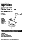
MODEL
NUMBER
SPECIFICATIONS
HORSEPOWER:
5 0 HP
DISPLACEMENT:
&03 cu. in,
GASOLINE CAPACITY:
3 Quarts
Unleaded Regular
OIL (API-SFISG):
(CAPACITY: 20 oz,)
SAE 30 (Above 32°F)
SAE 5W-30 (Below 32°F)
SPARK PLUG :
(GAPi ,030")
Champion RJt9LM
(STD361458)
9t7.295451
SERIAL
NUMBER
MAINTENANCE
AGREEMENT
A Sears Maintenance Agreement is available on this prod_
uct. Contact your nearest Sears store for details°
DATE OF
PURCHASE
THE MODEL AND SERIAL NUMBERS WILL BE
FOUND ON THE MODEL PLATE ATTACHED TO
THE RIGHT HAND ENGINE BRACKET,
YOU SHOULD RECORD BOTH SERIAL NUMBER
AND DATE OF PURCHASE AND KEEP tN A SAFE
PLACE FOR FUTURE REFERENCE,
CUSTOMER
RESPONSIBILITIES
o
Read and observe the safety rules°
•
Follow a regular schedule in maintaining, caring for and
using your tiller,
Follow the instructions
under the "Customer
Responsibilities" and "Storage" sections of this Owner's
Manua!,
•
[
IMPORTANT"
THIS UNIT IS EQUIPPED WITH AN INTERNAL COMBUSTION
ENGINE AND SHOULD NOT BE USED ON
OR NEAR ANY UNIMPROVED
FOREST-COVERED,
BRUSH-COVERED
OR GRASS COVERED
LAND UNLESS THE
ENGINE'S
EXHAUST
SYSTEM tS EQUIPPED WITH A SPARK ARRESTER
MEETING APPLICABLE
LOCAL OR STATE
LAWS (IF ANY)
IF A SPARK ARRESTER
IS USED, IT SHOULD BE MAINTAINED
IN EFFECTIVE WORKING ORDER BY
THE OPERATOR
IN THE STATE OF CALIFORNIA
THE ABOVE IS REQUIRED
BY LAW (SECTION 4442 OF THE CALIFORNIA
PUBLIC
RESOURCES
CODE).
OTHER STATES MAY HAVE SIMILAR LAWS.
FEDERAL LAWS APPLY ON FEDERAL LANDS.
SEE YOUR SEARS AUTHORIZED
SERVICE CENTER
FOR SPARK ARRESTER
REFER TO THE REPAIR
PARTS
SECTION OF THIS MANUAL FOR PART NUMBER
n ,u i i
, i n
LIMITED TWO YEAR WARRANTY
ON CRAFTSMAN
TILLER
For two (2) years from date of purchase, when this Craftsman Tiller is maintained, lubricated, and tuned up
according to the operating and maintenance instructions in the owner's manual, Sears will repair free of charge any
defect in material or workmanship.
This Warranty does not cover:
•
Expendable items which become worn during normal use, such as tines, spark plugs, air cleaners and belts,,
.
Repairs necessary because of operator abuse or negligence, including bent crankshafts
maintain the equipment according to the instructions contained in the owner's manual.
•
If this Craftsman Tiller is used for commercial or rental purposes, this Warranty applies for only thirty (30) days
and the failure to
from the date of purchase,
WARRANTY SERVICE IS AVAILABLE BY RETURNING THE CRAFTSMAN TILLER TO THE NEAREST SEARS
SERVICE CENTER/DEPARTMENT
IN THE UNITED STATES° THIS WARRANTY APPLIES ONLY WHILE THIS
PRODUCT IS tN USE IN THE UNITED STATES,,
This Warranty gives you specific legal rights, and you may also have other rights which vary from state to state
SEARS, ROEBUCK AND CO. D/817WA, HOFFMAN ESTATES, IL 60179
..............
i ii i lul,n,
i ilu,,,ll
i itoni
i=,
"N"I,HUlmHI
......................
"TABLE OF CONTENTS
SAFETY RULES ...........................................................
2
CUSTOMER RESPONSIBILITIES ..................... 3, 12-14
PRODUCT SPECIFICATIONS ......................................
3
WARRANTY ...................................................................
3
ACCESSORIES .............................................................
5
ASSEMBLY ...............................................................
6-7
OPERATION ............................................................
8-11
MAINTENANCE SCHEDULE .....................................
12
SERVICE & ADJUSTMENTS ................................ 14-17
STORAGE ...................................................................
18
TROUBLESHOOTING .................................................
19
REPAIR PARTS-TILLER .......................................
20-25
REPAIR PARTS-ENGINE ......................................
26-30
SERVICE/PARTS ORDERING .................... Back Cover
9NDEX
R
A
Engine ConL:
Accessories .................................................
5
Repair Parts
Repair Parts ........................ 26-30
Tiller. ................................... 20-24
Adjustments:
Spark Plug ............................................
14
Engine
26-30
Carburetor .....................................17
Starting
10
Rules
for
Safe
Operation
....................2
Depth Stake .................................. 9
Stopping ..............................................
9
Handle Height ................................
14
Storage .........................................18
Tines ...............................................
14-15
S
Winter Operation ..................... !3
V-Belt ...............................................
16
Service & Adjustments:
Wheels ....................................................
9
F
Carburetor .................................. 17
Air Cleaner ..............................................
13
Handle Height ..............................14
Fuel:
Tines ..............................................
t4-15
Filling Tank ....................................
10
B
V-Belt ......................................
16
Storage .................................... 18
Wheels .............................................9
Belt, V-:
Type ........................................... 10
Service:
Belt Guard ........................................
17
Finish:
Repair' Parts ...................................
21
Repair Parts ..............................
20-30
Maintenance .......................................
14
Service Record ...............................
12
V-Belt Replacement ................ 16
Spark
Plug:
H
C
Gap .......................................................
3
Handle:
Maintenance .............................. 14
Cooling System ....................................
13
Height Adjustment ........................
14
Storage:
Controls:
Repair Parts ............................. 20
Fuel System .............................. 18
Choke ...............................................
8
Tiller ..................................................
18
Throttle ..................................................
8
L
Tines .............................................. 8
Lubrication:
T
Cultivating ...............................................
11
Lubrication Chart ........................12
Tilling
.........................................................
9,11
Customer' Responsibilities:
Engine ................................................
13
Tines:
Air Cleaner. ....................................
13
Cooling System ........................ 13
Arrangement ...........................14-15
Finish ..............................................
14
Operation ................................................
9
Muffler:
Maintenance Schedule ................
12
Repair Parts .................................23
Maintenance .............................................
14
Muffler .......................................... 14
Replacement ............................ 15
Spark
Arrester
.............................
3
Oil Change ................................ 13
Transmission:
Spark Plug ................................ 14
Maintenance ...................................
14
0
Transmission ..................................
14
Repair Parts ...................................
24
Oil:
Troubleshooting ...........................................
19
D
Level .......................................
10
Transporting .........................................10
Type ................................................
10,13
Depth Stake:
Operation:
Adjustment ................................. 9
W
Repair Parts .......................................
22
Cultivating ......: .................................
11
Warranty ..............................................................
3
Fill Fuel Tank .......................... 10
Wheels:
E
Starting Engine ......................... !0
Stopping Tines & Engine ..............
9
Adjustments .............................
9
Engine:
Tilling .......................................................
9
Repair
Parts
...................................
22
Air Cleaner ....................................13
Tilling Hints ....................................
11
Cooling System ............................13
Tine Operation .......................... 9
Fuel Type .....................................10
Transporting Tiller ..................... 10
Lubrication ....................................13
Winter Operation. ...........................
13
Oil Level ..................................................
10
Oil Type .....................................
10,13
...................................
.................................................
= ==
..................
, =H......
=,=,
_
.................
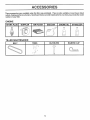
These accessories were available when the tiller was purchased° They are also available at most Sears Retail
outlets, Catalog and Service Centers. Most Sears Stores can order repair parts for you when you provide the model
number of your tiller,
ENGINE
SPARK
PLUG
MUFFLER
AIR FILTER
GAS CAN
ENGINE
01L
STABILIZER
._,,,,
TILLER
MAINTENANCE
,,,,,,,,
BELT
........,, ,i ,,,,,,p,.
TINES
CLEVIS PIN
HAIRPIN
CLIP
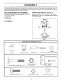
ASSE
LY
Your new tiller has been assembled at the factory with exception of those parts left unassembled for shipping purposes To
ensure safe and proper' operation of your tiller all parts andhardware you assemble must be tightened securely. Use the
correct tools as necessary to insure proper tightness.
TOOLS REQUIRED
FOR ASSEMBLY
A socket wrench set wilt make assembly easier
wrench sizes are listed,
OPERATOR'S
POSITION
(See Fig. 1)
When right or' left hand is mentioned in this manual, it
means when you are in the operating position (standing
behind tiiler handles).
Standard
(1) Utility knife
(1) Screwdriver
FRONT
(1) Pair' of pliers
(2) 1/2" wrenches
LEFT
IGHT
OPERATOR'S
POSITION
FIG. 1
CONTENTS
OF HARDWARE
PACK
U
(1) Manual
(1) Plastic Cable Clip
(1)ClevisPin
Q
(2) Carriage Bolts 5/16-18 UNC x 2-1/2
(1) Cotter Pin
®
(1) Washer
9/32 x 1/2 x 14 Gauge
(1) Reverse Rod Bracket
®
©
1) Bushing
(2) Flange Locknuts
5/16-18 UNC
UUl,,,ll
Q
J rrl!!lili iliJiiliaiiii itilirilii!
(2) Hex Bolts 5/16-18 x 1_1/4
(2) Hex Nuts 5/16-18
6
(2) Lock Washers
5/16
, =.........
n,=,=r,qrl=
..............................
UNPACK
i,u
CARTON
=
nn,,,,H,
,= =,r, u,
TINE CONTROL
staples when handling or disposing of
CAUTION:
Be careful
of exposed
ca,oning material.
! &
....
!
t
I
CABLE
HANDLE MOUNT
IMPORTANT:
WHEN UNPACKING ANDASSEMBL]NG
TILLER, BE CAREFUL NOT TO STRETCH OR KINK
CABLE(S),,
•
•
Cut cable ties securing handle column.
Slide handle column onto handle mount,
.
Remove alt packing from carton, Hardware pack is
found in folded cardboard packing.
ASSEMBLE
•
HANDLE
(See Fig. 2)
Slide reverse red through hole in reverse rod bracket
as shown_
•
Slide bushing over lower reverse rod and snap into
bracket hoteo
NOTE: Make sure tine control cable is routed in front of
reverse rod bracket.
•
Attach reverse rod bracket to handle column using two
(2) carriage bolts and two (2) flange Iocknuts and
tighten securely,
TINE CONTROL
.
Cut away carton,
-
Insert plastic cable dip into hole in handle column
o
Route tine control cable through plastic cable clip on
handle column.
o
Cut cable ties secu ring tiller to skid Remove tiller from
skid by pulling backwards.
ASSEMBLE
•
REVERSE
ROD (See
STAKE
REVERSE
ROD
BR
ASSEMBLY
Loosen Nut "A"
o
Insert stake support between engine bracket hafves
with stake spring down
°
Bolt stake support to engine brackets with bolts, lock
washers and nuts. Tighten securely Tighten nut "A"o
=BUSHING
FLANGE
LOCKNUTS
LOWER
REVERSE ROD
FIG. 2
ENGINE BRACKET
_,LVES
Depth stake must move freely,, If it does not, loosen
support bolt,
HANDLE
HEIGHT
DEPTH STAKE
Handle height may be adjusted to better suit operator
(See "HANDLE HEIGHT" in the Service and Adjustments section of this manual).
TILLING
o
CLEVIS
PIN
Fig. 2)
.
°
CABLE
CARRIAGE
Secure upper reverse rod to lower reverse rod using
clevis pin, washer and cotter pin_
INSTALL DEPTH
(See Fig. 3)
=
CABLE
WIDTH
Tilling width may be adjusted to better handle your
•
t I1ng
cond " t ' ons (See "FINE ARRANGEMENT J_ i n the
Service and Adjustments section of this manual),
DEPTH
STAKE
TINE OPERATION
=
Check tine operation before first use. (See "TINE
OPERATION CHECK" in the Service and Adjustments
section of this manual).
SUPPORT BOLT
HEX BOLTS,
LOCK WASHERS, AND HEX NUTS
FIG. 3
7
OPERATION
KNOW YOUR
TILLER
READ THIS OWNER'S MANUAL AND SAFETY RULES BEFORE OPERATING
YOUR TILLER.
Compare the illustrations with your tiller to famitiarize yourself with the location of various controls and adjustments.
this manual for future reference,
Save
These symbols
meaning.
their
may appear on your Tiller or in literature
supplied with the product.
Learn and understand
\
CAUTION
OR WARNSNG
•
i
,,
REVERSE
FORWARD
ENGINE
ON
ENGINE
OFF
FAST
SLOW
RUN
CHOKE
FUEL
OIL
STOP O
i, ,u ...................................................................
TINE
TtNE CONTROL
CHOKE CONTROL
THROTTLE
CONTROL
DEI
T|NE SHIELD
RECOIL STARTER HANDLE
O
\
FIG. 4
MEETS ANSI SAFETY
REQUIREMENTS
Sears tillers conform to the safety standards of the American National Standards Institute,
FORWARD TINE CONTROL - Engages tines in forward
direction,
REVERSE TINE CONTROL - Engages tines in reverse
direction°
CHOKE CONTROL - Used when starting a Cold engine
THROTTLE CONTROL - Controls engine speed°
DEPTH STAKE - Controls forward speed and the depth at
which the tiller will dig,
RECOIL STARTER HANDLE - Used to start the engine.
,'
i=!
=, u
==,,i,,n,H
,
OPERATION
=ulln
i
The operation of any tiller can result in foreign objects thrown into the eyes, which can
result in severe eye damage.
Always wear safety glasses or eye shields before starting
your tiller and while tilling. We recommend a wide vision safety mask over the spectacles
or standard safety glasses.
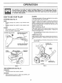
HOW TO USE YOUR TILLER
TILLING
STOPPING
The speed and depth of tilling is regulated by the position
of the depth stake and wheel height°
(See Fig. 5)
The depth stake should always be below the wheels for
digging° It serves as a brake to slow the tiller's forward
motion to enable the tines to penetrate the ground Atso,
the more the depth stake is lowered into the ground the
deeper the tines will dig,
TINES
o
Release forward tine control to stop forward movement,,
.
Release reverse tine control to stop reverse movement,
DEPTH STAKE (See Fig° 6)
ENGINE
-
Move throttle control to "STOP" position.
o
Never use choke to stop engine
REVERSE TINE CONTROL
Adjust depth stake by removing the hairpin clip and clevis
pin., Change depth stake to desired position, Replace the
clevis pin and hairpin clip,
o
FORWARD TtNE CONTROL
"OFF" (UP} POSITION
For normal tilfing, set depth stake at the second or thhd
hole from the top
WHEELS (See Fig. 6)
Adjust wheels by removing the hairpin clip and clevis pin
Change wheel position., Replace the hairpin clip and clevis
pin_
•
For normal tilling, set wheels at the second or third hole
from the top,
HAIRPIN CLIP
AND CLEVIS PIN
FORWARD TINE CONTROL
"ON" (DOWN) POSITION
DEPTH
STAKE
CHOKE
CONTROL_
CONTROL
HAIRPIN CLIP
AND CLEVIS PIN
WHEEL
FIG, 6
FIG. 5
TINE OPERATION
(See Fig. 5)
FORWARD
•
Squeeze forward tine control to handle.
REVERSE
°
With forward tine control in "OFF" (up) position, pull
back and hold reverse tine control,,
9
TRANSPORTING
ADD GASOLINE
YOUR TILLER
.................................
=
Fill fuel tank,. Use fresh, clean, regular unleaded
gasoline_ (Use of leaded gasoline will increase carbon
and lead oxide deposits and reduce valve life)
IMPORTANT: WHEN OPERATING IN TEMPERATURES
BELOW 32°F (0oC), USE FRESH, CLEAN, WINTER GRADE
GASOLINE TO HELP INSURE GOOD COLD WEATHER
STARTING
=
ing, allow tiller engine and muffler to
cool. Disconnectsparkplugwire.
Drain
CAUTION:from
Before
lifting or transportgasoline
fuel tank.
AROUND THE YARD
o
Tip depth stake forward until it is held by the stake
spnng.
Push tiller handles down, raising tines off the ground.
=
Push or pull tiller to desired focation.
WARNING:
Experience indicates that alcohol blended
fuels (called gaseho] or using ethanol or methanol) can
attract moisture which leads to separation and formation of
acids during storage° Acidic gas can damage the fuel
system of an engine while in sto_age, To avoid engine
problems, the fuel system should be emptied before
storage of 30 days or longer. Drain the gas tank, start the
engine and let it run until the fuel lines and carburetor are
empty, Use fresh fuel next season° See Storage section
of this manual for additional information. Never use engine
or carburetor cleaner products in the fuel tank or permanent
damage may occur
AROUND TOWN
o
.
Disconnect spark plug wire.
Drain fuel tank°
=
Transport in upright position to prevent oil leakage.
BEFORE
STARTBNG ENGUNE
• Ju_,=,1,1N=
IMPORTANT:
BE VERY CAREFUL NOT TO ALLOW
DIRT TO ENTER THE ENGINE WHEN CHECKING OR
ADDING OIL OR FUEL, USE CLEAN OIL AND FUEL AND
STORE
IN
APPROVED,
CLEAN,
COVERED
CONTAINERS USE CLEAN FILL FUNNELS.
FILL ENGINE
WITH OIL (See Fig. 7)
-
With engine level, remove engine oil filler plug.
-
Fill engine with oil to point of overflowing. For approxi' see " PRODUCT SPECIFICATIONS "on
mate capacity
page 3 of this manual.
Tilt tiller back on its wheels and then re-level
°
Check oil level,, Refill to point of overflowing if necessary. Replace oil filler plug.
=
For cold weather operation you should change oil for
easier starting (See "OIL VISCOSITY CHART" in the
Customer Responsibilities section of this manual).
•
CAUTION: Fill to within 1/2 inch of top
of fuel tank to prevent spills and to
allow for'fuel expansion, If gasoline is
accidentally
spilled,
move machine
away from area of spill. Avoid creating
any source of ignition until gasoline
vapors |lave disappeared.
Do not overfill. Wipe off any spilled oil
or'fuel. Do not store, spill or use gasoline near an open flame.
TO START
i _
_
ENGINE
(See Fig. 8)
CAUTION: Keep tine control in "OFF"
position when starting engine.
When starting engine for the fh'st time or if engine has run
out of fuel, itwill take extra pulls of the recoil starter to move
fuel from the tank to the engine.
To change engine oil, see the Customer Responsibilities section of this manual,
o
o
.
Make sure spark plug wire is properly connected
Place throttle control in "FAST" position,
With engine fully choked, grasp recoil starter handle
with one hand and grasp tilter handle with other hand,
Pull rope out slowly until engine reaches start of compression cycle (rope will pufl slightty harder at this
point),
Pull recoil starter handle quickly
Do not let starter
handle snap back against starter Repeat if necessary
in half choked position
o When engine starts, stowly move choke control to
"RUN" position as engine warms up_
NOTE: A warm engine requires less choking to start
°
Move throttle control to desired running position
=
Allow engine to warm up for a few minutes before
engaging tines,
NOTE: If at a high altitude (3000 feet) or in cold temperatures (below 32°F), the carburetor fuel mixture may need to
be adjusted for best engine performance, See "TO ADJUST CARBURETOR" in the Service and Adjustments
section of this manual
OIL
FILLER
PLUG
FIG, 7
NOTE: ifengine does not start, see troubleshooting
10
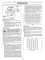
points_
You will find tilling much easier if you leave a row
untilled between passes. Then go back over the entire
area at right angles (See Fig. 9)..There are two reasons
for doing this First, wide turns are much easier to
negotiate than about-faces Second, the tiller won't be
pulling itself, and you, toward the row next to it
SPARK
.
PLUG
L'_
cHOKE
_I
CONTROL
Set depth stake and wheel height for shallow tilling
when working extremely hard soil or sod. Then work
across the first cuts at normal depth..
I1
¢_-
_
<-
<-.
<-
÷
÷J¢_
[.' I"_1I€i t'"ti '1€'1I€I !_l t_f 151l't!
RECOIL STARTER
HANDLE
_. ÷
÷
÷
-e,-
-_
÷
_
,.?
FIG. 8
BREAKING
IN YOUR TILLER
i I_'1 I_,1!'t'l I_1 I'i'l 1_,1I_I 1_I I_'l -
Break-in your belt(s), pulleys and tine control before you
actually begin tilling
•
Start er_gine, tip tines off ground by pressing handles
down and engage tine control to start tine rotation..
Allow tines to rotate for five minutes
°
Check tine operation and adjust if necessary. See
"TINE OPERATION CHECK" in the Service and Adjustments section of this manual.
TILLING
t, '1 I ,t 1-I'1I€I
CULTIVATING
Cultivating is destroying the weeds between rows to prevent them from robbing nourishment and moisture from
the plants. At the same time, breaking up the upper Iayer
of soil crust will help retain moisture in the soil Best
digging depth is 1" to 3"
CAUTION: Until you are accustomed to
handling your tiller, start actual field
use with throttle in slow position (midway between "FAST" and "IDLE").
o You wi!l probably not need to use the depth stake.
Begin by tipping the depth stake forward until it is held
by the stake spring.
To help tiller move forward, lift up the handles slightly (thus
lifting depth stake out of ground) To slow down the tiller,
press down on handles
° Cultivate up and down the rows at a speed which will
allow tines to uproot weeds and leave the ground in
rough condition, promoting no further growth of weeds
and grass (See Fig. 10)
tfyou are straining or tiller is shaking, the wheels and depth
stake are not set properly in the soil being tilled The proper
setting of the wheels and depth stake is through trial and
error and depends upon the soil condition_ (The harder or
wetter the ground, the slower the engine and tine speed
needed. Under these poor conditions, at fast speed the tiller
will run and jump over the ground).
A properly adjusted tiller will dig with little effort from the
operator.
Tilling is digging into, turning over, and breaking up
packed soil before planting
Loose, unpacked soil
helps root growth Best tilling depth is 4" to 6". A tiller
will also clear the soil of unwanted vegetation. The
decomposition of this vegetable matter enriches the
soil. Depending on the climate (rainfall and wind), it
may be advisable to till the soil at the end of the growing
season to further condition the soil..
-
Soil conditions are important for proper tilling. Tines will
not readily penetrate dry, hard soil which may contribute to excessive bounce and difficult handling of your
tiller. Hard soil should be moistened before tilling;
however, extremely wet soil will "ball-up" or clump
during tilling. Wait until the soil is tess wet in order to
achieve the best results When tilling in the fall, remove
vines and long grass to prevent them from wrapping
around the tine shaft and slowing your tilling operation
1¢1
FIG. 9
HINTS
•
t,I,I
r1"_,
FIG. 10
11
ESPONSNBIL
¢USTOME
ES
= 11 , 11 , ,,,1, m ,m, ,,,,,,,m,,,,,,
, ,,H,,m
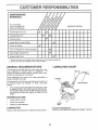
MAINTENANCE
SCHEDULE
FILL IN DATES
AS YOU COMPLETE
REGULAR SERVICE
SERVICE
DATES
Check Engine Oil Level
N,,
Change Engine Oil
Oil Pivot Points
111m,,,
= ,,, ,11,,
Inspect Spark Ar_ester Muffler
JiLuu,=
Inspect Air Screen
Clean or Replace Air Cleaner Cartridge
6/2
Clean Engine Cylinder Fins
6/'
= m,
=,H
Replace Spark Plug
_/
1 - Change more often when operating under a heavy !cad or in high ambient temperatures
2 - Service more often when operating in dirty or dusty conditions
GENERAL
LUBRICATION
RECOMMENDATBONS
CHART
Tile warranty on this tiller does not cover items that have
been subjected to operator abuse or negligence,
To
receive full value from the warranty, operator must maintain tiIter as instructed in this manual
Some adjustments will need to be made periodically
properly maintain your tiller.
to
All adjustments in the Service and Adjustments section of
this manual should be checked at least once each
season..
•
* T|NE CONTROL
Once a year you should replace the spark plug, clean
or replace air filter, and check tines and belt for wear_
A new spark plug and clean air filter assure proper airfuel mixture and help your engine run better and last
IongeL
BEFORE
EACH USE
o
Check engine oil level
*
Check tine operation..
Check for loose fasteners_
* IDLER
ARM
LUBRICATION
Keep unit well lubricated (See "LUBRICATION
J
* SAE 30 OR 10W30 MOTOR OIL
** REFER TO CUSTOMER RESPONSIBILITIES
CHART")
12
"ENGINE"
SECTION_
CUSTO
RESPONS B L
ES
.......................................
,,
i,u
i i
i
.,.,,UUlUllUJ,,i.
,,nl,,,nmll
m .................
Disconnect spark plug wire before performing any maintenance (except carburetor adjustment) to prevent
accidental starting of engine,
Prevent fires! Keep the engine free of grass, leaves, spilled oil, or fueL Remove fuel from tank before tipping
unit for maintenance. Clean muffler area of all grass, dirt, and debris.
Do not touch hot muffler or cylinder fins as contact may cause burns.
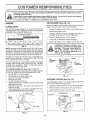
ENGINE
AIR CLEANER
LUBRICATION
Service air cleaner cartridge every twenty-five hours, more
often if engine is used in very dusty conditions,
Use only high quafity detergent oil rated with AP] service
classification SF o r SG Select the oil s SAE viscosity grade
according to your expected temperature
SAE VISCOSITY
GRADES
(See Fig. 13)
o
Loosen air cleaner screws, one on each side of cover
o
Remove air cleaner cover.
•
Carefully remove air cleaner cartridge Be careful Do
not allow dirt or debris to fall into carburetor
o
Ciean by tapping gently on a flat surface
o
If very dirty or damaged, replace cartridge
o
Clean and replace cover. Tighten screws securely
I.....
_F
-20 _
09
°c -doo
30 _
.2'o',
.,o.,
32 _ 40 _
0"
604
'_O
o
80_
2o'
100"
3o"
4o°
TEMPERATURE RANGE ANTIC}PATBD BEFORE NEXT OJLCHANGE
CAUTION: Petroleum
solvents, such
as kerosene, are notto be used to clean
cartridge.
They may cause deterioration of the cartridge.
Do not oil cartridge.
Do not use pressurized air to
clean or dry cartridge.
FIG. 11
NOTE: Althouglq multi-viscosity oils (5W-30, 10W-30, etc.)
improve starting in cold weather, these multi-viscosity oils
will result in increased oil consumption when used above
32°F (0°C). Check your engine oil level more frequently to
avoid possible engine damage from running low on oil
Change the oil after the first two hours of operation and
every 25 hours thereafter or at least once a year if the tiller
is not used for 25 hours in one year.
DOVER
AIR
Check the crankcase oil level before starting the engine
and after each five (5) hours of continuous use.. Add SAE
30 motor oil or equivalent.. Tighten oil filler plug securely
each time you check the oil level,
SCREW
TO CHANGE ENGINE OIL (See Figs. 11 and 12)
Determine temperature range expected before oil change
All oil must meet API service classification SF or SG.
•
Be sure tiller is on level surface.,
o Oil will drain more freely when warm.,
o Catch oil in a suitable container.
.
Remove drain plug,
•
Tip tiller forward to drain oil
o After oil has drained completely, replace oil drain plug
and tighten securely.
o Remove oil filler ptug, Be careful not to allow dirt to
enter the engine
•
Refill engine with oil See "FILL ENGINE WITH OIL"
in the Operation section of this manual.
AIR
CLEANER
CARTRIDGE
FIG. 13
COOLING
SYSTEM
(See Fig. 14)
Your engine is air cooted, For proper engine performance
and long life keep your engine clean.
o
Clean air screen frequently using a stiff-bristled brush
o
Remove blower housing and clean as necessary
•
Keep cylinder fins free of dirt and chaff.
CYLINDER
/
/
FINS
BLOWER
HOUSING
MUFFLER
OIL
DRAIN
PLUG
\
LEVEL
OiL FILLER
PLUG
FIG, t4
FIGo 12
13
MUFFLER
TRANSMISSION
Do not operate tiller without muffler_ Do not tamper with
exhaust system. Damaged mufflers or spark arresters
could create a fire hazard Inspect periodically and replace
if necessary
If your engine is equipped with a spark
arrester screen assembly, remove every 50 hours for
clear_ing and inspection Replace if damaged
Your transmission is sealed and will only require lubrication
if it is serviced°
SPARK
CLEANING
o
=
PLUG
Replace spark plugs at the beginning of each tiIling season
orafterevery50 hoursof use, whichever comes first. Spark
plug type and gap setting is shown in "PRODUCT SPECIFICATIONS" on page 3 of this manual,
,H!
,H
Clean engine, wheels, finish, etc. of all foreign matter
Keep finished surfaces and wheels free of all gasoline,
oil, etc
=
Protect painted surfaces with automotive type wax
We do not recommend using a garden hose to clean your
unit unless the muffler, air filter and carburetor are covered
to keep water out Water in engine can result in a shortened
engine life.
"Hm"HN
= =
Hi
! ' N'NHH
...................................
SERVICE AND ADJUSTMENTS
, into
= U"N,H=
Hi,
'm
==,'HHm
...................................
.....................................
=
1'' ' m' mHHHUH
=
CAUTION: Disconnect spark plug wire from spark plug and place wire where it cannot come into
contact with plug,
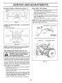
TINE ARRANGEMENT
TOLLER
TO ADJUST
HANDLE
HEIGHT
Yourouter tines can be assembled in several different ways
to suit your tilling or cultivating needs.
(See Fig. 15)
,I
Factory assembly has provided lowest handle height Select handle height best suited for your tilling conditions
Handle height will be different when tiller digs into so{l
o
if a higher handle height is desired, loosen the four nuts
securing handle panel to engine brackets
°
Slide handle panel to desired location
=
Tighten the four nuts securely
NORMAL TILLING - 26 INCH PATH (See Fig. 16)
Assemble holes "A" in tine hubs to holes "B" in tine
shaft.
_.--_"
ENGINE
BRACKETS
A _f
HANDLE
PANEL
CLEVIS
PIN
OUTER
ATIN_
ON LEFT SIDE
OF TILLER)
HAIRPIN CLIP
i
INNER lINE
FIG. 16
NUTS (ALSO 2
FIG. 15
14
SERVICE AND ADJUSTMENTS
FINAL CHECK "ON" POSITION
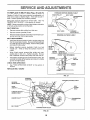
MID-WIDTH TILLING - 24 INCH PATH (See Fig. t7)
•
Assemble holes "A" in tine hubs to holes "C" in line
shaft.
•
With tine control"ON" (held down to handle) push down
on handle to raise tines off the ground,.
•
Slowly pull recoil starter handle while observing tines_
Tines should rotate forward.
•
if tines do not rotate, inner wire of control cable is too
looser Loosen cable clip and pult cable up to remove
slack and retighten clip.
o
Recheck in "ON" position and adjust if necessary..
NOTE; If "ON" position check required adjustment, recheck "OFF" position adjustment to insure tines do not
rotate when control is "OFF" (up),
FIG. 17
NARROW TILLING/CULTIVATING
- 12_3/4 INCH PATH
T1NE CONTROL
"OFF"
POSITION
(See Fig. 18)
o Remove outer tines..
BODY
TINE CONTROL
"ON" POSITION
oo}
CABLE
CLIP
TINE CONTROL
INNER TINES ONLY
FIG, 18
NOTE: When reassembling Outer tines, be sure right tine
assembly (marked "R") and left tine assembly (marked "L")
are mounted to correct side of tine shaft.
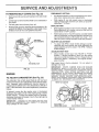
TINE OPERATION
CHECK
(See Fig, 19)
i
i&
ilnl,
i
i,nlll,n,lll
from spark plug to prevent starting
WARNING:
Disconnectsparkplugwire
while checking
tine operation.
!
For proper tine operation, forward tine control lever must be
against control body and all slack removed from inner wire
of control cable when control is in the "OFF" (up) position°
FIG_ 19
If lever and cable are loose, loosen cable clip at lower end
of cable,. PuN up on cable to remove slack, without
extending spring on end of cable, and retighten cable clip.
FINAL CHECK "OFF" POSITION
•
With tine control "OFF" (up), push down on handle to
raise tines off the ground
•
Slowly pull recoil starter handle while observing tines,
Tines should not rotate
o
If tines rotate, inner wire of control cable is too tight
which is extending lower spring and engaging tines
Loosen cable clip and push down on cable only enough
to relieve spring tension, Tighten cable clip,
-
Recheck in "OFF" position and adjust if necessary_
15
CABLE
TO REPLACE
V-BELTS
FORWARD MOTION (INSIDE) V-BELT
(See Figs. 20 and 21)
ENGINE PULLEY
Replace V-belts if they have stretched considerably or if
they show cracks or frayed edge& There are two (2) Vbelts - forward (inside) and reverse (outside),
/
BELT GUIDE
_
TRANSMISSION
PULt.EY
Belt guard must be removed to service belt& See "TO
REMOVE BELT GUARD" in this section of manual
NOTE: Observe carefully routing of both belts and location
of al belt guides before removing bets
REVERSE
IDLER PULLEY
BELT REMOVAL
o
Remove reverse idler pulley from idler arm,.
o
Remove reverse (outside) V-bett,.
BELT GUIDE
o
Remove forward (inside) V-belt from transmission pulley first and then from engine puley
BELT REPLACEMENT
.
Install new forward (inside) V-belt to engine pul]ey first
then to transmission pulley,, Be sure belt is positioned
on inside groove of both pulleys, inside all belt guides
and rests on idler pulley,.
°
Before insta!lng reverse (outside) V-belt, turn bett
"inside out'L Twist so wide, flat surface of belt is to
inside.
°
Wrap V-bel around reverse idler pulley and reassemble idler to idler arm,. Tighten securely. Be sure
belt is between reverse idler pulley and idler arm pin,,
-
FORWARD
IDLER PULLEY
REVERSE (OUTSIDE) V-BELT
/
FRONT VIEW REFERENCE
Instal belt to outside groove of transmission puley,. Be
sure belt is inside all belt guides and rests on outside
groove of engine pulley,.
REVERSE
_
IDLER PULLEY
__
- IDLER
_._""
ARM PIN
CHECK TINE OPERATION
.
See "TINE OPERATION
manual
CHECK" in this section of
REPLACE BELT GUARD
FtG. 21
REVERSE
IDLER ARM
REVERSE (OUTSIDE,
REVERSE
IDLER PULLEY
V-BELT
/
BELT
lARD
BOLT
IDLER
ARM PIN
FORWARD
(INSIDE) V-BELT
ENGINE PULLEY
[RANSMISSION
PULLEY
BELT GUIDE'
FORWARD IDLER PULLEY
FIG. 20
16
SERVICE AN
TO REMOVE
BELT
GUARD
ADJUSTME , TS
PRELIMINARY SETTING
(See Fig. 22)
o
Remove two (2) cap nuts and washers from side of belt
guard.
o
o
Loosen (do not remove) fine shield nut on underside of
tine shield..
o
o
Pull belt guard out and away from unit.
-
Replace belt guard by reversing above procedure. Be
sure slot in bottom of belt guard is under head of tine
shield bolt and all nuts are tightened securely.
o
Start engine and allow to warm for five minutes Make
final adjustments with engine running at idle and line
control lever in "OFF" position
o
With throttle contro! in "SLOW" position, turn idle needle
valve in (clockwise) until engine begins to die then turn
out (counterclockwise) until engine runs rough_ Turn
valve to a point midway between those two positions
IDLE RPM ADJUSTMENT
o
To adjust idle RPM, rotate throttle linkage counterclockwise and hold against stop while adjusting idle
speed adjusting screw to obtain 1750 RPM Release
throttle linkage
ACCELERATION TEST
o Move throttle control lever from "SLOW" to "FAST"
position. If engine hesitates or dies, turn idle needle
valve out (counterclockwise) 1iSturn. Repeattestand
continue to adjust, if necessary, until engine accelerates smoothly
BELT
GUARD
High speed stop is factory adjusted
Do not adjust or
damage may result.
IMPORTANT:
NEVER TAMPER WITH THE ENGINE
GOVERNOR, WHICH IS FACTORY SET FOR PROPER
ENGINE SPEED OVERSPEEDtNG THE ENGINE ABOVE
THE FACTORY
HIGH SPEED SETTING
CAN BE
DANGEROUS IF YOU THINK THEENGINE-GOVERNED
HIGH SPEED NEEDS ADJUSTING, CONTACT YOUR
NEAREST SEARS SERVICE CENTER/DEPARTMENT,
WHICH HAS PROPER EQUIPMENT AND EXPERIENCE
TO MAKE ANY NECESSARY ADJUSTMENTS
TINE SHIELD NUT
FIG. 22
ENGINE
CARBURETOR
With engine off, turn idle needle valve in (clockwise)
closing it finger tight and then turn valve out (counterclockwise) 1-1/2 turns
FINAL SETTING
CAP N UTS
WASHERS
TO ADJUST
Air cleaner assembly must be assembled to the carburetor when making carburetor adjustments.
(See Fig. 23)
The carburetor has a high speed fixed jet and has been
preset at the factory and adjustment should not be necessary. However, minor adjustments may be required to
compensate for differences in fuel, temperature, altitude or
load. If the carburetor does need adjustment, proceed as
follows.
THROTTLE
LINKAGE
THROTTLE
STOP
In general, turning the idle needle valve in (clockwise)
decreases the supply of fuel to the engine giving a leaner
fuel/air mixture. Turning the needle valve out (counterclockwise) increases the supply of fuel to the engine giving
a richer fue!/air mixture..
IMPORTANT:
DAMAGE TO THE NEEDLES AND THE
SEATS IN CARBURETOR MAY RESULT IF SCREWS
ARE TURNED fN TOO TIGHT
IDLE SPEED
ADJUSTING SCREW
IDLE NEEDLE VALVE
FIGo23
17
STORAGE
ENGINE
immediately prepare your tiller for storage at the end of the
season or if the unit will not be used for 30 days or more
Drain oil (with engine warm) and replace with clean oil,
(See"ENG INE" in the Customer' Responsibilities section of
this manual).
' i1,1 ,i,1,,11,11,,, ,i, i ill
gasoline in the tank inside a building
where fumes may reach an open flame
or spark.
Allow the engine to cool
AUTION: Never store the tiller with
before storing in any enclosure.
I_
OIL
CYLINDERS
o
Remove spark plug..
-
Pour 1 ounce (29 ml) of oil through spark plug hole into
cylinder°
TILLER
•
Pull starter' handle slowly several times to distribute oil
o
Clean entire tiller (See "CLEANING" in the Customer
Responsibilities section of this manual).
o
Replace with new spark plugo
,
Inspect and replace belts, if necessary (See belt replacement instructions in the Service and Adjustments
section of this manual).
OTHER
o
Do not store gasoline
,
Lubricate as shown in the Customer Responsibilities
section of this manual
o
Replace your gasoline can if your can starts to rust.
Rust and/or dirt in your gasoline will cause problemso
-
Be sure that all nuts, bolts and screws are securely
fastened. Inspect moving parts for damage, breakage
and wear. Replace if necessary
o
If possible, store your unit indoors and cover' it to give
protection from dust and dirt.
°
Touch up all rusted or chipped paint surfaces; sand
lightly before painting
i
,i
i,
iii
ii!lll
o
Cover your unit with a suitable protective cover that
does not retain moisture. Do not use plastic. Plastic
cannot breathe which allows condensation to form and
will cause your unit to r'usL
IMPORTANT:
NEVER COVER TILLER WHILE ENGINE
AND EXHAUST AREAS ARE STILL WARM.
ENGINE
FUEL sYSTEM
IMPORTANT:
IT IS iMPORTANT TO PREVENT GUM
DEPOSITS FROM FORMING IN ESSENTIAL FUEL
SYSTEM PARTS SUCH AS THE CARBURETOR, FUEL
FILTER, FUEL HOSE, OR TANK DURING STORAGE
ALSO, EXPERIENCE
INDICATES THAT ALCOHOL
BLENDED FUELS (CALLED GASOHOL OR USING
ETHANOL OR METHANOL) CAN ATTRACT MOISTURE
WHICH LEADS TO SEPARATION AND FORMATION OF
ACIDS DURING STORAGE. ACIDIC GAS CAN DAMAGE
THE FUEL SYSTEM OF AN ENGINE WHILE IN STORAGE.
°
Drain the fuel tank.
o
Start the engine and let it run until the fuel lines and
carburetor are empty
•
Never use engine or carburetor cleaner products in the
fuel tank or permanent damage may occur..
°
Use fresh fuel next season°
from one season to another.
NOTE: Fuel stabilizer is an acceptable alternative in
minimizing the formation of fuel gum deposits during storage. Add stabilizer' to gasoline in fuel tank or storage
container_ Always follow the mix ratio found on stabilizer'
container. Run engine at least 10 minutes after adding
stabilizertoallowthestabilizerto
reach the carburetor. Do
not drain the gas tank and carburetor if using fuel stabilizer.
18
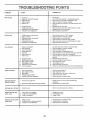
TROU
LESHOOT NG
..................
PROBLEM
H
i,
POBNTS
ill
................
CAUSE
CORRECTION
i
Will not start
1
Fill fuel tank
2
3
4
5
See qO START ENGINE" in the Operation section
Wait several minutes belore affempting to start
C{ean or replace air cleaner cartridge
Drain fuel tank and carburetor, and refill tank with fresh
Clogged fuel tank
Loose spark plug wire
Bad spark plug or improper gap
Carburetor out of adjustment
6.
gasoline
Remove fuel tank and clean
7
8
9
Make sure spark plug wire is seated properly on plug
Replace spark plug or adjust gap
Make necessary adjustments
1
2
3
4
5
6
Throttle control not set properly
Dirtyair cleaner
Bad spark plug or improper gap,
Stale ordirty fuel
Loose spark plug wire
Carburetor out of adjustment
t
2
3.
4
5
6
Place throttle control in "FAST" position
Clean or replace air cleaner cartridge
Replace spark plug or adjust gap
Drain fuef tank and refill with fresh gasoline
Make sure spark plug wire is seated properly on plug
Make necessary ad}ustments
1
2
3
4
5
6.
7
Engineis overloaded
Dirty air c{eaner
Low oil level!dirty oi{
Faulty spark p_ug
Oil in rue{
Stale ordirty fuel
Waterin fuel
1
2
3
4
5
6
7
Clogged fuel tank
Spark plug wire loose
Dilly engine air screen
Dirty/clogged muffler
Carburetor out of adjustment
Poor compression
8
Set depth stake and wheels for shallower filling
Clean or replace air cleaner cartridge
Check oil feveVchange oit
Clean and regap or change spark plug
Drain and clean luel tank and refill, and dean carburetor
Drain fuel tank and relief with fresh gasoline
Drain fuel tank and carburetor, and refill tank with fresh
gasoline
Remove fuel tank and clean
9
10
11
12
13
Connect and tighten spark plug wire
Clean engine air screen
Clean/replace muffler
Make necessary adjustments
Contact an authorized Sears Service Center/Department
1
Out of fuel
2
3
4
5
Engine not "CHOKED"
Engine flooded
Dirtyair cleaner
Water in fuel
6
7
8
g
Hard to start
Loss of power
8
9
t0
t 1
12
13
Engine
overheats
properly
1
2
3
4
5
Low oil level/dirty oit
Dirty engine air screen
Dirty engine
Partially plugged muffler
Improper carburetor adjustment
1
2
3
4
5
Check oil level/change oil
Clean engine air screen
Clean cylinder fins, air screen, muffler area
Remove and clean muffler
Adjust carburetor to richer position
1
Ground too dry and hard
I
2
Wheels and depth stake incorrectly adjusted
2
Moisten ground or wait for more favorable soil
condiliens
Adjust wheels and depth stake
1
Ground too wet
1
Wait for more favorable
1
2
3
Tine control is not engaged
V-belt not correctly adjusted
V-beltis off pulley(s)
2
3
Engage line control
Inspect/adjust V-belt
Inspect V-belt
!
2
3
Tilling too deep.
Throttle control not properly adjusted
Carburetor out of adjustment
1,
2
3
Set depth stake for shallower tilling
Check throltte control setting
Make necessary adjustments
LUlL
Excessive bounce/
difficult handling
Soil balls up or clumps
soil conditions
i innlnlll
Engine runs but tiller
won't move
n l 11111111
Engine runs but
when tilling
labors
19
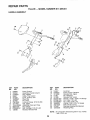
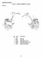
RE!PAURPARTS
TILLER - - MODEL NUMBER
HANDLE
917.295451
ASSEMBLY
22
17
18
\
19
/
12
KEY
NO.
PART
NO.
2
3
4
5
6
7
8
9
10
11
12
13
14
136993
152094
110632X
3066J
151229
12000027
151463
73970500
121!45X
110514X500
98000129
STD533107
136998
DESCRIPTION
KEY
NO.
15
16
17
18
19
2O
21
22
23
24
25
26
Panel, Control
Assembly, Handle Column
Grip, Handle
Cable, Tine Control
Lever, Control, Tine
Ring, Clp
Pin, Pivot
Locknut, Flange 5/16-18 UNC
Clip, Cable
Assembly, Panel and Tube
Nut, Flange
Bolt, Carriage 5/16-18 x 3/4
Bracket; Reverse Rod
PART
NO.
139907
106932X
101248K
1778E
137056
STD551037
STD561210
STD560907
19090814
72010520
137640
12000059
NOTE:
2O
DESCRIPTION
G rommet
Knob, Control, Reverse
Reverse Rod, Upper
Pin, Retaining
Reverse Rod, Lower
Washer 13/32 x 13/16 x 16 Gauge
Pin, Cotter 1/8 x 3/4
Pin, Cotter 3/32 x 1/2
Washer 9/32 x 1/2 x 14 Gauge
Bolt 5/16-18 x 2-!/2
Bushing, Reverse Rod Bracket
Retaining Ring
All component dimensions given in U,S, inches,
1 inch = 2&4 mm
REPAIR PARTS
TSLLER - - MODEL
BELT GUARD
AND PULLEY
NUMBER
917.295451
ASSEMBLY
\\
29
s
10
7
11
12
16
18
KEY
NO.
1
2
3
4
5
6
7
8
9
10
11
12
13
14
15
16
17
PART
NO.
123643X
9484R
86777
74770812
STD541037
19131316
2009J
127180X
74760628
106970X459
STD551025
104213X
72140405
133035
26t4J
12000028
2649M
DESCRIPTION
Assembly, Bracket, Belt Guard
Clip, Cable
Screw, Hex Washer Head, Slotted,
Thread Cutting #10-24 x 1/2 Type D
Bolt, Hex Head 1/2-20 x 3/4
Nut, Hex 3/8-16
Washer 13/32 x 13/16 x 16 Gauge
Pulley, Idler, Reverse
Assembly, Arm, Reverse Idler
Bolt, Hex Head 3/8-16 x 1-3/4
Guard, Belt
Washer 9/32 x 5/8 x 16 Gauge
Nut, Cap 1/4- 20
Bolt, Carriage 1/4-20 x 5/8
V-Belt (Forward Motion)
V-Belt (Reverse)
Ring, Retainer
Key, Square
KEY
NO,
PART
NO,
!8
19
20
21
22
23
24
25
26
27
28
29
30
151236
1t0550X
12000036
STD541237
9178R
674A30
STD523712
106968X
73350500
STD541025
STD551125
109227X
23200404
31
32
101189L
151223
NOTE:
21
DESCRIPTION
Sheave, Transmission Fiat
Bolt, BeltGuard
Ring, Klip
Nut, Hex, Jam 3/8-16
Pulley, Idler
Arm, Idler
Bolt, Hex Head 3/8-16 x 1-1/4
Shaft, IdlerArm
Nut, Hex, Jam 5/16-18
Nut, Hex 1/4-20
Washer, Lock 1/4
Pad, Idler
Screw, Set, Socket, Headless
C.P. 1/4-20 x t/4
Sheave, Engine
Sheave, Transmission "D"
All component dimensions
1 inch = 25,4 mm
given in tJ,So inches,
REPAIR PARTS
TILLER
WHEEL AND DEPTH
17
STAKE
19
- - MODEL NUMBER
917.295451
ASSEMBLY
F
20
2O
18
16
17
KEY
NO.
PART
NO.
1
2
3
4
5
6
7
8
9
10
11
9194R
7476O520
STD523107
STD541031
STD551131
73800600
4921H
1952J
122233X
326J
74780628
DESCRIPTION
Pin, Clevis
Bolt, Hex Head 5/16-18 x t-1/4
Bolt, Hex Head 5/16-18 x 3/4
Nut, Hex 5/16-!8
Washer, Lock 5/16
Locknut, w/washer 3/8-t6
Clip, Hairpin
Support, Depth Stake, R_H
Stake, Depth
Pin, Clevis
Bolt, Fin, Hex 3/8-16 x 1-3/4
KEY
NO.
PART
NO.
12
13
14
15
16
17
18
19
20
21
22
74760524
1951J
120958X
5388J
12!117X
9188R
STD551037
9190R
STD541437
74760516
73800500
NOTE:
22
DESCRIPTION
Bolt, Hex 5/16-18 x 1-1/2 Grade 2
Support, Depth Stake, L.H.
Washer
Spring, Stake
Bolt, Shoulder
Wheel
Washer 13/32 x 13116 x !1 Gauge
Bracket, Wheel
Locknut, Crown 3/8-16
Bolt, Hex Head 5/16-18 x 1
Locknut, w/insert 5116-18
All component dimensions given in U.So inches,
1 inch = 25°4 mm
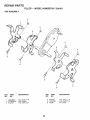
REPAIR PARTS
TSLLER - - MODEL
NUMBER
917.295451
TINE ASSEMBLY
2
1
2
2
i
9"
/
2
6
I
6
KEY
NO.
PART
NO.
1
2
3
100746M
STD624008
674A43
KEY
NO.
DESCRIPTION
4
5
6
Tine, Outer, R.H
Clip, Hairpin
Tine, Inner, R.H.
23
PART
NO.
674A42
100744M
4929H
DESCRIPTION
Tine, Inner, L.H.
Tine, Outer, L.H.
Pin, Clevis
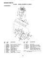
REPAIR PARTS
TroLLER - - MODEL
TRANSMISSION
NUMBER
917.295451
... .... ...
20
2
3
KEY
NO.
PART
NO.
1
2
3
5
6
7
8
9
10
11
12
13
74760524
7478O652
STD551037
73800600
9057R459
t949J
110519X
STD551131
STD541031
74760544
151222
19171616
DESCRIPTION
KEY
PART
NO.
NO.
14
15
16
17
18
19
2O
Bolt, Hex 5t16-18 x 1-1/2 Grade 2
Bolt, Fin, Hex 3/8-16 x 3-!/4
Washer' 13/32 x 13/16 x 11
Locknut, w/washer 3/8-16
Shield, Tine
Bracket, Engine, RrH
Bracket, Engine, L.H.
Washer, Lock 5/16
Nut, Hex 5/16-18
Bolt, Hex Head 5/16-18 x 2-3/4
Transmission
Washer 17/32 x 1 x 16 Gauge
9173R
STD541431
19O91412
19092016
STD551125
7461O412
146151
NOTE:
24
DESCRIPTION
Spacer, Split
Nut, Hex, Keps 5/16-18 UNC
Washer 9/32 x 7/8 x 12 Gauge
Washer 9/32 x 1-1/4 x 16 Gauge
Washer, Lock 1/4
Bolt, Hex 1/4-28 x 3/4 Grade 5
Engine,
Briggs
& Stratton, 5 HP,
Model Nov 133202, Type 0156-01
All component dimensions
1 inch = 2&4 rnm
given in U_S..inches.
RE!PARRPARTS
TILLER -- MODEL
NUMBER
917.295451
DECALS
2
KEY
NO.
1
2
3
4
5
6
8
PART
NO.
152348
152344
152350
137653
120431X
110719X
120075X
153196
153197
DESCR1P3"ION
Decal, Logo
Decal, Logo
Decal, Logo
Decal, Caution, Tine Control
Decal, Hand Placement
Decal, Operation and Lubrication
Decal, Warning, Rotating Tines
Manual, Owner's(English)
Manual, Owner's(Spanish)
25
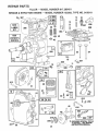
REPAnR PARTS
TILLER - - MODEL
BRiGGS & STRATTON
NUMBER
917.295451
ENGINE - - MODEL NUMBER
133202, TYPE NO. 0156-01
14
3O8
LABEL
1019
KIT
1058
OWNER'S
MANUAL
7
3
34
15
613
26
81
978
12
45
,o&&
616
//
"A"REQUIRES SPECIAL TOOLS
TO INSTALL. SEE REPAIR
INSTRUCTION MANUAL.
26
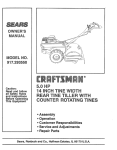
REPAIR PARTS
TILLER
- - MODEL
NUMBER
467
191
209
181
526
27
917.29545!
968
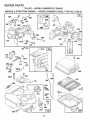
REPAIR PARTS
TILLER
BRIGGS & STRATTON
- - MODEL
NUMBER
ENGINE - - MODEL NUMBER
"A"REQUIRES SPECIAL TOOLS
TO INSTALL. SEE REPAIR
INSTRUCTION MANUAL,
334
917.295451
133202, TYPE NO. 0156-01
23
200
37
978
12
52
307
7
332
455
121 CARBURETOR
305
OVERHAUL
KIT
163
191
52
163
1016
461
69A
515
58
456
28
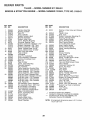
REPAaR PARTS
TILLER - - MODEL
BRIGGS
KEY PART
NO. NO.
1
2
3
5
7
8
9
10
11
12
13
14
15
16
18
19
20
2t
22
23
24
25
26
27
28
29
30
32
33
34
35
36
37
395990
297565
299819
214040
272157
495774
27549
94621
66578
270080
270125
270126
94221
94679
93448
94387
492088
230978
2976O2
495660
294606
66768
94682
297229
222698
298904
298905
298906
298907
298982
299742
298983
298984
298985
26026
2989O9
298908
299430
390459
221890
94745
211119
261044
260552
26478
222443
& STRATTON
ENGINE
NUMBER 9'17.295451
- - MODEL
NUMBER
133202,
KEY PART
NO. NO.
DESCRIPTION
Cylinder Assembly
Bushing, Cylinder
Seaf, Oil
Head, Cylinder
Gasket, Cylinder Head
Breather Assembly
Gasket, Valve Cover
Screw, Breather Mounting
G[ommet, Breather Tube
Gasket, Crankcase, Standard .015"
Gasket, Crankcase °005" Thick
Gasket, Crankcase 009" Thick
Screw, Cylinder Head 2-3/32"
Screw, Cylinder Head 2-15/32"
Plug, Pipe, Hex Socket
Plug, Oil Drain
Crankshaft
Gear Pin, Crankshaft
Cover Assembly, Crankcase
Bushing, Crankcase Cover
Seal, Oit
Plug, Oil Filler
Screw, Cover Mounting
Flywheel, Magneto
Key, Flywheel
Piston Assembly, Standard Size
Piston Assembly ..010" Oversize
Piston Assembly ..020" Oversize
Piston Assembly .030" Oversize
Ring Set, Piston, Standard Size
Ring Set, Piston, Standard, Chrome
Ring Set, Piston .010" Oversize
Ring Set, Piston 020" Oversize
Ring Set, Piston 030" Oversize
Lock, Piston Pin
Pin Assembly, Piston, Standard
Pin Assembly, Piston 005" Over
Rod Assembly, Connecting
Rod Assembly, Connecting
.020" Undersize Crankpin Bore
Dipper, Connecting Rod
Screw, Connecting Rod
Valve, Exhaust
Valve, Intake
Spring, Intake Valve
Spring, Exhaust Valve
Guard, Flywheel
40
93312
45
46
52
55
56
57
58
260642
212733
271936
494846
493824
262594
280406
59 396892
60 393l 52
65 94686
69 280973
69A 224322
73 224632
81 222263
90 495426
95 93499
96 223793
97 490048
108 491177
!18 231533
121 495606
124 94616
127 220352
t27A 223789
149 26336
152 260575
153 490589
154 93527
163 271935
!80 495405
181 494559
190 94712
190A 94677
191 272489
200 223886
202 262270
203 280720
*
**
***
Included in
included in
Included in
Carburetor
TYPE
NO. 0156-01
DESCRIPTION
Retainer, intake Valve and Exhaust
Spring
Tappet, Valve
Gear, Cam
*** Gasket, Carburetor Mounting (2)
Housing, Rewind Starter
Pulley, Rewind Starter
Spring, Rewind Starter
Rope, Rewind Starter
(Cut to Required Length)
Insert, Starter Handle
Handle, Rewind Starter
Screw, Housing Mounting
Washer
Washer
Screen, Rotating
Lock, Screw
Carburetor Assembly
Screw, Throttle Valve to Shaft
Throttle, Carburetor
Shaft and Lever, Throttle
Valve and Shaft Group, Choke
Valve, Needle
Carburetor Overhaul Kit
Screw, Hex Head
Plug, Welch
Plug, Welch
Spring, Needle Valve
Spring, Throttle Adjustment
Screw and Collar
Screw, Machine, Round Head
* Gasket, Air Cleaner Mounting
Tank Assemb]y, Fuel
Cap, Fuel Tank
Screw, Fuel Tank
Screw, Fuel Tank Mounting 1-3/4"
*** Gasket, Fuel Tank to Carburetor
Guide, Air
Link, Throttle
Bell Crank
Gasket Set (495603)
Carburetor Overhaul Kit (495606)
both Gasket Set (495603), and
Overhaul Kit (495606)
NOTE: All component dimensions given in U.S inches
1 inch = 25,4 mm
29
REPAUR PARTS
TILLER
BRmGGS & STRATTON
KEY PART
NO. NO.
204
205
208
209
216
219
220
222
223
224
222962
231520
262279
262283
262359
494845
221551
490649
223455
93491
227
230
256
257
300
304
305
306
307
308
332
333
334
337
346
356
358
363
373
383
392
394
4t4
432
433
434
435
455
456
459
461
467
515
526
527
490374
222450
223813
93543
393615
495759
94619
22151t
94680
224738
92284
397358
93414
802592
93705
398808
495603
19069
92987
89838
262328
272538
220982
221377
93265
214021
93141
224250
224321
492833
262626
280715
262625
94659
223786
-- MODEL
NUMBER
917.295451
ENGINE - - MODEL NUMBER
133202, TYPE NO. 0156-01
KEY PART
NO. NO.
DESCRIPTION
Bushing, Governor Lever, Flat
Screw, Shoulder
Rod, Speed Control
Spring, Governor
Link, Choke
Gear, Governor
Washer, Thrust
Panel, Control
Lever, Governor Control
Rivet, Governor Control Lever
Mounting
Lever Assembly, Governor
Washer, Governor Lever
Crank, Belt
Screw, Sems, Hex Head
Muffle[, Exhaust
Housing, Blower
Screw, Blower Housing Mounting
Shield, Cylinder
Screw, Cylinder Shield
Cover, Cylinder Head
Nut, Flywheel
Armature Group
Screw, Armature Mounting
Plug, Spark
Screw, Seres
Wire, Ground
Gasket Set
Flywheet Puller
Nut, Hex
Wrench, Spark Plug
Spring, Fuel Pump Diaphragm
**Diaphragm
Washer
Cap, Spring
Pin, Diaphragm Cover
Cover, Diaphragm
Screw, Diaphragm Cover
Cup, Starter'
Retainer
Pawl, Starter
Pin, Spring
Knob, Control
Spring
Screw, Seres, Tank Bracket MounL
Clamp, Breather Tube
528
529
542
552
562
592
608
611
613
614
615
616
621
634
635
676
679
680
741
779
851
869
870
871
916
966
967
968
969
971
987
995
1012
1016
231550
67838
93572
231079
92613
231082
495766
391813
93935
93306
93307
231077
396847
271853
66538
393757
270382
221839
261696
262570
221798
21 !787
211172
262001
63709
280321
492797
491588
495357
490073
94018
398970
223887
490507
224278
RPM Settings:
*
**
***
Included in
Included in
included in
Carburetor'
DESCRIPTION
Tube, Breather
Grommet, Breather' Tube
Screw
Bushing, Governor Crank
Bolt, Governor Lever
Nut, Hex
Starter Assembly, Rewind
Fuel Pipe and Clip Asse51bly
Screw, Hex Head, Shoulder
Pin, Cotter
Retainer, E-Ring
Crank, Governor
Switch, Stop
Washer', Throttle Shaft, Foam
Elbow, Spark Plug
Deflector, Exhaust, Side Outlet
Washer, Foam
Washer, Brass
Gear, Timing
Link, Speed Control
Cable Terminal, Ignition
Seat, Intake Valve, Standard
Seat, Exhaust Valve, Standard
Guide, Exhaust Valve
Guide, Intake Valve
Rack, Gear Control
Base, Air Cleaner
Filter, Air Cleaner
Cover, Air Cleaner
Screw, Air Cleaner
Screw, Hex Head
Seal, Throttle Shaft
Lever, Bracket Assembly
Retainer, Link
Spacer
Low Speed: 1750-1950
High Speed: 3400-3600
Gasket Set (495603)
Carburetor Overhaul Kit (495606)
both Gasket Set (495603), and
Overhaul Kit (495606)
NOTE: Al! component dimensions given in U.S. inches
1 inch = 25.4 mm
3O
SERVICE NOTES
i
i
..... i,,,,,i,,,r,r,r
31
®
Each tilter has its own model number.
number..
Each engine has its own model
The model number for your tiller will be found on a plate attached to the
right hand engine bracket..
The model number for your engine will be found on the btower housing of
the engine.
At] parts listed herein may be ordered from any Sears, Roebuck and Co.
Service Center?Department and most Retail Stores.
iF YOU NEED
REPAIR SERVICE
OR PARTS:
WHEN ORDERING REPAIR PARTS, ALWAYS
ING INFORMATION:
FOR REPAIR SERVICE, CALL
THIS TOLL FREE NUMBER:
,, PRODUCT - FRONT TINE TILLER
• MODEL NUMBER - 917.295451
1-800-4-REPAIR
a ENGINE MODEL NUMBER - 133202, TYPE NUMBER 0156-,01
(1-800-473-7247)
o PART NUMBER
= PART DESCRIPTION
FOR REPLACEMENT PARTS
INFORMATION AND
ORDERING, CALL THIS
TOLL FREE NUMBER:
Your Sears merchandise has added value when you consider Sears has
service units nationwide staffed with Sears trained technicians.,, professional technicians specifically trained to insure that we meet our pledge
to you, we service what we sell.
1-800-FON-PART
(1-800-366-7278)
............
iii i ii ,i,,i
i, iiiiiiii
I
GIVE THE FOLLOW-
IIIIIll
iil-ii,
IIIMIIIII'I
II1" ,111,111,
Sears, Roebuck
and Co., Hoffman Estates, IL 60179 U.S.A.
i! ii iiill
153196
Rev. t
1.25o96 TR
PRINTED tN THE U_S_Ao