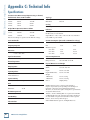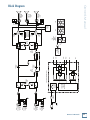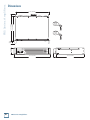
1
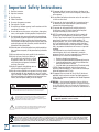
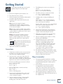
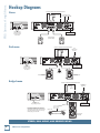
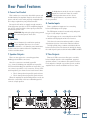
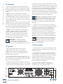
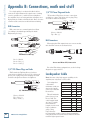
FRS Series
Two Channel Power Amplifiers
FRS•1700 and FRS•2800
OWNER’S MANUAL
FRS•2800
FAST RECOVERY POWER AMPLIFIER
1
2
OL
OL
-3
-3
-6
-6
-9
OO
MAX
-9
-20
-20
SIG
SIG
OO
MAX
INPUT
FRS•2800
FAST RECOVERY POWER AMPLIFIER
CHANNEL 2
CHANNEL 1
BRIDGED
FILTER
SUBSONIC @ 30Hz
POWER CONSUMPTION
2000 W
THIS DEVICE COMPLIES WITH PART 15 OF THE FCC RULES. OPERATION IS SUBJECT TO THE
FOLLOWING TWO CONDITIONS: (1) THIS DEVICE MAY NOT CAUSE HARMFUL INTERFERENCE,
AND (2) THIS DEVICE MUST ACCEPT ANY INTERFERENCE RECEIVED, INCLUDING INTERFERENCE
THAT MAY CAUSE UNDESIRED OPERATION.
CLIP LIMIT
SPEAKER OUTPUTS
Use only class 3 wiring
PIN
CH 2 1+
1
BRIDGED
PIN
1+
2+
CH 1
PIN
1+
1
AMP MODE
AVIS: RISQUE DE CHOC ELECTRIQUE — NE PAS OUVRIR
WARNING: TO REDUCE THE RISK OF FIRE OR ELECTRIC
SHOCK, DO NOT EXPOSE THIS EQUIPMENT TO RAIN OR
MOISTURE. DO NOT REMOVE COVER. NO USER SERVICEABLE
PARTS INSIDE. REFER SERVICING TO QUALIFIED PERSONNEL.
AVIS: N'OUVREZ PAS LA COUVERTURE. N'EXPOSEZ PAS
CET ÉQUIPEMENT À LA PLUIE OU À L'HUMIDITÉ.
MONO STEREO BRIDGE
CH 2
PIN
2+ 1+
2 1
CH 1
THRU
THRU
FRS Series Amplifiers
Important Safety Instructions
15.This apparatus shall not be exposed to dripping or splashing, and no
object filled with liquids, such as vases or beer glasses, shall be placed
on the apparatus.
1. Read these instructions. 2. Keep these instructions.
3. Heed all warnings.
16.Do not overload wall outlets and extension cords as this can result in a
risk of fire or electric shock.
4. Follow all instructions.
5. Do not use this apparatus near water.
6. Clean only with a dry cloth.
7. Do not block any ventilation openings. Install in accordance with the
manufacturer’s instructions.
8. Do not install near any heat sources such as radiators, heat registers,
stoves, or other apparatus (including amplifiers) that produce heat.
9. Do not defeat the safety purpose of the polarized or grounding-type
plug. A polarized plug has two blades with one wider than the other.
A grounding-type plug has two blades and a third grounding prong.
The wide blade or the third prong are provided for your safety. If the
provided plug does not fit into your outlet, consult an electrician for
replacement of the obsolete outlet.
10.Protect the power cord from being walked on or pinched particularly at
plugs, convenience receptacles, and the point where they exit from the
apparatus.
11.Only use attachments/accessories specified by the manufacturer.
12.Use only with a cart, stand, tripod, bracket, or
table specified by the manufacturer, or sold with
the apparatus. When a cart is used, use caution
when moving the cart/apparatus combination to
avoid injury from tip-over.
PORTABLE CART
WARNING
13.Unplug this apparatus during lightning storms or
when unused for long periods of time.
14.Refer all servicing to qualified service personnel. Servicing is required
when the apparatus has been damaged in any way, such as powersupply cord or plug is damaged, liquid has been spilled or objects have
fallen into the apparatus, the apparatus has been exposed to rain or
moisture, does not operate normally, or has been dropped.
CAUTION
RISK OF ELECTRIC SHOCK. DO NOT OPEN
CAUTION: TO REDUCE THE RISK OF ELECTRIC SHOCK DO NOT REMOVE COVER (OR BACK)
NO USER-SERVICEABLE PARTS INSIDE. REFER SERVICING TO QUALIFIED PERSONNEL
The lightning flash with arrowhead symbol within an equilateral triangle is
intended to alert the user to the presence of uninsulated "dangerous
voltage" within the product's enclosure, that may be of sufficient magnitude
to constitute a risk of electric shock to persons.
17.This apparatus has been designed with Class-I construction and must
be connected to a mains socket outlet with a protective earthing connection (the third grounding prong).
18.This apparatus has been equipped with an all-pole, rocker-style AC mains power switch. This switch is located on the front panel and should remain readily accessible to the user.
19.NOTE: This equipment has been tested and found to comply with
the limits for a Class B digital device, pursuant to part 15 of the FCC Rules. These limits are designed to provide reasonable protection
against harmful interference in a residential installation. This
equipment generates, uses, and can radiate radio frequency energy
and, if not installed and used in accordance with the instructions,
may cause harmful interference to radio communications. However,
there is no guarantee that interference will not occur in a particular
installation.
If this equipment does cause harmful interference to radio or
television reception, which can be determined by turning the
equipment off and on, the user is encouraged to try to correct the
interference by one or more of the following measures:
• Reorient or relocate the receiving antenna.
• Increase the separation between the equipment and the receiver.
• Connect the equipment into an outlet on a circuit different from
that to which the receiver is connected.
• Consult the dealer or an experienced radio/TV technician for help.
CAUTION: Changes or modifications to this device not expressly
approved by LOUD Technologies Inc. could void the user's authority to
operate the equipment under FCC rules.
20.This apparatus does not exceed the Class A/Class B (whichever is
applicable) limits for radio noise emissions from digital apparatus as
set out in the radio interference regulations of the Canadian Department
of Communications.
ATTENTION — Le présent appareil numérique n’émet pas de bruits radioélectriques dépassant las limites applicables aux appareils numériques
de class A/de class B (selon le cas) prescrites dans le réglement sur le
brouillage radioélectrique édicté par les ministere des communications du
Canada.
WARNING — To reduce the risk of fire or electric shock, do not
expose this apparatus to rain or moisture.
The exclamation point within an equilateral triangle is intended to alert the
user of the presence of important operating and maintenance (servicing)
instructions in the literature accompanying the appliance.
Correct Disposal of this product: This symbol indicates that this product should not be disposed of with your household waste, according to the WEEE Directive
(2002/96/EC) and your national law. This product should be handed over to an authorized collection site for recycling waste electrical and electronic equipment (EEE). Improper handling
of this type of waste could have a possible negative impact on the environment and human health due to potentially hazardous substances that are generally associated with EEE. At the
same time, your cooperation in the correct disposal of this product will contribute to the effective usage of natural resources. For more information about where you can drop off your waste
equipment for recycling, please contact your local city office, waste authority, or your household waste disposal service.
2
FRS Series Amplifiers
According to OSHA, any exposure in excess of these permissible limits
could result in some hearing loss. To ensure against potentially dangerous exposure to high sound pressure levels, it is recommended that all
persons exposed to equipment capable of producing high sound pressure levels use hearing protectors while the equipment is in operation.
Ear plugs or protectors in the ear canals or over the ears must be worn
when operating the equipment in order to prevent permanent hearing
loss if exposure is in excess of the limits set forth here:
Duration, per Sound Level dBA,
Typical Example
day in hours Slow Response
8
6
4
3
2
1.5
1
0.5
0.25 or less
90
92
95
97
100
102
105
110
115
Duo in small club
Subway Train
Very loud classical music
Greg screaming at Troy about deadlines
Loudest parts at a rock concert
Please write the serial number here for future
reference (i.e., insurance claims, tech support,
return authorization, etc.)
Purchased at:
Date of purchase:
Contents
IMPORTANT SAFETY INSTRUCTIONS......................... 2
INTRODUCTION....................................................... 4
GETTING STARTED.................................................... 5
HOOKUP DIAGRAMS............................................... 6
FRONT PANEL FEATURES.......................................... 8
1. POWER........................................................ 8
2. VENTILATION............................................... 8
3. METERS....................................................... 8
4. LEVEL CONTROLS......................................... 8
REAR PANEL FEATURES............................................ 9
5. POWER CORD SOCKET ................................. 9
6. FAN VENTS.................................................. 9
7. SPEAKER OUTPUTS....................................... 9
8. COMBO INPUTS ........................................... 9
9. THRU OUTPUTS ........................................... 9
10. AMP MODE ............................................. 10
11. CLIP LIMIT ............................................... 10
12. SUBSONIC FILTER .................................... 10
GENERAL PRECAUTIONS......................................... 11
AC POWER REQUIREMENTS............................ 11
THERMAL CONSIDERATIONS........................... 11
RACK MOUNTING........................................... 11
MAINTENANCE............................................... 11
APPENDIX A: SERVICE INFORMATION..................... 12
TROUBLESHOOTING....................................... 12
REPAIR.......................................................... 13
APPENDIX B: CONNECTIONS, MATH AND STUFF...... 14
XLR CONNECTORS.......................................... 14
1/4" TRS PHONE PLUGS AND JACKS.............. 14
1/4" TS PHONE PLUGS AND JACKS................. 14
NL4JACKS.................................................... 14
LOUDSPEAKER CABLE..................................... 14
LONGER LENGTHS.......................................... 15
SPEAKER IMPEDANCES................................... 15
APPENDIX C: TECHNICAL INFO............................... 16
SPECIFICATIONS............................................. 16
BLOCK DIAGRAM........................................... 17
DIMENSIONS.................................................. 18
LIMITED WARRANTY.............................................. 19
Owner’s Manual
21.Exposure to extremely high noise levels may cause permanent hearing
loss. Individuals vary considerably in susceptibility to noise-induced
hearing loss, but nearly everyone will lose some hearing if exposed to
sufficiently intense noise for a period of time. The U.S. Government’s
Occupational Safety and Health Administration (OSHA) has specified
the permissible noise level exposures shown in the following chart.
Part No. SW0588 Rev. F 03/12
©2012 LOUD Technologies Inc. All Rights Reserved.
Born and raised on an amp farm by the banks of Woodinville Slough, WA.
Owner’s Manual
3
FRS Series Amplifiers
Introduction
Congratulations on the purchase of your new Mackie
power amplifier. Please read these instructions to get
the maximum performance from your amplifier, and to
make the technical writer feel loved.
The FRS series amplifiers are designed for
continuous duty in speech, music, and sound
reinforcement applications in churches, schools,
offices, arenas, hotel meeting rooms, convention centers, recreation facilities and other venues demanding high performance, flexible features, and rugged dependability.
The switching power supply allows for high efficiency and performance without the heavy weight of conventional AC transformers found in many amplifiers.
Rear panel low-cut and clip limiter switches provide
extra protection for speakers.
The amplifier can operate in stereo, dual-mono, or
bridged-mono. The output connections are NL4 and
binding posts for left, right, and bridged mono.
The combination inputs are capable of accepting balanced XLR, 1/4" TRS, or unbalanced 1/4" TS
connections from line-level sources. Two XLR
thru-outputs allow sharing the balanced input signals with other amplifiers or powered speakers. Two front panel level controls allow adjustment of the input signals.
The front panel has a rocker-style power switch with a
power LED, and each channel has a high-resolution six-segment LED meter.
The amplifier output stage is fully protected against
permanent damage caused by overloading, shorts, extreme temperatures and silky boxers.
The front panel incorporates holes for rack mounting, where it will take up two rather lovely rack spaces. Two handles are fitted on the front panel for easy transporting.
Features
• Fast Recovery™ circuitry for clean, undistorted sound
• Ultra-lightweight switching power supply for maximum efficiency and minimal heat
• Available in two powerful models:
• FRS•1700: 1660W continuous power at 4 ohms bridged
• FRS•2800: 2800W continuous power at 4 ohms bridged
• Selectable mono/stereo/bridged operating
modes
• High-resolution, 6-segment LED meter per
channel
• Defeatable clip limiter plus short, under-impedance, over-current, and thermal protection
• 30 Hz subsonic filter maximizes amplifier efficiency and headroom
• Combo XLR / TRS input and TRS thru connectors per channel
• NL4 and binding post outputs per channel
• Third NL4 output for bridged mono
applications, also provides both output channels on a single connector (mono / stereo modes)
• Multi-speed fans adjust to operating temperature for minimal acoustic noise
• Robust, impact-resistant, all-steel 2U rackmount chassis
• Lightweight and portable – Both models under
22 lb.
How to Use This Manual
After this introduction, a getting started guide will
help you get things set up fast. The hook-up diagrams
show some typical setups. The features section describes
every detail and control, and you’ll find illustrations
with each feature numbered and described.
This icon marks information that is critically
important or unique to the amplifier. For your
own good, read and remember them.
This icon leads you to in-depth explanations
of features and practical tips. They usually
have some valuable nuggets of information.
Appendix A is a section on troubleshooting and repair.
Appendix B is a section on connectors.
Appendix C shows the technical specifications.
4
FRS Series Amplifiers
The following steps will help you set up the
amplifier and get the levels just right.
Settings:
1. Be sure the amplifier’s power switch is off.
2. Turn down both level controls.
3. On the rear panel, set the subsonic filter switch
off and the clip limit switch on.
4. Determine which amp mode is best for your
application:
• The binding post connectors are wired as follows:
Red = hot (+ speaker terminal)
Black = cold (– speaker terminal)
• The NL4 connectors are wired as follows:
1+ = hot (+ speaker terminal)
1– = cold (– speaker terminal).
5. In bridge mode, if using the binding post outputs:
Ch 1 red post = hot (+ speaker terminal)
Ch 2 red post = cold (– speaker terminal)
Do not use the black terminals.
Stereo mode is the typical setup for amplifying stereo signals. Input 1 is routed to the channel 1 output, and input 2 is routed to the channel 2 output.
Mono mode is used for sending a mono signal
to both outputs with separately adjustable level
controls. Input 1 is used in mono mode. (Leave
input 2 disconnected).
6. Plug all the sound system components into suitable AC outlets, properly grounded and
capable of delivering adequate current.
Bridge mode uses both amplifier channels to power one speaker (or set of speakers).
Input 1 is used in bridge mode. (Leave input
2 disconnected and its level control turned
down).
8. Turn the amplifier’s power switch on. Verify that the power LED lights.
Note: 4 ohms is the minimum speaker
impedance you should connect to the
amplifier in bridge mode.
5. Set the amp mode switch according to your application and delicate sensibilities.
Connections:
1. Using balanced cables, make connections from
the mixer’s (or other line-level signal source)
main outs to the amplifier’s inputs.
2. In stereo mode, connect the cables from the
signal source to the amplifier’s combo input
jacks, either XLR or 1/4" TRS. The XLR and TRS
inputs for each channel are wired in parallel.
• The balanced XLR inputs are wired as follows:
Pin 1 = shield (ground)
Pin 2 = hot (+)
Pin 3 = cold (–)
• The 1/4" TRS inputs are wired as follows:
Tip = hot (+)
Ring = cold (–)
Sleeve = shield (ground)
3. In mono mode and bridge mode, connect one
cable from the input source to input 1, and connect nothing to input 2.
4. In stereo and mono modes, connect speaker
cables to the speaker outputs, either the binding posts or the NL4 connectors.
Owner’s Manual
Getting Started
If using a NL4, connect it to the center bridged
NL4 connector. This is wired as follows:
1+ = hot (+ speaker terminal)
2+ = cold (– speaker terminal)
7. Make sure your signal source is powered up and delivering signal to the amplifier.
9. Slowly turn up both level controls on the
amplifier. You should hear music and see the meters and sig LEDs flashing. If the
OL (overload) LEDs are flashing, turn down either the level controls on the amp or the
source signal’s output level controls (i.e., master faders), until the OL LEDs either blink occasionally or not at all.
10. For quieter listening, it is preferable to adjust
the amp’s level controls rather than the source
signal’s output level (unless you have the
source’s control all the way up!).
Things to remember:
• Never plug amplifier outputs into anything
except speakers (unless you have an outboard
box specifically designed to handle speakerlevel signals).
• Before making connections to an amp or reconfiguring an amp’s routing, turn the amp’s level controls down, turn the power off, make the changes, turn the power back on, and then turn the level controls back up.
• When shutting down the equipment, turn off
the amplifiers first. When powering up, turn on
the amplifiers last.
Owner’s Manual
5
FRS Series Amplifiers
Hookup Diagrams
Stereo
OPTIONAL CONNECTION USING BINDING POSTS
+
+
CHANNEL 2
To
Speakers
From Mixing Console
Left and Right Main Out
CHANNEL 1
BRIDGED
FILTER
SUBSONIC @ 30Hz
POWER CONSUMPTION
2000 W
SPEAKER OUTPUTS
1
OL
-3
-6
-9
OO
MAX
OL
CLIP LIMIT
Use only class 3 wiring
THIS DEVICE COMPLIES WITH PART 15 OF THE FCC RULES. OPERATION IS SUBJECT TO THE
FOLLOWING TWO CONDITIONS: (1) THIS DEVICE MAY NOT CAUSE HARMFUL INTERFERENCE,
AND (2) THIS DEVICE MUST ACCEPT ANY INTERFERENCE RECEIVED, INCLUDING INTERFERENCE
THAT MAY CAUSE UNDESIRED OPERATION.
2
PIN
1+
1
BRIDGED
PIN
1+
2+
PIN
1+
1
-3
-6
-20
SIG
AMP MODE
AVIS: RISQUE DE CHOC ELECTRIQUE — NE PAS OUVRIR
WARNING: TO REDUCE THE RISK OF FIRE OR ELECTRIC
-9
-20
SIG
SHOCK, DO NOT EXPOSE THIS EQUIPMENT TO RAIN OR
MOISTURE. DO NOT REMOVE COVER. NO USER SERVICEABLE
PARTS INSIDE. REFER SERVICING TO QUALIFIED PERSONNEL.
OO
AVIS: N'OUVREZ PAS LA COUVERTURE. N'EXPOSEZ PAS
CET ÉQUIPEMENT À LA PLUIE OU À L'HUMIDITÉ.
MAX
CH 2
PIN
2+ 1+
2 1
CH 1
In STEREO mode,
both gain controls
are used to achieve
a nice balance
AMP MODE SWITCH
STEREO
Passive Speakers
(Mackie C300z)
Dual mono
OPTIONAL CONNECTION USING BINDING POSTS
CHANNEL 2
From
Mixing Console
Mono Out
To
Speakers
+
+
CHANNEL 1
BRIDGED
FILTER
SUBSONIC @ 30Hz
POWER CONSUMPTION
2000 W
SPEAKER OUTPUTS
1
2
OL
-3
-6
-9
OO
MAX
OL
CLIP LIMIT
Use only class 3 wiring
THIS DEVICE COMPLIES WITH PART 15 OF THE FCC RULES. OPERATION IS SUBJECT TO THE
FOLLOWING TWO CONDITIONS: (1) THIS DEVICE MAY NOT CAUSE HARMFUL INTERFERENCE,
AND (2) THIS DEVICE MUST ACCEPT ANY INTERFERENCE RECEIVED, INCLUDING INTERFERENCE
THAT MAY CAUSE UNDESIRED OPERATION.
PIN
1+
1
BRIDGED
PIN
1+
2+
PIN
1+
1
-3
-6
AMP MODE
AVIS: RISQUE DE CHOC ELECTRIQUE — NE PAS OUVRIR
WARNING: TO REDUCE THE RISK OF FIRE OR ELECTRIC
-9
-20
-20
SIG
SIG
SHOCK, DO NOT EXPOSE THIS EQUIPMENT TO RAIN OR
MOISTURE. DO NOT REMOVE COVER. NO USER SERVICEABLE
PARTS INSIDE. REFER SERVICING TO QUALIFIED PERSONNEL.
OO
AVIS: N'OUVREZ PAS LA COUVERTURE. N'EXPOSEZ PAS
CET ÉQUIPEMENT À LA PLUIE OU À L'HUMIDITÉ.
MAX
CH 2
PIN
2+ 1+
2 1
CH 1
AMP MODE SWITCH
MONO
In MONO mode,
both gain controls
are used to acheive
a nice balance
CH 1 AND CH 2
PLAY THE SAME
???
Confused cat
Passive loudspeaker
Mackie S515
Passive loudspeaker
Mackie S515
Bridged mono
OPTIONAL CONNECTION USING BINDING POSTS
+
To
Speaker
From
Mixing Console
Mono Out
+
CHANNEL 2
CHANNEL 1
BRIDGED
FILTER
SUBSONIC @ 30Hz
POWER CONSUMPTION
2000 W
SPEAKER OUTPUTS
1
OL
-3
-6
-9
OO
MAX
OL
CLIP LIMIT
Use only class 3 wiring
THIS DEVICE COMPLIES WITH PART 15 OF THE FCC RULES. OPERATION IS SUBJECT TO THE
FOLLOWING TWO CONDITIONS: (1) THIS DEVICE MAY NOT CAUSE HARMFUL INTERFERENCE,
AND (2) THIS DEVICE MUST ACCEPT ANY INTERFERENCE RECEIVED, INCLUDING INTERFERENCE
THAT MAY CAUSE UNDESIRED OPERATION.
2
PIN
1+
1
BRIDGED
PIN
1+
2+
PIN
1+
1
-3
-6
-20
SIG
AMP MODE
AVIS: RISQUE DE CHOC ELECTRIQUE — NE PAS OUVRIR
WARNING: TO REDUCE THE RISK OF FIRE OR ELECTRIC
-9
-20
SIG
SHOCK, DO NOT EXPOSE THIS EQUIPMENT TO RAIN OR
MOISTURE. DO NOT REMOVE COVER. NO USER SERVICEABLE
PARTS INSIDE. REFER SERVICING TO QUALIFIED PERSONNEL.
OO
AVIS: N'OUVREZ PAS LA COUVERTURE. N'EXPOSEZ PAS
CET ÉQUIPEMENT À LA PLUIE OU À L'HUMIDITÉ.
MAX
CH 2
PIN
2+ 1+
2 1
CH 1
In BRIDGED mode,
only use this gain control
If you have two amplifiers, each could power a
single speaker in bridged mono, to make a very
powerful stereo system. Use a stereo feed from
your mixing console, the left goes to one amp,
and the right goes to the other.
AMP MODE SWITCH
BRIDGE
POWER OF CH 1 AND CH 2
IS COMBINED
Crossover Cable
Pin 1+ to Pin 1+
Pin 2+ to Pin 1–
AMPLIFIER END
1–
1+
2+
2–
SPEAKER END
1–
COLD
1+
2+
HOT
2–
STEREO, DUAL MONO, AND BRIDGED MONO
6
FRS Series Amplifiers
Passive Speaker
Mackie S525
Owner’s Manual
Daisy-chaining two stereo amplifiers
OPTIONAL CONNECTION USING BINDING POSTS
To
+
+ Speakers
CHANNEL 2
From Mixing Console
Left and Right Main Out
CHANNEL 1
BRIDGED
FILTER
SUBSONIC @ 30Hz
POWER CONSUMPTION
2000 W
SPEAKER OUTPUTS
CLIP LIMIT
Use only class 3 wiring
THIS DEVICE COMPLIES WITH PART 15 OF THE FCC RULES. OPERATION IS SUBJECT TO THE
FOLLOWING TWO CONDITIONS: (1) THIS DEVICE MAY NOT CAUSE HARMFUL INTERFERENCE,
AND (2) THIS DEVICE MUST ACCEPT ANY INTERFERENCE RECEIVED, INCLUDING INTERFERENCE
THAT MAY CAUSE UNDESIRED OPERATION.
PIN
1+
1
BRIDGED
PIN
1+
2+
PIN
1+
1
AMP MODE
AVIS: RISQUE DE CHOC ELECTRIQUE — NE PAS OUVRIR
WARNING: TO REDUCE THE RISK OF FIRE OR ELECTRIC
SHOCK, DO NOT EXPOSE THIS EQUIPMENT TO RAIN OR
MOISTURE. DO NOT REMOVE COVER. NO USER SERVICEABLE
PARTS INSIDE. REFER SERVICING TO QUALIFIED PERSONNEL.
AVIS: N'OUVREZ PAS LA COUVERTURE. N'EXPOSEZ PAS
CET ÉQUIPEMENT À LA PLUIE OU À L'HUMIDITÉ.
CH 2
PIN
2+ 1+
2 1
CH 1
AMP MODE SWITCH
STEREO
Passive
Loudspeaker
S512
OPTIONAL CONNECTION USING BINDING POSTS
Passive
Loudspeaker
S512
Pole
Mount
To
Speakers
+
+
Pole
Mount
CHANNEL 2
CHANNEL 1
BRIDGED
FILTER
SUBSONIC @ 30Hz
POWER CONSUMPTION
2000 W
Passive
Subwoofer
S518S
SPEAKER OUTPUTS
Passive
Subwoofer
S518S
CLIP LIMIT
Use only class 3 wiring
THIS DEVICE COMPLIES WITH PART 15 OF THE FCC RULES. OPERATION IS SUBJECT TO THE
FOLLOWING TWO CONDITIONS: (1) THIS DEVICE MAY NOT CAUSE HARMFUL INTERFERENCE,
AND (2) THIS DEVICE MUST ACCEPT ANY INTERFERENCE RECEIVED, INCLUDING INTERFERENCE
THAT MAY CAUSE UNDESIRED OPERATION.
PIN
1+
1
BRIDGED
PIN
1+
2+
PIN
1+
1
AMP MODE
AVIS: RISQUE DE CHOC ELECTRIQUE — NE PAS OUVRIR
WARNING: TO REDUCE THE RISK OF FIRE OR ELECTRIC
SHOCK, DO NOT EXPOSE THIS EQUIPMENT TO RAIN OR
MOISTURE. DO NOT REMOVE COVER. NO USER SERVICEABLE
PARTS INSIDE. REFER SERVICING TO QUALIFIED PERSONNEL.
AVIS: N'OUVREZ PAS LA COUVERTURE. N'EXPOSEZ PAS
CET ÉQUIPEMENT À LA PLUIE OU À L'HUMIDITÉ.
CH 2
PIN
2+ 1+
2 1
CH 1
AMP MODE SWITCH
STEREO
FROM
MIXING CONSOLE
STEREO OUT
Running stereo speakers with minimum
length of speaker cable runs
CHANNEL 2
CHANNEL 1
BRIDGED
FILTER
SUBSONIC @ 30Hz
POWER CONSUMPTION
2000 W
SPEAKER OUTPUTS
CLIP LIMIT
Use only class 3 wiring
THIS DEVICE COMPLIES WITH PART 15 OF THE FCC RULES. OPERATION IS SUBJECT TO THE
FOLLOWING TWO CONDITIONS: (1) THIS DEVICE MAY NOT CAUSE HARMFUL INTERFERENCE,
AND (2) THIS DEVICE MUST ACCEPT ANY INTERFERENCE RECEIVED, INCLUDING INTERFERENCE
THAT MAY CAUSE UNDESIRED OPERATION.
PIN
1+
1
BRIDGED
PIN
1+
2+
PIN
1+
1
AMP MODE
AVIS: RISQUE DE CHOC ELECTRIQUE — NE PAS OUVRIR
WARNING: TO REDUCE THE RISK OF FIRE OR ELECTRIC
SHOCK, DO NOT EXPOSE THIS EQUIPMENT TO RAIN OR
MOISTURE. DO NOT REMOVE COVER. NO USER SERVICEABLE
PARTS INSIDE. REFER SERVICING TO QUALIFIED PERSONNEL.
AVIS: N'OUVREZ PAS LA COUVERTURE. N'EXPOSEZ PAS
CET ÉQUIPEMENT À LA PLUIE OU À L'HUMIDITÉ.
CH 2
PIN
2+ 1+
2 1
CH 1
Four-conductor
Speaker Wire
AMPLIFIER
END
CH.1 COLD
CH.1 HOT
1–
1+
2+
SPEAKER
END
CH.2 HOT
1–
1+
2+
AMP MODE SWITCH
STEREO
To First
Speaker Input
2–
2–
From "Thru"
Output
CH.2 COLD
To Second
Speaker Input
Crossover Cable
(Pin 2+ to Pin 1+
Pin 2– to Pin 1–)
Passive Speaker
Mackie C300z
Channel 1
Channel 2
COLD
From "Thru"
Output
1–
1–
1+ HOT
2+
2–
2–
Channel 1
1+
2+
TO SECOND
SPEAKER INPUT
Channel 2
DAISY CHAINING AND A SPECIAL CASE
Owner’s Manual
7
FRS Series Amplifiers
Front Panel Features
1. Power
4. Level Controls
Use this rocker-style switch to turn the unit on or off.
This connects / disconnects the AC power to the AC
power transformer.
These two knobs control the levels of channels 1 and 2. The knobs are detented to make it easy to set
both controls to the same level. Usually, these are set all the way up.
The amplifier is on when the top of the switch is
pressed in. It is off when the bottom of the switch is
pressed in.
The Power On LED at the top of the switch will light
when the power switch is on.
2. Ventilation
Keep these ventilation slots free from any obstructions, so the air may flow freely and cool down the power transistors.
You might turn them down slightly if you have highefficiency speakers. Also, you could use them to control
the level of line-level sources such as a CD player connected directly to the amplifier without a preamplifier or mixer.
The amplifiers are designed so that a +3.4 dBu
(1.15 Vrms) input signal drives the amplifier to full
power into 4 ohms:
FRS•1700 = 540 watts per channel into 4 ohms
FRS•2800 = 850 watts per channel into 4 ohms
This equates to a gain of 33 dB and 35 dB respectively.
3. Meters
OL is short for “overload.” These indicate when the
output of the amplifier has reached the maximum and
is right on the edge of clipping. Clipping is very bad for
speakers and should be avoided to prevent damage.
It is okay if the OL LEDs blink occasionally. It means
that the transient peaks of the music are just hitting
the full output of the amplifier. However, if the OL LED
is blinking frequently or continuously, turn down the
source signal (i.e., the mixer’s master faders) or the
amplifier’s level controls.
After you have set the levels for the mixer (or other signal source), adjust the level controls on the amplifier as the final adjustment to set the
overall volume for the system.
In stereo and mono mode, use both level controls to control the levels going to each speaker.
In bridged mono mode, turn the channel 2 level control down, and just use the channel 1 control.
The meters indicate the signals are below maximum
output power by: –3 dB, –6 dB, –9 dB, and –20 dB.
SIG is short for “signal present.” These LEDs indicate
when a signal is present after the level controls, at the
output stage of the power amplifier. If the level controls
are turned all the way down (fully counterclockwise),
these indicators will not light.
4
3 4
2
FRS•2800
FAST RECOVERY POWER AMPLIFIER
1
2
OL
OL
-3
-3
-6
-9
OO
8
MAX
-6
-9
-20
-20
SIG
SIG
OO
MAX
FRS Series Amplifiers
1
5. Power Cord Socket
This is where you connect the detachable power cord
included with your amplifier. Plug the other end of the
power cord into an AC outlet properly configured with
the voltage required for your particular model.
Be sure the AC outlet can supply enough current to
allow full power operation of all the amplifiers plugged
into it. The outlet should be a three-prong socket that
matches the power cord.
In bridged-mono mode, do not use a speaker
impedance less than 4 ohms. Be careful
as both speaker wires are live. Do not connect the speaker wires to any external device
that is grounded.
8. Combo Inputs
These combination inputs are for connecting
balanced XLR plugs or 1/4" plugs.
WARNING: Bypassing the plug’s safety ground
pin can be dangerous. Don’t do it!
Owner’s Manual
Rear Panel Features
The XLR inputs are wired conventionally, with pin 2
hot, pin 3 cold, and pin 1 ground.
The 1/4" inputs are for connecting balanced 1/4" TRS
or unbalanced TS plugs from line-level sources.
6. Fan Vents
Do not obstruct the ventilation openings
of the amplifier. Fans move air over the
heatsinks to cool down the power transistors.
If these vents are restricted then the amplifier may
overheat and shut down.
Use balanced connections where possible, as these
offer better rejection of noise than unbalanced lines.
Use high-quality, three-conductor shielded cable for
balanced connections. The better the shield, the better
the audio signal is protected from induced EMI and RFI.
7. Speaker Outputs
9. Thru Outputs
There are two options for connecting speakers: binding posts and NL4 connectors.
These male XLR connectors allow you to send the
balanced input signals to other amplifiers, powered
speakers, mixers, or recorders in the system. The linelevel output is a straight copy of what goes in, and the
amplifier level controls and switches have no effect.
Since the connectors are wired in parallel
(e.g., channel 1 binding post and NL4 are in parallel,
and channel 2 binding post and NL4 are in parallel), you
can connect a speaker to each connector, as long as the
total impedance per channel is not less than two ohms.
• Two 8 ohm speakers in parallel equals 4 ohms.
• Two 4 ohm speakers in parallel equals 2 ohms.
When the amplifier is used in bridged-mono mode, use
either the center NL4, or the two red binding posts to
connect a single speaker.
5
6
7
6
8
8
FRS•2800
FAST RECOVERY POWER AMPLIFIER
CHANNEL 2
CHANNEL 1
BRIDGED
FILTER
SUBSONIC @ 30Hz
POWER CONSUMPTION
2000 W
SPEAKER OUTPUTS
THIS DEVICE COMPLIES WITH PART 15 OF THE FCC RULES. OPERATION IS SUBJECT TO THE
FOLLOWING TWO CONDITIONS: (1) THIS DEVICE MAY NOT CAUSE HARMFUL INTERFERENCE,
AND (2) THIS DEVICE MUST ACCEPT ANY INTERFERENCE RECEIVED, INCLUDING INTERFERENCE
THAT MAY CAUSE UNDESIRED OPERATION.
CLIP LIMIT
Use only class 3 wiring
PIN
1+
1
BRIDGED
PIN
1+
2+
PIN
1+
1
AMP MODE
AVIS: RISQUE DE CHOC ELECTRIQUE — NE PAS OUVRIR
WARNING: TO REDUCE THE RISK OF FIRE OR ELECTRIC
SHOCK, DO NOT EXPOSE THIS EQUIPMENT TO RAIN OR
MOISTURE. DO NOT REMOVE COVER. NO USER SERVICEABLE
PARTS INSIDE. REFER SERVICING TO QUALIFIED PERSONNEL.
AVIS: N'OUVREZ PAS LA COUVERTURE. N'EXPOSEZ PAS
CET ÉQUIPEMENT À LA PLUIE OU À L'HUMIDITÉ.
CH 2
PIN
2+ 1+
2 1
CH 1
9
9
Owner’s Manual
9
FRS Series Amplifiers
10. Amp Mode
This switch determines the input signal routing
within the amplifier. The stereo setting will be used in
most applications. However, some applications might
be better suited for using either the mono or the bridge
setting.
Stereo: This is the normal position used when amplifying stereo signals. This mode accepts separate
left and right inputs (1 and 2), and routes them to the
channel 1 and channel 2 outputs. Each channel’s level
control adjusts the gain for its own channel, and each
channel is independent.
Mono: This mode (also known as dual-mono) is used
when you want to send a mono signal to both outputs.
It accepts a single input (input 1), and routes it to both
the channel 1 and channel 2 amplifiers. Each channel’s
level control adjusts the gain for its own channel.
Bridge: This mode (also known as bridged-mono) accepts a single input (input 1), and uses both
amplifier outputs to power one speaker. Use the channel 1 level control to adjust the gain (turn the
channel 2 level control all the way down). The hookup diagram at the bottom of page 6 shows how to connect a speaker in bridged mono.
WARNING: In bridged mode, both connections to your speaker are live;
that is, neither is grounded through the chassis (because the black binding posts are not used).
the output voltage no longer linearly follows the input
voltage. As the amplifier output voltage increases, it will
eventually run into the internal DC power supplies and
start to flatten out. The flat tops represent a DC voltage
reaching the speakers, which interrupts the natural
movement of the speaker’s voice coil. High frequency
harmonics are also produced which can play havoc with
tweeters. Square waves sound awful, and could possibly
damage the speakers and / or your reputation.
Speakers are designed to handle good clean
continuous signals, but give them a clipped
signal and even high-power speakers can be damaged. For example, a 100 watt amplifier that is clipping, can damage speakers that are rated at 400 watts.
The limiter is especially handy when working with
loud output levels. Having the signal spikes (kick drum,
for instance) attenuated a bit can actually increase the apparent loudness of the overall mix without diminishing the “power” behind the spikes. It is also a useful protection device for those unexpected moments, such as the lead singer actually hitting the
right note, a mic stand or the drummer falling over,
dropping the tone arm, or an attack of killer feedback.
With the limiter engaged, the amplifier can
still be overdriven into clipping and cause
distortion. It just takes a stronger signal to
do it. So even with the limiter turned on, still pay attention to the OL LEDs.
12. Subsonic Filter
11. Clip Limit
Turn this switch on to engage a low-frequency cutoff
(high-pass) filter at 30 Hz. The frequency range below
30 Hz is attenuated.
When engaged, this switch helps to protect loudspeakers from the effects of clipping. It is designed to be virtually transparent, meaning you probably won’t even notice any audible difference
when the switch is turned on.
We recommend that you leave this switch on at all
times. However, if you are working at quiet levels, or you
have already placed a compressor / limiter in the signal
path, you can leave this switch off.
The amplifiers can amplify signals below 20 Hz, but
most speakers can’t reproduce frequencies that low. By engaging the subsonic filter, you allow the amplifier
to power only the frequencies you can hear. In
addition, this filter can reduce low-frequency stage
noise (footsteps) and accidental microphone pops that could damage a loudspeaker.
The limiter senses when the amplifier is about to be
overdriven and attenuates the overall level just enough
to keep the signal from clipping. Clipping occurs when
Leave this off if the amplifier is powering a
subwoofer, or if the speakers can reproduce low frequencies such as the kick drum range.
FRS•2800
FAST RECOVERY POWER AMPLIFIER
CHANNEL 2
CHANNEL 1
BRIDGED
FILTER
SUBSONIC @ 30Hz
POWER CONSUMPTION
2000 W
SPEAKER OUTPUTS
THIS DEVICE COMPLIES WITH PART 15 OF THE FCC RULES. OPERATION IS SUBJECT TO THE
FOLLOWING TWO CONDITIONS: (1) THIS DEVICE MAY NOT CAUSE HARMFUL INTERFERENCE,
AND (2) THIS DEVICE MUST ACCEPT ANY INTERFERENCE RECEIVED, INCLUDING INTERFERENCE
THAT MAY CAUSE UNDESIRED OPERATION.
CLIP LIMIT
Use only class 3 wiring
PIN
1+
1
BRIDGED
PIN
1+
2+
PIN
1+
1
AMP MODE
AVIS: RISQUE DE CHOC ELECTRIQUE — NE PAS OUVRIR
WARNING: TO REDUCE THE RISK OF FIRE OR ELECTRIC
SHOCK, DO NOT EXPOSE THIS EQUIPMENT TO RAIN OR
MOISTURE. DO NOT REMOVE COVER. NO USER SERVICEABLE
PARTS INSIDE. REFER SERVICING TO QUALIFIED PERSONNEL.
AVIS: N'OUVREZ PAS LA COUVERTURE. N'EXPOSEZ PAS
CET ÉQUIPEMENT À LA PLUIE OU À L'HUMIDITÉ.
CH 2
10
FRS Series Amplifiers
PIN
2+ 1+
2 1
CH 1
10 11 12
AC Power Requirements
The amplifier's power cord should be plugged into an
AC outlet properly configured with the voltage required
for your particular model.
Be sure the AC outlet can supply enough current to
allow full power operation of all the amplifiers plugged
into it. The outlet should be a three-prong socket that
matches the power cord.
WARNING: Bypassing the plug’s safety ground
pin can be dangerous. Don’t do it!
The AC current demand of an amplifier varies depending on several factors, including the load impedance, the crest factor, and the duty cycle of the
program material. Under typical conditions reproducing
rock music where musical peaks are just below clipping,
the amplifiers require the following average currents:
FRS•1700 = 8 A
FRS•2800 =11 A
It is recommended that a stiff supply of AC power be used because the amplifier places high current
demands on the AC line. The more power that is available on the line, the louder the amplifier will play and the more peak output power will be available
for cleaner, punchier bass.
If more than one amplifier is sharing an AC outlet,
avoid turning them all on at the same time. Rather,
sequence them on, one at a time, to prevent popping the circuit breaker (due to in-rush current).
Thermal Considerations
The power amplifier is fan cooled. Air is drawn
through the rear panel vents to cool down the amplifier heatsinks and then expelled through the front panel vents.
When installing, be sure to allow sufficient air space
around the front and rear of the amplifier for adequate
cooling for the heatsinks. Leave at least one rack space
above and below, and at least six inches behind and in
front of the chassis to allow proper ventilation.
If the amplifier should overheat, a thermal switch
turns off the power amplifier, allowing the heatsink
to cool down. Once the amplifier has cooled to a safe
operating temperature, the thermal switch resets and
reactivates the amplifier. If this should occur, identify
the cause of the problem and take corrective action. For example:
• Provide better ventilation
• Install a fan in the rack to move more air
• Make sure the amplifier is not overloaded with
too low of a load impedance or by a short circuit
on the speaker line
Owner’s Manual
General Precautions
Rack Mounting
The FRS amplifiers are designed to be mounted in a standard 19 inch rack. They require two rack spaces
(2U = 3.5"). They also require 14.7" depth inside the rack, including the rear support brackets. When
designing the rack, put the heavier items at the
bottom and the lighter items toward the top.
Secure the front panel of the amplifier to the front of the rack using four screws with soft washers to
prevent scratching the panel. In addition, because of
the weight of the amplifier, you must secure the rear
support brackets of the amplifier to the back of the
rack. You could use a support rail or shelf across the
back of the rack, or angle brackets attached between
the rear support rails and the rear rails of the rack. This
is recommended for all components mounted in a rack
that is going to be moved frequently.
Maintenance
Usually, the amplifier will not require regular maintenance for normal use. However, you can do several things to keep it in good operating and cosmetic condition.
• Testing: Periodically test the system for proper performance. A simple test is to play a CD through it using well-defined, articulate,
wide-range program material. Listen to ensure
all drivers are working properly and for any evidence of distortion or other extraneous
sounds. Test at several volume levels: very low, normal, and high.
• Cleaning: Use only a clean dry cloth to dust off
and clean the surface. Turn off the power to the
amplifier while you do this.
Owner’s Manual
11
FRS Series Amplifiers
Appendix A: Service Information
If you think your Mackie product has a problem,
please check out the following troubleshooting tips and
do your best to confirm the problem. Visit the Support
section of our website (www.mackie.com/support)
where you will find lots of useful information such as
FAQs, documentation, and user forums. You may find
the answer to the problem without having to send your
Mackie product away.
Troubleshooting
No Power
• Our favorite question: Is it plugged in?
• Make sure the power cord is securely seated in
the IEC socket and plugged all the way into the
AC outlet.
• Make sure the AC outlet is live (check with a
tester or lamp).
• Make sure the front panel power switch is in
the on position.
• Is anything on the front panel illuminated? If
not, make sure the AC outlet is live.
• Are all the lights out in your town? If so, contact
your local power company to get power restored.
• If nothing is illuminated, and you are certain
that the AC outlet is live, it will be necessary to
have your amplifier serviced. There are no user
serviceable parts inside. Refer to “Repair” on the
next page to find out how to proceed.
No Sound or Low Output
• Loudspeaker cables or connectors are not wired
correctly or they are faulty. Check all cabling,
referring to these instructions for the correct
connections. The best way to check a suspect
cable is to swap it with a known good cable.
Read the loudspeaker’s input panel to verify
correct cable connections.
• Loudspeaker is not working. Connect the
loudspeaker cable to a known good loudspeaker
leaving all equipment set to the same levels.
If the problem disappears, the loudspeaker is
probably not working correctly.
• Are the channel level controls turned up? Slowly turn them up and see if you hear anything.
12
FRS Series Amplifiers
• Is the signal source turned up? Make sure
the signal level from the mixing console (or
whatever device immediately precedes the
amplifier) is high enough to produce sound in
the amplifier. The SIG LEDs should be blinking
to indicate that signal is present.
• If the speakers are wired for bridge mode, make
sure the amp mode switch is set to bridge.
• If the amplifier has become extremely hot, the
thermal protection circuit may have activated.
Allow the amplifier to cool down and normal
operation should resume.
• Are there fuses in the speakers, or in-line
fuses in the speaker wire? Check to see if
they’re blown.
Distorted Sound
• The power amplifier is clipping. The signal level is exceeding the limits of the system and you must reduce the level from the mixer or signal source.
• The loudspeaker(s) are being overdriven. Turn
down the volume to see if the distortion goes
away. If not, review the owner’s manual for the
loudspeakers to ensure that they are a proper
match for the amplifiers.
• Ensure that no equipment in the signal chain is being overdriven. For example: input(s)
or summing bus in the mixing console, equalizers, etc.
• Is the input connector plugged completely
into the jack? Check the speaker connections
and verify that all connections are tight and
that there are no stray strands of wire shorting
across the speaker terminals.
• If possible, listen to the signal source with
headphones plugged into the console. If it
sounds bad there, the problem is not in the
amplifier.
• Loudspeakers not working properly.
• Incorrect EQ settings in the electronic equipment. Ensure all EQ settings and filters on the mixing console or preamplifier and on
other equipment are set for normal operation.
Ensure level controls on electronic crossovers
and associated amplifiers are correctly set and
that all cables and connections for such equipment are connected and working properly.
• Loudspeaker not working properly. Swap with a
good one.
• The fuses inside the amplifier may have blown.
These are not a user-serviceable. See next page
about service.
One side is louder than the other
• Are both level controls set to the same position?
• Check your source signal to make sure the left
and right signals are balanced.
• Are the speaker impedances matched? Different speaker loads can cause different
volume levels on each side.
• Try switching sides: Turn off the amp, swap the speaker cables at the amp and turn the amp back on. If the same side is still louder, the problem is with your speaker cabling or the loudspeakers. If the other side is louder now, the problem is with the mixer, the loudspeaker processor, the amp, or the line-level cabling.
Poor Bass response
• Check the polarity of the speaker cable connections. You may have your positive
and negative reversed at one end of one
speaker cable.
As the music gets loud, the amp shuts
down
Noise/Hum
• Check the signal cable between the mixer and the amplifier. Make sure all connections
are good and sound.
• Make sure the signal cable is not routed near AC cables, power transformers, or other EMI-inducing devices.
• Is there a light dimmer or other SCR-based
device on the same AC circuit as the amplifier?
Use an AC line filter, or plug the amplifier into a
different AC circuit.
Owner’s Manual
Partial Sound (frequency band missing)
• If possible, listen to the signal source with
headphones plugged into the console. If it
sounds noisy there, the problem is not in the
amplifier.
• Is there a cable-TV audio feed in your system?
An incorrect ground may cause a "ground loop"
hum.
• Sometimes it helps to plug all the audio equipment into the same AC circuit so they
share a common ground.
Repair
For warranty repair or replacement, refer to the warranty information on page 19.
Non-warranty repair for Mackie products is available at a factory-authorized service center. To locate your nearest service center, visit www.mackie.com, click “Support” and select “Locate a Service Center.” Service for Mackie
products living outside the United States can be obtained through local dealers or distributors.
If you do not have access to our website, you can call our Tech Support department at 1-800-898-3211,
Monday-Friday, during normal business hours, Pacific
Time, to explain the problem. Tech Support will tell you where the nearest factory-authorized service center is located in your area.
• Make sure the OL LEDs are not lighting continuously. If so, turn down the signal source or the amp level controls.
• Can the amp breathe? It needs plenty of fresh air to stay cool. Do not block the ventilation holes.
Owner’s Manual
13
FRS Series Amplifiers
Appendix B: Connections, math and stuff
Use a high-quality 3-conductor shielded cable to
connect the signal between the signal source (mixing
console, equalizer, etc.) and the balanced inputs to
the amplifier. If you are using unbalanced inputs, use a
high-quality 2-conductor shielded cable. Here are some
common audio connectors and their internal wiring:
1/4" TS Phone Plugs and Jacks
“TS” stands for Tip-Sleeve, the two connections available on a mono 1/4" phone jack or plug. They are used for unbalanced signals.
SLEEVE
SLEEVE
TIP
TIP
XLR Connectors
TIP
SLEEVE
XLR connectors are commonly wired as follows
(according to standards specified by the Audio Engineering Society):
2
SHIELD
1/4" TS Unbalanced Wiring
Sleeve = Shield
Tip = Hot (+)
HOT
COLD
SHIELD
COLD 3
HOT
When using the NL4 outputs in stereo or mono modes,
wire the NL4 connectors as shown below:
2
SHIELD
1
3
1–
COLD
2
NL4 Connectors
1
3
1
1+
HOT
XLR Balanced Wiring
COLD
HOT
Stereo and Mono NL4 Connection
For other NL4 wiring configurations, see the hookup
diagrams on pages 6 and 7.
1/4" TRS Phone Plugs and Jacks
“TRS” stands for Tip-Ring-Sleeve, the three
connections available on a stereo 1/4" or balanced
phone jack or plug. TRS jacks and plugs are used for balanced signals and stereo headphones.
RING SLEEVE
SLEEVE RING TIP
TIP
RING
TIP
SLEEVE
14
1+
2–
Pin 1 = Shield
Pin 2 = Hot (+)
Pin 3 = Cold (–)
1–
2+
1/4" TRS Balanced Wiring
Sleeve = Shield
Tip = Hot (+)
Ring = Cold (–)
FRS Series Amplifiers
Loudspeaker Cable
Note: Because of the high output capability of the amplifier, use only Class 3 (CL3) cable.
Use loudspeaker
cables with a minimum conductor
size for the length
you need, as listed in
these tables.
Minimum AWG
4 ohm
8 ohm
18
10 ft
25 ft
16
25
50
14
25
75
12
50
125
10
100
200
This will minimize
power losses to less
than 0.5 dB. The
Min Metric WG 4 ohm 8 ohm
cable lengths listed
12
3m
8m
are “up to” lengths.
14
8
15
For in-between
16
8
25
lengths, use the next
20
15
40
larger conductor
gauge. Using
25
30
60
larger than the
recommended conductor size is always permissible.
Using smaller than recommended conductor size will
result in higher power losses.
Longer Lengths
For cable lengths over 200 feet / 60 m at 8 ohms,
and over 100 feet / 30 m at 4 ohms, the conductor sizes
needed for less than 0.5 dB power losses are rarely practical for physical and cost reasons.
As a practical compromise for these situations the
recommended conductor gauge is 10 AWG or 25 metric.
Speaker Impedances
A speaker’s impedance varies with frequency.
For example, it may be 4 ohms at 500 Hz, and 6 ohms at 120 Hz. What you need to know is the average (or nominal) impedance across the speaker’s frequency
range. This will be printed somewhere on the cabinet, or in the specification section of the missing manual.
If you’re just dealing with one speaker per channel,
then make sure that the average impedance is greater
than or equal to 2 ohms.
In bridged-mono mode, make sure that your speaker
impedance is greater than or equal to 4 ohms.
If you’re driving an assortment of speakers, you have
to make sure that the total impedance does not go below
these same levels. There are two basic ways of linking
multiple speakers: series and parallel. The following
sections show how to make the connections and how to
work out the total impedance:
Series
“Series” means that the positive amp output connects to the first speaker’s positive terminal, the
first speaker’s negative terminal connects to the second
speaker’s positive terminal, the second speaker’s negative terminal goes to the amp’s negative output.
Series connections are not normally used in PA
applications because it ruins the amplifier’s ability to
damp (control) the speakers. The other snag: if one
speaker goes out, they all do. The audience may not appreciate this, and things could get ugly fast.
Doing load calculations with series configurations
is easy — just add the loads. For instance, two 4-ohm
speakers in series, equals 8 ohms (4 + 4 = 8).
Parallel
“Parallel” means that the positive amp output connects to the positive terminals of all the speakers,
and the negative amp output connects to the negative
terminals of all the speakers. If one speaker opens in a
parallel configuration, the others will still work, but the
load will change. That lets you breathe a little easier
(the show will go on), except that you may have a dead
speaker and not even know it.
Calculating parallel loads is also easy, as long as each
speaker has the same value — just divide the value by
the number of speakers.
Owner’s Manual
The recommended conductor gauges are listed for
AWG (American Wire Gauge) and Metric WG (Metric
Wire Gauge). Note that smaller AWG numbers = larger
conductors and smaller Metric WG numbers = smaller
conductors. The Metric WG is equal to ten times the
nominal conductor diameter in millimeters.
For example, four 8-ohm speakers, connected in parallel, will equal 2 ohms (8 / 4 = 2).
If the parallel loads aren’t all the same, things gets a
little more complicated, but nothing that you can’t do
with a simple calculator. The total impedance (ZT) is
given by the following formula, where Z1, Z2 and Z3 are
the impedances of your speakers.
ZT =
1
1 + 1 + 1 +
...
Z1
Z2
Z3
There are other, more complicated configurations, like series-parallel (using a combination of series and
parallel links to arrive at a desired load) and parallel
configurations of unmatched loads (usually not recommended). But rather than get too deep into this, let’s just summarize the basics, as they apply to you and your amp:
• The lower the speaker impedance, the more
power can be put out by the amplifier.
• Driving lower impedance speakers makes the
amplifier work harder and heat up quicker.
• Do not connect a total impedance of under
2 ohms per channel in stereo and mono modes.
• Do not connect a total impedance of under
4 ohms in bridged mono mode.
• Connecting speakers in series or parallel can
drastically alter their frequency response.
• Consider using multiple amplifiers rather than
overloading one.
• Reduce the low-frequency output by engaging
the low cut filter.
• Never plug the amplifier outputs into anything
except speakers (unless you have an outboard
box designed to accept speaker-level levels).
• Be careful in bridged mono mode, as both
speaker wires are live. In this mode, do not connect the speaker wires to any external
device which is grounded.
Owner’s Manual
15
FRS Series Amplifiers
Appendix C: Technical Info
Specifications
Continuous Sine Wave Average Output Power, per channel,
both channels driven, 20 Hz to 20 kHz
Topology
FRS•2800
FRS•1700:
Class AB
2 ohms: 830 W 1300 W
FRS•2800:
Class H
4 ohms: 540 W 850 W
8 ohms: 310 W 500 W
Cooling
FRS•1700
Bridged Mono Operation, 20 Hz to 20 kHz
FRS•1700
FRS•2800
4 ohms: 1660 W
2800 W
8 ohms: 1080 W
1700 W
Note: Power ratings are specified at 240 VAC line voltage.
Power Bandwidth
5 Hz to 50 kHz (+0, –3 dB)
Indicators
SIG (Signal Present) on each channel
OL (Overload) on each channel
Signal Meters –3 dB, –6 dB, –9 dB. –20 dB on each channel
Power LED on power switch
Current Consumption (measured at 240 VAC line voltage)
Frequency Response
Idle 20 Hz to 25 kHz (+0, –1 dB)
Musical Program:
Distortion
THD and SMPTE IMD; 20 Hz to 20 kHz
< 0.03 % @ 8 ohms
FRS•1700
FRS•2800
0.5 A 0.6 A
@ 8 ohms
5.3 A 8.4 A
@ 4 ohms
7.4 A 10.8 A
@ 2 ohms
11.4 A 18.3 A
Signal-to-Noise Ratio
AC Power Requirements
> 105 dB below rated power into 4 ohms
U.S. model:
100–120 VAC, 50–60 Hz
European model:
200–240 VAC, 50–60 Hz
Channel Separation
Physical Dimensions and Weight
> 68 dB @ 1 kHz
Damping Factor
> 300 @ 1 kHz and below, into 8 ohms
Height: 3.50 in / 89 mm
Width:
19.00 in / 483 mm
Depth: 14.7 in / 373 mm
Input Impedance
Depth with Handles:
16.2 in / 411 mm
20 kΩ balanced
Weight:
10 kΩ unbalanced
FRS•1700: 21.5 lb / 9.7 kg
Input Sensitivity
FRS•2800:
22.0 lb / 10.0 kg
1.15 V (+3.4 dBu) for rated power into 4 ohms
Flavor: Slightly minty
Gain
FRS•1700:
33 dB
FRS•2800:
35 dB
Maximum Input Level
9.75 Vrms (+22 dBu)
Turn On Delay
2.5 seconds
Subsonic Filter
– 9 dB @ 30 Hz
16
Variable-speed fans with back-to-front airflow
FRS Series Amplifiers
LOUD Technologies Inc. is always boldly striving to improve our products by incorporating new and improved materials, components, and manufacturing methods. Therefore, we reserve the right to change these specifications
at any time without notice.
“Mackie,” and the “Running Man” are registered trademarks of LOUD Technologies Inc. All other brand names mentioned
are trademarks or registered trademarks of their respective
holders, and are hereby acknowledged.
©2012 LOUD Technologies Inc. All Rights Reserved.
INPUT 2
BALANCED
LINE INPUT
(TRS)
INPUT 2
BALANCED
LINE INPUT
(XLR-F)
INPUT 1
BALANCED
LINE INPUT
(TRS)
INPUT 1
BALANCED
LINE INPUT
(XLR-F)
POWER
SWITCH
SWITCHING
POWER
CONTROLLER
120V/240V
JUMPER
OFF
ON
BRIDGE
AMP
MODE
SWITCH CHANNEL 2
MONO
LEVEL
STEREO
SWITCHING POWER SUPPLY
SUBSONIC
FILTER
OFF
ON
CHANNEL 1
LEVEL
VDC–
VDC+
HVDC–
LVDC–
LVDC+
HVDC+
TEMP
SENSOR
(ON HEATSINK)
BRIDGE
MONO
STEREO
AMP
MODE
SWITCH
VDC+
OFF
ON
CLIP
LIMITER
OFF
ON
POWER
AMP 1
FAN
VARIABLE
SPEED
CONTROL
LVDC–
HVDC–
HVDC+
LVDC+
POWER
AMP 2
PROTECTION
DC OFFSET
OVER TEMP
SHORT CIRCUIT
CURRENT LIMIT
AMPLIFIER
LVDC–
HVDC–
HVDC+
LVDC+
FAN
METER
DISPLAY
FAN
1–
1–
1–
2+
1+
2+
1+
2+
1+
–
CHANNEL 2
SPEAKER
+ OUT
2–
BRIDGED
SPEAKER
OUT
2–
CHANNEL 1
SPEAKER
OUT
2–
–
+
+
–
+
–
+
–
Owner’s Manual
Block Diagram
Owner’s Manual
17
14.7 in / 373 mm
17.1 in / 434 mm
FRS•1700
WEIGHT
21.5 lbs.
(9.7 kg)
13.5 in / 343 mm
FRS Series Amplifiers
Dimensions
FRS•2800
WEIGHT
22 lbs.
(10 kg)
3.5 in /
89 mm
1.5 in /
38 mm
1
2
OL
-3
-6
OO
MAX
OL
-3
-6
-9
-9
-20
-20
SIG
SIG
OO
MAX
19.0 in / 483 mm
14.7 in / 373 mm
1.5 in /
38 mm
18
FRS Series Amplifiers
Please keep your sales receipt in a safe place.
This Limited Product Warranty (“Product Warranty”) is provided by LOUD Technologies Inc. (“LOUD”)
and is applicable to products purchased in the United States or Canada through a LOUD-authorized
reseller or dealer. The Product Warranty will not extend to anyone other than the original purchaser of
the product (hereinafter, “Customer,” “you” or “your”).
Owner’s Manual
Mackie Limited Warranty
For products purchased outside the U.S. or Canada, please visit www.mackie.com/warranty to find
contact information for your local distributor, and information on any warranty coverage provided by the
distributor in your local market.
LOUD warrants to Customer that the product will be free from defects in materials and workmanship
under normal use during the Warranty Period. If the product fails to conform to the warranty then LOUD
or its authorized service representative will at its option, either repair or replace any such nonconforming
product, provided that Customer gives notice of the noncompliance within the Warranty Period to the
Company at: www.mackie.com/support or by calling LOUD technical support at 1.800.898.3211 (tollfree in the U.S. and Canada) during normal business hours Pacific Time, excluding weekends or LOUD
holidays. Please retain the original dated sales receipt as evidence of the date of purchase. You will need it
to obtain any warranty service.
For full terms and conditions, as well as the specific duration of the Warranty for this product, please visit
www.mackie.com/warranty.
The Product Warranty, together with your invoice or receipt, and the terms and conditions located
at www.mackie.com/warranty constitutes the entire agreement, and supersedes any and all prior
agreements between LOUD and Customer related to the subject matter hereof. No amendment,
modification or waiver of any of the provisions of this Product Warranty will be valid unless set forth in a
written instrument signed by the party to be bound thereby.
Need help with your amplifier?
• Visit www.mackie.com and click Support to find: FAQs, manuals, addendums, and other useful information.
• Email us at: [email protected].
• Telephone 1-800-898-3211 to speak with one of our splendid technical support chaps (Monday through Friday, normal business hours, Pacific Time).
Owner’s Manual
19
16220 Wood-Red Road NE
Woodinville, WA 98072 • USA
Phone: 425.487.4333
Toll-free: 800.898.3211
Fax: 425.487.4337
www.mackie.com