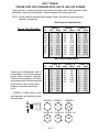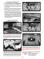
1
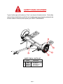
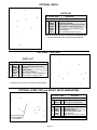
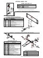
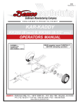
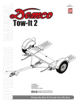
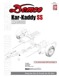
09-25-00 RD20006, Rev 2 Dethmers Manufacturing Company DOING OUR BEST TO PROVIDE YOU THE BEST TOW-IT TI110 & TI110SB TOW DOLLY OPERATORS MANUAL READ complete manual CAREFULLY BEFORE attempting operation. ASSEMBLY CALIBRATION OPERATION REPLACEMENT PARTS DEMCO Dethmers Mfg. Co. 4010 320th St. P.O. Box 189 Boyden, IA 51234 PH: (712) 725-2311 or (712) 725-2302 Toll Free: 1-800-543-3626 FAX: 1-800-845-6420 www.demco-products.com Page 1 IMPORTANT We have discovered 1992 and newer model cars that are too wide in the body area to properly fit on a TI110 - 8' wide tow dolly even though the front tire measurement is less than 70". The 1992 and newer Oldsmobile 88 and 98 are in this category, there may be others. In addition to the standard measurement, always follow weight limitations when using a Demco TOW-IT Tow Dolly. TI100 - Standard Unit 3350 lbs. - Total Towed Vehicle Weight TI110SB - Brake Unit 3500 lbs. - Total Towed Vehicle Weight WARNING: Exceeding weight limitations or not using a towing vehicle larger and at least 1,000 lbs. heavier than the tow dolly and the towed vehicle combined can result in loss of towing vehicle control, separation of the tow dolly from the towing vehicle, or separation of the towed vehicle from the tow dolly, causing severe personal injury, death, or property damage. CAUTION: All vehicles to be towed on Demco Tow Dollies must be towed with the front axle on the dolly. Table of Contents General information ............................................................................................................. 2 Safety , Signal Words ......................................................................................................... 3 Equipment Safety Guidelines .............................................................................................. 4 Lighting and Marking ........................................................................................................... 4 Safety Sign Locations ......................................................................................................... 5 Safety Sign Care ................................................................................................................ 6 Tire Safety .......................................................................................................................... 6 Remember .......................................................................................................................... 6 Before Operation ................................................................................................................. 7 During Operation ............................................................................................................... 7-8 Following Operation ............................................................................................................ 8 Highway and Transport Operations ...................................................................................... 8 Performing Maintenance ..................................................................................................... 9 Bolt Torque ......................................................................................................................... 10 Additional Safety Information ............................................................................................. 11 Testing Lights ..................................................................................................................... 12 Loading Instructions ........................................................................................................ 12-14 Damage Prevention ........................................................................................................... 14 Rear Wheel Drive Precautions ............................................................................................ 14 Limited Warranty ................................................................................................................ 15 Tow Dolly Parts List and Breakdown ............................................................................... 16-17 Assembly Instructions .................................................................................................... 18-19 Surge Brake Assembly ...................................................................................................... 20 10 Brake Cluster Parts List and Breakdown ................................................................... 20-21 Actuator Parts List and Breakdown .................................................................................... 21 Optional Kits ................................................................................................................... 22-23 "Reporting Safety Defects" If you believe that your vehicle has a defect which could cause a crash or could cause injury or death, you should immediately inform the National Highway Traffic Safety Administration (NHTSA) in addition to notifying Dethmers Manufacturing Company (DEMCO). Company (DEMCO). If NHTSA receives similar complaints, it may open an investigation, and if it finds that a safety defect exists in a group of vehicles, it may order a recall and remedy campaign. However, NHTSA cannot become involved in individual problems between you, your dealer, or Dethmers Manufacturing NHTSA, U.S. Department of Transportation Washington, D.C. 20590. Page 2 To contact NHTSA, you may either call the Auto Safety Hotline toll-free at 1-800-424-9393 (or 366-0129 in Washington, D.C. area) or write to: You can also obtain other information about motor vehicle safety from the Hotline. SAFETY TAKE NOTE! THIS SAFETY ALERT SYMBOL FOUND THROUGHOUT THIS MANUAL IS USED TO CALL YOUR ATTENTION TO INSTRUCTIONS INVOLVING YOUR PERSONAL SAFETY AND THE SAFETY OF OTHERS. FAILURE TO FOLLOW THESE INSTRUCTIONS CAN RESULT IN INJURY OR DEATH. THIS SYMBOL MEANS ATTENTION BECOME ALERT YOUR SAFETY IS INVOLVED! SIGNAL WORDS Note the use of the following signal words DANGER, WARNING, and CAUTION with the safety messages. The appropriate signal word for each has been selected using the following guidelines: DANGER: Indicates an imminently hazardous situation that, if not avoided, will result in death or serious injury. This signal word is to be limited to the most extreme situations typically for Tow It components which, for functional purposes, cannot be guarded. WARNING: Indicates a potentially hazardous situation that, if not avoided, could result in death or serious injury, and includes hazards that are exposed when guards are removed. It may also be used to alert against unsafe practices. CAUTION: Indicates a potentially hazardous situation that, if not avoided, may result in minor or moderate injury. It may also be used to alert against unsafe practices. If you have questions not answered in this manual, or require additional copies, please contact your dealer or Dethmers Mfg. Co., P.O. Box 189, 4010 320th Street, Boyden, IA 51234 ph: (712) 725-2311 or (712) 725-2302 Toll Free: 1-800-543-3626 Fax: (712) 725-2380 http://www.demco-products.com Page 3 SAFETY...YOU CAN LIVE WITH IT EQUIPMENT SAFETY GUIDELINES Every year many accidents occur which could have been avoided by a few seconds of thought and a more careful approach to handling equipment. You, the operator, can avoid many accidents by observing the following precautions in this section. To avoid personal injury, study the following precautions and insist those working with you, or you yourself, follow them. Replace any caution, warning, danger or instruction safety decal that is not readable or is missing. Location of such decals is indicated in this booklet. Do not attempt to operate this Tow It under the influence of alcohol or drugs. Review the safety instructions with all users. Operator should be a responsible adult. DO NOT ALLOW PERSONS TO OPERATE OR ASSEMBLE THIS UNIT UNTIL THEY HAVE DEVELOPED A THOROUGH UNDERSTANDING OF THE SAFETY PRECAUTIONS AND HOW IT WORKS. Do not paint over, remove, or deface any safety signs or warning decals on your Tow It . Observe all safety signs and practice the instructions on them. Never exceed the limits of a Tow It. If its ability to do a job safely is in question DON'T TRY IT. LIGHTING AND MARKING It is the responsibility of owner to know lighting and marking requirements of local highway authorities and to install and maintain equipment to provide compliance with regulations. Light bar kits are available from your dealer or from manufacturer. Page 4 SAFETY SIGN LOCATIONS Types of safety sign and locations on Tow It are shown in illustration below. Good safety requires that you familiarize yourself with various safety signs, type of warning, and particular function related to that area, that requires your SAFETY AWARENESS. 3 2 5 4 1 SAFETY DECAL PARTS LIST REF. NO. PART NO. 1. 2. 3. 4. 5. 04508 04804 RD21007 DD21016 DA21001 DESCRIPTION Amber Reflector Red Reflector Instructions Winch Operation Tire Pressure Page 5 SAFETY SIGN CARE Keep safety signs clean and legible at all times. Replace safety signs that are missing or have become illegible. Replacement parts that displayed a safety sign should also display current sign. Safety signs are available from your distributor, dealer parts department, or factory. How to install safety signs: Be sure installation surface is clean and dry. Decide on exact position before you remove backing paper. Remove smallest portion of split backing paper. Align decal over specified area and carefully press small portion with exposed sticky backing in place. Slowly peel back remaining paper and carefully smooth remaining portion of decal into place. Small air pockets can be pierced with a pin and smoothed out using piece of decal backing paper. TIRE SAFETY Failure to follow proper procedures when mounting a tire on a rim can produce an explosion which may result in serious injury or death. Do not attempt to mount a tire unless you have proper equipment and experience to do the job. Inflating or servicing tires can be dangerous. Whenever possible, trained personnel should be called to service and/or mount tires. Tow It tires must be inflated to recommended P.S.I. . See decal on Tow It for correct pressure. Always order and install tires and wheels with appropriate type and load capacity to meet or exceed gross weight of unit. REMEMBER Your best assurance against accidents is a careful and responsible operator. If there is any portion of this manual or function you do not understand, contact your local authorized dealer or manufacturer. Page 6 BEFORE OPERATION: Carefully study and understand this manual. Keep wheel and lug nuts tightened to specified torque. Assure tires are inflated evenly. Give unit a visual inspection for any loose bolts, worn parts, or cracked welds, and make necessary repairs. Follow maintenance safety instructions included in this manual. Be sure there are no tools lying on or in Tow It. Do not use unit until you are sure that area is clear, especially around children and animals. Don't hurry learning process or take unit for granted. Ease into it and become familiar with your new Tow It. Practice operation of your Tow It and its attachments. Completely familiarize yourself and other operators with its operation before using. Make sure that brakes are evenly adjusted (if equipped with brakes) Securely attach to towing vehicle. Use an appropriately sized and rated hitch ball and attach safety chains. Do not allow anyone to stand between tongue or hitch and towing vehicle when backing up to unit. Make sure tow rating on vehicle is high enough for what it is towing. DURING OPERATION SAFETY CHAIN - Always follow state and local regulations regarding safety chains and auxiliary lighting when towing. Be sure to check with local law enforcement agencies for your own particular regulations. Only safety chains (not elastic or nylon/plastic tow straps) should be used to retain connection between towing vehicle and towed unit in event of separation. Do not load towed vehicle with cargo. Towed vehicles exceeding weight limits will overload Tow It and may cause serious injury and damage. Criss cross safety chains under tongue, secure to mounting loops on towing vehicle. Secure emergency brake actuator cable to mounting loop on towing vehicle. Beware of bystanders, PARTICULARLY CHILDREN! Always look around to make sure it is safe to start engine of towing vehicle or move unit. This is particularly important with higher noise levels, as you may not hear people shouting. NO PASSENGERS ALLOWED- Do not carry passengers anywhere on or in towed unit. When halting operation, even periodically, set towing vehicle parking brake, shut off engine, and remove ignition key. Be extra careful on inclines. Page 7 MANEUVER TOWING VEHICLE AT SAFE SPEEDS. DO NOT EXCEED 45 M.P.H. Avoid overhead wires or other obstacles. Contact with overhead lines could cause serious injury or death. Avoid loose gravel, rocks, and holes; they can be dangerous for unit operation or movement. Allow for unit length when making turns. Do not work under raised components or attachments unless securely positioned and blocked. Keep all bystanders and pets clear of work area. Operate towing vehicle from operators seat only. As a precaution, recheck hardware on Tow It every 50 miles, and correct all problems. Follow maintenance safety procedures. FOLLOWING OPERATION Following operation, or when unhitching, stop towing vehicle, set parking brake, shut off engine and remove ignition key. Store Tow It in area away from human activity. Do not permit children to play on or around stored Tow It. Make sure parked Tow It is on hard, level surface. Wheel chocks may be needed to prevent unit from rolling. HIGHWAY AND TRANSPORT OPERATIONS Adopt safe driving practices: - Always drive at safe speed relative to local conditions and ensure that your speed is low enough for an emergency stop. Do not exceed 45 M.P.H. - Reduce speed prior to turns to avoid risk of overturning. - Always keep towing vehicle in gear to provide engine braking when going downhill. Do not coast. - Do not drink and drive! Comply with state and local laws governing highway safety. Local laws should be checked for all highway lighting and marking requirements. Page 8 Plan your route to avoid heavy traffic. Be a safe and courteous driver. Always yield to oncoming traffic in all situations, including narrow bridges, intersections, etc. Watch for obstructions overhead and to both sides while transporting. Operate with maximum visibility at all times. Make allowances for increased length and weight of Tow It when making turns and stopping. PERFORMING MAINTENANCE Good maintenance is your responsibility. Poor maintenance is an invitation to trouble. Make sure there is plenty of ventilation. Never operate engine of towing vehicle in a closed building. Exhaust fumes may cause asphyxiation. Before working on Tow It, stop towing vehicle, set parking brake, turn off engine and remove ignition key. Always block wheels and never use a jack as sole support. Always use proper tools or equipment for job at hand. Use extreme caution when making adjustments. Follow torque chart in this manual when tightening bolts and nuts. Openings in skin and minor cuts are susceptible to infection from brake fluid. Without immediate medical treatment, serious infection and reactions can occur. After servicing, be sure all tools, parts and service equipment are removed. Do not allow grease or oil to build up on any step or platform. When replacing bolts, refer to owners manual for proper size and grade. Refer to bolt torque chart for head identification marking. Where replacement parts are necessary for periodic maintenance and servicing, genuine factory replacement parts must be used to restore your Tow It to original specifications. Manufacturer will not claim responsibility for use of unapproved parts and/or accessories or other damages as a result of their use. If Tow It has been altered in any way from original design, manufacturer does not accept any liability for injury or warranty. A fire extinguisher and first aid kit should be kept readily accessible while performing maintenance on this Tow It. Page 9 BOLT TORQUE TORQUE DATA FOR STANDARD NUTS, BOLTS, AND CAP SCREWS. Tighten all bolts to torques specified in chart unless otherwise noted. Check tightness of bolts periodically, using bolt chart as guide. Replace hardware with same grade bolt. NOTE: Unless otherwise specified, high-strength Grade 5 hex bolts are used throughout assembly of equipment. Bolt Torque for Standard bolts * Torque Specifications A GRADE 2 lb-ft (N.m) GRADE 5 lb-ft (N.m) GRADE 8 lb-ft (N.m) 1/4 5/16 3/8 7/16 1/2 9/16 5/8 3/4 7/8 1 6 10 20 30 45 70 95 165 170 225 9 18 30 50 75 115 150 290 420 630 12 25 45 80 115 165 225 400 650 970 (8) (13) (27) (40) (60) (95) (130) (225) (230) (300) (12) (25) (40) (70) (100) (155) (200) (390) (570) (850) (16) (35) (60) (110) (155) (220) (300) (540) (880) (1310) Bolt Torque for Metric bolts * A Torque figures indicated are valid for non-greased or non-oiled threads and heads unless otherwise specified. Therefore, do not grease or oil bolts or cap screws unless otherwise specified in this manual. When using locking elements, increase torque values by 5%. 6 7 8 10 12 14 16 18 20 22 24 CLASS 8.8 lb-ft (N.m) CLASS 9.8 lb-ft (N.m) CLASS 10.9 lb-ft (N.m) 9 15 23 45 78 125 194 268 378 516 654 10 18 25 50 88 140 216 ----- 13 21 31 61 106 170 263 364 515 702 890 (13) (21) (31) (61) (106) (169) (263) (363) (513) (699) (886) (14) (24) (34) (68) (118) (189) (293) ----- * GRADE or CLASS value for bolts and capscrews are identified by their head markings. GRADE-2 GRADE-5 GRADE-8 CLASS 8.8 CLASS 9.8 CLASS 10.9 8.8 Page 10 9.8 10.9 (17) (29) (42) (83) (144) (230) (357) (493) (689) (952) (1206) WARNING: FAILURE TO FOLLOW THESE INSTRUCTIONS CAN RESULT IN LOSS OF TOWING VEHICLE CONTROL, SEPARATION OF THE TOW DOLLY FROM THE TOWING VEHICLE, SEPERATION OF THE TOWED VEHICLE FROM THE TOW DOLLY, CAUSING SEVERE PERSONAL INJURY, DEATH, OR PROPERTY DAMAGE. SAFETY MAINTENANCE Safety is of utmost importance at all times. There are several items that must be checked each time before using and while using the Tow-It. Periodically check all bolts and nuts to ensure proper tension or torque. Make sure all bolts are properly tightened and those requiring a set torque are up to specifications: Lug Nuts - 75 to 80 ft./lbs. Check Lug Nut tension after the first 5 miles and periodically thereafter. The ball hitch must latch securely around the ball and the safety lock pin or lever must be in position to lock the hitch on the ball. RECOMMENDED BALL HEIGHT: 18 inches to the top of the ball on the towing vehicle. An occasional drop of oil may be required on the moving parts of the tie down winches. Grease the center pivot pin grease zerk every 1500 miles. Grease the main frame platform skids every 1500 miles. These grease zerks are readily accessible from under the front tire stop main platform. Grease the Sure LubeTM Hubs every 3,000 miles. Hook the towed vehicle safety chains to the frame of the vehicle directly above the area where the chain is mounted on the Tow-It. Leave some slack in the chain to allow suspension movement. Use High Quality Bearing Grease with Hand Operated Grease Gun. Check to make sure that all lights are in proper working order. Examine the winches and straps, making sure they are in good conditon. Be certain the safety lock pins are locking the strap winches. IMPORTANT LOADING INSTRUCTION Check your wheel tie-down straps. Retighten straps over the tires after the first 5 miles and every 50 miles thereafter. Ensure that they are tight. Your Tow-It is equipped with custom made wheel tie-down straps of a standard size that will fit most tires, however if your tires are too large or too small you will want to exchange these new straps for the proper size straps. The TI110 tires must be inflated to the recommended 35 PSI. The TI110SB tires must be inflated to the recommended 50 PSI. The strap on the optional tongue winch must be in good condition and should be stored neatly on winch when not in use. NOTE: The winch strap must not be left connected to the towed vehicle after it is loaded and strapped down. Make sure the optional light bar is fastened securely at the rear of the towed vehicle. The wires to the optional light bar should be run along the car and fastened so as not to damage the finish of the towed vehicle. NOTE: This unit cannot be backed up when loaded. All vehicles mounted on the Tow-It must be mounted with the front of the vehicle facing forward. Rear Wheel Drive: Disconnect the towed vehicle driveshaft for rear wheel drive vehicles with automatic transmission. For manual transmission: Consult your vehicle owners manual for towing suitability with the drive shaft connected. Page 11 1. Tire too large - This is very obvious. The strap will not basket over the tire properly; call us, we will provide at NO Charge on an exchange basis, the proper size strap. You must return your new unused straps and provide us with the Make and Model of your car and the tire size. 2. Tire too small - This is not as obvious. The basket will fit down over the tire very well; the problems cannot be readily seen. You must tighten the straps down solid and then check on the inside of the tire and be sure the strap, when tightened, does not come in contact with any metal that may cause wear or cutting such as strut mounts. If there is contact, you need a smaller strap, call us, we will provide on a NO Charge, exchange basis, the proper size strap. You must return your new unused straps and provide us with the Make and Model of your car and tire size. Thank you for Purchasing Products. TESTING LIGHTS BEFORE USE 1. Check that the WHITE (ground) wire of the wiring harness is connected to the Tow-It frame and the WHITE (ground) wire is connected to the frame of the towing vehicle. 2. With headlights in "ON" position, the tail lights, the light cluster bar, the license plate light, and the clearance lights should be lighted. 3. Start engine and have someone depress brake pedal. Brake lights of tow dolly and towing vehicle should come "on" and "off" simultaneously with each application. 4. Turn left turn signal on. Left turn light of Tow-It and towing vehicle should flash simultaneously. Should the turn signal lights of the trailer function opposite to those of the towing vehicle, it is probable that the YELLOW and GREEN wires have been reversed. Check the plug connection under the tongue of the Tow-It to make sure wire colors are not crossed at that point. If plug connection is incorrect, correct problem by reversing yellow and green wire connection on the towing vehicle. Step 3. To allow the wheel platform to tilt back for loading: 1) Swing the bottom of the locking latch (C) toward the hitch far enough to allow locking pin handle to be lifted. LOADING INSTRUCTIONS Refer to load limits on inside of front cover. 2) Pull locking pin toward the hitch as far as it will go. The wheel platform will tilt back to allow loading. Step 1. Secure ball coupler to 2" (3,500 lb. capacity) towing vehicle ball only. Make sure that the hitch and the hitch ball are in good condition and not rusted, loose or stripped. Recommended ball height is 18" to the top of the ball. Make sure hitch is locked down and secured with safety clip. Criss-cross safety chains under tongue and secure to towing vehicle frame. Step 4. Before loading (and unloading) towed vehicle make sure platform and towed vehicle are in straight alignment. Tow dolly must be completely and properly hooked up to the towing vehicle. Towing vehicle must be larger and at least 1000 lbs. heavier than the tow dolly and towed vehicle combined. Step 2. Ensure that towed vehicle parking brake is fully engaged, then release the tie-down straps. NOTE: Tie down straps must be "quick -released" by grasping ratchet pawl and ratchet handle simultaneously and pushing down sharply. This process will permit easy removal of strap from winch.Remove tie-down strap hook from its storage position at the rear of the ramp. Lay the straps on the ground in front of the winches. IMPORTANT: Tire tread width or body width of towed vehicle must not exceed: TI110 - 70" max. (outside to outside), TI110SB 42" min. (inside to inside), 70" max. (body width) Page 12 Step 7. Place one tie-down strap over each tire and secure hooks to rods located at the rear of each wheel platform. The short side of the hook must face the rear of the TOW-IT. Step 5. With someone safely guiding you, slowly drive vehicle onto platform FRONT FORWARD. (Any vehicle mounted on tow dolly must be mounted with front of the vehicle facing forward.) Drive the car forward until the tires touch the ramps. Make sure the tire is aligned to ascend onto the ramps. Step 6. Drive vehicle onto platform - Front Forward - until tires touch the wheel stops at the front of each side of the platform and the platform tilts to a flat position. Make sure the car is centered on the platform. Towed vehicle tires must fit in wheel troughs without overhanging sides. Engage towed vehicle parking brake. Shift loaded car into "park" and lock steering wheel with front tires in a straight position. If the car does not have a locking steering column the steering wheel must be tied securely with front tires in a straight position. Step 8. Be sure tie-down winch is centered with the tire before tightening straps. Step 9. While tightening straps, pull cross strap forward to ensure even tightening. Tighten straps until each tire starts to flatten against tire stop. After each strap is tight, insert a safety pin in each winch. Disengage towed vehicle parking brake. Straps must be retightened after first 5 miles of travel. Check straps every 50 miles thereafter to ensure they are tight and not rubbing or fraying. Rear Wheel Drive: Disconnect towed vehicle driveshaft for rear wheel drive vehicles with automatic transmission. For manual transmission: Consult your vehicle owners manual for towing suitability with the drive shaft connected. IMPORTANT: Lock the platform in position by pushing locking pin toward platform. Push the handle down as far as possible so locking latch holds it in a locked down position. Page 13 (continue with Step 10 on following page) Step 10. Make sure the tie-down strap is the correct size for the auto tire. The picture above shows a correct fitting strap. See page 1 of this instruction for proper fit and exchange instructions. Step 13. To pull the TOW-IT empty, make sure tie-down straps are tightened in the storage position, and towed vehicle safety chains are wrapped up and hooked. Tiedown winch handles should be left in a down position (horizontal) with safety pins in place when towing loaded or empty. DO NOT ATTEMPT TO PULL TOW-IT WITH WHEEL PLATFORM IN LOADING (tilted) POSITION. DAMAGE PREVENTION Check your vehicle manual or registration for vehicle weight. Towing vehicle must be larger and at least 1,000 lbs. heavier than the towed vehicle and tow dolly combined. Do not pack goods in car that is being towed. Overloading the Tow-It or exceeding the width limit may result in damage to both car and Tow-It. REAR WHEEL DRIVE PRECAUTIONS Step 11. Hook the towed vehicle safety chains to frame of vehicle directly above the area where the chains are mounted on the TOW-IT. Leave some slack in the chains to allow suspension movement of the towed vehicle. Review the safety points on page 1 before moving vehicles. Disconnect towed vehicle driveshaft for rear wheel drive vehicles with automatic transmission. Simply placing transmission in neutral is not sufficient to prevent damage to transmisssion. For manual transmission, consult your vehicle owners manual for towing suitability with the drive shaft connected. ALL VEHICLES MOUNTED ON THE TOW-IT MUST BE WITH THE FRONT OF THE VEHICLE FACING FORWARD. SAFETY - - - Step 12. TO UNLOAD towed vehicle. Make sure that platform and vehicle are straight. Reinstall driveshaft. Ensure that towed vehicle parking brake is fully engaged, then unhook the towed vehicle safety chains, and release the tie-down straps. NOTE: Tie down straps must be "quick -released" by grasping ratchet pawl and ratchet handle simultaneously and pushing down sharply. This process will permit easy removal of strap from winch.Swing the wheel platform locking latch handle forward, towards the coupler. This will allow the platform to tilt as you slowly drive off. Make sure the winch ratchet handles are horizontal. Page 14 Examine winches and straps to make sure they are in good condition. Check wheel nuts every trip. Tires must be inflated to recommended pressure by tire manufacturer. Be certain the safety lock pins lock the strap winches. Retighten the straps over the tires after the first 5 miles of travel. Check straps every 50 miles thereafter to ensure they are tight and not rubbing or fraying. DEMCO PRODUCTS - TOW-IT Tow Dolly ORIGINAL PURCHASERS LIMITED WARRANTY 1. Extent and Duration of this Warranty: Your Demco Tow-It is warranted to be free from defects in materials and workmanship under normal use and service for a period of one year after date of purchase by the original (first) retail owner, or until it is resold or transferred by the original owner. Tires and lights are not included in this warranty. This warranty does not cover: 1) normal wear and tear 2) road film or gravel damage to paint 3) paint 4) rust damage 5) Any Demco Tow-It that has been loaded in excess of the load capacity stated on the tow dolly identification label. Tires are warranted by the manufacturer against defects in materials and workmanship, but not against road hazards. Warrantor has a policy of continuous product improvement. We reserve the right to change or improve the design of any Demco Tow-It model, including but not limited to state of the art changes, without assuming any obligation to modify any tow dolly previously manufactured. Any part of the Demco Tow-It, except tires and lights, found in the judgement of the manufacturer to be defective in materials or workmanship will be repaired or replaced at the manufacturerís option without charge for parts or labor to the original owner. Warrantor assumes no responsibility to the owner for loss of use of the tow dolly, loss of time, inconvenience or other damage consequential or otherwise, including, but not limited to expense for gasoline, expense of transporting the tow dolly to the dealer and expense of returning the tow dolly, mechanicís travel time, telephone or telegram charges, road service/towing charges, rental of another tow dolly during the time warranty repairs are being performed, travel, lodging, loss or damage to personal property or loss of revenue or earnings. 2. Manufacturer and Warrantor of Tow Dolly: Dethmers Manufacturing Co. 4010 320th Street P.O. Box 189 Boyden, IA 51234 (712) 725-2311 The manufacturer and warrantor of the tires has his name permanently molded into the tires. Tire warranty questions and claims can be taken directly to an authorized dealer of the tire manufacturer. 3. Repair or Replacement Procedure: If your Demco Tow-It develops a defect (except for tires or lights) during the warranty period, promptly notify Dethmers Manufacturing Co. customer service department. Until such notice is received, Warrantor will not be responsible for any repair or replacement. Upon receipt of notice from you, Warrantor will have a choice of options in replacing any part it determines to be defective: a) Warrantor may require you at your own expense to deliver or ship the part to its factory or authorized dealer. Any defective part will be repaired or replaced and returned to you free of charge. Any part returned to Warrantor and found not to be defective will be returned to you freight collect with an explanation. b) Warrantor may elect to ship a new part to its dealer to be exchanged free of charge for the defective part returned by you to the dealer. c) Warrantor may elect to ship or deliver a replacement part to your address. Warranty claims on tires should be presented to a local authorized dealer of the tire manufacturer. Provide proof of purchase when making a tire warranty claim. 4. Limitations on Warranty Coverage: Coverage under this warranty will be effective only when a copy of the original invoice, showing the date and location of purchase, accompanies any claim for warranty. 5. Limitations of Implied Warranties: All implied warranties, if any, expire and terminate upon expiration of this warranty. Some states do not allow limitation on how long an implied warranty lasts, so this limitation may not apply to you. 6. Limitation of Consequential Damages: Warrantorís responsibility under this warranty extends solely to repair or replacement of your Demco Tow-It and its component parts. Warrantor does not assume responsibility for, nor shall it be liable for, any special, incidental or consequential damages. Some states do not allow the exclusion or limitation on incidental or consequential damages, so the above exclusion or limitation may not apply to you. 7. Use of Vehicle Identification Number (VIN): The VIN is a 17 digit number located in the lower left corner of the tow dolly identification label. The label is located on the left side of the tow dolly frame. Be sure to include the VIN number in all communications with Warrantor or its dealers concerning the warranty. 8. Purchaserís Rights: This warranty gives you specific legal rights, and you may also have other rights which vary from state to state. 9. Exclusive Warranty: This is the only express warranty made by Dethmers Manufacturing Co. on your Demco Tow-It and no agent, employee, or other person is allowed to change or add to this warranty. Warrantor has no liability whatsoever and this warranty is null and void if any Demco Tow-It has been misassembled or subjected to neglect, negligence, misuse, accident or operated in any way contrary to the operating and maintenance instructions as specified in the Demco Ownerís Manual for that model tow dolly. This warranty does not cover any tow dolly that has been altered or modified so as to affect the tow dollyís operation, performance or durability, or that has been modified to change the intended use of the tow dolly. In addition, the warranty does not extend to repairs made necessary by normal use of parts, accessories or other equipment which in the judgment of Warrantor, are either incompatible with the Demco Tow-It, or affect its operation, performance or durability. Page 15 REF. QTY. NO. PART NO. REQíD DESCRIPTION 1. 2. 3. 4. 5. 6. 7. 8. 9. 10. 11. 12. 13. 14. 15. 16. 17. 18. 19. 20. 21. 22. 23. 5432 5433 03569-95 03570-95 03571-95 03577 03574-95 03668 03575-95 03576-95 03666 02243 05450 01864 05449 00004 05444 03572-95 03573-95 03578 01998 02002 02772 01076 00214 05337 1 1 1 1 1 1 1 1 1 1 1 1 1 2 1 1 1 1 1 1 1 1 2 1 1 1 Left Ratchet Winch Assembly (Plated) Right Ratchet Winch Assembly (Plated) Ratchet Frame Left Spool Tube Right Spool Tube Heavy Duty External Snap Ring Ratchet Handle 18 Ga. Shim Washer Left Ratchet Gear Right Ratchet Gear 5/16" x 1-1/4" Roll Pin Black Vinyl Hand Grip Winch Pawl Winch Pawl Spring SS Winch Pawl Bushing SS 5/16" Flatwasher 3/8"-16 UNC x 3/4" Hex Bolt w/epoxy Gr.5 Left Ratchet Pawl Arm Right Ratchet Pawl Arm 5/16"-18 UNC x 1/2" Shoulder Screw 5/16" Flatwasher SS 1/4" Flatwasher SS 1/4"-20 UNC Nylon Locknut 1/4"-20 UNC x 3/4" Hex Hd. Bolt Gr.5 1/4" Flatwasher Lock Pin w/Cable 24. 25. 26. 27. 28. 29. 30. 31. 32. 33. 34. 35. 36. 37. 38. 39. 40. 41. 42. 43. 44. 45. 46. 47. 48. 49. 50. 51. 52. 53. 54. 55. 56. 57. 58. 59. 60. 61. 62. 01883 01881 04785 04786 01863 04496 01855 01338 02288-95 02189 02178 02771 01853 04194 00059 01898 04792-26 02587 02434 03503 02747-25 01254 00085 02579-95 04825 02574-95 02583 04780-26 02209 02377 04782 01725 04826 04323-25 00967 04168 04167 02592 05358 05357 04425 9 1 1 1 2 1 1 2 1 1 12 2 2 12 4 1 1 1 2 2 2 11 2 1 1 1 1 8 8 2 10 2 2 8 6 6 14 1 1 4 Electrical Wire Splicer Trunk Connector Front Half Trailer Wiring Harness Rear Half Trailer Wiring Harness 5/8" Grommet Lever Lock Coupler (5,000 lb.) Safety Lock Pin for coupler 1/2"-13UNC x 4-1/2" Hex Head Bolt (gr.5) Handle 1/2" I.D. Handle Grip 1/2"-13UNC Nylon Insert Locknut 7/16"-14UNC Nylon Insert Locknut 24" Safety Chain with Hook 7/16" "S" Hook for safety chains 3/8" Flatwasher 7/16"-14UNC x 1-1/4" Hex Head Bolt (gr.5) Tongue 5/8"-11UNC Nylon Insert Locknut 5/8"-11UNC x 4-1/2" Hex Head Bolt (gr.5) 5/8"-11 UNC x 1-1/4" Hex Hd. Epoxied Bolt Bracing Strut 1/2-13UNC x 1-1/2" Hex Head Bolt (gr.5) 1/2" Flatwasher Pivot Bushing 3/8" I.D. x 1/2" O.D. Grommet Lock Pin (Tongue) 3/16" x 1-1/4" Roll Pin Undercarriage (09533-26 for TI110SB) 7/16"-20UNF Hex Nut (gr.8) 7/16"-20UNF x 1-1/2" Epoxied Bolt (gr.8) 14 x 6 rim (5 on 4-1/2" BC) 1/2"-20UNF Chrome Lug Nut ST205/75R14 "C" Range BW Radial Tire Tilt Bed Ramp 1/2"-13UNC x 1-1/4" Hex Head Bolt (gr.5) 7/16"-20UNF Nylon Insert Locknut 7/16"-20UNF x 1" Hex Head Bolt (gr.8) 3/8"-16UNC Nylon Insert Locknut Left Fender (w/ wire protector & gr. wire) Right Fender (w/ wire protector & gr. wire) Tinnerman Fender Clamp REF. QTY. NO. PART NO. REQíD 63. 64. 65. 66. 67. 68. 69. 70. 71. 72. 73. 74. 75. 76. 77. 78. 79. 80. 81. 82. 83. 84. 85. 86. 87. DESCRIPTION 02298 05443 04944 04508 02316 04424-95 00914 04804 02313 05447 05446 04781-26 03528 01674 02383 04194 04270-25 00907 05570 02578-95 02584 04083 5341-26 04499 00078 07426 2 2 2 2 2 2 6 2 2 2 2 1 2 4 2 2 8 1 1 1 1 2 6 2 4 22-1/2" Wire Protector Cable Hanger - wire harness Wire Strain Relief Amber Fender Reflector White Ground Wire Back-Up Plate for fender 3/8"-16UNC x 1-1/2" Hex Head Bolt (gr.5) Red Fender Reflector 3-way Plug Pigtail (tail light) Rubber Mounting Grommet for light Sealed Round Tail Light Upper Half Mainframe 3-point Tie-Down Strap w/J-Hook & buckle 1/4" Drive Type Grease Zerk 36" Safety Chain with hook 7/16" "S" Hook for safety chains Rear Tire Stop 3/8"-16UNC x 1" Hex Head Bolt (gr.5) 1/2"-13UNC x 1" Epoxied Bolt (gr.5) w/zerk 1/2" Special Flatwasher 3/16" x 3/4" Roll Pin 1-3/4" O.D. Bronze Bushing SureLubeTM Hub and Spindle Assembly 3/8 External Tooth Washer 7/16 Lock Washer Hook Retainer 5341 89. 01747 90. 01743 91. 01744 92. 01745 93. 01748 94. 02264 95. 02265 96. 02266 97. 02267 98. 00116 99. 04789 100. 01746 101. 04790-26 2 1 1 1 1 1 1 1 1 1 1 1 5 1 Sure LubeTM Hub Assembly Hub Grease Seal (NOK AD 2548 E) Inner Cup (L68111) Inner Cone Bearing (L68149) Outer Cup (L44610) Outer Cone Bearing (L44643) Hardened Tongue Washer 13/16-20 UNF Jam Nut Retainer Adjustment Washer for Jam Nut 5/32" x 1-1/2" Cotter Pin Sure Lube Dust Cap 1/2"-20UNF x 1-5/8" lg. Stud Bolt Spindle Please order replacement parts by PART NO. and DESCRIPTION. not included for Fulton 5000 lb. coupler 33 29 5217 Coupler Repair Kit 38 26 28 24 25 35 87 87 Page 16 34 36 37 35 LEFTWINCHSHOWN 23 20 22 21 10 75 6 18 17 44 81 83 2 7 8 36 79 74 86 4 11 9 5 3 12 1413 15 80 12 20 16 19 78 36 37 59 72 73 77 71 61 65 62 87 67 66 1 64 62 63 68 69 59 84 73 72 69 71 68 60 70 49 76 33 44 46 40 45 43 42 85 82 58 57 33 28 48 59 26 47 41 27 45 54 33 51 32 56 50 44 31 44 84 43 41 55 52 42 5341 101 Sure LubeTM Hub Assembly 90 53 100 91 30 92 89 93 95 98 97 94 96 99 Page 17 TOW-IT ASSEMBLY INSTRUCTIONS 1 2 16 17 8 3 9 6 5 18 4 13 10 19 7 14 20 15 11 12 1. Place the mainframe on blocks or some other sturdy support so that the frame rests approximately 8"-10" off the ground. Attach the tilt bed ramps (#1) as shown using three 7/16" x 1" grade 8 bolts (#2) and lock nuts (#3) on the top of each ramp and four 1/2" x 1-1/4" grade 5 bolts (#4), flatwasher (#5) and locknuts (#6) (two on each side of the ramp). Torque the 7/16" bolts to 80 ft. lbs. and torque the 1/2" bolts to 75 ft. lbs. 2. Hold the tongue (#7) up to Pigtail the front of the tow dolly and locate the three bullet Brown Brown/Yellow connectors extending out Yellow the back of the tongue and Green Brown/Green plug into the connector protruding from under the mainframe channel. Do not cross colors when making this connection. 3. Mount the tongue to the front of the tow dolly using one 5/8" x 4-1/2" grade 5 bolt (#8) and locknut(#9) (torque to 50 ft. lbs.). Do not torque over 50 ft. lbs. or the bed will not tilt. Make sure the tongue latch is in the latched position to the tilt bed. 4. Secure the coupler (#10) and lift handle (#11) to the front end of the tongue with two 1/2" x 4-1/2" gr.5 bolts (#12) and locknuts (#13) . The white ground wire (#14) is attached under the head of the second bolt attaching the coupler. (It is very important that a good ground is made). Torque the locknuts to 75 - 80 ft. lbs. Tap a rubber grip (#15) onto the handle with a rubber hammer or a wooden mallet. 5. Remove the 7/16" x 1-1/4" bolt (#16), flatwasher, and locknut from the outer front panel of each wheel platform tire stop. Slide the tie-down winch (#17) into the channel at the front of the wheel platforms as shown. Note that #17 is the left winch. The ratchet handles are to the outside of each winch and ratchet springs are to the top. Attach two 36" towed vehicle safety chains (#18). Secure one chain to each wheel platform tire stop with the 7/16" x 1-1/4" bolt (#16) , flatwasher and locknut. 6. 7. 8. When assembling the tie-down strap to the tow dolly winch, make sure the tie-down strap does not contain any twists and the overlaps are to the inside. Weave the front of the tie-down strap through the openings in the buckle. The buckle should be approximately 8" from the end of the strap. Thread the strap end through the winch slot. Bring the strap up and thread it back through the buckle again. The buckle should be approximately 1-1/2" - 2" from the winch. (Refer to drawing on page 9 for following steps) Attach Hub and Spindle Assembly (#19) using 7/16" x 1-1/4" Fine Thread Bolts (#20) and hex nuts. Bolt the fenders (#21) on using 3/8" x 1-1/2" gr. 5 bolts (#22), back-up plates (#23) and locknuts (#24) in each fender. Mount the fender with the light pocket to the rear. Attach the white ground wire (#25) (the end with the eye loop on it) under the center top bolt head. NOTE: 9. 10. It is advantageous to wire the fender lights prior to attaching the wheels. Cut off stripped ends of the wiring harness, cut off stripped end of the white ground wire. The yellow/brown wires must be run to the left tail light pocket. The green/brown wires must be run to the right tail light pocket. Start at either fender, pull the loom at the center of the fender downward and push the green/ brown (or yellow/brown) wires upward through the loom until it comes out the loom by the light pocket. Push the white ground wire through the slit in the top of the loom in the fender trough and push the wire toward the light pocket. Make sure all three wires are coming out the fender wire loom. Slide the rubber fender grommet over the wires and up close to the wire loom. Push the hollow looped end of the loom hanger into the small hole under the fender pocket in the side of the fender. Leave the holder open. Pull the three wire pigtail wires through the hole in the fender pocket outward. When wiring the pigtail into the tow dolly Page 18 COLOR CODE FOR WIRING HARNESS WHITE Ground BROWN Tail Lights and License Plate Light YELLOW Left Turn and Stop GREEN Right Turn and Stop 21 23 22 25 24 Triple Wire Plug from Light White 22 Wire Connector Red 27 21 26 23 25 White Black White Ground Wire to Fender 33 Brown Yellow or Green 32 31 30 29 WIRING DIAGRAM FOR THE AUTO TRANSPORT FENDER 34 24 Yellow/Brown or Green/Brown 29 34 35 38 35 11. 12. 13. 37 28 36 harness at the fender pocket, the wire ends SHOULD NOT be stripped. Use the wire connectors to make all contacts. Lay the wire in the connector, pinch securely with a pliers, closing the wire connector. Splice the white wire of the pigtail to the white ground wire from the fender. Splice the black wire to the brown wire. Splice the green (or yellow) wire to the red wire of the pigtail. The connections are made on the outside of the fender pocket and pushed into the fender pocket through the pocket hole. Pull the wires back into the fender pocket and push the strain relief into the fender with the wire loom close to the clip. Wrap the loom hanger tie around the wire loom and insert the peg into the fender. 14. Push the round rubber light seal (#26) into the light pocket. Be sure the lip is secured in the light housing. Plug the pigtail into the fender light. Push the round light (#27) into the rubber seal until it snaps in firmly. Wire the other fender in the same manner. 2. Connect YELLOW wire to left turn signal and stop wire in the left rear of towing vehicle with the wire splicer (01883 X) supplied. Attach the tire/rim assembly to the mainframe. Use the supplied lug nuts (#28) and torque to 75 - 80 ft. lbs. Lay the bracing struts (#29) out along the tow dolly tongue with the back end (the end with the larger hole in it) of the bracing strut toward the mainframe. Loosely bolt the back of each bracing strut to the trailer frame as shown using 1/2" x 1-1/2" grade 5 bolt (#30), flatwasher (#31), pivot bushing (#32) and locknut (#33). Hold up the front end (the end with the smaller hole) of each bracing strut to the tongue, align holes and secure with a two 5/8" x 1-1/4" epoxied bolt (#34). Torque the 1/2" x 1-1/2" bolt with the pivot bushing to 75 ft. lbs. Attach the two 24" transport safety chains (#35) to the two holes in the angle located under the tongue using two 7/16" x 1-1/4" grade 5 bolts (#36), flatwashers (#37), and locknuts (#38). Torque bolts to 50 ft. lbs. WIRING OF THE TOWING VEHICLE Connect wiring to towing vehicle, keeping in mind the color code indicated below. 1. Make certain towing vehicle lights are "OFF". 3. Connect GREEN wire to the right turn signal and stop wire. 4. Connect BROWN wire to tail light wire. 5. VERY IMPORTANT - connect WHITE wire to frame body of towing vehicle. This is the common ground, and a clean metal - to - metal contact must be made. CAUTION: Many flashers for vehicle turn signals will not carry the additional load of TOW-IT turn signals. If normal operation does not occur when connected to the TOW-IT, a heavy duty replacement flasher may be obtained through auto parts outlets. Page 19 SURGE BRAKE ASSEMBLY Aftermarket Brake Kit (5592) available factory installed only 11 12 11 10 9 8 22 7 11 12 5 4 24 11 3 Shown Below 6 13 14 15 16 1 21 2 16 18 17 19 20 23 BRAKE LINES PARTS LIST REF. QTY. NO. PART NO. REQíD. 1. 2. 3. 4. 5. 6. 7. 8. 9. 10. 11. 12. 02189 02383 SB580 01863 02746 04792-26 SB7H66 00496 SB7764 SB512 02549 SB544 1 2 1 1 1 1 1 1 1 1 4 2 DESCRIPTION 13. 14. 15. 16. 17. 18. 19. 20. 21. 22. 23. 24. Handle Grip 36" Safety Chain 80" Brake Line 5/8" Rubber Grommet 54" Protective Hose Tongue 7" Brake Hose 5/8 x 14 Ga. Machine Washer Retaining Clip 12" Brake Line Rubber Brake Line Protector 44" Brake Line 4 04791-26 02209 00078 SB8798 00059 00060 00907 04826 04017-95 SB7785 01975 02178 2 6 6 6 4 2 2 2 1 1 2 2 Spindle w/Brake Flange 7/16"-20UNF Hex Nut (Gr.8) 7/16" Lockwasher 7/16"-20UNF x 1-1/8" Knurled Shoulder Bolt 3/8" Flatwasher 3/8" Lockwasher 3/8"-16UNC x 1" Hex Head Bolt (Gr.5) P205/75R14 "C" Range BSW Radial Tire Handle Tee, Brass 1/2 -13 UNC x 5 Hex Head Bolt, Gr. 5 1/2 -13 UNC Nylon Insert Locknut 7 5 16 1 Left Side Breakdown 6 16 3 2 2 8 11 13 10 12 19 9 18 10 17 17 15 14 17 Page 20 18 17 8606701 ACTUATOR PARTS 18 14 13 12 2 10 10 9 8 7 2 7 5 1 6 4 6 2 3 2 ACTUATOR PARTS LIST 15 REF. PART QTY. 19 NO. NO. REQíD. DESCRIPTION 19 16 8606701 1 Brake Actuator complete (incl. ref. 1-24) 26 25 17 1. 07599-95 1 6000# 2" Ball Coupler (Fulton) 25 2. SB23278 4 Roller 20 20 3. 05957-95 1 Front Roller Spacer 4. 02166 1 3/8"-16UNC x 2-3/4" Hex Head Bolt (gr.5) 5. 07176 1 3/8"-16UNC Stover Lock Nut 6. 05684 2 1/2"-13UNC x 4-7/16" Hex Head Bolt (gr.5) 21 7. 02178 2 1/2"-13UNC Nylon Insert Lock Nut 8. 05959 1 Push Rod Assembly 9. 05692 1 Damper/ Shock 10. 05958-95 2 Rear Roller Spacer 11*. 05951 1 Emergency Lever 22 12. 05955-95 1 Front Cover 27 13*. SB24700 1 2' Cable with S-Hooks 11 14. SB10555 2 Replacement S-Hook ONLY 15. 05960 2 5/16"-18UNC x 1/2" Self-Tapping Screw 24 16. 05424 2 5/16" External Tooth Lock Washer 17*. 05693-95 1 Emergency Lever Spring 23 18. 03876 1 Master Cylinder Cap 19. 01076 4 1/4-20UNC x 3/4" Hex Head Bolt Gr 5 20. 00057 2 1/4" Lock Washer 21. 03564-95 1 Outer Case 22. 05681 1 Replacement Master Cyl. Gasket ONLY 23. 5650 1 Composite Master Cylinder Kit w/ 09153 24. SB12098 1 1/8" pipe - 3/16" inverted Flare Fitting not included 25. 05695 2 1/4 Internal Tooth Lock Washer for 26. 05966-95 1 Rear Cover Fulton 27. BH21004 1 Decal, Preset Fasteners 6000 lb. coupler 5398 Master Cylinder Repair Kit (gasket 05681 included) 5495 Coupler Repair Kit - 5400 - Lever Replacement Kit (incl. items w/*) - 5398 - Master Cylinder Repair Kit w/ gasket 5495 - Coupler Repair Kit - Please order replacement parts by PART NO. and DESCRIPTION. 10" BRAKE CLUSTER PARTS LIST REF. PART QTY. NO. NO. REQíD. DESCRIPTION SB23715 Left Hand Cluster (shown above) SB23714 Right Hand Cluster 1. SB24636-30 1 Back Plate Assembly 2. SB9254 2 Cover Plate - Adjusting Hole 3. SB10954 1 Brake Shoe Kit (includes 2 Primary & 2 Secondary) 4. 04305 2 5/16"-18UNC-Gr5 x 1/2" Hex Hd Bolt 5. 05424 2 5/16" External Tooth Washer 6. SB9776 1 Wheel Cylinder Assembly - Right SB9777 1 Wheel Cylinder Assembly - Left 7. 05431 1 Bleeder - replacement 8. SB9783 1 Push Rod 9. SB24047 1 Adjusting Screw Assembly - "R" (for LEFT cluster) SB24048 1 Adjusting Screw Assembly - "L" (for RIGHT cluster) 10. SB10958 2 Spring - Shoe 11. SB10961-95 1 Shoe Guide 12. SB23937 1 Cable 13. SB23936 1 Cable Guide 14. SB23724 1 Spring Adjusting Screw 15. 05414-95 1 Lever - Left 05415-91 1 Lever - Right 16. SB10959 2 Pin - Shoe Hold Down 17. SB9789 4 Cup Shoe Hold Down 18. 05983 2 Spring - Shoe Hold Down 19. 03880 1 Spring - Adjusting Screw Retainer - SB15845 1 Wheel Cylinder Repair Kit (includes spring, cup and boot) - SB15545 4 10" Brake Drum Please order replacement parts by PART NO. and DESCRIPTION. Brake shoe kit can be ordered for one complete axle only. Page 21 10" BRAKE DRUM 10" BRAKE CLUSTER OPTIONAL WINCH 4 PARTS LIST REF. QTY. NO. PART NO. REQíD. 2 5 6 1 1. 2. 3. 4. 5. 6. 3 KK2W 04620 04621 01738 02207 02769 00059 02592 1 1 1 1 2 2 3 DESCRIPTION Optional Winch Winch Mechanism (1400 capacity) Replacement Handle Strap Assembly (includes strap & hook) 3/8"-18UNC x 3" Hex Hd. Bolt (gr.5) 3/8"-16UNC x 4" Hex Head Bolt (gr.5) 3/8" Flatwasher 3/8"-16UNC Nylon Insert Locknut Please order replacement parts by PART NO. and DESCRIPTION. * All options may not mount on tow dolly simultaneously.* 6 OPTIONAL TOOL BOX 7 PARTS LIST 1. 2. 3. 4. 5. 6. 7. KK2TB 00059 02592 01888-25 00182 02717-25 00907 02759 QTY. 4 8 1 1 2 4 2 Optional Tool Box 3/8" Flatwasher 3/8"-16UNC Nylon Insert Locknut Tool Box Small Hair Pin Mounting "Z" Bracket 3/8"-16UNC x 1" Hex Head Bolt (gr.5) 3/8"-16UNC x 3" Square U-Bolt 7 2 2 1 6 Please order replacement parts by PART NO. and DESCRIPTION. 4 5 * All options may not mount on tow dolly simultaneously.* 3 OPTIONAL SPARE TIRE and MOUNT PARTS BREAKDOWN REF. QTY. NO. PART NO. REQíD. 4 6 3 7 8 Drive in stud here for tire with rim #04782 (41/2" bolt circle) 2 1 5 DESCRIPTION - KK10STB 1 Optional Spare Tire and Rim 1. 2. 04826 04782 1 1 ST205/75R 14"x"C" BSW Radial Tire 6" x 14" Rim 4-1/2" Bolt Circle 1 1 1 2 2 2 4 Spare Tire Mounting Bracket Spare Tire Bracket Stud Bolt (12mm x 1.5) Wheel Nut (12mm) 3/8"-16UNC Square U-Bolt 3/8" Flatwasher 3/8"-16UNC Nylon Insert Locknut KK6STM 3. 02193-25 4. 02917 5. 02933 6. 02759 7. 00059 8. 02592 - KK6TC Optional Spare Tire Cover Please order replacement parts by PART NO. & DESCRIPTION. * All options may not mount on tow dolly simultaneously.* Page 22 OPTIONAL WHEEL JACK 3 3 WHEEL JACK PARTS LIST 2 1. 2. 3. 2 KK2WJ 02769 00060 00061 Optional Wheel Jack w/ hardware 4 3/8 UNC x 4 Bolt, Gr. 5 4 3/8 Lock Washer 4 3/8 Hex Head Nut QTY. Please order replacement parts by PART NO. and DESCRIPTION. 1 * All options may not mount on tow dolly simultaneously.* OPTIONAL DEFLECTOR PARTS BREAKDOWN 7 8 5 OPTIONAL DEFLECTOR PARTS LIST REF. NO. PART NO. 1. 2. 3. 4. 5. 6. 7. 8. 9. KK2DF 02592 02759 00161-95 02054-25 00095 02743-25 02165 02161 02055-25 3 QTY. REQíD. DESCRIPTION 4 2 2 1 4 1 1 1 2 4 Optional Deflector 3/8"-16UNC Nylon Insert Lock Nut 3/8"-16UNC Square U-Bolt (fits around 3" tube) Lock Handle Deflector Slide Mount 3/8"-16UNC x 3/4" lg. Square Head Set Screw Deflector Upright Post Deflector Lacing Cord (1/8" x 25 ft.) Deflector Fabric Deflector Framework 9 3 6 1 Please order replacement parts by PART NO. and DESCRIPTION. 2 OPTIONAL LIGHT BAR (KKLB) PARTS BREAKDOWN 7 6 8 1 14 9 8 2 9 1 9 4 REF. PART QTY. NO. NO. REQíD. KKLB 1. 01772 2 2. 01857 1 3. 01773 1 4. 01886 4 5. 02385-25 1 6. 02386-25 2 7. 01856 1 8. 02772 10 9. 00092 6 10. 01777-25 2 11. 01778 4 12. 02198 1 13. 00068 4 14. 01911 15. 01912 - 3 8 LIGHT BAR PARTS LIST 5 DESCRIPTION 8 Kar Kaddy Light Bar (complete) Nylon Security Strap with hooks & tightener Left Tail/ Brake and Signal Light w/Lenses Brown Jumper Wire Wire Holder (metal) Light Bar Framework Adjustable Light Bracket Right Tail/ Brake and Signal Light w/Lenses 1/4"-20UNC Nylon Insert Locknut 1/4"-20UNC x 1/2" Hex Head Bolt Light Bar "Z" Bracket 3" Suction Cup w/Bolt (#13) Light Bar Wiring Harness (new style) 1/4"-20UNC x 3/4" Hex Head Bolt Large Red Lens Small Red Lens 15 9 12 1 13 13 1 10 11 Please order replacement parts by PART NO. and DESCRIPTION. Page 23 11 COLOR CODE FOR WIRING HARNESS WHITE Ground BROWN Tail Lights, License Plate Lights, Light Cluster Bar & Clearance Lights YELLOW Left Turn and Stop GREEN Right Turn and Stop DETHMERS MFG. COMPANY P.O. BOX 189 4010 320th St., BOYDEN, IA. 51234 PH: (712) 725-2311 or (712) 725-2302 FAX: (712) 725-2380 TOLL FREE: 1-800-54DEMCO (1-800-543-3626) www.demco-products.com Page 24