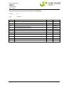
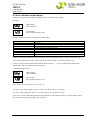
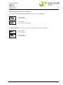
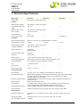
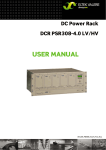
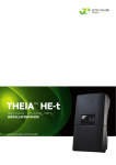
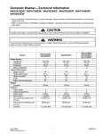
1
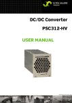
DC/AC INVERTER UNV-F 2.5/3.3/5.0 USER MANUAL UM_UNVF_E_R2.0 DC/AC Inverter UNV-F User Manual Page 2 (28) Notes to this manual ATTENTION! Read this manual very carefully before installing and commissioning the specified module. This manual is a part of the delivered module. Familiarity with the contents of this manual is required for installing and operating the specified module. The rules for prevention of accidents for the specific country and the general safety rules in accordance with IEC 364 must be observed. The function description in this manual corresponds to the date of publishing. Technical changes and changes in form and content can be made at any time by the manufacturer without notice. There are no obligations to update the manual continually. The module is manufactured in accordance with applicable DIN and VDE standards such as VDE 0106 (part 100) and VDE 0100 (part 410). The CE marking on the module confirms compliance with EU standards 2006-95-EG (low voltage) and 2004-108-EG (electromagnetic compatibility) if the installation and operation instructions are followed. Supplier: FAX Email Internet ELTEK VALERE DEUTSCHLAND GmbH GB Industrial Schillerstraße 16 D-32052 Herford + 49 (0) 5221 1708-210 + 49 (0) 5221 1708-222 [email protected] http://www.eltekvalere.com 2009. ELTEK VALERE DEUTSCHLAND GmbH. All rights reserved. ©2009. ELTEK VALERE DEUTSCHLAND GmbH. UM_UNVF_ E_R2.0 DC/AC Inverter UNV-F User Manual Page 3 (28) The current revision status of this user manual is the following: Revision: 2.0 Date: 2009-07-31 Revision Description of change Writer 01-03 Minor text modifications RTH 04 ELTEK VALERE INDUSTRIAL layout inserted RTH 2008-01-29 1.0 New revision status numbering (X.X) introduced, section “Error indication on the displays” inserted. RTH 2009-04-20 2.0 Minor reworking at sections 3.4, 4.2, 7. RTH 2009-07-31 ©2009. ELTEK VALERE DEUTSCHLAND GmbH. Date UM_UNVF_ E_R2.0 DC/AC Inverter UNV-F User Manual Page 4 (28) Table of Contents 1A. SAFETY INSTRUCTIONS ........................................................................................................................................5 1B. ELECTRIC WASTE DISPOSAL ................................................................................................................................5 2. GENERAL INFORMATION ..........................................................................................................................................6 2.1 TYPICAL APPLICATIONS ...........................................................................................................................................6 3. TYPE RANGE/EQUIPMENT ......................................................................................................................................7 3.1 MOUNTING ACCESSORIES.........................................................................................................................................7 3.2 FRONT VIEW/OPERATION ELEMENTS.......................................................................................................................8 3.3 ELECTRICAL CONNECTORS .......................................................................................................................................9 3.3.1 Electrical Connector X1 for UNV-F 2.5 – 3.3kVA, UNV60-5.0F and UNV110-5.0F ...................9 3.3.2 Electrical Connector X1 for UNV48-5.0F (HAN K 6/6).................................................................. 10 3.3.3 CAN-Bus connectors CAN1 & CAN2.................................................................................................. 11 3.4 COOLING/AIR FLOW DIRECTION ............................................................................................................................ 11 3.5 COMMUNICATION INTERFACE ................................................................................................................................ 12 4. HANDLING................................................................................................................................................................ 12 4.1 STORAGE.............................................................................................................................................................. 12 4.2 COMMISSIONING ................................................................................................................................................... 12 4.2.1 Single inverter ........................................................................................................................................ 13 4.2.2 Operation in parallel .............................................................................................................................. 13 4.2.3 CAN-Bus Addressing ............................................................................................................................. 13 4.3 LED INDICATIONS ................................................................................................................................................. 14 4.4 INTERNAL MONITORING ......................................................................................................................................... 15 4.5 ADJUSTMENT OF THE STANDARD AND THRESHOLD VALUES................................................................................... 16 4.5.1 Diagram “Standard display during operation/display of input and output parameters”..... 17 4.5.2 Diagram “Adjustment mode”............................................................................................................... 19 4.5.3 Table “Adjustable Parameters” .......................................................................................................... 21 5. MAINTENANCE........................................................................................................................................................ 22 6. TROUBLE SHOOTING ............................................................................................................................................. 22 6.1 FAILURE TABLE ..................................................................................................................................................... 22 6.2 ERROR INDICATION ON THE DISPLAYS .................................................................................................................... 23 7. TECHNICAL SPECIFICATIONS ............................................................................................................................... 25 7.1 DIMENSIONAL DRAWINGS ...................................................................................................................................... 27 ©2009. ELTEK VALERE DEUTSCHLAND GmbH. UM_UNVF_ E_R2.0 DC/AC Inverter UNV-F User Manual Page 5 (28) 1A. Safety Instructions Warning! Because several components of operating electrical modules are charged by dangerous voltage, the improper handling of electrical modules may be the cause of accidents involving electrocution, injury, or material damages. Operation and maintenance of electrical modules must be performed by qualified skilled personnel such as electricians in accordance with EN 50110-1 or IEC 60950. Install the module only in areas with limited access to unskilled personnel. Before starting work, the electrical module must be disconnected from mains. Make sure that the module is earthed. Do not touch connector pins as they can be charged with dangerous voltage up to 30 seconds after disconnection. Only spare parts approved by the manufacturer must be used. 1B. Electric Waste Disposal Separate collection is the precondition to ensure specific treatment and recycling of waste electrical and electronic equipment and is necessary to achieve the chosen level of protection of human health and the environment. In the case of waste disposal of your discarded equipment we recommend to contact a waste management company. ©2009. ELTEK VALERE DEUTSCHLAND GmbH. UM_UNVF_ E_R2.0 DC/AC Inverter UNV-F User Manual Page 6 (28) 2. General Information Inverters of the series UNV-F convert input side DC voltage to a stable sinusoidal output voltage. The inverters are available for delivery with an output power of 2.5, 3.3 and 5.0 kVA per module. Several units can be switched in parallel operation to increase the system output power. The UNV-F is a hot-pluggable module with rear side connectors. Only the communication wire (CAN-Bus) is connected at the front. The inverters are controlled and monitored by an internal microprocessor. Due to the outstanding switching principle the units have very low losses and therefore very compact dimensions, low weight and a very high power density. All main functional parameters are adjustable with front side operating keys and are indicated with digital displays. To increase the reliability the UNV-F inverter is designed to operate together with a static transfer switch of series UNB. The static transfer switch monitors the connected bypass mains and synchronizes the inverter output with mains frequency. In inverter priority mode the UNB transfers the load supply to bypass mains in case of inverter faults, high overload or battery low voltage. The transfer is nearly without voltage interruption (<4ms). The unit switches back to inverter operation automatically if the reason for the transfer is gone. In case of mains priority mode the inverter will take over the load if the mains voltage is not present, out of limits or heavy disturbed. The priority source is programmable at the UNB unit (see separate manual). 2.1 Typical Applications (a) Inverter in parallel operation without UNB ©2009. ELTEK VALERE DEUTSCHLAND GmbH. b) Inverter in parallel operation with UNB UM_UNVF_ E_R2.0 DC/AC Inverter UNV-F User Manual Page 7 (28) 3. Type Range/Equipment Type designation Material code Nominal Inputvoltage (VDC) Nominal Input current (ADC) Nominal Outputvoltage (VAC) Output frequency (Hz) Outputpower (VA @ cosφ =0.8) Dimensions W/H/D (mm) UNV48-2.5F 500-025-511.00 48 47.3 230 50/60 2500 483/133/360 UNV60-2.5F 500-025-611.00 60 37.9 230 50/60 2500 483/133/360 UNV110-2.5F 500-025-711.00 108 20.4 230 50/60 2500 483/133/360 UNV48-3.3F 500-033-511.00 48 62.5 230 50/60 3300 483/133/360 UNV60-3.3F 500-033-611.00 60 50.0 230 50/60 3300 483/133/360 UNV110-3.3F 500-033-711.00 108 26.7 230 50/60 3300 483/133/360 UNV48-5.0F 500-050-511.00 48 94.7 230 50/60 5000 483/133/440 UNV60-5.0F 500-050-611.00 60 74.9 230 50/60 5000 483/133/440 UNV110-5.0F 500-050-711.00 108 39.9 230 50/60 5000 483/133/440 For more specific data, see section 7. 3.1 Mounting accessories Mounting set for 19’’ cabinet (not for UNV48-5.0F): Mat. code 880-MEC-MKT.01 Mounting set for 19’’ cabinet (for UNV48-5.0F): Mat. code 880-MEC-MKT.02 The mounting set is necessary to fit the UNV module in a 19’’ compatible cabinet (see section 4.2 “commissioning”). ©2009. ELTEK VALERE DEUTSCHLAND GmbH. UM_UNVF_ E_R2.0 DC/AC Inverter UNV-F User Manual Page 8 (28) 3.2 Front View/Operation Elements Digital displays LED indicators Two CAN-Bus connectors Ventilation grid UP/DOWN keys ON/OFF switch (Input/output fuse) All operating elements are arranged at the front side of the module. The UNV-F, 2.5 and 3.3kVA are fitted with a combined input and output MCB which is used as ON/OFF switch, whereas the 5.0kVA version is fitted with a mechanical switch. As shown with the front view the unit is equipped with seven LED indications: Switch symbol (Operation) Vo (Output voltage ok) Vi> (Input overvoltage) Vi< (Input undervoltage) Io> (Overload) T> (Overtemperature) Bell symbol (General alarm) Two digital displays indicate the output voltage and output current values. Detailed information concerning signalling and monitoring are described in the following sections. ©2009. ELTEK VALERE DEUTSCHLAND GmbH. UM_UNVF_ E_R2.0 DC/AC Inverter UNV-F User Manual Page 9 (28) 3.3 Electrical Connectors 3.3.1 Electrical Connector X1 for UNV-F 2.5 – 3.3kVA, UNV60-5.0F and UNV110-5.0F X1 (HAN-K4/8) socket outlet (DC input voltage / AC output voltage and signalling): X1/Pin Designation 1 DC input, plus pole 2 AC output, neutral conductor 3 DC input, minus pole 4 AC output, phase L1 5 --- 6 SYNC-GND (synchronous bus ground) 7 SYNC-SIG* (synchronous bus 50Hz-signal) 8 SYNC-STAT** (synchronous bus state lines) 9 --- 10 Collective failure COM*** 11 Collective failure OK (normally open=NO) 12 Collective failure error (normally closed=NC) The maximum allowed load for the relay contacts is: @ V= 110V / I< 0.45ADC @ V 60VDC / I< 1ADC *In parallel operation the contacts SYNC – GND and SYNC – SIG of each inverter have to be wired. **In operation with an UNB it is necessary to interconnect the synchronization bus (contacts SYNC – GND, SYNC – SIG and SYNC – STAT) between the inverter(s) and the UNB. ***Potential free relay contact with safe electrical separation to the AC and DC side; in case of failure COM and NC are closed. ©2009. ELTEK VALERE DEUTSCHLAND GmbH. UM_UNVF_ E_R2.0 DC/AC Inverter UNV-F User Manual Page 10 (28) 3.3.2 Electrical Connector X1 for UNV48-5.0F (HAN K 6/6) X1/Pin Designation 1 DC input, Plus 2 --- 3 --- 4 AC output, phase L1 5 DC input, Minus PE PE 6 AC output, neutral conductor 11 Collective failure COM* 12 SYNC-GND (synchronous bus ground) 13 Collective failure OK (normally open=NO) 14 Collective failure error (normally closed=NC) 15 SYNC-SIG** (synchronous bus 50Hz-signal) 16 SYNC-STAT*** (synchronous bus state lines) *Potential free relay contact with safe electrical separation to the AC and DC side; in case of failure COM and NC are closed. **In parallel operation the contacts SYNC – GND and SYNC – SIG of each inverter have to be wired. *** In operation with an UNB it is necessary to interconnect the synchronization bus (contacts SYNC – GND, SYNC – SIG and SYNC – STAT) between the inverter(s) and the UNB. ©2009. ELTEK VALERE DEUTSCHLAND GmbH. UM_UNVF_ E_R2.0 DC/AC Inverter UNV-F User Manual Page 11 (28) 3.3.3 CAN-Bus connectors CAN1 & CAN2 The UNV-F is fitted with two CAN-Bus connectors at the front side (socket outlet RJ11, 6-pole): CA N 1 6 CAN-Bus connector (socket) Pin Signals CAN1 Signals CAN2 Designation 1 CAN_V+ DC-Supply +8...15V 2 CAN_V+ DC-Supply +8...15V 3 CAN_H Signal (high) 4 CAN_L Signal (low) 5 CAN_V- DC-Supply Ground 6 CAN_V- DC-Supply Ground 3.4 Cooling/Air Flow Direction The unit is cooled with an internal fan. The airflow is from the front to rear side. The fan is monitored and speed controlled dependent on module temperature. To provide sufficient air flow, a minimum space (see item A in the following figure) of 50 mm is required between the unit and the rear cabinet wall as well as an unobstructed supply of air to the front of the module. Please note: The ambient temperature should not exceed a maximum of 45°C. If the UNV-F module is integrated into a cabinet, the ambient temperature should not exceed a maximum of 40°C. ©2009. ELTEK VALERE DEUTSCHLAND GmbH. UM_UNVF_ E_R2.0 DC/AC Inverter UNV-F User Manual Page 12 (28) 3.5 Communication Interface The inverter UNV-F is equipped with a serial data interface according to CAN (= Controller Area Network) – specification. Via CAN-Bus, several devices in a system or parallel connection can be controlled and monitored by a central unit which is integrated into the static transfer switch unit UNB. Following parameters of a specific inverter unit can be controlled or monitored: Remote ON/OFF Inverter status (OK/failure) Input voltage (measurement value) Input current (measurement value) The CAN-Bus connectors are located at the front panel. The wiring to the central unit should be as short as possible. The cable length must not exceed 30m. 4. Handling 4.1 Storage The devices must be stored in a dry, dust free environment with a storage temperature according to specific data (please see section 7). 4.2 Commissioning Note: Before commissioning the module, make sure that the input voltage corresponds to the input voltage range of the unit as specified on the type plate. If the inverter is to be mounted in a 19’’ compatible cabinet, a mounting set is necessary (see picture below). After unpacking the unit put it upon the rails and slide in the unit carefully over the rails until the module connector gets in touch with the backplane connector. Increase the pressure a little bit until the unit fits in completely. Please avoid too much pressure. If the unit does not fit in please start again with the complete slide-in process. Mount the unit with 4 screws (M4x12). Mounting set for UNV-F (shown with an UNV-F unit). ©2009. ELTEK VALERE DEUTSCHLAND GmbH. UM_UNVF_ E_R2.0 DC/AC Inverter UNV-F User Manual Page 13 (28) For the electrical connection of DC input and AC output the backside panel connector is to be used. The DC input is protected against wrong polarity (unit does not switch on). The UNV-F with output power of 2.5 and 3.3kVA are fitted with an output side MCB fusing at the front panel combined with an input side MCB, whereas the 5kVA version is fitted with a mechanical switch. That means that the 5kVA version must be fused with external fuses. If the UNV-F works in combination with a static bypass switch (UNB) the CAN-Bus cable must be connected to one of the CAN-Bus connectors at the front of the unit. Please check the load power before the module is connected. A permanent overload is not allowed and decreases the inverters lifetime. Especially the inrush currents of loads have to be observed (e.g. the inrush current of an usual computer monitor can be more than 50A). The connection of a non-fused protective earth conductor is required. The electrical connections have to be done according to the pin list in section 3.3. Please use wires acc. to VDE 0100 or equal standard. To decrease voltage losses on cables the usage of bigger sizes of wire as specified is recommended. For instance, a high voltage loss on battery wires can decrease the backup time. The following commissioning rules should be observed: 4.2.1 Single inverter check the system wiring (polarity of DC- supply line) check that the inverter is switched off connect DC input with open DC busbar fuses connect AC loads close the DC busbar fuses switch on the unit by front side MCB actuation switch on the load 4.2.2 Operation in parallel Before commissioning paralleled units make sure that the output voltage and frequency matches. check the system wiring (polarity of DC- supply line, synchronous bus) check that the inverters are switched off connect DC input with open DC busbar fuses check the wiring between inverters (synchronization wires) connect AC loads close DC busbar fuses switch on the units by front side MCB actuation switch on the load Note: The unit which transmits the synchonization signal to the synchronization bus at first will be the master. If this master unit is disturbed or switched off, another unit overtakes the master function. In systems with a static transfer switch (UNB) the inverters are synchronized by the UNB unit. The inverter output relay switches the inverter output to the AC busbar if the internal voltage is okay and the output voltage is within the correct range. In this way defective modules switch off themselves and are disconnected from the AC bus automatically. 4.2.3 CAN-Bus Addressing If paralleled inverters work in combination with a static transfer switch (UNB), the respective inverters within the system must be addressed for a clear identification via the CAN-Bus. The specific address per inverter (module) must be allocated with the adjustment keys in the “basic menu PM1” (please see the section 4.5. and the following). The standard address (factory set) of the inverter is “001”. ©2009. ELTEK VALERE DEUTSCHLAND GmbH. UM_UNVF_ E_R2.0 DC/AC Inverter UNV-F User Manual Page 14 (28) 4.3 LED Indications The following functions are indicated with front side LEDs: LED Colour Meaning green Inverter is switched on and operates green Inverter output voltage okay* red Input voltage high* red Input voltage low* red Output current to high; short circuit or overload at the output red 1.) Lights continuously: Overheating of the inverter by overload. 2.) Blinking: Malfunction of the cooling fan red Collective failure; the delay time of the relay alarm is adjustable**; relay contact at X1; all single failures are included. * Adjustment of the threshold values, please see section 4.5 **Only with the service menu PM2. ©2009. ELTEK VALERE DEUTSCHLAND GmbH. UM_UNVF_ E_R2.0 DC/AC Inverter UNV-F User Manual Page 15 (28) 4.4 Internal Monitoring Monitored values Criteria Function Vi<: The device automatically switches off with an adjustable delay time**. It switches on if the input voltage is in the correct range. The switch-on voltage is adjustable*. DC input voltage Input voltage out of the range of adjustable thresholds Vi<* and Vi>* Output voltage higher than adjusted operating threshold* AC output voltage Output voltage lower than adjusted operating threshold* Vi>: The device automatically switches off without delay time (protection against overvoltage). It switches on if the input voltage is lower than the adjusted switch off threshold*. The device automatically switches off; manual restart is necessary. LED “Vo” = OFF; LED “collective failure”= ON >130% Inom LED “Io>” = ON; After 3 seconds the device automatically switches off; automatic restart AC output current after 15 seconds (for 3 times). >100% Inom After 30 seconds follows an automatic shutoff; manual restart is necessary. The device automatically switches off with delay time. It automatically switches on if the temperature is lower than adjusted switch on Overheating; Internal temperature higher than threshold. LED T> is on. Cooling fan adjusted threshold (factory setting) Additionally the fan voltage and current function characteristic is monitored to detect a defective fan. This is indicated by a blinking LED T>. * Adjustment of the threshold values please see section 4.5 //**Only with the service menu PM2. ©2009. ELTEK VALERE DEUTSCHLAND GmbH. UM_UNVF_ E_R2.0 DC/AC Inverter UNV-F User Manual Page 16 (28) 4.5 Adjustment of the standard and threshold values The adjustment takes place with up/down keys located at the front panel of the inverter while the displays indicate the actual values. Front keys Designation Operation up down during menu item selection: change to previous item (parameter) during adjustment mode: increase value during menu item selection: change to next item (parameter) during adjustment mode: decrease value The inverter offers two adjustment menus: The basic menu PM1 is available for all users. The service menu PM2 is available for service personnel only. PM2 is code protected to guard against illegal parameter changes. In the operation mode the top display indicates the output voltage and the bottom display indicates the output current. With pressing the key UP () or DOWN () you are able to switch back and forth between the input and output parameters according to the diagram “Standard display during operation/display of input and output parameters” (see section 4.5.1) For the adjustment of parameters in the basic menu PM1 the following procedure has to be carried out (see also section 4.5.2, diagram “Adjustment mode”): 1. press both keys UP/DOWN () together for short time; the inverter changes to the adjustment mode 2. press the key UP () or DOWN () to change the parameter (see also diagram “Adjustment mode”) 3. press both keys UP/DOWN () together for short time; the inverter changes to the value change mode 4. press the key UP () or DOWN () to change the adjustment value 5. press both keys UP/DOWN () together for short time; the inverter changes back to adjustment mode (the upper display shows a horizontal line / the changed value is saved at this moment) 6. press both keys UP/DOWN () for approximately three seconds to change back to the operation mode (For the table of the adjustable parameters in the basic menu PM1, please see section 4.5.3) ©2009. ELTEK VALERE DEUTSCHLAND GmbH. UM_UNVF_ E_R2.0 DC/AC Inverter UNV-F User Manual Page 17 (28) 4.5.1 Diagram “Standard display during operation/display of input and output parameters” The continuation of the diagram is on the next page! ©2009. ELTEK VALERE DEUTSCHLAND GmbH. UM_UNVF_ E_R2.0 DC/AC Inverter UNV-F User Manual Page 18 (28) Continuation of the previous page: By pressing both keys short-time at the position “” (Hardware reset) the device switches off and restarts. ©2009. ELTEK VALERE DEUTSCHLAND GmbH. UM_UNVF_ E_R2.0 DC/AC Inverter UNV-F User Manual Page 19 (28) 4.5.2 Diagram “Adjustment mode” For switching to the adjustment mode shortly press both keys together at any position within the display of input and output parameters (except for the position “hardware reset”). ©2009. ELTEK VALERE DEUTSCHLAND GmbH. UM_UNVF_ E_R2.0 DC/AC Inverter UNV-F User Manual Page 20 (28) You can leave the adjustment mode by pressing both keys for approximately three seconds. ©2009. ELTEK VALERE DEUTSCHLAND GmbH. UM_UNVF_ E_R2.0 DC/AC Inverter UNV-F User Manual Page 21 (28) 4.5.3 Table “Adjustable Parameters” Following table shows the standard values (factory set), adjustment ranges and steps: Display1 Designation Factory setting Range Step 230 [VAC] 200...255 0,25 [V] * 207 [VAC] 180...230 1,0 [V] 253 [VAC] 230...270 1,0 [V] nominal value of output voltage Uo monitoring threshold of output voltage low Uo< Monitoring threshold of output voltage high Uo> switch off threshold input voltage high Ui> switch off threshold input voltage low Ui< switch on again threshold input voltage low Ui< 48/60V: 75 [VDC] 108V: 130 48V: 41 [VDC] 60V: 51 [VDC] 108V: 92 [VDC] 48V: 45 [VDC] 60V: 56 [VDC] 108V: 96 [VDC] 0...80 0...135 41...80 41...80 90...110 41...80 41...80 90...110 0,1 [V] 0,25 [V]* 0,1 [V] 0,1 [V] 0,25 [V]* 0,1 [V] 0,1 [V] 0,25 [V]* CAN Address 001 1 *When adjusting the threshold values with up/down keys, the moving dot shows the actual value according to the example (this applies only to the 0.25 steps): Example: corresponds to 230.0 corresponds to 230.25 corresponds to 230.5 corresponds to 230.75 With each click at the UP/Down keys the dot moves. After four times clicking (4/4), the voltage value is increased (or decreased) for 1V. ©2009. ELTEK VALERE DEUTSCHLAND GmbH. UM_UNVF_ E_R2.0 DC/AC Inverter UNV-F User Manual Page 22 (28) 5. Maintenance In general, the inverter is maintenance-free. A yearly inspection with following checks is recommended: Correct fan operation Mechanical inspection Removal of dust and dirt, especially on radiator surfaces Check for internal dust or humidity Attention! Dust combined with dew or water may influence the internal electronic circuits. Dust inside the unit can be blown out with dry compressed air. The intervals between this checks depend on ambient conditions of the installed module. 6. Trouble Shooting 6.1 Failure Table Symptom No output voltage Deviation of output voltage Possible reason DC input voltage ok? main switch (MCB) on? green LED „Operation“ on? incorrect polarity at the input? DC input fuse (at DC busbar) ok? signalling LED Vi> or Vi< on ? short circuit or overload at the output? output fuse ok? Unit switched off due to overheating (LED T> on)? overload at the output? big inrush current of load? distortions by load steps or current peaks? adjustment of voltage value Vo not correct? Corrective action → check → check → check → check → check → check the adjustment values of Vi (see item 4.5.2) → check/reduce load → check → search after the cause of the overheating → check/reduce load → check → check → check /adjust Vo to the correct value (see item 4.5.2) If the unit still does not work even though all checks are done, please contact your sales agent or the service department of Eltek Valere Deutschland. ©2009. ELTEK VALERE DEUTSCHLAND GmbH. UM_UNVF_ E_R2.0 DC/AC Inverter UNV-F User Manual Page 23 (28) 6.2 Error indication on the displays Switch-off (shutdown of the module) caused by error is indicated on the displays. Example: Upper display: SHd = Shutdown Lower display: Error number (example „129“) Possible single error numbers are listed in the table below: Error number (decimal number) 1 2 4 8 16 32 64 128 Meaning Io> or Vi> Vi< or fan error Vo not ok (e.g. restart error) T> or input DC/DC converter not ok Internal error Switch off via CAN-Bus (e.g. by static bypass switch UNB) Vo> Vo< If more than one error appeared, the result (addition of the single error numbers) is shown at the lower display. The example above (error number „129“) is the result of error number „1“ plus error number „128“. For error numbers which include two possibilities (error number „1“, „2“ and „8“) please note the LED which additionally is “ON” for an identification of the error. A further example to clarify: Upper display: SHd = Shutdown Lower display: Error number (example „138“) Error number „138“ is the result of „128“ + „8“ + „2“. „2“ means “input under voltage” (LED „Vi<“ is ON) or “fan error” (LED „T>“ is blinking). „8“ means “over temperature” (LED „T>“ is ON) or “input DC/DC converter is not ok”. „128“ means „output under voltage”. Because the module has switched OFF there is no output voltage. Due to this, the error „output under voltage“ also is included. ©2009. ELTEK VALERE DEUTSCHLAND GmbH. UM_UNVF_ E_R2.0 DC/AC Inverter UNV-F User Manual Page 24 (28) The following display indications are exceptions: At shutdown due to short circuit or overload the displays indicate the following: Upper display: SHd = Shutdown Lower display: ovL = short circuit/overload An intended shutdown via CAN-Bus by static bypass switch UNB is indicated as follows: Upper display: OFF (shutdown) Lower display: CAn (via CAN-Bus) ©2009. ELTEK VALERE DEUTSCHLAND GmbH. UM_UNVF_ E_R2.0 DC/AC Inverter UNV-F User Manual Page 25 (28) 7. Technical Specifications Type range UNV-2.5F UNV-3.3F Article code See section 3, table “Type range” UNV-5.0F DC Input Nominal input voltage See section 3, table “Type range” Input voltage tolerance range Nominal input current +20/-15% See section 3, table “Type range” Inrush current ≤ nominal current Overall efficiency ≥87% Internal input fusing MCB 1-pole No, external AC Output Nominal output voltage 230VAC ± 0,5% (±5% at parallel operation), sinusoidal Nominal output current 10.9AAC Nominal output power See section 3, table “Type range” Overload capability 130% for 10 seconds Output frequency 50 or 60Hz programmable Synchronisation range 45- 65Hz Accuracy ±0.5% static Recovery time <0.3 ms for load transients 10%- 90%- 10% Short circuit protection continuously short circuit proof, 3x Inom for approx. 3 sec. Parallel operation max. 16 pieces, load sharing approx. 5% Inom THD ≤ 2% for linear load Crest factor ≤3 Power factor range 0.5 ind. - 1- 0.5 cap. 14.35AAC 21.7AAC Standard Features LED signalling Standby, Vo, Vi>, Vi<, overload, over temperature, general fault Electronic protection Mechanically coupled input and output MCB (not UNV-5.0F), input under voltage shut down, input over voltage shut down, over temperature shut down, overload/short circuit shut down. Parallel operation and three-phase systems without additional components or specified master Relay contact “General Fault” External synchronization Remote signals Digital display Microprocessor control 2 x 3 digits; output voltage, output current, frequency, input voltage, input current, temperature, effective power, apparent output, cos φ Programmable monitoring and protection for all system parameters Communication CAN-Bus interface for communication with static transfer switch UNB Environmental Ambient temperature Operation: 0°C up to +45°C(max. 40°C fitted in cabinets), storage: -40°C up to +85°C Climatic conditions according to IEC 721-3-3 class 3K3/3Z1/3B1/3C2/3S2/3M2 Max. installation altitude ≤ 1500m ©2009. ELTEK VALERE DEUTSCHLAND GmbH. UM_UNVF_ E_R2.0 DC/AC Inverter UNV-F User Manual Page 26 (28) Audible noise < 45dB (A) Mechanical Construction 19’’- compatible rack, full width, rear side connectors Electrical connectors Input/output and signals : HAN K 4/8 at the rear side; CAN 1 + 2 at the front side Cooling Speed-controlled fan with over temperature monitoring Type of enclosure IP20 (front panel) Dimensions (W/H/D) [mm] Minimum installation depth [mm] Weight 483/133/360 483/133/360 483/133/440 440 ex. 19’’ frame 440 ex. 19’’ frame 550 ex. 19’’ frame approx. 22 kg approx. 27 kg approx. 38 kg Surfaces Front panel: powder coating RAL 7035; neutral, black print RAL 9005; constructive parts: anodized metal Input/output and signals : HAN K 4/8 (HAN K 6/6: UNV48-5.0F) at the rear side; CAN 1 + 2 at the front side Compliances CE conformity yes Compliance to safety standards Compliance to EMC standards EN60950-1; VDE0100 T410; VDE0110; EN50178; EN60146 EN55011/22 class “B“; EN61000-4 T2-5 ©2009. ELTEK VALERE DEUTSCHLAND GmbH. UM_UNVF_ E_R2.0 DC/AC Inverter UNV-F User Manual Page 27 (28) 7.1 Dimensional drawings UNV-2.5F/UNV-3.3F: UNV-5.0F: ©2009. ELTEK VALERE DEUTSCHLAND GmbH. UM_UNVF_ E_R2.0 Supplier: FAX Email Internet ELTEK VALERE DEUTSCHLAND GmbH GB Industrial Schillerstraße 16 D-32052 Herford + 49 (0) 5221 1708-210 + 49 (0) 5221 1708-222 [email protected] http://www.eltekvalere.com 2009. ELTEK VALERE DEUTSCHLAND GmbH. All rights reserved.