1
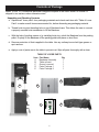
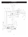
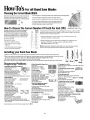
14” Professional Bandsaw
Owner’s Manual
Models: 10-350/10-350BAL
Record the serial number and date of purchase
in your manual for future reference.
Serial number:
Date of purchase:
For more information:
www.rikontools.com or [email protected]
For Parts or Questions:
Part #10-350M1
[email protected] or 877-884-5167
Operator Safety: Required Reading
IMPORTANT! Safety is the single most important consideration in the operation of this equipment. The following
instructions must be followed at all times.
There are certain applications for which this tool was designed. We strongly recommend that this tool not be modified and/
or used for any other application other than that for which it was designed. If you have any questions about its application,
do not use the tool until you have contacted us and we have advised you.
General Safety Warnings
KNOW YOUR POWER TOOL. Read the owner’s manual carefully. Learn the tool’s applications, work
capabilities, and its specific potential hazards.
ALWAYS GROUND ALL TOOLS.
If your tool is equipped with a three-pronged plug, you must plug it into a three-hole electric receptacle.
If you use an adapter to accommodate a two-pronged receptacle, you must attach the adapter plug to a
known ground. Never remove the third prong of the plug.
ALWAYS AVOID DANGEROUS ENVIRONMENTS.
Never use power tools in damp or wet locations. Keep your work area well lighted and clear of clutter.
ALWAYS REMOVE THE ADJUSTING KEYS AND WRENCHES FROM TOOLS AFTER USE.
Form the habit of checking to see that keys and adjusting wrenches are removed from the tool before
turning it on.
ALWAYS KEEP YOUR WORK AREA CLEAN. Cluttered areas and benches invite accidents.
ALWAYS KEEP VISITORS AWAY FROM RUNNING MACHINES.
All visitors should be kept a safe distance from the work area.
ALWAYS MAKE THE WORKSHOP CHILDPROOF.
Childproof with padlocks, master switches, or by removing starter keys.
NEVER OPERATE A TOOL WHILE UNDER THE INFLUENCE OF DRUGS,
MEDICATION, OR ALCOHOL.
ALWAYS WEAR PROPER APPAREL.
Never wear loose clothing or jewelry that might get caught in moving parts. Rubber-soled footwear is
recommended for the best footing.
ALWAYS USE SAFETY GLASSES AND WEAR HEARING PROTECTION.
Also use a face or dust mask if the cutting operation is dusty.
NEVER OVERREACH.
Keep your proper footing and balance at all times.
NEVER STAND ON TOOLS.
Serious injury could occur if the tool is tipped or if the cutting tool is accidentally
2
ALWAYS DISCONNECT TOOLS.
Disconnect tools before servicing and when changing accessories such as blades, bits, and cutters.
ALWAYS AVOID ACCIDENTAL STARTING.
Make sure switch is in “OFF” position before plugging in cord.
NEVER LEAVE TOOLS RUNNING UNATTENDED.
ALWAYS CHECK FOR DAMAGED PARTS.
Before initial or continual use of the tool, a guard or other part that is damaged should be checked to
assure that it will operate properly and perform its intended function. Check for alignment of moving
parts, binding of moving parts, breakage of parts, mounting, and any other conditions that may affect its
operation. A guard or other damaged parts should immediately be properly repaired or replaced.
Special Safety Rules For Bandsaws
1. Always allow the Bandaw blade to stop before removing scrap pieces from table.
2. Always keep hands and fingers away from the blade.
3. Never attempt to saw stock that does not have a flat surface, unless a suitable support is used.
4. Always hold material firmly and feed it into the blade at a moderate speed.
5. Always turn off the machine if the material is to be backed out of an uncompleted cut.
6. Adjust the upper guide about 1/8” above the material being cut.
7. Check for proper blade size and type for thickness and type of material being cut.
8. Make sure that the blade tension and blade tracking are properly adjusted.
9. Make “relief” cuts before cutting long curves.
10. Release blade tension when the saw will not be used for a long period of time.
California Proposition 65 Warning
WARNING: Some dust created by power sanding, sawing, grinding, drilling, and other construction activities contains
chemicals known to the State of California to cause cancer and birth defects or other reproductive harm.Your risk from
exposure to these chemicals varies, depending on how often you do this type of work. To reduce your exposure, work in
a well-ventilated area and with approved safety equipment, such as dust masks that are specially designed to filter out
microscopic particles.
For more detailed information about California Proposition 65 log onto rikontools.com.
Note:
This owner’s manual is not a teaching aid. Use of this owner’s manual is intended to
show assembly, adjustments, and general use.
SAVE THESE INSTRUCTIONS.
Refer to them often.
3
Table of Contents
Safety Warnings..................................................................................................................................................2 -3
Bandsaw Safety Rules ..........................................................................................................................3
Specifications ........................................................................................................................................4
Contents of Package ............................................................................................................................5
Loose Parts ...........................................................................................................................................6
Getting To Know Your Bandsaw ............................................................................................................7
Table Assembly .....................................................................................................................................8
Rip Fence Assembly .............................................................................................................................8
Hand-Wheel Assembly .........................................................................................................................8
Setting 90o Table Stop ...........................................................................................................................9
Tilting the Table .....................................................................................................................................9
Tracking Blade ......................................................................................................................................10
Adjusting Blade Tension .......................................................................................................................10
Blade Tension Indicator Adjustment.......................................................................................................10
Changing the Bandsaw Blade........................................................................................................11
Upper Blade Guide Adjustment ..........................................................................................................12
Lower Blade Guide Adjustment ..........................................................................................................12
Adjusting the Cutting Height ..................................................................................................................12
Changing Blade Speed .......................................................................................................................13
Setting Drive Belt Tension.......................................................................................................................13
Operation ............................................................................................................................................13-15
Electrical Requirements ..................................................................................................................................16
Maintenance................................................................................................................................... ..... 17
Wiring Diagram ...................................................................................................................................17
Troubleshooting .........................................................................................................................18-19
Changing Bandsaw Tire ..................................................................................................................................19
Adjusting Fence 90 Degrees to the Table..................................................................................................................19
Parts Diagrams/Lists ................................................................................................................................20-29
How To Guide .....................................................................................................................................30
Warranty .............................................................................................................................................31
Specifications
10-350
Throat Width
Max. Cutting Depth
Blade Length
Blade Width
Table Size
Table Tilt
Blade Speeds
Motor
Amps/Speed
Volts
Net weight
10-350BAL
13-9/16”
Throat
(345width
mm)
13-9/16” (345 mm)
13-15/16”
Max.(356
cutting
mm)
depth
13-15/16” (356 mm)
124” (3150
Blade mm)
length
124” (3150 mm)
1/4” –Blade
1”(6-25
width
mm)
1/4” – 1”(6-25 mm)
21-1/16”
Table
x 19-1/16”
size (535 mm x 485 mm) 21-1/16” x 19-1/16” (535 mm x 485 mm)
o
o
Left-10
Table
Right-45
tilt
Left-10o Right-45 o
2132 Blade
ft/min or
speeds
4101 ft/min
2163 ft/min or 4162 ft/min
2.5 HP
Motor
(RIKON)
3 HP (Baldor)
10A / Amps
1700 RPM
12.5A / 1725 RPM
220V Volts
230V
308 lbs
Net weight
315 lbs
4
Contents of Package
Model 10-350 14” Professional Bandsaw is shipped complete in one crate. Model 10-350BAL is
shipped in two cartons unless otherwise noted.
Unpacking and Checking Contents
a. Separate all “loose parts” from packaging materials and check each item with “Table of Loose
Parts” to make sure all items are accounted for, before discarding any packaging material.
b. Thread hoist ring into threading hole on top of Bandsaw frame. This allows the user to connect
a properly secured hoist mechanism to lift the Bandsaw.
c. With the help of another person or by installing hoist ring, unbolt the Bandsaw from the packing
pallet. Properly lift the Bandsaw off the packing pallet and place on level floor.
d. Remove protective oil that is applied to the table. Use any ordinary house hold type grease or
spot remover.
e. Apply a coat of paste wax to the table to prevent rust. Wipe all parts thoroughly with a clean
TABLE OF LOOSE PARTS
Item Part Name
Qty
A
Bandsaw Assembly
1
B Table w/insert
1
C Owner’s manual
1
D Parts Package 1
1
E Parts Package 2
1
D
B
14” Professional Bandsaw
Models: 10-350/10-350BAL
Owner’s Manual
A
C
Record the serial number and date of purchase
in your manual for future reference.
Serial number:
Date of purchase:
For more information:
www.rikontools.com or [email protected]
For Parts or Questions:
Part #10-350M1
[email protected] or 877-884-5167
5
E
Loose Parts List
LIST OF LOOSE PARTS
Table assembly:
A. Table
B. Table leveling bar and hardware
C. 90° table stop bolt
D. Table mounting bolts and washers
D
C
A
B
A
Rip fence assembly:
A. Fence bar
B. Fence
C. Fence carrier
D. Resaw bar
D
B
C
A
Tool holder assembly:
A. L wrench 2.5MM
B. L wrench 3MM
C. L wrench 4MM
D. L wrench 5MM
E. L wrench 6MM
F. 10mm wrench
G.13mm wrench
B
C
D
E
F
G
6
Getting to Know Your Bandsaw
A
F
G
P
B
H
Q
C
I
J
D
R
K
S
E
T
L
M
U
N
V
O
A. Hoist Ring
B. Tension Indicator Window
C. Blade Tension Hand-Wheel
D. Switch
E. Rip Fence
F. Guide Post Cap
G. Blade Tracking Window
H. Guide Post Rise/Fall Handle
I. Guide Post Lock Knob
J. Hinged Blade Guard
K. Blade Guides
L. Work Table
M. Drive Belt Tension Wheel
N. 4” Dust Ports
O. Foot Break
P. Blade Tracking Knob
Q. Quick Release Lever
R. Tool Holder
S. LED Light
T. Table Tilt & Lock Knobs
U. Power Control Box
V. Motor
7
Assembly
Blade Slot
Work Table Assembly
Installing Table Leveling Bar:
Locate the table leveling bar, two hex socket screws
and two washers (A-Fig.1 Inset).
Insert a hex socket screw and washer through the left
hole of the table leveling bar and into the threaded hole
on the left side of the blade slot (B-Fig.1). Make sure
that the opening of the slot on the right side of the table
leveling bar faces toward the table trunnion. This will
allow the table leveling bar to open outward from the
bandsaw.
Table Leveling Bar
B
Underside of Table
A
Figure 1
Rip Fence Assembly
With a 13mm wrench, remove one 13mm hex nut and
one washer from each stud on the fence bar (A-Fig.2).
Leave one each of 13mm hex nut and washer on each
stud on the fence bar. The remaining nut and washer
will be used for drift adjustments that will be described
later in this manual.
A
Figure 2
Next, install the fence bar studs into the table as
shown (Fig.3). Locate the 13mm hex nuts and washers
removed in Fig.10 and install on the opposite ends of
each fence bar stud. NOTE: It may be necessary to
open the table leveling bar to gain access to the right
side fence bar stud.
Hand Wheel Installation
A
There are two hand wheels used on the 10-350
bandsaw. The first controls the height of the upper guide
post, the second adds/removes tension on the drive
belt.
Figure 3
Attach the first hand wheel (Fig.4) to the rack and pinion
shaft on the upper part of the bandsaw, using the 5mm
“L” wrench provided.
Attach the second crank handle to the belt and speed
control rod located below the 4” dust port, using the
5mm “L” wrench provided.
8
Figure 4
Assembly
Adjustments
Storage for the “L” wrenches is provided for quick
access when adjustments are needed.
Tool Holder
Place the (4) “L” wrenches (3mm, 4mm, 5mm and 6mm)
in the tool holder on the rear column support (Fig.5).
Setting the Table Square to Saw Blade
The table may be set at 90° to the saw blade sides
by adjusting the table stop screw under the table. The
table stop screw rests on the top of the quick release
adjustment stop. By first loosening the locking nut
(A-Fig.6) and then adjusting the screw (B-Fig.6), the
table can be set correctly. Retighten the locking nut
(A-Fig.6) making sure that the setting is maintained.
The table may also be set at 90° to the back of the saw
blade by adjusting the four trunnion micro adjustment
screws (A-Fig.7). First, slightly loosen part #98 (refer to
parts explosion on page 18 of this manual). Using the
3mm “L” wrench, turn the rear trunnion micro adjusting
screws part #125. Turning the screws clockwise will
raise the trunnion; counterclockwise will lower. Check
table for 90° and tighten part #98.
(Trunnion has been removed from bandsaw for clarity. Micro
adjusting screws are raised to exaggerate location. Only two of the
four micro adjusting screws shown.)
Figure 5
A
B
Figure 6
A
Figure 7
Tilting the Table
Loosen the lock handle (A-Fig.8) on the table trunnion.
Turn the table tilting knob (B-Fig.8) to adjust the table to
the desired angle. Use the angle indicator scale on the
trunnion bracket to find the desired angle. Retighten the
lock handle to secure the table.
B
A
Figure 8
9
Adjustments
Tracking the Saw Blade
Warning! Unplug the bandsaw. Make sure the upper
and lower blade guides are adjusted away from the blade
and the tension scale is set to correspond to the width of
the blade you are using.
B
A
Note: The blade tension scale may read differently due to cut
specifications of the blade manufacturer. It might be necessary to
increase/decrease tension up/down one size on blade tension scale to
achieve proper blade tension.
Figure 9
Open both doors. Loosen the lock lever (A-Fig.9) by
turning it counter clockwise and turn the blade tracking
knob (B-Fig.9) clockwise/counterclockwise while turning
the upper wheel by hand at least three rotations until the
blade tracks centered on the wheel. Finally, tighten the lock
lever and close the doors.
Quick Release
Adjusting the Blade Tension
The 10-350 has a quick release blade function which
allows for fast blade changing and tensioning. The quick
release lever is shown in figure 10.
To loosen the tension of the blade, turn the blade tension
handwheel (A-Fig.11) counter clockwise. To tighten the
tension of the blade, turn the blade tension handwheel
clockwise.
Off
On
Figure 10
B
Tension the blade until the tension readings correspond
to the width of blade you are using by viewing through the
tension indicator window (B-Fig.11).
A
Note: The blade tension scale may read differently due to cut
specifications of the blade manufacturer. It might be necessary to
increase/decrease tension up/down one size on blade tension scale to
achieve proper blade tension.
Figure 11
Caution!
Always tension the blade with the quick
release lever in the “On” position. Failure to do so could
result in lack of blade tension or tension failure.
A
Blade Tension Indicator Adjustment
The blade tension indicator can be adjusted for
blades known to be cut over/under length by different
manufacturers. With moderate tension on the blade loosen
the two adjusting screws with a Phillips-head screw driver
(A-Fig.12). Adjust the blade indicator bracket up/down as
needed (B-Fig.12) and re-tighten the two adjusting screws.
10
B
Figure 12
Adjustments
Changing the Bandsaw Blade
A
Warning! Unplug the machine from the electrical
supply. This ensures that the Bandsaw will not
accidentally turn on if the ON/OFF switch is bumped.
a) Open the top and bottom wheel doors by turning
the door locking knobs. (A-Fig.13)
b) Release the blade tension by moving the quick
release lever (Fig.14) from right to left. Open the
hinged door on the blade guard by loosening the
wing screw (A-Fig.15). Loosen then open the
table leveling bar (A-Fig.16).
c) Remove the saw blade by feeding it through the
slot in the table (B-Fig.16), upper and lower blade
guides and the slot in the spine of the machine,
being careful not to cut yourself. Wear gloves for
protection.
d) When installing the new blade, ensure the blade
teeth are pointing downwards and towards you at
the position where the blade passes through the
table.
e) Center the blade on both wheels.
f ) Re-tension the new blade by moving the quick
release lever (Fig.14) left to right and check the
blade tracking. Spin the upper wheel clockwise
three times. The blade should run in the center of
both wheels. Refer to “Tracking the Saw Blade”
on page 10 for more details.
g) Set the blade guides as described in the section
“Adjusting the Blade Guides” on page 12.
h) Close the hinged door on the blade guard
and tighten the wing screw (A-Fig.15). Close the
table leveling bar and tighten (A-Fig. 16).
i) Close and lock both the wheel doors (A-Fig.14)
before reconnecting the power supply.
Figure 13
A
Quick Release
On
Off
Off
On
Figure 14
A
Hinged Door
Figure 15
B
A
Figure 16
11
Adjusting the Blade Guides
A
Upper Guides: To adjust the upper blade guides,
first position the roller guides relative to the blade by
loosening the Allen cap head screw (A-Fig.17) and
sliding the guide assembly until the side roller guides
are approximately 1/16” behind the gullet of the blade
then tighten the Allen cap head screw (A-Fig.17).
Next set the roller guides to within 1/32” of the blade
by releasing the lock knob (B-Fig.17) and turning
the micro-adjusting knob (C-Fig.17). Do not set the
guides too close, as this will adversely affect the life
of the blade. When the correct adjustment is reached,
lock the guides in position by tightening the lock knob
(B-Fig.17). Finally, follow the same steps above to
position the rear thrust roller guide.
Lower Guides: To adjust the lower blade guides, first
loosen the hex nut (A-Fig.18) then move the lower
guide support casting to allow the side roller guides to
be approximately 1/16” behind the gullets of the blade
and tighten the hex nut (A-Fig.18). Next set the roller
guides to within 1/32” of the blade by releasing the lock
knob (B-Fig.18) and turning the micro-adjusting knob
(C-Fig.18). Do not set the guides too close, as this will
adversely affect the life of the blade. When the correct
adjustment is reached, lock the guides in position by
tightening the lock knob (B-Fig.18). Adjust the thrust
bearing to be just clear of the back of the blade by
unlocking the hex nut (D-Fig.18), and turning adjusting
knob on rear of the trunnion. Finally, tighten hex nut
(D-Fig.18).
Make sure doors are closed, turn the bandsaw on and
inspect that the upper, lower and thrust bearings are
not turning. All bearings should not turn unless pressure
from workpiece is applied to the blade. If bearings are
turning under no pressure, repeat steps to adjust the
blade guides.
B
C
Figure 17
D
B
A
C
Figure 18
B
A
Figure 19
Adjusting the Cutting Height
Loosen the guidepost lock knob (A-Fig.19) and turn the
guidepost handwheel (B-Fig.19) to raise or lower the
guide post/upper blade guide assembly to the desired
height. Then tighten the guidepost lock knob.
Note: The bottom edge of the guide bearings should
be approximately 1/4”above the top surface of the work
piece. (Fig.20)
12
Approximately
1/4”
Figure 20
Changing Blade Speed Pulley Setting
Warning! Before changing the speed, always
make sure the machine has been unplugged from the
electrical supply.
A
The 10-350 has two pulley speed ranges, low speed
(2132 ft/min) and high speed (4101 ft/min).
The 10-350BAL has two pulley speed ranges, low
speed (2163 ft/min) and high speed (4162 ft/min).
The lower wheel (A-Fig.21) and the motor shaft have
twin multi-vee pulleys (B-Fig.21). A flat ribbed “J” belt
(C-Fig.21) passes around the wheel pulley, motor pulley
and belt tension pulley. The belt tension is released and
applied by using the handwheel (D-Fig.21).
C
B
Tension Pulley
For the high speed the belt should be fitted to the rear
pulley on both the motor and the wheel (A-Fig.22).
D
Figure 21
For the low speed the belt should be fitted to the front
pulley on both the motor and wheel (B-Fig.22).
Setting Drive Belt Tension
A
To properly adjust belt tension, turn hand-wheel
(D-Fig.21) until there is 1/2” deflection in the flat ribbed
“J” belt.
B
Operation
Switch Control Station
Figure 22
The 10-350 has a key-on safety feature that will lock
out unauthorized users such as students, coworkers or
employees not trained or qualified to use the bandsaw.
To operate the saw turn the key (A-Fig.23) to the right to
activate the control station. A green light will illuminate
(B-Fig.23) showing that the saw is ready for use. Press
the green “START” button (C-Fig.23) to turn the saw on.
Once the cut is finished press the “STOP” button to turn
the saw off.
A
B
C
D
Note: If working with large pieces and not able to reach the “STOP”
button simply press the foot brake. There is a switch built into the
foot break assembly that will turn the saw off.
Figure 23
13
Adjusting the Rip Fence/Drift
Align the fence assembly in or out until parallel with the
side of the blade by turning the adjustment collars and
the fence bolts accordingly (A-Fig.24). If the mounting
bolts have been tightened, these will need loosened
off before this adjustment can be made. The same
adjustment can be made to compensate for blade drift.
A
Check that the fence is 90 degrees to the table using
a suitable square. If no adjustments are needed fully
tighten the fence bar nuts. If adjustment is required, raise
or lower either side of the fence rail until the fence body
is 90 degree to the table. Once set at 90 degrees, fully
tighten the fence bar nuts.
Re-sawing
A resaw guide is supplied with this bandsaw to help
correct any blade wandering during certain resawing
operations.
Figure 24
For resawing, attach the resaw bar to the slot on the
fence. Position the resaw bar so that it is aligned with
the front of the blade. Draw a reference line down the
workpiece. Use the bar as a pivot point and follow the
line through the cut. (Fig.25)
Note: The resaw bar is not needed for all resaw operations. Proper
blade tension and selection as well as proper guide set up will allow
resawing flat stock against the fence.
Pivot Workpiece
Basic Operation
Figure 25
The blade cuts on a continuous down-stroke.
With both hands, firmly hold the workpiece down on the table, and feed it towards the blade slowly,
keeping your hands away from the blade.
For best results the blade must be sharp. A dull blade will not cut correctly, especially when straight
cutting, and causes excess pressure to be applied on the rear guide bearings.
Select the right blade for the job, depending on the thickness of the wood and the cut to be made.
The thinner and harder the wood, the finer the teeth of the blade should be. Use a fine tooth blade for
cutting sharp curves.
The machine is especially suited for cutting curves, but will also make straight cuts. When cutting,
follow the design marked out by pushing and turning the workpiece evenly.
Do not attempt to turn workpiece without pushing it as this may cause the workpiece to get stuck, or
the blade to bend.
14
Features and Safety
The 10-350 14” Professional Bandsaw has many builtin safety and feature items shown below.
LED Work Light
The LED work light is built onto a long flexible goose
neck giving it the ability to illuminate the work surface
on both sides of the blade. To operate the LED work
light depress the round button (A-Fig.26). LED lights
are very bright and can wash out reference lines on
a workpiece. If the light is too bright, move the goose
neck away reducing the amount of light cast on the
workpiece.
Foot Brake
The foot brake, when depressed will slow the blade
to a stop. The foot brake (A-Fig.27) on the 10-350
will also shut off the bandsaw simultaneously. This
is an added safety feature that allows you to handle
large workpieces without having to reach back to the
switch control station to the main “STOP” button. The
lever, when depressed pivots the break pad (B-Fig.27)
against the break disc (C-Fig.27) on the motor pulley.
Quick Release Blade Tension Lever
The tension lever that operates the quick release blade
function has two of the most innovative features on
the 10-350. One feature allows the blade tension to
be released from back or front of the saw. The other
feature disables the saw from operating if the quick
release lever is not engaged with no tension on the
blade. This prevents accidental starting while the
tension lever is off and will eliminate the possibility of
damaging a blade or the saw. Fig.28
Dual Door Safety Switches
Both the upper and lower blade wheel doors are
equipped with safety switches that will shut the saw off
when opened. The saw will not operate until the blade
wheel doors are closed. If a door is opened while the
saw is running power to the motor will be cut off. The
only way to restart the saw is to make sure both band
wheel doors are closed before pressing the “START”
button.
15
A
Figure 26
C
B
A
Figure 27
Operate Quick Release from
the Front or Back of the Saw
Figure 28
Electrical Requirements
In the event of a malfunction or breakdown, grounding provides a path of least resistance for electric
current to reduce the risk of electric shock. This tool is equipped with an electric cord having an
equipment-grounding conductor and a grounding plug. The plug must be plugged into a matching
outlet that is properly installed and grounded in accordance with all local codes and ordinances.
Do not modify the plug provided. If it will not fit the outlet, have the proper outlet installed by a
qualified electrician.
Improper connection of the equipment-grounding conductor can result in a risk of electric shock. The
conductor, with insulation having an outer surface that is green with or without yellow stripes, is the
equipment-grounding conductor. If repair or replacement of the electric cord or plug is necessary, do
not connect the equipment-grounding conductor to a live terminal.
Check with a qualified electrician or service personnel if the grounding instructions are not completely
understood, or if in doubt as to whether the tool is properly grounded.
Use only three wire extension cords that have three-prong grounding plugs and three-pole
receptacles that accept the tool’s plug.*
Repair or replace a damaged or worn cord immediately.
This tool is intended for use on a circuit that has an outlet that looks the one illustrated in Figure
A below. The tool has a grounding plug that looks like the grounding plug as illustrated in Figure A
below.
* Canadian electrical codes require extension cords to be certified SJT type or better.
** Use of an adapter in Canada is not acceptable.
Figure A
16
Maintenance
Caution! BEFORE CLEANING OR CARRYING OUT MAINTENANCE WORK, DISCONNECT
THE MACHINE FROM THE POWER SOURCE (WALL SOCKET). NEVER USE WATER OR OTHER
LIQUIDS TO CLEAN THE MACHINE. USE A BENCH BRUSH. DO NOT USE COMPRESSED
AIR NEAR BEARINGS. REGULAR MAINTENANCE OF THE MACHINE WILL PREVENT
UNNECESSARY PROBLEMS.
Keep the table clean to ensure accurate cutting.
Keep the outside of the machine clean to ensure accurate operation of all moving parts and prevent
excessive wear.
Keep the ventilation slots of the motor clean to prevent it from overheating.
Keep the inside (near the saw blade, etc.) clean to prevent accumulation of dust.
Wiring Diagram
WARNING!
This machine must be grounded. Replacement of the power supply cable should only be
done by a qualified electrician.
17
Troubleshooting
WARNING!
FOR YOUR OWN SAFETY, ALWAYS TURN OFF AND UNPLUG THE MACHINE BEFORE CARRYING OUT ANY
TROUBLESHOOTING.
TROUBLE
PROBABLE CAUSE
REMEDY
The machine does not
1. No power supply.
work when switched on. 2. Defective switch.
Check the cable for breakage.
Contact your local dealer for repair.
The blade does not
move with the motor
running.
1. The quick release lever or
blade tension handwheel has
not been tightened.
2. The blade has come off one
of the wheels.
3. The saw blade has broken.
4. The drive belt has snapped.
Switch off the motor, tighten the quick release
lever or blade tension handwheel.
1. Fence for cutting not used.
2. Too fast feed rate.
Use a fence.
Put light pressure on the workpiece & make
sure the blade does not bend.
Use a new blade.
The blade does not cut
in a straight line.
The blade does not cut,
or cuts very slowly.
3. The blade teeth are dull or
damaged.
4. Blade guides not suitably
adjusted.
1. The teeth are dull, caused by
cutting hard material or long
use.
2. The blade was mounted in
the wrong direction.
Sawdust builds up
inside the machine.
Sawdust inside the
motor housing.
The machine does not
cut at 45o or 90o angles.
The blade cannot be
properly positioned on
the bandwheels.
Open the hinged door and check.
Replace the blade.
Replace the belt.
Adjust the blade guides (see the section on
page 12).
Replace the blade, use a 6 T.P.I. blade for
wood and soft materials. Use a 14 T.P.I.
blade for harder materials. A 14 T.P.I. blade
always cuts slower due to the finer teeth and
the slower cutting performance.
Fit the blade correctly.
1. This is normal
Clean the machine regularly. Open the
hinged door and remove the sawdust with a
vacuum cleaner.
1. Excessive dust build-up
on the machine exterior
components.
Clean the ventilating slots of the motor with
a vacuum cleaner. From time to time remove
the sawdust to prevent it from being sucked
into the housing
1. The table is not at right
angles to the blade.
2. The blade is dull or too much
pressure was put on the
workpiece.
Adjust the table.
1. The wheels are not in
alignment. Defective bearing.
2. The blade tracking knob
hasn’t been properly adjusted.
3. Inferior blade.
Contact Technical Support @ 877-884-5167
or [email protected].
Adjust the knob (see the section on page 10).
Replace the blade or put less pressure on
the workpiece.
Replace the blade.
For parts or technical questions contact: [email protected] or 877-884-5167.
18
Troubleshooting
Adjusting the Upper Blade Guide Bearings Parallel to the Blade
(Refer to “Guide Post Assembly” parts diagram on page 28)
This step may not be necessary, it is factory preset. If adjustment is needed follow the steps
below.
First slightly loosen part #226 Hex Bolt M8X20 (4 each) on rear of upper bandsaw housing. This
will allow you to adjust the micro adjustment screws #227 in part #224 Gear Bracket.
Next place a 3mm “L” wrench through the sight holes in part #198 Cover. Turning clockwise on
the micro adjustment screws in left two holes will adjust the left bearings to the right. Turning
clockwise on the micro adjustment screws in the right two holes will adjust the right bearings to
the left. Check bearings for parallel.
Lastly tighten parts #226 Hex Bolt (4) on back of bandsaw housing. Repeat steps if the bearings
are still not parallel.
Adjust Upper Side Bearings Which Will Not Track Close to the Blade
(Refer to “Guide Post Assembly” parts diagram on page 28)
If the right or left upper guide bearings do not adjust to within 1/32” of the blade, the Guide Post
(part #195) may need adjustment.
First lower the Guide Post (part #195) all the way to the table.
Second slightly loosen parts #226 Hex Bolt M8X20 (4) on the back of the upper bandsaw cabinet
housing.
Next swing the Guide Post (part #195) right or left until side guide bearings are properly spaced
on each side of blade making sure that the blade will strike the center of the rear thrust bearing.
Tighten part #226 Hex Bolt M8X20 (4) on the back of the upper bandsaw cabinet housing.
Raise the Guide Post (part #195) seven inches off the table and check alignment. If side guide
bearings travel out of alignment repeat steps above. Raise the Guide Post (part #195) to the top
of the travel and check final alignment. Repeat steps above if necessary.
Changing Bandsaw Tire
Use a putty knife to get underneath the tire and pull it up and away from the wheel. Work the putty
knife all the way around the wheel to loosen the tire. Then, use the putty knife as leverage to flip the
tire over and off of the wheel. Clean the inside of the groove, removing any dirt, debris or cement with
lacquer thinner.
Soak the replacement tire in warm water to make it more flexible. Let tire dry and lay on top of wheel.
Start by setting the tire into the wheel groove at the top of the wheel. Using a putty knife, work the
new tire around the wheel, making sure not to slice the tire. If rubber cement is to be used, make sure
to distribute evenly. Having high spots between the wheel and the tire will cause a vibration and effect
blade tracking.
19
Parts Diagram
Frame Assembly
20
Parts List
Frame Assembly
Key No.
1
2
3
4
5
6
7
8
9
10
11
12
13
14
15
16
17
18
19
20
21
22
23
24
25
26
27
28
29
30
31
32
33
34
35
36
37
38
39
40
41
42
43
44
45
46
47
48
Part No.
M8X16GB825Z
ST3D5X19GB845Z
WSH4GB96Z
JL20073003
KW3-0Z-2B
JL20073002
JMBS1402011000
RVT4X8GB12618
JL22010008
RVT3X7GB12618A
JL26010001
JMBS1402012000
M6GB889Z
JL26010007
M6X25GB70Z
hy57b
LA39
LA42Y2-10/B
M4X10GB818Z
JMBS1402010003
PL3
JL27010005
M5X10GB818Z
JMBS1402010001
WSH5GB97D1Z
JL26010010
JMBS1402013000
M4X30GB818Z
QKS7-01
M6X16GB70Z
WSH6GB97D1Z
JMBS1402010002
M8GB6170Z
M6X30GB70Z
M6GB6170Z
FDPT1202020021
M8X16GB70Z
M6X20GB70Z
WSH6GB93Z
WSH6GB97D1Z
JXBS2401015101
JMBS1402015001
JMBS1402015100
M10GB889Z
WSH10GB97D1Z
JL26010006
JXBS2401015005
JL26010013
Description
Ring
Tap screw
Washer
Micro-switch cap
Switch
Micro-switch cover
Frame
Rivet
Leaf spring
Rivet
Clear window
Upper door assm.
Locking nut
Tube
Hex socket screw M6X25
Stop switch box
Button
Key switch
Pan head screw
Switch plate
Stop switch
Pointer plate
Pan head screw
Pointer
Flat washer
Pointer screw
Lower door assm.
Pan head screw
Microswitch
Hex socket screw M6X16
Flat washer
Micro-switch plate
Nut
Hex socket screw M6X30
Nut
Spring
Hex socket screw M8X16
Hex socket screw M6X20
Spring washer
Flat washer
Pedal
Lever
Brake block
Locking nut
Flat washer
Knob
Side cover
Plate
Key No.
49
50
51
52
53
54
55
56
57
58
59
60
61
62
63
64
65
66
67
68
69A
69B
70
71
72
73
74
75
76
77
78
79
80
81
82
83
84
85
86
87
88
89
90
91
92
93
94
21
Part No.
WSH6GB96Z
M6X16GB5783Z
M6GB889Z
M6X25GB5783Z
JL26010003
WSH6GB96Z
M6GB6170Z
M8GB889Z
JL26010014
JL26010015
JMBS1402020002
JMBS1402020003
M8X10GB80B
JL26020012
JL20010015
M5X8GB78Z
JMBS1402023003
M8X20GB5783Z
WSH8GB97D1Z
WSH8GB862D2Z
H8022684-01
35LYY983
M8X25GB5783Z
M8GB6170Z
JMBS1402020004
CLP17GB894D1B
BRG80101GB278
JMBS1402023002
JMBS1402023001
CLP28GB893D1B
CLP12GB894D1B
WSH27GB93B
M27X2GB6171Z
JL48091100
1905010A
QSK-02
M4X30GB819Z
JMBS1402070000
M4X15GB819B
JL60010004
JMBS1402010005
JL26030016
JL26030015
JMBS1402010004
M5X10GB70Z
M4GB6170Z
JL26020014
Description
Washer
Bolt M6X16
Locking nut
Hex bolt M6X25
Brush
Washer
Hex nut M6
Locking nut M8
Seat pad
Screw shaft
Drive belt
Motor pulley
Hex screw M8X10
Small handwheel
Retaing ring
Screw M5X8
Thread rod
Hex screw M8X20
Flat washer
Washer
2.5HP RIKON Motor
3HP Baldor Motor
Hex screw M8X25
Hex nut M8
Lower bearing bolt
Retaining ring
Bearing
Sliding shaft
Tension wheel
Retaing ring
Retaing ring
Spring washer
Nut M27X2
Relay
Bushing
Microswitch
Screw M4X30
Light
Screw M4X15
Bushing
Upper guide cover
Thread handle
Adjusting Knob
Indicator light
Hex socket screw M5X10
Nut M4
Small handwheel
Parts Diagram
Wheel Assembly
22
Parts List
Wheel Assembly
Key No.
95
96
97
98
99
100
101
102
103
Part No.
WSH8GB96Z
M8X16GB70Z
JMBS1402020001
JMBS1402022100
JL28020004
JL21022002A
CLP40GB893D1B
BRG180203GB278
JL28022001
Description
Washer
Hex socket screw M8X16
Blade
Lower wheel assm.
Bushing
Tire
Retaining ring
Bearing
Upper wheel
23
Parts Diagram
Table & Fence Assembly
24
Parts List
Table & Fence Assembly
Key No.
104
105
106
107
108
109
110
111
112
113
114
115
116
117
118
119
120
121
122
123
124
125
126
127
128
129
130
131
132
Part No.
JMBS1602060001
JMBS1601060002
WSH6GB97D1Z
WSH6GB93Z
M6X16GB70Z
JL20024001
JL20024002
JMBS1601060003
JL28060010
JMBS1602060002
JL28060005A
WSH8GB97D1Z
WSH8GB93Z
M8GB6170Z
JL27050009
WSH8GB96Z
JL20030003
M8X25GB70Z
JL26041006
BRG6201GB276
WSH8GB97D1Z
JL26052001
M6GB6172Z
M6GB41Z
JL26052002
M12X90GB801Z
M5X10GB70Z
M5X50GB70Z
M10GB889Z
Description
Key No.
Rip fence
Locking Plate
Washer
Spring washer
Hex socket screw M6X16
Adjusting Knob cap
Adjusting Knob body
Knob seat
Clip
Fence rail
Support shaft
Washer
Spring washer
Hex nut M8
Support plate
Washer
Wing knob
Hex socket screw M8X25
Bearing bushing
Bearing
Washer
Support rod
Nut M6
Nut M6
Adjusting handle
Carriage bolt M12x90
Hex socket screw M5X10
Hex socket screw M5X50
Locking nut
133
134
135
136
137
138
139
140
141
142
143
144
145
146
147
148
149
150
151
152
153
154
155
156
157
158
159
160
161
25
Part No.
WSH10GB97D1Z
M12X30GB5781B
WSH12GB97D1B
WSH12GB93B
JL26050002B
JL26055000
FDPT1202040015
M6X10GB70Z
WSH6GB96Z
JL26050011
JL26050005A
ST2D9X6D5GB845Z
JMBS1402016001
JMBS1402051009
CLP6GB896B
JMBS1402051004
JMBS1402051005
JMBS1402051003
CLP12GB894D1B
BRG6001-2RSGB276
JMBS1402051006
M6X30GB70Z
JL26050004C
M8X20GB5783Z
WSH8GB97D1Z
M8GB6170Z
M8X50GB5783Z
JMBS1602030001
JL26050008
Description
Washer
Screw M12X30
Washer
Spring washer
Lower table trunnion
Gear
Locking handle
Hex socket screw M6X10
Washer
Guide shaft
Pointer
Pan head screw
Lower guide body
Washer
Ring
Tube
Threaded shaft
Lock plate
Retaining ring
Bearing
Bushing
Hex socket screw M6X30
Upper table trunnion
Hex screw
Washer
Nut M8
Bolt M8X50
Table
Table insert
Parts Diagram
Blade Tension/Tracking
26
Parts List
Blade Tension/Tracking
Key No.
164
165
166
167
168
169
170
171
172
173
174
175
176
177
178
179
180
181
182
183
184
185
186
187
188
189
190
191
192
193
194
Part No.
Description
M10GB6170Z
WSH10GB93B
M12GB923Z
WSH12GB93B
M10GB889Z
WSH10GB97D1Z
JXBS1801030006
JXBS1801030007
JXBS1401030002
JMBS1402040011
JMBS1402040010
JMBS1402040001
M5X10GB70Z
PIN3X30GB879D1B
JMBS1402040012
JMBS1402040009
BRG51102GB301
JMBS1402040005
JMBS1402040006
BRG51105GB301
JMBS1402040007
M10X30GB70Z
JMBS1402040008
JMBS1402040003
JMBS1402040004
JXBS2201023004
WSH20GB95Z
WSH40GB1972A
WSH12GB96Z
M6X12GB80B
M10GB6170Z
Hex nut M10
Spring washer
Nut M12
Spring washer
Locking nut
Flat washer
Bolt
Threaded rod
Slide rod
Upper wheel shaft
Bushing
Switch plate
Hex socket screw M5X10
Roll pin
Threaded plate
Threaded rod
Bearing
Upper block
Lower block
Bearing
Support plate
Hex socket screw M10X30
Knob bushing
Knob lever
Knob
Small handwheel
Flat washer
Spring
Washer
Hex screw M6X12
Nut M10
27
Parts Diagram
Guide Post Assembly
28
Parts List
Guide Post Assembly
Key No.
195
196
197
198
199
200
201
202
203
204
205
206
207
208
209
210
211
212
213
214
215
216
217
218
219
220
221
222
223
224
225
226
227
228
229
230
231
232
233
234
235
236
237
238
239
240
241
Part No.
Description
JMBS1402050001
JMBS1402050002
M4X10GB819Z
JL26040002
M8X10GB70Z
JMBS1402052000
JL26040006
1501006
M4X8GB818Z
JL26042011
M4GB6170Z
M6X30GB70Z
JMBS1402051006
CLP12GB894D1B
BRG6001-2RSGB276
JMBS1402051001
CLP6GB896B
JMBS1402051004
JMBS1402051005
JMBS1402051003
JMBS1402051009
JMBS1402051008
JMBS1402051007
JMBS1402051002
M6X20GB70Z
M8X12GB70Z
WSH5GB96Z
M5X10GB70Z
M5X10GB818Z
JL26040008
WSH8GB96Z
M8X20GB5783Z
M6X12GB77B
JL2603012
1501009-2
M6X12GB80B
M5X8GB78B
CLP12GBGB884
JL26040003
JL26040004
JL26040015
JL26040007
M5X10GB818Z
M6X15GB17880D3Z
WSH6GB96Z
JXBS2401054001
JL26041005
Guide post
Rack
Pan head screw
Cover
Hex socket screw M8X10
Blade cover
Screw
Gear
Pan head screw
Spectator
Hex nut M4
Hex socket screw M6X30
Bushing
Retaining ring
Bearing
Upper guide body
Ring
Threaded bushing
Threaded shaft
Lock plate
Washer
Threaded shaft
Threaded bushing
Bushing
Hex socket screw M6X20
Hex socket screw M8X12
Washer
Hex socket screw M5X10
Pan head screw
Gear bracket
Washer
Hex bolt M8X20
Screw M6x12
Big handwheel
Handle assm.
Hex screw M6X12
Hex screw M5X8
Ring
Bushing
Rod
Locking handle
Setting plate
Pan head screw
Nut M6X15
Washer
Wing knob
Support bracket
29
30
Warranty
5-Year Limited Warranty
RIKON Power Tools Inc. (“Seller”) warrants to only the original retail consumer/purchaser of our
products that each product be free from defects in materials and workmanship for a period of five
(5) years from the date the product was purchased at retail. This warranty may not be transferred.
This warranty does not apply to defects due directly or indirectly to misuse, abuse, negligence,
accidents, repairs, alterations, lack of maintenance or normal wear and tear. Under no
circumstances will Seller be liable for incidental or consequential damages resulting from
defective products. All other warranties, expressed or implied, whether of merchantability,
fitness for purpose, or otherwise are expressly disclaimed by Seller. This warranty does not cover
products used for commercial, industrial or educational purposes.
This limited warranty does not apply to accessory items such as blades, drill bits, sanding discs or
belts and other related items.
Seller shall in no event be liable for death, injuries to persons or property, or for incidental,
contingent, special, or consequential damages arising from the use of our products.
To take advantage of this warranty proof of purchase documentation, which includes date of
purchase and an explanation of the complaint, must be provided.
The Seller reserves the right to effect at any time, without prior notice, those alterations to parts,
fittings, and accessory equipment which they may deem necessary for any reason whatsoever.
To take advantage of this warranty, please fill out the enclosed warranty card and send it to:
RIKON Warranty
16 Progress Rd.
Billerica, MA 01821
The card must be entirely completed in order for it to be valid. If you have any questions
please contact us at 877-884-5167 or [email protected].
31
For more information:
16 Progress Rd
Billerica, MA 01821
877-884-5167/978-528-5380
[email protected]
www.rikontools.com
Copyright RIKON Power Tools Inc. 2012
Printed in China 3/12