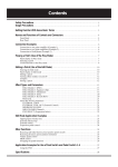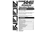
1
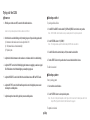
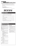
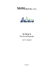
ZOOM STUDIO
Operation Manual
PEAK
POWER
MIDI CONTROL
512 PROGRAMS
VOCODER, ROTARY
MIC IN
INPUT
OUTPUT
16
15
14
13
12
11
10
9
Reverse SFX
Power Pit/Echo
Gate Flg/Echo
Echo Cho/Echo
Dly Tim/Rev
Solo Pit/Rev
Drums Flg/Rev
Percus Cho/Rev
Hall Chourus 1
16
Room Flanger 2
15
Plate Pitch 3
Vocal Tremolo 4
14
Ambi Dly+Rev 5
13
Orche Cho+Rev 6 A B 12
11
Studio Flg+Rev 7
10
Session Pit+Rev 8
9
EFFECTS
BANK
2
3
4
5
6
7
8
PATTERN
MANUAL
ZOOM STUDIO
(Demo)1
MEMORY
STORE
REV
MOD CANCEL
SERI
2
1
EDIT
LOW
HIGH
EQ
DRY
PARA
WET
BANK
MIX
EFFECT
A/ B
EDIT
SFX
MIDI
Thank you for selecting the ZOOM STUDIO 1204 (hereafter simply called the "1204").
Major Features
Organization of This Manual
The 1204 is a multi-effect device with the following features:
This manual consists of the following chapters.
• The Basics: This chapter lists the names of controls and parts, and describes how to connect and set up the
1204.
• Operation: This chapter explains how to use the 1204.
• Effect Types, Effect Patterns, Effect Parameters: This chapter describes the various effect types, effect
patterns, and effect parameters.
• Important Information: This chapter contains troubleshooting steps and safety precautions.
• 512 preset effect programs (32 effects x 16 patterns)
Memory capacity for storing up to 100 of your own effect settings, resulting in a total of 612 available
effect sounds.
• Easily changeable parameters let you create your own effect settings.
• Manual mode allows editing parameters in real time while using an effect.
Memory mode lets the user instantly choose any of 100 stored effects.
■ When using the 1204 for the first time
(1) First read the section "Safety Precautions" in the chapter "Important Information."
(2) Refer to the chapter "The Basics" to connect and set up your 1204.
(3) Refer to the chapter "Operation" to try out the various effects.
(4) When wishing to edit effects to create your own sound, refer to the chapter "Effect Types, Effect Patterns,
Effect Parameters."
• Control by external MIDI equipment possible.
• Integrated 18-bit A/D and D/A converter with sampling frequency of 44.1 kHz achieves professional
sound quality at an astonishingly affordable price.
■ In case of trouble
If the 1204 does not seem to function correctly, please refer to the section "Troubleshooting" in the chapter
"Important Information."
Please take the time to read this manual carefully so as to get the most out of your 1204 and to ensure optimum performance and reliability.
Retain this manual, the warranty card and all other documentation for future reference.
■1■
CONTENTS
THE BASICS
••••••••••••••••••••••••••••••••••••••••••••••••••••••••••••••••••••••••••••••••••••••••••••••••
••••••••••••••••••••••••••••••••••••••••••••••••••••••••••••••••••••••••••••••••••••••••••••••
12
Operation States ••••••••••••••••••••••••••••••••••••••••••••••••••••••••••••••••••••••••••••••••••••
Modes •••••••••••••••••••••••••••••••••••••••••••••••••••••••••••••••••••••••••••••••••••••
Functions ••••••••••••••••••••••••••••••••••••••••••••••••••••••••••••••••••••••••••••••••••
Mode Selection •••••••••••••••••••••••••••••••••••••••••••••••••••••••••••••••••••••••••••••••••••••
Manual mode ••••••••••••••••••••••••••••••••••••••••••••••••••••••••••••••••••••••••••••••
Memory mode •••••••••••••••••••••••••••••••••••••••••••••••••••••••••••••••••••••••••••••
Recall mode •••••••••••••••••••••••••••••••••••••••••••••••••••••••••••••••••••••••••••••••
Functions •••••••••••••••••••••••••••••••••••••••••••••••••••••••••••••••••••••••••••••••••••••••••••
Store function •••••••••••••••••••••••••••••••••••••••••••••••••••••••••••••••••••••••••••••
Effect on/off function •••••••••••••••••••••••••••••••••••••••••••••••••••••••••••••••••••••
MIDI channel setting function ••••••••••••••••••••••••••••••••••••••••••••••••••••••••••••
Trying out the 1204 ••••••••••••••••••••••••••••••••••••••••••••••••••••••••••••••••••••••••••••••••
Power-on ••••••••••••••••••••••••••••••••••••••••••••••••••••••••••••••••••••••••••••••••••
Selecting an effect •••••••••••••••••••••••••••••••••••••••••••••••••••••••••••••••••••••••••
Selecting a pattern •••••••••••••••••••••••••••••••••••••••••••••••••••••••••••••••••••••••••
Adjusting an effect ••••••••••••••••••••••••••••••••••••••••••••••••••••••••••••••••••••••••
Turning effect processing on and off ••••••••••••••••••••••••••••••••••••••••••••••••••••••
Storing effect settings in memory •••••••••••••••••••••••••••••••••••••••••••••••••••••••••
Switching between manual mode and memory mode ••••••••••••••••••••••••••••••••••••
Calling up stored effect settings •••••••••••••••••••••••••••••••••••••••••••••••••••••••••••
Editing a stored setting ••••••••••••••••••••••••••••••••••••••••••••••••••••••••••••••••••••
MIDI control •••••••••••••••••••••••••••••••••••••••••••••••••••••••••••••••••••••••••••••••••••••••
MIDI channel setting function ••••••••••••••••••••••••••••••••••••••••••••••••••••••••••••
Using MIDI to call up stored effect settings ••••••••••••••••••••••••••••••••••••••••••••••
Using MIDI to change effect parameters •••••••••••••••••••••••••••••••••••••••••••••••••
Recalling Factory Default Memory Settings •••••••••••••••••••••••••••••••••••••••••••••••••••••
13
13
13
14
14
14
14
15
15
15
15
16
16
16
16
17
17
18
19
19
20
21
21
21
22
22
OPERATION
Major Features ••••••••••••••••••••••••••••••••••••••••••••••••••••••••••••••••••••••••••••••••••••••• 1
Organization of This Manual ••••••••••••••••••••••••••••••••••••••••••••••••••••••••••••••••••••••• 1
Safety Precautions ••••••••••••••••••••••••••••••••••••••••••••••••••••••••••••••••••••••••••••••••••• 4
6
Controls and Functions •••••••••••••••••••••••••••••••••••••••••••••••••••••••••••••••••••••••••••••• 7
Front Panel •••••••••••••••••••••••••••••••••••••••••••••••••••••••••••••••••••••••••••••••••• 6
Rear Panel ••••••••••••••••••••••••••••••••••••••••••••••••••••••••••••••••••••••••••••••••••• 7
Connections •••••••••••••••••••••••••••••••••••••••••••••••••••••••••••••••••••••••••••••••••••••••••• 8
Connection between electronic instrument and playback equipment ••••••••••••••••••••• 10
Connection to send/return jacks of a mixe •••••••••••••••••••••••••••••••••••••••••••••••• 10
Connection between microphone and playback equipment ••••••••••••••••••••••••••••••• 10
Using two effects in parallel ••••••••••••••••••••••••••••••••••••••••••••••••••••••••••••••• 10
Rack Mount ••••••••••••••••••••••••••••••••••••••••••••••••••••••••••••••••••••••••••••••••••••••••• 11
■2■
•••••••••••••••••••••••••••
24
•••••••••••••••••••••••••••••••••••••••••••••••••••••••••••••••••••
25
EFFECT TYPES, EFFECTPATTERNS, EFFECT PARAMETERS
Category: REV (Reverb)
••••••••••••••••••••••••••••••••••••••••••••••••••••••••••••
Category: PARA (Parallel)
26
CHORUS
FLANGER
PITCH
TREMOLO
•••••••••••••••••••••••••••••••••••••••••••••••••••••••••••••••••••
27
DLY+REV
CHO+REV
FLG+REV
PIT+REV
••••••••••••••••••••••••••••••••••••••••••••••••••••••••••••••••
Category: SFX (Special Effects)
27
CHO / REV
FLG / REV
PIT / REV
TRM / REV
CHO / ECHO
FLG / ECHO
PIT / ECHO
••••••••••••••••••••••••••••••••••••••••••••••••••••••••••
••••••••••••••••••••••••••••••••••••••••••••••••••••••••••••••••••••••
Troubleshooting ••••••••••••••••••••••••••••••••••••••••••••••••••••••••••••••••••••••••••••••••••••
Usage Precaution •••••••••••••••••••••••••••••••••••••••••••••••••••••••••••••••••••••••••••••••••••
Specifications •••••••••••••••••••••••••••••••••••••••••••••••••••••••••••••••••••••••••••••••••••••••
1204 MIDI IMPLEMENTATION •••••••••••••••••••••••••••••••••••••••••••••••••••••••••••••••••
1204 MIDI IMPLEMENTATION CHART
HALL
ROOM
PLATE
VOCAL
AMBI
ORCHE
STUDIO
SESSION
PERCUS
DRUMS
SOLO
DLY
ECHO
GATE
POWER
REVERSE
Category: MOD (Modulation)
Category: SERI (Serial)
IMPORTANT INFORMATION
28
VOCODER , ROTARY, Vocal Distortion, ZNR
■3■
30
30
33
35
36
■ AC Adapter Precautions
Safety Precautions
In this manual, important information that is intended to prevent the danger of injury to persons and damage to
equipment is marked with special symbols. The meaning of these symbols is explained below. Please read this
information carefully and observe all precautions and instructions.
! Warnings
The supplied AC adapter is designed only for
Zoom products with an input rated for 9 V DC,
300 mA, center minus. Never use the adapter
for any other product or purpose.
This symbol indicates explanations about extremely dangerous matters. If users ignore
this symbol and handle the device the wrong way, serious injury or death could result.
!
Warning
!
This symbol indicates explanations about dangerous matters. If users ignore this symbol
Caution and handle the device the wrong way, bodily injury and damage to the equipment could
result.
¥ Using the adapter with a product that requires a
different voltage or polarity poses a risk of fire and
electric shock.
Plug the supplied AC adapter only into an AC
outlet rated for the voltage as shown on the
adapter.
■ Other Symbols
!
!
¥ Plugging the adapter into an outlet rated for a different
voltage poses a risk of fire and electric shock.
This symbol indicates a precaution or warning.
The information is printed close to the symbol.
This symbol indicates a general prohibited action.
The information is printed close to the symbol.
!
When disconnecting the AC adapter from the
AC outlet, always grasp the adapter itself.
¥ Pulling the adapter out by the cord or damaging the
cord poses a risk of fire and electric shock.
This symbol indicates a specific prohibited action.
The information is printed within the symbol or close to it. (Example at left: Do not disassemble.)
This symbol indicates a required action.
The information is printed within the symbol or close to it. (Example at left: Disconnect the AC
adapter.)
■4■
Use only the supplied AC adapter to power the
unit.
¥ Using the unit with an adapter rated for a different
voltage or polarity poses a risk of fire and electric
shock.
Do not short-circuit the adapter terminals or
cable.
¥ Any short-circuiting poses a risk of fire and electric
shock.
Do not place heavy objects on the AC adapter
or the cord and do not use metal clamps or
similar with the cord.
¥ Damaging the cord poses a risk of fire and electric
shock.
■ 1204 Usage Precautions
! Warnings
Do not try to open the case of the unit or
attempt any alterations.
¥ Opening the unit poses a risk of fire and electric shock.
Zoom Corporation does not assume responsibility for
any injury, accidents, damage, or malfunction caused
by unauthorized alterations.
Protect the unit from high temperatures. Do not
store or use it in locations exposed to direct
sunlight, close to heating appliances or
anywhere where the ambient temperature can
exceed 40 ûC.
!
¥ Extreme temperatures can lead to leakage current or
short-circuits which pose a risk of fire and electric
shock.
Protect the unit from high humidity. Do not
store or use it in locations subject to high
humidity, such as outdoors in rainy weather, in
a bathroom, etc.
Protect the unit from extremely low
temperatures. Do not store or use it in locations
where the ambient temperature can drop below
0 ûC.
¥ Extreme humidity can lead to leakage current or
short-circuits which pose a risk of fire and electric
shock.
¥ Extreme temperatures can lead to leakage current or
short-circuits which pose a risk of fire and electric
shock.
Protect the unit from shocks and vibrations, and
do not use it in locations with high levels of
dust, sand, or other contamination.
Do not touch the unit or connected equipment
during a thunderstorm.
¥ Damage to electrical parts poses a risk of fire and
electric shock.
! Precautions
!
Use the unit on a stable surface where it cannot
fall over or be dropped.
When not using the unit for a long time,
disconnect the AC adapter from the AC outlet.
¥ Dropping the unit can lead to damage.
When using the unit in a rack, fasten it securely.
¥ Leakage current or short-circuits pose a risk of fire.
Turn all equipment off before making or
changing any connections.
¥ Sudden noise surges can lead to hearing damage or
damage to equipment.
This unit is a precision instrument. Do not exert
undue pressure on keys, knobs, and other
controls.
¥ Damage to electrical parts poses a risk of fire and
electric shock.
¥ Touching the unit under such conditions poses a risk
of electric shock.
■5■
!
Before moving the unit, turn off all equipment
and disconnect the AC adapter and all other
cables.
¥ Failure to observe this precaution can lead to damage
to connected equipment.
Do not stack the unit directly on top of other
components.
¥ Overheating poses a risk of fire and can lead to
performance degradation of the unit.
THE BASICS
This chapter describes the controls and other parts of the 1204,
as well as installation, setup, and connection to other equipment.
■6■
Controls and Functions
■ Front Panel
PEAK
POWER
16
15
14
13
12
11
10
9
MIDI CONTROL
WITH VOCODER, ROTARY
612 PROGRAMS
INPUT
MIC IN
(1)
(1)
(2)
(3)
(4)
(5)
(2)
(3)
OUTPUT
(4)
Hall Chorus 1
16
Room Flanger 2
15
Plate Pitch 3
Vocal Tremolo 4
14
Ambi Dly+Rev 5
13
Orche Cho+Rev 6 A B 12
11
Studio Flg+Rev 7
10
Session Pit+Rev 8
9
Reverse SFX
Power Pit/Echo
Gate Flg/Echo
Echo Cho/Echo
Dly Tim/Rev
Solo Pit/Rev
Drums Flg/Rev
Percus Cho/Rev
EFFECTS
(5)
POWER switch
Serves to turn the 1204 on and off.
MIC IN jack
A microphone can be connected to this jack. Normally, the signal from this
jack is mixed with the rear input. When using the Vocoder effect, the signal
from the microphone input becomes the effect envelope signal. If you wish to
use a microphone other than offered by Zoom, choose a dynamic microphone
with an impedance of 600 ohms.
INPUT level control
Adjusts the level of the input signal from an instrument or other program
source.
PEAK indicator
If the input signal exceeds the peak level, this indicator lights up.
OUTPUT level control
Adjusts the output signal level.
(6)
BANK
(7)
2
3
4
5
6
7
8
MEMORY
STORE
REV
MOD CANCEL
SERI
2
1
PATTERN
(8)
MANUAL
ZOOM STUDIO
(Demo)1
LOW
EDIT
(9)
HIGH
EQ
(10)
(11)
DRY
BANK
MIX
(12)
PARA
WET
EFFECT
MADE IN JAPAN
MIDI
SFX
A/ B
(13) (14) (15) (16) (17) (18)
(9) EDIT1 control
(10) EDIT2 control
With these controls, the user can adjust the parameters of the currently
selected effect. The types of parameters which can be adjusted depends on the
effect.
(11) EQ LOW gain control
(12) EQ HIGH gain control
These controls adjust the low-frequency range and high- frequency range of
the effect sound. In the center position, frequency response is flat. Turning the
control to the left (counterclockwise) attenuates the respective frequency
range and turning the control to the right (clockwise) emphasizes it.
(13) MIX LEVEL control
This control adjusts the balance between DRY (original) and WET (effect)
sound. If the control is turned fully to the left (counterclockwise), only the
original sound is output. If the control is turned fully to the right (clockwise),
only the effect sound is output.
■7■
EDIT
(19) (20) (21) (22) (23)
(18) Display
Shows memory numbers and various other information for operating the
1204.
(19) ▲▼ (value up/down) keys
Serve for selecting memory numbers and changing the setting of
parameters.
Pressing the ▲ (value up) key once increases the number by one count and
pressing the ▼ (value down) key decreases the number by one count.
(20) Category indicators
The effects of the 1204 are divided into several categories. These
indicators show to which category an effect belongs.
(21) STORE key
When an effect was edited in manual mode or memory mode, the changed
parameters can be stored in memory by pressing this key.
(6) EFFECT selector
Serves to select the type of effect to be used. Effects are grouped in banks
A and B with 16 effects each, giving a choice of 32 effects.
(7) BANK switch
Serves to switch between effect banks A and B.
(8) PATTERN selector
Determines the effect pattern. For each effect, 16 different patterns are
available.
(22) CANCEL key
This key can be used to cancel the store process. (The key does not
function as an undo key if the STORE button has already been pressed the
second time.)
The CANCEL key also serves to terminate the MIDI channel setting
function.
(23) MIDI key
This key activates the MIDI channel setting function, which allows
receiving MIDI signals in memory mode.
(14) MODE indicator
(15) MODE key
Switches between manual mode and memory mode. In manual mode, the
indicator is lit. In memory mode, the indicator is out.
(16) EFFECT indicator
(17) EFFECT key
Switches the effects on and off. When switched off, only the original
sound is heard and the indicator is out. When effects are switched on, the
indicator is lit.
■ Rear Panel
(1)
(2)
(3)
(4)
MIDI IN
ZOOM 1204
STUDIO
MODEL
SERIAL NO.
ZOOM CORPORATION
R
DC9V 300mA
MADE IN JAPAN / FABRIQUÉ AU JAPAN
(1)
DC INPUT jack
The cable from the supplied AC adapter is connected here.
(2) MIDI jack
Serves for connection to equipment with a MIDI OUT jack, such as
another effect device, synthesizer or similar. MIDI signals from that
equipment can be used to control the 1204.
L
OUTPUT
(3) OUTPUT jacks
Serve for connection to the return jacks of an instrument or mixer, or to
recording/playback equipment.
R
L/MONO
INPUT
(4) INPUT jacks
Serve for connection to the sound source, such as the send jack of an
instrument or mixer.
Note: A preamplifier (such as integrated in a mixer) or a compact
effect device is required when wishing to use the 1204 with
an instrument with low output level, such as an electric guitar
or bass, or with a high-impedance instrument (470 kilohms or
higher).
■8■
Connections
Connect an electronic instrument, microphone, mixer, or other audio equipment to the 1204 as described below.
!
Precaution
Before making any connections, set the power switches of all equipment to OFF.
If the equipment is on, sudden noise surges can lead to hearing damage or damage
to the equipment.
PEAK
POWER
MIDI IN
ZOOM 1204
STUDIO
MODEL
MIDI CONTROL
WITH VOCODER, ROTARY
612 PROGRAMS
SERIAL NO.
R
ZOOM CORPORATION
MIC IN
INPUT
OUTPUT
Microphone
DC9V 300mA
L
OUTPUT
MADE IN JAPAN / FABRIQUÉ AU JAPAN
R
L/MONO
INPUT
AC adapter
Electronic instrument
■9■
Amplifier
Keyboard
■ Connection between electronic instrument and playback equipment
■ Connection between microphone and playback equipment
This connection example shows use of the 1204 as an effect device for vocals. Use a dynamic microphone with an
impedance of 600 ohms. Plug the microphone into the MIC IN jack on the front panel of the 1204. If connected to
a rear-panel INPUT jack, the volume level will not be sufficient. Normally, the signals fed to the INPUT jacks on
the rear panel and the MIC IN jack on the front panel will be mixed and processed by the same effect. An
exception is the Vocoder effect. When this effect is active, the signal from the MIC IN jack on the front panel and
the right INPUT jack on the rear panel is mixed and used as envelope signal for controlling the Vocoder. Only the
signal from the left INPUT jack on the rear panel is effect-processed and heard as sound. (The balance between the
signals from the MIC IN jack and right INPUT jack can be adjusted with the EDIT 2 control.)
This connection example shows use of the 1204 as an effect device for electronic instruments. When using the unit
in a monaural configuration, connect only the L jack. The balance between the original sound of the instrument and
the effect sound is adjusted by the MIX LEVEL control.
INPUT
L/MONO
R
L
OUTPUT
R
Amp
1204
Amp
■ Connection to send/return jacks of a mixer
L
This connection example shows use of the 1204 in the send/return loop of a mixer to which instruments or other
sound sources are connected.
In this case, the balance between the original sound of the mixer (DRY) and the effect sound produced by the 1204
(WET) is normally adjusted at the mixer. Therefore the MIX LEVEL control of the 1204 should be turned fully
clockwise, so that only the WET sound is returned to the mixer.
MIC IN
L
Amp
The 1204 allows the simultaneous use of two effects in parallel. This is possible with the effects in bank B marked
with a "/" on the display. This connection example shows how to use such effects independently in a parallel
configuration.
RETURN
R
Amp
1204
■ Using two effects in parallel
SEND 1 SEND 2
L/MONO
OUTPUT
R
Preamplifier,
distortion processor, or similar
R
1204
INPUT
L/MONO
■ 10 ■
R
L
OUTPUT
R
1204
Keyboard Amp Guitar Amp
Rack Mount
• This unit uses a metal enclosure and is heavier than it might seem at first
glance.
When mounting the unit in a rack, be sure to fasten it securely with screws,
and use a rack that provides sufficient rigidity. If the unit is not secured
properly, it can fall down and cause damage and injury.
WITH
!
Precaution
• Do not stack the unit directly on top of other components.
Overheating poses a risk of fire and can lead to performance degradation of
the unit.
POW
VOCOMIDI CO
NTRO
DE
512 R, ROTA
PROG RYL
RAMS
ER
PEAK
MIC
IN
INP
UT
OU
TPU
T
16
15
14
13
12
11
10
9
EFF
EC
TS
• Before moving the unit, turn off all equipment and disconnect the AC
adapter and all other cables.
Failure to observe this precaution can lead to damage to connected
equipment.
1
2
3
16
4
15
5
14
6 A
B 13
7
12
8
11
10
BA
9
2
3
4
5
6
7
8
NK
PATT
ZO
OM
STU
DIO
1
ER
N
2
ED
IT
LOW
HIG
EQ
H
DR
Y
WET
MIX
EFFE
CT
REV
MOD
STOR
E
SERI CANCEL
PARA
• Use the unit on a stable surface where it cannot fall over or be dropped.
Dropping the unit can lead to damage.
SFX
MID
I
MAD
E IN
JAPA
N
This product conforms to EIA and DIN specifications for 19-inch rack mounting. We recommend to mount the unit
in a rack rather than just placing it on a table or similar.
* Screws for rack mounting are not included with the unit.
■ 11 ■
OPERATION
This chapter will help you get acquainted with the 1204,
showing you how to use and change effects and how to store settings.
■ 12 ■
Operation States
The 1204 has various operation states. Basically, there are three modes and three functions.
■ Modes
■ Functions
• Manual mode: In this mode, the front-panel controls and switches of the 1204 operate as shown on the unit,
letting you directly select and use effects.
• Memory mode: In this mode, you can choose one of 100 effect settings stored in memory.
The mode also allows editing of effect parameters.
• Recall mode:
• Store:
This function serves to store effect settings in memory.
• Effect on/off:
This function serves to temporarily turn an effect on and off.
• MIDI channel setting: This function allows selection of MIDI reception channels.
This mode is used to return the memory settings of the unit to the factory defaults.
■ 13 ■
■ Memory mode
Mode Selection
The 1204 has a built-in memory that allows the user to store effects with various settings. Up to 100 settings can be
stored, for easy activation at any time. To select a stored setting, the front-panel ▲▼ keys or external MIDI control
signals can be used. It should be noted that selecting a setting that is stored in the memory of the 1204 makes that
setting active but does not change the mechanical position of the front-panel controls. Therefore in memory mode
it is possible that the front-panel controls indicate for example the FLANGER effect although the HALL effect is
active.
Normally, the unit is turned on by pressing the POWER switch without holding down any other key. This activates
the manual mode. The unit can be switched later between manual mode and memory mode with the MODE key.
Turning the unit on by pressing the POWER switch while holding down the STORE key activates the recall mode.
After "all memory recall" has been carried out or when the CANCEL key is pressed, the unit switches to the
memory mode.
The process of changing settings stored in memory is called editing. Editing is performed using the front-panel
controls, but as described above it must be noted that the position of these controls does not have a direct
relationship with the currently active settings. For details on editing, please refer to page 20.
It is not possible to activate the recall mode from the manual mode or memory mode. The unit must be turned off
and then turned on as described above to activate the recall mode.
■ Manual mode
■ Recall mode
In this mode, the settings as indicated by the front-panel controls are active. If for example the BANK switch is
pressed and the EFFECT selector is set to 2, the FLANGER effect is active.
(In the memory mode, the setting of the front-panel controls and the active effect may not be the same.)
The manual mode allows visually checking all current settings while making adjustments. This mode is therefore
most suitable for cases where parameters are to be changed in real time without frequently altering the effect
selection, such as during mix-down. If effects are to be changed frequently, the memory mode is more suitable.
The 1204 is shipped from the factory with 100 recommended effect settings already stored in memory. Even if the
user has changed some or all of these settings, it is possible to restore the original factory settings, using the recall
mode. Settings can be restored either individually or globally (all 100 memory settings together). For details on the
recall mode, please refer to page 22.
Effect settings adjusted in manual mode can be stored in memory. These settings can then be called up instantly
using the memory mode.
■ 14 ■
■ MIDI channel setting function
Functions
This function can be used only in the memory mode.
Functions are certain actions or commands that can be carried out in the various modes. Depending on the mode,
only certain functions are available, as listed below.
The function serves to select the channels in which the 1204 receives control signals sent from external MIDI
equipment.
The MIDI (Musical Instrument Digital Interface) standard allows electronic instruments and other devices to
mutually control each other. The MIDI standard includes 16 control signal channels which are numbered 1 through
16. By assigning these channels in different ways, it is possible for example for one master MIDI device to control
two slave MIDI devices independently.
The MIDI channel setting function allows the user to set the 1204 to receive all MIDI control channels, to activate
only certain channels, or to entirely deactivate MIDI control. The selected setting is retained also when the 1204 is
turned off. Normally, it is recommended to set all MIDI channels to ON.
• Manual mode: Store function, effect on/off function
• Memory mode: Store function, effect on/off function, MIDI channel setting function
• Recall mode:
Store function (as part of the recall operation)
■ Store function
This function serves to store effect settings adjusted in manual mode or memory mode into memory.
Settings stored in this way can be activated instantly in memory mode.
If the store function has been completed in manual mode, the 1204 automatically switches to memory mode.
The store function as used in the recall mode differs slightly from the store function used in other modes.
■ Effect on/off function
The 1204 allows the user to quickly turn off all effects, so that only the original (DRY) sound is output. Effect
on/off switching is normally performed using the EFFECT key on the front panel of the 1204, but in memory mode
it can also be controlled by external MIDI equipment. For details, please refer to page 22.
Note: For reasons of simplicity, this instruction manual uses the expression "original" or "DRY" sound for the
output signal that is supplied by the 1204 when the effects are switched off. However, since the 1204
converts the analog input signal into digital form for internal processing and reconverts it to analog form for
output, the output signal is not exactly the same as the input signal. Audibly, there will be practically no
difference, but a very slight time delay is introduced by the processing circuits. When using the 1204 in the
send/return loop of a mixer, the DRY output should be turned fully down, to prevent interference (flanging)
between the actual original sound and the output of the 1204.
■ 15 ■
Trying out the 1204
■ Power-on
■ Selecting an effect
Try selecting an effect as follows.
1. With all power switches set to OFF, connect the 1204 and all other devices.
1. Set the EDIT1 and EDIT2 controls and the EQ LOW and EQ HIGH controls to the center position.
Caution: Set input and output level controls on all devices to minimum.
Note: The MIX LEVEL control should be set to any suitable position for the system requirements.
2. Switch the devices on in the following order (for turning the power off, proceed in the opposite order):
(1) Instruments or other sound source to be used as input for the 1204
(2) 1204 (manual mode is activated automatically)
(3) Playback system
2. Set the PATTERN selector to "1 (DEMO)".
Note: This setting activates a pattern recommended by ZOOM for the various effects.
3. Use the BANK switch to select the bank (A or B) that contains the desired effect.
3. Adjust the level of the instrument or other sound source or the mixer send level to a suitable setting.
4. Turn the EFFECT selector to the position where the name of the desired effect is shown.
4. Adjust the INPUT control of the 1204 while playing the instrument or supplying a sound source signal.
The PEAK indicator of the 1204 should light up occasionally at signal peaks.
The effect is now selected.
■ Selecting a pattern
5. Adjust the MIX LEVEL control of the 1204 for the desired balance between DRY and WET sound.
Next, try selecting a pattern.
6. Adjust the OUTPUT control of the 1204 and the input level control of the playback system or mixer
return input to a suitable position.
1. Select an effect as described above.
2. Use the PATTERN selector to select any desired pattern.
7. Adjust the output level control of the playback system to a suitable position.
Note: The action of the pattern depends on which type of effect is selected. For details, please refer to the
chapter "Effect Types, Effect Patterns, Effect Parameters" on page 24.
The pattern is now selected.
■ 16 ■
■ Adjusting an effect
■ Turning effect processing on and off
When an effect and pattern have been selected, you can further adjust the effect to your liking.
Normally, when the 1204 is turned on, effect processing is automatically enabled. This is called the "effects on" or
"active" condition. In this condition, the EFFECT indicator is lit. Temporarily disabling effect processing is called
the "effects off" or "inactive" condition. In this condition, the EFFECT indicator is out.
By switching between the active and inactive condition, you can easily verify the sonic character of an effect.
During a performance, switching can also be used to dramatically highlight a passage.
1. Select the effect as described above.
2. Select the pattern as described above.
3. Use the MIX LEVEL control to adjust the balance between DRY and WET sound.
By looking at the EFFECT indicator you can quickly tell whether effects are on or off.
4. Use the EQ LOW control to adjust the low-frequency boost or cut.
Turning the control to the left (counterclockwise) attenuates the low frequencies and turning the control
to the right (clockwise) emphasizes them. In the center position (pointing straight up), frequency
response is flat.
Try switching between effects on and effects off as described below.
Switching effects off
1. Verify that the EFFECT indicator is lit and the output sound is the effect sound.
5. Use the EQ HIGH control to adjust the high-frequency boost or cut.
Turning the control to the left (counterclockwise) attenuates the high frequencies and turning the control
to the right (clockwise) emphasizes them. In the center position (pointing straight up), frequency
response is flat.
2. Press the EFFECT key on the front panel.
3. The EFFECT indicator goes out and effects are off.
6. Use the EDIT1 and EDIT2 controls to adjust the effect parameters.
Caution: When effects are off, only the DRY sound is output. Since the MIX LEVEL control operates as usual,
turning it fully towards the WET position causes the output to be cut off entirely.
Note: Which parameters are assigned to the EDIT1 and EDIT2 controls depends on the selected effect. For
details, please refer to the chapter "Effect Types, Effect Patterns, Effect Parameters" on page 24.
Switching effects on
1. Verify that the EFFECT indicator is out and the output sound is the original sound.
The effect has now been adjusted.
Caution: The LOW and HIGH EQ controls on the front panel affect only the WET (effect) sound, not the DRY
(original) sound. If the output sounds distorted although the PEAK indicator does not light up frequently,
an EQ control may be set to a position which causes excessive boost. Try adjusting the control if this
occurs.
2. Press the EFFECT key on the front panel.
3. The EFFECT indicator comes on and effects are on.
■ 17 ■
■ Storing effect settings in memory
Store precautions
• When wishing to store an effect setting that you have made in manual mode, be sure to initiate the store
process in manual mode. If you switch to memory mode first, the setting made in manual mode will be
lost.
If you have followed the various steps described above, you have selected an effect and pattern and adjusted the
effect sound. When you have found a setting that you like, you can easily store this setting in the memory of the
1204, so that you do not have to make the same adjustments every time you want to use this setting. The memory
capacity of the 1204 is sufficient for up to 100 settings. Once a setting has been stored, it can be called up quickly,
using the memory mode of the unit.
The store procedure is described below. Note that any setting stored in a certain memory number will be lost
(overwritten) when another setting is stored in the same number.
1. Adjust the effect as desired.
2. Press the STORE key once. This activates the store function.
3. The memory number shown on the display starts to flash.
This indicates that the 1204 is in the store standby condition.
•
When wishing to store an effect setting that you have made (edited) in memory mode, be sure to initiate
the store process in memory mode. If you switch to manual mode first, the setting edited in memory
mode will be lost.
•
In memory mode, when wishing to store an edited effect setting in a memory number other than the one
currently displayed, first press the STORE key once to activate the store standby condition and then use
the ▲ and ▼ keys to select the desired memory number. If you select another memory number before
pressing the STORE key, the setting stored in the new number will be called up and the setting you
edited earlier will be lost.
The following items are stored in memory:
¥ EFFECT selector setting
¥ BANK switch setting
¥ PATTERN selector setting
¥ EDIT1, EDIT2 control settings (parameter settings)
¥ EQ LOW, EQ HIGH control settings
¥ MIX LEVEL control setting
4. Use the ▲ and ▼ keys to select the memory number in which you want to store the effect setting.
Caution: If you want to cancel the process, you can press the CANCEL key at this point. If you go ahead with the
store function, any earlier setting stored in the selected memory number will be overwritten.
5. To carry out the store function, press the STORE key once more.
6. The memory number on the display flashes more rapidly.
7. When the store process is completed, the memory number stops flashing and stays constantly on.
The store function is now terminated.
Note: If the store function was initiated while the 1204 was in manual mode, the unit will automatically be
switched to memory mode after the store function is completed.
■ 18 ■
The following items are not stored in memory:
¥ INPUT level control setting
¥ OUTPUT level control setting
¥ EFFECT ON/OFF setting
¥ Effect setting changes made using external MIDI equipment
■ Switching between manual mode and memory mode
■ Calling up stored effect settings
The currently active mode is shown by the MODE indicator. In manual mode, the indicator is on, and in memory
mode, the indicator is off.
In manual mode, all effect settings can be checked visually. This mode therefore is suitable for cases where
parameters of an effect are to be fine-adjusted in real time, such as during mix-down. The mode is also suitable if
you want to create a new effect from scratch.
The memory mode serves to instantly call up stored effect settings. This mode therefore is suitable for use during a
performance where effects are to be switched frequently. In this mode, it is also possible to edit a setting that has
been called up.
You can easily switch between the two modes as described below.
Stored effect settings can be called up in the memory mode.Selecting a setting that is stored in the memory of the
1204 makes that setting active by electrically controlling the DSP (Digital Signal Processor) in the unit, but it does
not change the mechanical position of the front-panel controls including the BANK switch. Therefore the frontpanel controls may indicate a setting that is different from the actual effect setting that is active in the output.
When using the memory mode and not performing editing, the positions of the front-panel controls of the 1204
should be disregarded, except for the INPUT and OUTPUT level controls.
To call up a stored effect setting, proceed as follows.
1. Use the MODE switch to activate the memory mode.
2. The currently selected memory number is shown on the display.
Switching from manual mode to memory mode
1. Verify that the MODE indicator is lit.
3. Use the ▲ and ▼ keys to select the desired memory number.
Note: When wishing to change memory numbers quickly, first press the value key for the desired direction
and then hold down the other value key as well. The speed with which the memory numbers change
on the display will increase. When you are close to the desired memory number, release the other key
to reduce the speed again.
2. Press the MODE key on the front panel.
3. The MODE indicator goes out and the unit switches to memory mode.
The currently selected memory number appears on the display.
4. When you release the ▲ or ▼ (value) key, the setting stored in the currently displayed memory number is
called up and becomes active in the output.
Switching from memory mode to manual mode
1. Verify that the MODE indicator is out.
Stored settings can also be called up via MIDI control. For details, please refer to page 21.
2. Press the MODE key on the front panel.
3. The MODE indicator comes on and the unit switches to manual mode.
The currently selected effect type number and bank number appear on the display.
■ 19 ■
■ Editing a stored setting
To edit a called-up effect setting, proceed as follows.
The memory mode normally serves to call up effect settings stored in manual mode. However, when wishing for
example to slightly alter a parameter or to change only the EQ setting of an effect and store it in another memory
number, it is not necessary to switch to manual mode and start the adjustment over from the beginning. Rather, you
can use the capability for editing a called-up setting in memory mode. This capability is intended mainly as an
auxiliary function for making slight changes. Since the procedure is somewhat more complicated than the
straightforward use of the manual mode, you should make sure that you have read and understood the explanation
below before using it.
•
The setting of the front-panel controls including the BANK switch has no direct relationship to the
editing process.
•
For editing, change only the position of the required control or selector or BANK switch. Other controls
should not be moved, to maintain the setting stored for those controls.
•
Normally, the display shows the memory number, but when editing is performed, the current value
appears on the display. When editing is completed, the memory number appears again.
If a control or selector or BANK switch has been moved but the edited value is the same as that already
stored in memory, the category indicator flashes to indicate this fact.
During editing, the edit symbol is shown in the bottom right corner of the display.
•
1. Use the MODE key to select the memory mode.
2. Use the ▲ and ▼ keys to select the memory number with the settings that you want to edit.
3. Operate the control or selector or BANK switch whose setting you want to change. The changing value is
shown on the display.
When the edited value is the same as the value already stored in memory, the category indicator flashes.
Note: The editing range for the various controls is shown below.
• EFFECT selector:
1 – 16
• BANK switch:
Dot in the lower center of the display (dot shown: bank A, dot not
shown: bank B)
• PATTERN selector:
1 – 16
• EDIT1, EDIT2 controls:
(The range depends on the selected effect.)
• EQ LOW, EQ HIGH controls:
-12 – -1, 0, 1 – 12
• MIX LEVEL control:
0 – 99 (50 when ratio DRY:WET = 1:1)
Caution: Performing the above steps completes the editing process. When the power is turned off, when the
mode is switched, or when another memory number is selected, the edited settings will be lost. If you
wish to retain the edited settings, you should perform the store function immediately after editing.
As opposed to manual mode, adjustments in memory mode are difficult to ascertain visually. To avoid
confusion, it will normally be preferable not to change the setting of the EFFECT selector or BANK
switch. When wishing to change these settings, it is best to use manual mode and perform the setting
process once more.
■ 20 ■
MIDI control
Note: MIDI control is possible only in memory mode.
■ MIDI channel setting function
■ Using MIDI to call up stored effect settings
MIDI control signals (such as program change and control change messages, see below) are always sent with a
certain channel number (1 Ð 16). The receiving side can select which channels to receive.
MIDI control signals can be divided into several types. The 1204 can only process so-called program change
messages and control change messages. Program change messages can be used by the 1204 to switch memory
numbers in memory mode. Control change messages can be used by the 1204 to alter effect settings in memory
mode.
In the factory default condition, the 1204 is set up to receive all MIDI channels. In MIDI terminology, this is called
the "OMNI Mode On" condition. If desired, the setting can be changed as follows.
Effect settings stored by the 1204 can be called up from an external MIDI device. To call up stored settings, it
suffices to specify the memory number.
To call up an effect setting via MIDI, proceed as follows.
1. Connect the MIDI OUT jack of the external device to the MIDI IN jack of the 1204.
Turn all devices off before making this connection.
2. When connections are established, turn on the devices and use the MODE key of the 1204 to set it to the
memory mode.
1. Use the MODE key to select the memory mode.
3. Set up the 1204 so that the MIDI receive channels match the MIDI send channels of the external device.
2. Press the MIDI key to activate the MIDI channel setting function.
The current MIDI channel setting and the indication C H "CH" flash alternately on the display.
4. Send program change messages from the external device to switch memory numbers at the 1204.
Note: The relationship between MIDI program change messages and memory numbers of the 1204 is as
shown below.
3. Use the ▲ and ▼ keys to select the MIDI channel you want to receive.
Note: The following settings are available.
• Receive all MIDI channels:
AL
• Receive individual MIDI channels: 1 – 16
• Disable MIDI channels:
––
Caution: If you want to cancel the process, you can press the CANCEL key at this point. If you go ahead with
the MIDI channel setting function, the earlier setting will be changed.
4. To complete the MIDI channel setting function, press the MIDI key once more. The function is
terminated and the display reverts to showing the memory number. The selected MIDI channel setting is
automatically stored.
Note: The MIDI channel setting is retained also when the unit is turned off.
■ 21 ■
MIDI program change number
Memory number
1
2
:
99
100
101
:
128
01
02
:
99
00
Program change messages over 100 are not
accepted by the 1204.
■ Using MIDI to change effect parameters
Recalling Factory Default Memory Settings
The 1204 allows the use of MIDI control change messages to change effect parameters. This includes all
parameters except changing the effect type (as performed with the EFFECT selector or BANK switch) and
adjusting the INPUT and OUTPUT level controls. Using control change messages to change effect parameters is
called real-time modulation and differs from the parameter editing process described in the previous section. When
real-time modulation is used, the effect sound as heard in the output changes, but the actual effect settings are not
altered. Consequently, if memory store is carried out in this condition, the same settings as before will be stored.
The 1204 is shipped from the factory with 100 recommended effect settings already stored in memory. When the
user stores settings in memory, these factory defaults are overwritten, but they can be restored using the recall
function. The recall mode is a special mode of the 1204 that is separate from the other two operation modes. It
cannot be activated when the unit is already turned on. The unit must be turned off and then turned on by a special
procedure, as described below.
In recall mode, all 100 settings can be restored together, and it is also possible to restore individual settings.
To change effect parameters via MIDI, proceed as follows.
To use the recall mode, proceed as follows.
1. Connect the MIDI OUT jack of the external device to the MIDI IN jack of the 1204.
Turn all devices off before making this connection.
1. Turn the unit off.
2. When connections are established, turn on the devices and use the MODE key of the 1204 to set it to the
memory mode.
3. The indication
2. Keep the STORE key depressed while turning the unit on with the POWER switch.
4. Send control change messages from the external device to change effect parameters at the 1204.
Note: The relationship between MIDI control change messages and effect parameters of the 1204 is as
shown below.
Effect parameter
5. When wishing to restore only a particular memory number, use the ▲ and ▼ keys to select the desired
number in step 3.
MIDI control change number
84
85
86
87
88
8
80, 91
"AL" flashes on the display.
4. When wishing to restore all 100 settings together, press the STORE key once more in this condition.
The indication on the display flashes more rapidly. When the recall process is completed, the unit
automatically switches to the memory mode.
3. Set up the 1204 so that the MIDI receive channels match the MIDI send channels of the external device.
PATTERN select
EDIT1 control
EDIT2 control
EQ LOW control
EQ HIGH control
MIX LEVEL control
EFFECT ON, OFF
AL
6. When the desired memory number is displayed, press the STORE key. The indication on the display
flashes more rapidly and the contents of that memory number are returned to the factory default.
■ 22 ■
7. Because the unit does not automatically switch to the memory mode when individual memory numbers
are being restored, it is possible to restore several numbers in succession. When you wish to terminate the
recall mode, press the CANCEL key. The 1204 then switches to the memory mode. Turning the unit off
also terminates the recall mode.
MENO
■ 23 ■
EFFECT TYPES,
EFFECT PATTERNS,
EFFECT PARAMETERS
This chapter describes the various effect types, effect patterns, and effect parameters.
■ 24 ■
■ Category: REV (Reverb)
BANK
A
EFFECT
PATTERN
1 HALL
2 ROOM
3 PLATE
4 VOCAL
5 AMBI(AMBIENCE)
6 ORCHE(ORCHESTRA)
7 STUDIO
8 SESSION
9 PERCUS(PERCUSSION)
10 DRUMS
11 SOLO
Reverb Time = 1.0 – 3.8 Second
12 DLY(DELAY)
Feedback = 0 – 95 %
(2 – 8 / 9 –16 same value)
Feedback = 0 – 95 %
(2 – 8 / 9 –16 same value)
13 ECHO
14 GATE
15 POWER
16 REVERSE
Reverb Time = 0.5 – 3.3 Second
Reverb Time = 3.0 – 9.0 Second
Reverb Time = 1.7 – 4.5 Second
Reverb Time = 0.6 – 3.4 Second
Reverb Time = 0.5 – 3.3 Second
Reverb Time = 0.5 – 3.3 Second
Reverb Time = 0.6 – 3.4 Second
Reverb Time = 0.6 – 3.4 Second
Reverb Time = 0.5 – 3.3 Second
Reverb Time = 2.3 – 55 Second
Gate Time = 88 – 1152 mS
Gate Time = 88 – 1152 mS
Gate Time = 88 – 1152 mS
Explanation of terms
¥ Diffusion: Adjusts the scope of the reverb effect.
¥ Attack:
Emphasizes the reverb attack.
¥ High Cut: Attenuates the high frequencies.
EDIT 1
EDIT 2
Diffusion
Diffusion
Pre Delay
Pre Delay
High Damp
Pre Delay
Pre Delay
Diffusion
Diffusion
High Damp
Pre Delay
Attack
High Cut
High Multiply
Attack
Density
Density
High cut
High cut
High Damp
Density
High cut
Delay Time L PATTERN 1 – 8 : 0.4 – 180mS
PATTERN 9 –16 : 11 – 370mS
Delay Time L PATTERN 1 – 8 : 0.4 – 180mS
PATTERN 9 –16 : 11 – 370mS
Density
High Damp
Diffusion
Delay Time R PATTERN 1 – 8 : 0.4 – 180mS
PATTERN 9 –16 : 11 – 370mS
Delay Time R PATTERN 1 – 8 : 0.4 – 180mS
PATTERN 9 –16 : 11 – 370mS
Gate Threshold
Gate Threshold
Gate Threshold
¥ Pre Delay:
Adjusts the interval between the original sound and the
reverb sound.
¥ High Multipl: Adjusts the duration of high-frequency reverb.
¥ High Dam:
Adjusts the speed of high-frequency attenuation.
¥ Densit:
Adjusts the density of the reverb sound.
■ 25 ■
COMMENT
Simulates a medium-size concert hall
Simulates an acoustically dead rehearsal studio
Reverb with rich bass
Reverb with a sense of depth and warmth, suitable for vocals
Reverb with a bright and deep character
Reverb with a spacious and warm character
Simulates a large studio with high ceiling
Reverb patterned on the image of a small club
General-type reverb suitable for all kinds of percussion
Warm reverb for snare drums and tom-tom
Reverb with pre-delay, for reed solos
Monitor the R input using the L output, for a maximum delay of 740 ms.
Use EDIT1/EDIT2 controls to adjust L/R delay time.
Fully separate 2-channel echo.
Use EDIT1/EDIT2 controls to adjust L/R delay time.
Gutsy gate reverb most suitable for snare drums
Gate reverb with a heavy body
Reverb with an effect similar to running a tape recorder in reverse
¥ Delay Time:
Adjusts the interval between original sound and delay
sound. The same interval is applied to multiple delay
components.
¥ Gate Threshold: Adjusts the gate steepness.
■ Category: MOD (Modulation)
BANK
B
EFFECT
PATTERN
EDIT 1
EDIT 2
COMMENT
1 CHORUS
2 FLANGER
Modulation Depth
Modulation Frequency 0.1 – 1.9 Hz
Modulation Delay
Modulation Depth
Modulation Frequency 0.13 – 1.39 Hz
Modulation Feedback
Stereo chorus with 3 voices x 2 channels
Flanger with wide sweep range
3 PITCH
2 – 8 : Shift Down 1 oct Range
9 : Detune
10 –16 : Shift Up 1 oct Range
Semi Tone Shift
Detune Width
Pitch shifter with 1-octave shift up and down
When pattern is switched, pitch shift amount varies along the major scale.
4 TREMOLO
Modulation Frequency 0.14 – 5.24 Hz Delay Time 11 – 370 ms
Delay Feedback
Tremolo with reversed phase for L/R and delay option
Explanation of terms
¥ Modulation Depth:
Adjusts the depth of modulation.
¥ Modulation Frequency: Adjusts the rate of modulation.
¥ Modulation Delay:
Adjusts the delay until the start of modulation.
¥ Modulation Feedback: Adjusts the amount of modulation feedback.
¥ Semi Tone Shift:
Shifts the pitch in semitone steps.
¥ Detune Width:
Fine-tunes the pitch in opposite directions for L and
R.
¥ Delay Time:
Adjusts the interval between original sound and delay
sound. The same interval is applied to multiple delay
components.
¥ Delay Feedback: Adjusts the amount of delay feedback.
Pattern = 2
3
4
5
6
7
8
9 10 11 12
detune
13
14 15 16
3
4
5
6
7
8 9 10 11 12
detune
13
14 15 16
œ œ œ œ
w w w w wœ wœ wœ wœ œw wœ wœ w w w w
& œ œ œ œ
DRY / Input Notes
EDIT 1
WET / Shifted Notes
Pattern = 2
œ b œ b œ nœ
w w wœ wœ # wœ # wœ wœ wœ b œw b wœ n wœ b w w w w
& #œ #œ #
DRY / Input Notes
EDIT 1
■ 26 ■
WET / Shifted Notes
* Pitch Shift Intervals
■ Category: SERI (Serial)
BANK
B
EFFECT
PATTERN
EDIT 1
EDIT 2
5 DLY + REV
6 CHO + REV
7 FLG + REV
Delay Mix
Modulation Depth
Modulation Frequency
Reverb Time 0.5 – 3.3 Second
Reverb Time 0.5 – 3.3 Second
Reverb Time 0.5 – 3.3 Second
Reverb Mix
Reverb Mix
Modulation Depth
8 PIT + REV
2 – 8 : Shift Down 1 oct Range
9 : Detune
10 –16 : Shift Up 1 oct Range
Reverb Time 0.5 – 3.3 Second
Reverb Mix
Explanation of terms
¥ Reverb Time: Adjusts the duration of the reverb sound.
COMMENT
Serial connection of delay and reverb
Serial connection of chorus and reverb
Serial connection of flanger and reverb
Serial connection of pitch shifter and reverb
When pattern is switched, pitch shift amount varies along the major scale.
¥ Reverb Mix: Adjusts the level of the reverb sound only.
■ Category: PARA (Parallel)
BANK
B
EFFECT
PATTERN
EDIT 1
EDIT 2
COMMENT
Parallel effect with chorus in left channel and reverb in right channel
Parallel effect with flanger in left channel and reverb in right channel
Parallel effect with pitch shifter in left channel and reverb in right channel
When pattern is switched, pitch shift amount varies along the major scale.
9 CHO/REV
10 FLG/REV
Modulation Depth
Modulation Frequency
Reverb Time 0.5 – 3.3 Second
Reverb Time 0.5 – 3.3 Second
Reverb Mix
Reverb Mix
11 PIT/REV
2 – 8 : Shift Down 1 oct Range
9 : Detune
10 –16 : Shift Up 1 oct Range
Reverb Time 0.5 – 3.3 Second
Reverb Mix
12 TRM/REV
13 CHO/ECHO
14 FLG/ECHO
Modulation Frequency
Modulation Depth
Modulation Frequency
Reverb Time 0.5 – 3.3 Second
Delay Time 11 – 370 mS
Delay Time 11 – 370 mS
Reverb Mix
Echo Mix
Echo Mix
Parallel effect with tremolo in left channel and reverb in right channel
Parallel effect with chorus in left channel and echo in right channel
Parallel effect with flanger in left channel and echo in right channel
15 PIT/ECHO
2 – 8 : Shift Down 1 oct Range
9 : Detune
10 –16 : Shift Up 1 oct Range
Delay Time 11 – 370 mS
Echo Mix
Parallel effect with pitch shifter in left channel and echo in right channel
When pattern is switched, pitch shift amount varies along the major scale.
Explanation of terms
¥ Echo Mix: Adjusts the level of the echo sound only.
■ 27 ■
■ Category: SFX (Special Effects)
BANK
B
EFFECT
16 SFX
PATTERN
VOCODER / 1 – 4 : Vocoder Type
EDIT 1
Vocoder Distortion
EDIT 2
Sens
COMMENT
10-band Vocoder
This effect divides the signal from a synthesizer or similar input to the left channel
into 10 frequency bands and processes these channels using the signal from the MIC
IN jack or the right channel input as envelope signal.
Note : When wanting to use the left channel input for a microphone, the signal must first
be amplified by a preamplifier (mixer or similar).
ROTARY / 5 – 8 : Rotary Type
Horn Speed
Rotor Speed
Effect simulating a rotary speaker
Vocal Distortion / 9 – 12 : Distortion Type
Delay Time 11 – 370 mS
Delay Mix
Distortion effect using ping-pong delay and chorus, suitable for vocals
ZNR / 13 – 16 : ZNR Threshold
Depth - L
Depth - R
ZOOM Noise Reduction (adjustable for L and R separately)
Explanation of terms
¥ Vocoder Type: Changes the Vocoder character.
¥ Rotary Type:
Adjusts the character of the rotary speaker sound.
¥ Distortion Type: Changes the distortion character.
¥ Vocoder Distortion: Adjusts the Vocoder distortion.
¥ Horn Speed:
Adjusts the high-frequency rotation speed.
¥ ZNR Threshold:
Adjusts the Zoom Noise Reduction threshold.
* For every effect, pattern 1 is the "demo" (recommended) setting.
■ 28 ■
¥ Sens:
Adjusts the Vocoder sensitivity.
¥ Rotor Speed: Adjusts the low-frequency rotation speed.
¥ Depth L/R: Adjusts the Zoom Noise Reduction depth.
MEMO
■ 29 ■
IMPORTANT INFORMATION
This chapter describes troubleshooting steps and safety precautions.
■ 30 ■
Troubleshooting
If there seems to be a problem with your 1204, please check the
following points first.
Symptom
Check
Remedy
No sound or volume is very
low.
Is AC adapter connected correctly and is unit turned
on?
Make connections as described in "Connections"
and turn the unit on as described in "Power-on. "
Is instrument connected correctly to INPUT jack and
playback system to OUTPUT jack?
Make connections as described in "Connections. "
Is shielded cable defective?
Try replacing the cable.
Are connected instrument and playback system
functioning correctly? Are all volume controls set to
proper levels?
Check all devices and adjust controls.
Are INPUT and OUTPUT level controls of 1204 set
to proper levels?
Adjust controls for proper matching with connected
equipment.
Are effects set to off and is MIX LEVEL control
turned towards WET?
Adjust MIX LEVEL control.
Are EQ LOW and EQ HIGH controls turned all the
way down?
Is a microphone connected to the rear-panel input?
Does microphone impedance match the requirements
of 1204?
Symptom
Sound is distorted or
breaks up.
Check
Remedy
Is input signal level too high?
Adjust INPUT level control so that PEAK indicator
lights up only occasionally during signal peaks.
Is EQ LOW or EQ HIGH control turned all the way
up?
Adjust EQ controls.
Is memory mode selected?
Use MODE key to switch to manual mode.
Is recall mode activated?
Press CANCEL key to terminate recall mode and use
MODE key to switch to manual mode.
Are effects switched off?
Press EFFECT key to turn effects on.
Settings were made in manual mode but unit was
switched to memory mode before storing?
When mode is switched, settings are lost. Make the
settings again and repeat the store process without
switching modes.
Adjust EQ controls.
Settings were made in memory mode but unit was
switched to manual mode before storing?
When mode is switched, settings are lost. Make the
settings again and repeat the store process without
switching modes.
Use the front-panel MIC IN jack for a microphone
and use a dynamic microphone rated for 600-ohm
impedance.
Settings were made in memory mode but memory
number was changed before activating store standby
condition?
When memory number is changed, settings are lost.
Make the settings again and activate store standby
before changing memory numbers.
Sound is different from
setting of front-panel
controls.
Stored settings are different
from established settings.
■ 31 ■
Symptom
Stored settings are different
from established settings.
Check
Was editing carried out in memory mode?
Was a setting made with MIDI control change
messages?
Memory settings cannot be
called up or memory
numbers cannot be
changed.
Symptom
Remedy
Control via MIDI cannot be
carried out.
The effect settings called up in memory mode have
no relationship to the position of the controls on the
front panel. If a setting was not edited, the original
(stored) setting, not the current position of the
control, is effective. Therefore the stored settings
will not reflect the control positions.
Settings made with MIDI control change messages
are only temporary and do not result in actual setting
changes. If the store function is carried out, the
stored contents will be the same as the original
settings in memory.
Is the unit in manual mode?
Use the MODE key to switch to memory mode.
Is the unit in recall mode?
Press the CANCEL key to switch to memory mode.
Are effects switched off?
Press EFFECT key to turn effects on.
Is the store function active?
Press the STORE key or CANCEL key to terminate
the store function.
Is the MIDI channel setting function active?
Press the MIDI key or CANCEL key to terminate
the function.
■ 32 ■
Check
Remedy
Is the unit in manual mode?
Use the MODE key to switch to memory mode.
Is the unit in recall mode?
Press the CANCEL key to switch to memory mode.
Does the MIDI channel setting match the send
channel?
Set up the 1204 to receive the required channels,
using the MIDI channel setting function.
Are messages other than control change messages
and program change messages being sent?
Other MIDI messages such as "Note On," "System
Exclusive Data," "Start/Stop," "NRPN," etc. are
ignored.
Are program change numbers and control change
numbers correct?
For information about numbers, refer to the MIDI
implementation.
Is the store function active?
Press the STORE key or CANCEL key to terminate
the store function.
Is the MIDI channel setting function active?
Press the MIDI key or CANCEL key to terminate
the function.
Is the MIDI OUT jack of the other device
connected correctly to the MID IN jack of the 1204?
Make connections as described in "Connections."
Usage Precautions
■ Electrical interference
For safety considerations, the 1204 has been designed to provide maximum protection against the emission of
electromagnetic radiation from inside the device, and from external interference.However, equipment that is very
susceptible to interference or that emits powerful electromagnetic waves should not be placed near the 1204, as the
possibility of interference cannot be ruled out entirely.
Whatever the type of digital control device, the 1204 included, electromagnetic damage can cause malfunctioning,
and can corrupt or destroy data. Since this is an ever-present danger, thorough care should be taken to minimize
the risk of damage.
■ Cleaning
Use a soft, dry cloth to clean the 1204. If necessary, slightly moisten the cloth. Do not use abrasive cleanser, wax,
or solvents (such as paint thinner or cleaning alcohol), since these may dull the finish or damage the surface.
Please keep this manual in a convenient place for future reference.
■ 33 ■
MEMO
■ 34 ■
Specifications
ZOOM STUDIO 1204
• Number of preset programs:
• Program memory capacity:
512 (16 effects x 2 banks x 16 patterns)
100 settings (overwrite and store)
612 programs
• A/D converter:
18 bit, 128 times oversampling
• D/A converter:
18 bit, 128 times oversampling
• Sampling frequency:
44.1 kHz
• Frequency response:
10 Hz Ð 20 kHz
• Inputs
Rear inputs (L/MONO, R):
standard monaural phone jack x 2
Reference input level: -10 dBm to +4 dBm
Input impedance: 10 kilohms (MONO), 20 kilohms (STEREO)
MIC input:
standard monaural phone jack x 1
Reference input level: -56 dBm to -36 dBm
Input impedance: 10 kilohms
• Outputs
Rear outputs (L, R):
standard monaural phone jack x 2
Reference output level: -10 dBm to +4 dBm
Input impedance: 2 kilohms or less
• Control connector:
MIDI IN
• Power requirements:
9 V DC, 300 mA (from supplied AC adapter)
• Dimensions:
482 (W) x 44 (H) x 115 (D) mm
• Weight:
1.5 kg
* 0 dBV = 0.775 Vrms
* Design and specifications subject to change without notice.
■ 35 ■
1204 MIDI IMPLEMENTATION
1.TRANSMITTED DATA
NONE
2.RECOGNIZED DATA
1) CHANNEL VOICE MESSAGES
STATUS
SECOND
THIRD
1011 nnnn
0ccc cccc
0vvv vvvv
1100 nnnn
0ppp pppp
---- ----
Table 1.
DESCRIPTION
CONTROL CHANGE
nnnn : MIDI Channel No.( 0000 ∼1111 )
ccc cccc : Control No. ( See Table 1 )
vvv vvvv : Control Value ( See Table 1 )
PROGRAM CHANGE
nnnn : MIDI Channel No.( 0000 ∼1111 )
ppp pppp : Program No.( 000 0000 ∼110 0011 )
■ 36 ■
Parameter
Control No.
Control Value.
Effect Pattern
Edit 1
Edit 2
EQ Low
EQ High
Mix Level
Effect ON/OFF
84
85
86
87
88
8
80,91
0 ∼ 127
0 ∼ 127
0 ∼ 127
0 ∼ 127
0 ∼ 127
0 ∼ 127
0 ∼ 63=ON / 64 ∼ 127=OFF
ZOOM CORPORATION
NOAH Bldg., 2-10-2, Miyanishi-cho, Fuchu-shi, Tokyo 183, Japan
PHONE: 0423-69-7111 FAX: 0423-69-7115
Printed in Japan 1204-5000