1
NETWORK
ANALYZERS
Vector Network Measurement Systems . . . . . . . . 350
Vector Network Measurement
System/Direct-Access Receiver . . . . . . . . . . . . . 356
Power Amplifier Test System (PATS) . . . . . . . . . . . 358
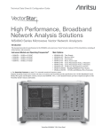
Vector Network Analyzers . . . . . . . . . . . . . . . . . . . 360
Millimeter Wave Vector Network Analyzer . . . . . . . 365
Broadband Vector Network Analyzer . . . . . . . . . . . 368
Vector Network Analyzer Automatic Calibrator . . . . 370
VNA and VNMS Calibration Kits . . . . . . . . . . . . . . 372
VNA and VNMS Verification Kits . . . . . . . . . . . . . . 374
Network Analyzers . . . . . . . . . . . . . . . . . . . . . 375, 381
Millimeter Wave Measurement System . . . . . . . . . 379
Scalar Network Analyzer . . . . . . . . . . . . . . . . . . . . 386
Reflection Bridges . . . . . . . . . . . . . . . . . . . . . . . . . 386
Transformers . . . . . . . . . . . . . . . . . . . . . . . . . . . . . 386
349
NETWORK ANALYZERS
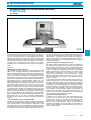
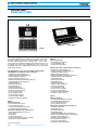
VECTOR NETWORK MEASUREMENT SYSTEMS
MS4622A/B, MS4623A/B
10 MHz to 3 GHz
10 MHz to 6 GHz
Innovative Manufacturing Solutions for Measuring S-Parameters, NF, P1dB, IMD, and 3-Port Devices
GPIB
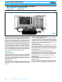
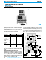
Anritsu has a new family of RF Vector Network Measurement
Systems, the MS462XA and MS462XB. Code named Scorpion®, the
MS462XX line is much more capable than traditional VNAs. With
Scorpion’s all new measurement options of vector error-corrected
Noise Figure, Intermodulation Distortion, Third Measurement Port,
and Harmonics, they create a total test solution. And, when you add
the standard benefits of outstanding dynamic range and blazing fast
measurement speed, you have a truly innovative solution for a manufacturing test environment! Scorpion’s optional AutoCal® feature also provides a capability for achieving fast, accurate, and highly repeatable calibrations without the need for an external controller. By
using AutoCal® standard connector types or test port cable converters, you can calibrate directly using Type N, K, 3.5 mm, or SMA connectors. Planned upgrades include adapter characterization with the
ability to calibrate using 7/16 or TNC type connectors.
Performance
• Measurement speed
With point-to-point, fully phase-locked, fully error-corrected sweep
speeds as fast as 150 µsec per point, Scorpion® provides the realtime measurement speed required for your production line. Its Tune
Mode feature offers the advantage of maintaining a full 12-term calibration while simultaneously optimizing sweep speed for the S-parameter measurements of interest.
• Dynamic range
The MS462XX family provides system dynamic range of up to 125
dB. This dynamic range, coupled with an impressive measurement
speed, lets you tune 2- or 3-port devices with nulls as low as 100 dB
in real time.
350
For product ordering information, see pages 4 – 10
• Test sequencing / keyboard control
For ease in automating repetitive set-ups, calibrations, measurements,
or other functions, Scorpion® implements a Test Sequencing (Macro)
capability. It can internally store up to seven different sequences and
run them directly from either the front panel or an external AT-style
keyboard. You can use the supplied keyboard-function-key overlay to
fully operate the unit without touching its front panel.
• 3-Port measurements
Improve and simplify calibrations and measurements of 3-port devices by adding the optional third measurement port. The Scorpion®
family is capable of fully calibrating 3-port measurement setups. This
maximizes the accuracy of 3-port measurements without the need
for making time-consuming and error-inducing connector disconnects and reconnects.
• Second internal source with third measurement port
Fully characterize any device that requires two independent sources.
Also the testing of passive 3-port devices such as duplexers, circulators/isolators, and mixers – as well as two-tone intermodulation
testing of active devices – is greatly simplified using this option.
• Pass/fail testing
Evaluate test data using single and segmented limit lines. Create upper and lower trace boundaries of go/no-go testing.
• Marker functions
Use up to 12 independent markers to collect data at points of interest, to set boundaries for a marker sweep, or to automatically calculate characteristics such as 3 dB bandwidth, shape factor, and Q.
NETWORK ANALYZERS
Performance and functions
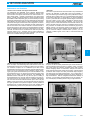
• Vector error-corrected noise figure measurements
The MS4622B and MS4623B Vector Network Measurement
Systems deliver the industry’s first ever capability for making vector
error-corrected noise figure measurements on active devices in today’s hottest market – wireless communications. The Noise Figure
options, 4 and 4B, covering the frequency ranges of 50 MHz to 3 GHz
and 50 MHz to 6 GHz respectively, give you the functionality for making
noise figure measurements much more accurately than has ever before
been possible. This option allows for making S-parameter measurements and noise figure measurements with a single test connection.
The measurement setup can be configured to make measurements
with the noise source set in either an internal or an external mode. In
the external mode, the noise source is connected directly to the DUT
similar to traditional scalar noise figure measurements. In the internal mode, the noise source is connected to the VNA rear panel and
internally routed to port 1. Therefore, when a 12-term calibration is
applied concurrently with the noise figure calibration, you can make
vector error-corrected noise figure measurements.
• AutoCal®
One source of potential errors and inaccuracies in any measurement
system is its calibration. A great deal of time can be wasted in a
busy manufacturing environment trying to verify calibration accuracy,
especially when multiple shifts run on several different test stations
for the same product line. For this situation, you need a calibration
system in place that offers the highest possible degree of assurance
that every station on every shift is calibrated for identical results.
With the Anritsu AutoCal® automatic calibrator, you get just that.
Simply connect a serial cable between the AutoCal® and the rear
panel of the VNA and you’re ready to go. If adapters become necessary, AutoCal® can handle them with its revolutionary approach to
adapter removal. This approach avoids the necessity of multiple
calibrations commonly used in adapter removal calibrations. By using the AutoCal ® adapter characterization process, you can
calibrate in a SMA, Type N, 3.5mm, TNC, or 7/16 environment with
confidence.
7
• Built-in third measurement port and second internal source
Some of today’s most demanding VNA measurements involve the
characterization and tuning of multiple port devices such as duplexers, combiners, couplers, etc. In a traditional 2-port VNA, the full
characterization and tuning of such devices presents significant challenges in terms of measurement speed, calibration, and the switching of input signals and measurement ports. With the addition of the
third measurement port, the simplicity and speed with which these
devices can be tested is greatly enhanced. The MS4622B and
MS4623B network analyzers not only offer the option of adding a
third measurement port, they also offer the industry’s first ever second internal source. This second source is completely independent
from the main source that switches between ports 1 and 2. By the
addition of this second source, the potential now exists for replacing
the signal generators and spectrum analyzers currently needed to
characterize the non-linear effects that occur when multiple tones
are simultaneously present in the pass-band of an active device.
• Mixer measurements
Scorpion can also accurately characterize your mixers and other frequency-translating devices (FTDs) for isolation, match, conversion
loss, noise figure and frequency translated group delay (FTGD).
Without changing cables or instruments, Scorpion can make all
these measurements quickly, easily and accurately. Add an external
synthesizer and Scorpion can easily orchestrate swept frequency
and swept power mixer IMD measurements. You no longer have to
buy and integrate five separate instruments to perform these everyday measurements. With the integrated measurement flexibility of
Scorpion, you can design and manufacture all of your passive, active, and frequency translating devices using a single instrument.
http://www.anritsu.com
351
NETWORK ANALYZERS
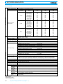
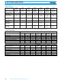
Test port characteristics
Specifications
Standard connector type
N female
Optional connector types
3.5 mm female, 3.5 mm male, GPC-7, N male
Measurement port
characteristics
Source specifications
Directivity
(dB)
Source match
(dB)
Load match
(dB)
3.5 mm
10 to 1000∗1,2
1000 to 3000∗1,2
3000 to 6000∗1,2
10 to 1000∗1,3
1000 to 3000∗1,3
3000 to 6000∗1,3
10 to 1000∗4
1000 to 3000∗4
3000 to 6000∗4
>46
>44
>38
>44
>42
>37
>30
>25
>20
>44
>41
>39
>42
>40
>37
>15
>15
>15
>46
>44
>38
>44
>42
>37
>15
>15
>15
N-Type
10 to 1000∗1,2
1000 to 3000∗1,2
3000 to 6000∗1,2
10 to 1000∗1,3
1000 to 3000∗1,3
3000 to 6000∗1,3
10 to 1000∗4
1000 to 3000∗4
3000 to 6000∗4
>46
>44
>38
>44
>42
>37
>30
>25
>20
>44
>41
>39
>42
>40
>37
>15
>15
>15
>46
>44
>38
>44
>42
>37
>15
>15
>15
GPC-7
10 to 1000∗1,2
1000 to 3000∗1,2
3000 to 6000∗1,2
10 to 1000∗1,3
1000 to 3000∗1,3
3000 to 6000∗1,3
10 to 1000∗4
1000 to 3000∗4
3000 to 6000∗4
>46
>44
>38
>44
>42
>37
>30
>25
>20
>44
>41
>39
>42
>40
>37
>15
>15
>15
>46
>44
>38
>44
>42
>37
>15
>15
>15
MS4622A/B, 10 MHz to 3 GHz
MS4623A/B, 10 MHz to 6 GHz
Frequency resolution
1Hz
Frequency stability (with
internal time base) – aging
<5x10⁻⁶ / year
Temperature
<5x10⁻⁶ over +15°C to +50°C
MS4622A Transmission/Reflection Test Set
+10 to –85 dBm
MS4622B Active Reversing Test Set
+10 to –85 dBm
MS4622B (Opt 3) w/ 2nd Source, 3rd Test Port & S/A.
+10 to –85 dBm
MS4622B (Opt 4) w/ Noise Figure
+7 to –85 dBm
MS4622B (Opt 6) w/ 3rd Test Port
+10 to –85 dBm
MS4623A Transmission/Reflection Test Set
+10 to –85 dBm
MS4623B Active Reversing Test Set
+7 to –85 dBm
MS4623B (Opt 3) w/ 2nd Source, 3rd Test Port & S/A
+7 to –85 dBm
MS4623B (Opt 4) w/ Noise Figure (3 GHz only)
+5 to –85 dBm
MS4623B (Opt 6) w/ 3rd Test Port
+7 to –85 dBm
Power control range
≥ 20 dB. The minimum absolute level for power sweep is –15 dBm while the maximum power output for a unit is +10 dBm.
Source power level
The source power (dBm) may be set from the front panel menu or via GPIB. Port 1 power level is settable from
+10 dBm (on the simpler test sets, ranging to +5 dBm on the most complex) to –15 dBm with 0.01 dB resolution.
In addition, the port 1 (& port 3) power may be attenuated in 10 dB steps using the internal 70 dB step attenuator.
Power level accuracy
±1 dB (no flat power calibration applied; full-band frequency sweep at –15 dBm, 0 dBm, and maximum rated power)
Level test port power
The power at all sweep frequencies is leveled to within ±1dB. Only port 1 and port 3 (if installed) can be externally leveled.
Harmonics and spurious
<–30 dBc at maximum rated power
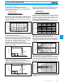
Sweep type
Linear, CW, Marker, or N-Discrete point sweep
Power sweep range
Source
#2
(optional)
20 dB (minimum)
Frequency range
10 MHz to 3 GHz (6 GHz)
Frequency
resolution
1 Hz
Power level
accuracy
±1 dB (no flat power calibration applied; full-band frequency sweep at –15 dBm, 0 dBm & max rated power)
Harmonics
and spurious
<–30 dBc at maximum rated power (not applicable in harmonic measurement mode)
Sweep type
Linear, CW, Marker, or N-Discrete point sweep
Power sweep
range
12-term error correction applied
Port 1 & Port 2
Optional Port 3 added
Uncorrected performance
352
Frequency
(MHz)
Frequency range
Power output range
∗1:
∗2:
∗3:
∗4:
Connector
20 dB (minimum)
For product ordering information, see pages 4 – 10
Continued on next page
Receiver specs
NETWORK ANALYZERS
Average noise level
–100 dBm in 10 Hz IF Bandwidth (< 3 GHz); Typically > –110 dBm in narrowband sweep
–90 dBm in 10 Hz IF Bandwidth (> 3 GHz); Typically > –100 dBm in narrowband sweep
Maximum
input level
+27 dBm, +20 dBm noise figure mode
Damage
level
> +30 dBm, > +23 dBm noise figure mode
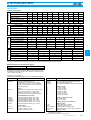
Measurement times are measured using a single trace (S21) display and one average. The measurement speeds
for the communications band are measured in a 25 MHz band from 824 – 849 MHz. The typical measurement times
displayed are as follows:
Data
points
IF bandwidth
(Hz)
10 MHz to 3 GHz
(ms)
10 MHz to 6 GHz
(ms)
Communications band
(ms)
51
30 kHz
10 kHz
3 kHz
1 kHz
300 Hz
22
27
38
71
190
25
31
41
75
194
13
18
28
62
181
101
30 kHz
10 kHz
3 kHz
1 kHz
300 Hz
32
41
63
130
366
36
45
67
135
371
21
29
51
118
355
201
30 kHz
10 kHz
3 kHz
1 kHz
300 Hz
49
68
112
247
717
54
74
118
253
723
37
52
96
231
701
401
30 kHz
10 kHz
3 kHz
1 kHz
300 Hz
85
122
212
481
1418
92
130
220
489
1426
69
97
186
456
1393
801
30 kHz
10 kHz
3 kHz
1 kHz
300 Hz
154
230
408
947
2819
166
242
420
959
2831
132
190
367
907
2777
Measurement capabilities
Measurement speed
summary
7
Parameters
S11, S21, S22, S12, S33, S23, S32, S13, S31, Harmonics, Noise Figure, Intermodulation Distortion (IMD), and user-defined
combinations of a1, a2, a3, b1, b2, and b3.
Measurement frequency
range
Frequency range of measurement can be narrowed within the calibration range without recalibration.
CW mode permits single frequency measurements, also without recalibration. In addition, the system accepts N
discrete frequency points where 2 <N <1601.
Domains
Frequency Domain, CW Draw, and optional High Speed Time (Distance) Domain
Formats
Log Magnitude, Phase, Log Magnitude & Phase, Smith Chart (Impedance), Smith Chart (Admittance), Linear Polar, Log
Polar, Group Delay, Linear Magnitude, Linear Magnitude and Phase, Real, Imaginary, Real & Imaginary, SWR, and Power
Data points
1601 maximum. Number of data points can be switched to a value of 801, 401, 201, 101, 51, 15, or 3 points without
recalibration (if 1601 points were used in the calibration). In addition, the system accepts an arbitrary set of N discrete
data points where 2 ≤N ≤1601. CW mode permits selection of a single data point without recalibration.
Reference delay
Can be entered in time or in distance (when the dielectric constant is entered). Automatic reference delay feature adds the
correct electrical length compensation at the push of a button. Software compensation for the electrical length difference
between reference and test is always accurate and stable since measurement frequencies are always synthesized.
In addition, the system compensates reference phase delay for dispersive transmission media such as microstrip.
Alternate sweep
Allows the ability to decouple channel 1 and 2 from channel 3 and 4 for the following parameters: correction type,
start and stop frequencies, number of data points, markers, sweep time, averaging, smoothing, and IF bandwidth.
Markers
Twelve independent markers can be used to read out simultaneous measurement data. In alternate sweep mode there
are sets of markers for each frequency sweep. In delta reference marker mode, any one marker can be selected as the
reference for the other eleven. Markers can be directed automatically to the minimum or maximum of a data trace.
Enhanced markers
Marker search for a level or bandwidth, displaying an active marker for each channel, and discrete or continuous
(interpolated) markers. Identifies the X dB bandwidth of amplifiers, filters, and other frequency sensitive devices.
Marker sweep
Sweeps upward in frequency between any two markers. Recalibration is not required during the marker sweep.
Limit lines
Either single or segmented limit lines can be displayed. Two limit lines are available for each trace.
Single limit readouts
Interpolation algorithm determines the exact intersection frequencies of data traces and limit lines.
Segmented limit lines
A total of 20 segments (10 upper and 10 lower) can be generated per data trace. Complete segmented traces can
be offset in both frequency and amplitude.
Test limits
Both single and segmented limits can be used for PASS/FAIL testing. PASS or FAIL status is indicated on the display
after each sweep. In addition, PASS/FAIL status is output through the rear panel I/O connector as selectable TTL levels
(PASS=0V, FAIL=+5V, or PASS=+5V, FAIL=0V).
Tune mode
Tune Mode optimizes sweep speed in tuning applications by updating forward S-parameters more frequently than
reverse ones. This mode lets users select the ratio of forward sweeps to reverse sweeps after a full 12-term calibration.
The ratio of forward sweeps to reverse sweeps can be set anywhere between 1:1 to 10,000:1.
Power sweep measurements
Both Swept Power Gain Compression and Swept Frequency Gain Compression modes are available.
Sequencing
Seven measurement sequences can be created, stored, edited, and run from the front panel. Sequences can include
front-panel functions as well as user-definable control statements. Sequences can be run from either the unit front
panel, via GPIB, or from an AT-style keyboard plugged into the front panel.
Harmonic measurement
Measurement/display of fundamental, 2nd, 3rd, 4th, 5th, 6th, 7th, 8th, & 9th harmonic
Continued on next page
http://www.anritsu.com
353
Display capabilities
NETWORK ANALYZERS
Display channels
Four, each of which can display any S-parameter or user-defined parameter in any format with up to two traces per
channel for a maximum of eight traces simultaneously. Each channel is also capable of displaying harmonics, noise figure,
intermodulation distortion, or time domain trace. A single channel, two channels (1 and 3, or 2 and 4), or all four channels
can be displayed simultaneously. Channels 1 and 3, or channels 2 and 4, can be overlaid for rectilinear graph types.
Trace overlay
Displays two data traces on the active channel’s graticule simultaneously. The overlaid trace is displayed in yellow and
the primary trace is displayed in red.
Trace memory
A separate memory for each channel can be used to store measurement data for later display or subtraction, addition,
multiplication or division with current measurement data.
Blank frequency information
Blanking function removes all references to displayed frequencies on the LCD. Frequency blanking can only be
restored through a system reset or GPIB command.
Data averaging
Averaging of 1 to 4096 averages can be selected. The data averaging function is performed at each data point during
the frequency sweep. Averaging can be toggled on or off via the front panel; a front-panel LED indicates that the data
averaging function is enabled.
IF bandwidth
Soft Key selection of IF bandwidth (30 kHz, 10 kHz, 3 kHz, 1 kHz, 300 Hz, 100 Hz, 30 Hz, 10 Hz)
Trace smoothing
Computes an average over a percentage range of the data trace. The percentage of trace to be smoothed can be
selected from 0 to 20% of trace.
Group delay is measured by computing the phase change in degrees across a frequency step by applying the formula:
Group
delay
Aperture
Defined as the frequency span over which the phase change is computed at a given frequency point. The aperture can
be changed without recalibration. The minimum aperture is the frequency range divided by the number of points in
calibration and can be increased to 20% of the frequency range without recalibration. The frequency width of the
aperture and the percent of the frequency range are displayed automatically.
Range
The maximum delay range is limited to measuring no more than ±180° of phase change within the aperture set by
the number of frequency points. A frequency step size of 100 kHz corresponds to 10 microseconds.
Storage
Hard copy
Measurement enhancements
Group delay
characteristics
GPIB
Tg = –1/360 d(phase)
d(frequency)
Measurement
repeatability
(sweep to
sweep)
For continuous measurement of a through connection, RSS fluctuations due to phase and FM noise are:
1.41 {(Phase Noise)^2 + (Tg x Residual FM Noise)^2}^.5
360 (Aperture in Hz)
Accuracy
Error in Tg = Error in phase
360
+ (Tg x Aperature Freq. Error (Hz)
Aperture
Frequency
Translating
Group
Delay
(FTGD)
Allows the measurement of group delay of mixers and other translating devices by analyzing the phase shift experienced
by a modulated signal (generated internally). The above Group Delay equation applies, except that the phase change is
measured across the modulating bandwidth of the test signal instead of across frequency points. The aperture is fixed at
about 900 kHz and the range is limited to about 1 µs. The use of angle modulation keeps the measurement relatively
immune from compression and other non-linearities.
LRL/LRM calibration
capability
The LRL calibration technique uses the characteristic impedance of a length of transmission line as the calibration
standard. A full LRL calibration consists merely of two transmission line measurements, a high reflection measurement,
and an isolation measurement. The LRM calibration technique is a variation of the LRL technique that utilizes a
precision termination rather that a second length of transmission line. A third optional standard, either Line or
Match may be measured in order to extend the frequency range of the calibration. This extended calibration is achieved
by mathematically concatenating either two LRL, two LRM, or one LRL and one LRM calibration(s). Using these
techniques, full 12-term error correction can be performed on the MS462XX VNA.
Dispersion compensation
Selectable as Coaxial (non-dispersive), Waveguide, or Microstrip (dispersive)
Reference plane
Selectable as Middle of line 1 or Ends of line 1
Corrected impedance
Determined by Calibration Standards
AutoCal ®
The Scorpion™ family will incorporate internal control of the 3658X-series AutoCal ® modules.
Printer
Scorpion™ supports the HP 2225C InkJet, HP QuietJet, HP DeskJet, HP LaserJet II, III, IV, & V Series,
and Epson compatible printers with parallel (Centronics) interfaces.
They are also compatible with the ANRITSU “CAP3700” program (outputs bitmap file over GPIB) and provide bitmap
output over front panel to disk.
GPIB plotters
Scorpion™ supports the HP Models 7440A, 7470A, and 7475A and Tektronix Model HC100 plotters.
Internal memory
Ten front panel states (setup/calibration) can be stored and recalled from nonvolatile memory locations. The current
front panel setup is automatically stored in nonvolatile memory at instrument powerdown. When power is applied, the
instrument returns to its last front-panel setup. The system will be able to exchange two stored calibrations in <0.5 s.
Internal nonvolatile memory
Used to store and recall measurement and calibration data and frontpanel setups. All files are MS-DOS compatible.
Internal floppy disk drive
A 3.5 inch diskette drive with 1.44 Mb formatted capacity is used to load measurement programs and to store and
recall measurement and calibration data and front-panel setups.
Measurement data
102.8 kb per 1601 point S-parameter data file
Calibration data
187.3 kb per 1601 point S-parameter data file (12-term cal plus setup)
Trace memory file
12.8 kb per 1601 point channel
GPIB interfaces
2 ports
System GPIB (IEEE-488.2)
Connects to an external controller for use in remote programming of the network analyzer. Address can be set from the
front panel and can range from 1 to 30.
Dedicated GPIB
Connects to external peripherals for network analyzer controlled operations (e.g. GPIB plotters, frequency counters,
frequency synthesizers, and power meters).
Continued on next page
354
For product ordering information, see pages 4 – 10
General
Power requirements
85-240 V, 48-63 Hz, 540 VA maximum
Dimensions
222H x 425W x 450D mm (8.75 x 16.75 x 17.75 in)
Weight
16 kg (35 lb)
Environmental
NETWORK ANALYZERS
Storage temperature
range
–40°C to +75°C.
Operating temperature
range
0°C to +50°C (specifications apply at 23°C ±3 °C).
Relative humidity
5% to 95% at +40°C.
EMC Directive - 89/336/EEC
EN50081-1:1992
EMC
CISPR-11:1990/EN55011:1991 Group 1 Class A
Meets the emmissions and
immunity requirements of:
IMMUNITY Standard
IEC 1000-4-2:1995/prEN50082-1:1995 - 4kV CD, 8kV AD
IEC 1000-4-3:1995/ENV50140:1994 - 3V/m
IEC 1000-4-4:1995/prEN50082-1:1995 -500V SL; 1000V PL
IEC 1000-4-5:1995/prEN50082-1:1995 - 2kV L-E, 1kV L-L
IEC 1000-4-6:1995/ENV50141:1994
IEC 1000-4-8:1995/prEN50082-1:1995
IEC 1000-4-11:1995/prEN50082-1:1995
Safety
Meets safety requirements of Low Voltage/Safety Standard
72/23/EEC - EN61010-1:1993
Ordering information
Please specify model/order number, name, and quantity when ordering.
Model/Order No.
MS4622A
MS4622B
MS4623A
MS4623B
Option
Option
Option
Option
Option
Option
Option
Option
1
2
3A
3B
4∗1
4B∗1
5
6∗2
Option
Option
Option
Option
Option
7
8
10
11∗3
13
Name
Main frame
10MHz – 3GHz
10MHz – 3GHz
10MHz – 6GHz
10MHz – 6GHz
transmission/reflection
active reversing
transmission/reflection
active reversing
Options
Rack mount kit with slides
Time domain
2nd internal source (3 GHz source) + 3rd port
2nd internal source (6 GHz source) + 3rd port
Noise figure 50 MHz to 3 GHz (only for B models)
Noise figure 50 MHz to 6 GHz (only for B models)
Frequency translation group delay
3rd test port (B models; for use with external
synthesizer)
T/R step attenuator (only for A models, standard on B)
Harmonic measurement
AutoCal ® control
Test Port connector
Intermodulation distortion
36581NNF/1
36581KKF/1
AutoCal ®
AutoCal ®, Type N, 10 MHz to 6 GHz
AutoCal ®, Type K, 10 MHz to 6 GHz
NC346A
NC346B
Noise sources
5 dB ENR noise source (3.5 mm)
15 dB ENR noise source (3.5 mm)
Model/Order No.
Name
3750LF
3751LF
3753LF
Calibration kits
SMA/3.5 mm RF Cal Kit ≤6 GHz
GPC-7 RF Cal Kit ≤6 GHz
50 Ohm, Type N, RF Cal Kit ≤6 GHz
3663LF
3666LF
3667LF
Verification kits
Type N verification kit
SMA/3.5 mm verification kit
GPC-7 verification kit
15LL50-0.3A
15LL50-0.6A
15LLF50-0.3A
15LLF50-0.6A
15NN50-0.3B
15NN50-0.6B
15NNF50-0.3B
15NNF50-0.6B
Accessories
3.5 mm Male-Male Cable, 30 cm
3.5 mm Male-Male Cable, 60 cm
3.5 mm Male-Female Cable, 30 cm
3.5 mm Male-Female Cable, 60 cm
Type N Male-Male Cable, 30 cm
Type N Male-Male Cable, 60 cm
Type N Male-Female Cable, 30 cm
Type N Male-Female Cable, 60 cm
7
∗1: Does not include noise source
∗2: Port 3 is a receiving port only, unless using an external synthesizer.
∗3: Standard connector is N-female, no cost option for 3.5 mm (male),
3.5mm (female), N-male, or GPC-7
http://www.anritsu.com
355
NETWORK ANALYZERS
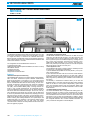
VECTOR NETWORK MEASUREMENT SYSTEM / DIRECT-ACCESS RECEIVER
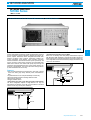
MS4622C, MS4623C
10 MHZ to 3 GHz
10 MHz to 6 GHz
For Measuring Antennas, Frequency Conversion, and Multiple-Output Devices
GPIB
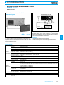
The MS462XC series of RF vector network analyzers are configured
as direct-access receivers for antenna, frequency conversion, and
multiple output device measurements. The MS462XC offers ultimate
flexibility to meet most receiver measurement needs while maintaining the ability to measure all four S parameters with the addition of a
reflectometer setup at the front end of the receiver.
The MS462XC series offers two wide-band RF models covering the
10 MHz to 3 GHz or 6 GHz ranges, MS4622C, and MS4623C, respectively.
Applications
• Mixers
Mixers are integral components of most measurement systems.
Mixer measurements are complicated by the fact that a LO is required
and multiple frequencies are involved in the complete measurement
of a mixer. In addition the mixer is non-linear so power levels must be
carefully considered, and in many instances non-linear effects such
as compression and intermodulation distortion must be measured.
The MS462XC has many features that simplify mixer measurements.
The MS462XC can include two built in sources, to provide both the LO
356
For product ordering information, see pages 4 – 10
and RF signal required by the mixer – the system automatically tunes
the receiver to the appropriate IF frequency. The unit can control additional external sources as required for intermodulation measurements.
The setup of the sources is obviously quite important in a mixer measurement. The Mixer device type simplifies this task somewhat. It allows the quick selection of which source is to be the DUT LO. It allows simple selection of a fixed LO or fixed IF measurement scenario
(and specifying that LO or IF frequency). And, it informs the receiver
of what kind of DUT conversion to expect (up conversion |RF+LO|,
down conversion |RF-LO|, or no conversions might be used for a
quick leakage measurement). Activating the mixer device type also
performs the important function of turning on both internal sources
for front panel access (usually using ports 1 and 3 driving, port 2 being the receive port). Two ports are not allowed to drive simultaneously during normal S-parameter measurements.
• Antennas
Far-field measurements are enhanced with the speed of taking data
over GPIB, using fast CW mode. Rates of 1 ms/data point can be
achieved using internal triggering, 1.3 ms/point with external triggering, and 1.6 ms/point with GPIB triggering.
NETWORK ANALYZERS
Specifications
Ordering information
General measurement and enhancement display capabilities are the
same as those for the MS4622A/B, MS4623A/B.
Please specify model/order number, name, and quantity when ordering.
Number of channels
Four measurement channels
Operating port power
(A1, A2, B1 and B2)
–5 dBm for 0.1 dB compression
Maximum port power
for no damage
+20 dBm
Noise floor
–100 dBm@10 Hz IF bandwidth (<3 GHz),
typically >–120 dBm in narrowband sweep;
–100 dBm@10 Hz IF bandwidth (>3 GHz),
typically >–110 dBm in narrowband sweep
System dynamic range
97 dB
Power output range
(ports 1, 2 and 3)
MS4622C: +10 to –85 dBm
MS4623C: +7 to –85 dBm
Source match
(RF1, RF2 and RF3)
–15 dB (uncorrected)
Port match
(A1, A2, B1 and B2)
–12 dB (uncorrected)
Frequency range
MS4622C: 10 MHz to 3 GHz
MS4623C: 10 MHz to 6 GHz
2nd internal source
Optional
Intermodulation Distortion
Optional
IMD (3rd order)
dynamic range
70 dB with 10 Hz IF bandwidth @ 300 kHz
tone separation and @ –20 dBm tone levels
IMD accuracy
±1 dB @ > –60 dBm levels
Power measurement
accuracy
±1 dB without flat power calibration
±0.1 dB with flat power calibration
Full reversing
transfer switch
Provided
Model/Order No.
Name
MS4622C
MS4623C
Mainframe
10 MHz to 3 GHz direct receiver access
10 MHz to 6 GHz direct receiver access
Option
Option
Option
Option
Option
Option
Option
Option
Option
Option
Option
Options
Rack mount kit with slides
Time domain
2nd internal source (3 GHz source) + 3rd port
2nd internal source (3 GHz source) + 3rd port
Frequency translated group delay
3rd test port (only for B and C models)
T/R step attenuator (only for A models, standard on B)
Harmonic measurement
AutoCal ® control
Test Port connector
Intermodulation distortion
1
2
3C
3D
5
6
7
8∗1
10
11∗2
13
∗1: Subject to frequency range limitations imposed by test set.
∗2: Standard connector is N-female, no cost option for 3.5 mm (male),
3.5mm (female), N-male, or GPC-7
7
http://www.anritsu.com
357
NETWORK ANALYZERS
POWER AMPLIFIER TEST SYSTEM (PATS)
ME7840A
800 to 2400 MHz, 100 Watts
Easy-to-Use System for Power Amplifier Design and Manufacturing
GPIB
PATS is a flexible, easy-to-use system for power amplifier design and
manufacturing. It allows real-time, simultaneous tuning of various
amplifier parameters, including IMD and hot S22 in both swept-frequency and swept-power modes. Adjacent Channel Power Ratio
(ACPR) shows the performance of your PA under real-world modulated conditions and is available with swept power mode. The following table summarizes the PATS measurement capability between
800 and 2400 MHz for applications up to 100 Watts.
• Scorpion PA Navigator
The Scorpion PA Navigator is installed on your computer to orchestrate
the PATS measurements. The computer should be a Pentium II at 200
MHz or equivalent system with a GPIB Card (computer not included).
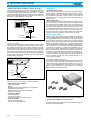
PATS Block Diagram
The following block diagram depicts the standard MS4782D Test Set
design. Anritsu can configure and optimize a custom test set for your
specific requirements.
Measurement capabilities:
CW
Swept Frequency
Swept Power
(as fast as 150 µsecs/pt) (as fast as 150 µsecs/pt)
√
S-Parameters
Hot S22
√
√
√
IMD, TOI (two-tone):
3rd, 5th, 7th, & 9th
√
√
√
√
√
SOURCE 1
GPIB
SYSTEM
CONTROLLER
(PC)
√∗
ACPR
Gain Compression:
P1 dB
AM/PM
SOURCE 2
√
MS462XC DIRECT RECEIVER
ACCESS SCORPION®
Measurements
√
√
REVERSE FORWARD
TRANSFER
SWITCH
GPIB
STEP
ATTENUATORS
70dB, 10dB/step
ANALOG IN
RECEIVERS
EXT I/O
Harmonics:
Magnitude
Phase
√
Power Added
Efficiency (PAE)
√
√
√
√
A1
N
N
SMA
B1
SMA
B2
SMA
N
S
S
S
A2
RF2
SMA
N
CONTROL
LINES
N
S
N
S
√
COMBINER
√
PATS consists of three distinct parts: The MS462xC Vector Network
Measurement System, the MS4782D Test Set, and the Scorpion PA
Navigator.
• MS462xC Vector Network Measurement System
The MS462xC is the Direct Receiver Access (DRA) configuration for
the MS462xx family of Vector Network Measurement Systems (VNMS).
The MS462xC series is available in two wide-band RF models covering the 10 MHz to 3 GHz or 6 GHz range (MS4622C and
MS4623C respectively).
• MS4782D Test Set
The MS4782D Test Set provides the necessary hardware to interface between your power amplifier and the VNMS.
For product ordering information, see pages 4 – 10
C3
-30dB
S
100W
TERMINATION
√
∗ Swept power speed is related to external source
358
RF1
OPTIONAL
EXTERNAL
PREAMPLIFIERS
LIMITER
MS4782D TYPICAL TEST SET
Drain Current
√
√
RF3
C2
*OPTIONAL
EXTERNAL
CIRCULATOR
S
C1
-30dB
OPTIONAL
SPECTRUM
ANALYZER
STEP
ATTENUATOR
70dB, 10dB/step
OPTIONAL
POWER
METER
-30dB
-30dB
N
OPTIONAL
MODULATION
SYNTHESIZER
S
S
N
N
N
AUT
OPTIONAL
EXTERNAL
PRE-AMP
*Circulator is required only for S22 measurement.
If S22 is not required, port C1 is connected to C2
as shown by dashed line.
POWER
SUPPLY
OPTIONAL
CURRENT PROBE
NETWORK ANALYZERS
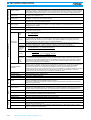
PATS Software Results
With frequency sweeps as fast as 150 µs/point and power sweeps as
fast as 150 µs/point, you can quickly, thoroughly, and accurately
characterize your power amplifiers in real-time.
Simultaneously overlay measurements in both frequency and power
and see the results of over 250 datapoints updated twice per second.
Ordering information
Please specify model/order number, name, and quantity when ordering.
Anritsu can configure and optimize a custom test set for your specific requirements. The following information represents the standard
configuration and options.
Model/Order No.
ME7840A
MS4623C∗1,2
MS4600/3D
MS4600/8
MS4600/13
MS4782D
43425
ME7840/1
ME7840/2
ME7840/3
1000-50
1000-52
1000-53
2000-1067
Specifications
Characteristic
Value
Notes
Amplifier Under Test
100W max
Power Output
Without Hot S22 provision
(Contact Anritsu for custom designs
for higher power)
Bandwidth through
Test Set
Without S22 provision
(Contact Anritsu for custom designs
for different frequency ranges)
800 MHz –
2.4 GHZ
Amplifier Under Test
–85 dBm to
Input Power range
+10 dBm
available from PATS
This value is for each tone, at
combiner input. Provision for
preamplifiers provided for greater
levels
IMD (3rd order)
Dynamic Range
70 dB min
With 10 Hz IF bandwidth @ 300 kHz
tone separation and –20 dBm tone
levels
±1 dB max
@ >–60 dBc levels
IMD Accuracy
Port Power Accuracy
±0.1 dB typical With flat power calibration
±1 dB max
Without flat power calibration
Dynamic Range
80 dB min
Over-all system including Test Set
Port Match
(test ports 1 & 2)
40 dB min
Corrected value
Port Match
(test ports 1 & 2)
13 dB min
Uncorrected value
Directivity
40 dB
800 MHz – 2.4 GHz, Corrected value
2000-1085
Name
Main frame
PATS, 800 to 2400 MHz, 100 Watts
Scorpion®, DRA configuration, 10 MHz to 6 GHz
Scorpion® optional 6 GHz internal source with
3rd test port
Scorpion® optional harmonic measurement application
Scorpion® optional intermodulation distortion application
PATS Test Set (100 Watts, 800 – 2400 MHz)∗3
Accessories and interconnect kit
Scorpion PA Navigator
Replace MS4623C with MS4622C (3 GHz option)
Replace MS4782D test set with MS4782A
Delete Test Set
Circulators
Circulators may be required for measurements of Hot S22:
Circulator, 800 – 1000 MHz, 20 dB min, 50 Watts
Max AUT Power
Circulator, 1.8 – 2.5 GHz, 20 dB min, 50 Watts
Max AUT Power, (connecting cable(s) not included)
Circulator, 1.8 – 2.5 GHz, 22 dB min, 79 Watts
Max AUT Power
Note: All circulators have 3 SMA female connectors.
Current Probes
Current Probes are required for drain current and Power
Added Efficiency (PAE) calculations:
Current Probe
Max current: 100mV/A:10A, 10mV/A:100A
Accuracy (at lesser current range setting):
3% of reading ±50mA
Current Probe
Max current: 1mV/mA:1A, 10mV/A:80A
Accuracy (at lesser current range setting):
2% of reading ±5mA
3750LF
3753LF
Calibration kits
SMA/3.5 mm RF Cal Kit (6 GHz)
Type N RF Cal Kit (6 GHz)
36581NNF/1
36581KKF/1
AutoCal®
AutoCal, Type N, 10 MHz to 6 GHz
AutoCal, Type K, 10 MHz to 6 GHz
15LL50-0.3A
15LL50-0.6A
15LLF50-0.3A
15LLF50-0.6A
15NN50-0.3B
15NN50-0.6B
15NNF50-0.3B
15NNF50-0.6B
Economy cables
3.5 mm Male-Male Cable, 30 cm
3.5 mm Male-Male Cable, 60 cm
3.5 mm Male-Female Cable, 30 cm
3.5 mm Male-Female Cable, 60 cm
Type N Male-Male Cable, 30 cm
Type N Male-Male Cable, 60 cm
Type N Male-Female Cable, 30 cm
Type N Male-Female Cable, 60 cm
∗1: ME7840A standard connector type is N-female.
∗2: Scorpion® DRA rear panel Reference Channel Connectors a1, a2, b1,
and b2 are SMA-female connectors.
∗3: Special test sets can be configured for other power levels and frequency
ranges.
http://www.anritsu.com
359
7
NETWORK ANALYZERS
VECTOR NETWORK ANALYZERS
37100C, 37200C, 37300C Series
22.5 MHz to 65 GHz
For Fast and Accurate S-Parameter Measurements
GPIB
The 37200C and 37300C series microwave vector network analyzers
(VNAs) are high performance tools designed to make fast and accurate
S-parameter measurements across the 22.5 MHz to 65 GHz range.
These network analyzers integrate a synthesized source, S-parameter test set, and tuned receiver into a single compact package that is
ideal for benchtop testing.
Code named Lightning, the 37200C and 37300C offer new levels of
measurement capabilities to speed manufacturing test and increase
throughput. Choose the instrument model and options that best suit
your application and budget.
The 37200C series is designed for passive device measurements,
while the 37300C series adds active device measurement capabilities. The 37217C/37317C is an economical choice for lower frequency component testing up to 8.6 GHz. Higher frequency solutions
to 13.5, 20, 40, 50, and 65 GHz are available in microwave models
37225C/37325C, 37247C/37347C, 37269C/37369C, 37277C/37377C,
and 37297C/37397C, respectively.
The 37100C series microwave vector network analyzers are configured as direct-access receivers for antenna, frequency conversion,
and multiple output device measurements. The 37100C offers ultimate flexibility to meet most receiver measurement needs while
maintaining the ability to measure all four S parameters with the addition of a reflectometer setup at the front end of the receiver.
The 37100C series offers two wide-band microwave models covering the 22.5 MHz to 20 GHz or 40 GHz ranges, 37147C, and
37169C, respectively.
Features
• Next generation VNA technology
The 37100C/37200C/37300C series incorporates a higher speed
processor and faster power sweep capability.
• High speed data transfer and control
For maximum efficiency, dual GPIB ports are standard on every
37100C/37200C/37300C series VNA. High-speed transfers across
the analyzer's IEEE 488.2 GPIB bus minimize data collection times.
The second GPIB port is dedicated to control of peripheral devices
such as printers, plotters, power meters, and frequency synthesizers. The 37100C/37200C/37300C series maximizes throughput by
combining fast, error-corrected sweeps with high-speed data transfers.
Measurement throughput for the 37100C/37200C/37300C series
ranks as the fastest of any microwave analyzer in the industry.
360
For product ordering information, see pages 4 – 10
• Compact size
The 37200C/37300C series analyzers integrate a fast sweeping
synthesized source, auto-reversing S-parameter test set, and fourchannel receiver into a single compact package. The 37100C series
analyzers integrate a fast sweeping synthesized source and fourchannel receiver into a single compact package and provides direct
access to all four receiver samplers via the front panel. Components
within the analyzer have been integrated to reduce cost and weight
and improve the instrument's long-term reliability. Despite its small
size, the 37100C/37200C/37300C series analyzers rival the performance normally found in larger, more expensive vector systems.
• Built-in mass storage
Testing devices with multiple setups is now easier. A built-in hard
disk drive rapidly stores and recalls frequently used front panel
setups and calibrations. Store your complete test setup including limit lines and frequency markers. Create descriptive file names to assist multiple users or device types. The high storage capability of the
internal hard disk means there is space for Iiterally hundreds of calibrations, front panel setups, and data traces. In secure environments, the internal hard disk can be removed and either an external
drive on the SCSI port or the internal 1.44 MB floppy drive can be
used for uploading proprietary setups.
• Fast synthesized sweeps
Measurement update rates of less than 2 ms per point are possible
with the 37100C/37200C/37300C series analyzers. Each data point
is fully phase-locked and vector-error-corrected for optimum accuracy.
Realize near real-time updates with the instrument's tune mode.
The internal source frequency resolution of 1 kHz satisfies most
wide- and narrow-band requirements. Devices requiring more frequency definition can be evaluated with 1 Hz frequency resolution
(Option 10A).
• Time domain analysis
Analyze impedance discontinuities as a function of time or distance
with the 37100C/37200C/37300C's high-speed time domain (Option 2A).
Isolate individual reflections in time and evaluate their effects in the
frequency domain. Remove the effects of device packages and fixturing with time domain gating to see the actual performance of your
designs. Use the independent display channels to view the response
of your designs before, during, and after time domain processing.
The software provides four different windowing functions to optimize
NETWORK ANALYZERS
dynamic range and resolution. The exclusive phasor impulse mode
will show you the true impedance characteristics of mismatches in
waveguide, microstrip, and other band-limited media.
• Multiple source control
Conveniently test mixers and multipliers through the 37100C/
37200C/37300C's multiple source control. Separately control the frequency of two sources and a receiver without the need for an external controller. Independently specify the sweep ranges and output
powers of the sources and the sweep range of the receiver to accommodate testing of frequency translation devices.
• LabVIEW® compatibility
Standard with every 37100C/37200C/37300C series analyzer is
National Instruments LabVIEW® instrument driver. Create custom
test programs (virtual instruments) in less time with LabVIEW®'s
graphical programming environment. Take advantage of the network
analyzer's high data throughput for tuning operations. Fast data
transfers over GPIB permit near realtime updates on your PC's display.
Customize programs to automatically display, test, and document
measurement results. Reuse virtual instruments in other test routines to
minimize program development time. LabVIEW® gives you full access to more than 900 mnemonics in the 37100C/37200C/37300C
analyzer's command set for complete automated data collection and
analysis.
• Amplifiers (available on 37300C series only)
Easily measure amplifier gain compression vs. input power or frequency. Power meter assisted flat output power calibration provides
capability to measure power in dBm. A 1 watt, 70 dB (60 dB on >40 GHz
models) step attenuator in the port 1 path, and a 40 dB step attenuator in the port 2 path, coupled with 20 dB ALC range, give complete
control to characterize virtually any amplifier. This range is reduced
to 12 dB at frequencies >50 GHz. Internal bias tees simplify DC biasing of your active designs. A front panel loop allows external amplifier insertion, increasing port 1 power up to 1 watt for high input
power amplifiers.
• Mixers
One source of potential errors and inaccuracies in any network analyzer system is the calibration of that system. The Anritsu AutoCal
automatic calibrator is designed to speed and simplify the calibration
of your 37200C/37300C VNA. Using the built-in software support
and an AutoCal module connected to the serial port on the rear panel
of the instrument, you are ready to make fast, accurate, and repeatable calibrations.
Mixers as multiport devices take advantage of the multiple source
control and set-on receiver mode features.
The 37100C/37200C/37300C can be configured to measure the relative harmonic level of test devices with set-on receiver mode capability. The 37100C/37200C/37300C's unique phase locking scheme allows it to operate as a tuned receiver by locking all of its local oscillators to its internal crystal reference oscillator. Set-on receiver
mode capability significantly increases the versatility of the
37100C/37200C/37300C VNA in applications that check for harmonics,
intermodulation products, and signals of known frequency.
Multiple source control capability allows a user to independently control the frequencies of two sources and the receiver without the need
for an external controller. The frequency ranges and output powers
of the two sources may be specified. A frequency sweep may be
comprised of up to five separate bands, each with independent
source and receiver settings, for convenient testing of frequency
translation devices such as mixers. Up to five sub-bands may be
tested in one sweep. This feature enables users to easily test mixers,
up/down converters, multipliers, and other frequency conversion devices.
• Three-year factory warranty
• Microstrip devices
• Internally controlled AutoCal®
All 37100C/37200C/37300C series VNAs are backed with a noquestions-asked three-year warranty.
• Upgradeability
The 37100C/37200C/37300C series analyzers are designed to accommodate higher frequency ranges and more powerful features as
your requirements grow. Any 37100C/37200C/37300C series VNA
can be upgraded to any other model in the instrument family, or any
other series, to fit your changing requirements. Contact Anritsu
Customer Service to request an upgrade and an Anritsu service engineer will install the added capability and verify your system's total
performance. Upgradeability is a cost-effective approach to satisfying
today's production needs while providing the flexibility to meet tomorrow's demands. System software upgrades are as easy as inserting
new discs into the instrument's floppy drive.
Applications
• Filters
Let the analyzer's wide dynamic range show you filter rejection and
input match on the same display. Overlay traces and tune for optimum transmission and group delay responses without reduction in
sweep speed.
Further speed improvements are possible using the instrument's
tune mode. This unique feature helps users optimize sweep times in
one direction for better hand-to-eye tuning while maintaining a 12term corrected S-parameter display. Anritsu's tune mode maximizes
sweep speed and accuracy, simultaneously, by allowing you to
choose when reverse parameters are updated.
Automatically locate filter center frequency, 3 dB bandwidth,
max/min insertion loss, 0 dB points, Q, and shape factor. Instantly
measure passband phase distortions with Anritsu's automatic reference plane extension capability. A single key press quickly identifies
filter non-linear responses.
The 37200C/37300C series offers complete substrate measurement
solutions for both microstrip and coplanar waveguide (CPW) designs. The 37200C/37300C series analyzers accommodate the model 3680 series Universal Test Fixtures (UTF), calibration kits, and verification kits. Guaranteed system specifications provide assurance
that your test results are accurate and verifiable.
Completely characterize connectorless devices with the 37200C/
37300C's Line-Reflect-Line (LRL) and Line-Reflect-Match (LRM)
calibration capability. The four channel design provides true LRL/
LRM error-correction giving you the highest performance available
for in-fixture measurements. Highly reflective devices, along with
well matched ones are measured with the same degree of ease.
Automatic dispersion compensation improves measurement accuracy to help you determine phase distortions in all your microstrip designs. The result is quality measurements you can count on for your
connectorless devices.
• Antennas
Far field measurements are enhanced with the speed of taking data
over GPIB, using the 37100C in fast CW mode. Rates of 0.8 ms/point
can be achieved using internal triggering, 1.2 ms/point with external
triggering, and 1.5 ms/point with GPIB triggering.
For near field measurements, internal buffer data collection is provided to allow saving active channel measurement data from multiple sweeps without having to synchronize and collect data at the
end of each sweep. The 37100C can store up to 50,000 data point
measurements, each consisting of two real and imaginary IEEE 754
4-byte floating point numbers.
• Multiport devices
The 37100C offers direct access to all four samplers. Flat test port
power calibration using a power meter allows source calibration and
characterization of all four receiver channels. Ratioed measurements
can then be performed on any combination of the four channels.
Absolute dBm measurements can also be made through the userdefined parameter feature.
http://www.anritsu.com
361
7
NETWORK ANALYZERS
Specifications
Number of channels
Four measurement channels
Parameters
S11, S21, S12, S22; or user defined, complex input and output impedance; complex input or output admittance;
complex forward and reverse transmission
Domains
Formats
Data points
Measurement
capabilities
Reference delay
Can be entered in time or in distance. Automatic reference delay adds the correct electrical length compensation
at the push of a button. Software compensation for the electrical length difference between the reference and test
is accurate and stable since measurement frequencies are always synthesized.
Markers
Six independent markers can be used to read out measurement data. In delta-reference mode, any one marker
can be selected as the reference for the other five. Markers can automatically find critical filter parameters i.e. 3 dB
bandwidth, loss, center frequency, shape factor and Q.
Marker sweep
Measurement dynamic
range
Data averaging
Averaging of 1 to 4096 averages per data point can be selected.
IF bandwidth
Front panel switch selects four levels of IF bandwidth: 10 kHz, 1 kHz, 100 Hz and 10 Hz
Display channels
1, 2, 3 or 4 channels can be displayed. Each channel can display any S-parameter or user defined parameter in
any format with up to two traces per channel for a maximum of eight traces simultaneously.
Display type
Color LCD, 8.5” diagonally, VGA display. Color of graticule, trace data and text are user definable.
Trace overlay
Overlays two traces with the same graticule type on the same display
Trace memory
A separate memory for each channel can be used to store measurement data for later display or subtraction, addition, multiplication or division.
Scale resolution
Log mag: 0.001 dB, linear mag: 1 pU
Phase: 0.01°, group delay: 0.001 ps
Time: 0.001 ms, distance: 0.1 mm
SWR: 1 pU
Power: 0.05 dB
Autoscale
Automatically sets resolution and offset to display measurement data on the full display
Reference position
Settable to any graticule line
Display
capabilities
Signal source
capabilities
Hard copy
Storage
Remote
programming
Sweeps upward in frequency between any two markers. Recalibration is not required during the marker sweep.
Two limit lines per data trace to indicate test limits. Limits can be either single or segmented limits for testing devices pass-fail.
Table 1 gives receiver dynamic range as the ratio of maximum signal level at Port 2 (or individual sampler input)
to the noise floor.
Limits
Vector error
correction
Frequency domain, CW draw, and optional high speed time domain (Option 2A)
Log magnitude, phase, log magnitude and phase, Smith chart (impedance), Smith chart (admittance), linear polar,
log polar, group delay, linear magnitude, linear magnitude and phase, real, imaginary, real and imaginary, and SWR
1601 maximum. System also accepts an arbitrary set of N discrete data points where 2≤N≤1601.
CW mode permits selection of a single point.
Annotation
Type of measurement, vertical and horizontal scale resolution, start and stop frequencies and reference position
Error correction models
Full 12-term, one-path two-port, reflection only, transmission response
LRL/LRM
Line-Reflect-Line and Line-Reflect-Match calibration models are available for coaxial, microstrip and waveguide
transmission lines.
Source power level
Source power may be set from the 37100C/37200C/37300C front panel menu. Check table 2 for levels.
Flat power correction
The 37100C/37200C/37300C corrects for test port power variations using an external power meter. Once the port
power has been flattened, the power meter is removed and the signal source power level may be changed within
the remaining power adjustment range.
Multiple source control
Allows a user to separately control the frequency of two sources and receiver without need for an external controller.
Source #1: 37200C/37300C internal source, or any 68000C or 69000B synthesizer
Source #2: Any 68000C or 69000B synthesizer
Receiver: 37200C/37300C internal receiver
Internal 10 MHz time
base stability
Standard
With aging: <1 x 10⁻⁶/day
With temperature: <1 x 10⁻⁶ over 15˚ to 50˚C
High stability time base (Option 10A)
With aging: <1 x 10⁻⁹/day
With temperature: <5 x 10⁻⁹ over 0˚ to 55˚C
Printers
Select full screen, graphical, tabular data, and printer type. Compatible with most HP and Epson printers with a
parallel (Centronics) interface
GPIB plotters
Compatible with most HP and Tektronix plotters
Internal memory
Ten front panel states (setup) can be stored and recalled from non-volatile memory locations.
Internal hard disk drive
Used to store and recall setup and calibration files, trace data and tabular data files. All files are MS-DOS compatible.
Internal floppy disk
drive
Stores and recalls setup and calibration files from 3.5 inch 1.44 MB floppy disks. All files are MS-DOS
compatible.
Interface
GPIB (IEEE 488.2)
Addressing
Address can be set from the front panel and can range from 1 to 30.
Transfer formats
ASCII, 32-bit floating point and 64-bit floating point
Speed
150 kB/sec
Interface function codes SH1, AH1, T6, TE0, L4, LE0, SR1, RL1, PP1, DT1, DC0, C0
General
362
Test ports
GPC-7, 3.5 mm, N-type, K, and V connectors supported
Power requirements
85 to 240 V, 48 to 63 Hz, 540 VA maximum
Dimensions
432 (W) x 267 (H) x 585 (D) mm (10.5 x 17 x 23 in)
Mass
27 kg (60 lbs)
Temperature
0˚ to 50˚C (operate), –40˚ to 75˚C (storage)
For product ordering information, see pages 4 – 10
NETWORK ANALYZERS
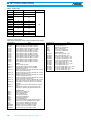
Table 1a Dynamic range (37100C)
Model
Frequency (GHz)
Max. signal into ax, bx (dBm)
Noise floor (dBm)
Receiver dynamic range (dB)
Source power (dBm, typical)
37147C
0.0225
2
20
–18
–12
–12
–122
–106
–103
104
94
91
10
8
5
37169C
0.0225
2
20
40
–18
–12
–12
–15
–122
–106
–103
–100
104
94
91
85
10
8
3
–3
Table 1b Dynamic range (37200C/37300C)
Model
37217C
37225C
37247C
37269C
37277C
37297C
37317C
37325C
37347C
37369C
37377C
37397C
Frequency
(GHz)
0.0225
2
8.6
0.04
2
13.5
0.04
2
20
0.04
2
20
40
0.04
2
20
40
50
0.04
2
20
40
50
65
0.0225
2
8.6
0.04
2
13.5
0.04
2
20
0.04
2
20
40
0.04
2
20
40
50
0.04
2
20
40
50
65
Max. signal into
port 2 (dBm)
+3
+3
+3
+20
+3
+3
+20
+3
+3
+20
+3
+3
+3
+20
+3
+3
+3
+3
+20
+3
+3
+3
+3
+3
+30
+30
+30
+30
+30
+30
+30
+30
+30
+30
+30
+30
+30
+30
+30
+30
+30
+30
+30
+30
+30
+30
+30
+30
Noise floor
(dBm)
–95
–98
–98
–70
–98
–98
–70
–98
–96
–70
–98
–95
–93
–77
–105
–97
–95
–87
–77
–105
–97
–95
–87
–77
–95
–98
–98
–65
–93
–93
–65
–93
–91
–65
–93
–90
–83
–77
–105
–97
–95
–87
–77
–105
–97
–95
–87
–77
Receiver dynamic
range (dB)
98
101
101
90
101
101
90
101
99
90
101
98
96
97
108
100
98
90
97
108
100
98
90
80
125
128
128
95
123
123
95
123
121
95
123
120
113
107
135
127
125
117
107
135
127
125
117
107
Port 1 power
(dBm, typical)
0
0
0
0
0
0
0
0
0
0
0
–5
–15
0
+5
–2
–7
–2
0
+5
–2
–7
–2
–2
0
0
0
+5
+5
+5
+5
+5
+5
+5
+5
0
–7
0
+5
–2
–7
–2
0
+5
–2
–7
–2
–2
System dynamic
range (dB)
95
98
98
70
98
98
70
98
96
70
98
90
78
77
110
95
88
85
77
110
95
88
85
75
95
98
98
70
98
98
70
98
96
70
98
90
76
77
110
95
88
85
77
110
95
88
85
75
http://www.anritsu.com
363
7
NETWORK ANALYZERS
Table 2 Power range
Model
Rated power (dBm) Minimum power (dBm)
37147C
+5
–15
37169C
–3
–23
0
–20
37269C
–15
–27
37277C
–7
–27
37297C
–7
–19
37317C
0
–95
+5
–90
Resolution (dB)
37217C
37225C
37247C
37325C
37347C
37369C
–7
–97
37377C
–7
–87
37397C
–7
–79
0.05
Ordering information
Please specify model/order number, name, and quantity when ordering.
Model/Order No.
37147C
37169C
37217C
37225C
37247C
37269C
37277C
37297C
37317C
37325C
37347C
37369C
37377C
37397C
Option 1
Option 2A
Option 4
Option 7A
Option 7N
Option 7NF
Option 7S
Option 7K
Option 10A
Option 11
Option 12
3650
Option 1
3651
Option 1
3652
Option 1
3653
3654B
3750
3751
3753
36581NNF
36581KKF
36582KKF
Name
Main frame
Direct Access Receiver (22.5 MHz to 20 GHz)
Direct Access Receiver (22.5 MHz to 40 GHz)
Vector Network Analyzer (22.5 MHz to 8.6 GHz)
Vector Network Analyzer (40 MHz to 13.5 GHz)
Vector Network Analyzer (40 MHz to 20 GHz)
Vector Network Analyzer (40 MHz to 40 GHz)
Vector Network Analyzer (40 MHz to 50 GHz)
Vector Network Analyzer (40 MHz to 65 GHz)
Vector Network Analyzer (22.5 MHz to 8.6 GHz)
Vector Network Analyzer (40 MHz to 13.5 GHz)
Vector Network Analyzer (40 MHz to 20 GHz)
Vector Network Analyzer (40 MHz to 40 GHz)
Vector Network Analyzer (40 MHz to 50 GHz)
Vector Network Analyzer (40 MHz to 65 GHz)
Options
Rack mount kit with slides
High-speed time (distance) domain capability
External SCSI-2 hard disk drive compatibility
(internal HDD removed)
Replaces universal K connector (standard) with universal
GPC-7 (37200C/37300C only)
Replaces universal K connector (standard) with universal
N-male (37200C/37300C only)
Replaces universal K connector (standard) with universal
N-female (37200C/37300C only)
Replaces universal K connector (standard) with universal
3.5 mm-male (37200C/37300C only)
Replaces universal V connector (standard) with universal
K (m) (37277C/37297C/37377C/37397C models only)
High stability (ovenized) time base and 1 Hz frequency
resolution
Reference loop extension cables (standard on 37300C
series)
Rear Panel IF Inputs (for 37x97C and 37x77C only).
Required for upgrade to ME7808A Broadband VNA.
Calibration kits
SMA/3.5 mm Calibration Kit
Adds sliding terminations
GPC-7 Calibration Kit
Adds sliding terminations
K Connector Calibration Kit
Adds sliding terminations
Type N Calibration Kit
V Connector Calibration Kit with sliding terminations
SMA/3.5 mm Economy Calibration Kit (<8.6 GHz)
GPC-7 Economy Calibration Kit (<8.6 GHz)
Type N Economy Calibration Kit (<8.6 GHz)
AutoCal, N (m) to N (f), 40 MHz to 18 GHz
AutoCal, K (m) to K (f), 40 MHz to 20 GHz
AutoCal, K (m) to K (f), 40 MHz to 40 GHz
∗ Call your Anritsu representative for 50 and 65 GHz upgrades.
364
For product ordering information, see pages 4 – 10
Model/Order No.
Name
3663
3666
3667
3668
3669B
Verification kits
Type N Verification Kit
SMA/3.5 mm Verification Kit
GPC-7 Verification Kit
K Connector Verification Kit
V Connector Verification Kit
3670A50-1
3670A50-2
3670K50-1
3670K50-2
3670V50-1
3670V50-2
3671A50-1
3671A50-2
3671S50-1
3671S50-2
3671K50-1
3671K50-2
3671V50-3
3671V50-4
Test port cables
GPC-7 semi-rigid cable, 1 foot
GPC-7 semi-rigid cable, 2 foot
K connector semi-rigid cable, 1 foot
K connector semi-rigid cable, 2 foot
V connector semi-rigid cable, 1 foot
V connector semi-rigid cable, 2 foot
GPC-7 flexible cables, 25 in. (1 pair)
GPC-7 flexible cables, 38 in.
3.5 mm flexible cables, 25 in. (1 pair)
3.5 mm flexible cables, 38 in.
K connector flexible cables, 25 in. (1 pair)
K connector flexible cables, 38 in.
V connector flexible cable, 25 in. (1 pair)
V connector flexible cable, 38 in.
NETWORK ANALYZERS
MILLIMETER WAVE VECTOR NETWORK ANALYZER
37000 Family
33 to 140 GHz
High Performance Millimeter Wave Vector Network Analysis
GPIB
7
The 37000 family millimeter wave vector network analyzer (VNA) extends the exceptional performance of the Lightning VNA family to
140 GHz. This improvement to our original millimeter wave system,
based on the 360B VNA, continues our commitment to providing the
highest quality microwave and millimeter wave test equipment available while still maintaining an intuitive user interface. The minimum
configuration for the millimeter wave VNA has a 37147C VNA, a
3735B Test Set, two synthesized sources, and a pair of millimeter
heads.
Features
• Measurement speed and accuracy
The millimeter wave VNA, based on our popular Lightning 37000
platform, offers the fastest measurement speed available in a millimeter wave VNA. Measurement speed of approximately 20 ms per
point for an 801 data point sweep means faster tuning and throughput for your millimeter wave devices. The millimeter wave system
also offers full auto-reversing, 12-term, error-corrected S-parameter
measurements that enable advanced calibration techniques such as
Line-Reflect-Line (LRL), Line-Reflect-Match (LRM), and ThruReflect-Match (TRM) to be used for maximum accuracy in your onwafer measurements. For waveguide measurements, the millimeter
wave system supports all of the above methods as well as the offset short calibration technique. The 8.5 inch, color liquid crystal
display (LCD) allows users to easily view the data traces for all four
S-parameters while simultaneously displaying limit lines and trace
memory functions. The built-in 3.5 inch MS-DOS® compatible floppy
disk drive and internal hard disk drive simplify the procedure to both
store and recall calibrations, front panel setups, and measurement
data. The versatility of the Lightning platform allows data to be gathered using the ∗.s2p, ∗.txt, ∗.dat, ∗.bmp, ∗.hgl, and the ∗.wmf file format so
data can be easily loaded into both circuit simulation and graphics
programs.
• The most dynamic range in a millimeter VNA
Increased dynamic range relates directly to increased measurement
accuracy and confidence when measuring millimeter wave components and subsystems. To achieve optimum measurement speed
and dynamic range for your measurements, the Lightning millimeter
wave VNA allows the number of measurement averages and video
IF bandwidth to be varied. The Lightning millimeter wave VNA sys-
tem dynamic range is typically 15 dB better than comparable VNAs,
and noise floor specifications are measured with 512 averages not
1024 averages — an important point to consider when making comparisons. Simply stated, the Lightning millimeter wave system provides the best dynamic range with sweep speeds twice as fast as
comparable instruments.
• Flexible configuration in waveguide and coax
Our flexible module configurations let you specify the capability of
your millimeter wave VNA. We offer two versions of millimeter wave
heads that allow you to tailor the Lightning based millimeter system
to your exact measurement needs. The 3740A series transmission/
reflection modules have simultaneous transmission and reflection
capability, while the 3741A series transmission only module is used
when reflection measurements are not required. A pair of 3740A
modules allows measurement of all four S-parameters. A 3740A
transmission/reflection module combined with a 3741A Transmission Only module allows measurement of one-path/two port S-parameters (S11 and S21).
A single 3740A transmission/reflection module can be used for S11
reflection measurements. The 3740A series also provides the smallest footprint and lightest weight of any millimeter wave test head on
the market today. This greatly simplifies your test setup; regardless
of whether you are manually adjusting the head position for waveguide measurements or have attached them to a wafer probe station.
In order to maximize the flexibility of your VNA, the system architecture provides for a smooth transition between your waveguide and
coaxial device measurements. Simply add a coaxial test set to your
system and now you have the capabilities to fully characterize your
active and passive coaxial devices up to 40 GHz.
• Complete measurement solutions
In addition to the millimeter wave VNA measurement system,
Anritsu offers a full line of power meters and synthesized signal
generators up to 110 GHz. To complete your millimeter wave measurement setup, Anritsu also offers solutions for waveguide, onwafer, and even coaxial applications. With our custom design and
manufacturing capabilities, we have developed 110 GHz coaxial connectors, couplers, adapters, and even test fixtures for use in your millimeter wave test set-ups.
http://www.anritsu.com
365
NETWORK ANALYZERS
Specifications
• System performance
Waveguide designation
Q-Band
(WR-22)
V-Band
(WR-15)
E-Band
(WR-12)
Extended
E-Band
W-Band
(WR-10)
Extended
W-Band
F-Band
(WR-8)
Frequency range (GHz)
33 to 50
50 to 75
60 to 90
56 to 60
60 to 85
85 to 94
75 to 100
100 to 110
65 to 75
75 to 100
100 to 110
90 to 115
115 to 140
Maximum signal into
port 2 (dBm)
+10
+8
+8
+8
+6
+6
+4
Noise floor (dBm)
–93
–90
–90
–85
–90
–76
–90
–90
–90
–89
–87
-88
-87
Receiver dynamic
range (dB)∗1
103
98
98
93
98
84
96
96
96
95
93
92
91
High level noise
(dB, typical)
.02
.05
.06
.08
.06
.08
.08
Power @ DUT
(dBm, typical)
+7
+7
+6
+5
+6
+4
+5
+2
–5
+5
+2
–3
–7
System dynamic
range (dB)∗2
100
97
96
90
96
80
95
92
85
94
89
85
80
∗1: “Receiver dynamic range” is defined as the ratio of the maximum signal level at Port 2 for 0.1 dB compression to the system noise floor.
∗2: “System dynamic range” is defined as the ratio of the power at Port 1 and the system noise floor (forward measurements only).
• Test port characteristics
Offset short calibration∗1
Waveguide designation
Q-Band
(WR-22)
V-Band
(WR-15)
E-Band
(WR-12)
Extended
E-Band
W-Band
(WR-10)
Extended
W-Band
F-Band
(WR-8)
Frequency (GHz)
33 to 50
50 to 75
60 to 90
56 to 94
75 to 110
65 to 110
90 to 140
Directivity (dB)
>50
>50
>46
>44
>46
>40
>45
Source match (dB)
>45
>37
>36
>33
>36
>30
>34
Load match (dB)
>50
>50
>46
>44
>46
>40
>45
Reflection frequency tracking (dB)
±0.010
±0.030
±0.040
±0.080
±0.040
±0.080
±0.060
Transmission frequency tracking (dB)
±0.010
±0.060
±0.060
±0.1
±0.070
±0.1
±0.1
>100
>90
>90
>80
>90
>80
>80
Isolation (dB)
LRL calibration∗1
Waveguide designation
Q-Band
(WR-22)
V-Band
(WR-15)
E-Band
(WR-12)
Extended
E-Band
W-Band
(WR-10)
Extended
W-Band
F-Band
(WR-8)
Frequency (GHz)
33 to 50
50 to 75
60 to 90
56 to 94
75 to 110
65 to 110
90 to 140
Directivity (dB)
>50
>50
>46
>44
>46
>40
>45
Source match (dB)
>50
>50
>46
>43
>46
>40
>45
Load match (dB)
>50
>50
>46
>44
>46
>40
>45
Reflection frequency tracking (dB)
±0.002
±0.002
±0.002
±0.006
±0.002
±0.006
±0.004
Transmission frequency tracking (dB)
±0.002
±0.002
±0.002
±0.006
±0.002
±0.006
±0.004
>100
>90
>90
>80
>90
>80
>80
Isolation (dB)
∗1: At 23 ±3˚C using the offset short calibration method with a sliding load or LRL calibration method (as noted) to achieve 12-term error correction.
366
For product ordering information, see pages 4 – 10
NETWORK ANALYZERS
Ordering information
Please specify model/order number, name and quantity when ordering.
Model/Order No.
Name
37147C
37169C
Main frame
Vector Network Analyzer (22.5 MHz to 20 GHz)
Vector Network Analyzer (22.5 MHz to 40 GHz)
Option
Option
Option
Option
Option
Options (for VNA)
Rack mounting with track slides
Rack mounting
High-speed time (distance) domain capability
External SCSI-2 hard disk drive compatibility
Delete internal source
1
1A
2A
4
13
3735B
3700C3
Millimeter wave test set
Millimeter wave test set
System console
Option 1
Option 1A
Options (for test set)
Rack mount kit with track slides
Rack mount kit with handles
3740A-Q
3740A-V
3740A-E
3740A-EE
3740A-W
3740A-EW
3740A-F
3741A-Q
3741A-V
3741A-E
3741A-EE
3741A-W
3741A-EW
3741A-F
Millimeter wave modules*1
Transmission/reflection module (33 to 50 GHz, WR-22)
Transmission/reflection module (50 to 75 GHz, WR-15)
Transmission/reflection module (60 to 90 GHz, WR-12)
Transmission/reflection module (56 to 94 GHz, WR-12)
Transmission/reflection module (75 to 110 GHz, WR-10)
Transmission/reflection module (65 to 110 GHz, WR-10)
Transmission/reflection module (90 to 140 GHz, WR-8)
Transmission only modules (33 to 50 GHz, WR-22)
Transmission only modules (50 to 75 GHz, WR-15)
Transmission only modules (60 to 90 GHz, WR-12)
Transmission only modules (56 to 94 GHz, WR-12)
Transmission only modules (75 to 110 GHz, WR-10)
Transmission only modules (65 to 110 GHz, WR-10)
Transmission only modules (90 to 140 GHz, WR-8)
MG3692A
MG3693A
MG3694A
Synthesizers*2
Synthesized CW generator, 2 to 20 GHz
Synthesized CW generator, 2 to 30 GHz
Synthesized CW generator, 2 to 40 GHz
Option
Option
Option
Option
Option
Option
Options (for signal source)
Rack mount kit with track slides
Rack mount kit with handles
0.1 Hz frequency resolution
VNA console mounting
High power output
Delete front panel
1
1A
11
14
15A∗2
17B
3655Q
Option 1
3655V
Option 1
3655E
Option 1
3655W
Option 1
3655F
Option 1
7
Calibration kits*3
WR-22 Waveguide (33 to 50 GHz)
Adds sliding termination
WR-15 Waveguide (50 to 75 GHz)
Adds sliding termination
WR-12 Waveguide (60 to 90 GHz)
Adds sliding termination
WR-10 Waveguide (75 to 110 GHz)
Adds sliding termination
WR-8 Waveguide (90 to 140 GHz)
Adds sliding termination
∗1: The millimeter wave VNA requires that at least one of the two modules is
a transmission/reflection type.
∗2: One of the synthesizers must have Option 15A for millimeter wave operation.
∗3: Consisting of: Short, fixed (2 each)
Shim, 1/4 wavelength and 3/8 wavelength
Termination, fixed (2 each)
Test port section (2 each)
http://www.anritsu.com
367
NETWORK ANALYZERS
BROADBAND VECTOR NETWORK ANALYZER
ME7808A
40 MHz to 110 GHz
Broadband S-Parameter Measurements to 110 GHz
NEW
GPIB
The ME7808A Broadband Vector Network Analyzer (VNA) is a high
performance measurement solution that covers 40 MHz to 110 GHz
in a single fast sweep. In contrast to the millimeter wave Vector
Network Analyzer, the ME7808A is built on the advanced technology
of the Lightning 65 GHz VNA, and extends its advanced features and
intuitive user interface to 110 GHz.
The configuration for the Broadband VNA consists of:
• Lightning 65 GHz VNA
• Millimeter-Wave Modules (Extended W Band, 65 GHz to 110 GHz)
• Broadband Test Set
• Frequency Sources
• Multiplexing Couplers
• Equipment Console with table
Features
• Measurement Speed and Accuracy
The Broadband VNA, based on our popular Lightning 37397C platform,
offers the fastest measurement speed available. Measurement
speed of approximately 1.5 seconds for a 101 point sweep means
faster characterization of your millimeter wave and broad frequency
devices. The ME7808A also offers full auto-reversing, 12-term, errorcorrected S-parameter measurements with advanced calibration
techniques – such as Short-Open-Load-Thru (SOLT), Line-ReflectLine (LRL), and Line-Reflect-Match (LRM) – ensuring maximum accuracy in your on-wafer measurements. For waveguide measurements, the ME7808A system supports all of the above methods as
well as the offset short calibration technique. The 8.5 inch, color liquid crystal display (LCD) allows users to easily view the data traces
for all four S-parameters while simultaneously displaying limit lines
and trace memory functions. The built-in 3.5 inch MS-DOS ® compatible floppy disk drive and internal hard disk drive simplify the procedure of storing and recalling calibrations, front panel setups, and
measurement data. The versatility of the Lightning platform allows
data to be gathered using the *.s2p, *.txt, *.dat, *.bmp, *.hgl, and the
*.wmf file format so data can be easily loaded into both circuit simulation and graphics programs.
368
For product ordering information, see pages 4 – 10
• Single Pair of Coaxial Test Ports
The ME7808A Broadband VNA combines the 40 MHz to 65 GHz
output from the VNA and the 65 GHz to 110 GHz output from the
mmW modules using a unique multiplexing coupler design. The effective system test ports for broadband frequency coverage are two
W1 (1.0 mm) coax connectors. The Anritsu W1 connector is compatible with the IEEE standard 1.0 mm connector. This design provides a DC path that permits bias injection from the VNA front panel
bias inputs directly to the W1 coax test ports.
• Three Systems in One
The Broadband VNA system provides maximum versatility and can
be used in any of the following configurations:
1) as a broadband VNA (40 MHz to 110 GHz) with W1 (1.0 mm) connector coaxial interface
2) as a stand-alone 65 GHz VNA with V-connector coaxial interface
3) as a millimeter-wave VNA (65 GHz to 110 GHz) with a WR-10
waveguide connector interface. Additional discrete mmW bands are
easily supported by substituting other available mmW modules into
the system.
This flexibility in measurement interface allows you to tailor the
Broadband VNA to your exact measurement needs. When operating
either the 65 GHz or mmW systems independently, higher output
power and increased dynamic range are achievable. Wafer probe
tips can be connected to any of the three interfaces to make on-wafer
measurements.
• Complete Measurement Solutions
The Anritsu Broadband VNA is compatible with leading probe stations and probe tips for making on-wafer measurements. On-wafer
calibration software such as SussCal from Karl Suss and WinCal
from Cascade Microtech have built in drivers for the Anritsu VNA’s
and therefore can be used with the ME7808A. In addition, Anritsu
also offers a complete list of accessories including coaxial calibration
kits, waveguide calibration kits, on-wafer calibration substrates, W1
(1mm) coaxial and waveguide to coaxial adapters.
NETWORK ANALYZERS
Specifications
Dynamic range (typical)
0.04
2
20
40
50
<65
>65
75
85
100
Max Signal into Port 2 (dBm)
30
30
30
30
30
30
16
14
13
12
12
Port 1 Power, Typical (dBm)
-1
3
-7
-14
-10
-12
-14
-10
-11
-9
-11
Noise Floor (dBm)
-76
-103
-92
-88
-79
-67
-65
-78
-81
-78
-73
System Dynamic Range (dB)
75
106
85
74
69
55
51
68
70
69
62
Receiver Dynamic Range (dB)
106
133
122
118
109
97
81
92
94
90
85
110
W1 Coaxial Port
Frequency (GHz)
On Wafer
Frequency (GHz)
0.04
2
20
40
50
<65
>65
75
85
100
Max Signal into Port 2 (dBm)
30
30
30
30
30
30
18
17
16
16
16
Port 1 Power, Typical (dBm)
-1
3
-8
-16
-12
-14
-16
-13
-14
-13
-15
Noise Floor (dBm)
-76
-103
-91
-86
-77
-65
-63
-75
-78
-74
-69
System Dynamic Range (dB)
75
106
83
70
65
51
47
62
64
61
54
Receiver Dynamic Range (dB)
106
133
121
116
107
95
81
92
94
90
85
V Coaxial Port
Frequency (GHz)
WR-10 Waveguide
110
0.04
2
20
40
50
65
Max Signal into Port 2 (dBm)
30
30
30
30
30
30
Port 1 Power, Typical (dBm)
0
5
-2
-7
-2
-2
-77
-105
-97
-95
-87
-77
System Dynamic Range (dB)
77
110
95
88
85
75
Receiver Dynamic Range (dB)
107
135
127
125
117
107
Noise Floor (dBm)
65
75
85
100
Max Signal into Port 2 (dBm)
Frequency (GHz)
8
8
8
8
110
8
Port 1 Power, Typical (dBm)
-6
-4
-6
-5
-7
Noise Floor (dBm)
-73
-84
-86
-82
-77
System Dynamic Range (dB)
67
80
80
77
70
Receiver Dynamic Range (dB)
81
92
94
90
85
7
System dynamic range is defined as the ratio of the typical power at Port 1 and the system noise floor.
The noise floor measurement is made using 512 averages in a 100 Hz IF bandwidth, including isolation calibration.
Measurement time for 101 data points (typical)
Frequency Span
40 MHz to 110 GHz
Time (s)
1.5
Measurement time is based on a single 40 MHz to 110 GHz sweep with 10 kHz
IF bandwidth (no averages) after full 12-term calibration. Sweep time includes
retrace and band switch times.
Ordering information
Please specify model/order number, name, and quantity when ordering.
Model/Order No.
ME7808A
Option 14
3740A-V
3740A-E
3740A-EE
3740A-EW
3740A-W
3740A-F
806-101
3670V50-2
∗2
Name
Model/Order No.
Main frame
Broadband Vector Network Analyzer
(includes 3742A-EW∗1 millimeter wave modules,
broadband test set, frequency sources, multiplexing
couplers, and an equipment console for 40 MHz to
110 GHz functionality)
Options
Split-Band (Microwave/mmW) VNA, replaces 65 GHz
(37397C) with 50 GHz (37377C) VNA, deletes
multiplexing coupler and 65 to 110 GHz mmW
modules. Select desired mmW modules separately.
Optional Millimeter-wave modules
Transmission/Reflection Module, 50 to
Transmission/Reflection Module, 60 to
Transmission/Reflection Module, 56 to
Transmission/Reflection Module, 65 to
Transmission/Reflection Module, 75 to
Transmission/Reflection Module, 90 to
Test Port Cables
Flexible, V female to V male
Semi-rigid, V female to V male
Semi-rigid, W1 male to W1 male
75 GHz
90 GHz
94 GHz
110 GHz
110 GHz
140 GHz
3654B
3655W
3655W-1
∗2
∗2
∗2
∗2
∗2
∗2
∗2
Name
Calibration Kits
V-connector calibration kit with sliding terminations
WR-10 waveguide calibration kit
WR-10 waveguide calibration kit with sliding terminations
Adapters (coaxial)
W1 male to V male
W1 male to V female
W1 female to V male
W1 female to V female
W1 male to W1 male
W1 male to W1 female
W1 female to W1 female
∗2
Adapters (waveguide to coaxial)
WR-10 to W1 male
WR-10 to W1 female
110H
67A
120 w/out Bias T
120 w/ Bias T
CS5
On-Wafer Test Probes and Substrates
(GGB Picoprobe®)
110 GHz wafer probe, W1 female
67 GHz wafer probe, V female
Extended W band wafer probe, WR10
Extended W band wafer probe, WR10, with bias tee
Calibration substrate
∗2
∗1: 3742A-EW modules are equipped with an adjustable attenuator that is
not available in the 3740A.
∗2: Contact factory to place an order for the item.
http://www.anritsu.com
369
NETWORK ANALYZERS
VECTOR NETWORK ANALYZER AUTOMATIC CALIBRATOR
3658 Series
10 MHz to 40 GHz
Automatic, High-Reliability, and High-Quality Calibrators for Coaxial Device Measurements
The 3658 series AutoCal® modules are automatic calibrators that
provide fast, repeatable, and high-quality coaxial calibrations up to
40 GHz. These modules contain precisely characterized calibration
standards that aid in the removal of normal systematic errors when using vector network analyzers (VNAs). AutoCal® is available in five
models: 0.04 to 18 GHz, with N (m) to N (f) connectors, 0.01 to 6 GHz
and 0.04 to 20 GHz, with K (m) to K (f) connectors, and 0.04 to 40
GHz, with K (m) to K (f) connectors.
AutoCal® modules come with a data file characterizing each standard in the calibrator module. Each module is guaranteed to perform
to its specifications for 6 months without re-characterization.
Following this period, re-characterization can be performed by the
customer, or by sending the module to the nearest service center.
Test port cable converter sets aid the user in calibrating a VNA for
testing non-insertable devices and devices with SMA or 3.5 mm connectors. Test port converter sets are available for K Connector®,
SMA, and 3.5 mm connectors. Adapter removal calibration is required for N type non-insertable device testing.
AutoCal® has a direct serial interface to the 37xxx and MS462x series
of Anritsu vector network analyzers. The control software is built-in to
the VNA. For operation with the 360B and/or older generation 37xxx
models, an external PC running Microsoft Windows® with a National
Instruments IEEE488.2 GPIB interface card is required.
Features
• Calibration types
1-port S11 and S22 calibration, and full 2-port, 12-term OSLT calibrations can be performed with AutoCal®.
• True thru
Inherently, the internal calibrator thru is not as accurate as an external direct thru connection. The true thru mode offers the choice of
manually removing the AutoCal® module for a true thru calibration.
370
For product ordering information, see pages 4 – 10
• Isolation cal
Isolation cal is offered as part of a full 2-port calibration. The user is
given the option of skipping isolation, using the default averaging factor during isolation, or entering a custom averaging factor.
• Switch averaging
The mechanical module uses an electromechanical switch to select
the calibration standards. Switch averaging is offered to reduce the
effects of the electromechanical switch’s non-repeatability. A 6 dB
reduction of non-repeatability can be achieved by increasing switch
averaging by a factor of four, at the expense of the overall calibration
time.
• Thru update
Due to cable movements and aging, periodically updating the thru
portion of a full, 12-term calibration is recommended. Thru update
mode offers the choice of simply performing a direct manual thru
step to update a current calibration. This is easily performed without
having to invoke the AutoCal® module.
• Manual control
Manual control offers the ability to connect any of the internal standards to the test ports of the VNA. This feature could be used to
manually verify a calibration.
• Adapter removal
VNA calibration for testing non-insertable devices, requires phase
equal insertables. If this is not possible or is undesirable, adapter removal calibration is the solution. Adapter removal requires two full
12-term calibrations, moving an adapter from one test port cable to
the other between calibrations (a job AutoCal® makes quick and
easy). Internal software mathematically subtracts the effect of the
adapter, yielding the desired adapterless measurement.
NETWORK ANALYZERS
Specifications
All specifications are guaranteed over the ambient temperature
range of 23˚ ±3˚C.
• Directivity
AutoCal® module
38 dB
AutoCal® with 36583X
36 dB
0.2 to 20 GHz
38 dB
36 dB
20 to 40 GHz
34 dB
32 dB
AutoCal® module
AutoCal® with 36583X
34 dB
32 dB
Frequency
0.01 to 0.2 GHz
• Source match
Frequency
0.01 to 0.2 GHz
0.2 to 20 GHz
34 dB
32 dB
20 to 40 GHz
26 dB
24 dB
AutoCal® module
AutoCal® with 36583X
±0.15 dB
±0.20 dB
0.2 to 20 GHz
±0.20 dB
±0.25 dB
20 to 40 GHz
±0.25 dB
±0.30 dB
• Reflection tracking
Frequency
0.01 to 0.2 GHz
• Transmission tracking (Internal thru mode)
Frequency
0.01 to 0.2 GHz
AutoCal® module
AutoCal® with 36583X
±0.15 dB
±0.20 dB
0.2 to 20 GHz
±0.20 dB
±0.25 dB
20 to 40 GHz
±0.25 dB
±0.30 dB
• Transmission tracking (True thru mode)
Frequency
0.01 to 0.2 GHz
AutoCal® module
AutoCal® with 36583X
±0.10 dB
±0.15 dB
0.2 to 20 GHz
±0.10 dB
±0.15 dB
20 to 40 GHz
±0.20 dB
±0.25 dB
General
• Serial input connector
Environment
• Operating temperature
18˚ to 28˚C
• Storage temperature
–20˚ to 70˚C
• Relative humidity
5% to 95% at 40˚C
• EMC
Conforms to the EMC Directive, 89/336/EEC
Conducted and Radiated EmissionsCISPR 11: 1990/EN55011: 1991,
Group 1 Class A
ImmunityIEC 1000-4-2:1995/EN 50082-1: 1992,
4 kV CD, 8 kV AD
IEC 1000-4-3:1995/EN 50082-1: 1992,
3 V/m, 26-1000 MHz, 80% 1 kHz AM
IEC 1000-4-4: 1995/EN 50082-1: 1992,
.5 kV SL, 1 kV PL
Ordering information
Please specify model/order number, name, and quantity when ordering.
Model/Order No.
Name
36581NNF
36581KKF
36582KKF
36581NNF/1
36581KKF/1
Main frame
AutoCal® (N type, 40 MHz to 18 GHz)
AutoCal® (K type, 40 MHz to 20 GHz)
AutoCal® (K type, 40 MHz to 40 GHz)
AutoCal® (N type, 10 MHz to 6 GHz)
AutoCal® (K type, 10 MHz to 6 GHz)
36583S
36583L
36583K
Test port converter sets
SMA type
3.5 mm type
K type
2300-228
Service
Re-characterization software
7
AutoCal® may be sent to the nearest service center for re-characterization, or
a service engineer may perform the task at the customer’s site. With the aid of
the re-characterization software, a Lightning or Scorpion family VNA, and a traditional cal kit, the customer can re-characterize his own AutoCal® module,
minimizing downtime.
9 pin D-sub allowing PC or direct VNA control. (Serial cable supplied)
• Power supply input connector
+5 V, ±15 V for the electronic modules, and +5 V, +24 V for the
electromechanical module. The modules are keyed against plugging
the wrong supply. The appropriate DC supply is supplied with each
AutoCal® module. These universal supplies will operate at either 110
V or 220 V input voltages.
• Power LED
On when the DC supply is plugged in.
• Operate LED
On when the module’s internal temperature has stabilized at an optimum temperature for accurate calibrations.
• Dimensions
155 (W) x 65 (H) x 90 (D) mm (6 W x 2.5 H x 3.5 D in.)
http://www.anritsu.com
371
NETWORK ANALYZERS
VNA AND VNMS
Calibration Kits
For Performing Precise Calibrations of Vector Network Analyzers
3651, Option 1
3753LF
The Anritsu Calibration Kits contain all the precision components
and tools required to calibrate your VNA or VNMS for 12-term errorcorrected measurements in the connector style of your choice.
Components are included for calibrating male and female test ports
as required. The kits support calibration with opens, shorts, and
broadband loads. Option 1 adds sliding terminations and a pin depth
gauge where required.
The following kits are for use with 37XXX Lightning VNAs.
3650 SMA/3.5 mm Calibration Kit consisting of:
• 34ASF50-2 Female Adapter (2)
• 33FSF50 Female-Female Adapter (2)∗
• 33SS50 Male-Male Adapter∗
• 28S50-2 B Male Termination (2)
• 28SF50-2 Broadband Female Termination (2)
• 33SSF50-Male-Female Adapter (2)∗
• 24S50 Male Open
• 23SF50 Female Open
• 23S50 Male Short
• 23SF50 Female Short
• 34AS50-2 Male Adapter (2)
• Connector Thumb Wheel (4)
• 01-201 Torque Wrench
• 01-210 Reference Flat
• 01-222 Pin Depth Gauge
• 01-223 Pin Depth Gauge
• Calibration coefficients diskette
Option 1
Adds the following:
• 01-212 Female Flush Short
• 01-211 Male Flush Short
• 17SF50 Female Sliding Termination
• 17S50 Male Sliding Termination
3651 GPC-7 Calibration Kit consisting of:
• 28A50-2 Broadband Termination (2)
• 24A50 Open
• 23A50 Short
• 01-200 Torque Wrench
• 01-221 Collet Extractor Tool and 4 Collets
• Calibration coefficients diskette
∗ Phase Equal Adapters
372
For product ordering information, see pages 4 – 10
Option 1
Adds the following:
• 17A50 Sliding Termination
• 01-210 Reference Flat
• 01-220 Pin Depth Gauge
3652 K Connector® Calibration Kit consisting of:
• 34AKF50-2 Female Adapter (2)
• 33FKF50 Female-Female Adapter (2)∗
• 33KK50 Male-Male Adapter∗
• 28K50-2 Male Termination (2)
• 28KF50-2 broadband Female termination (2)
• 33KKF50-Male-Female Adapter (2)∗
• 24K50 Male Open
• 23KF50 Female Open
• 23K50 Male Short
• 23KF50 Female Short
• 34AK50-2 Male Adapter (2)
• 01-201 Torque Wrench
• 01-210 Reference Flat
• 01-222 Pin Depth Gauge
• 01-223 Pin Depth Gauge
• Calibration coefficients diskette
• Connector thumb wheel (4)
Option 1
Adds the following:
• 17KF50 Female Sliding Termination
• 17K50 Male Sliding Termination
• 01-212 Female Flush Short
• 01-211 Male Flush Short
3653 Type N Calibration Kit consisting of:
• 23NF50 Female Short
• 23N50 Male Short
• 24NF50 Female Open
• 24N50 Male Open
• 28N50-2 Broadband Male Termination (2)
• 28NF50-2B Brodband Female Termination (2)
• 34AN50-2 Male Adapter (2)
• 34ANF50-2 Female Adapter (2)
• 01-213 Reference Gauge
• 01-224 Pin Depth Gauge
• Calibration coefficients diskette
NETWORK ANALYZERS
3654B V Connector® Calibration Kit consisting of:
• 23V50B-5.1 Male Short 5.1mm
• 23VF50B-5.1 Female Short 5.1mm
• 24V50B Male Open
• 24VF50B Female Open
• 28V50B Male Broadband Termination (2)
• 28VF50B Female Broadband Termination (2)
• 17VF50B Female Sliding Termination
• 17V50B Male Sliding Termination
• 33VV50 Male-Male Adapter∗
• 33VFVF50 Female-Female Adapter (2)∗
• 33VVF50 Male-Female Adapter (2)∗
• Calibration coefficients diskette
• Connector thumb wheel (4)
• 01-201 Torque Wrench
• 01-210 Reference Flat
• 01-322 Pin Depth Gauge
• 01-323 Female Adapter for pin gauge
• 01-204 Adapter Wrench
• 01-312 Male Flush Short
• 01-311 Female Flush Short
3655 Waveguide Calibration Kit
The 3655 Calibration Kit contains all of the precision components
and tools required to calibrate your VNA for 12-term error-corrected
measurements of test devices with the appropriate waveguide designation. Components are included for calibrating both module ports.
The kit supports calibration with offset shorts and broadband loads.
Option 1 adds a sliding termination.
Consisting of:
• Short, Flush (2)
• Offsets, 1/8 and 3/8 Wavelength
• Terminations, Fixed (2)
• Test Port Sections (2)
Option 1
Adds the following:
• Sliding Termination
3750 SMA/3.5 mm Calibration Kit consisting of:
• 23LF50 Female Short
• 23L50 Male Short
• 24LF50 Female Open
• 24L50 Male Open
• 28L50 Male Termination (2)
• 28LF50 Female Termination (2)
• Calibration coefficients diskette
The following kits are for use with MS462XX Scorpion VNAs.
3750LF SMA/3.5 mm 6 GHz Calibration Kit consisting of:
• 23LF50 Female Short
• 23L50 Male Short
• 24LF50 Female Open
• 24L50 Male Open
• 28L50LF Male Termination (2)
• 28LF50LF Female Termination (2)
• Calibration coefficients diskette
3751LF GPC-7 6 GHz Calibration Kit consisting of:
• 23A50 Short
• 24A50 Open
• 28A50LF Termination (2)
• Calibration coefficients diskette
Option 1
Adds the following:
• 28A50LF 3rd Termination
3753LF Type N 6 GHz Calibration Kit consisting of:
• 23NF50 Female Short
• 24NF50 Female Open
• 24N50 Male Open
• 28NF50LF Female Termination (2)
• 28N50LF Male Termination (2)
• 23N50 Male Short
• Calibration coefficients diskette
Ordering information
Please specify model/order number, name and quantity when ordering.
Model/Order No.
3650
Option 1
3651
Option 1
3652
Option 1
3653
3654B
3655
Option 1
3750
3750LF
3751
3751LF
3753
3753LF
3753-75
7
Name
Calibration kits
SMA/3.5 mm calibration kit
Adds sliding terminations
GPC-7 calibration kit
Adds sliding terminations
K Connector® calibration kit
Adds sliding terminations
Type N calibration kit
V Connector® calibration kit with sliding terminations
Waveguide calibration kit
Adds sliding terminations
SMA/3.5 mm 8.6 GHz calibration kit
SMA/3.5 mm 6 GHz calibration kit
GPC-7 8.6 GHz calibration kit
GPC-7 6 GHz calibration kit
Type N 8.6 GHz calibration kit
Type N 6 GHz calibration kit
75 Ohm Type N 3 GHz calibration kit
3751 GPC-7 Calibration Kit consisting of:
• 23A50 Short
• 24A50 Open
• 28A50 Termination (2)
• Calibration coefficients diskette
Option 1
Adds the following:
• 28A50LF 3rd Termination
3753 Type N Calibration Kit consisting of:
• 23NF50 Female Short
• 24NF50 Female Open
• 24N50 Male Open
• 28NF50 Female Termination (2)
• 28N50 Male Termination (2)
• 23N50 Male Short
• Calibration coefficients diskette
∗ Phase Equal Adapters
http://www.anritsu.com
373
NETWORK ANALYZERS
VNA AND VNMS
Verification Kits
For Confirming Accuracy of Vector
Network Analyzers
3667 GPC-7 Verification Kit consisting of:
• 42A-50, 50 dB Attenuator
• 18A50-10, 10 cm Air line
• 42A-20, 20 dB Attenuator
• 18A50-10B, 10 cm Stepped Impedance Airline (Beatty standard)
• Verification kit disks
3668 K Connector® Verification Kit consisting of:
• 19K50-7, 7.5 cm Airline
• 42K-50, 50 dB Attenuator
• 42K-20, 20 dB Attenuator
• 18K50-7B, 7.5 cm Stepped Impedance Airline (Beatty standard)
• Verification kit disks
3669B V Connector® Verification Kit consisting of:
• 42V-40, 40 dB Attenuator
• 42V-20, 20 dB Attenuator
• 19V50-5, 5 cm Airline
• 18V50-5B, 5 cm Stepped Impedance Airline (Beatty standard)
• Verification kit disks
3669B
The Anritsu Verification Kits contain precision components with characteristics that are traceable to NIST. Used primarily by the metrology laboratory, these components provide the most dependable
means of determining the system accuracy of your VNA. A disk containing factory measured test data for all components is supplied for
comparison with customer-measured data.
The following kits are for use with 37XXX Lightning VNAs.
3663 Type N Verification Kit consisting of:
• 42N-50, 50 dB Attenuator
• 18N50-10, 10 cm Airline
• 42N20, 20 dB Attenuator
• 18N50-10B, 10 cm Stepped Impedance Airline (Beatty standard)
• Verification kit disks
The following kits are for use with MS462XX Scorpion VNAs.
3663LF Type N 6 GHz Verification Kit consisting of:
• 42N-50, 50 dB Attenuator
• 42N20, 20 dB Attenuator
• 42NOP-20 N Mismatch attenuator
• Verification kit disks
3666LF SMA/3.5 mm 6 GHz Verification Kit consisting of:
• 42L-50, 50 dB Attenuator
• 42L-20, 20 dB Attenuator
• 42LOP-20 SMA/3.5 mm Mismatch Attenuator
• Verification kit disks
3667LF GPC-7 6 GHz Verification Kit consisting of:
• 42A-50, 50 dB Attenuator
• 42A-20, 20 dB Attenuator
• 42AOP-20 GPC-7 Mismatch Attenuator
• Verification kit disks
Ordering information
3665 Waveguide Verification Kit consisting of:
• Straight section
• Pin set
• Mismatch section
• Ball driver
• 50 dB Attenuator
• 20 dB Attenuator
• Verification kit disks
3666 SMA/3.5 mm Verification Kit consisting of:
• 19S50-7, 7.5 cm Airline
• 19SF50-7B, 7.5 cm Stepped Impedance Airline (Beatty standard)
• 42S-50, 50 dB Attenuator
• 42S-20, 20 dB Attenuator
• Verification kit disks
374
For product ordering information, see pages 4 – 10
Please specify model/order number, name and quantity when ordering.
Model/Order No.
3663
3665
3666
3667
3668
3669B
3663LF
3666LF
3667LF
Name
Verification kits
Type N verification kit
Waveguide verification kit
SMA/3.5 mm verification kit
GPC-7 verification kit
K connector® verification kit
V connector® verification kit
Type N 6 GHz verification kit
SMA/3.5 mm 6 GHz verification kit
GPC-7 6 GHz verification kit
NETWORK ANALYZERS
NETWORK ANALYZER
54100A Series
1 MHz to 110 GHz
Fast and Accurate Scalar Network Measurements, with Built-in Source
GPIB
7
54100A series Network Analyzers provide characterization of devices
such as amplifiers, antennas, attenuators, adapters, RF bridges, duplexers, couplers, attenuators, cables, waveguide transmission lines,
isolators, circulators, mixers, receivers, transceivers, up/down converters, multiplexers, power dividers, VCOs, switches, and filters.
Advanced hardware and software features speed productivity and
improve accuracy. Speed tuning processes with automated bandwidth search functions. Fast recall mode quickly steps through test
procedures and sophisticated limit line controls quickly identify conformance to specifications. Low source harmonics and high directivity SWR autotesters assure accuracy.
• Transmission and return loss (or SWR)
Return loss or standing wave ratio (SWR) measurements require a
high directivity SWR autotester to separate the incident signal from
the RF sweep source and reflected signal from the device under test.
The configuration below will simultaneously display transmission and
return loss characteristics.
Features
• Fast, accurate measurement of transmission, return loss, precision
return loss, SWR, group delay, absolute power, and distance-tofault
• Crystal-based source for exceptional stability and accuracy
• Built-in automation features including distance-to-fault
• Built-in floppy disk drive
• Rugged, reliable chassis
• Transmission gain (loss), group delay and power measurements
The basic configuration requires a single detector. For very low
transmission loss devices (<0.25 dB), a second detector should be
used to monitor any source power variations.
Optional
cable
DUT
SWR
Autotester
Detector
DUT
Detector
http://www.anritsu.com
375
NETWORK ANALYZERS
• Adapters, attenuators, terminations, couplers, RF bridges
The 54100A series precision return loss mode measures high return
loss devices accurately traceable to NIST. The measurement system
uses an offset SWR autotester and a precision airline — a physical
impedance standard. Additionally, by exchanging the offset SWR autotester with a 20 dB offset termination, the directivity of couplers and
RF bridges is displayed directly on the 54100A.
54100A Series Scalar
Measurement System
Offset
SWR
Autotester
Precision
Air Line
Short applied
here for calibration
Zx
Performance
• Preventing “ghost” faults
The 54100A uses a low harmonic source and high performance antialiasing software to prevent the display of false or “ghost” transmission line faults. This is a common problem when the end of the DUT
is unterminated or damaged. Anritsu’s precision components and
low harmonic sources prevent “ghost” faults, assuring accurate, repeatable results.
• High dynamic range
The 54100A distance-to-fault software optimizes sensitivity and accuracy. For example, a precision termination is used during calibration to achieve industry leading dynamic range. If the termination is
not of high quality, it will reflect some of the source energy rather
than absorb it –causing errors in the measurement process. The use
of a specialized discrete fourier transform rather than a more common fast fourier transform also improves low level sensitivity. Low
source harmonics also ensure that fault indications are actual transmission line and not re-reflections of source harmonic energy.
Relative group delay
Device
under test
Distance-to-fault
The 54100A’s optional distance-to-fault software accurately verifies
transmission line and antenna system performance during installation, link/site commissioning, and at regular maintenance intervals.
Transmission lines are typically the most common failure point in an
antenna system. Finding the problem connectors, cables, and antennas before a complete failure occurs saves down-time and expense.
Faulty antenna systems and transmission lines are easily diagnosed.
A wide variety of coaxial and waveguide types are supported with
standard catalog components.
Optional relative group delay software identifies signal distortion
caused by bandpass devices such as filters, receivers, power amplifiers, and up/down converters. Group delay is a key cause of high bit
error rate (BER). Group delay is important for (1) CDMA and spread
spectrum communications, (2) phase array radars, (3) high capacity
satellite and terrestrial microwave links, and (4) PAL and HDTV television components and other RF systems sensitive to phase distortion.
The 54100A saves time and expense by eliminating several pieces
of expensive test equipment – combining the capabilities into a single, low cost test station. Manufacturing processes save re-test/retuning time by utilizing a single 54100A instead of two separate tuning stations – one for scalar transmission and return loss and the other for relative phase group delay. Furthermore, the 54100A can accurately test frequency conversion devices without the wideband reference converters required with vector network analyzers or microwave system analyzers.
Convertible SWR autotester
Optional
cable
Convertible SWR autotesters reduce capital equipment and maintenance costs. A single convertible SWR autotester accurately measures the return loss or SWR of devices with SMA, 3.5 mm, or K connectors. Six interchangeable test port heads (male and female for
each connector standard) are precision tuned to the convertible
SWR autotester’s internal bridge circuit.
Detector
Power divider
3 dB
attenuator
Transmission line
under test
Termination
Common causes of antenna feed problems
• Cable and waveguide problems
Cable discontinuities
Moisture
Braid wire ground shield fault (appears as a notch filter)
Damaged/cut ground shields
Dielectric fault or narrowed dielectric diameter
Fasteners pinch cables
• Connector problems
Corroded connectors
Low quality connectors
Connector pin offset (poor mating contact)
• Antenna problems
Antenna out of specification
Antenna storm/shipping damage
376
For product ordering information, see pages 4 – 10
The 560-98C50 Convertible SWR Autotester improves test
accuracy and reduces maintenance cost without using error
prone test port adapters or connector savers.
The inexpensive test port heads save repair and calibration costs because they are interchangeable.
NETWORK ANALYZERS
Measurement accuracy
• Transmission loss or gain measurement accuracy
Uncertainties from the frequency response of components are automatically subtracted from test data during the path calibration procedure. Overall accuracy is then:
Channel accuracy
+ Mismatch uncertainty
+ Distortion from source harmonics
Transmission measurement accuracy
Effects of source, test device, SWR autotester, and detector mismatch
can be significant. This mismatch uncertainty is minimized by the exceptionally low reflection characteristics of Wiltron’s detectors,
sources, and SWR autotesters. Anritsu’s ultra low source harmonics
maximize the accuracy.
Return loss measurement accuracy
Uncertainties resulting from SWR autotester and source frequency
response and from system open and short characteristics are subtracted automatically from test data. Overall accuracy is then:
Channel accuracy
+ Autotester accuracy
+ Distortion from source harmonics
Return loss measurement accuracy
Autotester accuracy is composed of error due to directivity and error
due to test port match. Unless the DUT has very poor return loss (high
SWR), test port match will be negligible. When an adapter is used at
the test port, use effective directivity to determine possible errors.
• Return loss accuracy due to directivity
Improved directivity decreases SWR (or return loss) measurement
errors. The chart below identifies maximum error due to directivity.
1.4
4.00
1.2
3.00
1.0
2.00
Possible error (dB)
Accuracy (+/– dB)
1.6
0.8
0.6
0.4
0.2
dB
Possible error (dB)
1 .0
1.00
0(
N
da
oa
pt
er
)
0.00
1.00
−1.00
−2.00
−4.00
0 dB
10 dB
(No
ad
ap
t
20 dB
30 dB
40 dB
Source harmonics are a significant source of return loss measurement uncertainty when testing banded devices such as filters, receivers, transmitters, power amplifiers, and antennas. In many cases, the harmonic errors are larger than uncertainty due to directivity,
which is typically assumed to be the largest uncertainty factor.
4.00
Source harmonic
level
B
dB
dB
B
2.00
B
5d
−4
dB
0
−5
1.00
−60 dB
3.00
Possible error (dB)
Transmission loss
45
2.00
5d
−2
0
−3
5
−3
0d
−4
0.00
−1.00
−60 d
−2.00
−5
−4
−4
5
0
dB
dB
20 dB
5
10 dB
dB
dB
−4.00
0 dB
−2
5
−3
−3.00
0
−3
Highpass
filter
fc
40 dB
)
er
–10
1/2 fc
Frequency
1.
05
1.
(dB)
0
1/3 fc
05
1.
10
A highpass (or wide bandpass) filter responds similarly to the bandpass filter, except the presence of the harmonic in the filter’s pass
band limits the useful dynamic range of the analyzer.
–40
5
20 1.1 1.10
0
1.3
1.
• Highpass filter, distortion from source harmonics
–30
30 dB
• Return loss accuracy due to source harmonics
fc
–20
dB
Adapter
SWR
3.00
15
1.
20
1.
30
1.
1/2 fc
Frequency
40
4.00
−3.00
1/3 fc
20 dB
Effective directivity is the reduction to directivity due to a test port
adapter’s SWR performance. Adapters severely degrade measurement directivity. The chart below shows the maximum degradation to
a 40 dB directivity SWR autotester caused by test port adapters of
varying quality.
Bandpass
filter
–40
10 dB
• Return loss accuracy due to effective directivity
–20
–30
dB
–10
35
(dB)
0
Transmission loss
50
dB
dB
Poor source harmonics cause large measurement errors. If the
sweep range is set wide enough, at some point during the sweep, the
harmonic will pass through the filter’s pass band. Since the transmission detector is a broadband diode, the harmonic’s signal power
is measured. Thus, the analyzer displays the response of the harmonic in addition to the fundamental sweep frequency.
• Bandpass filter, distortion from source harmonics
If the source has a –30 dBc second harmonic and a –35 dBc third
harmonic, at the beginning of the sweep, the harmonics pass
through the filter’s passband.
dB
45
dB
50
dB
−2.00
dB
• Distortion from source harmonics
40
0.00
−4.00
0 dB
Channel accuracy (25˚C)
dB
−1.00
−3.00
–50 –55
35
30
–40
dB
30
1.00
dB
–10
–20
–30
Input power (dBm)
dB
25
25
0
dB
20
20
0.0
+16 +10
SWR autotester
directivity
0
dB
30 dB
B
dB
40 dB
This chart assumes full reflections of a single source harmonic at the
DUT input. Multiple harmonics can cause additional measurement
uncertainty.
http://www.anritsu.com
377
7
NETWORK ANALYZERS
General
Application
function
Source
Analyzer
Specifications
Measurement modes
Transmission (dB), return loss (dB), SWR (linear SWR), optional group delay (ns), power (dBm) precision return loss (dB)
and optional distance-to-fault
Dynamic range
–55 to +16 dBm, autozeroing with DC detection
Inputs
Three, two standard inputs, A and B, with optional third reference channel, R (Option 5)
Display channels
Two channels are used to select and simultaneously display any two inputs from A, B, or R. The inputs can also be
displayed as ratios A/R or B/R.
Scale resolution
0.1 to 10 dB(m) per division in 0.1 dB steps
Cursor functions
Searches for trace maximum, minimum, dB level, dB bandwidth, next marker and active marker
Averaging
2, 4, 8, 16, 32, 64, 128, or 256
Limit lines
Two limit lines, either single value or multi level segmented, for each trace. Segmented lines may be made from up to 10
individually editable segments.
Auto-zero
Performs an AC modulation cycle and low level calibration during sweeper retrace
Save/Recall
Thirteen sets of front panel set-ups and thirteen sets of trace memory can be stored in non-volatile instrument memory.
Trace mask
A swept frequency measurement can be stored to a graticule trace mask for visual comparison to later measurements.
Disk drive
Built-in 3.5 inch, 1.44 MB floppy disk drive
Autosave
Automatically increments the trace data file name and reference number during successive data storage operations to the
DOS disk
Frequency range
1 MHz to 110 GHz, model dependent
Alternate sweep
Sweeps alternately between frequency ranges set differently for channel 1 and channel 2
CW
Provides single frequency output (both channels turned off)
Frequency resolution
RF Models (54107A, 54109A, 54111A): 10 kHz, Microwave models: 100 kHz
Output power
Maximum guaranteed levelled output power is model dependent.
Reverse power protection
Up to 5 Watts. Limited to 1 Watt with attenuator option
Min/Max hold
Save the minimum and maximum values of successive sweeps or the combination of the two
Cursor functions
Automatic cursor search updates the bandwidth, minimum, or maximum levels of the displayed trace.
Compression test
automation
Determines the gain compression point over the operating frequency range of an amplifier by successively incrementing
the source power and measuring the amount of compression until a preset “X” dB limit is exceeded.
Self test
Performs a self test every time power is applied or when SELF TEST pushbutton is pressed. If an error is detected,
a diagnostic code appears, identifying the cause and location of the error.
Operating temperature
0˚ to +50˚C
Power
115 V
Mass
18 kg (39 lb.)
+10
–20
%, 230 V
+10
–20
%, 48 to 400 Hz, 300 VA
Printer
Parallel printer interface is compatible with the Canon BJ85 and most Epson FX-compatible printers.
Transit case
Hard shell case with custom foam inserts, PN: 760-183
EMC
Meets European community requirements for CE marking
Ordering information
Please specify model/order number, name, and quantity when ordering.
Model/Order No.
54107A
54109A
54111A
54137A
54147A
54163A
54169A
54177A
Name
Main frame
Scalar Measurement
Scalar Measurement
Scalar Measurement
Scalar Measurement
Scalar Measurement
Scalar Measurement
Scalar Measurement
Scalar Measurement
System
System
System
System
System
System
System
System
(0.001 to 1.5 GHz)
(0.001 to 2.2 GHz)
(0.001 to 3.0 GHz)
(2 to 20 GHz)
(0.01 to 20 GHz)
(2 to 40 GHz)
(0.01 to 40 GHz)
(0.01 to 50 GHz)
Model/Order No.
Option
Option
Option
Option
Option
Option
Option
Option
Option
Option
Option
Option
Option
1
2
2A
2C
2D
4
5
6
7
8
12
13
16
Option 25
Option 26
Option 33
378
For product ordering information, see pages 4 – 10
Name
Options
Rack mounting with slides
70 dB RF step attenuator
70 dB, 20 GHz MW step attenuator
70 dB, 40 GHz MW step attenuator
70 dB, 50 GHz MW step attenuator
75 Ω source output (available to 3.0 GHz)
Add reference channel
Add external levelling
Internal distance-to-fault software
Internal relative group delay software
Add front panel cover
Add front mounted handles
+15 V DC supply for millimeter wave source modules
(available with <20 GHz models only)
Maintenance manual
Extra operation and GPIB programming manual
Canon printer
NETWORK ANALYZERS
MILLIMETER WAVE MEASUREMENT SYSTEM
54000 Series
50 GHz to 110 GHz
Scalar Measurements to 110 GHz from an
Integrated System
54100A NETWORK ANALYZER
(Option 16)
+15Vdc
R
A
B
RF IN
>+5 dBm
560-10BX-2
DETECTOR CABLE
ANRITSU
TRANSMISSION
DETECTOR
DUT
REFLECTOMETER
MILLIMETER WAVE
TEST 5400-MMXXXX
PORT
Millimeter wave reflectometer configuration
GPIB
The Anritsu’s Millimeter Wave Reflectometers are designed to operate with the 54147A 20 GHz Network Analyzer. The milli-meter wave
multiplier includes subharmonic filters and an isolator, to dramatically improve reflection accuracy.
Excellent multiplier source match provided by the internal isolators
and the improved detector return loss allow accurate, simultaneous
return loss and transmission measurements.
7
Features
• Operates with standard 54147A analyzer
• 40 dB (typical) directivity for accurate SWR measurements
• Millimetric waveguide detectors for loss/gain measurements
Specifications
Reflection
accuracy
characteristics
Source match
<1.9 (<1.7 Typical)
Directivity
35 dB (>40 dB Typical)
Dynamic range
>56 dB
Channel accuracy
Channel accuracy is degraded by ±0.4 dB from standard 54100A specifications
Output power, minimum
Leveled or unleveled
V-band: 0.0 dBm min. (+4.0 dBm Typ.)
W-band: –5.0 dBm min. (+1.0 dBm Typ.)
Power flatness, unleveled
±3.0 dB Typ.
Required input frequency
V-band: 12.75 to 18.75 GHz, W-band: 12.75 to 18.33 GHz
Required input harmonics
<–60 dBc
Spurious signals
Harmonic: <–55 dBc (<–60 dBc Typical), Nonharmonic: <–55 dBc (<–60 dBc Typical)
Frequency accuracy
Source dependent
Frequency resolution
Source dependent
12" N (m) to N (m) RF
input cable
PN: N120-12
Precision attenuators
1.08: 1.0 SWR
Precision loads and attenuators allow low insertion loss devices such as couplers and wavequide sections to be
accurately tested.
V band 3 dB: SM4784; 6 dB, SM4786
W band 3 dB: SM4785; 6 dB, SM4787
Precision loads
1.06: 1.0 SWR
V band, SM4782
W band, SM4783
DC power connections
SM4819 Twinax (m) - Twinax (m) cable
SM4816 Twinax to dual banana plug
SM4818 Twinax to dual EZ hooks
Physical
Size
9.5 x 4.5 x 1.5 inches
mmWave
Maximum input power,
damage level
+21 dBm
Millimeter
reflectometer
accessories
http://www.anritsu.com
379
NETWORK ANALYZERS
Special Waveguide Reflectometers (Reflectometers have integrated multipliers/amplifiers. Input frequency is < 20 GHz)
54000-6WR15
Frequency
range
50 to 75 GHz
54000-6WR10
75 to 110 GHz
Test port
35 dB, 40 dB typ.
SWR
<1.9 (<1.7 typ.)
Flange
WR-15
Input
connector
N (f)
35 dB, 40 dB typ
<1.9 (<1.7 typ.)
WR-10
N (f)
54000-7WR15
Frequency
range
50 to 75 GHz
Dynamic
range
> 56 dB typ.
Return loss
17 dB
Flange
WR-15
Output
connector
BNC (f)
54000-7WR10
75 to 110 GHz
> 56 dB typ
17 dB
WR-10
BNC (f)
Model
Directivity
Millimeter Wave Detectors
Model
Ordering information
Please specify model/order number, name, and quantity when ordering.
Model/Order No.
54000-6WR15
54000-6WR10
54000-7WR15
54000-7WR10
380
Name
Millimeter
Millimeter
Millimeter
Millimeter
Wave
Wave
Wave
Wave
Module
Module
Module
Module
For product ordering information, see pages 4 – 10
Input port
NETWORK ANALYZERS
NETWORK ANALYZER
MS4630B
10 Hz to 300 MHz
For Fast Evaluation of IF Filters and Resonators
GPIB
7
The MS4630B is suitable for electronics production lines demanding
fast and accurate device measurements. It is particularly well suited
to accurate, high-speed evaluation of IF filter resonance and group
delay characteristics, as well as evaluating the impedance characteristics of resonators in AV equipment and personal computers. A
fast sweep speed of 150 µs/measurement point is achieved using a
high-speed synthesizer and digital signal processing (DSP) technologies. The post-processing data analysis functions have been
strengthened with improved data-processing macros that have greatly
increased the total production throughput.
In comparison to the earlier MS3401A/B and MS3606B network analyzers, the sweep speed is three times faster and the group delay
measurement accuracy and stability have been improved by more
than 10 times. In addition, the dynamic range has been improved to
120 dB (RBW: 1 kHz) while the weight of the analyzer has been dramatically reduced. The GPIB and PTA processing speed are 30 to
50% faster than the MS4630A. In addition, the sweep conditions can
be set more easily by the addition of the list sweep function.
Features
• High-speed evaluation of IF filters, resonators, etc.
• Greatly increased production/inspection capacity
Performance and functions
• High dynamic range
The high dynamic range of 120 dB (RBW: 1 kHz) permits fast and
accurate out-of-band measurement of filter.
Filter out-of-band attenuation measurement
• Multi-marker function
Up to 10 markers can be set independently for each channel. The
marker list function can be used to display all tabular data and waveform information simultaneously at each marker.
Multi-markers
http://www.anritsu.com
381
NETWORK ANALYZERS
• High-accuracy group delay measurement
The group delay characteristics can be measured with a high degree
of accuracy at a resolution of 1/10,000 of the measurement range.
Set up menu for filter functions
Group delay characteristics
• Limit test function
Device pass/fail evaluation can be performed in real-time using the
single and segmented limit test functions.
Simultaneous in-band and spurious response data display
Previously, spurious detection and passband measurement required
switching of the measurement setup. The MS4630B alternate sweeping function permits simultaneous display of the measured passband
and spurious band data. The very short switching time greatly improves the measurement efficiency.
Spurious measurement using alternate sweeping
Filter pass/fail evaluation using limit test
• Filter measurement
• Resonator measurement
Filter analysis functions
Filter characteristics such as 3 dB bandwidth, center frequency (fo),
in-band ripple, out-of-band attenuation, etc., are digitally processed
and analyzed at high speed. User can easily enter or change default
values using filter set up menu.
High-speed measurement of resonator characteristics
The MS4630B has a number of dedicated waveform analysis functions to improve the evaluation efficiency of resonators. Resonator 1
analyzes the resonance frequency (Fr) and the resonance impedance (Zr). Resonator 2 is able to measure resonator equivalence in
addition to the parameters for Resonator 1.
Measurement using filter functions
Resonator 1 measurement
382
For product ordering information, see pages 4 – 10
NETWORK ANALYZERS
Resonator 2 measurement
Specifications
Measurement items
Frequency
Transmission characteristics (ratio measurement): Amplitude, phase, group delay
Reflection/impedance characteristics: Amplitude, phase (with external transducer)
Level characteristics: Absolute amplitude
Range: 10 Hz to 300 MHz
Resolution: 0.01 Hz
Accuracy (standard)
Aging rate: ≤1 x 10⁻⁶/day (15 minutes after power-on)
Temperature characteristics: ≤±5 x 10⁻⁶ (0˚ to 50˚C)
Accuracy (Option 13: High-stability reference oscillator)
Aging rate: ≤±2 x 10⁻⁸/day (24 h after power-on)
Temperature characteristics: ≤±5 x 10⁻⁸ (0˚ to 50˚C)
7
Input
Channel No.
Standard: 2 (R, TA); Option 12: 3 (R, TA, TB)
Impedance: 50 Ω, 1 MΩ switchable (when combined with MA4605A: 75 Ω, 1 MΩ)
Input range (IRG): 0/+20 dBm
Max. input power
AC: +20 dBm; DC ±2.2 V (50 Ω)
AC: 0 dBm; DC: ±20 V (1 MΩ)
Connector: BNC-J
Probe source: +12 ±1 V, 100 mA (with protective circuit for shorts)
Average noise level
≤–120 dBm (RBW: 1 kHz, 1 to 300 MHz), ≤–110 dBm (RBW: 1 kHz, 80 kHz to 1 MHz)
Crosstalk
Between channels: ≥120 dB (80 kHz to 300 MHz), ≥110 dB (up to 80 kHz)
Between transmitter and receiver: ≥125 dB
Resolution bandwidth
3, 10, 30, 100, 500 Hz, 1, 2, 3, 4, 5, 10, 20 kHz and automatic setting
Output
Output level range
Output A: 0 to +21 dBm; Option 10: –70 to +21 dBm
Output B: –6 to +15 dBm (–9.5 to +11.5 dB when Option 14 added);
Option 10: –76 to +15 dBm (–79.5 to +11.5 dB when Option 14 added)
Output resolution: 0.01 dB
Output level accuracy: ≤±1.0 dB (frequency: 100 MHz, Output A: +10 dBm)
Output level linearity: ≤±0.5 dB (0 dBm reference, frequency: 100 MHz, Output A: 0 to +21 dBm)
Output level deviation: ≤±1.5 dB (output A: +10 dBm, 100 MHz reference)
Step error: ±0.5 dB (Option 10)
Output impedance: 50 Ω (when combined with MA4605A: 75 Ω)
Connector: BNC-J
Measurement range: ≥120 dB
Measurement resolution: 0.001 dB
Display scale: 0.01 dB/div to 50 dB/div (1-2-5 sequence)
Dynamic accuracy
Level relative to IRG
Amplitude
measurement
80 kHz to 100 MHz
10 kHz to 300 MHz
0 to –10 dB
±0.30 dB
±0.30 dB
–10 to –60 dB
±0.05 dB
±0.05 dB
–60 to –70 dB
±0.10 dB
±0.30 dB
–70 to –80 dB
±0.30 dB
±1.00 dB
–80 to –90 dB
±1.20 dB
±4.00 dB
–90 to –100 dB
±4.00 dB
–
Continued on next page
http://www.anritsu.com
383
NETWORK ANALYZERS
Measurement range: ±180˚
Measurement resolution: 0.001˚
Display scale: 0.01˚ to 50˚ /div (1-2-5 sequence)
Dynamic accuracy
Level relative to IRG
Phase measurement
80 kHz to 100 MHz
10 kHz to 300 MHz
0 to –10 dB
±6.0˚
±6.0˚
–10 to –60 dB
±0.3˚
±0.3˚
–60 to –70 dB
±0.8˚
±2.0˚
–70 to –80 dB
±2.0˚
±6.0˚
–80 to –90 dB
±6.0˚
±20.0˚
–90 to –100 dB
±20.0˚
–
Group delay
measurement
DRG: ∆θ/(360 x ∆F) ∗∆θ: phase measurement range; ∆F: frequency span x smoothing aperture (%);
2
smoothing aperture: 20% to
x 100%
number measurement points
–5
Measurement resolution: 2.78 x 10 /∆F
Display scale: 1 ps/div to 50 ms/div
Dynamic accuracy: Phase measurement accuracy/(360 x aperture frequency)
Calibration, correction
Calibration types: Frequency response, 1 port, 1 path-2 port, frequency response/isolation calibration, π-NET calibration
Calibration data interpolation:
Measurement frequency, when number of measurement points changed, based on calibration data before change, new calibration
data interpolation calculation possible (except at log frequency measurement and 1001 measurement points)
Normalize: X–S
Electrical length calibration
Range: 0 to ±999999.9999999 m, Resolution: 100 nm
Phase offset range: ±180˚
Sweeping
Frequency sweep: LIN (CENTER/SPAN, START/STOP), LOG (START/STOP)
Level sweep: LIN (START/STOP/STEP)
List sweep: Frequency, level, RBW, the individual setting in the waiting time
Number of measurement points: 11, 21, 51, 101, 251, 501, 1001
Break point: Anywhere between 1 and 1001
Sweep time: 150 µs/point, 38 ms/250 points full sweep (RBW: 20 kHz, normalize calibration, 1 trace)
Setting range: 1 ms to 27.5 h
Sweep functions
Sweep range: Full sweep, part sweep (between markers)
Sweep control: REPEAT/SINGLE, STOP/CONT
Sweep trigger: INT/EXT (RISE, FALL, LEVEL)
(
)
Max. display screens: 2 channels, 4 traces
Display format: LOG MAG (M), PHASE (P), DELAY (D), M/P, M/D, LIN MAG (LIN), LIN/P, LIN/D, REAL (R), IMAG (I), R/I, Z, Z/θ, Q,
Z/Q, POLAR, VSWR, IMPD (Z∠θ, Rs + Ls/Cs, Q/D, R + jx), ADMT (Y∠θ, Rp + Lp/Cp, Q/D, G + jB)
Display: 640 x 480 dots, 16.5 cm color LCD
Marker functions: NORMAL MKR, ∆ MKR, 0 MKR, MKR → MAX, MKR → MIN, MKR → CF, ∆ → SPAN, MKR → +PEAK,
MKR → –PEAK, MKR TRACK + PEAK, MKR TRACK–PEAK, MKR CHANGE, MKR OFFSET
Setting: Set marker position to frequency or point
Multi-marker: Max. 10 markers for each trace
Filter function: F0, IL, passband (L, R), attenuation band (L, R), Ripple, Q, SF
Resonator function
RESON 1: Fr, Fa, Zr, Za (0 PHASE), Fm, Fn, Zm, Zn (MAX/MIN)
RESON 2: Fs, Fr, Fa, Zr, Za, Q, equivalence constant (R1, L1, C1, C0)
Display
Markers
Trace data calculation
Averaging functions
Method: SUM, MAX, MIN, Count: 1 to 1000
Measurement data memory (max. 1001 points each memory in same format as display format)
Main trace (MT) memory: 2 each (XMEM) for Channel 1 and Channel 2
Calibration S memory: 2 each (SMEM) for Channel 1 and Channel 2
Image memory: 2 each (IMEM) for Channel 1 and Channel 2
Sub-trace (ST): Following calculation between MT and ST (traces calculation of same data as display format)
MT → ST, MT = MT–ST, MT = ST
Limit line: Single or segment (10) limit line, pass/fail evaluation against limit line
Measurement
parameters
auto-setting
Receive bandwidth and sweep time: Receive bandwidth set automatically for set sweep time
Automatically set to give minimum sweep time at set receive bandwidth
Auxiliary media
Saving/recalling data:
Measurement parameters, measured data, calibration data, PTA application programs saved/recalled to/from FD and PMC
Function memory
FD: 100 functions max.
PMC: 100 functions max. (depends on PMC capacity)
Drive and capacity
3.5 inch FDD: 1
Capacity: 720 KB (2DD), 1.44 MB (2HD), MS-DOS format (bmt, text file)
Option 01: PMC (32 to 512 KB)
Printing
Printing is available using video plotter, printer and FD (bitmap format).
Continued on next page
384
For product ordering information, see pages 4 – 10
NETWORK ANALYZERS
Back-panel I/O
Frequency: 5/10 MHz ±10 ppm
Level: ≥0.7 Vp-p (AC coupling)
Input impedance: 50 Ω (connector: BNC-J)
Reference oscillator output
Frequency: 10 MHz
Level: TTL (DC coupling, connector: BNC-J)
External trigger input: TTL Level (connector: BNC-J)
GPIB: IEEE488.2 (24-pin Amphenol connector)
I/O Port: Parallel interface for PTA (36-pin Amphenol connector)
RGB output: For external monitor (15-pin D-SUB connector)
Video output: Separate (8-pin DIN)
Centronics (Option 02): Parallel interface for printer (25-pin D-SUB connector)
RS-232C (Option 02): Serial interface (9-pin D-SUB connector)
External control
Standard: GPIB and PTA; Option 02: RS-232C
Power
100 to 120/200 to 240 Vac (–15%/+10%, 250 Vac max, 100/200 V system auto-switching), 47.5 to 63 Hz, ≤180 VA (max.)
Dimensions and mass
426 (W) x 177 (H) x 451 (D) mm, ≤15 kg
Environmental conditions
Temperature range: 0˚ to +50˚C (operating; FDD: +4 to +50˚C), –20˚ to +60˚C (storage)
EMC
EN61326: 1997/A1, 1998 (Class A)
EN61000-3-2: 1995/A2, 1998 (Class A)
EN61326: 1997/A1, 1998 (Annex A)
LVD
EN610101-1: 1993/A2, 1995 (Installation Category ΙΙ, Pollution degree 2)
Ordering information
Please specify model/order number, name, and quantity when ordering.
Model/Order No.
Name
MS4630B
Main frame
Network Analyzer
F0013
W1534AE
W1535AE
Standard accessories
Power cord, 2.6 m:
Fuse, 5 A:
MS4630B operation manual (main frame):
MS4630B operation manual (remote control):
MS4630B-01
MS4630B-02
MS4630B-10
MS4630B-12
MS4630B-13
MS4630B-14
Options
PMC interface
RS-232C, Centronics interface (printer output, external control)
Output attenuator (70 dB, mechanical type)
3 channel receiver
High stability reference oscillator (aging rate: ≤±2 x 10⁻⁸/day)
3 branch output (for 3 channel receiver)
1
2
1
1
pc
pcs
copy
copy
P0005
P0006
P0007
P0008
P0009
MC3305A
MC3306A
B0329C
B0333C
B0334C
Optional accessories
Reflection Bridge
Reflection Bridge
Reflection Bridge
Reflection Bridge
Reflection Bridge
Reflection Bridge
Reflection Bridge
Reflection Bridge
Reflection Bridge
Reflection Bridge
Impedance Probe
Impedance Probe
Impedance Measurement Kit (for MA2403A)
π Network (DC to 125 MHz, for resonator measurement)
Impedance Adapter (for MS4630B, 10 Hz to 300 MHz,
50/75 Ω, unbalanced)
Memory card (32 KB)
Memory card (64 KB))
Memory card (128 KB)
Memory card (256 KB)
Memory card (512 KB)
PTA Key Board (JIS type)
PTA Key Board (ASCII type)
Front cover (1MW4U)
Rack mount kit
Carrying case (hard type)
ME010 series
Optional instruments
Test Fixture (PIN, SMD, tip-inductor, etc.)
62BF50
62B50
62BF75
62B75
MA2201A
MA2202A
MA2203A
MA2301A
MA2302A
MA2303A
MA2204A
MA2403A
MA414A
MA1506A
MA4605A
7
http://www.anritsu.com
385
NETWORK ANALYZERS
The 56100A Scalar Network Analyzer measures insertion loss, insertion gain, or RF power with 76 dB dynamic range. Measure device
match as return loss in dB or as SWR. Separate detectors can be
used on all four inputs for multiple transmission measurements on duplexers or matched amplifiers.
Transmission and reflection measurements can be viewed simultaneously. Both traces can be scaled independently in dB, dBm, or SWR.
Measurement of the ratio of two detector inputs may be applied to either channel for enhancing accuracy or for viewing differences. Builtin calibration allows subtraction of the unwanted transmission frequency response or the average of open/short reflections from either
trace. A Volt Mode is available for displaying voltage (with volt mode
adapter cable). A 0 to 10 volt sweep ramp output mode is also available.
SCALAR NETWORK ANALYZER
56100A
10 MHz to 110 GHz
For Scalar Analysis
Features
• Compatible with Anritsu 68/B/C and 69A/B sweep generators
• 10 MHz to 110 GHz
• Four input channels
• Extensive cursor, markers, and limit lines
• Applications functions for improved productivity
GPIB
When connected to a reflection bridge, the network analyzers can
measure reflection coefficient. This system is used to measure the
input and output impedance of telecommunication, video, and audio
equipment, and the S-parameter (S11 and S22) of two-port networks.
REFLECTION BRIDGES
MA2401A
MA2201A
TRANSFORMERS
The transformers are impedance-conversion devices used with the
network analyzers to measure the magnitude, phase, delay, level, and
spectrum of devices with balanced input and output impedances.
Features
• Input connector is a BNC-type in an unbalanced circuit
• Output connector is a terminal compatible with M-214
• Frequency response: <0.3 dB
• Return loss: >25 dB
Model
386
For product ordering information, see pages 4 – 10
Impedance (Ω)
Frequency range
Input
Output
MA29A
75
600
30 Hz to 150 kHz
MA29J
50
600
30 Hz to 150 kHz
MA313A
75
75
4 kHz to 2 MHz
MA313J
50
75
4 kHz to 2 MHz
MA314A
75
135
4 kHz to 2 MHz
MA314J
50
135
4 kHz to 2 MHz
MA315A
75
150
4 kHz to 2 MHz
MA315J
50
150
4 kHz to 2 MHz
MA422A1
75
110
10 Hz to 30 kHz