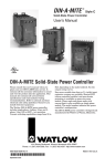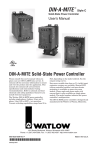
1
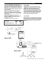
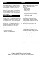
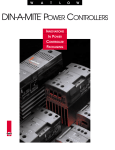
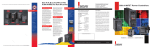
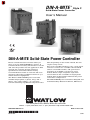
DIN-A-MITE
®
Style C
Solid-State Power Controller
User’s Manual
C
US
LISTED
DIN-A-MITE Solid-State Power Controller
Please consult this user’s manual when you
place your new DIN-A-MITE into service. It
contains all the necessary information to mount
and wire the product into the application. This
manual also contains all user-pertinent
specifications and semiconductor fusing
recommendations. Refer to national and local
electrical code safety guidelines whenever you
install electrical equipment.
The Watlow DIN-A-MITE power controller
includes single-phase, 3-phase, 2-leg, and 3phase, 3-leg, 120 to 600 VÅ (ac) operation.
Current switching capabilities range from 30 to
80 A, depending on the model ordered. See the
output rating curves.
Zero-cross variable time base or Vı (ac/dc) input
contactor versions are available. Shorted SCR
(silicon controlled rectifier) and open-heater
protection is available on some zero-cross
models. Phase angle and phase angle with
current limit is also available on single-phase
models. The model number indicates the power
controller’s configuration.
The DIN-A-MITE power controller is designed and
manufactured by Watlow in Winona, Minnesota.
1241 Bundy Boulevard, Winona, Minnesota USA 55987
Phone: +1 (507) 454-5300, Fax: +1 (507) 452-4507 http://www.watlow.com
0600-0025-0009 Rev G
March 2003
Made in the U.S.A.
$5.00
General Specifications
(2365)
Operator Interface
• Command signal input and indication light
• Alarm output and indication light
• Current limit indication LED
Amperage Rating
See the output rating curve chart on page 5 for all
the natural convection, fan-cooled, and throughwall mount models.
Ratings are into a resistive heater load
• Maximum surge current for 16.6 milliseconds, 1,350 A
peak
• Maximum I2t for fusing is 9100 A2s
• Latching current: 500 mA minimum
• Holding current: 200 mA minimum
• Fan current: 0.14 A for 24 VÎ (dc); 0.12 A for 120 V~
(ac); 0.06 A for 240 V~ (ac)
• Off-state leakage 1 mA at 25°C (77°F) maximum
Line Voltage
• 24 to 48 V~ (ac) units: 20 V~ minimum to 53 V~
maximum
• 100 to 240 V~ (ac) units: 48 V~ minimum to 265 V~
maximum
• 277 to 600 V~ (ac) units: 85 V~ minimum to 660 V~
maximum
• 100 to 120 V~ (ac), 200 to 208 V~, 230 to 240 V~, 277
V~, 400 V~, 480 V~, 600 V~, -15%/+10%, 50 or 60
Hz independent +/-5% (Input Control Signal Type L, P
and S)
Alarms (zero cross models only)
Shorted SCR Alarm Option
• Alarm state when the input command signal is off and
a 10 A or more load current is detected by the current
transformer (two turns required for 5 A or three turns
for 2.5 A).
Open Heater Alarm Option
• Alarm state when the input command signal is on and
the load current detected by the current transformer is
less than the alarm set point. Available with Input
Control Signal option S only.
Alarm Output
• Energizes on alarm, non-latching
• Triac 24 to 240 V~ (ac), external supply with a current
rating of 300 mA @ 25°C (77°F), 200 mA @ 50°C
(122°F), 100 mA @ 80°C (176°F) and a holding current
of 200 µA with a latching current of 5 mA typical.
2
WATLOW DIN-A-MITE Style C User's Manual
• Agency Approvals
• CE with proper filter:
89/336/EEC Electromagnetic Compatibility Directive
EN 61326: Industrial Immunity Class A emissions
Not suitable for Class B environments.
73/23/EEC Low Voltage Directive
EN 50178 Safety Requirements
Installation category III, Pollution degree 2
Phase angle and phase angle with current limit Input
Control Signal Types (P and L) are not CE approved.
• UL® 50 Type 4X Enclosure and UL® 1604 File E184390
(Through-wall heatsink mounting only)
•
UL® 508 listed and C-UL®, File E73741
C
US
LISTED
Input Terminals
• Compression: Will accept 0.2 to 2 mm2 (24 to 14
AWG) wire
• Torque to 0.5 Nm (4.4 in-lb) with a 3.5 mm (1/8 in)
blade screwdriver
• Wire strip length 5.5 mm (0.22 in)
Line, Load and Ground Terminals
• Compression: Will accept 2 to 21 mm2 (14 to 4 AWG)
wire
• Torque to 2.7 Nm (24 in-lb) with a 6.4 mm (1/4 in)
blade screwdriver, or a No. 2 Phillips screwdriver
• Wire strip length 11 mm (7/16 in)
Operating Environment
• See the output rating curve chart on page 5.
• 0 to 90% RH (relative humidity), non-condensing
• Storage temperature: -40 to +85°C (-40 to 185°F)
• Insulation only tested to 3,000 meters
DIN Rail Mount
• DIN EN 50022, 35 mm by 7.5 mm
• Minimum clipping distance: 34.8 mm (1.37 in)
• Maximum clipping distance: 35.3 mm (1.39 in)
Back Panel Mount
• Four mounting holes M3 to M4 (No. 6 to No. 8)
fastener
Through-Wall Mount
• See page 8 for through-wall cutout
Weight
• 1.0 to 1.9 kg (2.2 to 4.2 lb) depending upon model
Specifications are subject to change without notice.
Additional Specifications for Contactors and Proportional Controls
Control Mode, Zero-Cross
• Input Control Signal Type C: VÎ (dc) input contactor.
To increase service life, the cycle time should be less
than 3 seconds.
• Input Control Signal Type K: V~ (ac) input contactor.
To increase service life, the cycle time should be less
than 3 seconds.
• Input Control Signal Type F: 4 to 20 mAÎ (dc)
proportional variable time base control.
Input Command Signal
• AC contactor
24 VÅ ±10%, 120 VÅ +10%/-25%, 240 VÅ (ac)
+10%/-25% @ 25 mA maximum per controlled leg
• DC Contactor
4.5 VÎ to 32 VÎ (dc): maximum current @ 4.5 VÎ
(dc) is 6 mA per leg. Add 2 mA per LED used to the
total current.
• Loop powered linear current
4 mAÎ to 20 mAÎ (dc): loop-powered. Input Type
F0 option only. (Requires current source with 6.2
VÎ (dc) available. No more than three
inputs connected in series)
Linearity (Input Control Signal Type F)
• Full on point 19.5 to 19.9 mAÎ (dc), maximum voltage
of 6.2 V peak.
• ±5% input to output power accuracy, 0% to 100% of
span (4.3 to 19.7 mA or 12.3 to 19.7 mA).
• Temperature stability is less than 0.15%/°C change.
Additional Specifications: Phase Angle; Phase Angle Current Limit; & Single Cycle VTB
Operation
• Burst firing (zero-cross) control, single-cycle variable
time base, Type S single-phase and 3-phase. Unit is
not on for more than one full cycle under 50% power
and not off for more than one full cycle above 50%
power.
• Phase angle control, single-phase only
Input Command Signal
• 0 to 20 mA, 4 to 20 mA, 12 to 20 mA, Î (dc), 0 to 5
VÎ, 1 to 5 VÎ, and 0 to 10 VÎ
• Input impedance 250 Ω for 4 mA to 20 mA, 5 kΩ for
linear voltage input
Output Voltage
• 100 to 120 V~ (ac), 200 to 208 V~, 230 to 240 V~, 277
V~, 400 V~, 480 V~ and 600 V~, ±10%
Linearity (Input Control Signal Type S)
• ±5% input to output power over 0% to 100% of span
between calibration points
Linearity (Phase Angle Input Control Type P and L)
• ±5% input to output power, as referenced to a
sinusoidal power curve, between calibration points
Soft Start
(Phase Angle Input Control Signal Type P and L)
Typically:
• 5 seconds soft start on power up
• Soft start on thermostat overtemperature
• Soft start on 1/2 cycle drop out detection
• 1 second soft switching on set point change
Options
• Manual Control Kit (1 kΩ potentiometer) 08-5362
• Alarm option is not available on phase angle Type P or
L
Resolution
• Better than 0.1% of input span with respect to output
change
WATLOW DIN-A-MITE Style C User's Manual
3
DIN-A-MITE C Ordering Information (2366)
To order, complete the code number on the right with the information below:
D __
C __ __ - __ __ __ __ - __ __ __ __
__
Style C solid-state power controller
Phase
1 = single-phase, 1 controlled leg
2 = 3-phase, 2 controlled legs
3 = 3-phase, 3 controlled legs (use with four wire wye)
8 = 2 independent zones (input control C, K)
9 = 3 independent zones (input control C, K)
Current Rating Table
Phase Cooling Current
at 50°C
Cooling and Current Rating Per Leg
0 = Natural convection standard DIN rail or panel heatsink
1 = Fan-cooled 120 V~ (ac) standard DIN rail or panel heatsink
2 = Fan-cooled 240 V~ (ac) standard DIN rail or panel heatsink
3 = Fan-cooled 24 VÎ (dc) fan standard DIN rail or panel heatsink
T = Natural convection through-wall or cabinet heatsink (UL 50)
1
1
1
2, 8
2, 8
2, 8
3, 9
3, 9
3, 9
Line and Load Voltage
02 = 24 to 48 V~ (ac) (Input Control Signal C, F, or K only)
12 = 100 to 120 V~ (ac) (Input Control Signal L, P or S only)
20 = 200 to 208 V~ (ac) (Input Control Signal L, P or S only)
24 = 120 to 240 V~ (ac) (Input Control Signal C, F or K only);
230 to 240 V~ (ac) (Input Control Signal L, P or S only)
27 = 277 V~ (ac) (Input Control Signal L, P or S only)
40 = 400 V~ (ac) (Input Control Signal L, P or S only)
48 = 480 V~ (ac) (Input Control Signal L, P or S only)
60 = 277 to 600 V~ (ac) (Input Control Signal C, F or K only);
600 V~ (ac) (Input Control Signal L, P or S only)
Input Control Signal
C0 = 4.5 to 32 VÎ (dc) contactor
K1 = 22 to 26 V~ contactor
K2 = 100 to 120 V~ contactor
K3 = 200 to 240 V~ contactor
F( )=Proportional
0 = 4 to 20 mA
L(0 to 5) = Phase angle with current limiting (DC1 only, Alarm 0 only,
includes one current transformer - Single phase only)
P(0 to 5) = Phase angle (DC1 only, Alarm 0 only - Single phase only)
S(0 to 5) = Single-cycle variable time base
(Select one of the gollowing input options for L, P, S, (0-5))
0 = 4 to 20 mA
1 = 12 to 20 mA
2 = 0 to 20 mA
3 = 0 to 5 VÎ (dc) proportional
4 = 1 to 5 VÎ (dc) proportional
5 = 0 to 10 VÎ (dc) proportional
Alarm
0 = No alarm
S = Shorted-SCR alarm
H = Open-heater and shorted-SCR alarm (for Input Control Signal option S only)
User Manual Language
0 = English
1 = German
2 = Spanish
3 = French
Custom Part Numbers
00 = Standard part
1X = 1-second soft start (control option P, L)
XX = Any letter or number, custom options, labeling, etc.
Recommended semiconductor fuse for applications through 600 VÅ (ac):
Fuse part number
DIN-A-MITE
Model
30 A
35 to 40 A
45 to 50 A
55 to 65 A
75 A
4
Fuse Holder part number
Watlow
Bussmann
Ferraz
17-8040
17-8050
17-8063
17-8080
17-8100
FWP-40A14F
FWP-50A14F
FWP-63A22F
FWP-80A22F
FWP-100A22F
A093909
B093910
T094823
A094829
Y094827
WATLOW DIN-A-MITE Style C User's Manual
DIN-A-MITE
Model
30 A
35 to 40 A
45 to 50 A
55 to 65 A
75 A
Watlow
Ferraz
17-5114
17-5114
17-5122
17-5122
17-5122
PFZ-J081221
PFZ-J081221
PFZ-F220368
PFZ-F220368
PFZ-F220368
0
T
1, 2, 3
0
T
1, 2, 3
0
T
1, 2, 3
55 A
60 A
75 A
40 A
45 A
65 A
30 A
35 A
55 A
Extended Heater And SCR Life
With Variable Time Base
Models: DC _ _ -[02, 24, 60] [F0, F1]- _ _ _ _
DIN-A-MITE Style C Ratings at 100% On
90
20% Power, 3 AC line cycles on, 12 cycles off
85
Natural Convection
80
75
50% Power, 3 AC line cycles on, 3 cycles off
70
65
Si
as
e
eg
2-l
40
se,
45
ha
leg
, 3ase
50
3-p
55
ph
le-
ng
60
h
3-p
Maximum Internal Enclosure Ambient Temperature (°C)
Output Rating Curves
35
30
25
0
5 10 15 20 25 30 35 40 45 50 55 60 65 70 75 80
DIN-A-MITE Style C Ratings at 100% On
Single-Cycle Variable Time Base
Models: DC _ _ - _ _ S _ - _ _ _ _
80
75
70
25% Power, 1 AC line cycle on, 3 cycles off
65
as
ase
50% Power, 1 AC line cycle on, 1 cycle off
g
g
le
le
3-
40
2-
e,
e,
as
45
-ph
ph
ph
50
gle
Sin
3-
55
35
30
25
0
5 10 15 20 25 30 35 40 45 50 55 60 65 70 75 80 85 90
Current (Amps) into a Resistive Load
DIN-A-MITE Style C Ratings at 100% On
80
Recommended maximum
enclosure temperature is 80 C (176 F)
75
With single-cycle variable time base (VTBS)
control, at 50% power, power is on one cycle, and
off one cycle. At 25%, it is on for one cycle and
off for three. Under 50%, the unit is not on for
more than one consecutive cycle. Over 50%, the
unit is not off for more than one consecutive
cycle. This model will work with a linear voltage
input, a 4 to 20 mA input or a potentiometer
input.
70
65
Si
Through-Wall Heatsink
ng
60
3ph
Phase Angle
Models: DC1 _ - _ _ [L, P] _ - 0 _ _ _
g
-le
g
-le
,3
40
,2
se
45
e
as
ha
50
e
as
ph
le-
55
3- p
Ambient Air Around Heatsink Fins ( C)
∫6
Fan-Cooled
60
3-
Maximum Internal Enclosure Ambient Temperature (°C)
Current (Amps) into a Resistive Load
With variable time base control, the power
controller automatically adjusts the time base
and output power with respect to process input.
Accelerated life testing verified that the variable
time base control significantly reduces
expansion and contraction of the heater element.
This extends heater and SCR life while
improving the process temperature control. You
save money on heaters, down time and
maintenance.
35
30
25
0
5 10 15 20 25 30 35 40 45 50 55 60 65 70 75 80
Current (Amps) into a Resistive Load
Phase angle control (control Type P) is infinitely
variable inside the sine wave. This provides a
variable voltage and/or current output. This
option includes soft start and line voltage
compensation. This model will work with a linear
voltage input, a linear current source input or a
potentiometer input. This is single-phase only.
Alarms not available on phase angle models.
WATLOW DIN-A-MITE Style C User's Manual
5
Mount
Dismount
4
1
3
2
1
1. Push the unit in and down to catch the rail
hook on top of the rail.
1. Press down on the release tab while rotating
the unit up and away from the rail.
2. Rotate the bottom of the unit in toward the
rail.
3. The rail clasp will audibly “snap” into place.
If the DIN-A-MITE does not snap into place,
check to see if the rail is bent.
4. Mount the cooling fins vertically.
ç3
WARNING:
Only authorized and
qualified personnel
should be allowed to
install and perform
preventive and corrective
maintenance on this unit.
Failure to follow this
guideline could result in
damage to equipment,
and personal injury or
death.
Unit Dimensions - Fan-Cooled
Side 102 mm (4.0 in) clearance for air flow and wire bending radius
146 mm (5.74 in)
102 mm (4.0 in)
142 mm (5.59 in)
44 mm
(1.73 in)
131 mm
(5.17 in)
79 mm
(3.10 in)
5
WARNING:
Hot surface, do not touch
the heat sink. Failure to
follow this guideline
could result in personal
injury.
127 mm 182 mm
(5.00 in) (7.16 in)
Rail Release Tab
(pull down)
Front panel is touch-safe,
no clearance is required.
102 mm (4.0 in) minimum
102 mm (4.0 in) clearance for air flow and wire bending radius
ç
Mount the cooling fins
vertically.
6
57 mm
(2.26 in)
150 mm
(5.89 in)
WATLOW DIN-A-MITE Style C User's Manual
ç
∫3
5
ç
∫3
Unit Dimensions - Rail-Mounted
Top
WARNING:
Only authorized and
qualified personnel
should be allowed to
install and perform
preventive and corrective
maintenance on this unit.
Failure to follow this
guideline could result in
damage to equipment,
and personal injury or
death.
5
WARNING:
Hot surface, do not touch
the heat sink. Failure to
follow this guideline
could result in personal
injury.
146 mm
(5.74 in)
5
Ground
wire
entry
83 mm
(3.25 in)
Side 102 mm (4.0 in) clearance for air flow and wire bending radius
146 mm (5.74 in)
102 mm (4.0 in)
142 mm (5.59 in)
44 mm
(1.73 in)
131 mm
(5.17 in)
57 mm
(2.26 in)
150 mm
(5.89 in)
79 mm
(3.10 in)
ç
Mount the cooling fins
vertically.
ç
∫3
Rail Release Tab
(pull down)
127 mm
(5.00 in)
102 mm (4.0 in) minimum
102 mm (4.0 in) clearance for air flow and wire bending radius
Front panel is touch-safe, no clearance is required.
Front
38 mm (1.51 in)
46 mm (1.81 in)
54 mm (2.11 in)
Allowance for M4
(#8 Fastener)
1
2
3
138 mm
(5.45 in)
DIN-EN 50022
35 by 7.5 mm rail
(clipping distance =
34.7 to 35.3 mm
[1.366 to 1.390 in])
87 mm
(3.42 in)
4
5
6
48 mm
(1.89 in)
Allowance for M4
(#8 Fastener)
WATLOW DIN-A-MITE Style C User's Manual
7
Mounting
Mounting procedure
for UL® 50 Type 4X
Enclosure and UL®
1604 Through-wall
mount models
Materials included:
(1) Silicone gasket
(8) M5 screws and
lockwashers
(1) DIN-A-MITE C
through-wall
Unit Dimensions - Through-Wall (Cabinet Panel)
ç
∫3
Top
3. Peel off the
protective film from
the silicone
gasket. Stick the
gasket to the
heatsink so the
gasket holes line
up with the screw
holes in the
heatsink.
114 mm
(4.50 in)
55 mm (2.17 in)
inside
(12 gauge)
Front panel is touch-safe,
no clearance is required.
Sheet Metal (12 gauge)
1. Drill and cut the
panel as shown in
the dimensioned
drawing at right.
2. Remove the
mounting screws
from the heatsink.
5
57 mm (2.25 in)
outside
(any gauge)
Front
M5 (0.8 by 10 mm) (8)
M5 Internal Tooth Lock Washer (8)
included
122 mm (4.81 in)
102 mm (4.0 in) minimum
clearance for air flow
(top and bottom)
Ground lug (2-8 GA)
1
Panel
Opening
Outline
2
3
178 mm (7.00 in)
4. Mount the heatsink
vertically. Torque
to 2.26 to 2.82 Nm
(20 to 25 in-lb).
4
5
6
10 mm (0.4 in) minimum
clearance for air flow
(both sides)
Drill 5.8 mm (0.228 in) (8)
Typical Panel Opening
Heatsink Outline
9.5 mm (0.375 in) Reference
10.8 mm (0.425 in)
41.3 mm
(1.625 in)
117.5 mm
(4.625 in)
161.9 mm
(6.375 in)
148.6 mm
(5.850 in)
8.6 mm (0.338 in) Reference
7.0 mm (0.275 in)
26.3 mm (1.034 in)
78.8 mm
(3.103 in)
98.1 mm
(3.862 in)
105.1 mm
(4.137 in)
8
WATLOW DIN-A-MITE Style C User's Manual
ç
∫1
Input Wiring
(For models DC [1, 2, 3] _ - _ _ [C, F, K] _ - _ _ _ _)
1
WARNING:
Use National Electric (NEC)
or other country-specific
standard wiring practices to
install and operate the DINA-MITE. Failure to do so may
result in damage to
equipment and property,
and/or injury or loss of life.
3
∫
WARNING:
Only authorized and qualified
personnel should be allowed
to install and perform
preventive and corrective
maintenance on this unit.
Failure to follow this
guideline could result in
damage to equipment, and
personal injury or death.
NOTE:
Alarm options not available
with multizone input option.
7 +
8 9
10
11
12
13
14
15
16
17
18
19
20
VÅ (ac) Input:
4 to 20 mAÎ (dc) Input:
4.5 to 32 VÎ (dc) Input:
+
+
-
7
8
9
+
-
7
8
9
+
-
2
ç
∫1
∫3
3
Gain
Adjustment
Potentiometers
Bias
Open
Heater
Limit
Signal
Alarm
Zone
1
Zone
2
Zone
3
4
5
6
Multizone Input Wiring
(For models DC [8, 9] _ - _ _ _0 - 0 _ _ _)
1
2
3
2-zone
Zone 1 VÎ (dc) Input: +
-
Zone 2 VÎ (dc) Input: +
-
Zone 1
V~ (ac) Input:
Zone 2 V~ (ac) Input:
7 +
8 9
10
11
12
13
7 +
8 9
10
11 +
12 13
14
15
16
17
18
19
20
Gain
Adjustment
Potentiometers
Limit
Signal
Zone
1
4
3-zone
1
Zone 1 VÎ (dc) Input:
Zone 2 VÎ (dc) Input:
Zone 3 VÎ (dc) Input:
Zone 1 V~ (ac) Input:
Zone 2 V~ (ac) Input:
Zone 3 V~ (ac) Input:
7 +
8 9
10
11
12
13
+
+
+
-
7 +
8 9 +
10 11 +
12 13
14
15
16
17
18
19
20
Bias
Open
Heater
Alarm
Zone
2
Zone
3
5
6
2
ç
∫1
∫3
3
Gain
Adjustment
Potentiometers
Bias
Open
Heater
Limit
Signal
Alarm
Zone
1
Zone
2
Zone
3
4
5
6
WATLOW DIN-A-MITE Style C User's Manual
9
ç
NOTE:
The potentiometer is
customer-supplied. For
the potentiometer only,
order Watlow part
number 08-5362.
Input Wiring
(For models DC [1, 2, 3] _ - _ _ [L, P, S] _ - _ _ _ _)
4 to 20 mA and Linear Voltage Input
1
2
3
Counterclockwise
1 kΩ
Potentiometer
Clockwise
1 kΩ Potentiometer Input
Use with 0 to 5VÎ (dc) Input
4 to 20 mAÎ (dc) Input
+
-
Linear voltage VÎ (dc) Input
7
8
9
+
-
7 +
8 9 CW
10
11
12
13
14
15
16
17
18
19
20
Gain
Open
Heater
Limit
Signal
Alarm
Zone
1
Zone
2
Zone
3
4
5
6
1
2
3
+
-
7 +
8 9
10
11
12
13
14
15
16
17
18
19
20
Bias
Adjustment
Potentiometers
ç
∫1
∫3
Gain
Bias
Adjustment
Potentiometers
Open
Heater
Limit
Signal
Alarm
Zone
1
Zone
2
Zone
3
4
5
6
Auto and Manual Input Application
(For models DC [1, 2, 3] _ - _ _ [L, P, S] [3, 4] - _ _ _ _
When you use the 4 to 20 mAÎ (dc) temperature
controller output and the DIN-A-MITE control
input 1 to 5VÎ (dc).
Counterclockwise
4 to 20 mA Î
250
Ω
200 Ω resistor
(dc) signal
from the
Auto
+
temperature
controller
1 kΩ
Manual
Potentiometer
1
2
3
-
NOTE:
The potentiometer and
resistors are customersupplied. For the
potentiometer control
assembly only, order
Watlow part number 085362.
Clockwise
If you use the 0 to 5 VÎ (dc) temperature controller
output, order the DIN-A-MITE control input
0 to 5 VÎ (dc).
Counterclockwise
0 to 5 VÎ (dc)
signal
Auto
from the
temperature
1 kΩ
controller
Manual
Potentiometer
Clockwise
10
WATLOW DIN-A-MITE Style C User's Manual
7 +
8 9 CW
10
11
12
13
14
15
16
17
18
19
20
7 +
8 9 CW
Gain
Adjustment
Potentiometers
Bias
Open
Heater
Limit
Signal
Alarm
Zone
1
Zone
2
Zone
3
4
5
6
ç
∫1
∫3
∫1
WARNING:
Use National Electric (NEC)
or other country-specific
standard wiring practices to
install and operate the DINA-MITE. Failure to do so may
result in damage to
equipment and property,
and/or injury or loss of life.
Input Wiring Phase Angle with Current Limit
(Model DC1 _ - _ _ L [0, 1, 2, 3, 4, 5] - _ _ _ _ )
Linear current and linear voltage input
1
Input Signal:
2
∫
WARNING: Wiring examples
show L2 in phase-to-phase,
200 VÅ (ac) and above
configuration. In phase-toneutral, 100 VÅ (ac) and
above applications, L2 is
neutral and must not be
fused or switched. Failure to
follow this guideline could
result in personal injury or
death.
∫3
WARNING:
Only authorized and qualified
personnel should be allowed
to install and perform
preventive and corrective
maintenance on this unit.
Failure to follow this
guideline could result in
damage to equipment, and
personal injury or death.
NOTE:
The alarm options are not
available with phase angle
units.
Current
Transformer
(CT)
+
-
7
8
9
10
11
12
13
14
15
16
17
18
19
20
2
ç
∫1
3
+
Gain
Adjustment
Potentiometers
Bias
Open
Heater
CT1
CT1
Limit
Signal
Zone
1
4
Alarm
Zone
2
5
Zone
3
Zone 3 is the
current limit
indicator in
phase angle
current limit
models.
6
Load Wire
Heater
Current Limit Adjustment Procedure
The DC1 _ - _ _ L _ - 0 _ _ _ model is a phase angle controller that can
limit the maximum current to the load. A potentiometer on the DIN-AMITE adjusts the current limit setting. Use the following steps to
adjust the current limit on initial setup. The purpose of the procedure
is to bring the power to the load slowly so that the desired maximum
current to the load is not exceeded before the current limit is adjusted.
NOTE: The DIN-A-MITE is shipped factory-calibrated with the potentiometer
adjusted fully clockwise (no current limiting). Adjust the potentiometer clockwise
to increase the current; counterclockwise to decrease the current.
NOTE: A short overcurrent through the load may occur, as the circuitry detects the
high current, if the input signal from the temperature controller is abruptly
increased.
1. Attach a clamp-on ammeter to the load line.
2. Adjust the current limit potentiometer fully counterclockwise (for
minimum current flow).
3. Turn the temperature controller on and adjust the input signal to
the DIN-A-MITE for zero percent power.
4. Turn on the power to the DIN-A-MITE.
5. Gradually increase the input signal.
6. Adjust the current limit potentiometer clockwise until the current to
the load is measurable. The current limit indicator (Zone 3) light
should turn on until the output is allowed to go full on, with no
limit. At that point, the indicator light will turn off.
7. Gradually increase the input signal to 100% power, then adjust the
current limit potentiometer to obtain the desired maximum current
to the load.
WATLOW DIN-A-MITE Style C User's Manual
11
Single-phase Alarm
Non-latching Alarm Option
DC _ _ - _ _ _ _ - [H, S] _ _ _
NOTE:
If you plan to wire
multiple DIN-A-MITE
alarm outputs, you
need to include an
intermediate relay for
each DIN-A-MITE used.
V~
120 or 240 V~
@ 300 mA maximum
energizes on alarm
1
7
8
9
10
11
12
13
14
15
16
17
18
19
20
Alarm Relay
or Indicator
1A
Current
Transformer
(CT)
+
+
+
-
2
Triac
Gain
Open
Heater
ALM
CT1
ALM = Alarm
CT = Current Transformer
CT2
CT2
Bias
Adjustment
Potentiometers
ALM
CT1
ç
∫1
∫3
3
Signal
Limit
Alarm
CT3
CT3
Zone
1
4
Zone
2
Zone
3
5
6
Load Wire
Heater
The Watlow DIN-A-MITE alarm option provides
a common alarm output for open-heater or
shorted SCR conditions. This is a non-latching
alarm.
• A shorted SCR alarm is detected when there is
no command signal and a load current is
detected. The alarm output is then energized.
• An open-heater or partial open-heater state is
detected when a command signal is present and
a reduced or no output current is detected. The
alarm output is then energized.
Load Current
Passes of Load
Wire Through the
Current Transformer
5 to 9 A
10 to 65 A
Setup Procedure for Open-Heater Alarm
(For Input Control Signal type S option only)
1. With the temperature control wired to the
DIN-A-MITE SCR power control, set the
temperature control output to “full on” (20 mA
for 4 to 20 mA output, or 5 V for 0 to 5 V output).
2. Adjust the open heater alarm adjustment
potentiometer until the alarm indicator light on
the front panel is full on, with no intermittent
cycling.
3. Slowly adjust the potentiometer until the
open heater indicator light just turns full off,
with no intermittent cycling.
If you are getting false alarms, the adjustment is
probably set too sensitive and should be readjusted towards the off condition of the openheater indicator light.
2
1
No setup procedure required for shorted SCR alarm.
3-phase, 2-leg Open Heater Alarm
(Model DC2 _ - _ _ S _ - H _ _ _ )
1
7
8
9
10
11
12
13
14
15
16
17
18
19
20
+
+
+
-
2
Adjustment
Potentiometers
CT1
ALM = Alarm
CT = Current Transformer
CT1
Open
Heater
Limit
CT2
CT2
Gain
Bias
ALM
ALM
ç
∫1
∫3
3
Signal
Alarm
CT3
CT3
Zone
1
Zone
2
Zone
3
4
5
6
T3
NOTE:
Load wires must pass
through each current
transformer in the same
direction.
white
T2
black
Current Transformers
12
WATLOW DIN-A-MITE Style C User's Manual
Heater
T1
ç
NOTE:
Adjust the potentiometer
clockwise to increase the
current; counterclockwise to
decrease the current.
3-phase, 2-leg Shorted SCR Alarm
(Model DC2 _ - _ _ [C, F, K, S] _ - S _ _ _ )
1
7
8
9
10
11
12
13
14
15
16
17
18
19
20
∫1
WARNING:
Use National Electric (NEC)
or other country-specific
standard wiring practices to
install and operate the DINA-MITE. Failure to do so may
result in damage to
equipment and property,
and/or injury or loss of life.
+
+
+
-
2
Adjustment
Potentiometers
CT1
Gain
Bias
ALM
ALM
ç
∫1
∫3
3
ALM = Alarm
CT = Current Transformer
CT1
Open
Heater
Limit
CT2
CT2
CT3
CT3
Signal
Alarm
Zone
1
Zone
2
Zone
3
4
5
6
T3
Heater
T2
3
T1
∫
WARNING:
Only authorized and qualified
personnel should be allowed
to install and perform
preventive and corrective
maintenance on this unit.
Failure to follow this
guideline could result in
damage to equipment, and
personal injury or death.
3-phase, 3-leg Alarm, Shorted SCR and Open Heater Alarm
(Model DC3 _ - _ _ _ _ - S _ _ _ )
1
CT
NOTE:
The shorted SCR alarm
option is not available with
phase angle units.
7
8
9
10
11
12
13
14
15
16
17
18
19
20
+
+
+
-
2
Adjustment
Potentiometers
CT1
Gain
Bias
ALM
ALM
ç
∫1
∫3
3
ALM = Alarm
CT = Current Transformer
CT1
Open
Heater
Limit
CT2
CT2
Signal
Alarm
CT3
CT3
Zone
1
Zone
2
Zone
3
4
5
6
T3
Neutral
white
black
white
black
Heater
T1
T2
white
Current
Transformers (CT)
Fan-Cooled
1
7
8
9
10
11
12
13
14
15
16
17
18
19
20
Fan power required
24 VÎ (dc)
120 V~ (ac)
240 V~ (ac)
(customer supplied)
24 VÎ (dc)
Red wire (+)
Black wire (-)
Phase to neutral
100 VÅ (ac)
and above
L1
L2
Phase to phase
200 VÅ (ac)
and above
2
3
+
Gain
Adjustment
Potentiometers
Bias
ç
∫1
∫3
Open
Heater
CT1
CT1
Limit
Signal
Alarm
Zone
1
Zone
2
Zone
3
4
5
6
L1
L2
WATLOW DIN-A-MITE Style C User's Manual
13
∫2
WARNING:
Wiring examples show L2
in phase-to-phase, 200
VÅ (ac) and above
configuration. In phaseto-neutral, 100 VÅ (ac)
and above applications,
L2 is neutral and must not
be fused or switched.
Failure to follow this
guideline could result in
personal injury or death.
∫3
WARNING:
Only authorized and
qualified personnel
should be allowed to
install and perform
preventive and corrective
maintenance on this unit.
Failure to follow this
guideline could result in
damage to equipment,
and personal injury or
death.
(Model DC1 _ - _ _ _ _ - _ _ _ _ )
Limit Control
Contacts
(if required)
1
7
8
9
10
11
12
13
14
15
16
17
18
19
20
2
+
+
+
ALM
L1
L1
L2
Neutral
ç
∫1
∫2
∫3
3
Gain
ALM
Phase-to-neutral
100V~ (ac)
and above
Phase-to-phase
200V~ (ac)
and above
Semiconductor Fuse
Internal Busbar
WARNING:
Use National Electric
(NEC) or other countryspecific standard wiring
practices to install and
operate the DIN-A-MITE.
Failure to do so may
result in damage to
equipment and property,
and/or injury or loss of
life.
Single-phase Output
Adjustment
Potentiometers
Bias
Open
Heater
CT1
CT1
Limit
CT2
CT2
Signal
Alarm
CT3
CT3
Zone
1
Zone
2
Zone
3
4
5
6
Heater
3-phase, 2-leg Output
(Model DC2 _ - _ _ _ _ - _ _ _ _ )
ç
∫1
∫2
∫3
Semiconductor Fuses
L1
L2
L3
1
7
8
9
10
11
12
13
14
15
16
17
18
19
20
+
+
+
-
2
Gain
ALM
ALM
CT1
Adjustment
Potentiometers
Bias
Open
Heater
CT1
Limit
CT2
CT2
Limit Control
Contacts
(if required)
3
Internal Busbar
ç
∫1
Signal
Alarm
CT3
CT3
Zone
1
Zone
2
Zone
3
4
5
6
T3
T2
14
WATLOW DIN-A-MITE Style C User's Manual
Heater
T1
3-phase, 3-leg Output, Four Wire Wye
ç
∫1
∫2
∫3
(Model DC3 _ - _ _ _ _ - _ _ _ _ )
Semiconductor Fuses
L1
L2
L3
1
7
8
9
10
11
12
13
14
15
16
17
18
19
20
2
3
+
+
+
-
Limit Control
Contacts
(if required)
Gain
Adjustment
Potentiometers
Bias
ALM
Open
Heater
ALM
CT1
CT1
Limit
CT2
CT2
Signal
Alarm
CT3
CT3
Zone
1
Zone
2
Zone
3
4
5
6
Neutral
Heater
Multizone Output Wiring
(For models DC [8, 9] _ - _ _ [C, K] _ - _ _ _ _
2-zone
Line
Voltage
L1
Semiconductor
Fuses
3-zone
Semiconductor
Fuses
Line
Voltage
L1
L1
L1
1
7
8
9
10
11
12
13
14
15
16
17
18
19
20
2
Limit Control
Contacts
(if required)
3
+
+
+
-
Gain
Bias
ALM
Open
Heater
ALM
CT1
CT1
Limit
CT2
CT2
Alarm
Signal
CT3
CT3
Zone
1
Zone
2
Zone
3
4
5
6
L1
2 Independent,
Single-Phase
Heaters
∫1
∫2
∫3
1
7
8
9
10
11
12
13
14
15
16
17
18
19
20
2
+
+
+
-
Gain
Bias
ALM
Open
Heater
ALM
CT1
CT1
Limit
CT2
CT2
Signal
Alarm
CT3
CT3
Zone
1
Zone
2
Zone
3
4
5
6
Heater
1
Heater Heater
2
3
Heater 1
Heater 2
L2
L2
Limit Control
Contacts
(if required)
3
L2
NOTE:
Independent loads do
not have to be on the
same phase.
3 Independent,
Single-Phase Heaters
L2
L2
WATLOW DIN-A-MITE Style C User's Manual
15
ç
∫1
System Wiring Example
WARNING:
Use National Electric
(NEC) or other countryspecific standard wiring
practices to install and
operate the DIN-A-MITE.
Failure to do so may
result in damage to
equipment and property,
and/or injury or loss of
life.
L3
480 VÅ
(ac)
L2
L1
Breaker
480 V~ (ac)
120 V~ (ac)
∫2
WARNING:
Wiring examples show L2
in phase-to-phase, 200
VÅ (ac) and above
configuration. In phase-toneutral, 100 VÅ (ac) and
above applications, L2 is
neutral and must not be
fused or switched. Failure
to follow this guideline
could result in personal
injury or death.
93BB-1FA0-00RR
11 12
+ 3
Series 9
93
– 5
10
Controller
Thermocouple
16
146E-1601-3000
3
LP1
Alarm
OverTemperature
∫
NOTE: If you plan to wire
multiple DIN-A-MITE
alarm outputs, you need to
include an intermediate
relay for each DIN-A-MITE
used.
–
1
3
WARNING:
Only authorized and
qualified personnel should
be allowed to install and
perform preventive and
corrective maintenance on
this unit. Failure to follow
this guideline could result
in damage to equipment,
and personal injury or
death.
+
Series 146
High Limit
9 Normally closed
CR1
Coil
AC Common
CR1 = High-Limit Contactor
7 Normally open
5 13 14 10 11
+ –
AC High
Reset
High Limit
Thermocouple
Alternative Latching Alarm Circuit
If there is a need for a latching alarm in the case of an open heater or
shorted SCR, the DIN-A-MITE alarm circuit could be used as shown in the
latching alarm example at right. If the DIN-A-MITE triac alarm output
energizes, it will energize the RY1 (external alarm relay) mechanical relay
coil. Once the RY1 coil is energized it will latch on (via the RY1A normally
open contact) until the power to the relay is removed. You could cycle the
power via a reset switch. The RY1B contact set can be used for alarm
signaling.
WATLOW DIN-A-MITE Style C User's Manual
Ungrounded Delta or Wye Load
3-phase, 2-leg DIN-A-MITE
Non-latching Alarm Option
(models DC_ _ - _ _ S _ - H _ _ _ )
Open Heater and Shorted SCR Alarm
The shorted SCR detector compares the input
command signal and actual load current. If
load current is present without an input signal
then the shorted SCR alarm will energize a
triac (on board the DIN-A-MITE) output.
CR1
An open-heater or partial open-heater state is
detected when a command signal is present
and a reduced or no output current is detected.
The alarm output is then energized.
Semiconductor
Fuses
1
2
3
This is a non-latching alarm. This output can
be used to drive various indication devices,
such as a coil, light, buzzer, etc. See the
alternative latching circuit section below.
Signal
Alarm Relay
or Indicator
V~
(ac)
1A
120 or 240 V~ (ac)
@ 300 mA maximum
energizes on alarm
7 +
8 9 +
10 11 +
12 13 ALM
14 ALM
15 CT1
16 CT1
17 CT2
18 CT2
19 CT3
20 CT3
Gain
Adjustment
Potentiometers
DIN-A-MITE
DC20-48S0-H000
2-Leg
Signal
Bias
Open
Heater
6
Limit
Alarm
Zone
1
Zone
2
4
5
black
Zone
3
5
6
4
Ungrounded
Wye Load
white
Current
Transformers
Delta
Load
NOTE: The current transformers must be in the controlled legs on a 2-leg DIN-A-MITE. The
load wires must pass through the current transformers in the same direction.
Triac
13
14
RY1B
Reset Switch
Normally open
L1
RY1A
(External alarm relay
contacts, set A)
RY1
Coil
(External alarm relay
contacts, set B)
VÅ
Common
L2
Normally closed
Latching Alarm Relay Circuit
WATLOW DIN-A-MITE Style C User's Manual
17
Declaration of Conformity
DIN-A-MITE® “C” Power Controller
Watlow Winona, Inc.
1241 Bundy Blvd.
Winona, MN 55987 USA
Declares that the following product:
English
Designation:
DIN-A-MITE® “C” Power Control
Model Numbers:
DC (1, 2, 3, 8 or 9)(0, 1, 2, 3 or T) – (02, 12, 20, 24, 27, 40, 48 or
60)(C0, C1, C2, K1, K2, K3, F0, F1, S0, S1, S2, S3, S4 or S5) –
(0, C, D, H or S)(followed by any 3 numbers or letters.)
Classification:
Power Control, Installation Category III, Pollution degree 2
Rated Voltage:
24 to 600 VÅ (ac)
Rated Frequency:
50 or 60 Hz
Meets the essential requirements of the following European Union Directives by using the relevant
standards shown below to indicate compliance.
89/336/EEC Electromagnetic Compatibility Directive
EN 61326:
1997 With A1:1998 – Electrical equipment for measurement, control and laboratory
use – EMC requirements (Industrial Immunity, Group 1 Class A Emissions)
EN 61000-4-2: 1996 With A1, 1998 – Electrostatic Discharge Immunity
EN 61000-4-3: 1997 – Radiated Field Immunity
EN 61000-4-4: 1995 – Electrical Fast-Transient / Burst Immunity
EN 61000-4-5: 1995 With A1, 1996 – Surge Immunity
EN 61000-4-6: 1996 – Conducted Immunity
EN 61000-4-11: 1994 Voltage Dips, Short Interruptions and Voltage Variations Immunity
EN 61000-3-2: 1995 With A1-3:1999 – Harmonic Current Emissions
EN 61000-3-3: 1995 With A1:1998 – Voltage Fluctuations and Flicker. See note 3.
Note 1:
Use of an external filter is required to comply with conducted emissions limits. See
page 19 for information and instructions.
Note 2:
A Line Impedance Stabilization Network (LISN) was used for conducted emissions
measurements.
Note 3:
To comply with flicker requirements, command signal models F0 , F1, and S (0 -5)
may not be used, and cycle time must be set greater than 4 seconds on C0, C1, C2
and K1, K2, K3 models.
73/23/EEC Low-Voltage Directive
EN 50178:
1997 Electronic equipment for use in power installations.
Raymond D. Feller III
Name of Authorized Representative
Winona, Minnesota, USA
Place of Issue
General Manager
Title of Authorized Representative
March 2003
Date of Issue
Signature of Authorized Representative
(2367)
18
WATLOW DIN-A-MITE Style C User's Manual
Required External EMI Filters for DIN-A-MITE with More than 6 A Loads
An external EMI filter must be used in
conjunction with the DIN-A-MITE for loads
in excess of six amperes (6 A) at 150 to 250
kHz. Without a filter applied, the DIN-AMITE does not comply with the conducted
emissions standard for loads above 6 A at
150 to 250 KHz.
çWARNING:
The tank filters specified may suppress desirable
communications carried on power lines in the 150 to
250 kHz region. The filters may suppress carrier
current such as that used for infant monitors and
medical alert systems. Verify that suppressed carrier
current or other desirable communications on power
lines creates no hazard to people or property. Failure
to observe this warning could result in damage to
property, and injury or death for personnel.
Watlow has verified that two types of
filters will suppress electromagnetic
interference (EMI) created by the DIN-AMITE power controller to within the CE
requirements.
A tank filter supplied by Crydom or
Watlow, installed across the power lines,
suppresses EMI on the power lines.
See Figures 1 and 2.
∫WARNING:
All filter installation and wiring must be performed by
qualified personnel, and conform to local and national
electrical codes. Failure to observe this warning could
result in damage to property, and injury or death for
personnel.
See Table 1 for the correct filter.
Description
Single-phase, 230 VÅ (ac)
Three-phase, 440 VÅ (ac)
Crydom
Filter
1F25
3F20
Watlow
Filter
14-0019
14-0020
Table 1— DIN-A-MITE EMI Filters.
Semiconductor Fuse
A
Breaker or fused disconnect
Filter
N
2
PE
A protective earth (PE)
connection is required.
3
DIN-A-MITE
5
Figure 1 — Tank filter,
single-phase, 230 V.
6
Heater
Breakers or fused disconnect
Semiconductor Fuses
A
A third semiconductor fuse
is not required with a 2-leg
DIN-A-MITE.
B
C
Filter
1
PE
A protective earth (PE)
connection is required.
Figure 2 — Tank filter,
three-phase, 440 V.
4
3
DIN-A-MITE
4
5
Alternate
Wye
2
6
5
6
Heater
WATLOW DIN-A-MITE Style C User's Manual
19
Warranty
Returns
The Watlow DIN-A-MITE is warranted to be
free of defects in material and workmanship for
36 months after delivery to the first purchaser
for use, providing that the units have not been
misapplied. Since Watlow has no control over
their use, and sometimes misuse, we cannot
guarantee against failure. Watlow's obligations
hereunder, at Watlow's option, are limited to
replacement, repair or refund of purchase price,
and parts which upon examination prove to be
defective within the warranty period specified.
This warranty does not apply to damage
resulting from transportation, alteration,
misuse, or abuse.
1.
• Ship to address
• Bill to address
• Contact name
• Phone number
• Method of return shipment
• Your P.O. number
• Detailed description of the problem
• Any special instructions
• Name and phone number of the person
returning the product
Technical Assistance
If you encounter a problem with your Watlow
controller, review your configuration information
to verify that your selections are consistent with
your application: inputs; outputs; alarms; limits;
etc. If the problem persists after checking the
configuration of the controller, you can get
technical assistance from your local Watlow
representative, by e-mailing your questions to
[email protected] or by dialing +1
(507) 494-5656 between 7 a.m. and 5 p.m.,
Central Standard Time (CST). Ask for for an
Applications Engineer.
Please have the following information available
when calling:
Call Watlow Customer Service, (507) 4545300, for a Return Material Authorization
(RMA) number before returning any item
for repair. We need the following
information:
2.
Prior approval and an RMA number, from
the Customer Service Department, is
required when returning any unused
product for credit. Make sure the RMA
number is on the outside of the carton, and
on all paperwork returned. Ship on a
Freight Prepaid basis.
3.
After we receive your return, we will
examine it and try to verify the reason for
the return.
4.
In cases of manufacturing defect, we will
enter a repair order, replacement order or
issue credit for material returned.
5.
To return products that are not defective,
goods must be in new condition, in the
original boxes and they must be returned
within 120 days of receipt. A 20 percent
restocking charge is applied for all returned
stock controls and accessories.
6.
If the unit is unrepairable, it will be
returned to you with a letter of explanation.
7.
Watlow reserves the right to charge for no
trouble found (NTF) returns.
• Complete model number
• All wiring and load information
• User’s Manual
The DIN-A-MITE C User’s Manual is
copyrighted by Watlow, Inc., © March 2003,
with all rights reserved. (2364)
Watlow DIN-A-MITE Style C User's Manual
1241 Bundy Boulevard, Winona, Minnesota USA 55987
Phone: +1 (507) 454-5300, Fax: +1 (507) 452-4507 http://www.watlow.com
20
WATLOW DIN-A-MITE Style C User's Manual