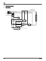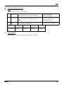
1
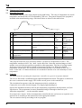
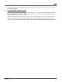
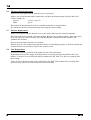
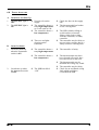
Installation, Operation &
Maintenance Instructions
Annealing Ovens
TLD models
This manual is for the guidance of operators of the above Carbolite products
and should be read before the oven is connected to the electricity supply.
CONTENTS
Section
1.0
2.0
3.0
4.0
5.0
6.0
7.0
8.0
9.0
page
Symbols & Warnings
Installation
Operating Instructions
Maintenance
Repairs & Replacements
Fault Analysis
Circuit Diagrams
Fuses & Power Settings
Specifications
1
3
4
6
7
9
10
11
12
Manuals are supplied separately for the temperature controller
(and overtemperature controller when fitted).
Please read the controller manuals before operating the oven.
1.0
MF18
TLD
SYMBOLS & WARNINGS
1.1
Switches and Lights
Supply Light: when the oven is connected to the electrical supply the light
in the adjacent switch glows
1.2
Warning Symbols
DANGER of electrical shock– read any warning printed by this symbol.
DANGER – hot surface. Read any warning printed by this symbol.
WARNING: all surfaces of an oven may be hot.
DANGER – read any warning printed by this symbol.
1.3
Introduction
Reproducible annealing of thermoluminescent dosimeters is essential to maintain constant
sensitivity and low background readings.
Use of the Carbolite TLD Annealing Oven ensures that the best results are consistently obtained.
The fan assisted air recirculating system eliminates the temperature gradients encountered in
simple gravity convection ovens. The risk of errors arising due to non-reproducible annealing is
greatly reduced by the automatic program controller.
The Carbolite annealing oven is supplied as a complete self contained unit. The front opening
side hinged door gives access to the work chamber which is fitted with two shelves. The air
recirculating fan draws air from the back of the chamber and passes it over the heating elements.
The reheated air is then returned to the chamber on all four sides. The temperature programmer is
conveniently located in the base of the equipment below the oven chamber.
2
MF18
TLD
2.0 INSTALLATION
2.1
Unpacking & Handling
Lift the unit by its base. Do not use the door or any other projecting cover or component to
support the equipment when moving it. Use two people to carry the oven where possible. Remove
any packing material from the inner chamber before use.
2.2
Siting & Setting Up
Place the oven on a level surface.
Ensure that there is free space around the oven. Ensure that any vents in the oven are not
obscured. During the operation of the oven hot air is exhausted from the vent on the top of the
oven while the cooling blower is in operation; there must be clearance of at least 500mm between
the top of the oven and any surface which must be made of non-combustible material.
Ensure that the oven is placed in such a way that it can be quickly switched off or disconnected
from the electrical supply - see below the top of the oven and the ceiling of the room. Always
ensure that the vent on the top of the oven is free to open.
2.3
Electrical Connections
Connection by a qualified electrician is recommended.
The oven is manufactured for use on a single phase supply, which may be Live to Neutral nonreversible, Live to Neutral reversible or Live to Live.
Check the Oven rating label before connection. The supply voltage should agree with the voltage
on the label, and the supply capacity should be sufficient for the amperage on the label.
The supply should be fused at the next size equal to or higher than the amperage on the label. A
table of the most common fuse ratings is also given in section 8.1 of this manual. Where a supply
cable is present there are internal supply fuses; customer fusing is preferred but not essential.
Oven with supply cable: either wire directly to an isolator or fit with a line plug.
Oven without supply cable: a permanent connection to a fused and isolated supply should be made
to the internal terminals after temporary removal of the oven back panel.
Connection by line plug: the plug should be within reach of the operator, and should be quickly
removable.
Connection to isolating switch: this should operate on both conductors and should be within reach
of the operator.
The supply MUST incorporate an earth (ground).
CONNECTION DETAILS
Supply
Terminal label
L
1-phase
N
PE
MF18
Cable colour
Brown
Blue
Green/Yellow
supply type
Live-Neutral
Reversible or Live-Live
To live
to either power conductor
To neutral
to the other power conductor
To earth (ground) to earth (ground)
3
TLD
3.0
OPERATING INSTRUCTIONS
3.1
Operating Program
The program consists of the stages shown in the graph below. The rates of temperature rise, dwell
temperature and dwell times are all adjustable by the user. The general format of the program is
installed at the manufacturing stage, with initial values as shown in the table below.
3
4
2
5
6
1
7
function
1 Start.
2 Heat at a controlled rate.
initial setting
program
heat up at 480°C/hour to 300°C
3
Dwell for a preset period.
dwell at 300°C for 1 hour
SEG.n 1
tGt
rAtE
SEG.n 2
4
Cool at a controlled rate.
Cool to 80°C assisted by inlet
blower
5
Dwell for a preset period.
80°C for 12 hours
6
Cool naturally to room
temperature.
Finish.
7
SEG.n 3
tGt
rAtE
SEG.n 4
SEG.n 5
SEG.n 6
rmP.r
300°C
8°C per min
dweLL
1 hour
rmP.r
80°C
20°C per min
dweLL
12 hours
SteP
0°C
End
This program causes the oven to heat up at 480°C per hour to a temperature of 300°C. The
temperature remains at 300°C for 1 hour. At the end of the 1 hour the setpoint changes to 80°C
and the oven cools down as quickly as possible to this temperature. The rate of cooling is quite
fast becaue of the air inlet blower which is incorporated in the oven. When the chamber
temperature reaches 80°C the second dwell period starts and the oven remains at 80°C for 12
hours. At the end of 12 hours the heaters are switched off and the oven cools naturally to room
temperature.
3.2
Controls
The instructions for operating the temperature controller are given in a separate manual.
The oven is fitted with a combined Supply light and Instrument switch. The light is on whenever
the oven is connected to the supply. The switch cuts off power to the controller(s).
The circulation fan operates when the instrument switch is switched on.
Connect the oven to the electrical supply. The Supply light should glow .
Operate the instrument switch to activate the temperature programmer; the O position is off, the
I position on. The programmer becomes illuminated and goes through a short test cycle.
Adjust the temperature – see the controller manual.
Overtemperature Option: If the overtemperature controller has not yet been set as required, set it
and activate it according to the instructions in the appropriate manual.
The oven starts to heat up according to the set program.
4
MF18
TLD
To switch the oven off, set the Instrument switch to O. If the oven is to be left off, isolate it from
the electrical supply.
3.3
Overtemperature Control (if fitted)
The overtemperature controller should typically be set at 15°C above the top temperature used by
the main programmer. If an overtemperature condition occurs, always investigate the possibility
that the main control system has failed.
An overtemperature condition always cuts off power to the heating elements. It is indicated by a
light in the overtemperature controller flashing. To reset the condition, either allow the oven to
cool, or increase the overtemperature setting, then follow the instructions in the manual supplied.
MF18
5
TLD
4.0 MAINTENANCE
4.1
General Maintenance
No routine maintenance is required other than the occasional replacement of consumable items.
The oven outer surface may be cleaned with a damp cloth. Do not allow water to enter the interior
of the case. Do not clean with organic solvents.
The fan motors are sealed for life; no lubrication is required.
4.2
Calibration
After prolonged use the controller and/or thermocouple could require recalibration. This would be
important for processes which require accurate temperature readings. A quick check using an
independent thermocouple and temperature indicator should be made from time to time to
determine whether full calibration is required.
For a quick check of the temperature shown by the control thermocouple and oven controller, a
portable temperature indicator and probe thermocouple may be used.
Depending on the controller, the controller manual may contain calibration instructions.
4.3
After Sales Service
Carbolite’s service division (Thermal Engineering Services) has a team of Service Engineers
capable of repair, calibration and preventive maintenance of furnace and oven products at our
customers’ premises throughout the world. We also sell spares by mail order. A telephone call or
fax often enables a fault to be diagnosed and the necessary spare part despatched.
Each furnace has its own record card at Carbolite. In all correspondence please quote the serial
number, model type and voltage given on the rating label of the furnace. The serial number and
model type are also given on the front of this booklet when supplied with a furnace.
To contact Thermal Engineering Services or Carbolite see the back page of this manual.
4.4
Recommended Spares Kits
Carbolite can supply individual spares, or a kit of the items most likely to be required. Ordering a
kit in advance can save time in the event of a breakdown. Please enquire for information on a
suitable kit for this model.
When ordering spares please quote the model details as requested above.
4.5
Power Adjustment
The control system incorporates electronic power limiting, but in these models the power limit is
set to 100% and the power limit parameter OP.Hi may be inaccessible to the operator.
Rarely, in the case of uncommon voltages (e.g. outside the range 220-240V or the 3-phase
equivalent), the power limit parameter may be set to a value other than 100%. Do not increase the
value to 100%. See section 8.2 for details of any power limit settings.
Occasionally the power limit is set to zero to permit demonstration of the controls without the
heating elements taking power. In this case the power limit is accessible to the operator and may
be reset to its standard value, usually 100: see section 8.2.
6
MF18
TLD
5.0 REPAIRS & REPLACEMENTS
5.1
Safety Warning – Disconnection from Supply
Always ensure that the oven is disconnected from the supply before repair work is
carried out.
5.2
Safety Warning - Refractory Fibrous Insulation
This oven contains refractory fibres in its thermal insulation. These materials may be
in the form of fibre blanket or felt, vacuum formed board or shapes, mineral wool
slab or loose fill fibre.
Normal use of the oven does not result in any significant level of airborne dust from these
materials, but much higher levels may be encountered during maintenance or repair.
Whilst there is no evidence of any long term health hazards, we strongly recommend that safety
precautions are taken whenever the materials are handled.
Exposure to dust from fibre which has been used at high temperatures may cause
respiratory disease.
When handling fibre always use an approved mask, eye protection, gloves and long
sleeved clothing.
Avoid breaking up waste material. Dispose of waste fibre in sealed containers.
After handling rinse exposed skin with water before washing gently with soap (not
detergent). Wash work clothing separately.
Before commencing any major repairs we recommend reference to the European Ceramic Fibre
Industry Association Bulletin No. 11 and the UK Health and Safety Executive Guidance Note
EH46.
We can provide further information on request. Alternatively our service division can quote for
any repairs to be carried out at your premises or ours.
5.3
Panel Removal
Disconnect the oven from the electrical supply.
To replace components (except controller), remove the front panel. Depending on the component,
it may be necessary to remove an internal panel. If in doubt, please consult Carbolite’s technical
department.
5.4
Temperature Controller Replacement
Ease apart the two lugs at the side; grip the instrument and withdraw it from its sleeve; push in the
replacement.
5.5
Solid-state Relay Replacement
Remove the front panel. Make a note how the wires are connected to the solid state relay, and
disconnect them.
Remove the solid state relay from the aluminium plate.
Replace and reconnect the solid state relay ensuring that the heat-conducting thermal pad is
sandwiched between the relay and the base panel or aluminium plate. Alternatively a thin layer of
white, heat-conducting silicon paste may be applied between the new relay and the plate.
The new solid state relay contains a built-in MOV which protects it from short periods of excess
voltage. If the old relay had a separate disc-shaped "MOV" connected between the high voltage
terminals of the old relay, discard the old MOV.
Replace the removed panel.
MF18
7
TLD
5.6
Thermocouple Replacement
Remove the front panel and the internal cover as necessary.
Make a note of the thermocouple connections, and how the thermocouple is placed and fixed.
Colour codings are:
negative
positive (type K)
white
green
Disconnect the thermocouple from its controller terminals or terminal block.
Re-assemble with the new thermocouple observing the colour coding.
5.7
Element Replacement
Remove front panel and the internal cover as necessary and locate the element terminals.
Disconnect the wires from the element terminals. Remove any starlock washers - these may need
to be cut with wire cutters. Remove any clips holding the element inside the chamber, and
withdraw the element.
Reverse the procedure with the new element.
Run the oven at a low temperature and check that it is controlling properly, to find out whether the
element failure was caused by a fault in the control circuit.
5.8
Fuse Replacement
Fuses are accessed by removal of the panel near the cable entry point.
Depending on the model, supply fuses and control circuit fuses may be mounted in their own
holders, or may be on a circuit board which contains an EMC filter. The fuses are marked with
their ratings.
Take care not to disconnect the wires leading from the EMC filter without first recording their
positions: they must be reconnected to the correct terminals.
8
MF18
TLD
6.0 FAULT ANALYSIS
A. Oven Does Not Heat Up
1.
2.
The SUPPLY light is
OFF
The SUPPLY light is
ON
Æ No power from the
supply
Æ The controller shows a
very high temperature
or a code such as S.br
Æ The controller shows a
low temperature
Æ There are no lights
glowing on the
controller
B.
Oven Overheats
1.
Oven only heats up
when the instrument
switch is ON
2.
Oven heats up when
the instrument switch
is OFF
MF18
Æ Check the fuses in the supply
line
Æ The thermocouple has broken
or has a wiring fault
Æ The SSR could be failing to
switch on due to internal
failure, faulty logic wiring
form the controller, or faulty
controller
Æ The controller may be faulty or
not receiving a supply due to a
faulty switch or a wiring fault
Æ The controller shows a
very high temperature
Æ The controller is faulty
Æ The controller shows a
low temperature
Æ The thermocouple may have
been shorted out or may have
been moved out of the oven
Æ The thermocouple may be
mounted the wrong way round
Æ The controller may be faulty
Æ Check for an accidental wiring
fault which could have
overloaded the SSR
Æ The SSR has failed
“ON”
9
TLD
7.0 CIRCUIT DIAGRAMS
7.1
Single Phase
N
L
only if
overtemperature
control fitted
F1 Filter
PE
Supply light
Instrument Switch
relay or
contactor
F2
e
l
e
m
e
n
t
(s)
circulation
fan
coil
overtemp.
controller
thermocouple
SSR
temperature
controller
thermocouple
alarm relay
cooling
fan
10
MF18
TLD
8.0 FUSES & POWER SETTINGS
8.1
Fuses
F1-F2: Refer to the circuit diagrams.
8.2
F1
Internal
supply fuses
Fitted if supply cable fitted.
Fitted on board to some types of EMC filter.
F2
Auxiliary
circuit fuses
Fitted on board to some types of EMC filter.
May be omitted up to 25Amp/phase supply
rating.
Customer
fuses
Required if no supply cable fitted.
Recommended if cable fitted.
on-board and up to 16 Amps:
32mm x 6mm type F
other: GEC Safeclip
2 Amps glass type F
On board: 20mm x 5mm
Other: 32mm x 6mm
See rating label for amperage; see
table below for fuse rating.
F1 - supply
fuses :
TLD/3
(220-240V)
5 Amps
TLD/28
(220-240V)
10 Amps
F2 - control
fuses:
TLD/3
2 Amps
TLD/28
5 Amps
Power Settings
All models are designed for a power limit (OP.Hi) of 100%.
MF18
11
Thank you for reading this data sheet.
For pricing or for further information, please contact us at our UK Office, using the details
below.
UK Office
Keison Products,
P.O. Box 2124, Chelmsford, Essex, CM1 3UP, England.
Tel: +44 (0)1245 600560
Fax: +44 (0)1245 808399
Email: [email protected]
Please note - Product designs and specifications are subject to change without notice. The user is responsible for determining the
suitability of this product.