1
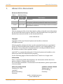
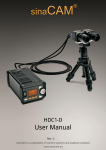
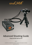
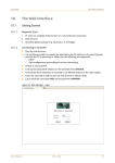
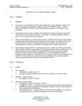
1. 2 (A) Content sinaCAM Content 1. About this Document .............................................................................................................. 3 2. Safety Instructions .................................................................................................................. 4 2.1 Warning Signs and Indications ..................................................................................... 4 2.2 General Safety................................................................................................................ 4 2.3 Specific Safety ................................................................................................................ 4 3. Regulatory Compliance .......................................................................................................... 5 4. Disposal ................................................................................................................................... 5 5. Introduction to sinaCAM ........................................................................................................ 5 6. Description .............................................................................................................................. 6 6.1 Remote Head HDC1-100................................................................................................ 6 6.2 Base Unit HDC1-200 ...................................................................................................... 7 6.2.1 The Control Panel .............................................................................................. 8 6.2.2 The Rear Panel ................................................................................................... 9 7. Installation ............................................................................................................................ 10 7.1 Minimum System Requirements ................................................................................ 10 7.2 Power Supply ............................................................................................................... 10 7.3 Remote Camera Head Connection ............................................................................. 10 7.4 Connecting the Hardware ........................................................................................... 10 7.5 Connection Examples .................................................................................................. 11 8. The Menus at a Glance ......................................................................................................... 12 9. Operation .............................................................................................................................. 13 9.1 Switching ON and OFF ................................................................................................. 13 9.2 Using the Menus .......................................................................................................... 13 10. Technical Specifications........................................................................................................ 14 FCC NOTE This equipment has been tested and found to comply with the limits for a Class B digital device, pursuant to part 15 of the FCC Rules. These limits are designed to provide reasonable protection against harmful interference in a residential installation. This equipment generates, uses and can radiate radio frequency energy and, if not installed and used in accordance with the instructions, may cause harmful interference to radio communications. However, there is no guarantee that interference will not occur in a particular installation. If this equipment does cause harmful interference to radio or television reception, which can be determined by turning the equipment off and on, the user is encouraged to try to correct the interference by one or more of the following measures: – Reorient or relocate the receiving antenna. – Increase the separation between the equipment and receiver. – Connect the equipment into an outlet on a circuit different from that to which the receiver is connected. – Consult the dealer or an experienced radio/TV technician for help. The user is cautioned that changes or modifications not expressly approved by the party responsible for compliance could void the user's authority to operate this equipment. 2 Rev.: 1.2 (A) Quick Start Guide sinaCAM 1. About this Document About this Document Document Revision History Table 1: Revision History Revision Date 1.0 April 18, 2012 First edition Description 1.1 May 29, 2012 Amendment of power terminal (figures), system battery description, technical specifications. Minor text corrections. 1.2 (A) July 12, 2012 Alignment of contents in several chapters with the sinaCAM user manual, revision A. Purpose This document provides a basic description, safety and quick start information for the sinaCAM camera system. However, this document does not replace the detailed user manual, which can be downloaded from: www.sinacam.eu Copyright Copyright © 2012, by Solectrix Systems and anadicon solutions. All rights reserved. All text, graphics, design and other works contained herein are copyrighted works of Solectrix Systems and anadicon solutions. Any redistribution or reproduction of any materials contained herein is strictly prohibited without the written consent of the copyright holders. ® sinaCAM is a registered trademark of Solectrix Systems and anadicon solutions and is their sole and exclusive property. On the following pages of this document the (®) mark is no longer used. Information Due to continuous product development, the information within this document is subject to change without notice. If you find any problems or inaccuracies in this document, please report them to us in writing. Solectrix Systems GmbH anadicon solutions GmbH Fuerther Str. 244b “Auf AEG” 90429 Nuremberg Germany Kammergasse 34 85354 Freising Germany mailto: [email protected] www.sinacam.eu Quick Start Guide Rev.: 1.2 (A) 3 Safety Instructions sinaCAM 2. Safety Instructions 2.1 Warning Signs and Indications CAUTION Indicates a hazardous situation which, if not avoided, could result in minor or moderate injury. NOTICE Indicates a potentially hazardous situation which, if not avoided, may result in property damage. 2.2 General Safety 2.3 4 Read and follow all safety and operating instructions before installing and operating the camera system. Specific Safety Only use the type of power source specified for this camera system. The use of a wrong power source could damage the camera system and/or cause fire or electric shock! Do not open the housing of the camera system. Risk of electric shock! Do not open the housing or attempt to repair or modify any part of the camera system. Repairs must only be carried out by authorized sinaCAM service centers. Do not store the camera system near a strong magnetic field, or in areas where it would be subjected to direct sunlight, extreme temperatures, high levels of humidity or severe vibrations. Do not use the camera system outside the specified operating temperature range. Keep all liquids away from the camera system. Do not place containers with liquids on top of the camera housing. Risk of fire, electric shock and/or damage! Do not use the camera system in places where it could come in contact with water, moisture, steam or dust. This could damage the camera system and/or cause fire or electric shock! Unplug the power cable by the plug, do not pull the cable. Unplug all cables before transporting the camera system or storing it inside a camera case. Rev.: 1.2 (A) Quick Start Guide sinaCAM 3. Regulatory Compliance Always put the protection cap onto the lens mount when transporting the remote camera heads without lenses. Do not allow laser beams to enter the camera lens or the lens mount opening, as this could cause damage to the CCD sensor. Regulatory Compliance The sinaCAM base station and the sinaCAM remote heads comply with the following regulations: 4. Low Voltage Directive (LVD), 2006/95/EC Electromagnetic compatibility (EMC): – 2004/108/EC – FCC 47 CFR Part 15 Subpart B Class B RoHS Disposal For European Union member states only: The use of this symbol indicates that this product must not be disposed of with household waste. By ensuring this product is disposed of correctly, you will help prevent negative consequences for the environment and human health. At the end of its lifespan, take the product to an appropriate recycling station. For more information about correct disposal of electrical and electronic equipment please contact your local authorities or your supplier where you purchased the product. 5. Introduction to sinaCAM sinaCAM is a small remote head HD studio camera system for professional 2D/3D broadcast and cinema production. Two signals of two sinaCAM remote heads are processed by the same image processor. This enables: – Pixel synchronous 3D output – Identical image properties, like white balance, brightness and contrast C-mount threads and the option to adjust the back focus by changing the flange back distance make it possible to use C-mount lenses for professional production. A choice of professional accessories, such as different battery adaptors, lens adaptors, lens accessories, handles, mounting plates and a carrying case increases application possibilities. Quick Start Guide Rev.: 1.2 (A) 5 Description sinaCAM 6. Description 6.1 Remote Head HDC1-100 Figure 1: The Remote Head A B Table 2: Item 6 C D E F G Elements and Controls of the Remote Head Designation Description A Locking lever Locking/unlocking the adjustment ring B Flange back adjustment ring Flange back distance adjustment ring rotates independently of C-mount and lens C Lens mount Standard C-mount thread D Lens mount lock Allows for lens scale position alignment in 30° steps E System LED Glows continuously when on, flashes while link detection is in progress and in case of malfunction F CoaXPress interface Remote head connection with base unit (via 75 ohms coaxial cable with BNC plug) G Bottom mount ¼” thread for attaching a tripod, handle, baseplate, holder, etc. Rev.: 1.2 (A) Quick Start Guide sinaCAM 6.2 Description Base Unit HDC1-200 Figure 2: The Base Unit B B D B C B A Table 3: Item Elements of the Base Unit Designation Description A Control panel Controls and graphical user interface display B Mounting points M4 thread for attaching a handle or to fix the base unit to a mounting plate C System battery compartment The system battery supplies power to the internal clock only. It does not supply the camera with power. Do not open the system battery compartment. Replacement of the system battery must only be carried out by authorized sinaCAM service centers. D Rear panel Panel with all terminals to connect equipment Quick Start Guide Rev.: 1.2 (A) 7 Description 6.2.1 sinaCAM The Control Panel Figure 3: The Control Panel A B C F1 POWER D Table 4: Item 8 F2 E F G H Controls and their Functions Designation Description A USB 2.0 port Enables frame grabs to USB sticks B Display Graphical user interface display C F1 button To select a menu item as displayed D Power switch Turns power ON or OFF E Power LED Glows red when the unit is connected to the power supply, and glows green when the unit is powered on F Arrow buttons To select a menu item as displayed G F2 button To select a menu item as displayed H Scroll wheel Scroll wheel and pushing button to navigate through the menus and select options Rev.: 1.2 (A) Quick Start Guide sinaCAM 6.2.2 Description The Rear Panel Figure 4: Arrangement of the Terminals A B D C E F Table 5: Terminals on the Rear Panel Item Designation G H Description A Remote head terminals (1, 2) CoaXPress interface with 18 V power supply for the remote camera heads, connection via 75 ohms coaxial cable with BNC plug B SYNC (OUT, IN) Terminals for, e.g. an additional camera an external sync generator C HD-SDI output (1A, 1B) Terminals for, e.g., a HD-SDI monitor, a recording device or a 2D/3D converter; 1A/1B provides the image signal coming from remote head terminal 1 D HD-SDI output (2A, 2B) For the same equipment as listed next to item C; 2A/2B provides the image signal coming from remote head terminal 2 E LAN 100 MBit Ethernet service communication port F DVI output Connection of a digital HD monitor G AUX 10-pin terminal, auxiliary signals for remote control unit, timecode or exposure trigger H Power input 12 – 24 V Connection of a power supply adapter, 12 – 24 V DC, minimum 30 W Quick Start Guide Rev.: 1.2 (A) 9 Installation sinaCAM 7. Installation 7.1 Minimum System Requirements Shooting with sinaCAM requires the below listed minimum equipment: 7.2 A sinaCAM camera system, consisting of – sinaCAM base unit – one or two sinaCAM remote heads (depending on shooting in 2D or 3D) Further equipment, like – C-mount lens suitable for 2/3” CCD cameras – Remote head cable, 75 ohms coaxial cable with BNC plugs – Video output cable for DVI and/or HD-SDI – Digital HD monitor, able to display the desired output format and frame rate – Digital recording device – DC power supply for the sinaCAM base unit Power Supply It is recommended to only use official sinaCAM accessories as a power supply. For official sinaCAM accessories please refer to www.sinacam.eu CAUTION The use of a wrong power supply can cause fire or electric shock. NOTICE The use of a wrong power supply may cause damage to the camera system. 7.3 Remote Camera Head Connection The base unit supplies 18 V power to the remote camera head terminals 1 and 2. NOTICE Connect only sinaCAM remote camera heads to terminals 1 and 2 of the base unit. Connection of any other equipment to terminal 1 or 2 may not only cause damage to the camera system, but also to the connected equipment. 7.4 Connecting the Hardware Make sure that all hardware to be installed is switched off. Connect all hardware to the base unit. Switch on all hardware and the base unit. 10 Rev.: 1.2 (A) Quick Start Guide sinaCAM 7.5 Installation Connection Examples Figure 5: Standard Single-Link Setup 3D Monitor REC DC IN 12...24V REC EVF 3D Recorder Figure 6: (Electronic View Finder) Advanced Dual-Link Setup HD Monitor DL C RE Figure 7: Dual Link Recorder DC IN 12...24V DL C RE Dual Link Recorder Broadcast Setup Genlock OUT Genlock IN DC IN 12...24V LIVE Broadcast Quick Start Guide Remote Control Unit Rev.: 1.2 (A) 11 The Menus at a Glance The Menus at a Glance F2 - Save F1 - SA FPS 50i Shutter FULL Gain ASA 200 WBalance 5600K Gamma&CM R709LEG LEVEL MODE SYS 24p; 24psf; 25p; 25psf; 50i; 30p; 30psf; 60i; 48pDL; 50pDL; 60pDL; 23,9p; 23,9psf; 29,9p; 29,9psf; 59,9i; 59,9pDL; 720 24p; 720 25p; ... 720 30p; 720 50p; 720 60p; 720 23p; 720 29p; 720 59p ... FULL; 1/50; 1/60; 1/125; 1/250; 1/500; 1/1000; 1/2000; 1/5000 ... ASA 200; ASA 400; ASA 800 ... 3200K; 4300K; 5600K; 6500K; USER ... R709LEG; R709EXT ; SlogLEG; SlogEXT FPS Shutter Gain WBalance Gamma&CM BACK MAN WB ADJUST 0 0 0 0 0 0 MODE_MENU DVI-Mode CAM1 H-Flip None GenLock FreeRun Sharpen 0 Red level Head12 Blue level Head12 ... -99 to +99 LEVEL ADJUST WhiteLevel Head12 BlackLevel Head12 BBalanceRed BBalanceBlue BACK 50i FULL ASA 200 USER R709LEG AWB! 0 0 0 0 BACK ... -99 to +99 8. sinaCAM HOME ... CAM1; CAM2; AltFrame; AltLine; Subtract; Anaglyph ... None; CAM1; CAM2; Both ... FreeRun; Slv+Term; SlvChain; ExpTrgIn ... 0 to 99 BACK SYSTEM MENU Factory Preset ###.###.##.## DD.MM.YYYY HH:MM BACK INFO Memory: Version B-SW: B-FW: Head 1: Head 2: BACK INFO ##### kB ######## ######## ######## ######## HOME Due to continuous product development, the content of the menus is subject to change without notice. 12 Rev.: 1.2 (A) Quick Start Guide sinaCAM Operation 9. Operation 9.1 Switching ON and OFF After the base unit is connected to the power supply, the power LED glows red. Switching ON Push the power switch. – The power LED of the base unit changes from red to green. – The HOME menu screen comes on. – The system LED of the remote head lights up in orange, starts flashing green and finally glows green continuously. Note: The system LED of the remote head can indicate additional status information. For more indications refer to sinaCAM’s detailed user manual. Switching OFF Push and hold the power switch for about 4 seconds. – The power LED of the base unit changes from green to red. – The display goes off. – The system LED of the remote head goes off. 9.2 Using the Menus Use the arrow buttons and F1/F2 buttons to select menu items as displayed. F1 F2 Use the scroll wheel to select and to confirm settings. Figure 8: Scroll Wheel Turn the scroll wheel to select. Push the scroll wheel to confirm. Quick Start Guide Rev.: 1.2 (A) 13 Technical Specifications 10. sinaCAM Technical Specifications Remote Head HDC1-100 Image Sensor 2/3” Single Chip Kodak CCD Sensor (RGB) 2004x1144 Pixels, Progressive Scan Sensitivity 2000 Lux @ f 8.0 / 0 dB Gain (100% video out) 160 Lux @ f 2.2 / 0 dB Gain (100% video out) Resolution 1920x1080 Pixels Dynamic Range 13.5 f-stops Signal/Noise Ratio 64 dB @ 0 dB Gain Interface CoaXPress, 75 ohms BNC Cable Max. Cable Lengths 80 m (260 ft) with Standard BNC Cable 180 m (590 ft) with Gepco VHD1100 Cable (Option) Lens Mount C-mount with Flange Back Distance adjustment Power Consumption 4.6 W max. Operating Temperature Range 0 to 45 °C (32 to 113 °F) Base Unit HDC1-200 14 Digital Signal Processing Single Chip DSP (dual 14-Bit) White Balance Modes AWB: Automatic White Balance (Push to set White Balance) 3200 K, 4300 K, 5600 K, 6500 K MAN: Manual White Balance (red and blue adjust) Black Level adjustable Exposure Control 200, 400, 800 ASA Gamma REC 709, S-Log, custom via web interface Electronic Shutter Full Frame, 1/50 s to 1/5000 s Remote Head Connections CoaXPress (via 75 ohms BNC Cable) Output Signals up to 4x HD-SDI (SMPTE 292M, 372M) DVI (Digital Monitor Output 1920x1080 @ 60Hz) Rev.: 1.2 (A) Quick Start Guide sinaCAM Technical Specifications Base Unit HDC1-200 HD-SDI Video Formats YCbCr 4:2:2 / 10 Bit 1920x1080 / 24p, 24psf, 25p, 25psf, 50i, 30p, 30psf, 60i, 48pDL*, 50pDL*, 60pDL*, 23.98p, 23.98psf, 29.97p, 29.97psf, 59.94i, 59.94pDL* * = HD-SDI Dual-Link Mode With May 2012 firmware update: 1280x720 / 24p, 25p, 30p, 50p, 60p, 23.98p, 29.97p, 59.94p 3D Monitoring CAM1, CAM2, Alternate Frame, Alternate Line, Subtract, Anaglyph Synchronization Internal or GenLock to Tri-Level Sync or Black Burst Communication Ports 100 MBit Ethernet, USB 2.0, RS232 / 485 User Interface Graphical User Interface, Web Interface 10-Pin AUX Terminal RS232 / 485, Exposure Trigger I/O, Timecode I/O 2-Pin Power Terminal 12 to 24 V DC Power Consumption 30 W max. (incl. two Remote Camera Heads) Operating Temperature Range 0 to 45 °C (32 to 113 °F) Quick Start Guide Rev.: 1.2 (A) 15