1
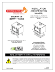
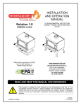
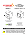
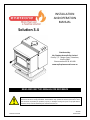
INSTALLATION AND OPERATION MANUAL Solution 3.4 Distributed by: My Fireplace Australia Pty Limited Factory 2, 5‐7 Hogan Court, Pakenham, Victoria 3810 Phone number 03 59 415 008 www.myfireplaceaustralia.com.au READ AND KEEP THIS MANUAL FOR REFERENCE Printed in Canada This manual is available for free download on the distributor’s web site. It is a copyrighted document. Re‐sale is strictly prohibited. The distributor may update this manual from time to time and cannot be responsible for problems, injuries, or damages arising out of the use of information contained in any manual obtained from unauthorized sources. 45732A 04‐05‐2015 THANK YOU FOR CHOOSING THIS WOOD FIRE We want to congratulate you on your purchase and wish to help you get maximum satisfaction from your wood fire. In the pages that follow, we will give you advice on wood heating and controlled combustion as well as technical specifications regarding installation, operation and maintenance of the model you have chosen. The instructions pertaining to the installation of your wood fire comply with AS/NZS 4012/4013 (1999) and AS/NZS 2918:2001 standards. Please read this entire manual before you install and use your new wood fire. Failure to follow instructions may result in property damage, bodily injury, or even death. It is important that you follow the installations guidelines exactly. Consult your local city, borough or shire council about restrictions and installations requirements in your area and the need to obtain a permit. KEEP THIS INSTRUCTION MANUAL FOR FUTURE REFERENCE. 2 Solution 3.4 Installation and Operation Manual Table of content PART A ‐ OPERATION AND MAINTENANCE ............................................. 6 1 1.1 2 Safety Information ........................................................................... 6 Summary of Operation and Maintenance Cautions and Warnings ...................................... 6 General Information ........................................................................ 7 2.1 ENERZONE Solution 3.4 Specifications .................................................................................. 7 2.2 Zone Heating and How to Make it Work for You ................................................................ 10 2.3 The Benefits of Low Emissions and High Efficiency ............................................................. 10 2.4 Enerzone’s Commitment to You and the Environment ...................................................... 11 2.4.1 What is Your New Wood fire Made Of? .......................................................................... 11 3 Fuel ............................................................................................... 12 3.1 Materials That Should Not be Burned ................................................................................. 12 3.2 How to Prepare or Buy Good Firewood .............................................................................. 12 3.2.1 What is Good Firewood? ................................................................................................. 12 3.2.2 Tree Species ..................................................................................................................... 12 3.2.3 Log Length ........................................................................................................................ 12 3.2.4 Piece Size .......................................................................................................................... 13 3.2.5 How to Dry Firewood ....................................................................................................... 14 3.2.6 Judging Firewood Moisture Content ............................................................................... 15 3.3 Manufactured Logs .............................................................................................................. 15 4 Operating Your Wood fire .............................................................. 16 4.1 Your First Fires ..................................................................................................................... 16 4.2 Lighting Fires ........................................................................................................................ 16 4.2.1 Conventional Fire Starting ............................................................................................... 17 4.2.2 The Top Down Fire ........................................................................................................... 17 4.2.3 Two Parallel Logs .............................................................................................................. 17 4.2.4 Using Fire Starters ............................................................................................................ 18 4.3 Maintaining Wood Fires ...................................................................................................... 18 4.3.1 General Advice ................................................................................................................. 18 4.3.2 Ash Removal ..................................................................................................................... 18 4.3.3 Raking Charcoal ................................................................................................................ 19 4.3.4 Firing Each New Load Hot ................................................................................................ 20 4.3.5 Turning Down the Air Supply ........................................................................................... 20 4.3.6 Building Different Fires for Different Needs .................................................................... 21 Solution 3.4 Installation and Operation Manual 3 5 Maintaining Your Wood Heating System ....................................... 23 5.1 Wood fire Maintenance ...................................................................................................... 23 5.1.1 Plated Finish Maintenance .............................................................................................. 23 5.1.2 Cleaning Door Glass ......................................................................................................... 23 5.1.3 Door Adjustment .............................................................................................................. 24 5.1.4 Replacing the Door Gasket .............................................................................................. 25 5.1.5 Replacing the Glass Gasket and/or the Glass .................................................................. 25 5.1.6 Cleaning and Painting the Wood fire ............................................................................... 26 5.2 Flue and Flue System Maintenance ..................................................................................... 26 5.2.1 Why Flue System Cleaning is Necessary .......................................................................... 26 5.2.2 How Often Should You Clean the Flue System? .............................................................. 27 5.2.3 Cleaning the Flue System ................................................................................................. 27 PART B – INSTALLATION ....................................................................... 28 6 6.1 6.2 7 7.1 7.2 7.3 7.4 8 Safety Information ......................................................................... 28 Summary of Installation Cautions and Warnings ................................................................ 28 Regulations Covering Wood fire Installation ....................................................................... 29 Clearances to Heat‐Sensitive Materials .......................................... 30 Location of the Certification Label ...................................................................................... 30 Clearances to Walls and Ceiling ........................................................................................... 30 Floor Protector..................................................................................................................... 31 Reducing Wall and Ceiling Clearances Safely ...................................................................... 32 The Flue System ............................................................................. 34 8.1 General ................................................................................................................................ 34 8.2 Suitable Flue Systems .......................................................................................................... 34 8.2.1 Factory built Insulated Flue Kits ....................................................................................... 34 8.2.2 Masonry Flue Systems ..................................................................................................... 35 8.3 Minimum Flue System Height ............................................................................................. 35 8.4 The Relationship Between the Flue System and the House................................................ 36 8.4.1 Why Inside Flue Systems are Preferred ........................................................................... 36 8.4.2 Why the Flue System Should Penetrate the Highest Heated Space................................ 37 8.5 Installing the flue Connector ............................................................................................... 37 4 Solution 3.4 Installation and Operation Manual Appendix 1: Installing the Door Overlay ............................................... 40 Appendix 2: Installing the DECORATIVE PANELs ................................... 41 Appendix 3: Installation and Use of the air circulation fan and Thermodisc ...................................................................... 42 Appendix 4: Installation of Secondary Air Tubes and Baffle .................. 44 Appendix 5: Exploded Diagram and Parts List ....................................... 48 ENERZONE PRODUCT WARRANTY ........................................................ 51 REGISTER YOU WARRANTY ONLINE To receive full warranty coverage, you will need to show evidence of the date you purchased your wood fire. Keep your sales invoice. We also recommend that you register your warranty online at www.myfireplaceaustralia.com.au Registering your warranty online will help us track rapidly the information we need on your wood fire. Solution 3.4 Installation and Operation Manual 5 PART A ‐ OPERATION AND MAINTENANCE Please see Part B for installation instructions. 1 SAFETY INFORMATION 1.1 SUMMARY OF OPERATION AND MAINTENANCE CAUTIONS AND WARNINGS • HOT WHILE IN OPERATION, KEEP CHILDREN, CLOTHING AND FURNITURE AWAY. CONTACT MAY CAUSE SKIN BURNS. GLOVES MAY BE NEEDED FOR WOOD FIRE OPERATION. • USING A WOOD FIRE WITH CRACKED OR BROKEN COMPONENTS, SUCH AS GLASS OR FIREBRICKS OR BAFFLES MAY PRODUCE AN UNSAFE CONDITION AND MAY DAMAGE THE WOOD FIRE. • OPEN THE AIR CONTROL FULLY BEFORE OPENING FIRING DOOR. • OPERATE ONLY WITH DOOR FULLY CLOSED. IF DOOR IS LEFT PARTLY OPEN, GAS AND FLAME MAY BE DRAWN OUT OF THE OPENING, CREATING RISKS FROM BOTH FIRE AND SMOKE. • THIS WOOD FIRE IS NOT DESIGNED TO BE USED WITH THE DOOR OPEN. THE DOOR MAY BE OPEN ONLY DURING LIGHTING PROCEDURES OR RELOADING. DO NOT LEAVE THE WOOD FIRE UNATTENDED WHEN THE DOOR IS SLIGHTLY OPENED DURING IGNITION. ALWAYS CLOSE THE DOOR AFTER IGNITION. • NEVER USE GASOLINE, GASOLINE‐TYPE LANTERN FUEL (NAPHTHA), FUEL OIL, MOTOR OIL, KEROSENE, CHARCOAL LIGHTER FLUID, OR SIMILAR LIQUIDS OR AEROSOLS TO START OR ‘FRESHEN UP’ A FIRE IN THIS WOOD FIRE. KEEP ALL SUCH LIQUIDS OR AEROSOLS WELL AWAY FROM THE WOOD FIRE WHILE IT IS IN USE. • DO NOT CONNECT TO ANY AIR DISTRIBUTION DUCT OR SYSTEM. • DO NOT STORE FUEL WITHIN HEATER MINIMUM INSTALLATION CLEARANCES. • BURN ONLY SEASONED NATURAL FIREWOOD. • THE USE OF SOME TYPES OF PRESERVATIVE‐TREATED WOOD AS A FUEL CAN BE HAZARDOUS. • DO NOT BURN: o GARBAGE OF ANY KIND, o COAL OR CHARCOAL, o TREATED, PAINTED OR COATED WOOD, o PLYWOOD OR PARTICLE BOARD, o FINE PAPER, COLORED PAPER OR CARDBOARD, o SALT WATER DRIFTWOOD, OR o RAILROAD TIES. DO NOT ELEVATE THE FIRE BY USING A GRATE IN THIS WOOD FIRE. • • 6 THIS APPLIANCE SHOULD BE MAINTAINED AND OPERATED AT ALL TIMES IN ACCORDANCE WITH THESE INSTRUCTIONS. Solution 3.4 Installation and Operation Manual 2 GENERAL INFORMATION 2.1 ENERZONE SOLUTION 3.4 SPECIFICATIONS Combustible: Wood Heating capacity* 250 m2 Maximum average heat output – hardwood (Australia): 12.8 kW Average efficiency – hardwood (Australia): 67 % Average emissions – hardwood (Australia): 1.1 g/kg Approximate Burn Time* 9 to 10 hours Color : Metallic black Flue Spigot Diameter : 150 mm Flue system : Triple skin flue kit Minimum Flue Height (from floor protector): 4.6 meters Maximum Log Length : 556 mm sideways** Log loading : Sideways Firebox Volume : 0,104 m3 Weight: 248 kg Baffle Material C‐cast * Burn time and heating capacity may vary subject to location in home, flue system draft, flue system diameter, locality, heat loss factors, climate, fuels and other variables. ** Sideways: through the door you see the sides of the logs. Solution 3.4 Installation and Operation Manual 7 8 Solution 3.4 Installation and Operation Manual Solution 3.4 Installation and Operation Manual 9 2.2 ZONE HEATING AND HOW TO MAKE IT WORK FOR YOU Your new Enerzone Solution 3.4 wood fire is a space heater, which means it is intended to heat the area it is installed in, as well as spaces that connect to that area, although to a lower temperature. This is called zone heating and it is an increasingly popular way to heat homes or spaces within homes. Zone heating can be used to supplement another heating system by heating a particular space within a home, such as a basement family room or an addition that lacks another heat source. Houses of moderate size and relatively new construction can be heated with a properly sized and located wood fire. Whole house zone heating works best when the wood fire is located in the part of the house where the family spends most of its time. This is normally the main living area where the kitchen, dining and living rooms are located. By locating the wood fire in this area, you will get the maximum benefit of the heat it produces and will achieve the highest possible heating efficiency and comfort. The space where you spend most of your time will be warmest, while bedrooms and basement (if there is one) will stay cooler. In this way, you will burn less wood than with other forms of heating. Although the wood fire may be able to heat the main living areas of your house to an adequate temperature, we strongly recommend that you also have a conventional oil, gas or electric heating system to provide backup heating. Your success with zone heating will depend on several factors, including the correct sizing and location of the wood fire, the size, layout and age of your home and your climate zone. Three‐ season vacation homes can usually be heated with smaller wood fires than houses that are heated all winter. 2.3 THE BENEFITS OF LOW EMISSIONS AND HIGH EFFICIENCY The low smoke emissions produced by the special features inside the Enerzone Solution 3.4 firebox mean that your household will release up to 90 percent less smoke into the outside environment than if you used an older conventional wood fire. But there is more to the emission control technologies than protecting the environment. The smoke released from wood when it is heated contains about half of the energy content of the fuel. By burning the wood completely, your wood fire releases all the heat energy from the wood instead of wasting it as smoke up the flue system. Also, the features inside the firebox allow you to reduce the air supply to control heat output, while maintaining clean and efficient flaming combustion, which boosts the efficient delivery of heat to your home. The emission control and advanced combustion features of your wood fire can only work properly if your fuel is in the correct moisture content range of 15 to 20 percent. See Section 3 of this manual for suggestions on preparing fuelwood and judging its moisture. 10 Solution 3.4 Installation and Operation Manual 2.4 ENERZONE’S COMMITMENT TO YOU AND THE ENVIRONMENT The Enerzone team is committed to protecting the environment, so we do everything we can to use only materials in our products that will have no lasting negative impact on the environment. 2.4.1 WHAT IS YOUR NEW WOOD FIRE MADE OF? The body of your wood fire, which is most of its weight, is carbon steel. Should it ever become necessary many years in the future, almost the entire wood fire can be recycled into new products, thus eliminating the need to mine new materials. The paint coating on your wood fire is very thin. Its VOC content (Volatile Organic Components) is very low. VOCs can be responsible for smog, so all the paint used during the manufacturing process meets the latest air quality requirements with regards to VOC reduction or elimination. The air tubes are stainless steel, which can also be recycled. The C‐Cast baffle is made of an aluminosilicate fibre material that is compressed with a binder to form a rigid board. C‐Cast can withstand temperatures above 1093 °c. It is not considered hazardous waste. Disposal at a landfill is recommended. Firebrick is mainly composed of silicon dioxide, also known as silica, an earth derived product. It is most commonly found in nature in the form of sand and clay. Disposal at a landfill is recommended. The door and glass gaskets are fibreglass which is spun from melted sand. Black gaskets have been dipped into a solvent‐free solution. Disposal at a landfill is recommended. The door glass is a 5 mm thick ceramic material that contains no toxic chemicals. It is basically made of raw earth materials such as sand and quartz that are combined in such a way to form a glass at high temperatures. Ceramic glass will not re‐melt in the same way as normal glass, so it should not be recycled with your regular household products. Disposal at a landfill is recommended. Solution 3.4 Installation and Operation Manual 11 3 FUEL 3.1 MATERIALS THAT SHOULD NOT BE BURNED • GARBAGE OF ANY KIND, • COAL OR CHARCOAL, • TREATED, PAINTED OR COATED WOOD, • PLYWOOD OR PARTICLE BOARD, • FINE PAPER, COLORED PAPER OR CARDBOARD, • SALT WATER DRIFTWOOD • MANUFACTURED LOGS CONTAINING WAX OR CHEMICAL ADDITIVES • RAILROAD TIES • LIQUIDS SUCH AS KEROSCENE OR DIESEL FUEL TO START A FIRE 3.2 HOW TO PREPARE OR BUY GOOD FIREWOOD 3.2.1 WHAT IS GOOD FIREWOOD? Good firewood has been cut to the correct length for the wood fire, split to a range of sizes and stacked in the open until its moisture content is reduced to 15 to 20 per cent. 3.2.2 TREE SPECIES The tree species the firewood is produced from is less important than its moisture content. The main difference in firewood from various tree species is the density of the wood. Hardwoods such as gums, Manuka or ironbark are denser than softwoods. Hard wood will produce long‐lasting coal beds combined to more heat and longer burn cycles. Old, leaky cast iron wood fires wouldn’t hold a fire overnight unless they were fed large pieces of hardwood. That is no longer true. You can successfully heat your home by using less wood and give the forest a break at the same time. 3.2.3 LOG LENGTH Logs should be cut about 25 mm (1”) shorter than the firebox so they fit in easily. Pieces that are slightly too long make loading the wood fire very difficult. The most common standard length of firewood is 400 mm (16”). 12 Solution 3.4 Installation and Operation Manual The pieces should be a consistent length, with a maximum of 25 mm (1”) variation from piece to piece. 3.2.4 PIECE SIZE Firewood dries more quickly when it is split. Large unsplit rounds can take years to dry enough to burn. Even when dried, unsplit logs are difficult to ignite because they don’t have the sharp edges where the flames first catch. Logs as small as 75 mm (3”) should be split to encourage drying. Wood should be split to a range of sizes, from about 75 mm to 150 mm (3” to 6”) in cross section. Having a range of sizes makes starting and rekindling fires much easier. Often, the firewood purchased from commercial suppliers is not split finely enough for convenient stoking. It is sometimes advisable to resplit the wood before stacking to dry. Solution 3.4 Installation and Operation Manual 13 3.2.5 HOW TO DRY FIREWOOD Firewood that is not dry enough to burn is the cause of most complaints about wood fires. The complaints usually involve a lack of heat and dirty door glass. Here are some things to consider in estimating drying time: • • • • • • • • • • 14 firewood takes a long time to dry firewood bought from a dealer is rarely dry enough to burn, so it is advisable to buy the wood in spring and dry it yourself drying happens faster in dry weather than in damp, maritime climates drying happens faster in warm summer weather than in winter weather small pieces dry more quickly than large pieces split pieces dry more quickly than unsplit rounds softwoods take less time to dry than hardwoods hardwoods like gums, Manuka and ironbark can take one, or even two years to dry fully, especially if the pieces are big firewood dries more quickly when stacked in the open where it is exposed to sun and wind; it takes much longer to dry when stacked in a wood shed firewood that is ready to burn has a moisture content between15 and 20% by weight and will allow your wood fire to produce its highest possible efficiency Solution 3.4 Installation and Operation Manual 3.2.6 JUDGING FIREWOOD MOISTURE CONTENT You can find out if some firewood is dry enough to burn by using these guidelines: • • • • • • cracks form at the ends of logs as they dry as it dries in the sun, the wood turns from white or cream coloured to grey or yellow, bang two pieces of wood together; seasoned wood sounds hollow and wet wood sounds dull, dry wood is much lighter in weight than wet wood, split a piece, and if the fresh face feels warm and dry it is dry enough to burn; if it feels damp, it is too wet, burn a piece; wet wood hisses and sizzles in the fire and dry wood does not. You could buy a wood moisture meter to test your firewood. 3.3 MANUFACTURED LOGS Do not burn manufactured logs made of wax impregnated sawdust or logs with any chemical additives. Manufactured logs made of 100% compressed sawdust can be burned, but use caution in the number of these logs burned at one time. Start with one manufactured log and see how the wood fire reacts. You can increase the number of logs burned at a time to making sure the temperature never rises higher than 246 °C (475 °F) on a magnetic thermometer for installation on wood fire flue. The thermometer should be placed about 450 mm (18”) above the wood fire. Higher temperatures can lead to overheat and damage your wood fire. Solution 3.4 Installation and Operation Manual 15 4 OPERATING YOUR WOOD FIRE • NEVER OVERFIRE YOUR WOOD FIRE. IF ANY PART OF THE WOOD FIRE STARTS TO GLOW RED, OVER FIRING IS HAPPENING. READJUST THE AIR INTAKE CONTROL AT A LOWER SETTING. • NEVER LOAD YOUR WOOD FIRE UP TO THE BAFFLE. ALWAYS LEAVE 5 TO 10 CENTIMETERS TO ALLOW PROPER COMBUSTION THROUGH SECONDARY AIR OPENINGS (NEVER PUT WOOD ABOVE THE FIREBRICK LINING ON THE FIREBOX). THIS WILL ALSO PREVENT OVERFIRING OF YOUR WOOD FIRE. • SHOULD THERE BE A SOOT OR CREOSOTE FIRE IN YOUR FLUE SYSTEM, CLOSE THE AIR CONTROL COMPLETELY. IMMEDIATELY CALL THE FIRE DEPARTMENT. 4.1 YOUR FIRST FIRES Two things will happen as you burn your first few fires; the paint cures and the internal components of the wood fire are conditioned. As the paint cures, some of the chemicals vaporize. The vapors are not poisonous, but they do smell bad. Fresh paint fumes can also cause false alarms in smoke detectors. So, when you first light your wood fire, be prepared by opening doors and/or windows to ventilate the house. As you burn hotter and hotter fires, more of the painted surfaces reach the curing temperature of the paint. The smell of curing paint does not disappear until you have burned one or two very hot fires. Burn one or two small fires to begin the curing and conditioning process. Then build bigger and hotter fires until there is no longer any paint smell from the wood fire. Once the paint smell disappears, your wood fire is ready for serious heating. 4.2 LIGHTING FIRES Each person who heats with wood develops their own favorite way to light fires. Whatever method you choose, your goal should be to get a hot fire burning quickly. A fire that starts fast produces less smoke and deposits less creosote in the flue system. Here are three popular and effective ways to start wood fires. 16 Solution 3.4 Installation and Operation Manual 4.2.1 CONVENTIONAL FIRE STARTING The conventional way to build a wood fire is to bunch up 5 to 10 sheets of plain newspaper and place them in the firebox. Next, place 10 or so pieces of fine kindling on the newspaper. This kindling should be very thin; less than 25 mm (1”). Next, place some larger kindling pieces on the fine kindling. Open the air control fully and light the newspaper. If you have a tall, straight flue system you should be able to close the door immediately and the fire will ignite. If your flue has elbows or an outside flue system, you may need to leave the door closed but unlatched for a few minutes as the newspaper ignites and heat in the flue system produces some draft. Once the fire has ignited, close the door and leave the air control fully open. A conventional kindling fire with paper under finely split wood. DO NOT LEAVE THE WOOD FIRE UNATTENDED WHEN THE DOOR IS SLIGHTLY OPENED DURING IGNITION. ALWAYS CLOSE THE DOOR AFTER IGNITION. After the kindling fire has mostly burned, you can add standard firewood pieces until you have a fire of the right size for the conditions. 4.2.2 THE TOP DOWN FIRE The top down fire starting method solves two problems with the conventional method: first, it does not collapse and smother itself as it burns; and second, it is not necessary to build up the fire gradually because the firebox is loaded before the fire is lit. A top down fire can provide up to two hours of heating or more. The top down method only works properly if the wood is well‐seasoned. Start by placing three or four full‐sized split pieces of dry firewood in the firebox. Next, place 4 or 5 more finely split pieces of firewood (50 mm to 75 mm [2” to 3”] in dia.) on the base logs at right angles (log cabin style). Now place about 10 pieces of finely split kindling on the second layer at right angles. The fire is topped with about 5 sheets of newspaper. You can just bunch them up and stuff them in between the kindling and the underside of the baffle. Or you can make newspaper knots by rolling up single sheets corner to corner and tying a knot in them. The advantage of knots is that they don’t roll off the fire as they burn. Light the newspaper and watch as the fire burns from top to bottom. 4.2.3 TWO PARALLEL LOGS Place two spit logs in the firebox. Place a few sheets of twisted newspaper between the logs. Now place some fine kindling across the two logs and some larger kindling across those, log cabin style. Light the newspaper. Solution 3.4 Installation and Operation Manual 17 4.2.4 USING FIRE STARTERS Many people like to use commercial fire starters instead of newspaper. Some of these starters are made of sawdust and wax and others are specialized flammable solid chemicals. Follow the package directions for use. Gel starter may be used but only if there are no hot embers present. Use only in a cold firebox to start a fire. DO NOT USE FLAMMABLE LIQUIDS SUCH AS GASOLINE, NAPHTHA, FUEL OIL, MOTOR OIL, OR AEROSOLS TO START OR REKINDLE THE FIRE. 4.3 MAINTAINING WOOD FIRES 4.3.1 GENERAL ADVICE Wood heating with a space heater is very different than other forms of heating. There will be variations in the temperature in different parts of the house and there will be variations in temperature throughout the day and night. This is normal, and for experienced wood burners these are advantages of zone heating with wood. Do not expect steady heat output from your wood fire. It is normal for its surface temperature to rise after a new load of wood is ignited and for its temperature to gradually decline as the fire progresses. This rising and falling of temperature can be matched to your household routines. For example, the area temperature can be cooler when you are active, such as when doing housework or cooking, and it can be warmer when you are inactive, such as when reading or watching television. Wood burns best in cycles. A cycle starts when a new load of wood is ignited by hot coals and ends when that load has been consumed down to a bed of charcoal about the same size as it was when the wood was loaded. Do not attempt to produce a steady heat output by placing a single log on the fire at regular intervals. Always place at least three, and preferably more, pieces on the fire at a time so that the heat radiated from one piece helps to ignite the pieces next to it. Each load of wood should provide several hours of heating. The size of each load can be matched to the amount of heat needed. When you burn in cycles, you rarely need to open the wood fire’s loading door while the wood is flaming. This is an advantage because there is more chance that smoke will leak from the wood fire when the door is opened as a full fire is burning. This is especially true if the flue connector has 90 degree elbows and if the flue system runs up the outside wall of the house. IF YOU MUST OPEN THE DOOR WHILE THE FUEL IS FLAMING, OPEN THE AIR CONTROL FULLY FOR A FEW MINUTES, THEN UNLATCH AND OPEN THE DOOR SLOWLY. 4.3.2 ASH REMOVAL Ash should be removed from the firebox every two or three days of full time heating. Do not let the ash build up in the firebox because it will interfere with proper fire management. 18 Solution 3.4 Installation and Operation Manual The best time to remove ash is after an overnight fire when the wood fire is relatively cool, but there is still some flue system draft to draw the ash dust into the wood fire and prevent it from coming into the room. After ashes have been removed from the wood fire and placed in a tightly covered metal container, they should be taken outside immediately. The closed container of ashes should be placed on a non‐combustible floor or on the ground well away from all combustible materials pending final disposal. Ashes normally contain some live charcoal that can stay hot for several days. If the ashes are disposed of by burial in soil or otherwise locally dispersed, they should be retained in the closed container until all cinders have thoroughly cooled. Other waste shall not be placed in this container. NEVER STORE ASHES INDOORS OR IN A NON‐METALIC CONTAINER OR ON A WOODEN DECK. 4.3.3 RAKING CHARCOAL Rekindle the fire when you notice that the room temperature has fallen. You will find most of the remaining charcoal at the back of the firebox, furthest from the door. Rake these coals towards the door before loading. There are two reasons for this raking of the coals. First, it concentrates them near where most of the combustion air enters the firebox and where they can ignite the new load quickly, and second, the charcoal will not be smothered by the new load of wood. If you were to simply spread the charcoal out, the new load will smoulder for a long time before igniting. Remove ash first, and then rake charcoal towards the front of the firebox before loading so that it will ignite the new load. Solution 3.4 Installation and Operation Manual 19 4.3.4 FIRING EACH NEW LOAD HOT Place the new load of wood on and behind the charcoal and not too close to the glass. Close the door and open the air control fully. Leave the air control fully open until the firebox is full of flames, the wood has charred to black and its edges are glowing red. Firing each load of wood hot accomplishes a few things: • • • • drives the surface moisture from the wood, creates a layer of char on the wood, which slows down its release of smoke, heats the firebox components so they reflect heat back to the fire, and heats the flue system so it can produce strong, steady draft for the rest of the cycle. Although it is important to fire each new load hot to prepare for a clean burn, do not allow the fire to burn at full intensity for more than a few minutes. DO NOT LEAVE THE WOOD FIRE UNATTENDED WHILE A NEW LOAD IS BEING FIRED HOT. When you burn a new load of wood hot to heat up the wood, the wood fire and the flue system, the result will be a surge of heat from the wood fire. This heat surge is welcome when the room temperature is a little lower than desirable, but not welcome if the space is already warm. Therefore, allow each load of wood to burn down so that the space begins to cool off a little before loading. Letting the space cool before loading is one of the secrets to clean burning and effective zone heating. 4.3.5 TURNING DOWN THE AIR SUPPLY Once the firewood, firebox and flue system are hot, you can begin to reduce the air supply for a steady burn. As you reduce the air supply to the fire, two important things happen. First, the firing rate slows down to spread the heat energy in the fuel over a longer period of time. Second, the flow rate of exhaust through the wood fire and flue slows down, which gives more time for the transfer of heat from the exhaust. You will notice that as you reduce the air setting, the flames slow down. This is your indication that the wood fire is burning at its peak efficiency. If the flames get small and almost disappear when you turn down the air, you have turned down the air too early, or your firewood is wetter than it should be. With good fuel and correct air control use, the flames should slow down, but should stay large and steady, even as the air supply is reduced. 20 Solution 3.4 Installation and Operation Manual 4.3.6 BUILDING DIFFERENT FIRES FOR DIFFERENT NEEDS Using the air control is not the only way to match the wood fire’s heat output to the heat demand. Your house will need far less heat in April than in July to be kept at a comfortable temperature. If you fill the firebox full in fall weather, you will either overheat the space or turn the wood fire down so much that the fire will be smoky and inefficient. Here are some suggestions for building fires to match different heat demand. 4.3.6.1 Small Fires to Take the Chill Off the House To build a small fire that will produce a low heat output, use small pieces of firewood and load them crisscross in the firebox. The pieces should be only 75 mm to 100 mm in diameter. After raking the coals, you can lay two pieces parallel to each other corner to corner in the firebox and lay two more across them in the other direction. Open the air control fully and only reduce the air after the wood is fully flaming. This kind of fire is good for mild weather when you are around to tend the wood fire and should provide enough heat for four hours or more. Small fires like this are a good time to use softer wood species so there will be less chance of overheating the house. 4.3.6.2 Long Lasting Low Output Fires Sometimes you will want to build a fire to last up to eight hours, but don’t need intense heat. In this case use smaller pieces of hardwood and place the logs compactly in the firebox so the pieces are packed tightly together. You will need to fire the load hot for long enough to fully char the log surfaces before you can turn the air down. Make sure the fire is flaming brightly before leaving the fire to burn. 4.3.6.3 High Output Fires for Cold Weather When the heat demand is high during cold weather, you’ll need a fire that burns steadily and brightly. This is the time to use your biggest pieces of hardwood fuel if you have it. Put the biggest Solution 3.4 Installation and Operation Manual 21 pieces at the back of the firebox and place the rest of the pieces compactly. A densely built fire like this will produce the longest burn your wood fire is capable of. You will need to be cautious when building fires like this because if the air is turned down too much, the fire could smoulder. Make sure the wood is flaming brightly before leaving the fire to burn. The wood should be positioned in a north/south fashion, that is, from the front to the back of the firebox. 4.3.6.4 Maximum Burn Cycle Times The burn cycle time is the period between loading wood on a coal bed and the consumption of that wood back to a coal bed of the same size. The flaming phase of the fire lasts for roughly the first half of the burn cycle and the second half is the coal bed phase during which there is little or no flame. The length of burn you can expect from your wood fire, including both the flaming and coal bed phases, will be affected by a number of things, such as: • • • • • • • firebox size, the amount of wood loaded, the species of wood you burn, the wood moisture content, the size of the space to be heated, the climate zone you live in, and the time of year. The table below provides a very general indication of the maximum burn cycle times you are likely to experience, based on firebox volume. FIREBOX VOLUME MAXIMUM BURN TIME < 0.042 cubic meter 3 to 5 hours 0.042 m3 to 0.056 m3 5 to 6 hours 0.056 m3 to 0.071 m3 6 to 8 hours 0.071 m3 to 0.085 m3 8 to 9 hours > 0.085 m3 9 to 10 hours Long burn times are not necessarily an indication of efficient wood fire operation. When you are home during the day and able to tend the fire, it is preferable to build a smaller fire that might provide three or four hours of heating than to fully load the firebox for a much longer burn. Shorter burn cycles make it easier to match the heat output of the wood fire to the heat demand of the space. 22 Solution 3.4 Installation and Operation Manual 5 MAINTAINING YOUR WOOD HEATING SYSTEM 5.1 WOOD FIRE MAINTENANCE Your new wood fire will give many years of reliable service if you use and maintain it correctly. Some of the internal components of the firebox, such as firebricks, baffles and air tubes, will wear over time under intense heat. You should always replace defective parts with original parts (see Appendix 4: Exploded Diagram and Parts List). For firing each load hot to begin a cycle as described above will not cause premature deterioration of the wood fire. However, letting the wood fire run with the air control fully open for entire cycles can cause damage over time. The hotter you run the wood fire throughout burn cycles, the more quickly its components will deteriorate. For that reason, never leave the wood fire unattended while a new load is being fired hot. 5.1.1 PLATED FINISH MAINTENANCE If your appliance has a plated finish, use a metal polish and a soft cloth to clean it. Do not use abrasives such as steel wool, steel pads or an abrasive cleaner for they may scratch the finish. 5.1.2 CLEANING DOOR GLASS Under normal conditions, your door glass should stay relatively clear. If your firewood is dry enough and you follow the operating instructions in this manual, a whitish, dusty deposit will form on the inside of the glass after a week or so of use. This is normal and can be easily removed when the wood fire is cool by wiping with a damp cloth or paper towel and then drying. Never try to clean the glass when the wood fire is hot. In spring and fall when the wood fire is run at lower temperatures, you may see some light brown stains forming, especially at the lower corners of the glass. This indicates that the fire has been smoky and some of the smoke has condensed on the glass. When the weather is mild, you may find that letting the fire go out is better than trying to maintain a continuous fire. Use the technique described above for building a fire to take the chill off the house. If you do get brown stains on the glass you can remove them with special cleaners for wood fire glass doors. Do not use abrasives to clean your wood fire’s door glass. The deposits that form on the glass are the best indication of the quality of your fuel and how well you are doing in operating the wood fire. Your goal should be clear glass with no brown stains. If you continue to see brown stains on the glass, something about your fuel and operating procedure needs to be changed. Stains on the glass indicate incomplete combustion of the wood, which also means more smoke emissions and faster formation of creosote in the flue system. If you see brown streaks coming from the edge of the glass, it is time to replace the gasket around the glass. Visit your wood fire retailer to get the self‐adhesive glass gasket and follow the instructions below for installation. Solution 3.4 Installation and Operation Manual 23 5.1.3 DOOR ADJUSTMENT In order for your wood fire to burn at its best efficiency, the door must provide a perfect seal with the firebox. Therefore, the gasket should be inspected periodically making sure to obtain an air tight fit. Airtightness can be improved with a simple latch mechanism adjustment. To increase the pressure on the gasket, remove one washer (A). To reduce pressure on the door, when putting a new door gasket for example, put two washers. To adjust: 1. Unscrew the nut. 2. Remove the door latch and the key path pin (B). 3. Remove or add one washer (A) as needed. Keep the removed washer for future adjustment. 4. Re‐install the key path pin in the key‐way and slide the latch along it. 5. Secure with the nut. 24 Solution 3.4 Installation and Operation Manual 5.1.4 REPLACING THE DOOR GASKET It is important to maintain the gasket in good condition. After a year or more of use, the door gasket will compress and become hard, which may allow air to leak past it. You can test the condition of the door gasket by closing and latching the door on a strip of paper. Test all around the door. If the paper slips out easily anywhere, it is time to replace the gasket. Use the correct replacement gasket that you can purchase from your retailer. The diameter and density of the gasket is important to getting a good seal. Place the door face‐down on something soft like a cushion of rags or piece of carpet. Remove the old gasket from the door by pulling and prying it out with an old screw driver. Then use the screwdriver to scrape the old gasket adhesive from the door. Now run a 6 mm (1/4”) bead of high temperature silicone in the door gasket groove. Starting from the middle of the hinge side, press the gasket into the groove. Do not stretch the gasket as you place it. Leave the gasket about 12 mm (1/2”) long when you cut it and press the end into the groove. Tuck any loose fibres under the gasket and into the silicone. Close the door and do not use the wood fire for 24 hours. 5.1.5 REPLACING THE GLASS GASKET AND/OR THE GLASS It is a good idea to replace the glass gasket when the door gasket is replaced. The gasket is flat, adhesive‐backed, woven fibreglass. Remove the glass retaining screws and clips. Lift out the glass and pull off the old gasket. This is a good time to clean the glass thoroughly. The gasket must be centred on the edge of the glass. To do this easily, peel back a section of the paper covering the adhesive and place the gasket on a table with the adhesive side up. Stick the end of the gasket to the middle of one edge, then press the edge of the glass down onto the gasket, taking care that it is perfectly centred on the gasket. Peel off more of the backing and rotate the glass and press the next section onto the gasket. Do not stretch the gasket as you place it. Continue until you get to the start and trim the gasket to length. Now pinch the gasket to the glass in a U shape, all around the glass. Reinstall the glass, being careful to centre the glass carefully in the door. Do not over‐tighten the screws. Note that the two main causes of broken door glass are uneven placement in the door and over‐tightening of retaining screws. Do not abuse the glass door by striking or slamming shut. DO NOT USE THE WOOD FIRE IF THE GLASS IS BROKEN. Solution 3.4 Installation and Operation Manual 25 To replace the glass (C), remove the six screws and glass retainers (A) and the metal frames (B). Remove the damaged glass (C) and install the new one in place. Make sure you have a gasket around the replacement glass (see procedure above). Put back the metal frames and the glass retainers and secure to the door frame (D) with the screws removed earlier. 5.1.6 CLEANING AND PAINTING THE WOOD FIRE Do not attempt to clean or paint the wood fire when the unit is hot. Painted surfaces can be wiped down with a damp cloth. Plated surfaces may be scratched by abrasive cleaners. To maintain the finish at its original brilliance, use only a damp soft cloth to clean plated surfaces. If the paint becomes scratched or damaged, you can give your wood fire a brand new look by repainting it with heat‐resistant paint. Before painting, roughen the surface with fine sand paper, wipe it down to remove dust, and apply two thin coats of paint. For best results, use the same paint that was originally used on the wood fire, which is available in spray cans. See your dealer for details. 5.2 FLUE AND FLUE SYSTEM MAINTENANCE 5.2.1 WHY FLUE SYSTEM CLEANING IS NECESSARY Wood smoke can condense inside the flue and flue system, forming a combustible deposit called creosote. If creosote is allowed to build up in the flue system it can ignite when a hot fire is burned in the wood fire and a very hot fire can progress to the top of the flue system. Severe flue system fires can damage even the best flue systems. Smouldering, smoky fires can quickly cause a thick layer of creosote to form. When you avoid smouldering so the exhaust from the flue system is mostly clear, creosote builds up more slowly. Your new wood fire has the right characteristics to help you to burn clean fires with little or no smoke, resulting in less creosote in the flue system. 26 Solution 3.4 Installation and Operation Manual 5.2.2 HOW OFTEN SHOULD YOU CLEAN THE FLUE SYSTEM? It is not possible to predict how much or how quickly creosote will form in your flue system. It is important, therefore, to check the build‐up in your flue system monthly when getting used to the new wood fire until you determine the rate of creosote formation. Even if creosote forms slowly in your system, the flue system should be cleaned and inspected at least once each year. Contact your local municipal or provincial fire authority for information on how to handle a flue system fire. Have a clearly understood plan to handle a flue system fire. 5.2.3 CLEANING THE FLUE SYSTEM Flue system cleaning can be a difficult and dangerous job. If you don’t have experience cleaning flue systems, you might want to hire a professional flue system sweep to clean and inspect the system for the first time. After having seen the cleaning process, you can decide if it is a job you would like to take on. The most common equipment used are fibreglass rods with threaded fittings and stiff plastic brushes. The brush is forced up and down inside the flue system to scrub off the creosote. The flue should always be cleaned at the same time the flue system is cleaned. CAUTION: Operation of your wood fire without the baffle may cause unsafe and hazardous temperature conditions and will void the warranty. NOTE: Before installing the firebrick, check to ensure that none are broken or damaged in any way. If so, have the damaged ones replaced. Check the firebrick for damage at least annually and replace any broken or damaged ones with new ones. Inspection and cleaning of the flue system is facilitated by the removable baffle. Solution 3.4 Installation and Operation Manual 27 PART B – INSTALLATION It is very important to position the wood fire as close as possible to the flue system, and in an area that will favour the most efficient heat distribution possible throughout the house. The wood fire must therefore be installed in the room where the most time is spent, and in the most spacious room possible. Recall that wood fires produce radiating heat, the heat we feel when we are close to a wood fire. A wood fire also functions by convection that is through the displacement of hot air accelerated upwards and its replacement with cooler air. If necessary, the hot air distribution from the wood fire may be facilitated by the installation of a fan. 6 SAFETY INFORMATION 6.1 SUMMARY OF INSTALLATION CAUTIONS AND WARNINGS • THE INFORMATION GIVEN ON THE CERTIFICATION LABEL AFFIXED TO THE APPLIANCE ALWAYS OVERRIDES THE INFORMATION PUBLISHED, IN ANY OTHER MEDIA (OWNER’S MANUAL, CATALOGUES, FLYERS, MAGAZINES AND/OR WEB SITES). • MIXING OF APPLIANCE OR FLUE‐SYSTEM COMPONENTS FROM DIFFERENT SOURCES OR MODIFYING COMPONENTS MAY RESULT IN HAZARDOUS CONDTIONS. WHERE ANY SUCH CHANGES ARE PLANNED, THE MANUFACTURER SHOULD BE CONTACTED IN ADVANCE. • A WOOD FIRE MUST NEVER BE INSTALLED IN A HALLWAY OR NEAR A STAIRCASE, SINCE IT MAY BLOCK THE WAY IN CASE OF FIRE OR FALL TO RESPECT REQUIRED CLEARANCES. • CONNECT THIS WOOD FIRE ONLY TO TRIPLE SKIN FLUE KIT AS PER AS/NZS 2918, APPENDIX B, OR ANY FLUE SYSTEM TESTED TO AND PAST THE REQUIREMENTS OF AS/NZS 2918, APPENDIX F, FOR USE WITH SOLID FUEL OR TO A LINED MASONRY FLUE SYSTEM CONFORMING TO NATIONAL AND LOCAL BUILDING CODES. • USE SMOKE DETECTORS IN THE ROOM WHERE YOUR WOOD FIRE IS INSTALLED. • IF REQUIRED, A SUPPLY OF COMBUSTION AIR SHALL BE PROVIDED TO THE ROOM OR SPACE. • KEEP FURNITURE AND DRAPES WELL AWAY FROM THE WOOD FIRE. • DO NOT CONNECT TO OR USE IN CONJUNCTION WITH ANY AIR DISTRIBUTION DUCTWORK UNLESS SPECIFICALLY APPROVED FOR SUCH INSTALLATION. • DO NOT CONNECT THIS UNIT TO A FLUE OR FLUE SYSTEM SERVING ANOTHER APPLIANCE. 28 Solution 3.4 Installation and Operation Manual 6.2 REGULATIONS COVERING WOOD FIRE INSTALLATION IT IS RECOMMENDED THAT THE INSTALLATION OF YOUR ENERZONE WOOD FIRE BE CARRIED OUT BY A QUALIFIED SPECIALIST INSTALLER. IF ANY ELECTRICAL WORK IS REQUIRED, IT MUST BE CARRIED OUT BY A LICENSED ELECTRICIAN. WARNING: The instructions pertaining to the installation of your wood fire comply with the AS/NZS 2918:2001 standard. THE APPLIANCE AND FLUE SYSTEM MUST THEREFORE BE INSTALLED IN ACCORDANCE WITH AS/NZS 2918:2001 AND THE APPROPRIATE REQUIREMENTS OF THE RELEVANT BUILDING CODE OR CODES. WARNING: APPLIANCES INSTALLED IN ACCORDANCE WITH THIS STANDARD SHALL COMPLY WITH THE REQUIREMENTS OF AS/NZS 4012/4013 (1999) WHERE REQUIRED BY THE REGULATORY AUTHORITY, I.E. THE APPLIANCE SHALL BE IDENTIFIABLE BY A COMPLIANCE PLATE WITH THE MARKING “TESTED TO AS/NZS 4012/4013 (1999)”. ANY MODIFICATION OF THE APPLIANCE THAT HAS NOT BEEN APPROVED IN WRITING BY THE TESTING AUTHORITY IS CONSIDERED TO BE IN BREACH OF THE APPROVAL GRANTED FOR COMPLIANCE WITH AS/NZS 4012/4013 (1999). Solution 3.4 Installation and Operation Manual 29 7 CLEARANCES TO HEAT‐SENSITIVE MATERIALS It is of outmost importance that the clearances to heat‐sensitive materials be carefully maintained upon installation of the wood fire you have selected. Refer to the tables below. No part of the wood fire or flue may be located closer to combustibles than the minimum clearance figures given. 7.1 LOCATION OF THE CERTIFICATION LABEL Since the information given on the certification label affixed to the appliance always overrides the information published, in any other media (owner’s manual, catalogues, flyers, magazines and/or web sites) it is important to refer to it in order to have a safe and compliant installation. In addition, you will find information about your wood fire (model, serial number, etc.). You can find the certification label on the back of the wood fire. 7.2 CLEARANCES TO WALLS AND CEILING WHERE THE FLUE PASSES THROUGH A WALL, CEILING, FLOOR OR ROOFS, VENTILATED DOUBLE FLUE‐WOOD FIRE CASINGS MUST BE USED AROUND THE FLUE, ALONG WITH CEILING PLATES AS SPECIFIED IN AS/NZS 2918:2001. THE CASING SHALL PASS THROUGH THE ENTIRE THICKNESS OF WALL, CEILING OR WALL. See figure Clearances to heat sensitive materials and floor protection to match each letter to a clearance. A B C F CLEARANCES 275 mm 775 mm 325 mm 1 m Top of appliance to ceiling height must be at least 1,200 mm in all cases. The clearance between the flue and a wall are valid only for vertical walls and for vertical flue. 30 Solution 3.4 Installation and Operation Manual Clearances to heat‐sensitive materials and floor protection 7.3 FLOOR PROTECTOR If the wood fire is to be installed on top of a combustible floor, it must be guarded by a non combustible material as shown on the dotted line area of the above figures. Install a 850 mm (W) x 1215 mm (D) floor protection of 6 mm of thickness with thermal conductivity of 0.8 m2 K/W per 4 mm thick. D E FLOOR PROTECTOR* FROM DOOR OPENING 615 mm 200 mm** *Cement fibre sheet or similar. No protection is required if the unit is installed on a non‐ combustible floor (ex: concrete). **The floor protector shall extend not less than 200 mm from each side of any ash removal or fuel loading openings unless the floor protector forms an abutment with a wall or heat shield at a lesser distance. Solution 3.4 Installation and Operation Manual 31 7.4 REDUCING WALL AND CEILING CLEARANCES SAFELY You may decrease the minimum clearances to heat‐sensitive materials by installing heat radiation shields between the walls or the ceiling and the wood fire. These heat radiation shields must be installed permanently, and must be made of a heat‐resistant or heat‐tolerant material. An air gap must separate the heat shield from any heat‐sensitive surface. Furthermore, the heat shield shall extend in all directions beyond the boundaries of the appliance surface by a distance of not less than 450 mm. Exceptions may apply. Refer to AS/NZS 2918:2001. Following the installation of such heat radiation shields, the minimum clearances to heat‐sensitive materials may be reduced by applying the clearances factor in the table below: CONSTRUCTIONS AND CLEARANCES FACTORS FOR APPLIANCES HEAT SHIELDS WHICH ARE WITHIN 45o OF THE VERTICAL HEAT SHIELD CONSTRUCTIONS Minimum air gap Clearances factor dimensions (mm) Single layer of continuous material 12 0.40 Single layer of continuous material 25 0.30 12+12 0.20 Two spaced layers of continuous material NOTES: 1‐ Masonry may be used as a heat shield material. 2‐ Where heat shields are used to reduce appliance clearance dimensions, additional flue shielding may also be required. Refer to AS/NZS 2918:2001. 3‐ Non standard installations – Refer to AS/NZS 2918:2001 for guidance. 32 Solution 3.4 Installation and Operation Manual CONSTRUCTIONS AND CLEARANCES FACTORS FOR APPLIANCES HEAT SHIELDS WHICH ARE MORE THAN 45o OFF THE VERTICAL HEAT SHIELD CONSTRUCTIONS Minimum air gap Clearances factor dimensions (mm) Single layer of continuous material 12 0.80 Single layer of continuous material 25 0.60 NOTES: 1‐ Masonry may be used as a heat shield material. 2‐ Where heat shields are used to reduce appliance clearance dimensions, additional flue shielding may also be required. Refer to AS/NZS 2918:2001. Solution 3.4 Installation and Operation Manual 33 8 THE FLUE SYSTEM 8.1 GENERAL The flue system, made up of the flue system and the flue between the wood fire and the flue system, acts as the engine that drives your wood heating system. Even the best wood fire will not function safely and efficiently as intended if it is not connected to a suitable flue system. The heat in the flue gases that pass from the wood fire and flue into the flue system is not waste heat. This heat is what the flue system uses to make the draft that draws in combustion air, keeps smoke inside the wood fire and safely vents exhaust to outside. You can think of heat in the flue gas as the fuel the flue system uses to make draft. 8.2 SUITABLE FLUE SYSTEMS Your wood fire will provide optimum efficiency and performance when connected to a 150 mm diameter flue system. The cross‐sectional area of the flue shall be within 20 percent of the flue collar opening To be suitable, a factory built Insulated Flue Kit must comply with AS/NZS 2918 Appendix F or AS/NZS 2918 Appendix B. 8.2.1 FACTORY BUILT INSULATED FLUE KITS Factory built flue kits are normally sold as a complete system, (not just the flue pipe), with all the components needed to install a heater into a normal 2.4 metre (8 foot) timber stud wall, low pitched roof home. Each flue kit should contain a set of installation instructions covering all the components supplied in the kit. Incorrect installation of these kits is a major source of post installation problems and no short cuts should be taken. All components supplied in the kit are required and should be used to ensure the installation is correct and safe. It is essential the flue pipe is manufactured from stainless steel that meet the specifications stated in AS/NZS 2918, as stainless steel can be damaged by excessive stress in the lock forming process or by faulty machinery. 34 Solution 3.4 Installation and Operation Manual 8.2.2 MASONRY FLUE SYSTEMS The wood fire may also be connected to a masonry flue system, provided the flue system complies with AS/NZS 2918 or with the construction rules found in the building code enforced locally. The flue system must have either a clay liner or a suitably listed stainless steel liner. If the masonry flue system has a square or rectangular liner that is larger in cross sectional area than a round 150 mm (6”) flue, it should be relined with a suitably listed 150 mm (6”) stainless steel liner. Do not downsize the flue to less than 150 mm (6”) unless the flue system is straight and exceeds 8 m (25 feet) in height. When passing through a combustible wall, the use of an insulated listed thimble is required. 8.3 MINIMUM FLUE SYSTEM HEIGHT Flue heights and lengths from AS/NZS 2918:2001 Solution 3.4 Installation and Operation Manual 35 The top of the flue system should be tall enough to be above the air turbulence caused when wind blows against the house and its roof. The flue exit shall be located outside the building in which the appliance is installed so that: a) The flue pipe shall extend not less than 4.6 m above the top of the floor protector; b) The minimum height of the flue system within 3 m distance from the highest point of the roof shall be 600 mm above that point; c) The minimum height of the flue system further than 3 m from the highest point of the roof shall be 1000 mm above roof penetration; d) No part of any building lies in or above a circular area described by a horizontal radius of 3 m about the flue system exit. 8.4 THE RELATIONSHIP BETWEEN THE FLUE SYSTEM AND THE HOUSE Because the flue system is the engine that drives the wood heating system, it must have the right characteristics. The signs of bad system design are cold downdraught when there is no fire in the wood fire, slow kindling of new fires, and smoke roll‐out when the door is opened for loading. There are two guidelines to follow. First, the flue system should be installed up through the heated space of the house, not out and up an outside wall. Second, the flue system should penetrate the top of the building at or near the highest heated space. 8.4.1 WHY INSIDE FLUE SYSTEMS ARE PREFERRED Flue systems that rise straight up from the wood fire flue collar provide the best performance. Flue systems that rise inside the warm space of the house tend to provide a small amount of draft even when there is no fire burning. This means that when you light a fire, the initial smoke goes up the flue system and strong draft builds quickly as the flue system warms up. Flue systems that exit a house wall and run up outside can cause problems. Good System Design Inside flue systems are preferred because even when no fire is burning, there is normally upward flow in the system. 36 Inferior System Design Outside flue systems are a problem because when no fire burns they will go into cold downdraught if the wood fire is installed low in the house. Solution 3.4 Installation and Operation Manual 8.4.2 WHY THE FLUE SYSTEM SHOULD PENETRATE THE HIGHEST HEATED SPACE When it is cold outside, the warm air in the house is buoyant so it tends to rise. This tendency of warm air to rise creates a slight pressure difference in the house. Called ‘stack effect’, it produces a slightly negative pressure low in the house (relative to outside) and a slightly positive pressure zone high in the house. If there is no fire burning in a heater connected to a flue system that is shorter than the warm space inside the house, the slight negative pressure low in the house will compete against the desired upward flow in the flue system. There are two reasons why the flue system in the house at right will cold downdraught when it is cold outside and there is no fire burning in the wood fire. First, the flue system runs up the outside of the house, so the air in it is colder and denser than the warm air in the house. And second, the flue system is shorter than the heated space of the house, meaning the negative pressure low in the house will pull outside air down the flue system, through the wood fire and into the room. Even the finest wood fire will not work well when connected to this flue system. 8.5 INSTALLING THE FLUE CONNECTOR The flue has been called ‘the weak link’ in the safety of wood heating systems because failure to install the flue connector properly (which has been common in the past) can result in house fires. The best flue is one that rises straight up from the wood fire to the base of the flue system with no elbows. Straight assemblies are less likely to cause problems like smoke roll‐out when the door is opened for loading. They are also more stable and easier to maintain than assemblies with elbows. Horizontal runs of flue should be avoided where possible because they reduce flue system draft. Solution 3.4 Installation and Operation Manual 37 Use 45 degree elbows where possible, instead of 90 degree elbows. 38 Solution 3.4 Installation and Operation Manual The rules below are based on those found in the AS/NZS 2918:2001 installation code. Please carefully follow these installation instruction rules, or those enforced where you live. • • • • • • • • • • Maximum overall length of straight flue system: not less than 4.6 m above the top of the floor protector. The flue should be as short and direct as possible between the wood fire and flue system. The use of two 45 degree elbows is often preferable to a single 90 degree elbow because less turbulence is created in the exhaust flow and they result in less horizontal run. Flue must be at least 24 gauge in thickness. Flue joints should overlap 30 mm. Each joint in the flue must be fastened with at least three screws. The flue must have allowance for expansion: elbows in assemblies allow for expansion; straight assemblies should include an inspection wrap with one end unfastened, or a telescopic section. There must be provision for cleaning of the flue, either through a clean out or by removal of the flue. Removal of the flue should not require that the wood fire be moved. The male ends of the sections must be oriented towards the appliance so that falling dust and condensation stay inside the wood fire. A flue must never pass through a combustible floor or ceiling or through an attic, roof space, closet or concealed space. Where passage through a wall or partition of combustible construction is desired, the installation shall conform to AS/NZS 2918:2001. The ideal flue is one that rises straight up from the appliance flue collar and directly into the flue system with no elbows. A straight up flue needs either a telescopic length or an inspection wrap (flue coupler) to allow it to be assembled and disassembled without moving the wood fire. A straight flue offers the least restriction to gas flow and results in stronger draft. Straight assemblies also need less maintenance because there are no corners to collect creosote. The flue must be in good condition. Solution 3.4 Installation and Operation Manual 39 APPENDIX 1: INSTALLING THE DOOR OVERLAY Your Enerzone Solution 3.4 wood fire must be equipped with a door overlay. In order to install it, secure it to the door using 4 screws (#8 – 32 x 5/8’’ pan quadrex), supplied with the owner’s manual) as shown below. 40 Solution 3.4 Installation and Operation Manual APPENDIX 2: INSTALLING THE DECORATIVE PANELS 1. Remove the rear screws (A) holding side shields (B) onto the wood fire. 2. Remove the protective film on the four decorative accents. 3. Install all four decorative accents from within the side shields. 4. Put back the side shields onto the wood fire. Solution 3.4 Installation and Operation Manual 41 APPENDIX 3: INSTALLATION AND USE OF THE AIR CIRCULATION FAN AND THERMODISC An optional fan (AC01010) can be installed on the back of the wood fire to increase the flow of air past heat exchange surfaces and to help circulate warm air in the room. When used regularly, the fan can provide a small increase in efficiency, up to 2 percent. However, the use of a fan should not be used as a way to gain more output from a wood fire that is undersized for the space it is intended to heat. 1. Remove the knock‐out (A) with a pair of cutting pliers. 2. Install the fan (B) using 4 screws (C) 42 Solution 3.4 Installation and Operation Manual Before turning‐on the fan, allow the wood fire to reach operating temperature (approximately one hour). The increased airflow from the fan cools the firebox and could affect the start‐up combustion efficiency if the fan is turned on too early. You can also install a thermodisc (A) to enable the fan to start or stop automatically when the wood fire is hot or too cold. The standard thermodisc part number is ACO5530. Use the AC02056 for a quick connect model. Installation instructions are supplied with the thermodisc. CAUTION: ENSURE THAT THE FAN’S POWER CORD IS NOT IN CONTACT WITH ANY SURFACE OF THE WOOD FIRE TO PREVENT ELECTRICAL SHOCK OR FIRE DAMAGE. DO NOT RUN THE POWER CORD BENEATH THE WOOD FIRE. Solution 3.4 Installation and Operation Manual 43 APPENDIX 4: INSTALLATION OF SECONDARY AIR TUBES AND BAFFLE 1. Remove cotter pin at LH end of tube. 2. Slide tube to right and lower tube end below LH plenum. 3. Slide tube to left to remove. 4. Reassemble in reverse order using a new cotter pin. The cotter pin is a hammerlock style and locks into place by hitting the head sharply with a hammer. Note that any tube can be replaced without disturbing the baffle. 44 A FRONT TUBE (UNPAINTED) B CENTER TUBE (PAINTED RED) C REAR TUBE (PAINTED YELLOW) D COTTER PINS (3X) Solution 3.4 Installation and Operation Manual Step 1: Start by taking out the four firebricks on the right hand side of the firebox then remove the cotter pins and the secondary air tubes from the wood fire making sure to identify them so they can be reinstalled in the same location. Step 2: Put a piece of ceramic wool insulation on top of the first baffle the notch facing down (as per the right hand side image), insert the two parts into the wood fire and over the right and left secondary air channel. Then push the baffle and its insulation against the firebox’s back wall. Solution 3.4 Installation and Operation Manual 45 Step 3: Repeat step 2 for the second baffle and insulation. Step 4: Reinstall the secondary air tubes and cotter pins in their original location and put the four right hand side firebricks back into place. 46 Solution 3.4 Installation and Operation Manual Secondary air tubes can be replaced without removing the baffle boards. REMOVABLE PARTS A Front air tube (x1) B Middle air tube (x1) C Rear air tube (x1) D Cotter pin (x3) E C‐cast baffle board (x2) D Baffle insulation (x2) E Baffle insulation weight (x2) Important Notes: The air tubes are identified for placement as follows: Model Type of tube Enerzone Solution 3.4 Front ► 28 holes of 5.15mm Middle ► 28 holes of 4.36mm (Painted red) Rear ► 28 holes of 4.36mm (Painted yellow) Solution 3.4 Installation and Operation Manual 47 APPENDIX 5: EXPLODED DIAGRAM AND PARTS LIST 48 Solution 3.4 Installation and Operation Manual IMPORTANT: THIS IS DATED INFORMATION. When requesting service or replacement parts for your wood fire, please provide the model number and the serial number. We reserve the right to change parts due to technology upgrade or availability. Contact an authorized dealer to obtain any of these parts. Never use substitute materials. Use of non‐approved parts can result in poor performance and safety hazards. # 1 1 2 3 4 5 6 7 8 9 10 11 12 13 14 15 16 17 18 19 20 21 21 22 23 24 25 26 27 28 29 30 31 32 33 Item AC01252 AC01254 30123 AC07868 AC09170 30205 30533 30033 30224 SE53580 AC06900 SE53582 AC06400 PL53583 SE53585 AC07866 30506 SE57030 30223 SE57029 PL57006 PL53554 PL53554G PL57007 SE45732 60284 28062 30108 SE53537 99999 30100 30096 99999 SE57015 AC01010 Description GOLD CAST IRON DOOR OVERLAY NICKEL CAST IRON DOOR OVERLAY SCREW #8 ‐ 32 X 5/8'' PAN QUADREX ZINC 1/2 " BLACK COIL HANDLE REMPLACEMENT HANDLE AND LATCH KIT ZINC WASHER ID 13/32" X OD 13/16" LATCH KEY PATH PIN STEEL DOOR LATCH LOCKNUT 3/8"‐16 HEX BLACK CAST IRON DOOR WITH GASKET BLACK 1/2'' ROUND X 9' GASKET KIT WITH ADHESIVE REPLACEMENT GLASS WITH GASKET 9 13/16" X 17 3/32" BLACK SELF‐ADHESIVE GLASS GASKET KIT (6') GLASS RETAINER FRAME GLASS RETAINER KIT WITH SCREWS (10 PER KIT) 1/4 " BLACK COIL HANDLE SCREW PAN TORX TYPE F 1/4‐20 X 1" BLACK FRONT DECORATIVE LOUVERS 5/16"‐18 HEX LOCK NUT AIR CONTROL DAMPER LEFT SIDE DECORATIVE PANEL NICKEL "U" SHAPED SIDE DECORATIVE ACCENT BRASS "U" SHAPED SIDE DECORATIVE ACCENT RIGHT SIDE DECORATIVE PANEL INTRUCTION MANUAL KIT SOLUTION 3.4 POWERCORD (AUSTRALIE) BLACK DRAWER HANDLE 3 25/32" MECHANICAL SCREW M4 X 4MM PAN PHILLIPS ZINC ASH DRAWER PEDESTAL VERSION BUILD TO ORDER BLACK HEX NUT 1/4 ‐ 20 1/4‐20 X 3/4" ZINC CARRIAGE BOLT BUILD TO ORDER TOP AIR MATE 130 CFM BLOWER WITH VARIABLE SPEED CONTROL (CZ/AU/NZ) Solution 3.4 Installation and Operation Manual Qty 1 2 6 1 1 2 1 1 1 1 1 1 1 2 1 1 2 1 3 1 1 4 4 1 1 1 1 2 1 1 4 4 1 1 1 49 # 34 35 36 37 38 39 39 40 41 42 43 44 45 46 47 48 49 50 51 52 53 Item 60196 44085 44087 PL44043 44088 AC02056 AC05530 44028 24096 29020 PL36048 29005 PL36029 PL07712 PL07718‐02 PL07718‐01 PL07718‐03 30068 7725‐02 PL07711 PL34026 Description POWER CORD RECEPTACLE RHEOSTAT KNOB RHEOSTAT NUT RHEOSTAT 240v Australian TANGENTIAL BLOWER LOW PROFIL 240V‐50Hz (B) QUICK CONNECT THERMODISC KIT THERMODISC KIT CERAMIC THERMODISC F110‐20F ROUND CAST IRON ASH PLUG 4 1/2'' X 9'' X 1 1/4'' REFRACTORY BRICK HD 4" X 4" X 1 1/4'' REFRACTORY BRICK 6" X 8 1/4" X 1 1/4'' REFRACTORY BRICK HD 5 7/8" X 6" X 1 1/4'' REFRACTORY BRICK REAR INSULATION FRONT SECONDARY AIR TUBE NEUTRAL MIDDLE SECONDARY AIR TUBE RED REAR SECONDARY AIR TUBE YELLOW STAINLESS STEEL COTTER PIN 1/8" X 1 1/2" C‐CAST BAFFLE 8 7/16'' X 24'' BAFFLE INSULATION 8 1/2'' X 24'' X 1/2'' BAFFLE INSULATION WEIGHT Qty 1 1 1 1 1 1 1 1 1 17 1 6 1 2 1 1 1 3 2 2 2 50 Solution 3.4 Installation and Operation Manual ENERZONE PRODUCT WARRANTY This document sets out the express warranties that apply in respect of Enerzone products purchased in Australia. For Enerzone products purchased in Australia, the express warranties in this document are provided by My Fireplace Australia Pty Limited of Factory 2, 5‐7 Hogan Court, Pakenham, Victoria 3810 (phone number 03 59 415 008). 1. Enerzone express warranty Subject to the exclusions in section 2, we warrant under this express warranty that the below parts will be free from defects of materials or workmanship for the periods specified below (with each of the below periods commencing on the date the Enerzone product was purchased by you as a brand new product from a retailer located in Australia): DESCRIPTION Combustion chamber (welds only), castings, convector air‐mate, surrounds and heat shields, ash drawer, steel legs, pedestal and trims (aluminium extrusions). Secondary air tubes*, stainless steel firebox components, C‐Cast baffle* and vermiculite baffle*. Ceramic glass (thermal breakage only*), plating* (defective manufacture), carbon steel firebox components, glass retainers, handle assembly, blowers, heat sensors, switches, rheostat, wiring and other controls, paint (peeling), gasket, insulation, firebricks and ceramic fibre blankets. *Picture may be required. WARRANTY APPLICATION PARTS LABOUR 15 years 10 years 3 years 1 year 1 year 1 year This express warranty is personal to the first person who acquires an Enerzone product from the relevant retailer and claims under this warranty cannot be made by anyone other than this person. The benefits conferred by this express warranty are in addition to the Consumer Guarantees referred to in section 3 and any other statutory rights you may have under the Australian Consumer Law and/or other applicable laws. 2. Warranty exclusions This express warranty does not apply where: (a) the Enerzone product has been installed, used or operated otherwise than in accordance with the product manual or other similar documentation provided to you with the Enerzone product; (b) the Enerzone product requires repairs due to damage resulting from accident, misuse, incorrect installation, cleaning or maintenance, unauthorized modification, tampering or unauthorized repairs by any persons, use of defective or incompatible accessories or exposure to abnormally corrosive conditions; (c) the defective part relates to a consumable part of the Enerzone product which require routine replacement; (d) you are unable to provide us with reasonable proof of purchase for the Enerzone product; 3. (e) the breakdown occurs after the expiry of the express warranty period set out in section 1; or (f) the Enerzone product was not purchased in Australia as a brand new product. Consumer Guarantees Our goods come with guarantees that cannot be excluded under the Australian Consumer Law. You are entitled to a replacement or refund for a major failure and for compensation for any other reasonably foreseeable loss or damage. You are also entitled to have the goods repaired or replaced if the goods fail to be of acceptable quality and the failure does not amount to a major failure. Solution 3.4 Installation and Operation Manual 51 4. How to make a claim You may make a claim under this warranty by visiting our website (www.myfireplaceaustralia.com.au), contacting our customer care line (03 59 415 008) or visiting our office at the address mentioned before. To make a valid claim under this warranty, you must: (a) lodge the claim with us as soon as possible and no later than 14 days after you first become aware of the breakdown; (b) provide us with the Enerzone product serial number; (c) provide us with reasonable proof of purchase for the Enerzone product; and (d) if required by us, provide us (or any person nominated by us) with access to the premises at which the Enerzone product is located at times nominated by us (so that we can inspect the product). 5. Warranty claims If you make a valid claim under a parts and labour warranty and none of the exclusions set out in section 2 apply, we will, at our election, either: (a) repair the relevant part of the Enerzone product; or (b) replace the relevant part of the Enerzone product with a product of identical specification (or where the product is superseded or no longer in stock, with a product of as close a specification as possible). We will also arrange for the relevant repaired or replacement part to be installed at no charge to you, if still covered by our labour warranty. If you make a valid claim under a parts only warranty and none of the exclusions set out in section 2 apply, we will, at our election, repair or replace the relevant part. You acknowledge that installation is not covered under a warranty; however, we may, for a fee, install the repaired or replacement part for you. We will, on request, provide you with a quote for the installation of the repaired or replacement part. Goods presented for repair may be replaced by refurbished goods of the same type rather than being repaired. Refurbished parts may be used to repair the goods. Enerzone products are designed and supplied for normal domestic use. We will not be liable to you under this warranty for business loss or damage of any kind whatsoever. 6. Costs of warranty claim When you make a claim under this warranty, a My Fireplace Australia authorized repairer may need to attend your premises to inspect the product. We may charge you a service call fee if a repairer is required to travel more than 30 kilometers from My Fireplace Australia office to your location. You may obtain details on the location of our service centres and our service call fees by visiting our website (www.myfireplaceaustralia.com.au) or calling our customer care line (03 59 415 008). Manufactured by: STOVE BUILDER INTERNATIONAL INC. 250, de Copenhague, Saint‐Augustin‐de‐Desmaures (Quebec), Canada G3A 2H3 Tel: (418) 878‐3040 Fax: (418) 878‐3001 Distributed by: My Fireplace Australia Pty Limited Factory 2, 5‐7 Hogan Court, Pakenham, Victoria 3810 Phone number 03 59 415 008 www.myfireplaceaustralia.com.au 52 Solution 3.4 Installation and Operation Manual