1
AlphaServer DS15 and AlphaStation
DS15
Service Guide
Order Number: EK-DS150-SG. A01
This manual is intended for service providers and self-maintenance
customers for DS15 systems.
Hewlett-Packard Company
October 2003
© 2003 Hewlett-Packard Company.
Linux is a registered trademark of Linus Torvalds in several countries. UNIX is a trademark of The
Open Group in the United States and other countries. All other product names mentioned herein may
be trademarks of their respective companies.
HP shall not be liable for technical or editorial errors or omissions contained herein. The information
in this document is provided “as is” without warranty of any kind and is subject to change without
notice. The warranties for HP products are set forth in the express limited warranty statements
accompanying such products. Nothing herein should be construed as constituting an additional
warranty.
FCC Notice
This equipment generates, uses, and may emit radio frequency energy. The equipment has been type
tested and found to comply with the limits for a Class A digital device pursuant to Part 15 of FCC
rules, which are designed to provide reasonable protection against such radio frequency interference.
Operation of this equipment in a residential area may cause interference in which case the user at his
own expense will be required to take whatever measures may be required to correct the interference.
Any modifications to this device—unless expressly approved by the manufacturer—can void the
user’s authority to operate this equipment under part 15 of the FCC rules.
Modifications
The FCC requires the user to be notified that any changes or modifications made to this device that are
not expressly approved by Hewlett-Packard Company may void the user's authority to operate the
equipment.
Cables
Connections to this device must be made with shielded cables with metallic RFI/EMI connector hoods
in order to maintain compliance with FCC Rules and Regulations.
Taiwanese Notice
Japanese Notice
Canadian Notice
This Class A digital apparatus meets all requirements of the Canadian Interference-Causing Equipment
Regulations.
Avis Canadien
Cet appareil numérique de la classe A respecte toutes les exigences du Règlement sur le matériel
brouilleur du Canada.
European Union Notice
Products with the CE Marking comply with both the EMC Directive (89/336/EEC) and the Low
Voltage Directive (73/23/EEC) issued by the Commission of the European Community.
Compliance with these directives implies conformity to the following European Norms (in brackets are
the equivalent international standards):
EN55022 (CISPR 22) - Electromagnetic Interference
EN50082-1 (IEC801-2, IEC801-3, IEC801-4) - Electromagnetic Immunity
EN60950 (IEC950) - Product Safety
Warning!
This is a Class A product. In a domestic environment this product may cause radio interference in
which case the user may be required to take adequate measures.
Achtung!
Dieses ist ein Gerät der Funkstörgrenzwertklasse A. In Wohnbereichen können bei Betrieb dieses
Gerätes Rundfunkstörungen auftreten, in welchen Fällen der Benutzer für entsprechende
Gegenmaßnahmen verantwortlich ist.
Attention!
Ceci est un produit de Classe A. Dans un environnement domestique, ce produit risque de créer des
interférences radioélectriques, il appartiendra alors à l'utilisateur de prendre les mesures spécifiques
appropriées.
Contents
Preface.............................................................................................................................xv
Chapter 1
1.1
1.2
1.3
1.4
1.5
1.6
1.7
1.7.1
1.8
1.8.1
1.8.2
1.8.3
1.9
1.10
1.10.1
1.10.2
1.11
1.12
1.13
System Enclosure Configurations.......................................................................... 1-2
Common Components ........................................................................................... 1-5
Front View............................................................................................................. 1-6
Top View ............................................................................................................... 1-8
Rear Ports and Slots............................................................................................. 1-10
Network Connections .......................................................................................... 1-12
Operator Control Panel ........................................................................................ 1-14
Remote Commands ...................................................................................... 1-15
System Motherboard............................................................................................ 1-16
CPU .............................................................................................................. 1-17
DIMMS ........................................................................................................ 1-17
PCI................................................................................................................ 1-17
Slots on the PCI Riser Card ................................................................................. 1-18
Storage Cage Options .......................................................................................... 1-20
Internal Storage Cage ................................................................................... 1-20
Front Access Storage Cage........................................................................... 1-22
Console Terminal ................................................................................................ 1-24
Power Connection................................................................................................ 1-26
System Access Lock ............................................................................................ 1-28
Chapter 2
2.1
2.2
2.2.1
2.2.2
2.2.3
2.2.4
2.2.5
2.2.6
2.2.7
2.2.8
2.2.9
System Overview
Troubleshooting
Questions to Consider............................................................................................ 2-2
Diagnostic Categories............................................................................................ 2-3
Error Beep Codes ........................................................................................... 2-4
Diagnostic LEDs on the OCP ......................................................................... 2-5
Power Problems.............................................................................................. 2-7
Problems Getting to Console Mode................................................................ 2-8
Problems Reported by the Console................................................................. 2-9
Boot Problems .............................................................................................. 2-10
Errors Reported by the Operating System .................................................... 2-11
Memory Problems ........................................................................................ 2-12
PCI Bus Problems......................................................................................... 2-13
v
2.2.10
2.2.11
2.3
2.3.1
2.3.2
2.3.3
2.4
2.5
2.5.1
2.5.2
2.5.3
2.5.4
2.5.5
2.6
2.6.1
2.6.2
2.6.3
2.6.4
2.7
2.7.1
2.7.2
2.7.3
2.7.4
2.7.5
2.7.6
2.7.7
2.7.8
SCSI Problems.............................................................................................. 2-14
Thermal Problems and Environmental Status .............................................. 2-15
Fail-Safe Booter Utility ....................................................................................... 2-16
Starting the FSB Automatically.................................................................... 2-16
Starting the FSB Manually ........................................................................... 2-16
Required Firmware....................................................................................... 2-17
Updating Firmware.............................................................................................. 2-18
Service Tools and Utilities................................................................................... 2-20
Error Handling/Logging Tools (System Event Analyzer) ............................ 2-20
Loopback Tests............................................................................................. 2-20
SRM Console Commands ............................................................................ 2-20
Remote Management Console (RMC) ......................................................... 2-21
Crash Dumps ................................................................................................ 2-21
Q-Vet Installation Verification ............................................................................ 2-22
Installing Q-Vet ............................................................................................ 2-24
Running Q-Vet ............................................................................................. 2-26
Reviewing Results of the Q-Vet Run ........................................................... 2-28
De-Installing Q-Vet ...................................................................................... 2-29
Information Resources......................................................................................... 2-30
HP Service Tools CD ................................................................................... 2-30
DS15 Service HTML Help File.................................................................... 2-30
Alpha Systems Firmware Updates................................................................ 2-30
Fail-Safe Booter............................................................................................ 2-31
Software Patches .......................................................................................... 2-31
Learning Utility ............................................................................................ 2-31
Late-Breaking Technical Information .......................................................... 2-31
Supported Options ........................................................................................ 2-31
Chapter 3
3.1
3.2
3.3
3.3.1
3.3.2
3.3.3
3.4
3.4.1
3.4.2
3.5
3.5.1
3.5.2
3.6
3.7
vi
Power-Up Diagnostics and Display
Overview of Power-Up Diagnostics ...................................................................... 3-2
System Power-Up Sequence.................................................................................. 3-3
Power-Up Displays................................................................................................ 3-5
Power-Up Display .......................................................................................... 3-5
Console Power-Up Display ............................................................................ 3-8
SRM Console Event Log.............................................................................. 3-10
Power-Up Error Messages ................................................................................... 3-12
Checksum Error............................................................................................ 3-13
SROM Memory Configuration Errors.......................................................... 3-15
Forcing a Fail-Safe Load ..................................................................................... 3-17
Starting the FSB Automatically.................................................................... 3-17
Starting the FSB Manually ........................................................................... 3-17
Updating the RMC............................................................................................... 3-19
Field Use of a Floppy Diskette ............................................................................ 3-20
Chapter 4
4.1
4.2
4.3
4.4
4.5
4.6
4.7
4.8
4.9
4.10
4.11
4.12
4.13
4.14
4.15
4.16
4.17
4.18
4.19
4.20
4.21
Diagnostic Command Summary............................................................................ 4-2
Buildfru.................................................................................................................. 4-4
cat el and more el................................................................................................... 4-8
clear_error.............................................................................................................. 4-9
crash..................................................................................................................... 4-10
deposit and examine ............................................................................................ 4-11
exer ...................................................................................................................... 4-15
grep ...................................................................................................................... 4-20
hd ......................................................................................................................... 4-22
info....................................................................................................................... 4-24
kill and kill_diags ................................................................................................ 4-39
memexer .............................................................................................................. 4-40
memtest................................................................................................................ 4-42
net ........................................................................................................................ 4-47
nettest................................................................................................................... 4-49
set sys_serial_num ............................................................................................... 4-52
show error ............................................................................................................ 4-53
show fru ............................................................................................................... 4-55
show_status.......................................................................................................... 4-58
sys_exer ............................................................................................................... 4-60
test........................................................................................................................ 4-62
Chapter 5
5.1
5.1.1
5.1.2
5.1.3
5.2
5.3
5.3.1
SRM Console Diagnostics
Error Logs
Error Log Analysis with System Event Analyzer.................................................. 5-2
WEB Enterprise Service (WEBES) Director.................................................. 5-3
Using System Event Analyzer ........................................................................ 5-4
Bit to Text....................................................................................................... 5-8
Fault Detection and Reporting............................................................................. 5-14
Machine Checks/Interrupts .................................................................................. 5-16
Error Logging and Event Log Entry Format ................................................ 5-18
vii
Chapter 6
6.1
6.1.1
6.2
6.3
6.4
6.4.1
6.5
6.6
6.7
6.7.1
6.7.2
6.7.3
6.8
System Consoles.................................................................................................... 6-2
Selecting the Display Device.......................................................................... 6-3
Displaying the Hardware Configuration................................................................ 6-4
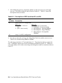
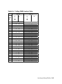
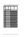
Setting Environment Variables.............................................................................. 6-5
Setting Automatic Booting .................................................................................. 6-14
Setting the Operating System to Auto Start.................................................. 6-14
Changing the Default Boot Device ...................................................................... 6-15
Setting SRM Security .......................................................................................... 6-16
Configuring Devices............................................................................................ 6-19
CPU Location ............................................................................................... 6-20
Memory Configuration ................................................................................. 6-21
PCI Configuration and Installation............................................................... 6-25
Booting Linux...................................................................................................... 6-28
Chapter 7
7.1
7.2
7.2.1
7.3
7.4
7.5
7.6
7.6.1
7.6.2
7.6.3
7.7
7.8
7.9
7.10
7.11
7.12
8.3.1
8.4
8.5
viii
Using the Remote Management Console
RMC Overview...................................................................................................... 7-2
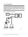
Operating Modes ................................................................................................... 7-4
Bypass Modes................................................................................................. 7-6
Terminal Setup ...................................................................................................... 7-9
SRM Environment Variables for COM1 ............................................................. 7-10
Entering the RMC................................................................................................ 7-11
Using the Command-Line Interface..................................................................... 7-13
Displaying the System Status ....................................................................... 7-14
Displaying the System Environment ............................................................ 7-18
Using Power On and Off, Reset, and Halt Functions ................................... 7-19
Configuring Remote Dial-In................................................................................ 7-21
Configuring Dial-Out Alert ................................................................................. 7-25
RMC Firmware Update and Recovery ................................................................ 7-29
Resetting the RMC to Factory Defaults............................................................... 7-32
RMC Command Reference.................................................................................. 7-35
Troubleshooting Tips........................................................................................... 7-44
Chapter 8
8.1
8.2
8.2
System Configuration and Setup
FRU Removal and Replacement
Overview of FRU Procedures................................................................................ 8-1
Important Information before Replacing FRUs ..................................................... 8-4
Important Information before Replacing FRUs ..................................................... 8-4
Recommended Spares............................................................................................ 8-5
Power Cords ................................................................................................... 8-7
FRU Locations....................................................................................................... 8-8
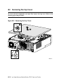
Removing the Top Cover..................................................................................... 8-10
8.6
8.7
8.8
8.9
8.10
8.11
8.12
8.13
8.14
8.15
8.16
8.17
8.18
8.19
8.20
8.21
8.21.1
8.21.2
8.22
8.23
8.24
8.25
8.26
8.27
Removing the Side Panel..................................................................................... 8-12
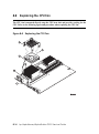
Replacing the PCI Fan ......................................................................................... 8-14
Replacing the CPU Fan ....................................................................................... 8-16
Replacing the Disk in Center Internal Storage Bay ............................................. 8-18
Replacing a Front Access Drive .......................................................................... 8-22
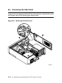
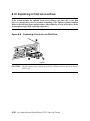
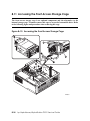
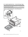
Accessing the Front Access Storage Cage........................................................... 8-26
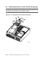
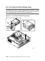
Accessing the Internal Storage Cage ................................................................... 8-28
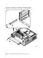
Replacing or Installing a PCI Option Module ..................................................... 8-30
Replacing the PCI Riser Card.............................................................................. 8-34
Replacing Bottom Drive – Front Access Storage Cage ....................................... 8-36
Replacing Bottom Drive – Internal Storage Cage ............................................... 8-39
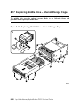
Replacing Middle Drive – Internal Storage Cage................................................ 8-41
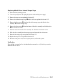
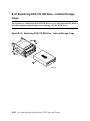
Replacing DVD/CD-RW Drive – Internal Storage Cage .................................... 8-43
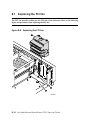
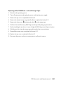
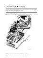
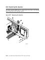
Replacing the Power Supply................................................................................ 8-45
Replacing the System Fan ................................................................................... 8-49
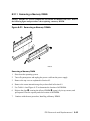
Removing or Installing a Memory DIMM........................................................... 8-51
Removing a Memory DIMM........................................................................ 8-54
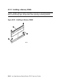
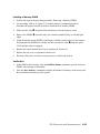
Installing a Memory DIMM ......................................................................... 8-55
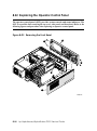
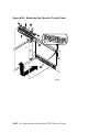
Replacing the Operator Control Panel ................................................................. 8-57
Replacing the Speaker ......................................................................................... 8-61
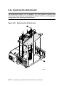
Preparing to Replace the Motherboard ................................................................ 8-63
Removing Intervening Components .................................................................... 8-64
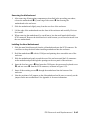
Replacing the Motherboard ................................................................................. 8-69
Reinstalling System Components ........................................................................ 8-71
Appendix A
A.1
A.2
A.2.1
A.2.2
A.2.3
A.3
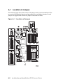
Location of Jumpers ............................................................................................. A-2
Function of Jumpers ............................................................................................. A-3
System Jumpers ............................................................................................. A-3
Server Management Jumpers......................................................................... A-4
Jumper for COM1 Pass through Enable ........................................................ A-5
Setting Jumpers..................................................................................................... A-6
Appendix B
B.1
B.2
B.3
Jumpers on System Motherboard
Isolating Failing DIMMs
Information for Isolating Failures......................................................................... B-2
DIMM Isolation Procedure................................................................................... B-3
EV68 Single-Bit Errors....................................................................................... B-12
Examples
Example 2–1 Memory Sizing........................................................................................... 2-12
Example 2–2 Running LFU ............................................................................................. 2-18
ix
Example 3–1 Sample Power-Up Display........................................................................... 3-5
Example 3–2 Power-Up Display........................................................................................ 3-8
Example 3–3 Sample Console Event Log........................................................................ 3-10
Example 3–4 Using the Log Command to Check for Errors ............................................ 3-11
Example 3–5 Checksum Error and Fail-Safe Boot Console ............................................ 3-13
Example 3–6 Report for Illegal DIMM............................................................................ 3-15
Example 3–7 Report for Missing DIMM......................................................................... 3-15
Example 3–8 Report for Incompatible DIMM................................................................. 3-16
Example 3–9 Report for Failed DIMM............................................................................ 3-16
Example 4–1 Buildfru Command ...................................................................................... 4-4
Example 4–2 more el ......................................................................................................... 4-8
Example 4–3 clear_error.................................................................................................... 4-9
Example 4–4 deposit and examine................................................................................... 4-11
Example 4–5 exer ............................................................................................................ 4-15
Example 4–6 grep ............................................................................................................ 4-20
Example 4–7 hd ............................................................................................................... 4-22
Example 4–8 info 0 .......................................................................................................... 4-25
Example 4–9 info 1 .......................................................................................................... 4-26
Example 4–10 info 2 ........................................................................................................ 4-27
Example 4–11 info 3 ........................................................................................................ 4-28
Example 4–12 info 4 ........................................................................................................ 4-29
Example 4–13 info 5 ........................................................................................................ 4-31
Example 4–14 info 6 ........................................................................................................ 4-35
Example 4–15 info 7 ........................................................................................................ 4-37
Example 4–16 info 8 ........................................................................................................ 4-38
Example 4–17 kill and kill_diags..................................................................................... 4-39
Example 4–18 memexer................................................................................................... 4-40
Example 4–19 memtest.................................................................................................... 4-42
Example 4–20 net -ic and net -s....................................................................................... 4-47
Example 4–21 nettest ....................................................................................................... 4-49
Example 4–22 set sys_serial_num ................................................................................... 4-52
Example 4–23 show error ................................................................................................ 4-53
Example 4–24 show fru ................................................................................................... 4-55
Example 4–25 show _status............................................................................................. 4-58
Example 4–26 sys_exer ................................................................................................... 4-60
Example 4–27 test -lb ...................................................................................................... 4-62
Example 6–1 Set Password .............................................................................................. 6-16
Example 6–2 set secure.................................................................................................... 6-17
Example 6–3 clear password............................................................................................ 6-18
Example 6–4 Linux Boot Output ..................................................................................... 6-29
Example 7–1 Dial-In Configuration................................................................................. 7-21
Example 7–2 Unsetting the Password.............................................................................. 7-24
Example 7–3 Dial-Out Alert Configuration..................................................................... 7-25
x
Example 7–4 Loadable Firmware Update Utility ............................................................ 7-30
Figures
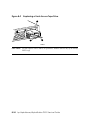
Figure 1–1 DS15 Rackmounted and Pedestal System ........................................................ 1-2
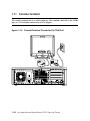
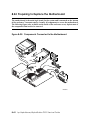
Figure 1–2 DS15 Desktop System with Internal Storage Cage Option ............................. 1-3
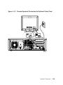
Figure 1–3 DS15 Desktop System with Front Access Storage Cage Option ...................... 1-4
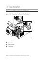
Figure 1–4 Front View with Optional Front Access Storage Cage..................................... 1-6
Figure 1–5 Top View .......................................................................................................... 1-8
Figure 1–6 Rear Ports and Slots........................................................................................ 1-10
Figure 1–7 Ethernet Network Connection ........................................................................ 1-12
Figure 1–8 Network LED indicators................................................................................. 1-13
Figure 1–9 Operator Control Panel ................................................................................... 1-14
Figure 1–10 System Motherboard.................................................................................... 1-16
Figure 1–11 Slots on the PCI Riser Card ......................................................................... 1-18
Figure 1–12 Internal Storage Cage Configuration ........................................................... 1-20
Figure 1–13 Front Access Storage Cage Configuration................................................... 1-22
Figure 1–14 Console Terminal Connected to COM Port................................................. 1-24
Figure 1–15 Console Terminal Connected to Optional Video Card ................................ 1-25
Figure 1–16 Connecting the Power for the Desktop ........................................................ 1-26
Figure 1–17 Connecting the Power for a Rackmount System ......................................... 1-27
Figure 1–18 System Access Lock ..................................................................................... 1-28
Figure 2–1 LED Patterns during Power-Up....................................................................... 2-5
Figure 2–2 FSB Switch "On" Setting............................................................................... 2-17
Figure 3–1 Power-Up Sequence......................................................................................... 3-4
Figure 3–2 FSB Switch "On" Setting (Rackmounted Orientation).................................. 3-18
Figure 3–3 Location of Floppy Device Connector........................................................... 3-20
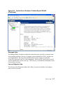
Figure 5–1 System Event Analyzer Initial Screen ............................................................. 5-4
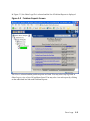
Figure 5–2 Problem Reports Screen .................................................................................. 5-5
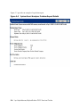
Figure 5–3 System Event Analyzer Problem Report Details ............................................. 5-6
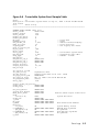
Figure 5–4 Correctable System Event Sample Table......................................................... 5-9
Figure 6–1 CPU Location ................................................................................................ 6-20
Figure 6–2 Stacked and Unstacked DIMMs .................................................................... 6-22
Figure 6–3 Memory Configuration .................................................................................. 6-24
Figure 6–4 Slots on the PCI Riser Card ........................................................................... 6-27
Figure 7–1 Data Flow in Through Mode ........................................................................... 7-4
Figure 7–2 Data Flow in Bypass Mode.............................................................................. 7-6
Figure 7–3 Setup for RMC with VT Terminal................................................................... 7-9
Figure 7–4 Setup for RMC with VGA Monitor ................................................................. 7-9
Figure 7–5 RMC Jumpers (Default Positions)................................................................. 7-34
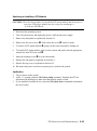
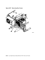
Figure 8–1 FRU Locations: Front and Top........................................................................ 8-8
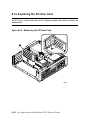
Figure 8–2 Removing the Top Cover............................................................................... 8-10
Figure 8–3 Removing the Side Panel............................................................................... 8-12
Figure 8–4 Replacing the PCI Fan ................................................................................... 8-14
xi
Figure 8–5 Replacing the CPU Fan ................................................................................. 8-16
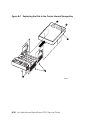
Figure 8–6 Accessing the Center Internal Storage Bay ................................................... 8-18
Figure 8–7 Replacing the Disk in the Center Internal Storage Bay ................................. 8-20
Figure 8–8 Replacing a Front Access Disk Drive........................................................... 8-22
Figure 8–9 Replacing a Front Access Tape Drive .......................................................... 8-24
Figure 8–10 Accessing the Front Access Storage Cage................................................... 8-26
Figure 8–11 Accessing the Internal Storage Cage ........................................................... 8-28
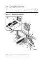
Figure 8–12 Slots on the PCI Riser Card ......................................................................... 8-31
Figure 8–13 Replacing or Installing a PCI Option Module ............................................. 8-32
Figure 8–14 Replacing the PCI Riser Card...................................................................... 8-34
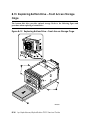
Figure 8–15 Replacing Bottom Drive – Front Access Storage Cage ............................... 8-37
Figure 8–16 Replacing Bottom Drive – Internal Storage Cage ....................................... 8-39
Figure 8–17 Replacing Middle Drive – Internal Storage Cage........................................ 8-41
Figure 8–18 Replacing DVD/CD-RW Drive – Internal Storage Cage ............................ 8-43
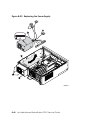
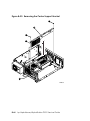
Figure 8–19 Removing Connectors from the Power Supply............................................ 8-45
Figure 8–20 Replacing the Power Supply........................................................................ 8-47
Figure 8–21 Replacing the System Fan............................................................................ 8-49
Figure 8–22 Locations for DIMMs on the Motherboard .................................................. 8-52
Figure 8–23 Removing a Memory DIMMs ..................................................................... 8-54
Figure 8–24 Installing a Memory DIMM ........................................................................ 8-55
Figure 8–25 Removing the Front Bezel ........................................................................... 8-57
Figure 8–26 Replacing the Operator Control Panel ......................................................... 8-59
Figure 8–27 Replacing the Speaker ................................................................................. 8-61
Figure 8–28 Components Connected to the Motherboard ............................................... 8-63
Figure 8–29 Removing Rear Screws................................................................................ 8-65
Figure 8–30 Removing the Center Support Bracket ........................................................ 8-67
Figure 8–31 Replacing the Motherboard ......................................................................... 8-69
Figure A–1 Locations of Jumpers ..................................................................................... A-2
xii
Tables
Table 1–1 How Physical I/O Slots Map to Logical Slots................................................. 1-19
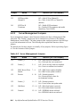
Table 2–1 Error Beep Codes .............................................................................................. 2-4
Table 2–2 OCP Switches .................................................................................................... 2-5
Table 2–3 OCP LED Indications ....................................................................................... 2-6
Table 2–4 Power Problems ................................................................................................ 2-7
Table 2–5 Problems Getting to Console Mode .................................................................. 2-8
Table 2–6 Problems Reported by the Console ................................................................... 2-9
Table 2–7 Boot Problems................................................................................................. 2-10
Table 2–8 Errors Reported by the Operating System....................................................... 2-11
Table 2–9 Memory Testing.............................................................................................. 2-12
Table 3–1 Error Beep Codes ............................................................................................ 3-12
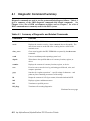
Table 4–1 Summary of Diagnostic and Related Commands.............................................. 4-2
Table 4–2 Show Error Message Translation .................................................................... 4-56
Table 5–1 DS15 Fault Detection and Correction ............................................................. 5-15
Table 5–2 Machine Checks/Interrupts ............................................................................. 5-16
Table 5–3 Sample Error Log Event Structure Map.......................................................... 5-18
Table 6–1 SRM Environment Variables ............................................................................ 6-7
Table 6-2 Comparison of Physical and Logical Slot Numbering...................................... 6-25
Table 6–3 How Physical I/O Slots Map to Logical Slots................................................. 6-26
Table 7–1 Status Command Fields .................................................................................. 7-15
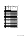
Table 7–2 Modem Initialization Commands.................................................................... 7-24
Table 7–3 Elements of Dial String and Alert String ........................................................ 7-28
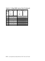
Table 7–4 DS15 initialization commands with MODEMDEF enabled ........................... 7-38
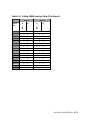
Table 7–5 RMC Troubleshooting .................................................................................... 7-44
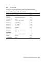
Table 8–1 Recommended Spares ....................................................................................... 8-5
Table 8–2 Optional Disk and Tape Drives......................................................................... 8-6
Table 8–3 Country-Specific Power Cords ......................................................................... 8-7
Table 8–4 DIMM and Array Reference ........................................................................... 8-52
Table A–1 Jumpers for System-Level Functions .............................................................. A-3
Table A–2 Server Management Jumpers .......................................................................... A-4
Table A–3 Jumper to Enable COM1 Pass through Mode ................................................. A-5
Table B–1 Information Needed to Isolate Failing DIMMs ............................................... B-2
Table B–2 Determining the Real Failed Array for 2-Way Interleaving............................ B-3
Table B–3 Description of DPR Locations 80, and 84 ....................................................... B-4
Table B–4 Failing DIMM Lookup Table.......................................................................... B-5
Table B–5 Syndrome to Data Check Bits Table ............................................................. B-12
Index
xiii
Preface
Intended Audience
This manual is for service providers and self-maintenance customers for AlphaServer DS15
systems.
Document Structure
This manual uses a structured documentation design. Topics are organized into small
sections, usually consisting of two facing pages. Most topics begin with an abstract that
provides an overview of the section, followed by an illustration or example. The facing
page contains descriptions, procedures, and syntax definitions.
This manual contains eight chapters and two appendixes.
•
Chapter 1, System Overview, provides an overview of the system.
•
Chapter 2, Troubleshooting, describes the starting points for diagnosing problems on
AlphaServer DS15 systems and also provides information resources.
•
Chapter 3, Power-Up Diagnostics and Display, explains the power-up process and
RMC, SROM, and SRM power-up diagnostics.
•
Chapter 4, SRM Console Diagnostics, describes troubleshooting with the SRM
console.
•
Chapter 5, Error Logs, explains how to interpret error logs reported by the operating
system.
•
Chapter 6, System Configuration and Setup, describes how to configure and set up a
DS15 system.
•
Chapter 7, Using the Remote Management Console, explains how to manage the
system through the remote management console (RMC).
•
Chapter 8, FRU Removal and Replacement, describes the procedures for removing
and replacing Field Replaceable Units (FRUs) on AlphaServer DS15 systems.
•
Appendix A, Jumpers on System Motherboard, provides detailed information on the
configuration of jumpers on the system motherboard
xv
•
Appendix B, Isolating Failing DIMMs, explains how to manually isolate a failing
DIMM from the failing address and failing data bits.
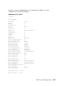
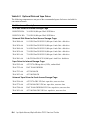
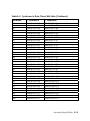
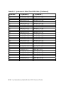
Documentation Titles
hp AlphaServer DS15 and AlphaStation DS15 Documentation
Title
Order Number
User Documentation Kit
QA-72XAA-G8
DS15 AlphaServer and DS15 AlphaStation
Owner’s Guide
EK–DS150–OG
AlphaServer DS15 Quick Setup
EK–DS150–IG
AlphaServer DS15 Floor Stand Kit
EK–DS150–FS
DS15 AlphaServer and DS15 AlphaStation
Service Guide
EK–DS150–SG
CD-ROM Installation Guide
EK–DS152–CD
AlphaServer DS15 Release Notes
EK–DS150–RN
Information on the Internet
Visit the AlphaServer Web site at http://h18002.www1.hp.com/alphaserver/ for service tools
and more information about the AlphaServer DS15 and AlphaStation DS15 system.
xvi
Chapter 1
System Overview
This chapter provides an overview of the system including:
•
System Enclosure Configurations
•
Common Components
•
Front View
•
Top View
•
Rear Ports and Slots
•
Network Connection
•
Operator Control Panel
•
System Motherboard
•
PCI Slots
•
Storage Cage Options
•
Console Terminal
•
Power Connection
•
System Access Lock
System Overview
1-1
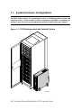
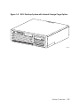
1.1
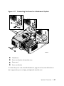
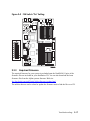
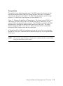
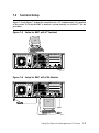
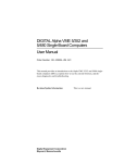
System Enclosure Configurations
The DS15 family consists of a rackmounted system, a standalone pedestal system, and
a desktop system. All have similar features, components, capabilities and options; the
desktop system will be shown throughout this manual in illustrations and examples.
Figure 1–1 DS15 Rackmounted and Pedestal System
hp
hp
hp
hp
hp
hp
hp
Alp
haSer
Alp
haSer
Alp
haSer
Alp
haSer
Alp
haSer
Alp
haSer
Alp
haSer
ver
ver
ver
ver
ver
ver
ver
DS15
DS15
DS15
DS15
DS15
DS15
DS15
hp AlphaServer DS15
MR0496
1-2
hp AlphaServer/AlphaStation DS15 Service Guide
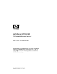
Figure 1–2 DS15 Desktop System with Internal Storage Cage Option
hp Alph
aServe
r DS15
MR0497B
System Overview
1-3
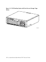
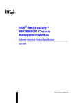
Figure 1–3 DS15 Desktop System with Front Access Storage Cage
Option
hp Alph
aServe
r DS15
MR0497A
1-4
hp AlphaServer/AlphaStation DS15 Service Guide
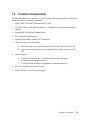
1.2
Common Components
The basic building block of AlphaServer DS15 systems is the system enclosure chassis that
houses the following common components.
•
Alpha 1 GHz CPU with 2 MB onboard ECC cache
•
512-MB, 1 GB, or 2 GB SDRAM memory − expandable to 4 GB maximum memory
capacity
•
Onboard dual 10/100 BaseT Ethernet ports
•
Four 64-bit PCI expansion slots
•
Onboard Dual Channel Ultra160 SCSI controller
•
Choice of storage cage subsystems:
•
a.
Internal Storage Cage with a maximum SCSI storage capacity of 218.4 GB
b.
Front Access Storage Cage with a maximum SCSI storage capacity of 510.4
GB
Two serial ports:
a.
COM1 port with RMC port with modem control and a full-duplex
asynchronous communications port
b.
COM2 port with full-duplex asynchronous communications port
•
PS/2-style keyboard port and mouse port
•
400W (120/240V, 60/50 Hz) power supply
System Overview
1-5
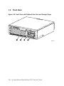
1.3
Front View
Figure 1–4 Front View with Optional Front Access Storage Cage
hp Alph
aServe
r DS15
1
2
3
4
MR0497
1-6
hp AlphaServer/AlphaStation DS15 Service Guide
X
Center internal storage bay
Y
DVD/CD-RW drive
Z
Disk storage
[
Operator control panel
System Overview
1-7
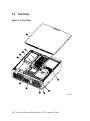
1.4
Top View
Figure 1–5 Top View
11
5
6
7
8
hp
Alp
h
aSe
rve
rD
S1
5
4
9
10
3
1
2
MR0499
1-8
hp AlphaServer/AlphaStation DS15 Service Guide
X
Operator Control Panel
Y
DVD/CD-RW drive
Z
Internal disk drive
[
Power supply
\
PCI riser
]
CPU
^
System motherboard
_
Memory
`
Speaker (hidden)
a
Center internal storage bay
Cover
System Overview
1-9
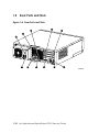
1.5
Rear Ports and Slots
Figure 1–6 Rear Ports and Slots
4
3
5
2
1
1
2
11
10
9
B
8
A
7
6
MR0498A
1-10
hp AlphaServer/AlphaStation DS15 Service Guide
X
Power supply ground
Y
Key
Z
Mouse connector
[
PCI Slots
\
Ethernet port B
]
Ethernet port A
^
Cable run hook
_
SCSI connector
`
Keyboard connector
a
COM 1 serial port (top), COM 2 serial port (bottom)
Power connector
System Overview
1-11
1.6
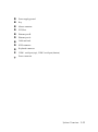
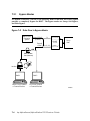
Network Connections
There are two onboard Ethernet network connectors on the rear of the DS15 system.
The DS15 system has dual onboard 10/100 BaseT Ethernet ports. You can connect to either
or both.
Figure 1–7 Ethernet Network Connection
Connect the Ethernet cable X to either Ethernet connector A Y or B Z.
1-12
hp AlphaServer/AlphaStation DS15 Service Guide
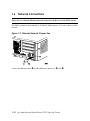
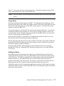
Figure 1–8 Network LED indicators
The LEDs to the left of each Ethernet connector indicate its status.
X LED Speed/Activity; indicates activity through the connection.
Y LED Link indicator; network connection exists when this is lit.
System Overview
1-13
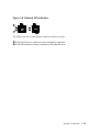
1.7
Operator Control Panel
The control panel provides system controls and status indicators. The controls are the
Power and Halt/Reset buttons. The panel has a green power LED, a green disk
activity indicator LED, and three amber diagnostic LEDs.
Figure 1–9 Operator Control Panel
1
2
3
4
5
6
7
hp Alph
aServe
r DS15
MR0500
1-14
hp AlphaServer/AlphaStation DS15 Service Guide
X
Halt/Reset button
Y
Amber system fault LED
Z
Amber over temperature fault LED
[
Amber fan fault LED
\
Green disk activity LED
]
Green system power LED
^
System Power Switch (On/Off)
NOTE:
Jumper J22 (pins 13 – 14) must be installed for the halt/reset button to function as
a reset button.
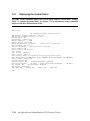
1.7.1
Remote Commands
Commands issued from the remote management console (RMC) can be used to reset, halt,
and power the system on or off. For information on RMC, see Chapter 7.
RMC
Command
Function
Power on
Turns on power. Emulates pressing the Power button to the On
position.
Power off
Turns off power. Emulates pressing the Power button to the Off
position.
Halt
Halts the system.
Halt in
Halts the system and causes the halt to remain asserted.
Halt out
Releases a halt created with halt in.
Reset
Resets the system.
System Overview
1-15
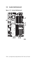
1.8
System Motherboard
Figure 1–10 System Motherboard
1-16
hp AlphaServer/AlphaStation DS15 Service Guide
X
CPU
Y
Internal SCSI connector
Z
IDE connector
[
Memory DIMM slot - array 2, DIMM 2
\
Memory DIMM slot - array 0, DIMM 0
]
Memory DIMM slot - array 2, DIMM 3
^
Memory DIMM slot - array 0, DIMM 1
_
Slot for PCI riser
1.8.1
CPU
The CPU microprocessor is a superscalar pipelined processor packaged in a
675-pin LGA carrier. The CPU has the ability to issue up to four instructions during each
CPU clock cycle and a peak instruction execution rate of four times the CPU clock
frequency.
1.8.2
DIMMS
The AlphaServer DS15 system supports up to two pairs of 200-pin synchronous DIMMs.
Supported DIMM sizes are 256 MB, 512 MB, and 1 GB, allowing memory to be configured
from 512 MB to 4096 MB.
1.8.3
PCI
The AlphaServer DS15 system supports two PCI busses, one for the onboard integrated I/O
and the other controls the four expansion slots through the PCI riser card.
System Overview
1-17
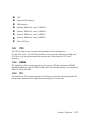
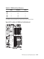
1.9
Slots on the PCI Riser Card
Figure 1–11 Slots on the PCI Riser Card
5
4
3
2
1
MR0502C
1-18
hp AlphaServer/AlphaStation DS15 Service Guide
X
Slot 1 – 66/33 MHz, 3.3v
Y
Slot 2 – 66/33 MHz, 3.3v
Z
Slot 3 – 33 MHz, 3.3v
[
Slot 4 – 33 MHz, 3.3v
r
LED – connected to +5 VAUX
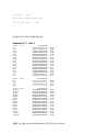
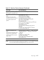
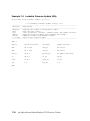
Table 1–1 How Physical I/O Slots Map to Logical Slots
Port
Hose
Physical Slot
SRM Logical Slot
A
2
1
7
2
8
3
9
4
10
System Overview
1-19
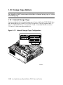
1.10 Storage Cage Options
The AlphaServer DS15 system comes with either an internal storage cage or a front
access storage cage.
1.10.1 Internal Storage Cage
Systems configured with an internal storage cage includes a half-height DVD/CD-RW drive
and a half-height bay for a disk, DVD/CD-RW, or tape drive. The cage supports three 3.5inch x 1-inch hard disk drives or two internal 3.5 inch x 1-inch hard disk drives and one
5.25-inch x 1.6-inch removable media device.
Figure 1–12 Internal Storage Cage Configuration
2
1
3
4
15
DS
er
Serv
ha
Alp
hp
MR0548A
1-20
hp AlphaServer/AlphaStation DS15 Service Guide
X
Center internal storage bay
Y
DVD/CD-RW drive
Z
DVD/CD-RW or internal drive bay (disk or tape)
[
Internal drive bay
System Overview
1-21
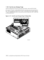
1.10.2 Front Access Storage Cage
Systems configured with a front access storage cage includes a slim-line DVD/CD-RW
drive and two 3.5-inch x 1-inch hard disk drive bays or one front access universal tape drive
bay. The cage supports two front access 3.5-inch x 1-inch hard disk drives and two internal
3.5-inch x 1-inch hard disk drives or one front access universal tape drive (AIT or DAT) and
two internal disk drives.
Figure 1–13 Front Access Storage Cage Configuration
2
3
1
4
5
15
DS
er
Serv
ha
Alp
hp
MR0549A
1-22
hp AlphaServer/AlphaStation DS15 Service Guide
X
Center internal storage bay
Y
DVD/CD-RW drive
Z
Universal drive bay
[
Universal drive bay
\
Internal drive bay
System Overview
1-23
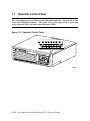
1.11 Console Terminal
The console terminal can be a serial (character cell) terminal connected to the COM1
port or a VGA monitor connected to a VGA adapter.
Figure 1–14 Console Terminal Connected to COM Port
1
B
A
2
MR0508A
1-24
hp AlphaServer/AlphaStation DS15 Service Guide
Figure 1–15 Console Terminal Connected to Optional Video Card
1
B
A
2
MR0508B
System Overview
1-25
1.12 Power Connection
Figure 1–16 shows the power connection for a desktop system.
Figure 1–16 Connecting the Power for the Desktop
2
1
1
2
3
B
MR0504B
X
Power cord
Y
Power receptacle
Z
Ground screw
1-26
hp AlphaServer/AlphaStation DS15 Service Guide
Figure 1–17 Connecting the Power for a Rackmount System
1
2
3
4
1
2
B
3
MR0504A
X
Thumbscrew
Y
Power cord bracket with attached screw
Z
Power cord
[
Power cord bracket
To connect the power cord, loosen the thumbscrew, plug the cord in, rotate the bracket so
that it supports the power cord plug, and tighten the attached screw.
System Overview
1-27
1.13 System Access Lock
The system enclosure has a key lock n for security, as shown in the figure. If you wish
to limit access to the inside of the enclosure, keep the system locked and the key in a
secure location.
Figure 1–18 System Access Lock
1
1
2
B
MR0507A
1-28
hp AlphaServer/AlphaStation DS15 Service Guide
Chapter 2
Troubleshooting
This chapter describes the starting points for diagnosing problems on AlphaServer DS15
systems. The chapter also provides information resources.
•
Questions to Consider
•
Diagnostic Categories
•
Fail-Safe Booter Utility
•
Updating Firmware
•
Service Tools and Utilities
•
Q-Vet Installation Verification
•
Information Resources
Troubleshooting
2-1
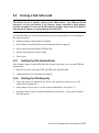
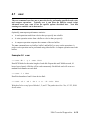
2.1
Questions to Consider
Before troubleshooting any system problem, first check the site maintenance log for the
system's service history.
Be sure to ask the system manager the following questions:
•
Has the system been used and did it work correctly?
•
Have changes to hardware or updates to firmware or software been made to the system
recently? If so, are the revision numbers compatible for the system? (Refer to the
system release notes.)
•
What is the current state of the system?
2-2
o
If the operating system is down, but you are able to access the SRM console, use
the console environment diagnostic tools, including the Operator Control Panel
(OCP) LEDs and SRM commands.
o
If you are unable to access the SRM console, enter the Remote Management
Console (RMC) command-line interface (CLI) and issue commands to determine
the hardware status. See Chapter 7.
o
If the operating system has crashed and rebooted, the Computer Crash Analysis
Tool (CCAT), the System Event Analyzer service tools (to interpret error logs), the
SRM crash command, and operating system exercisers can be used to diagnose
system problems.
hp AlphaServer/AlphaStation DS15 Service Guide
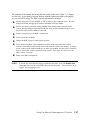
2.2
Diagnostic Categories
System problems can be classified into the following categories. Using these categories,
you can quickly determine a starting point for diagnosis and eliminate the unlikely
sources of the problem.
The next several subsections group problems into one of several categories.
•
Error beep codes
•
Diagnostic LEDs on the OCP
•
Power problems
•
Problems getting to the console mode
•
Problems reported by the console mode
•
Boot problems
•
Errors reported by the operating system
•
Memory problems
•
PCI bus problems
•
SCSI problems
•
Thermal problems and environmental status
WARNING:
To prevent injury, access is limited to persons who have
appropriate technical training and experience. Such persons are expected to
understand the hazards of working within this equipment and take measures to
minimize danger to themselves or others. These measures include:
1. Remove any jewelry that may conduct electricity.
2. If accessing the system card cage, power down the system
and wait 2 minutes to allow components to cool.
3. Wear an anti-static wrist strap when handling internal
components.
Troubleshooting
2-3
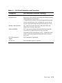
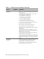
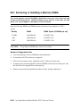
2.2.1
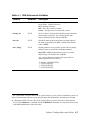
Error Beep Codes
Audible beep codes announce specific errors that might be encountered while the
system is powering up. Table 2–1 identifies the error beep codes.
Table 2–1 Error Beep Codes
Beeps Message/Meaning
Action to Repair
1
Done with execution; jumping to console
No action necessary.
1-3-3
No usable memory available
Check memory and memory
configuration.
2-1-2
Configuration error detected
Check system configurations.
1-1-4
ROM checksum error detected
Replace the system board.
1-2-4
Bcache error detected
Possible CPU problem.
2-4
hp AlphaServer/AlphaStation DS15 Service Guide
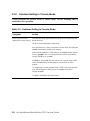
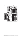
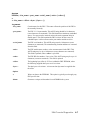
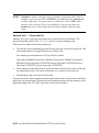
2.2.2
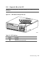
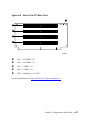
Diagnostic LEDs on the OCP
Diagnostic LEDs on the operator control panel indicate error conditions and power-up
information.
Figure 2–1 LED Patterns during Power-Up
1
2
3
4
5
6
7
hp Alph
aServe
r DS15
MR0500
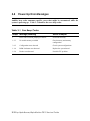
Table 2–2 OCP Switches
Switch
X
^
Function
Halt/Reset
System Power Switch (On/Off)
Troubleshooting
2-5
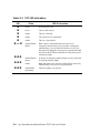
Table 2–3 OCP LED Indications
LED
]
\
[
Z
Y
o and q
YZ[
opq
opq
2-6
Color
LED On Function
Green
System power is on.
Green
There is disk activity.
Amber
There is a fan fault.
Amber
The system is over temperature.
Amber
There is a system fault.
Amber/blink in
unison
RMC image is corrupted but the system is not in
emergency runtime image recovery mode or emergency
runtime image recovery mode has timed out. If recovery
has timed out, unplug the system power cord and wait until
the LED on the PCI Riser card turns off. Plug in the power
cord and try again.
Amber/blink in
unison
System is in emergency runtime image recovery mode and
is awaiting firmware update.
Amber
RMC has failed or the system is configured for emergency
runtime image recovery but is not powered on.
Amber/blink
sequentially
Firmware update is in progress.
hp AlphaServer/AlphaStation DS15 Service Guide
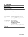
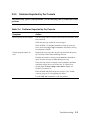
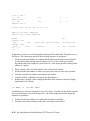
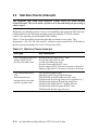
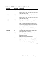
2.2.3
Power Problems
Power problems can prevent the system from operating. Use the following table to
troubleshoot these problems.
Table 2–4 Power Problems
If the power indicator is:
Check:
Off
Front-panel power switch
Power at the wall receptacle
AC cord
Power cable connectors
Unplug the power cord for 15 seconds, then reconnect.
On for a few seconds and then
goes Off
Enter the RMC. Use the poe command to check for poweron
errors, and use the log or log # command to check the event log
for symptoms of failure.
Make sure that all jumpers are in their default state.
On, but the monitor screen is
black for approximately 40
seconds and then turns blue.
Monitor power indicator is On.
Video cable is properly connected.
SRM console environment variable setting.
EV may not be set to graphics.
NOTE: A black raster is displayed if the console environment
variable is set to serial mode rather than graphics mode.
Off and system does not power
on remotely via RMC
Front panel switch is in the On (depressed) position.
Troubleshooting
2-7
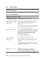
2.2.4
Problems Getting to Console Mode
Certain problems can prevent access to console mode. Use the following table to
troubleshoot these problems.
Table 2–5 Problems Getting to Console Mode
Symptom
Action
Power-up screen is not
Note any error beep codes and observe the OCP for a failure detected
displayed at system console. during self-tests.
Check keyboard and monitor connections.
Press the Return key. If the system enters console mode, check that the
console environment variable is set correctly.
If the console terminal is a VGA monitor, the console variable should
be set to graphics. If it is a serial terminal, the console environment
variable should be set to serial.
If console is set to serial, the power-up screen is routed to the COM1
serial communication port and cannot be viewed from the VGA
monitor.
Try connecting a console terminal to the COM2 serial communication
port. When using the COM2 port set the console environment
variable to serial.
Use RMC commands to determine status.
2-8
hp AlphaServer/AlphaStation DS15 Service Guide
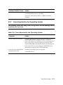
2.2.5
Problems Reported by the Console
The console may report certain problems. Use the following table to troubleshoot these
problems.
Table 2–6 Problems Reported by the Console
Symptom
Action
Power-up tests do not complete.
Use error beep codes or console serial terminal to determine what
error occurred.
Check the power-up screen for error messages.
Enter the RMC. Use the poe command to check for poweron
errors, and use the log or log # command to check the event log
for symptoms of failure.
Console program reports an
error.
Interpret the error beep codes at power-up and check the powerup screen for a failure detected during self-tests.
Examine the console event log (use the more el command) to
check for error messages recorded during power-up.
If the power-up screen or console event log indicates problems
with mass storage devices or PCI devices, or if devices are
missing from the show config or show device display, see
Section 2.2.9 and 2.2.10.
Enter the RMC and check the power-on errors “poe” and the
event log “log, log #” for symptoms for failure.
Use the SRM test command to verify the problem.
Troubleshooting
2-9
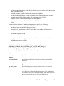
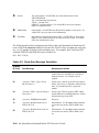
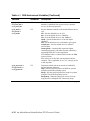
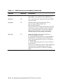
2.2.6
Boot Problems
Certain problems may interfere with the boot process. Use the following table to
troubleshoot these problems.
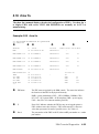
Table 2–7 Boot Problems
Problem/Possible Cause
Action
Operating system (OS) software
is not installed on the disk drive.
Install the operating system and license key.
Target boot device is not listed in Check the cables. Are the cables oriented properly and not
the SRM show device or show
cocked? Are there bent pins? Check all the SCSI devices for
config command.
incorrect or conflicting IDs. Refer to the device's
documentation.
SCSI termination: The SCSI bus must be terminated at the end
of the internal cable and at the last external SCSI peripheral.
Review the position of all relevant jumpers.
System cannot find the boot
device.
Use the SRM show config and show device commands. Use the
displayed information to identify target devices for the boot
command, and verify that the system sees all of the installed
devices. If you are attempting to use bootp, first set the
following variables as shown. (Replace ewa0 with the
appropriate device designation.)
>>>set ewa0_inet_init BOOTP
>>>set ewa0_protocols BOOTP
System does not boot.
Verify that no unsupported adapters are installed.
Environment variables are
incorrectly set.
This could happen if the main logic board has been replaced,
which would cause a loss of the previous configuration
information.
Use the SRM show and set commands to check and set the
values assigned to boot-related variables such as auto_action,
bootdef_dev, and boot_osflags.
System will not boot over the
network.
2-10
For problems booting over a network, check the
ew*0_protocols, ei*0_protocols or eg*0_protocols
environment variable settings: Systems booting from a Tru64
UNIX server should be set to bootp; systems booting from an
hp AlphaServer/AlphaStation DS15 Service Guide
Problem/Possible Cause
Action
OpenVMS server should be set to mop. Run the test command
to check that the boot device is operating.
Check ei*0_mode. Refer to Table 6-1, SRM Environment
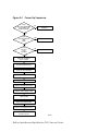
Variables.
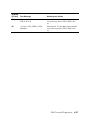
2.2.7
Errors Reported by the Operating System
The operating system may hang, crash, or log errors. Use the following table to
troubleshoot these problems.
Table 2–8 Errors Reported by the Operating System
Symptom
Action
System is hung or has crashed.
If possible, halt the system by using either the halt/reset button or
the RMC halt command. (Jumper J22 pins 13-14 must be
removed. If jumper J22 is installed, you will reset the system and
loose system context so that no crash can be acquired.) Then
enter the SRM crash command and examine the crash dump file.
Refer to the Guide to Kernel Debugging (AA-PS2TD-TE) for
information on using the Tru64 UNIX Crash utility.
Errors have been logged and the
operating system is up.
Examine the operating system error log files.
Contact HP Services.
Troubleshooting
2-11
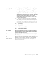
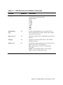
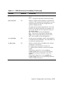
2.2.8
Memory Problems
Memory problems may affect system performance. Use the following table to
troubleshoot these problems.
Table 2–9 Memory Testing
Symptom
Action
DIMMs ignored by system, or
Ensure that each memory array has identical DIMMs installed.
system unstable. System hangs or
crashes.
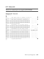
DIMMs failing memory powerup self-test.
Replace the DIMMs that the SROM has isolated on power up.
See Example 2–1.
DIMMs may not have ECC bits.
Some third-party DIMMs may not be compatible with DS15
systems. Ensure that the DIMMs are qualified.
Noticeable performance
degradation. The system may
appear hung or run very slowly.
This could be a result of hard single-bit ECC errors on a
particular DIMM. Check the error logs for memory errors.
Ensure that the memory DIMMs are qualified.
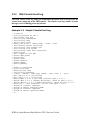
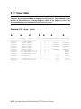
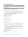
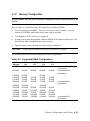
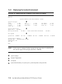
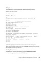
Example 2–1 Memory Sizing
Memory sizing in progress
Memory configuration in progress
Testing AAR2
Memory data test in progress
Memory data path error
ErrAdr:
Expect:
Actual:
XORval:
00000000.00000000
00000000.00000001
00000000.00000000
00000000.00000001
Testing AAR0
Memory data test in progress
Memory address test in progress
Memory pattern test in progress
Memory initialization
Failed DIMM 3
Loading console
Code execution complete (transfer control)
2-12
hp AlphaServer/AlphaStation DS15 Service Guide
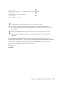
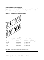
2.2.9
PCI Bus Problems
PCI bus problems at startup are usually indicated by the inability of the system to
detect the PCI device. Use the following steps to diagnose the likely cause of PCI bus
problems.
1.
Five volt PCI adapters are not allowed.
2.
Confirm that the PCI option module is supported and has the correct firmware and
software versions.
3.
Confirm that the PCI option module and any cabling are properly seated.
4.
Check for a bad PCI slot by moving the last installed PCI option module to a different
slot.
5.
Contact HP Service to replace the PCI riser card.
PCI Parity Error
Some PCI devices do not implement PCI parity, and some have a parity generating scheme
that may not comply with the PCI specification. In such cases, the device should function
properly if parity is not checked.
Parity checking can be turned off with the set pci_parity off command so that false PCI
parity errors do not result in machine check errors. However, if you disable PCI parity, no
parity checking is implemented for any device. Turning off PCI parity is therefore not
recommended or supported.
Troubleshooting
2-13
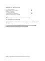
2.2.10 SCSI Problems
SCSI problems are generally manifested as data corruption, boot problems, or poor
performance.
Do the following:
•
Check SCSI bus termination and relevant SCSI jumpers.
•
Ensure that all disks have a unique ID.
•
Invoke “run bios” and check or configure SCSI devices.
•
Cable is properly seated at system board or option connector.
•
Bus must be terminated at last device on cable or at physical cable end.
•
No terminators in between.
•
Old 50-pin (narrow) devices must be connected with wide-to-narrow adapter (SN-PBXKPBA). Do not cable from the connector on the card.
•
Using 50-pin devices on the bus may significantly degrade performance.
•
Any external drives must be connected to the external port on the rear of the system or
to their associated card. These cards must have no internal drives connected to them.
•
Ultra-wide SCSI has strict bus length requirements.
•
SCSI bus itself cannot handle internal plus external cable.
•
Connection of internal SCSI drives in either the front access or internal storage cage is not
supported.
2-14
hp AlphaServer/AlphaStation DS15 Service Guide
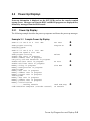
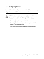
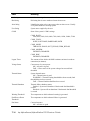
2.2.11 Thermal Problems and Environmental Status
Overtemperature conditions can cause the system to shut down.
The DS15 system operates in an ambient temperature range of 10ºC–40ºC. An internal
sensor monitors the system temperature and shuts down the system if maximum limits are
exceeded. If the system shuts down unexpectedly:
•
Ensure that the side cover (pedestal) or top cover (rack) are properly secured.
•
Verify that the ambient temperature does not exceed the specified limits.
•
Make sure there are no airflow obstructions at the front or rear of the system.
•
Check to see that the cables inside the system are properly dressed. A dangling cable can
impede airflow to the system.
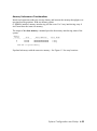
Troubleshooting with the show power Command
The SRM console show power command can help you determine if environmental
problems necessitate the replacement of a power supply, system fan or fans, or the
motherboard.
Show power indicates:
Action
Bad voltage
Replace the power supply and or the system motherboard.
Contact HP Services.
Bad fan
Replace the indicated fan or fans. Contact HP Services.
Bad temperature
The problem could be a bad fan or an obstruction to the airflow.
Check the airflow first. If there is no obstruction, contact HP
Services to replace the bad fan.
Troubleshooting with RMC Commands
The RMC status command displays the system status and the current RMC settings. See
Section 7.6.1 for more information.
The RMC env command provides a snapshot of the system environment. See Section 7.6.2
for more information.
The log command prints out a brief summary of the last 10 system events that have been
logged. Issuing the log command followed by a number (0-9) provides detailed information
about the selected system event (0 = most recent event).
Troubleshooting
2-15
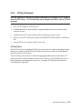
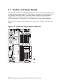
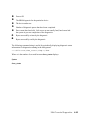
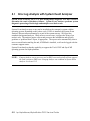
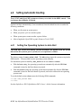
2.3
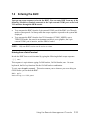
Fail-Safe Booter Utility
The fail-safe booter utility (FSB) is another variant of the SRM console. The FSB
provides an emergency recovery mechanism if the firmware image contained in flash
memory becomes corrupted. You can run the FSB and boot another image from a CDROM or network that is capable of reprogramming the flash ROM.
Use the FSB when one of the following failures at power-up prohibits you from getting to
the console program:
•
Firmware image in flash memory corrupted
•
Power failure or accidental power-down during a firmware upgrade
•
Error in the nonvolatile RAM (NVRAM) file
•
Incorrect environment variable setting
•
Driver error
2.3.1
Starting the FSB Automatically
If the firmware image is unavailable when the system is powered on or reset, the FSB runs
automatically.
1.
Reset the system to restart the FSB. The FSB loads from the flash.
2.
Update the firmware as described in Section 2.4.
2.3.2
Starting the FSB Manually
1.
Power the system off, unplug the AC power cord, and remove the cover.
2.
Insert jumper J8 over pins 1 – 2 on the system motherboard. See
Figure 2–2 for a location.
3.
Reconnect the AC power cord and reinstall the system cover.
4.
Power up the system to the FSB console.
2-16
hp AlphaServer/AlphaStation DS15 Service Guide
Figure 2–2 FSB Switch "On" Setting
2.3.3
Required Firmware
The required firmware for your system is preloaded onto the flash ROM. Copies of the
firmware files are included on your distribution CD. You can also download the latest
firmware files from the Alpha systems firmware Web site:
ftp://ftp.digital.com/pub/Digital/Alpha/firmware/readme.html
The utilities that are used to reload or update the firmware need to find the files on a CD.
Troubleshooting
2-17
2.4
Updating Firmware
Be sure to read the information on starting the FSB utility before continuing with this
section.
Updating the Console Firmware
Perform the following steps to update the console firmware. Refer to
Example 2–2.
1.
Insert the Alpha Firmware CD into the DVD/CD-RW drive.
2.
At the SRM console prompt, issue the >>>b dqa0 command.
3.
At the UPD> prompt, enter the update SRM command.
After the update has completed, enter the exit command to exit the utility.
Example 2–2 Running LFU
>>> boot dqa0
Checking dqa0.0.0.13.0 for the option firmware files. . .
dqa0.0.0.13.0 has no media present or is disabled via the RUN/STOP switch
Checking dqa1.1.0.13.0 for the option firmware files. . .
Checking dva0.0.0.1000.0 for the option firmware files. . .
Option firmware files were not found on CD or floppy.
If you want to load the options firmware,
please enter the device on which the files are located(ewa0),
or just hit <return> to proceed with a standard console update:
***** Loadable Firmware Update Utility *****
---------------------------------------------------------------------------Function
Description
---------------------------------------------------------------------------Display
Displays the system's configuration table.
Exit
Done exit LFU (reset).
List
Lists the device, revision, firmware name, and update revision.
Update
Replaces current firmware with loadable data image.
Verify
Compares loadable and hardware images.
? or Help
Scrolls this function table.
---------------------------------------------------------------------------UPD> update srm
Confirm update on:
SRM
[Y/(N)] y
WARNING: updates may take several minutes to complete for each device.
DO NOT ABORT!
SRM
2-18
Updating to X6.6-1977...
Verifying X6.6-1977...
hp AlphaServer/AlphaStation DS15 Service Guide
PASSED.
UPD> exit
Do you want to do a manual update? [y/(n)] n
UPD> list
Device
Current Revision
Filename
Update Revision
T6.6-8
T6.6-7
No Update Available
FSB
SRM
booter
T6.6-6
T6.6-7
V0.5-6
fsb_fw
srm_fw
booter_fw
rt
srom
tig
V0.6-3
V1.0-1
1.9
rt_fw
srom_fw
tig_fw
V0.6-3
V1.0-1
1.9
UPD> u fsb
Confirm update on:
FSB
[Y/(N)]y
WARNING: updates may take several minutes to complete for each device.
DO NOT ABORT!
FSB
Updating to V6.6-8...
Verifying T6.6-8...
PASSED.
UPD> exit
Initializing....
Troubleshooting
2-19
2.5
Service Tools and Utilities
This section lists some of the tools and utilities available for acceptance testing and
diagnosis and gives recommendations for their use.
2.5.1
Error Handling/Logging Tools (System Event Analyzer)
The operating systems provide fault management error detection, handling, notification, and
logging.
The primary tool for error handling is System Event Analyzer (SEA), a fault analysis utility
designed to analyze both single and multiple error/fault events. SEA uses error/fault data
sources other than the traditional binary error log. See Chapter 5 for more information.
2.5.2
Loopback Tests
Internal and external loopback tests are used to test the I/O components and adapter cards.
The loopback tests are a subset of the SRM diagnostics.
Use loopback tests to isolate problems with the COM2 serial port, the parallel port, and
Ethernet controllers. See the test command in Chapter 4 for instructions on performing
loopback tests.
2.5.3
SRM Console Commands
SRM console commands are used to set and examine environment variables and device
parameters. For example, the show configuration and show device commands are used to
examine the configuration, and the set envar and show envar commands are used to set and
view environment variables.
SRM commands are also used to invoke ROM-based diagnostics and to run native
exercisers. For example, the test and sys_exer commands are used to test the system.
See Chapter 4 for information on running console exercisers. See Chapter 6 for information
on configuration-related console commands and environment variables. See Chapter 7 for a
list of console commands used most often on AlphaServer DS15 systems.
2.5.4
Remote Management Console (RMC)
The remote management console is used for managing the server either locally or remotely.
It also plays a key role in error analysis by passing error log information to the dual-port
RAM (DPR), which is shared between the RMC and the system motherboard logic, so that
this information can be accessed by the system. RMC also controls the diagnostic LEDs on
the Operator Control Panel (OCP). RMC has a command-line interface from which you can
enter a few diagnostic commands.
2-20
hp AlphaServer/AlphaStation DS15 Service Guide
RMC can be accessed as long as the power cord for a working supply is plugged into the
AC wall outlet and a console terminal is attached to the system. This feature ensures that
you can gather information when the operating system is down and the SRM console is not
accessible. See Chapter 7.
2.5.5
Crash Dumps
For fatal errors, the operating systems save the contents of memory to a crash dump file.
This file can be used to determine why the system crashed.
The Computer Crash Analysis Tool (CCAT) is the primary crash dump analysis tool for
analyzing crash dumps on Alpha systems. CCAT compares the results of a crash dump with
a set of rules. If the results match one or more rules, CCAT notifies the system user of the
cause of the crash and provides information to avoid similar crashes in the future.
Troubleshooting
2-21
2.6
Q-Vet Installation Verification
CAUTION: Customers are not authorized to access, download, or use Q-Vet. Q-Vet is
for use by HP engineers to verify the system installation. Misuse of Q-Vet may result
in loss of customer data.
Q-Vet is the Qualification Verifier Exerciser Tool that is used by HP engineers to exercise
systems under development. HP recommends running the latest Q-Vet released version to
verify that hardware is installed correctly and is operational. Q-Vet does not verify specific
operating system or layered product configurations.
The latest Q-Vet release, information, Release Notes, and documentation are located at
http://cisweb.mro.cpqcorp.net/projects/qvet/.
HP recommends that Compaq Analyze be installed on the operating system prior to running
Q-Vet.
CAUTION:
Do not install the Digital System Verification Software (DECVET) on the system; use Q-Vet
instead.
Non-IVP Q-Vet scripts verify disk operation for some drives with "write enabled"
techniques. These are intended for Engineering and Manufacturing Test. Run ONLY IVP
scripts on systems that contain customer data or any other items that must not be written
over. See the Q-Vet Disk Testing Policy Notice on the Q-Vet Web site for details. All Q-Vet
IVP scripts use Read Only and/or File I/O to test hard drives. Floppy and tape drives are
always write tested and should have scratch media installed
Q-Vet must be de-installed upon completion of system verification.
2-22
hp AlphaServer/AlphaStation DS15 Service Guide
Swap or Pagefile Space
The system must have adequate swap space (on Tru64 UNIX) or pagefile space (on
OpenVMS) for proper Q-Vet operation. You can set this up either before or after Q-Vet
installation.
During initialization, Q-Vet will display a message indicating the minimum amount of
swap/pagefile needed, if it determines that the system does not have enough. You can then
reconfigure the system.
If you wish to address the swap/pagefile size before running Q-Vet, see the Swap/Pagefile
Estimates on the Q-Vet Web site.
Troubleshooting
2-23
2.6.1
Installing Q-Vet
The procedures for installation of Q-Vet differ between operating systems. You must
install Q-Vet on each partition in the system.
Install and run Q-Vet from the SYSTEM account on OpenVMS and the root account on
Tru64 UNIX. Remember to install Q-Vet in each partition.
Tru64 UNIX
1.
Make sure that there are no old Q-Vet or DECVET kits on the system by using the
following command:
setld -i | grep VET
Note the names of any listed kits, such as OTKBASExxx etc., and remove the kits using
qvet_uninstall if possible. Otherwise use the command
setld -d kit1_name kit2_name kit3_name
2.
Copy the kit tar file (QVET_Vxxx.tar) to your system.
3.
Be sure that there is no directory named output. If so move to another directory or
remove the output directory.
rm -r output
4.
Untar the kit with the command
tar xvf QVET_Vxxx.tar
Note: The case of the file name may be different depending upon how it was stored on
the system. Also, you may need to enclose the file name in quotation marks if a semicolon is used.
5.
Install the kit with the command
setld -l output
6.
During the install, if you intend to use the GUI you must select the optional GUI subset
(QVETXOSFxxx).
7.
The Q-Vet installation will size your system for devices and memory. It also runs
qvet_tune. You should answer 'y' to the questions that are asked about setting
parameters. If you do not, you may have trouble running
Q-Vet. After the installation completes, you should delete the output directory with rm
-r output. You can also delete the kit tar file.
8.
You must reboot the system before starting Q-Vet.
9.
On reboot you can start Q-Vet GUI via vet& or you can run nonGUI (command line)
via vet –nw.
OpenVMS
2-24
hp AlphaServer/AlphaStation DS15 Service Guide
1.
Delete any QVETAXPxxx.A or QVETAXPxxx.EXE file from the current directory.
2.
Copy the self-extracting kit image file (QVETAXPxxx.EXE) to the current directory.
3.
It is highly recommended, but not required, that you purge the system disk before
installing Q-Vet. This will free up space that may be needed for pagefile expansion
during the AUTOGEN phase.
$purge sys$sysdevice:[*…]*.*
4.
Extract the kit saveset with the command $run QVETAXPxxx.EXE and verify that
the kit saveset was extracted by checking for the "Successful decompression" message.
5.
Use @sys$update:vmsinstal for the Q-Vet installation. The installation will size
your system for devices and memory. You should choose all the default answers during
the Q-Vet installation. This will verify the Q-Vet installation, tune the system, and
reboot. During the install, if you do not intend to use the GUI, you can answer no to
the question "Do you want to install Q-Vet with the DECwindows Motif interface?"
6.
After the installation completes you should delete the QVETAXP0xx.A file and the
QVETAXPxxx.EXE file.
7.
On reboot you can start Q-Vet GUI via $vet or the command interface via
$vet/int=char.
Troubleshooting
2-25
2.6.2
Running Q-Vet
You must run Q-Vet on each partition in the system to verify the complete system.
Review the Special Notices and the Testing Notes section of the Release Notes located at
http://cisweb.mro.cpqcorp.net/projects/qvet/ before running Q-Vet.
Follow the instructions listed for your operating system to run Q-Vet in each partition.
Tru64 UNIX
Graphical Interface
Command-Line Interface
1.
From the Main Menu, select IVP, Load Script and select
Long IVP (the IVP tests will then load into the Q-Vet process
window).
2.
Click the Start All button to begin IVP testing.
> vet -nw
Q-Vet_setup> execute .Ivp.scp
Q-Vet_setup> start
Note that there is a "." in front of the script name, and that commands
are case sensitive.
2-26
hp AlphaServer/AlphaStation DS15 Service Guide
OpenVMS
Graphical Interface
Command-Line Interface
1.
From the Main Menu, select IVP, Load Script and select
Long IVP (the IVP tests will then load into the
Q-Vet process window).
2.
Click the Start All button to begin IVP testing.
$ vet /int=char
Q-Vet_setup> execute ivp.vms
Q-Vet_setup> start
Note that commands are case sensitive.
NOTE: A short IVP script is provided for a simple verification of device setup. It is
selectable from the GUI IVP menu, and the script is called .Ivp_short.scp
(ivp_short.vms). This script will run for 15 minutes and then terminate with a
Summary log. The short script may be run prior to the long IVP script if desired,
but not in place of the long IVP script, which is the full IVP test.
The long IVP will run until the slowest device has completed one pass (typically 2 to 12
hours). This is called a Cycle of Testing.
Troubleshooting
2-27
2.6.3
Reviewing Results of the Q-Vet Run
After running Q-Vet, check the results of the run by reviewing the summary log.
If you follow the above steps, Q-Vet will run all exercisers until the slowest device has
completed one full pass. Depending on the size of the system (number of CPUs and disks),
this will typically take 2 to 12 hours. Q-Vet will then terminate testing and produce a
summary log. The termination message will tell you the name and location of this file.
All exerciser processes can also be manually terminated with the Suspend and Terminate
buttons (stop and terminate commands).
After all exercisers report “Idle,” the summary log is produced containing Q-Vet specific
results and statuses.
•
If there are no Q-Vet errors, no system event appendages, and testing ran to the specified
completion time, the following message will be displayed:
”Q-Vet Tests Complete: Passed”
•
Otherwise, a message will indicate:
”Additional information may be available from System Event
Analyzer”
It is recommended that you run System Event Analyzer to review test results. The testing
times (for use with System Event Analyzer) are printed to the Q-Vet run window and are
available in the summary log.
2-28
hp AlphaServer/AlphaStation DS15 Service Guide
2.6.4
De-Installing Q-Vet
The procedures for de-installation of Q-Vet differ between operating systems. You
must de-install Q-Vet from each partition in the system. Failure to do so may result in
the loss of customer data at a later date if Q-Vet is misused.
Follow the instructions listed under your operating system to de-install Q-Vet from a
partition. The qvet_uninstall programs will remove the Q-Vet supplied tools and restore
the original system tuning/configuration settings.
Tru64 UNIX
1.
Stop, Terminate, and Exit from Q-Vet testing.
2.
Execute the command qvet_uninstall. This will also restore the system
configuration/tuning file sysconfigtab.
3.
Note: log files are retained in /usr/field/tool_logs
4.
Reboot the system. You must reboot in any case, even if Q-Vet is to be reinstalled.
OpenVMS
1.
Stop, Terminate, and Exit from any Q-Vet testing.
2.
Execute the command @sys$manager:qvet_uninstall. This will restore system tuning
(modparams.dat) and the original UAF settings.
3.
Note: log files are retained in sys$specific:[sysmgr.tool_logs]
4.
Reboot the system. You must reboot in any case, even if Q-Vet is to be reinstalled.
Troubleshooting
2-29
2.7
Information Resources
Many information resources are available, including tools that can be downloaded
from the Internet, firmware updates, a supported options list, and more.
2.7.1
HP Service Tools CD
The HP Service Tools CD-ROM enables field engineers to upgrade customer systems with
the latest version of software when the customer does not have access to HP Web pages.
The Web site is:
http://www.mse.qvar.cpqcorp.net/ServiceTools/default.asp
2.7.2
DS15 Service HTML Help File
The information contained in this guide, including the FRU procedures and illustrations, is
available in HTML Help format as part of the Maintenance Kit. It can also be accessed
from the Learning Utility and ProSIC Web sites.
2.7.3
Alpha Systems Firmware Updates
The firmware resides in the flash ROM on the system motherboard. You can obtain the
latest system firmware from CD-ROM or over the network.
Quarterly Update Service
The Alpha Systems Firmware Update Kit CD-ROM is available by subscription.
Alpha Firmware Internet Access
•
You can obtain Alpha firmware updates from the following Web site:
http://ftp.digital.com/pub/Digital/Alpha/firmware/readme.html
•
The README file describes the firmware directory structure and how to download and
use the files.
•
If you don’t have a Web browser, download the files using anonymous ftp:
ftp://ftp.digital.com/pub/Digital/Alpha/firmware/
•
Individual Alpha system firmware releases that occur between releases of the firmware CD
are located in the interim directory:
•
ftp://ftp.digital.com/pub/Digital/Alpha/firmware/interim/
2-30
hp AlphaServer/AlphaStation DS15 Service Guide
2.7.4
Fail-Safe Booter
The fail-safe booter (FSB) allows you to run another console to repair files that reside in the
flash ROMs on the system motherboard. See Chapter 3 for information on running the FSB.
2.7.5
Software Patches
Software patches for the supported operating systems are available from:
http://h18002.www1.hp.com/alphaserver/
2.7.6
Learning Utility
The Learning Utility provides information about various technical topics.
http://learning1.americas.cpqcorp.net/mcsl-html/home.asp
2.7.7
Late-Breaking Technical Information
You can download up-to-date files and late-breaking technical information from the
Internet.
The information includes firmware updates, the latest configuration utilities, software
patches, lists of supported options, and more.
http://h18002.www1.hp.com/alphaserver/
2.7.8
Supported Options
A list of options supported on the system is available on the Internet:
http://h18002.www1.hp.com/alphaserver/
Troubleshooting
2-31
Chapter 3
Power-Up Diagnostics and Display
This chapter describes the power-up process and RMC, SROM, and SRM power-up
diagnostics. The following topics are covered:
•
Overview of Power-Up Diagnostics
•
System Power-Up Sequence
•
Power-Up Displays
•
Power-Up Error Messages
•
Forcing a Fail-Safe Load
•
Updating the RMC
Power-Up Diagnostics and Display 3-1
3.1
Overview of Power-Up Diagnostics
The power-up process begins with the power-on of the power supply. After the AC and
DC power-up sequences are completed, the remote management console (RMC) reads
EEROM information and deposits it into the dual-port RAM (DPR). The SROM
minimally tests the CPU, initializes and tests backup cache, and minimally tests
memory. Finally, the SROM loads the SRM console program into memory and jumps
to the first instruction in the console program.
There are three distinct sets of power-up diagnostics:
1.
System power controller and remote management console diagnostics – These
diagnostics check the power regulators, temperature, and fans. Failures are reported in
the dual-port RAM and on the Operator Control Panel (OCP) LEDs. Certain failures
may prevent the system from powering on.
2.
Serial ROM (SROM) diagnostics – SROM tests check the basic functionality of the
system and load the console code from the FEPROM on the system motherboard into
system memory. Failures during SROM tests are indicated by error beep codes and
messages to the power-up console terminal.
3.
Console firmware diagnostics – These tests are executed by the SRM console code.
They test the core system, including boot path devices. Failures during these tests are
reported to the console terminal through the power-up screen or console event log.
3-2 hp AlphaServer/AlphaStation DS15 Service Guide
3.2
System Power-Up Sequence
The
power-up
Figure 3–1.
sequence
is
described
below
and
illustrated
in
The RMC is responsible for the power-up sequence of the AlphaServer DS15. The general
power-up sequence follows:
1.
Verify that the MLB FRU EEPROM is accessible and has a valid checksum. The
system will not be allowed to power-on unless these conditions are met (this check –
and others - can be disabled with the FEATURE_0 jumper).
2.
Verify that the RMC did not detect any system problems during its power-on self-test
(this check can be overridden with the FEATURE_0 jumper).
3.
Verify that the PCI Riser Card (PRC) is installed (this check can be disabled with the
FEATURE_3 jumper).
4.
Assert DC Enable to the bulk power supply and wait for Power OK (POK) to assert.
5.
Check the 2.5V regulator to ensure it is within specified tolerances.
6.
Check to see if the disk fan is spinning. If it is and the FEATURE_4 jumper is installed,
flag a configuration error.
7.
Release Titan Interrupt and General logic chip (TIG) from reset.
8.
Assert power-on signal to TIG.
9.
Release system from reset.
10. Wait for TIG to assert ready.
11. Wait for TIG to request 1.65V enable.
12. Assert the 1.65V VRM enable signal.
13. Wait for the 1.65V VRM Power OK signal to assert.
Power-Up Diagnostics and Display 3-3
Figure 3–1 Power-Up Sequence
verify
MLB FRU EEPROM
accessibility and
valid checksum
no
disabled
yes
verify
system problems
with
RMC
yes
disabled
no
verify
PCI riser
card
installed
no
disabled
yes
apply DC enable to
power supply
2.5V regulator
checked for tolerances
check for fan operation
release TIG from reset
apply power-on to TIG
release system from reset
wait for TIG to apply ready
wait for TIG to request
1.65V enable
apply 1.65 VRM enable
wait for 1.65 VRM power ok
RMC continues to
monitor system
MR0601
3-4 hp AlphaServer/AlphaStation DS15 Service Guide
3.3
Power-Up Displays
Power-up information is displayed on the OCP LEDs and on the console terminal
startup screen. Messages sent from the RMC and SROM programs are displayed first,
followed by messages from the SRM console.
3.3.1
Power-Up Display
The following example describes the power-up sequence and shows the power-up messages.
Example 3–1 Sample Power-Up Display
SROM V1.0-0 CPU # 00 @ 1000 MHz
SROM program starting
Reloading SROM
............
SROM V1.0-1 CPU # 00 @ 1000 MHz
System Bus Speed @ 0125 MHz
SROM program starting
Bcache data tests in progress
Bcache address test in progress
CPU parity and ECC detection in progress
Bcache ECC data tests in progress
Bcache TAG lines tests in progress
Memory sizing in progress
Memory configuration in progress
Testing AAR2
Memory data test in progress
Memory address test in progress
Memory pattern test in progress
Testing AAR0
Memory data test in progress
Memory address test in progress
Memory pattern test in progress
Memory initialization
............Loading console
Code execution complete (transfer control)
PCI Test
Program on
X
Y
RelCPU
Z
BC Data
[
Size Mem
\
Load ROM Jump
to console
]
Power-Up Diagnostics and Display 3-5
Power-Up Sequence
When the system powers up, the SROM code is loaded into the I-cache (instruction cache)
on the CPU. Minimum amount of hardware is verified including the EV6 and certain Titan
related items.
The CPU attempts to access the PCI bus. If it cannot, either a hang or a failure occurs, and
this is the only message displayed.
Clock speed is determined.
At this point the SROM checks a jumper to see if it needs to go to the mini-debugger or wait
for the RMC to complete populating the DPR.
The CPU interrogates the I2C EEROM on the system board through shared RAM. The CPU
determines the system configuration to jump to.
The CPU next checks the SROM checksum to determine the validity of the flash SROM
sectors.
If flash SROM is invalid, the CPU reports the error and continues the execution of the
SROM code. Memory is programmed and tested and SROM transfers execution to the
console indicating in the DPR that the flash is BAD. Invalid flash SROM must be
reprogrammed.
If flash SROM is good, the CPU programs appropriate registers with the values from the
flash data and selects itself as the target CPU to be loaded. When the SROM is reloaded
from flash, the system will be programmed with correct values and running at correct speed.
The CPU initializes and tests the B-cache and memory, then loads the flash SROM code. At
this point code execution begins from STEP 1 just as the on-chip SROM code. However a
flag indicates that the CPU is running flash SROM and there is no need to re-load the flash
on the second pass.
The flash SROM performs B-cache tests. For example, the ECC data test verifies the
detection logic for single- and double-bit errors.
The CPU initiates all memory tests. The memory is tested for address and data errors for
the first 32 MB of memory in each array. It also initializes all the “sized” memory in the
system.
If a memory failure occurs, an error is reported. An untested memory array is assigned to
address 0 and the failed memory array is de-assigned. Memory tests are rerun on the first 32
MB of memory in each remaining arrays. If all memory fails, the “No Memory Available”
message is reported and the system halts.
The CPU validates that its external interrupts are functioning.
If all memory passes, the CPU loads the console and transfers control to it.
3-6 hp AlphaServer/AlphaStation DS15 Service Guide
NOTE:
The power-up text that is displayed on the screen depends on what kind of
terminal is connected as the console terminal: VT or VGA.
If the SRM console environment variable is set to serial, the entire power-up
display, consisting of the SROM and SRM power-up messages, is displayed on the
VT terminal screen. If console is set to graphics, no SROM messages are
displayed, and the SRM messages are delayed until VGA initialization has
completed.
Power-Up Diagnostics and Display 3-7
3.3.2
Console Power-Up Display
When power-up is complete, the CPU transfers control to the SRM console. The
console continues the system initialization. Failures are reported to the console
terminal through the power-up screen and a console event log.
The following section shows the messages that are displayed once the SROM has
transferred control to the SRM console.
Example 3–2 Power-Up Display
OpenVMS PALcode V1.98-6, Tru64 UNIX PALcode V1.92-7
starting console on CPU 0
initialized idle PCB
initializing semaphores
initializing heap
initial heap 240c0
memory low limit = 1be000 heap = 240c0, 17fc0
initializing driver structures
initializing idle process PID
initializing file system
initializing timer data structures
lowering IPL
CPU 0 speed is 1000 MHz
create dead_eater
create poll
create timer
create powerup
access NVRAM
2048 MB of System Memory
Testing Memory
...
probe I/O subsystem
starting drivers
3-8 hp AlphaServer/AlphaStation DS15 Service Guide
X
Y
Z
[
The primary CPU prints a message indicating that it is running the console. Starting
with this message, the power-up display is sent to any console terminal, regardless of
the state of the console environment variable.
If console is set to graphics, the display from this point on is saved in a memory
buffer and displayed on the VGA monitor after the PCI buses are sized and the VGA
device is initialized.
The memory size is determined and memory is tested.
The I/O subsystem is probed and I/O devices are reported. I/O adapters are
configured.
Device drivers are started.
Example 3–2 Power-Up Display (Continued)
\
entering idle loop
initializing keyboard
initializing GCT/FRU at 1f0000
Initializing dqa dqb eia eib pka pkb
]
Memory Testing and Configuration Status
Array
Size
Base Address
Intlv Mode
--------- ---------- ---------------- ---------0
1024Mb
0000000000000000
2-Way
2
1024Mb
0000000040000000
2-Way
2048 MB of System Memory
Testing the System
Testing the Disks (read only)
Testing the Network
AlphaServer DS15 Console X6.6-3090, built on Aug 14 2003 at 00:42:53
>>>
^
Entering the idle loop.
Various diagnostics are performed.
The console terminal displays the SRM console banner and the prompt, >>>. From
the SRM prompt, you can boot the operating system.
NOTE:
If the console requires the heap to be expanded, it restarts.
Power-Up Diagnostics and Display 3-9
3.3.3
SRM Console Event Log
The SRM console event log helps you troubleshoot problems that do not prevent the
system from coming up to the SRM console. The console event log consists of status
messages received during power-up self-tests.
Example 3–3 Sample Console Event Log
>
>
>
>
>
>
>
>
>
>
>
>
>
>
>
>
>
>
>
>
>
>
>
>
>
>
>
>
>
>
>
>
>
>
>
>
>>>more el
starting console on CPU 0
initialized idle PCB
initializing semaphores
initializing heap
initial heap 240c0
memory low limit = 1be000 heap = 240c0, 17fc0
initializing driver structures
initializing idle process PID
initializing file system
initializing timer data structures
lowering IPL
CPU 0 speed is 1000 MHz
create dead_eater
create poll
create timer
create powerup
access NVRAM
Testing Memory
...
probe I/O subsystem
starting drivers
entering idle loop
initializing keyboard
--More-- (SPACE - next page, ENTER - next line, Q - quit)
port dqa.0.0.13.0 initialized
port dqb.0.1.13.0 initialized
device dqa0.0.0.13.0 (DW-224E) found on dqa0.0.0.13.0
device dka0.0.0.8.0 (COMPAQ BF03665A32) found on pka0.0.0.8.0
device dka100.1.0.8.0 (COMPAQ BF03665A32) found on pka0.1.0.8.0
sense key = 'Unit Attention' (29|02) from dka0.0.0.8.0
Change to Internal loopback.
Change to Normal Operating Mode.
Change to Internal loopback.
Change to Normal Operating Mode.
>>>
3-10 hp AlphaServer/AlphaStation DS15 Service Guide
To check for and locate errors, enter the Log command at the RMC> prompt.
Example 3–4 Using the Log Command to Check for Errors
RMC>log
Entry 00: Fan failure
Total Entries = 1
RMC>log 00
Event Log Entry 0
Primary Event: Fan failure
Secondary Messages:
PCI fan speed failure
RMC initiated delayed system shutdown
Voltages:
1.65V
:
1.66V
2.5V
:
2.49V
5V Bulk :
5.14V
12V Bulk :
12.24V
3.3Vsb
:
3.30V
5Vsb Bulk :
5.04V
2.85V (B) :
2.85V
Temperature:
Inlet Air :
26.000C
Fans:
System Fan:
2010RPM
PCI Fan
:
0RPM
Disk Fan :
2730RPM
Shutdown Overrides:
Thermal Shutdown: Enabled
Fan Shutdown: Enabled
RMC>
3.3V Bulk :
3.37V
-12V Bulk :
-12.19V
2.85V (A) :
2.83V
CPU Fan
:
3450RPM
Power-Up Diagnostics and Display 3-11
3.4
Power-Up Error Messages
Audible beep codes announce specific errors that might be encountered while the
system is powering up. Table 3–1 identifies the error beep codes.
Table 3–1 Error Beep Codes
Beeps
Message/Meaning
Action to Repair
1
Done with execution; jumping to console
No action necessary.
1-3-3
No usable memory available
Check memory and memory
configuration.
2-1-2
Configuration error detected
Check system configurations.
1-1-4
ROM checksum error detected
Replace the system board.
1-2-4
Bcache error detected
Possible CPU problem.
3-12 hp AlphaServer/AlphaStation DS15 Service Guide
3.4.1
Checksum Error
When the system detects the error, it attempts to load the fail-safe booter (FSB)
console so that you can load new console firmware images. A sequence similar to the
one in Example 3–5 occurs.
Example 3–5 Checksum Error and Fail-Safe Boot Console
SROM V1.0-0 CPU # 00 @ 1000 MHz
SROM program starting
Reloading SROM
............
SROM V1.0-1 CPU # 00 @ 1000 MHz
System Bus Speed @ 0125 MHz
SROM program starting
Bcache data tests in progress
Bcache address test in progress
CPU parity and ECC detection in progress
Bcache ECC data tests in progress
Bcache TAG lines tests in progress
Memory sizing in progress
Memory configuration in progress
Testing AAR2
Memory data test in progress
Memory address test in progress
Memory pattern test in progress
Testing AAR0
Memory data test in progress
Memory address test in progress
Memory pattern test in progress
Memory initialization
............Loading console
Expect: 00000000.000000F1
Actual: 00000000.00000075
XORval: 00000000.00000084
loading program from floppy
Floppy driver error
Loading Fail-Safe console
Code execution complete (transfer control)
X
Y
OpenVMS PALcode V1.98-6, Tru64 UNIX PALcode V1.92-7
starting console on CPU 0
initialized idle PCB
initializing semaphores
initializing heap
initial heap 240c0
memory low limit = 1a0000 heap = 240c0, 17fc0
initializing driver structures
initializing idle process PID
initializing file system
initializing timer data structures
lowering IPL
CPU 0 speed is 1000 MHz
create dead_eater
Z
Power-Up Diagnostics and Display 3-13
create poll
create timer
create powerup
access NVRAM
1024 MB of System Memory
Testing Memory
...
probe I/O subsystem
starting drivers
entering idle loop
initializing keyboard
initializing GCT/FRU at 1cc000
Initializing dqa dqb eia eib pka pkb
****************************************************************************
*
*
*
DS15 Failsafe Boot Console
*
*Please use the LFU utility to update/recover your SRM console flash image.*
*
*
****************************************************************************
AlphaServer DS15 Console X6.6-3140, built on Aug 15 2003 at 00:53:42
>>>
[
The sequence shown in Example 3–5 is as follows:
X
ECC detection in progress.
Y
Memory data test in progress.
Z
As the FSB console is initialized, messages similar to the console power-up messages are
displayed. This example shows the beginning and ending messages.
[
At the >>> console prompt, boot the Loadable Firmware Update Utility (LFU) from the
Alpha Systems Firmware CD .
NOTE:
For more information on LFU, see the Firmware Updates Web site:
http://ftp.digital.com/pub/digital/Alpha/firmware/
3-14 hp AlphaServer/AlphaStation DS15 Service Guide
3.4.2
SROM Memory Configuration Errors
If the SROM fails, the display will show all the DIMMs that are missing. The system
uses the JEDEC data on the DIMM and reports configuration errors if no memory is
available for the console.
The system reports DIMM failure as ILLEGAL, MISSING, INCMPAT, or FAILED. The
following excerpts are examples of error reports. See Chapter 6 for memory configuration
rules.
Example 3–6 Report for Illegal DIMM
Report for Illegal DIMM
*** Data Detected Memory Error ***
Memory sizing in progress
Memory configuration in progress
Testing AAR2
Memory data test in progress
Memory data path error
ErrAdr:
Expect:
Actual:
XORval:
00000000.00000000
00000000.00000001
00000000.00000000
00000000.00000001
Testing AAR0
Memory data test in progress
Memory address test in progress
Memory pattern test in progress
Memory initialization
Failed DIMM 3
Loading console
Code execution complete (transfer control)
*****************************************
Example 3–7 Report for Missing DIMM
*** Missing DIMM Error ***
Testing AAR2
Memory data test in progress
Memory address test in progress
Memory pattern test in progress
Testing AAR0
Memory data test in progress
Memory address test in progress
Memory pattern test in progress
Power-Up Diagnostics and Display 3-15
Memory initialization
Missing DIMM 1
Loading console
Code execution complete (transfer control)
******************************************
Example 3–8 Report for Incompatible DIMM
*** Incompatible dimm error ***
Testing AAR0
Memory data test in progress
Memory address test in progress
Memory pattern test in progress
Memory initialization
Incmpat DIMM 2
Incmpat DIMM 0
Loading console
*********************************
Example 3–9 Report for Failed DIMM
*** ECC detected error ***
Memory sizing in progress
Memory configuration in progress
Testing AAR2
Memory data test in progress
Memory address test in progress
Memory pattern test in progress
Memory pattern ECC error
Expect:
Actual:
XORval:
C0_SYN:
C1_SYN:
C_STS:
C_STAT:
C_ADDR:
D_STAT:
00000000.00000000
00000000.0000000C
00000000.0000000C
00000000.00000008
00000000.00000000
00000000.00000000
00000000.00000003
00000000.20000000
00000000.0000000C
Testing AAR0
Memory data test in progress
Memory address test in progress
Memory pattern test in progress
Memory initialization
*********************************
3-16 hp AlphaServer/AlphaStation DS15 Service Guide
3.5
Forcing a Fail-Safe Load
The fail-safe booter is another variant of the SRM console. The FSB provides an
emergency recovery mechanism if the firmware image contained in flash memory
becomes corrupted. You can run the FSB and boot another image from a CD-ROM or
network that is capable of reprogramming the flash ROM.
Use the FSB when one of the following failures at power-up prohibits you from getting to
the console program:
•
Firmware image in flash memory corrupted
•
Power failure or accidental power-down during a firmware upgrade
•
Error in the nonvolatile RAM (NVRAM) file
•
Incorrect environment variable setting
•
Driver error
3.5.1
Starting the FSB Automatically
If the firmware image is unavailable when the system is powered on or reset, the FSB runs
automatically.
1.
Reset the system to restart the FSB. The FSB loads from the flash.
2.
Update the firmware as described in Chapter 7.
3.5.2
Starting the FSB Manually
1.
Power the system off, unplug the AC power cord, and remove the top cover. (See
Chapter 8 for instructions.)
2.
Insert jumper J8 over pins 1-2 on the system motherboard. See Figure 3–2.
3.
Reconnect the AC power cord and reinstall the system cover. Power up the system to
the FSB console.
Power-Up Diagnostics and Display 3-17
Figure 3–2 FSB Switch "On" Setting (Rackmounted Orientation)
3-18 hp AlphaServer/AlphaStation DS15 Service Guide
3.6
Updating the RMC
Under certain circumstances, the RMC will not function. If the problem is caused by
corrupted RMC flash ROM, you need to update RMC firmware.
The RMC will not function if:
•
No AC power is provided.
•
DPR does not pass its self-test (DPR is corrupted).
•
RMC flash ROM is corrupted, but the system will still power-up.
The SRM console also sends a message to the terminal screen:
*** Error - RMC detected power up error - RMC Flash corrupted ***
You can update the remote management console firmware from flash ROM using the LFU.
For details, see Chapter 7, RMC Firmware Update and Recovery.
NOTE:
For more information on LFU, see the Firmware Updates Web site:
http://ftp.digital.com/pub/digital/Alpha/firmware/
Power-Up Diagnostics and Display 3-19
3.7
Field Use of a Floppy Diskette
The DS15 does not ship with a floppy diskette device. However, the console software and
hardware maintain floppy support. Carrying a floppy device and associated cabling could
be quite handy in the field if there are no other means to update the console firmware.
Additionally, if a motherboard needs to be replaced, one can preserve the customer
NVRAM settings by invoking the save_nvram and restore_nvram console commands.
The floppy device plugs into the motherboard at connector J4, as shown in the following
figure.
Figure 3–3 Location of Floppy Device Connector
MR0655
3-20 hp AlphaServer/AlphaStation DS15 Service Guide
Chapter 4
SRM Console Diagnostics
This chapter describes troubleshooting with the SRM console.
The SRM console firmware contains ROM-based diagnostics that allow you to run systemspecific or device-specific exercisers. The exercisers run concurrently to provide maximum
bus interaction between the console drivers and the target devices.
Run the diagnostics by using commands from the SRM console. To run the diagnostics in
the background, use the background operator “&” at the end of the command. Errors are
reported to the console terminal, the console event log, or both.
If you are not familiar with the SRM console, see the AlphaServer DS15 and AlphaStation
DS15 Owner’s Guide.
SRM Console Diagnostics
4-1
4.1
Diagnostic Command Summary
Diagnostic commands are used to test the system and help diagnose failures. Table 4–1
gives a summary of the SRM diagnostic commands and related commands. See
Chapter 6 for a list of SRM environment variables, and see Chapter 7 for a list of
RMC commands most commonly used for the DS15 system.
Table 4–1 Summary of Diagnostic and Related Commands
Command
Function
buildfru
Initializes I2Cbus EEPROM data structures for the named FRU.
cat el
Displays the console event log. Same as more el, but scrolls rapidly. The
most recent errors are at the end of the event log and are visible on the
terminal screen.
clear_error
Clear errors logged in the FRU EEPROMs as reported by the show error
command.
crash
Forces a crash dump at the operating system level.
deposit
Writes data to the specified address of a memory location, register, or
device.
examine
Displays the contents of a memory location, register, or device.
exer
Exercises one or more devices by performing specified read, write, and
compare operations.
grep
Searches for “regular expressions” – specific strings of characters – and
prints any lines containing occurrences of the strings.
hd
Dumps the contents of a file (byte stream) in hexadecimal and ASCII.
info
Displays registers and data structures.
kill
Terminates a specified process.
kill_diags
Terminates all executing diagnostics.
Continued on next page
4-2 hp AlphaServer/AlphaStation DS15 Service Guide
Table 4–1 Summary of Diagnostic and Related Commands (Cont'd.)
Command
Function
more el
Same as cat el, but displays the console event log one screen at a time.
memexer
Runs a requested number of memory tests in the background.
memtest
Tests a specified section of memory.
net -ic
Initializes the MOP counters for the specified Ethernet port.
net -s
Displays the MOP counters for the specified Ethernet port.
nettest
Runs loopback tests for PCI-based Ethernet ports. Also used to test a port
on a “live” network.
scsi_poll
Controls whether or not a particular SCSI device driver polls for devices on
the bus when the driver is started. This device is supported by some, but not
all, console SCSI device drivers.
scsi_reset
Controls whether or not a particular SCSI device driver resets the SCSI bus
when the driver is started. This EV is supported by some, but not all,
console SCSI device drivers.
set sys_serial_
num
Sets the system serial number, which is then propagated to all FRUs that
have EEPROMs.
sys_com1_rmc
Enables/disables internal COM1 access to the RMC.
show error
Reports errors logged in the FRU EEPROMs.
show fru
Displays information about field replaceable units (FRUs), including
CPUs, memory DIMMs, and PCI cards.
show_status
Displays the progress of diagnostic tests. Reports one line of information
for each executing diagnostic.
sys_exer
Exercises the devices displayed with the show config command.
sys_exer -lb
Runs console loopback tests for the COM2 serial port during the sys_exer
test sequence.
test
Verifies the configuration of the devices in the system.
test -lb
Runs loopback tests for the COM2 serial port in addition to verifying the
configuration of devices.
SRM Console Diagnostics
4-3
4.2
Buildfru
The buildfru command initializes I2C bus EEPROM descriptive data structures for the
named FRU and initializes its SDD and TDD error logs. This command uses data
supplied on the command line to build the FRU descriptor. Buildfru is used by
Manufacturing, FRU repair operations, or Field Service.
The buildfru command is used for several purposes:
•
By Manufacturing to build a FRU table containing a description of each FRU in the
system.
•
By FRU repair operations for initializing good stocking spares
•
By Field Service to make any FRU descriptor adjustments required by the customer.
Example 4–1 Buildfru Command
1.
Pass the motherboard part and serial number.
>>> buildfru HMB 54-30558-b01 sw12345678
2.
Build the motherboard EEPROM at offset 80 with value of 45
NOTE:
Use the -s option with care. It could corrupt the FRU EPROM and render the
system unusable. Address and values are in hexadecimal.
>>> buildfru -s hmb 80 45
3.
Build the motherboard EEPROM at offset 80 with sequential data: the value at offset 80
is 47, the value at offset 81 is 46, and so on.
>>> buildfru -s hmb 80 47 46 45 44 43 42 41
4-4 hp AlphaServer/AlphaStation DS15 Service Guide
The information supplied on the buildfru command line includes the console name for the
FRU, part number, serial number, model number, and optional information. The buildfru
command facilitates writing the FRU information to the EEPROM on the device.
Use the show fru command to display the FRU table created with buildfru. Use the show
error command to display FRUs that have errors logged to them.
Typically, you only need to use buildfru in Field Service if you replace a device for which
the information displayed with the show fru command is inaccurate or missing. After
replacing the device, use buildfru to build the new FRU descriptor.
NOTE:
Be sure to enter the FRU information carefully. If you enter incorrect
information, the callout used by System Event Analyzer will not be accurate.
Three areas of the EEPROM can be initialized: the FRU generic data, the FRU specific data,
and the system specific data. Each area has its own checksum, which is recalculated any
time that segment of the EEPROM is written.
When the buildfru command is executed, the FRU EEPROM is first flooded with zeros and
then the generic data, the system specific data, and EEPROM format version information are
written and checksums are updated. For certain FRUs, such as CPU modules, additional
FRU “specific” data can be entered using the -s option. This data is written to the
appropriate region, and its corresponding checksum is updated.
FRU Assembly Hierarchy
Alpha-based systems can be decomposed into a collection of FRUs. Some FRUs carry
various levels of nested FRUs. For instance, the system motherboard is a FRU that carries a
number of “child” FRUs such as DIMMs. The naming convention for FRUs represents the
assembly hierarchy.
The following is the general form of a FRU name:
<frun>[.<frun>[.<frun>]]
The fru is a placeholder for the appropriate FRU type at that level and n is the number of
that FRU instance on that branch of the system hierarchy.
SRM Console Diagnostics
4-5
The DS15 FRU assembly hierarchy has three levels. The FRU types from the top to the
bottom of the hierarchy are as follows:
Level
FRU Type
Description
First Level
HMB
PWR0
FAN
System motherboard
Power supply
Fans for system, PCI, disks, CPU
Second Level
HMB.DIMM(0-3)
HMB.PCIRSR
Memory DIMMs
PCI riser card
Third Level
HMB.PCIRSR.PCI
PCI slots (1-4)
To build an FRU descriptor for a lower-level FRU, point back to the higher-level FRUs to
which the lower-level FRU is associated. See preceding Section 4.2.
If you enter the buildfru data correctly for a device that has an EEPROM to program,
nothing is displayed after you enter the command. If you enter incorrect data or the device
does not have an EEPROM to program, an error message similar to the following is
displayed:
>>>buildfru "sys fan" 12-10010-01 ay12345678
Device SYS FAN does not support setting FRU values
>>>
4-6 hp AlphaServer/AlphaStation DS15 Service Guide
Syntax
buildfru ( <fru_name> <part_num> <serial_num> [<misc> [<other>]]
or
-s <fru_name> <offset> <byte> [<byte>...] )
Arguments
<fru_name>
Console name for this FRU. This name reflects the position of the FRU in
the assembly hierarchy.
<part_num>
The FRU 2-5-2.4 part number. This ASCII string should be 16 characters
(extra characters are truncated). This field should not contain any embedded
spaces. If a space must be inserted, enclose the entire argument string in
double quotes. This field contains the FRU revision. In some cases, an
embedded space is allowed between the part number and the revision.
<serial_num>
The FRU serial number. This ASCII string must be 10 characters (extra
characters are truncated). The manufacturing location and date are extracted
from this field.
<misc>
The FRU model name, number, or the common name for the FRU. This
ASCII string may be up to 10 characters (extra characters are truncated).
This field is optional, unless <alias> is specified.
<other>
The FRU HP alias number, if one exists. This ASCII string may be up to 16
characters (extras are truncated). This field is optional.
<offset>
The beginning byte offset (0–255 hex) within this FRU EEPROM, where
the following supplied data bytes are to be written.
<byte>...
The data bytes to be written. At least one data byte must be supplied after
the offset.
Options
-s
Writes raw data to the EEPROM. This option is typically used to apply any
FRU specific data.
-dimm
Generates a unique serial number for each DIMM in the system.
SRM Console Diagnostics
4-7
4.3
cat el and more el
The cat el and more el commands display the contents of the console event log.
In Example 4–2, the console reports that the CPU did not power up and fans 1 and 2 failed.
Example 4–2 more el
>>> more el
*** Error - CPU failed powerup diagnostics ***
Secondary start error
EV6 BIST
= 1
STR status
= 1
CSC status
= 1
PChip0 status
= 1
DIMx status
= 0
TIG Bus status
= 1
DPR status
= 0
CPU speed status = ff
CPU speed
= 1000
Powerup time
= 08-06-51 14:30:19
CPU SROM sync
= 0
DPR has failed.
1=good 0=bad
Status and error messages are logged to the console event log at power-up, during normal
system operation, and while running system tests. Standard error messages are indicated by
asterisks (***).
When cat el is used, the contents of the console event log scroll by. Use the Ctrl/S key
combination to stop the screen from scrolling, and use Ctrl/Q to resume scrolling.
The more el command allows you to view the console event log one screen at a time.
Syntax
cat el or more el
4-8 hp AlphaServer/AlphaStation DS15 Service Guide
4.4
clear_error
The clear_error command clears errors logged in the FRU EEPROMs as reported by
the show error command.
Example 4–3 clear_error
>>>clear_error HMB
>>>
X
>>>clear_error all
>>>
Y
X
Clears all errors logged in the FRU EEPROM on the system motherboard (HMB).
Y
Clears all errors logged to all FRU EEPROMs in the system.
The clear_error command clears TDD, SDD, and checksum errors. Hardware failures and
unreadable EEPROM errors are not cleared. See Table 4–2.
Syntax
clear_error <fruname>
Clears all errors logged to a specific FRU. Fruname is the name
of the specified FRU. If you do not specify a FRU, you must use
clear_error all to clear errors.
clear_error all
Clears all errors logged to all system FRUs.
See the show error command for information on the types of errors that might be logged to
the FRU EEPROMs.
SRM Console Diagnostics
4-9
4.5
crash
The SRM crash command forces a crash dump to the selected device for Tru64 UNIX
and OpenVMS systems.
>>>crash
CPU 0 restarting
operator requested crash dump on cpu 0
DUMP: blocks available: 66044768
DUMP: blocks wanted:
168562 (partial compressed dump) [OKAY]
DUMP: Device
Disk Blocks Available
DUMP: -------------------------DUMP: 0x1300003 449308 - 786429 (of 786430) [primary swap]
DUMP.prom: Open: dev 0x5100001, block 786432: SCSI 0 8 0 0 0 0 0
DUMP: Writing header... [1024 bytes at dev 0x1300003, block 786430]
DUMP: Writing data....... [7MB]
DUMP: Writing header... [1024 bytes at dev 0x1300003, block 786430]
DUMP: crash dump complete.
halted CPU 0
halt code = 5
HALT instruction executed
PC = fffffc00008f0aac
>>>
Use the crash command when the system has hung and you are able to halt it with the
halt/reset button (if configured for halt) or the RMC halt command. The crash command
restarts the operating system and forces a crash dump to the selected device.
•
See the OpenVMS Alpha System Dump Analyzer Utility Manual for information on how
to interpret OpenVMS crash dump files.
•
See the Guide to Kernel Debugging for information on using the Tru64 UNIX Krash
Utility.
4-10 hp AlphaServer/AlphaStation DS15 Service Guide
4.6
deposit and examine
The deposit command writes data to the specified address of a memory location,
register, or device. The examine command displays the contents of a memory location,
register, or a device.
Example 4–4 deposit and examine
Deposit
>>>dep -b -n 1ff pmem:0 0
>>>d -l -n 3 vmem:1234 5
>>>d -n 8 r0 ffffffff
>>>d -l -n 10 -s 200 pmem:0 0
>>>d -l pmem:0 0
>>>d + ff
>>>d scbb 820000
X
Y
Z
[
\
]
^
>>>e dpr:34f0 -l -n 5
dpr:
34F0 00000000
dpr:
34F4 00000000
dpr:
34F8 00000000
dpr:
34FC 00000000
dpr:
3500 00000000
dpr:
3504 00000000
>>>
X
SRM Console Diagnostics
4-11
Deposit
The deposit command stores data in the location specified. If no options are given, the
system uses the options from the preceding deposit command.
If the specified value is too large to fit in the data size listed, the console ignores the
command and issues an error. If the data is smaller than the data size, the higher order bits
are filled with zeros.
In Example 4–4:
X
Clear first 512 bytes of physical memory
Y
Deposit 5 into four longwords starting at virtual memory address 1234.
Z
Load GPRs R0 through R8 with -1.
[
Deposit 8 in the first longword of the first 17 pages in physical memory.
\
Deposit 0 to physical memory address 0.
]
Deposit FF to physical memory address 4.
^
Deposit 820000 to SCBB.
Examine
The examine command displays the contents of a memory location, a register, or a device.
If no options are given, the system uses the options from the preceding examine command.
If conflicting address space or data sizes are specified, the console ignores the command and
issues an error.
For data lengths longer than a longword, each longword of data should be separated by a
space.
In Example 4–4:
X Examine the DPR starting at location 34f0 and continuing through the next 5
locations, and display the data size in longwords.
Syntax
deposit [-{b,w,l,q,o,h}] [-{n value, s value}] [space:] address data
examine [-{b,w,l,q,o,h}] [-{n value, s value}] [space:] address
-b
Defines data size as byte.
4-12 hp AlphaServer/AlphaStation DS15 Service Guide
-w
Defines data size as word.
-l (default)
Defines data size as longword.
-q
Defines data size as quadword.
-o
Defines data size as octaword.
-h
Defines data size as hexword.
-d
Instruction decode (examine command only)
-n value
The number of consecutive locations to modify.
-s value
The address increment size. The default is the data size.
dev_name
Device name (address space) of the device to access. Device names are:
dpr
Dual-port RAM. See Appendix C for the DPR address
layout.
eerom
Nonvolatile ROM used for EV storage.
fpr
Floating-point register set; name is F0 to F31. Alternatively,
can be referenced by name.
gpr
General register set; name is R0 to R31. Alternatively, can
be referenced by name.
ipr
Internal processor registers. Alternatively, some IPRs can be
referenced by name.
pcicfg
PCI configuration space.
pciio
PCI I/O space.
pcimem
PCI memory space
pt
The PALtemp register set; name is PT0 to PT23.
pmem
Physical memory (default).
vmem
Virtual memory.
offset
Offset within a device to which data is deposited.
data
Data to be deposited.
SRM Console Diagnostics
4-13
Symbolic forms can be used for the address. They are:
p
c
The program counter. The address space is set to GPR.
+
The location immediately following the last location referenced in a deposit or
examine command. For physical and virtual memory, the referenced location is the
last location plus the size of the reference (1 for byte, 2 for word, 4 for longword).
For other address spaces, the address is the last referenced address plus 1.
-
The location immediately preceding the last location referenced in a deposit or
examine command. Memory and other address spaces are handled as above.
*
The last location referenced in a deposit or examine command.
@ The location addressed by the last location referenced in a deposit or examine
command.
4-14 hp AlphaServer/AlphaStation DS15 Service Guide
4.7
exer
The exer command exercises one or more devices by performing specified read, write,
and compare operations. Typically exer is run from the built-in console script.
Advanced users may want to use the specific options described here. Note that
running exer on disks can be destructive.
Optionally, exer reports performance statistics:
•
A read operation reads from a device that you specify into a buffer.
•
A write operation writes from a buffer to a device that you specify.
•
A compare operation compares the contents of the two buffers.
The exer command uses two buffers, buffer1 and buffer2, to carry out the operations. A
read or write operation can be performed using either buffer. A compare operation uses both
buffers.
Example 4–5 exer
>>> exer dk*.* -p 0 -secs 36000
Read SCSI disks for the entire length of each disk. Repeat this until 36000 seconds, 10
hours, have elapsed. All disks will be read concurrently. Each block read will occur at a
random block number on each disk.
>>> exer -l 2 dka0
Read block numbers 0 and 1 from device dka0.
>>> exer -sb 1 -eb 3 -bc 4 -a 'w' -d1 '0x5a' dka0
Write hex 5a's to every byte of blocks 1, 2, and 3. The packet size is bc * bs, 4 * 512, 2048
for all writes.
SRM Console Diagnostics
4-15
>>>ls -l dk*.*
r--- dk
dka0.0.0.8.0
r--- dk
dka100.1.0.8.0
0/0
0
0
0/0
0
0
>>>exer dk*.* -bc 10 -sec 20 -m -a 'r'
dka0.0.0.8.0 exer completed
dka100.1.0.8.0 exer completed
packet
elapsed idle
size
IOs
seconds secs
8192
12753
20
15
>>>
IOs
bytes read
bytes written
104472576
0
/sec bytes/sec
635
5204632
A destructive write test over block numbers 0 through 100 on disk dka0. The packet size is
2048 bytes. The action string specifies the following sequence of operations:
1.
Set the current block address to a random block number on the disk between 0 and 97.
A four block packet starting at block numbers 98, 99, or 100 would access blocks
beyond the end of the length to be processed so 97 is the largest possible starting block
address of a packet.
2.
3.
4.
5.
6.
Write a packet of hex 5a's from buffer1 to the current block address.
Set the current block address to what it was just prior to the previous write operation.
From the current block address read a packet into buffer2.
Compare buffer1 with buffer2 and report any discrepancies.
Repeat steps 1 through 5 until enough packets have been written to satisfy the length
requirement of 101 blocks.
>>> exer -a '?r-w-Rc' dka0
A nondestructive write test with packet sizes of 512 bytes. Use this test only if the customer
has a current backup of any disks being tested. The action string specifies the following
sequence of operations:
1.
2.
Set the current block address to a random block number on the disk.
From the current block address on the disk, read a packet into buffer1.
4-16 hp AlphaServer/AlphaStation DS15 Service Guide
3.
4.
5.
6.
7.
8.
Set the current block address to the device address where it was just before the previous
read operation occurred.
Write the contents of buffer1 back to the current block address.
Set the current block address to what it was just prior to the previous write operation.
From the current block address on the disk, read a packet into buffer2.
Compare buffer1 with buffer2 and report any discrepancies.
Repeat the above steps until each block on the disk has been written once and read
twice.
You can tailor the behavior of exer by using options to specify the following:
•
An address range to test within the test device(s)
•
The packet size, also known as the I/O size, which is the number of bytes read or
written in one I/O operation
•
The number of passes to run
•
How many seconds to run
•
A sequence of individual operations performed on the test devices. The qualifier is
called the action string qualifier.
Syntax
exer ( [-sb start_block>] [-eb end_block>] [-p pass_count>]
[-l blocks>] [-bs block_size>] [-bc block_per_io>] [-d1 buf1_string>]
[-d2 buf2_string>] [-a action_string>]
[-sec seconds>] [-m] [-v] [-delay milliseconds>] device_name>... )
Arguments
device_name
Specifies the names of the devices or filestreams to be exercised.
Options
-sb <start_block>
Specifies the starting block number (hex) within a filestream. The
default is 0.
-eb <end_block>
Specifies the ending block number (hex) within filestream. The default
is 0.
-p <pass_count>
Specifies the number of passes to run the exerciser. If 0, then run
forever or until Ctrl/C. The default is 1.
-l <blocks>
Specifies the number of blocks (hex) to exercise. -l has precedence
over -eb. If only reading, then specifying neither -l nor -eb defaults to
read till end of file (eof). If writing, and neither -l nor -eb are specified
then exer will write for the size of device. The default is 1.
SRM Console Diagnostics
4-17
-bs <block_size>
Specifies the block size (hex) in bytes. The default is 200 (hex).
-bc <block_per_io>
Specifies the number of blocks (hex) per I/O. On devices without
length (tape), use the specified packet size or default to 2048. The
maximum block size allowed with variable length block reads is 2048
bytes. The default
is 1.
-d1 <buf1_string>
String argument for eval to generate buffer1 data pattern from. Buffer1
is initialized only once before any I/O occurs. Default = all bytes set to
hex 5A's.
-d2 <buf2_string>
String argument for eval to generate buffer2 data pattern from. Buffer2
is initialized only once before any I/O occurs. Default = all bytes set to
hex 5A's.
-a <action_string>
Specifies an exerciser action string, which determines the sequence of
reads, writes, and compares to various buffers. The default action
string is ?r. The action string characters are:
•
r
Read into buffer1.
•
W
Write from buffer1.
•
R
Read into buffer2.
•
W
Write from buffer2.
•
N
Write without lock from buffer1.
•
N
Write without lock from buffer2.
•
c
Compare buffer1 with buffer2.
•
-
Seek to file offset prior to last read or write.
4-18 hp AlphaServer/AlphaStation DS15 Service Guide
-a <action_string>
(continued)
•
?
Seek to a random block offset within the specified
range of blocks. exer calls the program, random, to “deal”
each of a set of numbers once. exer chooses a set that is a
power of two and is greater than or equal to the block
range. Each call to random results in a number that is then
mapped to the set of numbers that are in the block range
and exer seeks to that location in the filestream. Since exer
starts with the same random number seed, the set of
random numbers generated will always be over the same
set of block range numbers.
•
s Sleep for a number of milliseconds specified by the
delay qualifier. If no delay qualifier is present, sleep for 1
millisecond. Times as reported in verbose mode will not
necessarily be accurate when this action character is used.
•
z
Zero buffer 1
•
Z
Zero buffer 2
•
b
Add constant to buffer 1
•
B
Add constant to buffer 2
-sec <seconds>
Specifies to terminate the exercise after the number of seconds have
elapsed. By default the exerciser continues until the specified number
of blocks or passcount are processed.
-m
Specifies metrics mode. At the end of the exerciser a total throughput
line is displayed.
-v
Specifies verbose mode. Data read is also written to stdout. This is not
applicable on writes or compares. The default is verbose mode off.
-delay <millisecs>
Specifies the number of milliseconds to delay when s appears as a
character in the action string.
SRM Console Diagnostics
4-19
4.8
grep
The grep command is very similar to the UNIX grep command. It allows you to search
for “regular expressions”—specific strings of characters—and prints any lines
containing occurrences of the strings. Using grep is similar to using wildcards.
Example 4–6 grep
>>>sh fru | grep PCI
HMB.PCIRSR
00 54-30560-01.A1
HMB.PCIRSR.PCI
PCI FAN
>>>
SW31200018
00
00 12-49806-04
3D Labs OX
FAN
J1
In Example 4–6 the output of the show fru command is piped into grep (the vertical bar is
the piping symbol), which filters out only lines with “PCI.”
Grep supports the following metacharacters:
^
Matches beginning of line
$
Matches end of line
.
Matches any single character
[]
Set of characters; [ABC] matches either 'A' or 'B' or 'C'; a dash (other than first or last of the
set) denotes a range of characters: [A-Z] matches any uppercase letter; if the first character
of the set is '^' then the sense of match is reversed: [^0-9] matches any non-digit; several
characters need to be quoted with backslash (\) if they occur in a set: '\', ']', '-', and '^'
*
Repeated matching; when placed after a pattern, indicates that the pattern should match any
number of times. For example, '[a-z][0-9]*' matches a lowercase letter followed by zero or
more digits.
+
Repeated matching; when placed after a pattern, indicates that the pattern should match one
or more times '[0-9]+' matches any non-empty sequence of digits.
?
Optional matching; indicates that the pattern can match zero or one times.
'[a-z][0-9]?' matches lowercase letter alone or followed by a single digit.
\
Quote character; prevent the character that follows from having special meaning.
4-20 hp AlphaServer/AlphaStation DS15 Service Guide
Syntax
grep ( [-{c|i|n|v}] [-f <file>] [<expression>] [<file>...] )
Arguments
<expression>
Specifies the target regular expression. If any regular expression
metacharacters are present, the expression should be enclosed with quotes to
avoid interpretation by the shell.
<file>...
Specifies the files to be searched. If none are present, then standard input is
searched.
Options
-c
Print only the number of lines matched.
-i
Ignore case. By default grep is case sensitive.
-n
Print the line numbers of the matching lines.
-v
Print all lines that do not contain the expression.
-f <file>
Take regular expressions from a file, instead of command.
SRM Console Diagnostics
4-21
4.9
hd
The hd command dumps the contents of a file (byte stream) in hexadecimal and
ASCII.
Example 4–7 hd
X
>>> hd -eb 0 dpr:2b00
block 0
00000000
00000010
00000020
00000030
00000040
00000050
00000060
00000070
00000080
00000090
000000a0
000000b0
01
17
00
00
00
00
00
00
40
00
00
00
80
53
00
00
00
00
00
00
10
01
00
C3
01
43
00
00
00
00
00
00
00
00
00
C1
01
31
00
00
00
00
00
00
00
00
00
F0
01
07
00
00
00
00
00
00
41
02
00
BE
00
51
00
00
00
00
00
00
10
03
00
23
01
00
00
00
00
00
00
00
00
00
00
01
01
7D
00
00
00
00
00
00
00
00
00
00
DD
00
00
00
00
00
00
00
00
02
00
B8
01
00
00
00
00
00
00
00
00
08
00
00
FF
00
00
00
00
00
00
00
00
00
00
00
E8
00
00
00
00
00
00
00
00
00
00
00
03
00
00
00
00
00
00
00
00
00
00
00
00
00
00
00
00
00
00
00
00
00
00
00
00
80
00
00
00
00
00
00
00
00
00
00
00
02
00
00
00
00
00
00
00
00
00
00
........Ý..è....
.SC1.Q.}........
................
................
................
................
................
................
@...A...........
................
................
.ÃÁ..#..........
000000c0
000000d0
000000e0
000000f0
00000100
00000110
00000120
00000130
00000140
00000150
00000160
00000170
00000180
00
00
00
00
80
8F
15
00
CE
34
39
FF
53
00
00
00
00
08
04
08
00
00
35
CE
FF
57
00
00
00
00
04
06
15
00
00
30
15
FF
33
02
00
00
00
0D
01
08
00
00
44
FF
FF
32
02
00
00
00
0B
01
00
00
00
54
59
FF
34
01
00
00
00
01
16
00
00
00
43
41
FF
30
03
00
00
00
48
0E
00
00
00
2D
46
FF
30
00
00
00
00
00
F0
00
00
00
43
33
FF
30
00
00
00
00
01
90
00
00
01
37
37
FF
31
00
00
00
00
75
00
00
00
4D
35
30
FF
31
00
00
00
00
54
00
00
00
33
20
41
FF
00
00
DB
00
00
02
14
00
00
20
43
FF
FF
30
00
00
00
00
82
0F
00
00
37
44
FF
FF
32
00
00
00
00
04
14
00
00
38
34
FF
FF
31
00
00
00
00
04
2D
00
02
53
02
FF
FF
00
00
00
00
00
01
80
00
A3
36
25
FF
FF
20
................
...........Û....
................
................
......H..uT.....
..............-.
................
...............£
Î........M3 78S6
450DTC-C75 CD4.%
9Î..YAF370A.....
................
SW32400011.021.
00000190
000001a0
000001b0
000001c0
000001d0
000001e0
000001f0
>>>
20
00
00
00
00
00
00
00
00
00
00
00
00
00
00
00
00
00
00
00
00
00
00
00
00
00
00
00
00
00
00
00
00
00
00
00
00
00
00
00
00
00
00
00
00
00
00
00
00
00
00
00
00
00
00
00
00
00
00
00
00
00
00
00
00
00
00
00
00
00
00
00
00
00
00
00
00
00
00
00
00
00
00
00
00
00
00
00
00
00
00
00
00
00
00
00
00
4A
00
00
00
00
00
00
21
00
00
00
00
00
00
73
...............
................
................
................
................
................
.............J!s
4-22 hp AlphaServer/AlphaStation DS15 Service Guide
X
Example 4–7 shows a hex dump to DPR location 2b00, ending at
block 0.
Syntax
hd [-{byte|word|long|quad}] [-{sb|eb} <n>] <file>[:<offset>].
Arguments
<file>[:<offset>]
Specifies the file (byte stream) to be displayed.
Options
-byte
Print out data in byte sizes
-word
Print out data by word
-long
Print out data by longword
-quad
Print out data by quadword
-sb <n>
Start block
-eb <n>
End block
SRM Console Diagnostics
4-23
4.10 info
The info command displays registers and data structures. You can enter the command
by itself or followed by a number (0 − 8). If you do not specify a number, a list of
selections is displayed and you are prompted to enter a selection.
The following commands are available:
info 0
Displays the SRM memory descriptors as described in the Alpha System Reference
Manual.
info 1
Displays the page table entries (PTE) used by the console and operating system to map
virtual to physical memory. Valid data is displayed only after a boot operation.
info 2
Dumps the Galaxy Configuration Tree (GCT) FRU table. Galaxy is a software
architecture that allows multiple instances of OpenVMS to execute cooperatively on a
single computer.
info 3
Dumps the contents of the system control status registers (CSRs) for the
C-chip, D-chip, and P-chips.
info 4
Displays the per CPU impure area in abbreviated form. The console uses this scratch
area to save processor context.
info 5
Displays the per CPU impure area in full form.
info 6
Displays the per CPU machine check logout area.
info 7
Displays the contents of the Console Data Log.
info 8
Clears all event frames in the Console Data Log.
For information about the data displayed by the info commands, see the following
documents:
•
For info 0, info 1, and info 4, see the Alpha System Reference Manual.
•
For info 2, see the Galaxy Console and Alpha Systems V5.0 FRU Configuration Tree
Specification.
•
For info 3, see the Titan 21274 Chipset Functional Specification.
•
For info 6 and info 7, see the AlphaServer DS15 Platform Fault Management
Specification.
Example 4–8 info 0
>>>info
4-24 hp AlphaServer/AlphaStation DS15 Service Guide
0. HWRPB MEMDSC
1. Console PTE
2. GCT/FRU 5
3. Dump System CSRs
4. IMPURE area (abbreviated)
5. IMPURE area (full)
6. LOGOUT area
7. Dump Error Log
8. Clear Error Log
Enter selection: 0
HWRPB: 2000
MEMDSC:25c0
Cluster count: 3
Cluster: 0, Usage: Console
START_PFN: 00000000 PFN_COUNT: 0000015b PFN_TESTED: 00000000
347 pages from 0000000000000000 to 00000000002b5fff
Cluster: 1, Usage: System
START_PFN: 0000015b PFN_COUNT: 0003fe9c PFN_TESTED: 0003fe9c
BITMAP_VA: 0000000000000000 BITMAP_PA: 00000000001be020
261788 good pages from 00000000002b6000 to 000000007ffedfff
Cluster: 2, Usage: Console
START_PFN: 0003fff7 PFN_COUNT: 00000009 PFN_TESTED: 00000000
9 pages from 000000007ffee000 to 000000007fffffff
>>>
SRM Console Diagnostics
4-25
Example 4–9 shows an info 1 display. This output is available only after a boot operation.
Example 4–9 info 1
>>> info 1
pte
pte
pte
pte
pte
pte
pte
pte
pte
pte
pte
pte
pte
pte
pte
pte
pte
pte
pte
pte
pte
pte
pte
pte
pte
pte
pte
pte
pte
pte
000000003FFA8000
000000003FFA8008
000000003FFA8010
000000003FFA8018
000000003FFA8020
000000003FFA8028
000000003FFA8030
000000003FFA8038
000000003FFA8040
000000003FFA8048
000000003FFA8050
000000003FFA8058
000000003FFA8060
000000003FFA8068
000000003FFA8070
000000003FFA8078
000000003FFA8080
000000003FFA8088
000000003FFA8090
000000003FFA8098
000000003FFA80A0
000000003FFA80A8
000000003FFA80B0
000000003FFA80B8
000000003FFA80C0
000000003FFA80C8
000000003FFA80D0
000000003FFA80D8
000000003FFA80E0
000000003FFA80E8
0000000100001101
0000000200001101
0000000300001101
0000000400001101
0000000500001101
0000000600001101
0000000700001101
0000000800001101
0000000900001101
0000000A00001101
0000000B00001101
0000000C00001101
0000000D00001101
0000000E00001101
0000000F00001101
0000001000001101
0000001100001101
0000001200001101
0000001300001101
0000001400001101
0000001500001101
0000001600001101
0000001700001101
0000001800001101
0000001900001101
0000001A00001101
0000001B00001101
0000001C00001101
0000001D00001101
0000001E00001101
va
va
va
va
va
va
va
va
va
va
va
va
va
va
va
va
va
va
va
va
va
va
va
va
va
va
va
va
va
va
0000000010000000
0000000010002000
0000000010004000
0000000010006000
0000000010008000
000000001000A000
000000001000C000
000000001000E000
0000000010010000
0000000010012000
0000000010014000
0000000010016000
0000000010018000
000000001001A000
000000001001C000
000000001001E000
0000000010020000
0000000010022000
0000000010024000
0000000010026000
0000000010028000
000000001002A000
000000001002C000
000000001002E000
0000000010030000
0000000010032000
0000000010034000
0000000010036000
0000000010038000
000000001003A000
.
.
.
4-26 hp AlphaServer/AlphaStation DS15 Service Guide
pa
pa
pa
pa
pa
pa
pa
pa
pa
pa
pa
pa
pa
pa
pa
pa
pa
pa
pa
pa
pa
pa
pa
pa
pa
pa
pa
pa
pa
pa
0000000000002000
0000000000004000
0000000000006000
0000000000008000
000000000000A000
000000000000C000
000000000000E000
0000000000010000
0000000000012000
0000000000014000
0000000000016000
0000000000018000
000000000001A000
000000000001C000
000000000001E000
0000000000020000
0000000000022000
0000000000024000
0000000000026000
0000000000028000
000000000002A000
000000000002C000
000000000002E000
0000000000030000
0000000000032000
0000000000034000
0000000000036000
0000000000038000
000000000003A000
000000000003C000
Example 4–10 shows an info 2 display. This command is the SRM's view of the
configuration tree that the RCM displays.
Example 4–10 info 2
>>>info 2
GCT_ROOT_NODE
GCT_NODE:
type
subtype
hd_extension
size
rev_major
rev_minor
id
node_flags
saved_owner
affinity
parent
child
fw_usage
Root->lock
Root->transient_level
Root->current_level
Root->console_req
Root->min_alloc
Root->min_align
Root->base_alloc
Root->base_align
Root->max_phys_addr
Root->mem_size
Root->platform_type
Root->platform_name
Root->primary_instance
Root->first_free
Root->high_limit
Root->lookaside
1f0000
1
0
0
10000
6
0
0000000000000000
0
0
0
0
2c0
0
ffffffff
1a
1a
200000
100000
100000
2000000
2000000
7ffffffff
80000000
140400000022
0000000000000280
0
3610
fcc0
0
Root->available
Root->max_partition
Root->partitions
Root->communities
Root->bindings
Root->max_plat_partition
Root->max_desc
Root->galaxy_id
Root->root_flags
bef0
1
0000000000000180
00000000000001c0
0000000000000200
1
1
1f0128
3
dump depth view ? (Y/<N>)
dump each node ? (Y/<N>)
SRM Console Diagnostics
4-27
show flags? ( Y/<N>)
Dump a Node - Enter Handle (hex) ?
show fw_usage flags? ( Y/<N>)
>>>
Example 4–11 shows an info 3 display.
Example 4–11 info 3
CCHIP
CSC
MTR
MISC
AAR0
AAR1
AAR2
AAR3
DIM0
DIM1
DIM2
DIM3
DIR0
DIR1
DIR2
DIR3
DRIR
TTR
TDR
CSRs:
DCHIP
DSC
DSC2
STR
DREV
CSRs:
PCHIP 0 CSRs:
GWSBA0
GWSBA1
GWSBA2
GWSBA3
GWSM0
GWSM1
GWSM2
GWSM3
GTBA0
GTBA1
GTBA2
GTBA3
GPCTL
GPLAT
SERROR
SERREN
801a0000000
7053888009192A2C
00002F860F001225
00000012000000E0
0000000000007009
0000000000000000
0000000040007009
0000000000000000
D084000010003010
0000000000000000
0000000000000000
0000000000000000
0000000000000000
0000000000000000
0000000000000000
0000000000000000
0000000000000000
000000000000077F
F7FFF7FFF7FFF7FF
:
:
:
:
:
:
:
:
:
:
:
:
:
:
:
:
:
:
0000
0040
0080
0100
0140
0180
01c0
0200
0240
0600
0640
0280
02c0
0680
06c0
0300
0580
05c0
801b0000000
3C3C3C3C3C3C3C3C
3C3C3C3C3C3C3C3C
2A2A2A2A2A2A2A2A
1111111111111111
:
:
:
:
0800
08c0
0840
0880
80180000000
0000000000800000
0000000080000001
0000000000000000
0000000000000002
0000000000700000
000000003FF00000
000000003FF00000
00000000FFF00000
0000000000000000
0000000000000000
0000000004700000
0000000004800000
00000004C10000C2
000000000000FF00
0000000000000000
000000000000000E
:
:
:
:
:
:
:
:
:
:
:
:
:
:
:
:
0000
0040
0080
00c0
0100
0140
0180
01c0
0200
0240
0280
02c0
0300
0340
0400
0440
4-28 hp AlphaServer/AlphaStation DS15 Service Guide
GPERROR
GPERREN
SCTL
AWSBA0
AWSBA1
AWSBA2
AWSBA3
AWSM0
AWSM1
AWSM2
AWSM3
ATBA0
ATBA1
ATBA2
ATBA3
APCTL
APLAT
AGPERROR
AGPERREN
APERROR
APERREN
>>>
0000000000000000
00000000000007F6
0000000002831411
0000000000800000
0000000080000001
0000000000000000
0000000000000002
0000000000700000
000000003FF00000
000000003FF00000
00000000FFF00000
0000000000000000
0000000000000000
0000000004C00000
0000000005000000
00000004C00200C2
000000000000FF00
0020000000000000
0000000000000000
00200000003B8000
00000000000007F6
:
:
:
:
:
:
:
:
:
:
:
:
:
:
:
:
:
:
:
:
:
0500
0540
0700
1000
1040
1080
10c0
1100
1140
1180
11c0
1200
1240
1280
12c0
1300
1340
1400
1440
1500
1540
Example 4–12 shows an info 4 display.
Example 4–12 info 4
>>>info 4
per_cpu impure area
cns$flag
cns$flag+4
cns$hlt
cns$hlt+4
cns$mchkflag
cns$mchkflag+4
cns$fpcr
cns$fpcr+4
cns$va
cns$va+4
cns$va_ctl
cns$va_ctl+4
cns$exc_addr
cns$exc_addr+4
cns$ier_cm
cns$ier_cm+4
cns$sirr
cns$sirr+4
cns$isum
cns$isum+4
cns$exc_sum
cns$exc_sum+4
cns$pal_base
cns$pal_base+4
cpu00
00004200
0000001 : 0000
00000000 : 0004
00000000 : 0008
00000000 : 000c
00000228 : 0210
00000000 : 0214
00000000 : 0318
8ff00000 : 031c
001bc000 : 0320
00000000 : 0324
00000000 : 0328
00000000 : 032c
00602000 : 0330
00000000 : 0334
00000000 : 0338
00000020 : 033c
00000000 : 0340
00000000 : 0344
00000000 : 0348
00000000 : 034c
00001fc0 : 0350
00000000 : 0354
00008000 : 0358
00000000 : 035c
SRM Console Diagnostics
4-29
cns$i_ctl
cns$i_ctl+4
cns$pctr_ctl
cns$pctr_ctl+4
cns$process_context
cns$process_context+
cns$i_stat
c
cns$i_stat+4
cns$dtb_alt_mode
cns$dtb_alt_mode+4
cns$mm_stat
cns$mm_stat+4
cns$m_ctl
cns$m_ctl+4
cns$dc_ctl
cns$dc_ctl+4
cns$dc_stat
cns$dc_stat+4
cns$write_many
cns$write_many+4
cns$virbnd
cns$virbnd+4
cns$sysptbr
cns$sysptbr+4
cns$report_lam
cns$report_lam+4
cns$report_cstat0
cns$report_cstat0+4
cns$crd_count
cns$crd_count+4
cns$m_fix
cns$m_fix+4
>>>
21300386 : 0360
00000000 : 0364
00000000 : 0368
00000000 : 036c
00000004 : 0370
00000000 : 0374
0000000 : 0378
00000143 : 037c
00000000 : 0380
00000000 : 0384
000000b0 : 0388
00000000 : 038c
00000020 : 0390
00000000 : 0394
000000c3 : 0398
00000000 : 039c
00000000 : 03a0
00000000 : 03a4
00000000 : 03a8
00000000 : 03ac
00000000 : 03b0
00000000 : 03b4
00000000 : 03b8
00000000 : 03bc
00000000 : 03c0
00000000 : 03c4
00000000 : 03c8
00000000 : 03cc
00000000 : 03d0
00000000 : 03d4
00000000 : 03d8
00000000 : 03dc
4-30 hp AlphaServer/AlphaStation DS15 Service Guide
Example 4–13 shows an info 5 display.
Example 4–13 info 5
>>>info 5
per_cpu impure area
cns$flag
cns$flag+4
cns$hlt
cns$hlt+4
cns$gpr[0]
cns$gpr[0]+4
cns$gpr[1]
cns$gpr[1]+4
cns$gpr[2]
cns$gpr[2]+4
cns$gpr[3]
cns$gpr[3]+4
cns$gpr[4]
cns$gpr[4]+4
cns$gpr[5]
cns$gpr[5]+4
cns$gpr[6]
cns$gpr[6]+4
cns$gpr[7]
cns$gpr[7]+4
cns$gpr[8]
cns$gpr[8]+4
cns$gpr[9]
cns$gpr[9]+4
cns$gpr[10]
cns$gpr[10]+4
cns$gpr[11]
cns$gpr[11]+4
cns$gpr[12]
cns$gpr[12]+4
cns$gpr[13]
cns$gpr[13]+4
cns$gpr[14]
cns$gpr[14]+4
cns$gpr[15]
cns$gpr[15]+4
cns$gpr[16]
cns$gpr[16]+4
cns$gpr[17]
cns$gpr[17]+4
cns$gpr[18]
cns$gpr[18]+4
cns$gpr[19]
cns$gpr[19]+4
cns$gpr[20]
cns$gpr[20]+4
cns$gpr[21]
cns$gpr[21]+4
cns$gpr[22]
cns$gpr[22]+4
cns$gpr[23]
cns$gpr[23]+4
cns$gpr[24]
cns$gpr[24]+4
cpu00
00004200
00000001
00000000
00000000
00000000
a124fa00
fffffe04
00000000
00000000
00000000
00000000
00000000
00000000
00000001
00000000
00000000
00000000
00000000
00000000
00000001
00000000
00000000
00000000
00a2c2b0
fffffc00
00000000
00000000
00a9eee0
fffffc00
00000000
00000000
55419000
fffffc00
7fe0e700
fffffc00
00000003
00000000
00007fff
00000000
00a2c2b0
fffffc00
009978c8
fffffc00
00561780
fffffe04
00549280
fffffe04
5a52df80
fffffc00
00549280
fffffe04
00000000
00000000
00549280
fffffe04
:
:
:
:
:
:
:
:
:
:
:
:
:
:
:
:
:
:
:
:
:
:
:
:
:
:
:
:
:
:
:
:
:
:
:
:
:
:
:
:
:
:
:
:
:
:
:
:
:
:
:
:
:
:
0000
0004
0008
000c
0010
0014
0018
001c
0020
0024
0028
002c
0030
0034
0038
003c
0040
0044
0048
004c
0050
0054
0058
005c
0060
0064
0068
006c
0070
0074
0078
007c
0080
0084
0088
008c
0090
0094
0098
009c
00a0
00a4
00a8
00ac
00b0
00b4
00b8
00bc
00c0
00c4
00c8
00cc
00d0
00d4
SRM Console Diagnostics
4-31
cns$gpr[25]
cns$gpr[25]+4
cns$gpr[26]
cns$gpr[26]+4
cns$gpr[27]
cns$gpr[27]+4
cns$gpr[28]
cns$gpr[28]+4
cns$gpr[29]
cns$gpr[29]+4
cns$gpr[30]
cns$gpr[30]+4
cns$gpr[31]
cns$gpr[31]+4
cns$fpr[0]
cns$fpr[0]+4
cns$fpr[1]
cns$fpr[1]+4
cns$fpr[2]
cns$fpr[2]+4
cns$fpr[3]
cns$fpr[3]+4
cns$fpr[4]
cns$fpr[4]+4
cns$fpr[5]
cns$fpr[5]+4
cns$fpr[6]
cns$fpr[6]+4
cns$fpr[7]
cns$fpr[7]+4
cns$fpr[8]
cns$fpr[8]+4
cns$fpr[9]
cns$fpr[9]+4
cns$fpr[10]
cns$fpr[10]+4
cns$fpr[11]
cns$fpr[11]+4
cns$fpr[12]
cns$fpr[12]+4
cns$fpr[13]
cns$fpr[13]+4
cns$fpr[14]
cns$fpr[14]+4
cns$fpr[15]
cns$fpr[15]+4
cns$fpr[16]
cns$fpr[16]+4
cns$fpr[17]
cns$fpr[17]+4
cns$fpr[18]
cns$fpr[18]+4
cns$fpr[19]
cns$fpr[19]+4
cns$fpr[20]
cns$fpr[20]+4
cns$fpr[21]
cns$fpr[21]+4
cns$fpr[22]
cns$fpr[22]+4
cns$fpr[23]
cns$fpr[23]+4
cns$fpr[24]
24d0b9ca
00000000
00781048
fffffc00
0096d1b0
fffffc00
00782550
fffffc00
009b6330
fffffc00
a124f7b0
fffffe04
00000000
00000000
00000000
89000000
9999999a
40ada999
00000000
00000000
00000000
00000000
00000000
00000000
00000000
00000000
00000000
00000000
00000000
00000000
00000000
00000000
00000000
00000000
00000000
00000000
00000000
00000000
9999999a
3fb99999
00000000
00000000
00002008
00000000
00000000
00000000
00000000
00000000
9999999a
40ada999
00000000
40a00000
00000000
00000000
00000000
00000000
00000000
00000000
00000000
00000000
00000000
00000000
00000000
:
:
:
:
:
:
:
:
:
:
:
:
:
:
:
:
:
:
:
:
:
:
:
:
:
:
:
:
:
:
:
:
:
:
:
:
:
:
:
:
:
:
:
:
:
:
:
:
:
:
:
:
:
:
:
:
:
:
:
:
:
:
:
00d8
00dc
00e0
00e4
00e8
00ec
00f0
00f4
00f8
00fc
0100
0104
0108
010c
0110
0114
0118
011c
0120
0124
0128
012c
0130
0134
0138
013c
0140
0144
0148
014c
0150
0154
0158
015c
0160
0164
0168
016c
0170
0174
0178
017c
0180
0184
0188
018c
0190
0194
0198
019c
01a0
01a4
01a8
01ac
01b0
01b4
01b8
01bc
01c0
01c4
01c8
01cc
01d0
4-32 hp AlphaServer/AlphaStation DS15 Service Guide
cns$fpr[24]+4
cns$fpr[25]
cns$fpr[25]+4
cns$fpr[26]
cns$fpr[26]+4
cns$fpr[27]
cns$fpr[27]+4
cns$fpr[28]
cns$fpr[28]+4
cns$fpr[29]
cns$fpr[29]+4
cns$fpr[30]
cns$fpr[30]+4
cns$fpr[31]
cns$fpr[31]+4
cns$mchkflag
cns$mchkflag+4
cns$pt
cns$pt+4
cns$whami
cns$whami+4
cns$scc
cns$scc+4
cns$prbr
cns$prbr+4
cns$ptbr
cns$ptbr+4
cns$trap
cns$trap+4
cns$halt_code
cns$halt_code+4
cns$ksp
cns$ksp+4
cns$scbb
cns$scbb+4
cns$pcbb
cns$pcbb+4
cns$vptb
cns$vptb+4
cns$shadow4
cns$shadow4+4
cns$shadow5
cns$shadow5+4
cns$shadow6
cns$shadow6+4
cns$shadow7
cns$shadow7+4
cns$shadow20
cns$shadow20+4
cns$p_temp
cns$p_temp+4
cns$p_misc
cns$p_misc+4
cns$shadow23
cns$shadow23+4
cns$fpcr
cns$fpcr+4
cns$va
cns$va+4
cns$va_ctl
cns$va_ctl+4
cns$exc_addr
cns$exc_addr+4
00000000
00000000
00000000
00000000
00000000
00000000
00000000
00000000
00000000
00000000
00000000
00000000
00000000
00000000
00000000
00000228
00000000
00004200
00000000
00000000
00000000
00000000
00000000
00000000
00000000
55418000
00000000
00000000
00000000
00000005
00000000
a124f730
fffffe04
00000000
00000000
1264fa00
00000000
00000000
fffffe00
00004200
00000000
00000000
00005b00
04f57f11
00000000
0001fb84
00000000
00000005
00000000
00007000
00000000
00000004
00000000
007683f0
fffffc00
00000000
89000000
00000008
00000000
00000000
fffffe00
007683f0
fffffc00
:
:
:
:
:
:
:
:
:
:
:
:
:
:
:
:
:
:
:
:
:
:
:
:
:
:
:
:
:
:
:
:
:
:
:
:
:
:
:
:
:
:
:
:
:
:
:
:
:
:
:
:
:
:
:
:
:
:
:
:
:
:
:
01d4
01d8
01dc
01e0
01e4
01e8
01ec
01f0
01f4
01f8
01fc
0200
0204
0208
020c
0210
0214
0218
021c
0220
0224
0228
022c
0230
0234
0238
023c
0240
0244
0248
024c
0250
0254
0258
025c
0260
0264
0268
026c
02d8
02dc
02e0
02e4
02e8
02ec
02f0
02f4
02f8
02fc
0300
0304
0308
030c
0310
0314
0318
031c
0320
0324
0328
032c
0330
0334
SRM Console Diagnostics
4-33
cns$ier_cm
cns$ier_cm+4
cns$sirr
cns$sirr+4
cns$isum
cns$isum+4
cns$exc_sum
cns$exc_sum+4
cns$pal_base
cns$pal_base+4
cns$i_ctl
cns$i_ctl+4
cns$pctr_ctl
cns$pctr_ctl+4
cns$process_context
cns$process_context+
cns$i_stat
cns$i_stat+4
cns$dtb_alt_mode
cns$dtb_alt_mode+4
cns$mm_stat
cns$mm_stat+4
cns$m_ctl
cns$m_ctl+4
cns$dc_ctl
cns$dc_ctl+4
cns$dc_stat
cns$dc_stat+4
cns$write_many
cns$write_many+4
cns$virbnd
cns$virbnd+4
cns$sysptbr
cns$sysptbr+4
cns$report_lam
cns$report_lam+4
cns$report_cstat0
cns$report_cstat0+4
cns$crd_count
cns$crd_count+4
cns$m_fix
cns$m_fix+4
>>>
e0000000
0000006a
00000000
00000000
00000000
00000000
00000000
00000000
00018000
00000000
21300396
fffffe00
00000000
00000000
00000000
00005b00
80000000
00000147
00000000
00000000
00000290
00000000
00000024
00000000
000000c3
00000000
00000000
00000000
00000000
00000000
00000000
00000000
00000000
00000000
00000000
00000000
00000000
00000000
00000000
00000000
00000000
00000000
:
:
:
:
:
:
:
:
:
:
:
:
:
:
:
:
:
:
:
:
:
:
:
:
:
:
:
:
:
:
:
:
:
:
:
:
:
:
:
:
:
:
0338
033c
0340
0344
0348
034c
0350
0354
0358
035c
0360
0364
0368
036c
0370
0374
0378
037c
0380
0384
0388
038c
0390
0394
0398
039c
03a0
03a4
03a8
03ac
03b0
03b4
03b8
03bc
03c0
03c4
03c8
03cc
03d0
03d4
03d8
03dc
Example 4–14 show an info 6 display.
Example 4–14 info 6
>>> info 6
per_cpu logout area
mchk_crd__flag_frame
mchk_crd__flag_frame+4
mchk_crd__offsets
mchk_crd__offsets+4
mchk_crd__mchk_code
mchk_crd__mchk_code+4
cpu00
00006000
00000000
00000000
00000000
00000000
00000000
00000000
:
:
:
:
:
:
0000
0004
0008
000c
0010
0014
4-34 hp AlphaServer/AlphaStation DS15 Service Guide
mchk_crd__i_stat
mchk_crd__i_stat+4
mchk_crd__dc_stat
mchk_crd__dc_stat+4
mchk_crd__c_addr
mchk_crd__c_addr+4
mchk_crd__dc1_syndrome
mchk_crd__dc1_syndrome+4
mchk_crd__dc0_syndrome
mchk_crd__dc0_syndrome+4
mchk_crd__c_stat
mchk_crd__c_stat+4
mchk_crd__c_sts
mchk_crd__c_sts+4
mchk_crd__mm_stat
mchk_crd__mm_stat+4
mchk_crd__os_flags
mchk_crd__os_flags+4
mchk_crd__cchip_dirx
mchk_crd__cchip_dirx+4
mchk_crd__cchip_misc
mchk_crd__cchip_misc+4
mchk_crd__pachip0_serror
mchk_crd__pachip0_serror+
mchk_crd__pachip0_aperror
mchk_crd__pachip0_aperror
mchk_crd__pachip0_gperror
mchk_crd__pachip0_gperror
mchk_crd__pachip0_agperro
mchk_crd__pachip0_agperro
mchk_crd__pachip1_serror
mchk_crd__pachip1_serror+
mchk_crd__pachip1_aperror
mchk_crd__pachip1_aperror
mchk_crd__pachip1_gperror
mchk_crd__pachip1_gperror
mchk_crd__pachip1_agperro
mchk_crd__pachip1_agperro
mchk__flag_frame
mchk__flag_frame+4
mchk__offsets
mchk__offsets+4
mchk__mchk_code
mchk__mchk_code+4
mchk__i_stat
mchk__i_stat+4
mchk__dc_stat
mchk__dc_stat+4
mchk__c_addr
mchk__c_addr+4
mchk__dc1_syndrome
mchk__dc1_syndrome+4
mchk__dc0_syndrome
mchk__dc0_syndrome+4
mchk__c_stat
mchk__c_stat+4
mchk__c_sts
mchk__c_sts+4
mchk__mm_stat
mchk__mm_stat+4
mchk__exc_addr
mchk__exc_addr+4
mchk__ier_cm
00000000
00000000
00000000
00000000
00000000
00000000
00000000
00000000
00000000
00000000
00000000
00000000
00000000
00000000
00000000
00000000
00000000
00000000
00000000
00000000
00000000
00000000
00000000
00000000
00000000
00000000
00000000
00000000
00000000
00000000
00000000
00000000
00000000
00000000
00000000
00000000
00000000
00000000
000000f8
00000000
00000018
000000a0
00000202
00000001
00000000
00000000
00000000
00000000
00000000
00000000
00000000
00000000
00000000
00000000
00000000
00000000
00000000
00000000
00000000
00000000
004c3050
fffffc00
e0000000
:
:
:
:
:
:
:
:
:
:
:
:
:
:
:
:
:
:
:
:
:
:
:
:
:
:
:
:
:
:
:
:
:
:
:
:
:
:
:
:
:
:
:
:
:
:
:
:
:
:
:
:
:
:
:
:
:
:
:
:
:
:
:
0018
001c
0020
0024
0028
002c
0030
0034
0038
003c
0040
0044
0048
004c
0050
0054
0058
005c
0060
0064
0068
006c
0070
0074
0080
0084
0078
007c
0088
008c
0090
0094
00a0
00a4
0098
009c
00a8
00ac
00b0
00b4
00b8
00bc
00c0
00c4
00c8
00cc
00d0
00d4
00d8
00dc
00e0
00e4
00e8
00ec
00f0
00f4
00f8
00fc
0100
0104
0108
010c
0110
SRM Console Diagnostics
4-35
mchk__ier_cm+4
mchk__isum
mchk__isum+4
mchk__reserved_0
mchk__reserved_0+4
mchk__pal_base
mchk__pal_base+4
mchk__i_ctl
mchk__i_ctl+4
mchk__process_context
mchk__process_context+4
mchk__reserved_1
mchk__reserved_1+4
mchk__reserved_2
mchk__reserved_2+4
mchk__os_flags
mchk__os_flags+4
mchk__cchip_dirx
mchk__cchip_dirx+4
mchk__cchip_misc
mchk__cchip_misc+4
mchk__pachip0_serror
mchk__pachip0_serror+4
mchk__pachip0_aperror
mchk__pachip0_aperror+4
mchk__pachip0_gperror
mchk__pachip0_gperror+4
mchk__pachip0_agperror
mchk__pachip0_agperror+4
mchk__pachip1_serror
mchk__pachip1_serror+4
mchk__pachip1_aperror
mchk__pachip1_aperror+4
mchk__pachip1_gperror
mchk__pachip1_gperror+4
mchk__pachip1_agperror
mchk__pachip1_agperror+4
>>>
0000006e
00000000
00000002
00000000
00000000
00018000
00000000
21300396
fffffe00
00000004
00004380
00000000
00000000
00000000
00000000
00000004
00000000
00000000
40000000
000000e0
00000012
56780002
00000034
00000000
00000000
00000000
00000000
00000000
00000000
00000000
00000000
00000000
00000000
00000000
00000000
00000000
00000000
:
:
:
:
:
:
:
:
:
:
:
:
:
:
:
:
:
:
:
:
:
:
:
:
:
:
:
:
:
:
:
:
:
:
:
:
:
0114
0118
011c
0120
0124
0128
012c
0130
0134
0138
013c
0140
0144
0148
014c
0150
0154
0158
015c
0160
0164
0168
016c
0178
017c
0170
0174
0180
0184
0188
018c
0198
019c
0190
0194
01a0
01a4
Example 4–15 shows as info 7 display.
Example 4–15 info 7
>>> info 7
Number of Errors Saved = 3
Error 1
0000 : 0001000400050018
0008 : 0000300a190f1324
0010 : 0000000300000170
0000
0008
0010
0018
0020
0028
0030
0038
0040
0048
:
:
:
:
:
:
:
:
:
:
00010001000c0108
0000000000000000
00000000000000f8
000000a000000018
0000000100000098
0000000020000000
0000000000000000
0000000000040000
0000000000000000
0000000000000000
Console Uncorrectable Error Frame Header
OCT 25 15:19:36
Processor Machine Check Frame
CPU ID
Frame Flag/Size
Frame Offsets
Frame Revision/Code
I_STAT
DC_STAT
C_ADDR
DC1_SYNDROME
DC0_SYNDROME
4-36 hp AlphaServer/AlphaStation DS15 Service Guide
0050
0058
0060
0068
0070
0078
0080
0088
0090
0098
00a0
00a8
00b0
00b8
00c0
00c8
00d0
00d8
00e0
00e8
00f0
00f8
0100
:
:
:
:
:
:
:
:
:
:
:
:
:
:
:
:
:
:
:
:
:
:
:
0000000000000000
000000000000000d
00000000000002d1
00000000001caf00
0000002280000000
0000000200000000
0000000000000000
0000000000008000
0000000016304386
0000000000000004
0000000000000000
0000000000000000
0000000000000004
0000000000000000
0000000000000000
0000000000000000
0000000000000000
0000000000000000
0000000000000000
0000000000000000
0000000000000000
0000000000000000
0000000000000000
0000 : 00010008000c0110
0008 : 0000000002831411
0010 : 000000000000000e
0018 : 00000004c00000c2
0020 : 00000000000007f6
0028 : 0000000000000000
0030 : 0000000000000000
0038 : 0000000000000000
0040 : 0000000080000001
0048 : 00000000c0000003
0050 : 0000000000000002
0058 : 0000000000000000
0060 : 000000003ff00000
0068 : 000000003ff00000
0070 : 0000000000000000
0078 : 0000000000000000
0080 : 0000000000000000
0088 : 0000000003100000
0090 : 0000000000000000
0098 : 00000004c10000c2
00a0 : 00000000000007f6
00a8 : 0000000000000000
00b0 : 0000000000800003
00b8 : 0000000080000001
00c0 : 00000000c0000003
00c8 : 0000000000000002
00d0 : 0000000000700000
00d8 : 000000003ff00000
00e0 : 000000003ff00000
00e8 : 0000000000000000
00f0 : 00000000002cc000
00f8 : 0000000000000000
0100 : 0000000002f00000
0108 : 0000000000000000
C_STAT
C_STS
MM_STAT
EXC_ADDR
IER_CM
ISUM
RESERVED
PAL_BASE
I_CTL
PROCESS_CONTEXT
Reserved
Reserved
OS Flags
Cchip DIRx
Cchip MISC
PChip 0 SERROR
PChip 0 GPERROR
PChip 0 APERROR
PChip 0 AGPERROR
PChip 1 SERROR
PChip 1 GPERROR
PChip 1 APERROR
PChip 1 AGPERROR
Titan Pchip0 Extended Frame
SCTL
SERREN
APCTL
APERREN
AGPERREN
ASPRST
AWSBA0
AWSBA1
AWSBA2
AWSBA3
AWSM0
AWSM1
AWSM2
AWSM3
ATBA0
ATBA1
ATBA2
ATBA3
GPCTL
GPERREN
GSPRST
GWSBA0
GWSBA1
GWSBA2
GWSBA3
GWSM0
GWSM1
GWSM2
GWSM3
GTBA0
GTBA1
GTBA2
GTBA3
Error 3
0000 : 0001000200050018
0008 : 00003308060e3a34
System Event Frame Header
AUG 6 14:58:52
SRM Console Diagnostics
4-37
0010 : 0000000100000080
0000
0008
0010
0018
0020
0028
0030
:
:
:
:
:
:
:
00010003000c0080
0000000000000000
0000000000000070
0000001800000018
0000000100000206
0000000000000000
0000000000000000
0038
0040
0048
0050
0058
0060
0068
0070
0078
:
:
:
:
:
:
:
:
:
0000000000000009
0000000000000000
0000000000000000
0000000000000000
0000000000000000
0000000000000000
0000000000000400
0000010001000000
0000000000000000
System Event Frame
CPU ID
Frame Flag/Size
Frame Offsets
Frame Revision/Code
OS Flags
Cchip DIRx
TIG Info
Reserved
RMC Override
Power Info
RMC Info
Temp Info
Fan Info
Fatal Summary
Reserved
Example 4–16 shows an info 8.
Example 4–16 info 8
>>>info 8
Number of Errors Saved = 1, Errors Being Cleared
>>>
4-38 hp AlphaServer/AlphaStation DS15 Service Guide
4.11 kill and kill_diags
The kill and kill_diags commands terminate diagnostics that are currently executing.
Example 4–17 kill and kill_diags
>>>memexer 3
>>>show_status
ID
Program
-------- -----------00000001
idle
000003b4
memtest
000003b9
memtest
000003ed
memtest
000003f4
memtest
>>>kill_diags
>>>
Device
Pass Hard/Soft Bytes Written Bytes Read
--------- ------ --------- ------------- ------------system
0
0
0
0
0
memory
1
0
0
155189248
155189248
memory
1
0
0
150994944
150994944
memory
1
0
0
150994944
150994944
memory
1
0
0
0
0
The kill command terminates a specified process. The kill_diags command terminates all
diagnostics.
Syntax
kill_diags
kill [PID. . . ]
Arguments
[PID. . . ]
The process ID of the diagnostic to terminate. Use the show_status command to
determine the process ID.
SRM Console Diagnostics
4-39
4.12 memexer
The memexer command runs a specified number of memory exercisers in the
background. Nothing is displayed unless an error occurs. Each exerciser tests all
available memory in twice the backup cache size blocks for each pass.
The following example shows no errors.
Example 4–18 memexer
>>>memexer 3
>>>show_status
ID
Program
-------- -----------00000001
idle
000003b4
memtest
000003b9
memtest
000003ed
memtest
000003f4
memtest
Device
Pass Hard/Soft Bytes Written Bytes Read
--------- ------ --------- ------------- ------------system
0
0
0
0
0
memory
1
0
0
155189248
155189248
memory
1
0
0
150994944
150994944
memory
1
0
0
150994944
150994944
memory
1
0
0
0
0
The following example shows a memory compare error indicating bad DIMMs. In most
cases, the failing bank and DIMM position are specified in the error message.
>>> memexer 3
*** Hard Error - Error #41 - Memory compare error
Diagnostic Name
memtest
Expected value:
Received value
Failing addr:
ID
00000193
25c07
35c07
a11848
Device Pass
brd0
114
Test
1
Hard/Soft
0
*** ERROR – DIMM 3 Failed ***
>>> kill_diags
>>>
4-40 hp AlphaServer/AlphaStation DS15 Service Guide
03-Sept-2003
12:00:01
Use the show_status command to display the progress of the tests. Use the kill or
kill_diags command to terminate the test.
Syntax
memexer [number]
Arguments
[number]
Number of memory exercisers to start. The default is 1.
The number of exercisers, as well as the length of time for testing, depends on the
context of the testing.
SRM Console Diagnostics
4-41
4.13 memtest
The memtest command exercises a specified section of memory. Typically memtest is
run from the built-in console script. Advanced users may want to use the specific
options described here.
Example 4–19 memtest
X
>>> sh mem
Array
--------0
2
Size
---------1024Mb
1024Mb
Base Address
---------------0000000000000000
0000000040000000
Intlv Mode
---------2-Way
2-Way
2048 MB of System Memory
>>>
>>>memtest -sa 400000 -l 2000000 -p 10&
>>>
Y
Z
[
>>> memtest -sa 400000 -l 2000000 -p 10&
*** Hard Error - Error #43 - Memory compare error
Diagnostic Name
memtest
Expected value:
Received value:
Failing addr:
ID
00000118
*** Error - DIMM 3 Failed ***
Device Pass
brd0
1
fffffffe
ffffffff
400004
Test
1
Hard/Soft
1
0
\
4-42 hp AlphaServer/AlphaStation DS15 Service Guide
8-Sept-2003
12:00:01
X
Use the show memory command or an info 0 command to see where memory is located.
Y
Starting address
Z
Length of the section to test in bytes
[
Passcount. In this example, the test will run for 10 passes.
\
The test detected a failure on DIMM 3.
Use the show_status command to display the progress of the test. Use the kill or kill_diags
command to terminate the test.
Memtest provides a graycode memory test. The test writes to memory and then reads the
previously written value for comparison. The section of memory that is tested has its data
destroyed. The -z option allows testing outside of the main memory pool. Use caution
because this option can overwrite the console.
Memtest may be run on any specified address. If the -z option is not included (default), the
address is verified and allocated from the firmware's memory zone. If the -z qualifier is
included, the test is started without verification of the starting address.
When a starting address is specified, the memory is allocated beginning at the starting
address -32 bytes for the length specified. The extra 32 bytes that are allocated are reserved
for the allocation header information. Therefore, if a starting address of 0xa00000 and a
length of 0x100000 is requested, the area from 0x9fffe0 through 0xb00000 is reserved. This
may be confusing if you try to begin two memtest processes simultaneously with one
beginning at 0xa00000 for a length of 0x100000 and the other at 0xb00000 for a length of
0x100000. The second memtest process will send a message that it is “Unable to allocate
memory of length 100000 at starting address b00000.” Instead, the second process should
use the starting address of 0xb00020.
SRM Console Diagnostics
4-43
NOTE:
If memtest is used to test large sections of memory, testing may take a while to
complete. If you issue a Ctrl/C or kill PID in the middle of testing, memtest may
not abort right away. For speed reasons, a check for a Ctrl/C or kill is done
outside of any test loops. If this is not satisfactory, you can run concurrent
memtest processes in the background with shorter lengths within the target
range.
Memtest Test 1 — Graycode Test
Memtest Test 1 uses a graycode algorithm to test a specified section of memory. The
graycode algorithm used is: data = (x>>1)^x, where x is an incrementing value.
Three passes are made of the memory under test.
•
The first pass writes alternating graycode inverse graycode to each four longwords. This
causes many data bits to toggle between each 16-byte write.
For example graycode patterns for a 32 byte block would be:
Graycode(0) 00000000 Graycode(1) 00000001 Graycode(2) 00000003 Graycode(3)
00000002 Inverse Graycode(4) FFFFFFF9 Inverse Graycode(5) FFFFFFF8 Inverse
Graycode(6) FFFFFFFA Inverse Graycode(7) FFFFFFFB
•
The second pass reads each location, verifies the data, and writes the inverse of the data,
one longword at a time. This causes all data bits to be written as a one and zero.
•
The third pass reads and verifies each location.
You can specify the -f (fast) option so that the explicit data verify sections of the second and
third loops are not performed. This does not catch address shorts but stresses memory with a
higher throughput. The ECC/EDC logic can be used to detect failures.
4-44 hp AlphaServer/AlphaStation DS15 Service Guide
Syntax
memtest ( [-sa <start_address>] [-ea <end_address>] [-l <length>]
[-bs <block_size>] [-i <address_inc>] [-p <pass_count>]
[-d <data_pattern>] [-rs <random_seed>] [-ba <block_address>]
[-t <test_mask>] [-se <soft_error_threshold>]
[-g <group_name>] [-rb] [-f] [-m] [-z] [-h] [-mb] )
Options
-sa
Start address. Default is first free space in memzone.
-ea
End address. Default is start address plus length size.
-l
Length of section to test in bytes, default is the zone size with the
-rb option and the block_size for all other tests. -l has precedence over -ea.
-bs
Block (packet) size in bytes in hex, default 8192 bytes. This is used only for the
random block test. For all other tests the block size equals the length.
-i
Specifies the address increment value in longwords. This value is used to increment
the address through the memory to be tested. The default is 1 (longword). This is only
implemented for the graycode test. An address increment of 2 tests every other
longword. This option is useful for multiple CPUs testing the same physical memory.
-p
Passcount If 0 then run indefinitely or until Ctrl/C is issued. Default = 1
-t
Test mask. Default = run all tests in selected group.
-g
Group name
-se
Soft error threshold
-f
Fast. If -f is included in the command line, the data compare is omitted. Detects only
ECC/EDC errors.
SRM Console Diagnostics
4-45
Options
-m
Timer. Prints out the run time of the pass. Default = off .
-z
Tests the specified memory address without allocation. Bypasses all checking but
allows testing in addresses outside of the main memory heap. Also allows unaligned
input.
CAUTION: This flag can overwrite the console. If the system hangs, press
the halt/reset button (if configured for reset).
-d
Used only for march test (2). Uses this pattern as test pattern. Default = 5's
-h
Allocates test memory from the firmware heap.
-rs
Used only for random test (3). Uses this data as the random seed to vary random data
patterns generated. Default = 0.
-rb
Randomly allocates and tests all of the specified memory address range. Allocations
are done of block_size.
-mb
Memory barrier flag. Used only in the -f graycode test. When set an mb is done after
every memory access. This guarantees serial access to memory.
-ba
Used only for block test (4). Uses the data stored at this address to write to each block.
4-46 hp AlphaServer/AlphaStation DS15 Service Guide
4.14 net
The net command performs maintenance operations on a specified Ethernet port. Net
-ic initializes the MOP counters for the specified Ethernet port, and net -s displays the
current status of the port, including the contents of the MOP counters.
Example 4–20 net -ic and net -s
>>>net -ic eia0
>>>net -s eia0
i82558 Statistics:
TX:
Good Frames: 22, Max Collisions: 0, Late Collisions: 0
Underruns: 0, Lost CRS: 0, Deferred: 0
Single Coll.: 0, Multiple Coll.: 0, Total Coll.: 0
RX:
Good Frames: 15, CRC errors: 0, Align errors: 0
Rx not ready: 0, Overrun: 0, Coll Detect: 0, Short Frames: 0
RU Restarts: 0, CU Restarts: 0, CU Timeouts: 0
MOP BLOCK:
Network list size: 0
MOP COUNTERS:
Time since zeroed (Secs): 12
TX:
Bytes: 0 Frames: 0
Deferred: 0 One collision: 0 Multi collisions: 0
TX Failures:
Excessive collisions: 0 Carrier check: 0 Short circuit: 0
Open circuit: 0 Long frame: 0 Remote defer: 0
Collision detect: 0
RX:
Bytes: 0 Frames: 0
Multicast bytes: 0 Multicast frames: 0
RX Failures:
Block check: 0 Framing error: 0 Long frame: 0
Unknown destination: 0 Data overrun: 0 No system buffer: 0
No user buffers: 0
SRM Console Diagnostics
4-47
Syntax
net [-ic]
net [-s]
Arguments
<port_name>
Specifies the Ethernet port on which to operate, either eg*0, ei*0, or ew*0.
4-48 hp AlphaServer/AlphaStation DS15 Service Guide
4.15 nettest
The nettest command tests the network ports using MOP loopback. Typically nettest
is run from the built-in console script. Advanced users may want to use the specific
options and environment variables described here.
Example 4–21 nettest
>>> nettest ei*
>>> nettest -mode in ew*
>>> nettest -mode ex -w 10
e*
X
Y
Z
X Internal loopback test on port ei*0
Y Internal loopback test on ports ewa0/ewb0
Z External loopback test on all Ethernet ports; wait 10 seconds between tests
Nettest performs a network test. It can test the ei* or ew* ports in internal loopback,
external loopback, or live network loopback mode.
Nettest contains the basic options to run MOP loopback tests. Many environment variables
can be set from the console to customize nettest before nettest is started. The environment
variables, a brief description, and their default values are listed in the syntax table in this
section. Each variable name is preceded by e*a0_ or e*b0_ to specify the desired port.
You can change other network driver characteristics by modifying the port mode. See the mode option.
Use the show_status display to determine the process ID when terminating an individual
diagnostic test. Use the kill or kill_diags command to terminate tests.
SRM Console Diagnostics
4-49
Syntax
nettest ( [-f <file>] [-mode <port_mode>] [-p <pass_count>]
[-sv <mop_version>] [-to <loop_time>] [-w <wait_time>]
[<port>] )
Arguments
<port>
Options
-f <file>
-mode <port_mode>
Specifies the Ethernet port on which to run the test.
Specifies the file containing the list of network station addresses to
loop messages to. The default file name is lp_nodes_e*a0 for port
e*a0. The default file name is lp_nodes_e*b0 for port e*b0. The
files by default have their own station address.
Specifies the mode to set the port adapter. The default is ex
(external loopback). Allowed values are:
df : default, use environment variable values
ex : external loopback
in : internal loopback
nm : normal mode
nf : normal filter
pr : promiscuous
mc : multicast
ip : internal loopback and promiscuous
fc : force collisions
nofc : do not force collisions
nc : do not change mode
-p <pass_count>
Specifies the number of times to run the test. If 0, then run until
terminated by a kill or kill_diags command The default is 1.
NOTE:
-sv <mop_version>
This is the number of passes for the diagnostic. Each
pass will send the number of loop messages as set by the
environment variable, ega*_loop_count,
eia*_loop_count, or ewa*_loop_count.
Specifies which MOP version protocol to use. If 3, then
MOP V3 (DECNET Phase IV) packet format is used. If 4,
then MOP V4 (DECNET Phase V IEEE 802.3) format is
used.
4-50 hp AlphaServer/AlphaStation DS15 Service Guide
-to <loop_time>
Specifies the time in seconds allowed for the loop messages
to be returned. The default is 2 seconds.
-w <wait_time>
Specifies the time in seconds to wait between passes of the
test. The default is 0 (no delay). The network device can be
very CPU intensive. This option will allow other processes to
run.
Environment Variables
e*a*_loop_count
Specifies the number (hex) of loop requests to send. The
default is 0x3E8 loop packets.
e*a*_loop_inc
Specifies the number (hex) of bytes the message size is
increased on successive messages. The default is 0xA bytes.
e*a*_loop_patt
Specifies the data pattern (hex) for the loop messages. The
following are legitimate values.
0 : all zeros
1 : all ones
2 : all fives
3 : all 0xAs
4 : incrementing data
5 : decrementing data
ffffffff : all patterns
loop_size
Specifies the size (hex) of the loop message. The default
packet size is 0x2E.
SRM Console Diagnostics
4-51
4.16 set sys_serial_num
The set sys_serial_num command sets the system serial number. This command is used
by Manufacturing for establishing the system serial number, which is then propagated
to all FRU devices that have EEPROMs. The sys_serial_num environment variable
can be read by the operating system.
IMPORTANT:
The system serial number must be set correctly. System Event Analyzer
will not work with an incorrect serial number.
Example 4–22 set sys_serial_num
>>> set sys_serial_num NI900100022
When the system motherboard is replaced, you must use the set sys_serial_num command
to restore the master setting.
Syntax
set sys_serial_num value
Value is the system serial number, which is on a sticker on the back of the system enclosure.
4-52 hp AlphaServer/AlphaStation DS15 Service Guide
4.17 show error
The show error command reports errors logged to the FRU EEPROMs.
Example 4–23 show error
>>> show error
X
HMB
001f8408
HMB
001f8408
001f8418
001f8428
001f8438
001f8448
001f8458
HMB
001f8408
001f8418
001f8428
001f8438
HMB
001f8408
001f8418
001f8428
001f8438
HMB
001f8408
001f8418
001f8428
001f8438
001f8408
001f8418
001f8428
001f8438
HMB
>>>
TDD - Type: 15 Test: 15 SubTest: 15 Error: 15
Y
0F 0F 0F 0F 0F 0F 0F 0F 0F 0F 0F 0F 0F 0F 0F 0F
................
SDD - Type: 14 LastLog: 0
Overwrite: 0
Z
0F 0F 0F 0F 0F 0F 0F 0F 0F 0F 0F 0F 0F 0F 0F 0F
................
0F 0F 0F 0F 0F 0F 0F 0F 0F 00 00 00 00 00 00 00
................
00 00 00 00 00 00 00 00 00 00 00 00 00 00 00 00
................
00 00 00 00 00 00 00 00 00 00 00 FF 00 00 00 00
................
00 00 00 00 00 00 00 00 00 00 00 00 00 00 00 00
................
00 00 00 00 00 00 00 00
........
Bad checksum
0 to 64 EXP:dc RCV:dd
[
80 08 00 01 53 00 01 00 00 00 00 00 00 00 00 00
....S...........
00 00 00 00 00 00 00 00 00 00 00 00 00 00 00 00
................
FF 00 00 00 00 00 00 00 00 00 00 00 00 00 00 00
................
00 00 00 00 00 00 00 00 00 00 00 00 00 00 00 DD
...............Y
Bad checksum 64 to 126 EXP:e1 RCV:0f
4A FF FF FF FF FF FF FF 02 35 34 2D 31 32 33 34
J........54-1234
35 2D 30 31 2E 41 30 30 31 20 20 00 00 09 44 91
5-01.A001 ...D.
34 51 15 41 41 41 41 41 41 41 41 41 41 41 41 41
4Q.AAAAAAAAAAAAA
0F 0F 0F 0F 0F 0F 0F 0F 0F 0F 0F 0F 0F 0F 0F 0F
................
Bad checksum 128 to 254 EXP:0c RCV:0d
0F 0F 0F 0F 0F 0F 0F 0F 0F 0F 0F 0F 0F 0F 0F 0F
................
0F 0F 0F 0F 0F 0F 0F 0F 0F 0F 0F 0F 0F 0F 0F 0F
................
0F 0F 0F 0F 0F 0F 0F 0F 0F 0F 0F 0F 0F 0F 0F 0F
................
0F 0F 0F 0F 0F 0F 0F 0F 0F 0F 0F 0F 0F 0F 00 00
................
00 00 00 00 00 00 00 00 00 00 00 00 00 00 00 00
................
00 00 00 00 00 00 00 00 00 00 00 00 00 00 00 00
................
FF 00 00 00 00 00 00 00 00 00 00 00 00 00 00 00
................
00 00 00 00 00 00 00 00 00 00 00 00 00 4A 21 0D
.............J!.
SYS_SERIAL_NUM Mismatch
\
SRM Console Diagnostics
4-53
The output of the show error command is based on information logged to the serial control
bus EEPROMs on the system FRUs. Both the operating system and the ROM-based
diagnostics log errors to the EEPROMs. This functionality allows you to generate an error
log from the console environment. No errors are displayed for fans and the power supply
because these components do not have an EEPROM.
Syntax
show error
All FRUs with errors are displayed. If no errors are logged, nothing is displayed and you
are returned to the SRM console prompt.
Example 4–23 shows TDD, SDD, checksum, and sys_serial_num mismatch errors logged to
the EEPROM on the system motherboard (HMB). Table 4–2 shows a reference to these
errors. The bit masks correspond to the bit masks that would be displayed in the E field of
the show fru command.
X
FRU to which errors are logged; in this example the system motherboard, HMB.
Y
A TDD error has been logged. TDDs (test-directed diagnostics) test specific functions
sequentially. Typically, nothing else is running during the test. TDDs are performed
in SROM or XSROM or early in the console power-up flow.
Z
An SDD error has been logged. SDDs (symptom-directed diagnostics) are generic
diagnostic exercisers that try to cause random behavior and look for failures or
“symptoms.” All SDDs are logged by the System Event Analyzer.
[
Three checksum errors have been logged.
\
There was a mismatch between the serial number on the system motherboard and the
system serial number. This could occur if a motherboard from a system with a
different serial number was swapped into this system.
4-54 hp AlphaServer/AlphaStation DS15 Service Guide
4.18 show fru
The show fru command displays the physical configuration of FRUs. Use show fru -e
to display FRUs with errors. FRUs with EEPROMs are normally set in ICT at
manufacturing.
Example 4–24 show fru
>>> build hmb 54-30558-01.b1 ay94412345
>>> show fru
X
Y
Z
[
\
]
FRUname
HMB
E
Part#
00 54-30558-01.B1
Serial#
Model/Other Alias/Misc
SW32400011
-
HMB.DIMM0.J14
00 20-01EBA09
SW32400011
234
ce
HMB.DIMM1.J12
00 20-01EBA09
SW32400011
234
ce
HMB.DIMM2.J15
00 20-01EBA09
SW32400011
234
ce
HMB.DIMM3.J13
00 20-01EBA09
SW32400011
234
ce
HMB.PCIRSR
00 54-30560-01.A1
SW31200018
-
HMB.PCIRSR.PCI
PWR0
SYS FAN
PCI FAN
CPU FAN
DISK FAN
>>>
00
00
00
00
00
00
X
FRUname
30-10005-012-10010-01
12-49806-04
12-56450-01
12-45971-04
-
3D Labs OX
PS
FAN
FAN
FAN
FAN
J3
J1
J32
J31
The FRU name recognized by the SRM console. The name also indicates
the location of that FRU in the physical hierarchy.
HMB = system motherboard; CPU = CPUs; DIMMn = DIMMs; CPB =
PCI; PCI = PCI option; SBM = SCSI backplane; PWR = power supply;
FAN = fans; JIO= I/O connector module (junk I/O).
Y
E
Error field. Indicates whether the FRU has any errors logged against it.
FRUs without errors show 00 (hex). FRUs with errors have a non-zero
value that represents a bit mask of possible errors. See Table 4–2.
Z
Part #
The part number of the FRU in ASCII, either an HP part number or a vendor
part number.
SRM Console Diagnostics
4-55
[
Serial #
The serial number. For HP FRUs, the serial number has the form
XXYWWNNNNN.
XX = manufacturing location code
YWW = year and week
NNNNN = sequence number. For vendor FRUs, the 4-byte sequence
number is displayed in hex.
\
Model/Other
Optional data. For HP FRUs, the HP part alias number (if one exists). For
vendor FRUs, the year and week of manufacture.
]
Alias/Misc
Miscellaneous information about the FRUs. For HP FRUs, a model name,
number, or the common name for the entry in the Part # field. For vendor
FRUs, the manufacturer's name.
The following table lists bit assignments for failures that could potentially be listed in the E
(error) field of the show fru command. Because the E field is only two characters wide, bits
are “‘or’ed” together if the device has multiple errors. For example, the E field for a FRU
with both TDD (02) and SDD (04) errors would be 06:
010 | 100 = 110 (6)
Table 4–2 Show Error Message Translation
Bit Mask
(E Field)
Text Message
Meaning and Action
01
<fruname> Hardware Failure
Module failure. FRUs that are known to be
connected but are unreadable are considered
hardware failures. An example is power
supplies.
02
<fruname> TDD - Type:0 Test: 0
SubTest: Error: 0
Serious error. Run the System Event Analyzer
(SEA), if necessary, to determine what action to
take. If you cannot run SEA, replace the
module.
04
<fruname> SDD - Type:0 LastLog: 0
Overwrite: 0
Serious error. SEA has written a FRU callout
into the SDD area and DPR global area. Follow
the instructions given by SEA.
08
<fruname> EEPROM Unreadable
Reserved.
10
<fruname> Bad checksum 0 to 64
EXP:01 RCV:02
Informational. Use the clear_error command
to clear the error unless TDD or SDD is also
set.
20
<fruname> Bad checksum 64 to 126
EXP:01 RCV:02
Informational. Use the clear_error command
to clear the error unless TDD or SDD is also
set.
4-56 hp AlphaServer/AlphaStation DS15 Service Guide
Bit Mask
(E Field)
Text Message
Meaning and Action
40
<fruname> Bad checksum 128 to 254
EXP:01 RCV:02
Informational. Use the clear_error command
to clear the error unless TDD or SDD is also
set.
80
<fruname> SYS_SERIAL_NUM
Mismatch
Informational. Use the clear_error command
to clear the error unless TDD or SDD is also
set.
SRM Console Diagnostics
4-57
4.19 show_status
The show_status command displays the progress of diagnostics. The command reports
one line of information per executing diagnostic. Many of the diagnostics run in the
background and provide information only if an error occurs.
Example 4–25 show _status
>>> show_status
X
Y
Z
[
\
]
^
ID
Program
Device
Pass Hard/Soft Bytes Written Bytes Read
-------- ------------ ----------- ------ --------- ------------- ----------00000001
idle system
0
0
0
0
0
00002147
memtest memory
1
0
0
742391808
742391808
0000214c
memtest memory
1
0
0
742391808
742391808
00002151
memtest memory
2
0
0
729808896
729808896
0000218b
memtest memory
1
0
0
0
0
0000218c
memtest memory
2
0
0
734003200
734003200
000021cf
exer_kid dka0.0.0.8.0
0
0
0
0
483328
000021d0
exer_kid dka100.1.0.8
0
0
0
0
483328
000021df
exer_kid dqa0.0.0.13.
0
0
0
0
482304
00002211
exer_kid tta1
4
0
0
4252
4252
0000227b
000022d4
>>>
nettest eia0.0.0.9.0
nettest eib0.0.0.10.
38
37
0
0
0
0
4-58 hp AlphaServer/AlphaStation DS15 Service Guide
53504
52096
53504
52096
X
Process ID
Y
The SRM diagnostic for the particular device
Z
The device under test
[
Number of diagnostic passes that have been completed
\
Error count (hard and soft). Soft errors are not usually fatal; hard errors halt
the system or prevent completion of the diagnostics.
]
Bytes successfully written by the diagnostic.
^
Bytes successfully read by the diagnostic.
The following command string is useful for periodically displaying diagnostic status
information for diagnostics running in the background:
>>> while true;show_status;sleep n;done
Where n is the number of seconds between show_status displays.
Syntax
show_status
SRM Console Diagnostics
4-59
4.20 sys_exer
The sys_exer command exercises the devices displayed with the show config command.
Tests are run concurrently and in the background. Nothing is displayed after the
initial test startup messages unless an error occurs.
Example 4–26 sys_exer
>>>sys_exer
Default zone extended at the expense of memzone.
Use INIT before booting
Exercising the Memory
Exercising the DK* Disks (read-only)
Exercising the DQ* Disks (read-only)
Testing the VGA (Alphanumeric Mode only)
Exercising the EI* Network
Type "show_status" to display testing progress
Type "cat el" to redisplay recent errors
Type "init" in order to boot the operating system
>>>show_status
ID
Program
-------- ---------00000001
idle
000031bb
memtest
000031c0
memtest
000031c5
memtest
000031f9
memtest
00003200
memtest
00003243
exer_kid
00003244
exer_kid
00003253
exer_kid
000032bc
nettest
00003318
nettest
00003318
nettest
>>>init
Initializing...
Device
Pass Hard/Soft Bytes Written Bytes Read
------------ ------ --------- ------------- ------------system
0
0
0
0
0
memory
1
0
0
339738624
339738624
memory
1
0
0
335544320
335544320
memory
1
0
0
335544320
335544320
memory
1
0
0
327155712
327155712
memory
dka0.0.0.8.0
dka100.1.0.8
dqa0.0.0.13.
eia0.0.0.9.0
eib0.0.0.10.
lp_nodes_eib
1
0
0
0
17
15
15
0
0
0
0
0
0
0
0
0
0
0
0
0
0
OpenVMS PALcode V1.98-6, Tru64 UNIX PALcode V1.92-7
starting console on CPU 0
4-60 hp AlphaServer/AlphaStation DS15 Service Guide
0
0
0
0
23936
21270
0
0
156672
156672
197632
23936
21120
6
Use the show_status command to display the progress of diagnostic tests.
The diagnostics started by the sys_exer command automatically reallocate memory
resources, because these tests require additional resources. Use the init command to
reconfigure memory before booting an operating system.
Because the sys_exer tests are run concurrently and indefinitely (until you stop them with
the init command), they are useful in flushing out intermittent hardware problems.
When using the sys_exer command after shutting down an operating system, you must
initialize the system to a quiescent state. Enter the following command at the SRM console:
>>> init
.
.
.
>>> sys_exer
By default, no write tests are performed on disk and tape drives. Media must be installed to
test the drives. When the -lb argument is used, a loopback connector is required for the
COM2 port (9-pin loopback connector, 12-27351-01).
Syntax
sys_exer [-lb] [-t]
Arguments
[-lb]
The loopback option runs console loopback tests for the COM2 serial port during the
test sequence.
[-t]
Number of seconds to run. The default is run until terminated by a kill or kill_diags
command.
SRM Console Diagnostics
4-61
4.21 test
The test command verifies all the devices in the system. This command can be used on
all supported operating systems.
Example 4–27 test -lb
>>>test -lb
Testing the Memory (full)
.
No DY* Disks available for testing
No DZ* Disks available for testing
Testing the DK* Disks (read only)
No DR* Disks available for testing
No DQ* Disks available for testing
No DF* Disks available for testing
No MK* Tapes available for testing
No MU* Tapes available for testing
Testing the Serial Port 1(external loopback)
Testing the VGA (Alphanumeric Mode only)
Testing the EI* Network
>>>
The test command also does a quick test on the system speaker. A beep is emitted as the
command starts to run.
The tests are run sequentially, and the status of each subsystem test is displayed to the
console terminal as the tests progress. If a particular device is not available to test, a
message is displayed. The test script does no destructive testing; that is, it does not write to
disk drives.
Syntax
test [argument]
Use the -lb (loopback) argument for console loopback tests.
4-62 hp AlphaServer/AlphaStation DS15 Service Guide
To run a complete diagnostic test using the test command, the system configuration must
include:
•
A serial loopback connected to the COM2 port (not included)
•
A trial CD-ROM with files installed
The test script tests devices in the following order:
1.
Memory tests (one pass)
2.
Read-only tests: DK* disks, DR* disks, DQ* disks, and MK* tapes
NOTE: You must install media to test disks and tape drives. Since no write tests are
performed, it is safe to test disks and tapes that contain data.
3.
Console loopback tests if -lb argument is specified: COM2 serial port.
4.
VGA console tests: These tests are run only if the console environment variable is set
to serial. The VGA console test displays rows of the word HP.
5.
Network internal loopback tests for EW*, EI*, and EG* networks.
SRM Console Diagnostics
4-63
Chapter 5
Error Logs
This chapter explains how to interpret error logs reported by the operating system. The
following topics are covered:
•
Error Log Analysis with System Event Analyzer
•
Fault Detection and Reporting
•
Machine Checks/Interrupts
Error Logs
5-1
5.1
Error Log Analysis with System Event Analyzer
System Event Analyzer (SEA) is a fault management diagnostic tool that is used to
determine the cause of hardware failures. System Event Analyzer performs system
diagnostic processing of both single and multiple error/fault events.
System Event Analyzer may or may not be installed on the customer's system with the
operating system, depending on the release cycle. If SEA is installed, the System Event
Analyzer Director starts automatically as part of the system start-up. SEA provides
automatic background analysis. When an error event occurs, it triggers the firing of an
analysis rule. The analysis engine collects and processes the information and typically
generates a “problem found” report, if appropriate. The report can be automatically sent to
users on a notification mailing list and, if DSNlink is installed, a call can be logged with the
customer support center.
System Event Analyzer has the capability to support the Tru64 UNIX and OpenVMS
operating systems on Alpha platforms.
NOTE:
5-2
Compaq Analyze was a successor tool to DECevent and typically did not support
the same systems as DECevent. Compaq Analyze was renamed to System Event
Analyzer in release V4.2.
hp AlphaServer/AlphaStation DS15 Service Guide
5.1.1
WEB Enterprise Service (WEBES) Director
System Event Analyzer uses the functionality contained in the WEBES Director, a
process that manages all other WEBES processes and executes continuously on the
machine when configured to do so. The Director manages the decomposition
processing of system error events, provides required information to the analysis
engine, and performs notification message routing for the system. System Event
Analyzer provides the functionality for system event analysis and Bit-To-Text (BTT)
translation.
System Event Analyzer includes common WEBES code. Subsequent releases of System
Event Analyzer will continue to ship with the common WEBES code.
The Director is started when the system is booted. Normally you do not need to start the
Director. If the Director has stopped running, restart it by following the instructions in the
System Event Analyzer User Guide.
System Event Analyzer includes a graphical user interface (WUI) that allows the user to
interact with the Director. While only one Director process executes on the machine at any
time, many WUI processes can run at the same time, connected to the single Director. Refer
to the System Event Analyzer installation and user manuals for the respective operating
system to launch the System Event Analyzer WUI. The HP service tools Web sites
available to customers are:
http://h18023.www1.hp.com/support/svctools/webes
or
http://www.compaq.com/support/svctools/webes
The applicable System Event Analyzer documentation includes the following:
•
System Event Analyzer User’ s Guide
•
WEBES Installation Guide for Tru64 UNIX
•
WEBES Installation Guide for OpenVMS
•
System Event Analyzer Releases Notes
•
WEBES Releases Notes
Error Logs
5-3
5.1.2
Using System Event Analyzer
After you have logged on to System Event Analyzer the following screen appears. If an
event has occurred, it is listed under “localhost” events. See Figure 5–1.
Figure 5–1 System Event Analyzer Initial Screen
5-4
hp AlphaServer/AlphaStation DS15 Service Guide
In Figure 5–2, the Other Logs file is selected and the list of Problem Reports is displayed.
Figure 5–2 Problem Reports Screen
Full View is selected and the problem reports are listed. You may select any log listed in
Other Logs to view a list of all problems found. You may also view each report by clicking
on the underlined hot link under Problem Reports.
Error Logs
5-5
Figure 5–3 provides an example of a problem report.
Figure 5–3 System Event Analyzer Problem Report Details
5-6
hp AlphaServer/AlphaStation DS15 Service Guide
Figure 5–3 System Event Analyzer Problem Report Details
(Continued)
Managed Entity
The Managed Entity designator includes the system host name (typically a computer name
for networking purposes), the type of computer system (AlphaServer DS15), and the error
event identification. The error event identification uses new common event header
Event_ID_Prefix and Event_ID_Count components. The Event_ID_Prefix refers to an OS
specific identification for this event type. The Event_ID_Count indicates the number of this
event and the event type.
Service Obligation Data
This item provides Obligation number and validity, system serial number, and company
name of service provider.
Error Logs
5-7
Brief Description
The Brief Description designator indicates whether the error event is related to the CPU,
system (PCI, storage, and so on), or environmental subsystem.
Callout ID
The Callout ID designator provides information about the analysis rule-set. Most characters
within this designator are reserved for HP-specific purposes.
Full Description
The Full Description designator provides detailed error information, which can include a
description of the detected fault or error condition, the specific address or data bit where this
fault or error occurred, the probable FRU list, and service related information.
FRU List
The FRU List designator lists the most probable defective FRUs. This list indicates that one
or more of these FRUs needs to be serviced. The information typically includes the FRU
probability, manufacturer, system device type, system physical location, part number, serial
number, and firmware revision level (if applicable).
5.1.3
Bit to Text
The following is an example of the Correctable System Event for ds15a.errlog. To
access the data, select the Events tab for the problem report selected.
NOTE:
5-8
1. By default, SEA does not display correctable cpu or system events (event type
630/620). To display these events with the WUI, the “-adv” must be added to the
logon profile, for example: test-adv
2. When using the CLI to translate event type 630 or 620, the showall qualifier
must be added to the command, for example:
“wsea x trans ds15a.errlog showall”.
hp AlphaServer/AlphaStation DS15 Service Guide
Figure 5–4 Correctable System Event Sample Table
Event:
35
Description: Correctable System Event at May 29, 2003 2:44:50 PM GMT-04:00
from csse32
File:
ds15a.errlog
============================================================================
COMMON EVENT HEADER (CEH) V2.0
Event_Leader
xFFFF FFFE
Header_Length
256
Event_Length
560
Header_Rev_Major
2
Header_Rev_Minor
0
OS_Type
1
Hardware_Arch
4
CEH_Vendor_ID
3,564
Hdwr_Sys_Type
38
Logging_CPU
0
CPUs_In_Active_Set
1
Major_Class
100
Minor_Class
3
Entry_Type
620
DSR_Msg_Num
2,047
Chip_Type
12
CEH_Device
37
CEH_Device_ID_0
x0000 03FF
CEH_Device_ID_1
x0000 0007
CEH_Device_ID_2
x0000 0007
Unique_ID_Count
2
Unique_ID_Prefix
63,376
Num_Strings
5
TLV Section of CEH
TLV_DSR_String
TLV_OS_Version
TLV_Sys_Serial_Num
TLV_Time_as_Local
TLV_Computer_Name
Entry_Type
------
Tru64 UNIX
Alpha
Hewlett-Packard Company
Titan Corelogic
CPU Logging this Event
-- Correctable System Event
-- AlphaServer DS15 1Ghz
-- EV68CB - 21264C
AlphaServer DS15
Compaq Tru64 UNIX V5.1B (Rev. 2650)
EPMDS15033
May 29, 2003 2:44:50 PM GMT-04:00
csse32
620
Logout_Frame_CPU_Section
Frame_Size
x0000 00B0
Frame_Flags
x8000 0000
CPU_Area_Offset
System_Area_Offset
Mchk_Error_Code
Code
Value[31:0]
Frame_Rev
I_STAT
DC_STAT
C_ADDR
Register
Io_M[43]
C_SYNDROME_1
QW_Upper[7:0]
C_SYNDROME_0
QW_Lower[7:0]
C_STAT
x0000 0018
x0000 0058
x0000 0204
x204
x0000
x0000
x0000
x0000
Machine Check Logout Frame Error
System Non-Fatal
0001
0000 0000 0000
0000 0000 0000
0000 0000 0000
x0
x0000 0000 0000 0000
x0
x0000 0000 0000 0000
x0
x0000 0000 0000 0000
Cbox Read Erred Address
System Memory Access
Odd QW Data Syndrome
No Syndrome
Even QW Data Syndrome
No Syndrome
Error Logs
5-9
Cbox_Error[4:0]
C_STS
Register
Cblock_Status[3:0]
MM_STAT
Register
x0
x0000 0000 0000 0000
Cache Block Access Status
x0
x0000 0000 0000 0000
Status unknown
Memory Management Status
Logout_Frame_System_Section
SW_Error_Sum_Flags
x0000 0000
Pchip0_PCI_Error[0] x0
Pchip1_PCI_Error[1] x0
Pchip_Mem_Error[2] x1
Detected
Hot_Plug_Slot[39:32]x0
Cchip_DIRx
x1000 0000
Register
Pchip0_Cerr[60]
x1
Detected
Cchip_MISC
x0000 0012
Nxm[28]
x0
Nxs[31:29]
x0
Device
P0_Serror
xF100 0023
Corr_Ecc_Error[2]
x1
Sys_Addr[46:15]
x46 9332
[34:3]
Bus_Source[53:52]
x0
TransAction_Cmd[55:54]x0
ECC_Syndrome[63:56] xF1
xF1
P0_GPerror
x0000 0000
PCI_Cmd[55:52]
x0
P0_APerror
x0020 0000
PCI_Addr[46:14]
xED
PCI_Cmd[55:52]
x2
P0_AGPerror
x0000 0000
AGP_Lost_Err[0]
x0
AGP_Cmd[52:50]
x0
P1_Serror
x0000 0000
Bus_Source[53:52]
x0
TransAction_Cmd[55:54]x0
ECC_Syndrome[63:56] x0
P1_GPerror
x0000 0000
PCI_Cmd[55:52]
x0
P1_APerror
x0000 0000
PCI_Cmd[55:52]
x0
P1_AGPerror
x0000 0000
0000 0004
Pchip or CPU Memory
0000 0000
Error
Cchip Device Interrupt Request
Pchip 0 Non-Fatal Error
0000 00E0
Cchip Miscellaneous Register
Nxs[31:29] NOT Valid
If Nxm[28] = 1 - CPU 0 Source
4999 0004
Pchip0 System Error Register
Non-Fatal ECC Error
System Erred Address Bits
0000 0000
003B 4000
0000 0000
0000 0000
0000 0000
0000 0000
0000 0000
GPCI Bus
DMA Read
Data Bit 30
Error ECC Syndrome
No Error Detected
Interrupt Acknowledge
Pchip0 Aport Error Register
PCI Erred Address Bits [34:2]
IO Read
No Error Detected
Read
No Error Detected
GPCI Bus
DMA Read
No ECC Error
No Error Detected
Interrupt Acknowledge
No Error Detected
Interrupt Acknowledge
No Error Detected
START OF SUBPACKETS IN THIS EVENT
ES4X Dual Port RAM Subpacket, Version 1
DPR_0
x40
(DS15
- 2 Dimms), configured as lowest array
DPR_1
x10
Array_0_Size[7:0]
x10
DPR_2
x00
DPR_3
x00
Array_1_Size[7:0]
x0
DPR_4
x41
(DS15
- 2 Dimms), configured as next lowest array
DPR_5
x10
5-10
Non - Split, Set0 - 4 Dimms
Array 0 Dpr Location x81
1 Gbytes
DPR Location x82 Unused
DPR Location x83 Unused
No Good Memory in Array 1
Non - Split, Set0 - 4 Dimms
Array 2 Dpr Location x85
hp AlphaServer/AlphaStation DS15 Service Guide
Array_2_Size[7:0]
DPR_6
DPR_7
Array_3_Size[7:0]
x10
x00
x00
x0
1 Gbytes
DPR Location x86 Unused
DPR Location x87 Unused
No Good Memory in Array 3
System Memory / IO Configuration Subpacket, Version 1
AAR_0
x0000 0000 0000 7009
Memory Array 0 Configuration
Register
Sa0[8]
x0
Non - Split Array
Asiz0[15:12]
x7
1 Gb
Addr0[34:24]
x0
Array0 Base Address [34:24]
Bits
AAR_1
x0000 0000 0000 0000
Memory Array 1 Configuration
Register
Sa1[8]
x0
Non - Split Array
Asiz1[15:12]
x0
Array 1 Not Used
Addr1[34:24]
x0
Array1 Base Address [34:24]
Bits
AAR_2
x0000 0000 4000 7009
Memory Array 2 Configuration
Register
Sa2[8]
x0
Non - Split Array
Asiz2[15:12]
x7
1 Gb
Addr2[34:24]
x40
Array2 Base Address [34:24]
Bits
AAR_3
x0000 0000 0000 0000
Memory Array 3 Configuration
Register
Sa3[8]
x0
Non - Split Array
Asiz3[15:12]
x0
Array 3 Not Used
Addr3[34:24]
x0
Array3 Base Address [34:24]
Bits
P0_SCTL
x0000 0000 0283 1411
Pchip0 System Control Register
REV[7:0]
x11
PID[8]
x0
Pchip ID Value
RPP[9]
x0
ECCEN[10]
x1
DMA ECC Enabled
SWARB[12:11]
x2
Round Robin
CRQMAX[19:16]
x3
CDQMAX[23:20]
x8
PTPMAX[27:24]
x2
INUM[28]
x0
256K Max Downstream PTP/PIO
Writes to bypass PIO Read
NEWAMU[29]
x0
GPCI Enabled to Perform PTE
Fetch
Xactions
PTPWAR[30]
x0
PTP Writes Disabled During
Pending Reads
P0_GPCTL
x0000 0004 C100 00C2
Pchip 0 Gport Control Register
FBTB[0]
x0
THDIS[1]
x1
TLB Anti-Thrash Disabled
CHAINDIS[2]
x0
TGTLAT[4:3]
x0
Target Latency Timer = 128 PCI
Clocks
Win_HOLE[5]
x0
MnStr_WIN_Enable[6] x1
Monster Window Enabled
ARBENA[7]
x1
Pchip 0 Internal Arbiter
Enabled
PRIGRP[15:8]
x0
No req_l[6:0] High Priority
PPRI[16]
x0
PCISPD66[17]
x0
GPCI Frequency = 33 MHz
CNGSTLT[21:18]
x0
All DMA Reads Retry w/delayed
Completion
PTPDESTEN[29:22]
x4
Writes to Pchip0, APCI
Enabled
Error Logs
5-11
DPCEN[30]
APCEN[31]
Enabled
DCR_Timer[33:32]
EN_Stepping[34]
P0_APCTL
FBTB[0]
THDIS[1]
CHAINDIS[2]
TGLAT[4:3]
HOLE_Enable[5]
MWIN_Enable[6]
ARBENA[7]
PRIGRP[15:8]
PCISPD66[17]
CNGSTLT[21:18]
Completion
PTPDESTEN[29:22]
DPCEN[30]
APCEN[31]
DCR_Timer[33:32]
EN_Stepping[34]
Enabled
AGP_Rate[53:52]
AGP_SBA_Enabled[54]
AGP_Enabled[55]
AGP_Present[57]
AGP_HP_RD[60:58]
AGP_LP_RD[63:61]
P1_SCTL
REV[7:0]
PID[8]
RPP[9]
ECCEN[10]
SWARB[12:11]
CRQMAX[19:16]
CDQMAX[23:20]
PTPMAX[27:24]
INUM[28]
Enabled
to bypass PIO Read
NEWAMU[29]
Fetch
Xactions
PTPWAR[30]
Pending Reads
P1_GPCTL
FBTB[0]
Disabled
THDIS[1]
CHAINDIS[2]
Disabled
TGLAT[4:3]
Clocks
WIN_Hole[5]
Disabled
Mnstr_Win_Enable[6]
ARBENA[7]
PRIGRP[15:8]
Enabled
PCISPD66[17]
CNGSTLT[21:18]
Completion Enabled
5-12
x1
x1
Data Parity Checking Enabled
Address Parity Checking
x0
x1
x0000 0004 C002 00C2
x0
x1
x0
x0
x0
x1
x1
x0
x1
x0
DCR Timer Count = 2^15
Address Stepping Enabled
Pchip0 Aport Control Register
x0
x1
x1
x0
x1
No Legal PTPs Enabled
x0
x0
x0
x0
x0
x0
x0000 0000 0000 0000
x0
x0
x0
x0
x0
x0
x0
x0
x0
AGP Rate = 1X
x0
GPCI Enabled to Perform PTE
x0
PTP Writes Disabled During
x0000 0000 0000 0000
x0
Pchip1 Gport Control Register
PCI Fast Back-To_Back Xactions
x0
x0
TLB Anti-Thrashing Disabled
GPCI PIO Write Chaining
x0
Target RetryTimer = 128 PCI
x0
512Kb - 1Mb Window Hole
x0
x0
x0
Monster Window Disabled
Internal Arbiter Disabled
No Arbitor Priority Groups
x0
x0
GPCI Frequency = 33 Mhz
Every DMA Read Retry w/Delayed
TLB Anti-Thrashing Disabled
TGLAT = 128 PCI Clocks
Monster Window Enabled
Internal Arbiter Enabled
APCI = 66MHz
All DMA Reads Retry w/delayed
DCRT Count = 2^15
PCI Config Address Stepping
PCI Bus Enabled
0 Cchip HP Outstanding Reads
0 Cchip LP Outstanding Reads
Pchip1 System Control Register
Pchip PID = 0
Pchip1 ECC Disabled
GPCI > APCI > AGPX
256K MAX PTP/PIO Writes
hp AlphaServer/AlphaStation DS15 Service Guide
PTPDESTEN[29:22]
Destinations
Disabled
DPCEN[30]
Disabled
APCEN[31]
Disabled
DCRTV[33:32]
EN_Stepping[34]
P1_APCTL
FBTB[0]
Disabled
THDIS[1]
CHAINDIS[2]
Enabled
TGLAT[4:3]
Clocks
Win_Hole[5]
Mnstr_Win_Enable[6]
ARBENA[7]
PRIGRP[15:8]
Enabled
PPRI[16]
PCISPD66[17]
CNGSLT[21:18]
Completion Enabled
PTPDESTEN[29:22]
Destinations
Disabled
DPCEN[30]
Disabled
APCEN[31]
Detection Disabled
DCRTV[33:32]
EN_Stepping[34]
AGP_Rate[53:52]
AGP_SBA_EN[54]
AGP_EN[55]
AGP_Present[57]
AGP_HP_RD[60:58]
AGP_LP_RD[63:61]
x0
All GPCI Legal PTP
x0
Data Parity Error Detection
x0
Address Parity Error Detection
x0
x0
x0000 0000 0000 0000
x0
DCR Timer = 2^15 Counts
Address Stepping Disabled
Pchip1 Aport Control Register
PCI Fast Back-To-Back Xactions
x0
x0
TLB Anti-Thrashing Enabled
APCI PIO Write Chaining
x0
Target Latency Timer = 128 PCI
x0
x0
x0
x0
512Kb Monster
Arbiter
No High
x0
x0
x0
APCI Frequency = 33 Mhz
Every DMA Read Retry w/Delayed
x0
All APCI legal PTP
x0
Data Parity Error Detection
x0
Address Command Parity Error
x0
x0
x0
x0
x0
x0
x0
x0
DCR Timer = 2^15 Counts
Address Stepping Disabled
AGP Rate = 1X
SideBand Addressing Disabled
AGP Xactions Disabled
agp_present = 0
No Cchip Pending HP Reads
No Cchip Pending LP Reads
1Mb Hole Disabled
Window Disabled
Disabled
Priority Groups
Error Logs
5-13
5.2
Fault Detection and Reporting
Table 5–1 provides a summary of the fault detection and correction components of
DS15 systems.
Generally, PALcode handles exceptions/interrupts as follows:
1.
The PALcode determines the cause of the exception/interrupt.
2.
If possible, it corrects the problem and passes control to the operating system for error
notification, reporting, and logging before returning the system to normal operation.
3.
If PALcode is unable to correct the problem, it
4.
•
Logs double error halt error frames into the flash ROM
•
Logs uncorrectable error logout frames to the DPR
•
For single error halts, logs the uncorrectable logout frame into the DPR.
If error/event logging is required, control is passed through the OS Privileged
Architecture Library (PAL) handler. The operating system error handler logs the error
condition into the binary error log. System Event Analyzer should then diagnose the
error to the defective FRU.
5-14
hp AlphaServer/AlphaStation DS15 Service Guide
Table 5–1 DS15 Fault Detection and Correction
Component
Fault Detection/Correction Capability
Alpha 21264C (EV68)
microprocessor
Contains error checking and correction (ECC) logic for
data cycles. Check bits are associated with all data entering
and exiting the microprocessor.
A single-bit error on any of the four longwords being read
can be corrected (per cycle). A double-bit error on any of
the four longwords being read can be detected (per cycle).
Backup cache (B-cache)
ECC check bits on the data store, and parity on the tag
address store and tag control store.
Memory DIMMs
ECC logic protects data by detecting and correcting data
cycle errors. A single-bit error on any of the four
longwords can be corrected (per cycle). A double-bit error
on any of the four longwords being read can be detected
(per cycle).
PCI SCSI controller
adapter
SCSI data parity is generated.
PCI devices
Data and address parity is checked.
Error Logs
5-15
5.3
Machine Checks/Interrupts
The exceptions that result from hardware system errors are called machine
checks/interrupts. They occur when a system error is detected during the processing of
a data request.
During the error-handling process, errors are first handled by the appropriate PALcode error
routine and then by the associated operating system error handler. PALcode transfers
control to the operating system through the PAL handler.
Table 5–2 lists the machine checks/interrupts that are related to error events. The
designations – 630, 670, 620, 660, and 680 – indicate a system control block (SCB) offset to
the fatal system error handler for Tru64 UNIX and OpenVMS.
Table 5–2 Machine Checks/Interrupts
Error Type
Error Descriptions
CPU Correctable Error (630)
Generic Alpha 21264C
(EV68) correctable errors.
B-cache probe hit single-bit ECC error
D-cache tag parity error on issue
I-cache tag or data parity error
D-cache victim single-bit ECC error
B-cache single-bit ECC fill error to I-stream or D-stream
Memory single-bit ECC fill error to I-stream or D-stream
CPU Uncorrectable Error
(670)
Fatal microprocessor
machine check errors that
result in a system crash.
PAL detected bugcheck error
Operating system detected bugcheck error
EV68 detected second D-cache store EEC error
EV68 detected D-cache tag parity error in pipeline 0 or 1
EV68 detected duplicate D-cache tag parity error
EV68 detected double-bit ECC memory fill error
EV68 detected double-bit probe hit EEC error
EV68 detected B-cache tag parity error
5-16
hp AlphaServer/AlphaStation DS15 Service Guide
Table 5–2 Machine Checks/Interrupts (Continued)
Error Type
Error Descriptions
System Correctable Error (620)
DS15-specific correctable errors.
System detected ECC single-bit error
System Uncorrectable Error
(660)
A system-detected machine
check that occurred as a result of
an “off-chip” request to the
system.
Uncorrectable ECC error
Nonexistent memory reference
PCI system bus error (SERR)
PCI read data parity error (RDPE)
PCI address/command parity error (APE)
PCI no device select (NDS)
PCI target abort (TA)
Invalid scatter/gather page table entry (SGE) error
PCI data parity error (PERR)
Flash ROM write error
PCI target delayed completion retry time-out
(DCRTO)
PCI master retry time-out (RTO 2**24) error
PCI-ISA software NMI error
System Environmental Error
(680)
System-detected machine check
caused by an overtemperature
condition, fan failure, or power
supply failure.
Warning Threshold 45 degrees C. Fatal/Power-down
Threshold 50 degrees C. Emergency Thermal limit
75 degrees C.
(see Note)
Complete power supply failure
Fan failure and warnings
Power supply failure (redundant supply)
RMC internal errors
NOTE:
The override for fan and overtemperature shutdown is set in the RMC. If override
is set, the system continues operating until more severe errors occurs.
Error Logs
5-17
5.3.1
Error Logging and Event Log Entry Format
The operating system error handlers generate several entry types that vary in length
based on the number of registers within the entry.
Each entry consists of an operating system header, several device frames, and an end frame.
Most entries have a PAL-generated logout frame, and may contain frames for CPU,
memory, and I/O. Table 5–3 shows an event structure map for a system uncorrectable PCI
target abort error. An AlphaServer DS15 has only PCHIP 0. PCHIP 1 information in error
registers is always 0.
Table 5–3 Sample Error Log Event Structure Map
OFFSET(hex)
63
56
55
48
47
40
39
32
31
24
23
16
15
ech0000
ech+nnnn
NEW COMMON OS HEADER
lfh0000
lfh+nnnn
STANDARD LOGOUT FRAME HEADER
lfEV680000
lfEV68+nnnn
8
7
0
COMMON PAL EV68 SECTION
(first 8 QWs Zeroed)
lfctt_A0[u]
SESF<63:32> =
Reserved(MBZ)
lfctt_A8[u]
Cchip CPUx Device Interrupt Request Register (DIRx<62> = 1)
lfctt_B0[u]
Cchip Miscellaneous Register (MISC)
lfctt_B8[u]
Pchip0 Error Register (P0_PERROR<51>=0;<47:18>=PCI Addr;<17:16>=PCI
Opn; <6>=1)
lfctt_C0[u]
Pchip1 Error Register (P1_PERROR<63:0> = 0)
lfett_C8[u]
lfett_138[u]
Pchip0 Extended Titan System Packet
eelcb_140
eelcb_190
eelcb_1E0
eelcb_230
Pchip 0 PCI Slot 1 Single Device Bus Snapshot Packet
Pchip 0 PCI Slot 2 Single Device Bus Snapshot Packet
Pchip 0 PCI Slot 3 Single Device Bus Snapshot Packet
Pchip 0 PCI Slot 4 Single Device Bus Snapshot Packet
2D8
Termination or End Packet
5-18
<39:32>=
(MBZ)
SESF<31:16> =
Reserved(MBZ)
hp AlphaServer/AlphaStation DS15 Service Guide
SESF<15:0>=
0001(hex)
Chapter 6
System Configuration and Setup
This chapter describes how to configure and set up an AlphaServer DS15 system. The
following topics are covered:
•
System Consoles
•
Displaying the Hardware Configuration
•
Setting Environment Variables
•
Setting Automatic Booting
•
Changing the Default Boot Device
•
Setting SRM Security
•
Configuring Devices
•
Booting Linux
System Configuration and Setup 6-1
6.1
System Consoles
The SRM console is located in a flash ROM on the system motherboard. From the
console interface, you can set up and boot the operating system, display the system
configuration, and run diagnostics. For complete information, see the AlphaServer
DS15 and AlphaStation DS15 Owner’s Guide.
SRM Console
Systems running the Tru64 UNIX or OpenVMS operating systems are configured from the
SRM console, a command-line interface (CLI). From the CLI you can enter commands to
configure the system, view the system configuration, boot the system, and run ROM-based
diagnostics.
NOTE:
The operating systems use different algorithms for system time. If you switch
between operating systems (for example, between TRU64 UNIX and OpenVMS),
be sure to reset the time at the operating system level.
Linux
The procedure for installing Linux on an Alpha system is described in the Alpha Linux
installation document for your Linux distribution. The installation document can be
downloaded from the following Web site:
http://www.compaq.com/alphaserver/linux
RMC CLI
The remote management console (RMC) provides a command-line interface (CLI) for
controlling the system. You can use the CLI either locally or remotely (modem connection)
to power the system on and off, halt or reset the system, and monitor the system
environment. You can also use the dump, env, and status commands to help diagnose
errors. See Chapter 7 for details.
6-2 hp AlphaServer/AlphaStation DS15 Service Guide
6.1.1
Selecting the Display Device
The SRM console environment variable determines to which display device (VT-type
terminal or VGA monitor) the console display is sent.
The console terminal that displays the SRM user interface can be either a serial terminal
(VT320 or higher, or equivalent) or a VGA monitor.
The SRM console environment variable determines the display device.
•
If console is set to serial, and a VT-type device is connected, the SRM console powers
on in serial mode and sends power-up information to the VT device.
•
If console is set to graphics, the SRM console expects to find a VGA card and, if so,
displays power-up information on the VGA monitor after VGA initialization has been
completed.
You can verify the display device with the SRM show console command and change the
display device with the SRM set console command. If you change the display device
setting, you must reset the system (with either the halt/reset button, if configured, the RMC
reset command, or the SRM init command) to put the new setting into effect.
In the following example, the user displays the current console device (a graphics device)
and then resets it to a serial device. After the system initializes, output will be displayed on
the serial terminal.
>>> show console
console
>>> set console serial
>>> init
.
.
.
graphics
System Configuration and Setup 6-3
6.2
Displaying the Hardware Configuration
View the system hardware configuration by entering commands from the SRM
console. It is useful to view the hardware configuration to ensure that the system
recognizes all devices, memory configuration, and network connections.
Use the following SRM console commands to view the system configuration. See the
Owner’s Guide for details.
show boot*
Displays the boot environment variables.
show config
Displays the logical configuration of interconnects and buses on the system and
the devices found on them.
show device
Displays the bootable devices and controllers in the system.
show fru
Displays the physical configuration of FRUs (field-replaceable units).
show memory
Displays configuration of main memory.
6-4 hp AlphaServer/AlphaStation DS15 Service Guide
6.3
Setting Environment Variables
Environment variables pass configuration information between the console and the
operating system. Their settings determine how the system powers up, boots the
operating system, and operates.
•
To check the setting for a specific environment variable, enter the show envar
command, where the name of the environment variable is substituted for envar.
•
To reset an environment variable, use the set envar command, where the name of the
environment variable is substituted for envar.
System Configuration and Setup 6-5
set envar
The set command sets or modifies the value of an environment variable. It can also be used
to create a new environment variable if the name used is unique. Environment variables pass
configuration information between the console and the operating system. Their settings
determine how the system powers up, boots the operating system, and operates. The syntax
is:
set envar value
Envar
The name of the environment variable to be modified.
value
The new value of the environment variable.
New values for the following environment variables take effect only after you reset the
system with either the halt/reset button, if configured, the RMC reset command, or the SRM
init command.
auto_action
console
os_type
pk*0_fast
pk*0_host_id
pk*0_soft_term
show envar
The show envar command displays the current value (or setting) of an environment
variable. The syntax is:
show envar
Envar
The name of the environment variable to be displayed. The wildcard *
displays all environment variables.
Table 6–1 summarizes the SRM environment variables used most often on the DS15
system.
6-6 hp AlphaServer/AlphaStation DS15 Service Guide
Table 6–1 SRM Environment Variables
Variable
Attributes
Description
auto_action
NV,W1
Action the console should take following an error halt or
power failure. Defined values are:
boot—Attempt bootstrap.
halt—Halt, enter console I/O mode.
restart—Attempt restart. If restart fails, try boot.
bootdef_dev
NV,W
Device or device list from which booting is to be attempted
when no path is specified. Set at factory to disk with
factory-installed software; otherwise NULL.
boot_file
NV,W
Default file name used for the primary bootstrap when no
file name is specified by the boot command. The default
value is NULL.
boot_osflags
NV,W
Default parameters to be passed to system software during
booting if none are specified by the boot command.
OpenVMS: Additional parameters are the root_number
and boot flags. The default value is NULL.
root_number: Directory number of the system disk on
which OpenVMS files are located.
0 (default)—[SYS0.SYSEXE]
1—[SYS1.SYSEXE]
2—[SYS2.SYSEXE]
3—[SYS3.SYSEXE]
1
NV—Nonvolatile. The last value saved by system software or set by console commands is preserved
across cold bootstraps (when the system goes through a full initialization), and long power outages.
W—Warm nonvolatile. The last value set by system software is preserved across warm bootstraps
(Tru64 UNIX shutdown -r command, OpenVMS REBOOT command, or a crash and reboot; not all
of the SRM initialization is run) and restarts.
System Configuration and Setup 6-7
Table 6–1 SRM Environment Variables (Continued)
Variable
Attributes
Description
boot_osflags
(continued)
NV,W
boot_flags: The hexadecimal value of the bit number or
numbers to set. To specify multiple boot flags, add the flag
values (logical OR).
1—Bootstrap conversationally (enables you to modify
SYSGEN parameters in SYSBOOT).
2—Map XDELTA to running system.
4—Stop at initial system breakpoint.
8—Perform a diagnostic bootstrap.
10—Stop at the bootstrap breakpoints.
20—Omit header from secondary bootstrap file.
80—Prompt for the name of the secondary bootstrap file.
100—Halt before secondary bootstrap.
10000—Display debug messages during booting.
20000—Display user messages during booting.
Tru64 UNIX: The following parameters are used with this
operating system:
a—Autoboot. Boots /vmunix from bootdef_dev, goes to
multi-user mode. Use this for a system that should come up
automatically after a power failure.
s—Stop in single-user mode. Boots /vmunix to single-user
mode and stops at the # (root) prompt.
i—Interactive boot. Requests the name of the image to boot
from the specified boot device. Other flags, such as -kdebug
(to enable the kernel debugger), may be entered using this
option.
boot_osflags
(continued)
D—Full dump; implies s as well. By default, if Tru64
UNIX crashes, it completes a partial memory dump.
Specifying D forces a full dump at system crash.
Common settings are a, autoboot, and Da, autoboot and
create full dumps if the system crashes.
6-8 hp AlphaServer/AlphaStation DS15 Service Guide
Table 6–1 SRM Environment Variables (Continued)
Variable
Attributes
Description
com1_baud
NV,W
Sets the baud rate of the COM1 (MMJ) port. The default
baud rate is 9600.
Baud rate values are 1800, 2000, 2400, 3600, 4800, 7200,
9600, 19200, 38400, 57600.
com2_baud
NV,W
Sets the baud rate of the COM2 port. The default baud
rate is 9600.
Baud rate values are 1800, 2000, 2400, 3600, 4800, 7200,
9600, 19200, 38400, 57600.
com1_flow
com2_flow
NV,W
The com1_flow and com2_flow environment variables
indicate the flow control on the serial ports. Defined
values are:
none—No data flows in or out of the serial ports. Use
this setting for devices that do not recognize XON/XOFF
or that would be confused by these signals.
software—Use XON/XOFF(default). This is the setting
for a standard serial terminal.
hardware—Use modem signals CTS/RTS. Use this
setting if you are connecting a modem to a serial port.
com1_mode
NV
Specifies the COM1 data flow paths so that data either
flows through the RMC or bypasses it.
com1_modem
NV,W
Used to tell the operating system whether a modem is
present on the COM1 port.
On—Modem is present.
Off—Modem is not present (default value).
console
NV
Sets the device on which power-up output is displayed.
Graphics—Sets the power-up output to be displayed at a
VGA monitor or device connected to the VGA module.
Serial—Sets the power-up output to be displayed on the
device that is connected to the COM1 port.
Continued on next page
System Configuration and Setup 6-9
Table 6–1 SRM Environment Variables (Continued)
Variable
Attributes
Description
eg*0_inet_init or
ei*0_inet_init or
ew*0_inet_init
NV
Determines whether the interface's internal Internet
database is initialized from nvram or from a network
server (via the bootp protocol).
eg*0_mode or
ei*0_mode or
ew*0_mode
NV
Sets the Ethernet controller to the default Ethernet device
type.
aui—Sets the default device to AUI.
bnc—Sets the default device to ThinWire.
fast—Sets the default device to fast 100BaseT.
fastfd—Sets the default device to fast full duplex
100BaseT.
full—Set the default device to full duplex twisted pair.
twisted-pair—Sets the default device to 10BaseT
(twisted-pair).
autonegotiate—Automatically negotiates highest
common performance with other network controller(s)
supporting IEEE 802.3u auto-negotiation.
If no Ethernet cable is connected in this mode, the SRM
reports a failure:
Error (eib0.0.10.0), No link, auto negotiation did not
complete. This is applicable for ei*, ew*, and eg* device
in auto negotiate.
eg*0_protocols or
ei*0_protocols or
ew*0_protocols
NV
Determines which network protocols are enabled for
booting and other functions.
Mop—Sets the network protocol to MOP for systems
using the OpenVMS operating system.
Bootp—Sets the network protocol to bootp for systems
using the Tru64 UNIX operating system.
Bootp,mop—When the settings are used in a list, the
mop protocol is attempted first, followed by bootp.
Continued on next page
6-10 hp AlphaServer/AlphaStation DS15 Service Guide
Table 6–1 SRM Environment Variables (Continued)
Variable
Attributes
Description
heap_expand
NV
Increases the amount of memory available for the SRM
console's heap. Valid selections are:
NONE (default)
64KB
128KB
256KB
512KB
1MB
2MB
3MB
4MB
kbd_hardware
type
NV
Sets the keyboard hardware type as either PCXAL or
LK411 and enables the system to interpret the terminal
keyboard layout correctly.
kzpsa_host_id
W
Specifies the default value for the KZPSA host SCSI bus
node ID.
language
NV
Specifies the console keyboard layout. The default is
English (American).
memory_test
NV
Specifies the extent to which memory is tested prior to a
boot on Tru64 UNIX. The options are:
Full—Full memory test will be run. Required for
OpenVMS.
Partial—First 256 MB of memory will be tested.
None—Only first 32 MB will be tested.
System Configuration and Setup 6-11
Table 6–1 SRM Environment Variables (Continued)
Variable
Attributes
Description
os_type
NV
Sets the default operating system.
vms or unix—Sets system to boot the SRM firmware.
password
NV
Sets a console password. Required for placing the SRM
into secure mode.
pci_parity
NV
Disable or enable parity checking on the PCI bus.
On—PCI parity enabled (default value)
Off—PCI parity disabled
Some PCI devices do not implement PCI parity checking,
and some have a parity-generating scheme in which the
parity is sometimes incorrect or is not fully compliant
with the PCI specification. In such cases, the device
functions properly so long as parity is not checked.
pk*0_fast
NV
Enables fast SCSI devices on a SCSI controller to
perform in standard or fast mode.
0—Sets the default speed for devices on the controller to
standard SCSI. If a controller is set to standard SCSI
mode, both standard and fast SCSI devices will perform
in standard mode.
1—Sets the default speed for devices on the controller to
fast SCSI mode.
Devices on a controller that connects to both standard and
Fast SCSI devices will automatically perform at the
appropriate rate for the device, either fast or standard
mode.
Continued on next page
6-12 hp AlphaServer/AlphaStation DS15 Service Guide
Table 6–1 SRM Environment Variables (Continued)
Variable
Attribute
Description
pk*0_host_id
NV
Sets the controller host bus node ID to a value between 0
and 7.
0 to 7—Assigns bus node ID for specified host adapter.
pk*0_soft_term
NV
Enables or disables SCSI terminators for optional SCSI
controllers. This environment variable applies to systems
using the Qlogic SCSI controller, though it does not
affect the onboard controller.
The Qlogic SCSI controller implements the 16-bit wide
SCSI bus. The Qlogic module has two terminators, one
for the 8 low bits and one for the high 8 bits. There are
five possible values:
off—Turns off both low 8 bits and high 8 bits.
Low—Turns on low 8 bits and turns off high 8 bits.
High—Turns on high 8 bits and turns off low 8 bits.
On—Turns on both low 8 bits and high 8 bits.
sys_serial_num
NV
Sets the system serial number, which is then propagated
to all FRUs that have EEPROMs. The serial number can
be read by the operating system.
tt_allow_login
NV
Enables or disables login to the SRM console firmware
on alternative console ports.
0—Disables login on alternative console ports.
1—Enables login on alternative console ports (default
setting).
If the console output device is set to serial, set
tt_allow_login 1 allows you to log in on the primary
COM1 port, or alternate COM2 port, or the VGA
monitor.
If the console output device is set to graphics, set
tt_allow_login 1 allows you to log in through either the
COM1 or COM2 console port.
System Configuration and Setup 6-13
6.4
Setting Automatic Booting
Tru64 UNIX and OpenVMS systems are factory set to halt in the SRM console. You
can change these defaults, if desired.
Systems can boot automatically (if set to autoboot) from the default boot device under the
following conditions:
•
When you first turn on system power
•
When you power cycle or reset the system
•
When system power comes on after a power failure
•
After a bugcheck (OpenVMS) or panic (Linux or Tru64 UNIX)
6.4.1
Setting the Operating System to Auto Start
The SRM auto_action environment variable determines the default action the system
takes when the system is power cycled, reset, or experiences a failure.
The factory setting for auto_action is halt. The halt setting causes the system to stop in the
SRM console. You must then boot the operating system manually.
For maximum system availability, auto_action can be set to boot or restart.
•
With the boot setting, the operating system boots automatically after the SRM init
command is issued or the Reset button is pressed.
•
With the restart setting, the operating system boots automatically after the SRM init
command is issued or the Reset button is pressed, and it also reboots after an operating
system crash.
To set the default action to boot, enter the following SRM commands:
>>> set auto_action boot
>>> init
See the AlphaServer DS15/AlphaStation DS15 Owner’s Guide for more information.
6-14 hp AlphaServer/AlphaStation DS15 Service Guide
6.5
Changing the Default Boot Device
You can change the default boot device with the set bootdef_dev command.
You can designate a default boot device. You change the default boot device by using the
set bootdef_dev SRM console command. For example, to set the boot device to the IDE
CD-ROM, enter commands similar to the following:
>>> show bootdef_dev
bootdef_dev
dka400.4.0.1.1
>>> set bootdef_dev dqa500.5.0.1.1
>>> show bootdef_dev
bootdef_dev dqa500.5.0.1.1
See the DS15 AlphaServer and DS15 AlphaStation Owner’s Guide for more information.
System Configuration and Setup 6-15
6.6
Setting SRM Security
The set password and set secure commands set SRM security. The login command
turns off security for the current session. The clear password command returns the
system to user mode.
The SRM console has two modes, user mode and secure mode.
•
User mode allows you to use all SRM console commands. User mode is the default
mode.
•
Secure mode allows you to use only the boot and continue commands. The boot
command cannot take command-line parameters when the console is in secure mode.
The console boots the operating system using the environment variables stored in
NVRAM (boot_file, bootdef_dev, boot_osflags).
Example 6–1 Set Password
>>> set password
Please enter the password:
Please enter the password again:
>>>
X
>>> set password
Please enter the password:
Please enter the password again:
Now enter the old password:
>>>
Y
>>> set password
Please enter the password:
Password length must be between 15 and 30 characters Z
>>>
X
Setting a password. If a password has not been set and the set password command is issued,
the console prompts for a password and verification. The password and verification are not
echoed.
Y
Changing a password. If a password has been set and the set password command is issued,
the console prompts for the new password and verification, then prompts for the old
password. The password is not changed if the validation password entered does not match the
existing password stored in NVRAM.
Z
The password length must be between 15 and 30 alphanumeric characters. Any characters
entered after the 30th character are not stored.
Example 6–2 set secure
>>> set secure
Console is secure. Please login.
X
6-16 hp AlphaServer/AlphaStation DS15 Service Guide
>>> b dkb0
Console is secure - parameters are not allowed.
>>> login
Please enter the password:
>>> b dkb0
(boot dkb0.0.0.3.1)
.
.
.
X
The set secure command console puts the console into secure mode.
The operator attempts to boot the operating system with command-line parameters. A
message is displayed indicating that boot parameters are not allowed when the system is in
secure mode.
Entering the login command turns off security features for the current console session.
After successfully logging in, the operator enters a boot command with command-line
parameters.
The set secure command enables secure mode. If no password has been set, you are
prompted to set the password. Once you set a password and enter the set secure command,
secure mode is in effect immediately and only the continue, boot (using the stored
parameters), and login commands can be performed.
The syntax is:
set secure
System Configuration and Setup 6-17
Example 6–3 clear password
>>> clear password
Please enter the password:
Console is secure
>>> clear password
Please enter the password:
Password successfully cleared.
>>>
X
The wrong password is entered. The system remains in secure mode.
Y
The password is successfully cleared.
X
Y
The clear password command is used to exit secure mode and return to user mode. To use
clear password, you must know the current password. Once you clear the password, the
console is no longer secure.
To clear the password without knowing the current password, you must use the login
command in conjunction with the RMC halt in/out commands.
6-18 hp AlphaServer/AlphaStation DS15 Service Guide
6.7
Configuring Devices
Become familiar with the configuration requirements for CPUs and memory before
removing
or
replacing
those
components.
See
Chapter 8 for removal and replacement procedures.
WARNING: To prevent injury, access is limited to persons who have
appropriate technical training and experience. Such persons are expected to
understand the hazards of working within this equipment and take measures
to minimize danger to themselves or others. These measures include:
•
Remove any jewelry that may conduct electricity.
•
If accessing the system card cage, power down the system and wait 2
minutes to allow components to cool.
•
Wear an anti-static wrist strap when handling internal components.
System Configuration and Setup 6-19
6.7.1
CPU Location
Figure 6–1 CPU Location
The CPU X is located on the main logic board.
6-20 hp AlphaServer/AlphaStation DS15 Service Guide
6.7.2
Memory Configuration
Become familiar with the rules for memory configuration before adding DIMMs to the
system.
Refer to Figure 6–3 and observe the following rules for installing DIMMs.
•
You can install up to 4 DIMMs. There are two memory arrays (0 and 2). An array
consists of 2 DIMMs, which must be the same capacity and type.
•
A maximum of 4 GB of memory is supported.
•
A memory array must be populated with two DIMMs of the same size and speed. (See
the following table for supported sizes and capacity.)
•
Populate memory arrays in numerical order, starting with array 0.
CAUTION:
Using different DIMMs in an array may result in loss of data.
The following table describes all the supported DIMM configurations.
Table 4–5 Supported DIMM Configurations
Total
Memory
DIMM0
J14
DIMM2
J15
DIMM1
J12
DIMM3
J13
512MB
256MB
256MB
1024MB
256MB
256MB
256MB
256MB
1024MB
1536MB
1536MB
2048MB
512MB
256MB
512MB
512MB
512MB
256MB
512MB
512MB
256MB
512MB
512MB
512MB
256MB
512MB
2048MB
2560MB
2560MB
3072MB
3072MB
4096MB
1024MB
1024MB
256MB
1024MB
512MB
1024MB
256MB
1024MB
512MB
1024MB
1024MB
1024MB
1024MB
256MB
1024MB
512MB
1024MB
256MB
1024MB
512MB
1024MB
1024MB
Remarks
minimum allowed
configuration
recommended for
performance
recommended for
performance
recommended for
performance
System Configuration and Setup 6-21
DIMM Information for Two System Types
You can mix stacked and unstacked DIMMs within the system, but not within an array. The
DIMMs within an array must be of the same capacity and type (stacked or unstacked)
because of different memory addressing.
Figure 6–2 Stacked and Unstacked DIMMs
Unstacked
DIMMS
Stacked
DIMMS
PK1209
Only the following DIMMs and DIMM options can be used in the DS15 system.
Density
DIMM
DIMM Option (2 DIMMs per)
512 MB
20-01EBA-09
3X-MS315-EA
1 GB
20-00FBA-09
3X-MS315-FA
2 GB
20-00GBA-09
3X-MS315-GA
CAUTION:
Using different DIMMs may result in loss of data.
6-22 hp AlphaServer/AlphaStation DS15 Service Guide
Memory Performance Considerations
Interleaved operations reduce the average latency and increase the memory throughput over
non-interleaved operations. With one memory option
(2 DIMMs) installed, memory interleaving will not occur. For 2-way interleaving, array 0
and 2 must have the same size memory.
The output of the show memory command provides the memory interleaving status of the
system.
Memory
Array
--------0
2
Size
---------1024Mb
1024Mb
Base Address
---------------0000000000000000
0000000040000000
Intlv Mode
---------2-Way
2-Way
2048 MB of System Memory
Populate both arrays with the same size memory. See Figure 6–3 for array locations.
System Configuration and Setup 6-23
Figure 6–3 Memory Configuration
Memory DIMM slot - array 0, DIMM 1
Memory DIMM slot - array 2, DIMM 3
Memory DIMM slot - array 0, DIMM 0
Memory DIMM slot - array 2, DIMM 2
6-24 hp AlphaServer/AlphaStation DS15 Service Guide
6.7.3
PCI Configuration and Installation
The DS15 PCI slots are all 3.3 volts, and are normally automatically configured when
you boot the system after installing the option.
When installing PCI option modules, you do not normally need to perform any
configuration procedures; the system configures PCI modules automatically. But because
some PCI option modules require and provide their own configuration utility CDs, refer to
the option documentation.
PCI Slot Information
PCI slot 1 is the bottom slot on a desktop or rackmounted system or the right-hand slot as
viewed from the back of a pedestal system.
PCI option modules are either designed for 5.0 volts or 3.3 volts, or are universal in design
and can plug into either 3.3 or 5.0 volt slots. The DS15 system provides only 3.3 volt slots.
Some PCI options require drivers to be installed and configured. These options come with a
CD-ROM. Refer to the installation document that came with the option and follow the
manufacturer's instructions.
There is no direct correspondence between the physical numbers of the slots on the PCI riser
and the logical slot identification reported with the SRM console show config command.
Table 6-2 maps the physical slot numbers to the SRM logical ID numbers for the PCI slots.
Table 6-2 Comparison of Physical and Logical Slot Numbering
Physical Slot
Number
1
2
3
4
Hose
Number
2
2
2
2
Logical Slot
ID
7
8
9
10
System Configuration and Setup 6-25
PCI Configuration Rules
To run at 66 MHz, the following conditions must be met:
•
Both slot 3 or 4 must be empty.
•
A 33 MHz module must not be installed in either slot 1 or 2.
•
A 66 MHz modules must be installed in either slot 1 and/or 2, otherwise the bus will
run at 33 MHz.
CAUTION: Check the keying before you install the PCI module and do not force it in.
Plugging a module into a wrong slot can damage it.
Table 6–3 How Physical I/O Slots Map to Logical Slots
Port Hose Physical Slot SRM Logical Slot
A
2
1
7
2
8
3
9
4
10
6-26 hp AlphaServer/AlphaStation DS15 Service Guide
Figure 6–4 Slots on the PCI Riser Card
5
4
3
2
1
MR0502C
X
Slot 1 – 66/33MHz, 3.3v
Y
Slot 2 – 66/33MHz, 3.3v
Z
Slot 3 – 33MHz, 3.3v
[
Slot 4 – 33MHz, 3.3v
LED – connected to +5 VAUX
For more information, see http://h18002.www1.hp.com/alphaserver/ .
System Configuration and Setup 6-27
6.8
Booting Linux
Obtain the Linux installation document and install Linux on the system. Then verify
the firmware version, boot device, and boot parameters, and issue the boot command.
The procedure for installing Linux on an Alpha system is described in the Alpha Linux
installation document for your Linux distribution. The installation document can be
downloaded from the following Web site:
http://www.compaq.com/alphaserver/linux
You need V6.6-24 or higher of the SRM console to install Linux. If you have a lower
version of the firmware, you will need to upgrade. For instructions and the latest firmware
images, see the following URL.
http://ftp.digital.com/pub/DEC/Alpha/firmware/
Linux Boot Procedure
1.
Power up the system to the SRM console and enter the show version command to
verify the firmware version.
>>> show version
version
>>>
2.
V6.6-24 Sept 5 2003 08:36:11
Enter the show device command to determine the unit number of the drive for your
boot device, in this case dka0.0.0.8.0.
>>> show device
dka0.0.0.8.0
dka100.1.0.8.0
dqa0.0.0.13.0
dva0.0.0.1000.0
eia0.0.0.9.0
eib0.0.0.10.0
pka0.7.0.8.0
pkb0.7.0.108.0
>>>
DKA0
DKA100
DQA0
DVA0*
EIA0
EIB0
PKA0
PKB0
COMPAQ BF03665A32
COMPAQ BF03665A32
DW-224E
00-02-A5-20-C0-39
00-02-A5-20-C0-3A
SCSI Bus ID 7
SCSI Bus ID 7
* DS15 systems have no floppy drives.
6-28 hp AlphaServer/AlphaStation DS15 Service Guide
3B01
3B01
A.1J
3.
From SRM enter the boot command. The following example shows boot output.
Example 6–4 Linux Boot Output
(boot dqa0.0.0.13.0)
block 0 of dqa0.0.0.13.0 is a valid boot block
reading 174 blocks from dqa0.0.0.13.0
bootstrap code read in
base = 2b6000, image_start = 0, image_bytes = 15c00(89088)
initializing HWRPB at 2000
initializing page table at 7fff0000
initializing machine state
setting affinity to the primary CPU
jumping to bootstrap code
aboot: Linux/Alpha SRM bootloader version 0.9b
aboot: switching to OSF/1 PALcode version 1.92
aboot: booting from device 'IDE 0 13 0 0 0 0 0'
aboot: no disklabel found.
Welcome to aboot 0.9b
Commands:
h, ?
q
p 1-8
l
d <dir>
b <file> <args>
i <file>
Display this message
Halt the system and return to SRM
Look in partition <num> for configuration/kernel
List preconfigured kernels
List directory <dir> in current filesystem
Boot kernel in <file> (- for raw boot)
Use <file> as initial ramdisk
with arguments <args>
Boot preconfiguration 0-9 (list with 'l')
0-9
aboot> l
iso: Max size:329552
Log zone size:2048
iso: First datazone:28
Root inode number 57344
#
# Red Hat Linux/Alpha aboot configuration options:
#
#
0 - Boot the Red Hat Linux installer
#
1 - Boot the Red Hat Linux installer with serial console (ttyS0)
#
2 - Boot the Red Hat Linux installer with callback console (srm)
#
(required for "serial" console on AlphaServers ES47, ES80, GS1280)
#
3 - Boot the Red Hat Linux installer in text only mode
#
4 - Boot the Red Hat Linux installer in text only rescue mode
#
5 - Boot the Red Hat Linux installer but allow manual selection of
drivers
#
6 - Boot the Red Hat Linux installer and allow for other than just
#
a CD install (offers http, nfs, ftp, and local disk install methods)
#
# Additional arguments can be provided at the aboot> prompt. For example,
# '6 console=ttyS0' will boot an 'expert' install using a serial console.
#
0:/kernels/vmlinux.gz initrd=/images/cdrom.img
1:/kernels/vmlinux.gz initrd=/images/cdrom.img console=ttyS0
2:/kernels/vmlinux.gz initrd=/images/cdrom.img console=srm
3:/kernels/vmlinux.gz
4:/kernels/vmlinux.gz
5:/kernels/vmlinux.gz
6:/kernels/vmlinux.gz
initrd=/images/cdrom.img
initrd=/images/cdrom.img
initrd=/images/cdrom.img
initrd=/images/cdrom.img
text
rescue
noprobe
expert
System Configuration and Setup 6-29
aboot>
NOTE:
The Linux banner may be slightly different on other Linux distributions.
6-30 hp AlphaServer/AlphaStation DS15 Service Guide
Chapter 7
Using the Remote
Management Console
You can manage the system through the Remote Management Console (RMC). The RMC
is implemented through an independent microprocessor that resides on the system board.
The RMC also provides configuration and error log functionality.
This chapter explains the operation and use of the RMC. Sections are:
•
RMC overview
•
Operating modes
•
Terminal setup
•
SRM environment variables for COM1
•
Entering the RMC
•
Using the command-line interface
•
Configuring remote dial-in and dial-out alert
•
RMC firmware update and recovery
•
Resetting the RMC to factory defaults
•
RMC command reference
•
Troubleshooting tips
Using the Remote Management Console
7-1
7.1
RMC Overview
The remote management console provides a mechanism for monitoring the system
(voltages, temperature, and fans) and manipulating it on a low level (reset, power
on/off, halt).
The RMC performs monitoring and control functions to ensure the successful operation of
the system.
•
Monitors the thermal sensor on the system motherboard.
•
Monitors voltages and fans
•
Detects alert conditions such as excessive temperature, fan failure, and voltage failure.
On detection, pages an operator, and sends an interrupt to SRM, which then passes the
interrupt to the operating system or an application.
•
Shuts down the system if any fatal conditions exist. For example:
•
The temperature reaches the failure limit.
•
Any system fan failure.
•
Provides a command-line interface (CLI) for the user to control the system. From the
CLI you can power the system on and off, halt or reset the system, and monitor the
system environment.
•
Passes error log information to shared RAM so that this information can be accessed by
the system.
7-2
hp AlphaServer/AlphaStation DS15 Service Guide
The RMC logic is implemented using the QLogic Zircon baseboard management controller.
The RMC logic is responsible for monitoring temperature, fan speed, and all voltages. The
RMC firmware images (booter and runtime) are stored in flash ROM. If the firmware should
ever become corrupted or obsolete, you can update it manually using the Loadable Firmware
Update Utility. See Chapters 2 and 5 for details. The microprocessor can also communicate
with the system power control logic to turn on or turn off power to the rest of the system.
You can gain access to the RMC as long as AC power is available to the system (through the
wall outlet). Thus, if the system fails, you can still access the RMC and gather information
about the failure.
Configuration, Error Log, and Asset Information
The RMC provides additional functionality to read and write configuration and error log
information to Field Replaceable Unit (FRU) error log devices. These operations are carried
out via shared RAM (also called dual-port RAM or DPR).
At power-on, the RMC reads the EEPROMs in the system and dumps the contents into the
DPR. These EEPROMs contain configuration information, asset inventory and revision
information, and error logs. During power-up the SROM sends status and error information
for the CPU to the DPR. The system also writes error log information to the DPR when an
error occurs. Service providers can access the contents of the DPR to diagnose system
problems.
Using the Remote Management Console
7-3
7.2
Operating Modes
The RMC can be configured to manage different data flow paths defined by the
com1_mode environment variable. In Through mode (the default), all data and
control signals flow from the system COM1 port through the RMC to the active
external port. You can also set bypass modes so that the signals partially or completely
bypass the RMC. The com1_mode environment variable can be set from either SRM
or the RMC. See Section 7.11.
Figure 7–1 Data Flow in Through Mode
SRM Console/
Operating
System
Internal COM1
(to Acer)
Internal
COM 1 Port UART
DUART
External
COM1
PC16552D
Zircon
RMC
External
COM 1 Port UART
OR
RMC Modem
Port (Remote)
Modem
RMC>
Remote Serial Terminal
or Terminal Emulator
RMC>
Local Serial Terminal
or Terminal Emulator
MR0535
7-4
hp AlphaServer/AlphaStation DS15 Service Guide
Through Mode
Through mode is the default operating mode. The RMC routes every character of data
between the internal system COM1 port and the external COM1 port. If a modem is
connected, the data goes to the modem. The RMC filters the data for a specific escape
sequence. If it detects the escape sequence, it enters the RMC CLI.
Figure 7–1 illustrates the data flow in Through mode. The internal system COM1 port is
connected to one port of the DUART chip, and the other port is connected to a 9-pin
external COM1, providing full modem controls. The DUART is controlled by the RMC
microprocessor, which moves characters between the two UART ports. The escape
sequence signals the RMC to enter the CLI. Data issued from the CLI is transmitted
between the RMC microprocessor and the external port.
In Through mode, the RMC also broadcasts power-up and power-down error messages
through the COM1 port. Additional RMC broadcast messages may occur when the RMC
CLI is active.
NOTE:
The internal system COM1 port should not be confused with the external COM1
serial port on the back of the system.
Using the Remote Management Console
7-5
7.2.1
Bypass Modes
For modem connection, you can set the operating mode so that data and control signals
partially or completely bypass the RMC. The bypass modes are Snoop, Soft Bypass,
and Firm Bypass.
Figure 7–2 Data Flow in Bypass Mode
SRM Console/
Operating
System
Internal COM1
(to Acer)
TX
Internal
COM 1 Port UART
DUART
External
COM1
PC16552D
DCD,RX
Zircon
RMC
External
COM1 Port UART
OR
RMC Modem
Port (Remote)
Modem
RMC>
Remote Serial Terminal
or Terminal Emulator
RMC>
Local Serial Terminal
or Terminal Emulator
MR0536
7-6
hp AlphaServer/AlphaStation DS15 Service Guide
Figure 7–2 shows the data flow in the bypass modes. Note that the internal system COM1
port is connected directly to the external COM1 port.
NOTE:
You can connect a serial terminal to the external COM1 port in any of the bypass
modes.
Snoop Mode
In Snoop mode data partially bypasses the RMC. The data and control signals are routed
directly between the system COM1 port and the external COM1 port, but the RMC taps into
the data lines and listens passively for the RMC escape sequence. If it detects the escape
sequence, it enters the RMC CLI.
The escape sequence is also passed to the system on the bypassed data lines. If you decide
to change the default escape sequence, be sure to choose a unique sequence so that 1) the
system software does not interpret characters intended for the RMC and 2) you ensure that
you don’t inadvertently invoke the RMC CLI.
In Snoop mode the RMC is responsible for configuring the modem for dial-in as well as
dial-out alerts and for monitoring the modem connectivity.
Because data passes directly between system COM1 port and the 9-pin external COM1 port
(bypassing the DUART), Snoop mode is useful when you want to monitor the system but
also ensure optimum COM1 performance.
In Snoop mode, the RMC also broadcasts power-up and power-down error messages
through the COM1 port. Additional RMC broadcast messages may occur when the RMC
CLI is active.
Soft Bypass Mode
In Soft Bypass mode all data and control signals are routed directly between the system
COM1 port and the external COM1 port, and the RMC does not listen to the traffic on the
COM1 data lines. The RMC is responsible for configuring the modem and monitoring the
modem connectivity. If the RMC detects loss of carrier or the system loses power, it
switches automatically into Snoop mode. If you have set up the dial-out alert feature, the
RMC pages the operator if an alert is detected and the modem line is not in use.
Soft Bypass mode is useful if management applications need the COM1 channel to perform
a binary download, because it ensures that RMC does not accidentally interpret some binary
data as the escape sequence.
Using the Remote Management Console
7-7
After downloading binary files, you can set the com1_mode environment variable from the
SRM console to switch back to Snoop mode or other modes for accessing the RMC. The
RMC will also switch back to Snoop mode when the system power is off or when no DCD
signal is detected on COM1.
Firm Bypass Mode
In Firm Bypass mode all data and control signals are routed directly between the system
COM1 port and the external COM1 port. The RMC does not configure or monitor the
modem. Firm Bypass mode is useful if you want the system, not the RMC, to fully control
the modem and you want to disable RMC remote management features such as remote dialin and dial-out alert.
You can switch to other modes by resetting the com1_mode environment variable from the
SRM console, but you must set up the RMC again from the local terminal.
7-8
hp AlphaServer/AlphaStation DS15 Service Guide
7.3
Terminal Setup
Figure 7–3 and Figure 7–4 show the connections for a VT terminal and a VGA monitor
to the system. To set up the RMC to monitor a system remotely, see Section 7.7 for the
procedure.
Figure 7–3 Setup for RMC with VT Terminal
VT
1
A
B
2
ENET
MR0571A
MR0571A
Figure 7–4 Setup for RMC with VGA Monitor
1
B
A
2
VGA
ENET
MR0571
Using the Remote Management Console
7-9
7.4
SRM Environment Variables for COM1
Several SRM environment variables allow you to set up the COM1 serial port for use
with the RMC.
You may need to set the following environment variables from the SRM console, depending
on how you decide to set up the RMC.
com1_baud
Sets the baud rate of the COM1 serial port. The default is 9600. See
Table 6-1.
com1_flow
Specifies the flow control on the serial port. The default is software.
com1_mode
Specifies the COM1 data flow paths so that data either flows through
the RMC or bypasses it. This environment variable can be set from
either the SRM or the RMC. The default for com1_mode is through.
See Section 7.11.
com1_modem
Specifies to the operating system whether or not modem controls are
to be utilized on COM1. The default for com1_modem is
off/disabled.
7-10
hp AlphaServer/AlphaStation DS15 Service Guide
7.5
Entering the RMC
You type an escape sequence to invoke the RMC. You can enter RMC from any of the
following: Modem or terminal connected to the 9-pin external COM1 port or the local
VGA monitor through the SRM console.
•
You can enter the RMC from the 9-pin external COM1 port if the RMC is in Through
mode or Snoop mode. In Snoop mode the escape sequence is passed to the system and
displayed.
•
You can enter the RMC from the local VGA monitor if COM1_MODE is set to
THROUGH mode, the console environment variable is set to graphics, the 9-pin
external COM1 port is inactive, and the SRM is loaded.
NOTE:
Only one RMC session can be active at a time.
Entering from a Serial Terminal
Invoke the RMC from a serial terminal by typing the following default escape sequence:
^[^[ rmc
This sequence is equivalent to typing Ctrl/left bracket, Ctrl/left bracket, rmc. On some
keyboards, the Esc key functions like the Ctrl/left bracket combination.
To exit, enter the quit command. This action returns you to whatever you were doing on
COM1 before you invoked the RMC.
RMC> quit
Returning to COM port
Using the Remote Management Console
7-11
Entering from the Local VGA Monitor
To enter the RMC from the local VGA monitor, the console environment variable must be
set to graphics and COM1_MODE must be set to THROUGH.
Invoke the SRM console on the VGA monitor and enter the rmc command.
>>>set Com1_mode through
>>> rmc
You are about to connect to the Remote Management Console. Use the
RMC reset command or press the front panel reset button to
disconnect and to reload the SRM console.
Do you really want to continue? [y/(n)] y
Please enter the escape sequence to connect to the Remote Management
Console.
After you enter the escape sequence, the system enters the CLI and the RMC> prompt is
displayed.
When the RMC session is completed, reset the system with the halt/reset button (if
configured for reset) on the operator control panel or issue the RMC reset command.
(Jumper J22 pins 13-14 must be inserted for the halt/reset button to operate as a reset
button.)
RMC> reset
Returning to COM port
7-12
hp AlphaServer/AlphaStation DS15 Service Guide
7.6
Using the Command-Line Interface
The remote management console supports setup commands and commands for
managing the system. For detailed descriptions of the RMC commands, see Section
7.11.
Command Conventions
Observe the following conventions for entering RMC commands:
•
Enter enough characters to distinguish the command.
NOTE:
The reset, quit, and rmcreset commands are exceptions. You must enter the
entire string for these commands to work.
•
For commands consisting of two words, enter the entire first word and enough
characters of the second word to distinguish it from others. For example, you can enter
disable a for disable alert.
•
For commands that have parameters, you are prompted for the parameter.
•
Use the Backspace key to erase input.
•
If you enter a nonexistent command or a command that does not follow conventions,
the following message is displayed:
*** ERROR - unknown command ***
Using the Remote Management Console
7-13
7.6.1
Displaying the System Status
The RMC status command displays the system status and the current RMC settings.
Table 7–1 explains the status fields. See Section 7.11 for information on the commands
used to set the user-defined status fields.
RMC>status
hp AlphaServer DS15 Platform Status
RMC Runtime Firmware Revision: V0.6-5
RMC Booter Firmware Revision: V1.0-0
System Power: ON
System Halt: Deasserted
Escape Sequence: ^[^[RMC
Remote Access: Disabled
Modem RMC Defaults: Disabled
Status: Not Initialized
RMC Password: Not Set
Alerts: Disabled
Warning Alerts: Disabled
Alert Pending: NO
Latest Alert: Fan failure
Init String:
Dial String: ATD72125
Alert String: pager #
User String: there is something wrong with my DS15 system
Com1 Baud:9600 Flow:SOFTWARE Mode:THROUGH Modem:DISABLED Rmc:ENABLED
Logout Timer: 10 minutes
Voltage Status: OK
Thermal Status: OK
Thermal Shutdown: Enabled
Warning Threshold:
45.00°C
Fatal/Power-Down Threshold:
50.00°C
Fan Status: OK
Fan Shutdown: Enabled
PCI Riser: Installed
POST DPR: OK
NVRAM: OK
GPIOs: OK
LM75: OK
RMC>
7-14
hp AlphaServer/AlphaStation DS15 Service Guide
Table 7–1 Status Command Fields
Field
Meaning
RMC Runtime Firmware
Revision
RMC runtime firmware revision
RMC Booter Firmware
Revision
RMC booter firmware revision
System Power
State of system power:
ON = System is on. OFF = System is off.
System Halt
System halt state:
Asserted = Halt is asserted
Deasserted = Halt is not asserted
Escape Sequence
Current escape sequence used to access the RMC
Remote Access
Remote access state:
Enabled = System is enabled for remote access via modem.
Disabled = System is not enabled for remote access via modem.
Modem RMC Defaults
Older AlphaServer / AlphaStation modem-initialization sequence:
Enabled = System is configured to append additional fixed
commands to the user-supplied modem initialization string
Disabled = System will not append additional fixed commands to
the user-supplied modem initialization string
Modem RMC Status
Message indicating the current COM1 modem status. Messages
include ‘Initialized’, ‘Not Initialized’, ‘Not Present’, and various
modem initialization error messages.
RMC Password
Modem access password state
Set = Password set for modem access.
Not set = Password not set for modem access.
Alerts
Dial-out alert status:
Enabled = Dial-out for sending alerts is enabled.
Disabled = Dial-out for sending alerts is disabled.
Warning Alerts
Warning alert status:
Enabled = System warnings will generate alerts.
Disabled = System warnings will not generate alerts.
Alert Pending
Alert pending status:
YES = Alert condition is awaiting delivery.
NO = No alert condition is awaiting delivery.
Latest Alert
Text string that describes the last alert generated on the system.
Using the Remote Management Console
7-15
Field
Meaning
Init String
Initialization string that was set for modem.
Dial String
Dial string that is sent to modem when an alert occurs
Alert String
Identification string to be sent to pager when an alert occurs. Usually
set to phone number of alerting system.
User String
System notes supplied by the user.
COM1
State of the system’s COM1 settings:
COM1_BAUD:
1800, 2000, 2400, 3600, 4800, 7200, 9600, 19200, 38400, 57600
COM1_FLOW:
NONE, SOFTWARE, HARDWARE, BOTH
COM1_MODE:
THROUGH, SNOOP, SOFT_BYPASS, FIRM_BYPASS
COM1_MODEM:
ENABLED, DISABLED
COM1_RMC:
ENABLED, DISABLED
Logout Timer
The amount of time before the RMC terminates an inactive modem
connection (in minutes).
Voltage Status
Current state of system power:
OK = All power is good
FAIL = One or more of the system voltages has crossed fatal
threshold
Thermal Status
System thermal status:
OK = Thermal status is good
WARNING = Thermal warning threshold has been crossed (fatal
threshold has not been crossed)
FAIL = Thermal fatal threshold has been crossed
Thermal Shutdown
Thermal failure shutdown status:
Enabled = System will shutdown if the thermal fatal threshold is
crossed
Disabled = System will not shutdown if the thermal fatal threshold
is crossed
Warning Threshold
The temperature at which a thermal warning is generated.
Fatal/Power-Down
Threshold
The temperature at which a thermal failure is generated.
Fan Status
Current fan status:
OK = All fans are good
7-16
hp AlphaServer/AlphaStation DS15 Service Guide
Field
Meaning
WARNING = One or more of the fans has crossed warning
threshold (none have crossed fatal threshold)
FAIL = One or more of the fans has crossed fatal threshold
Fan Shutdown
Fan failure shutdown status:
Enabled = System will shutdown if a fan crosses its fatal threshold
Disabled = System will not shutdown if a fan crosses its fatal
threshold
PCI Riser
Indicates if the PCI Riser is installed:
Installed = PCI Riser is installed
Not Installed = PCI Riser is not installed
POST
Status results of various RMC power-on self tests:
DPR (Dual-Port RAM):
OK or FAIL
NVRAM (RMC Non-volatile storage):
OK or FAIL
GPIOs (GPIOs/PCF8574 IO Expander):
OK or FAIL
LM75 (Thermal sensor):
OK or FAIL
Using the Remote Management Console
7-17
7.6.2
Displaying the System Environment
The RMC env command provides a snapshot of the system environment.
RMC>env
System Hardware and Environmental Status
n
System Voltages:
1.65V
:
1.66V
5V Bulk
:
5.14V
3.3Vsb
:
3.30V
2.85V (B) :
2.85V
2.5V
:
12V Bulk :
5Vsb Bulk :
System Temperature:
Inlet Air :
24.00°C
Warning Threshold:
45.00°C
3.3V Bulk :
-12V Bulk :
2.85V (A) :
3.37V
-12.19V
2.83V
o
Fatal/Power-Down Threshold:
50.00°C
p
Fan Speeds:
System Fan: 1950RPM
2.49V
12.24V
5.04V
PCI Fan
: 1560RPM
CPU Fan : 3450RPM
Disk Fan : 2730RPM
q
System Status Summary:
Voltage: OK
(System Power is ON)
Temperature: OK
Fan: OK
RMC>
NOTE:
If the system is configured with an internal storage cage, there is no disk fan. In
this case the output will not display (Disk Fan: xxxRPM).
n
System Voltages
o
System Temperature
p
Fan Speeds
q
System Status Summary of: system power, system temperature, and system fans.
7-18
hp AlphaServer/AlphaStation DS15 Service Guide
7.6.3
Using Power On and Off, Reset, and Halt Functions
The RMC power {on, off}, halt, and reset commands perform the same functions as the
buttons on the operator control panel.
Power On and Power Off
The RMC power on command powers the system on, and the power off command powers
the system off. The Power button on the OCP, however, has precedence.
•
If the system has been powered off with the Power button, the RMC cannot power the
system on. If you enter the power on command, the message “Power-On Error: Cannot
power on system when power button is off” is displayed, indicating that the command
will have no effect.
•
If the system has been powered on with the Power button, and the power off command
is used to turn the system off, you can toggle the Power button to power the system
back on.
When you issue the power on command, the terminal exits RMC and reconnects to the
server’s COM1 port.
RMC> power on
Returning to COM port
hp AlphaServer DS15 Remote Management Controller - Revision V1.1-0
RMC> power off
RMC>
Using the Remote Management Console
7-19
Halt In and Halt Out
The halt in command halts the system, while the halt out command releases the halt. When
you issue the halt in or halt out command, the terminal exits RMC, and reconnects to the
server’s COM1 port.
Toggling the Power button on the operator control panel overrides the halt in condition.
hp AlphaServer DS15 Remote Management Controller - Revision V1.1-0
RMC>halt in
Returning to COM port
hp AlphaServer DS15 Remote Management Controller - Revision V1.1-0
RMC>halt out
Returning to COM port
NOTE:
The SRM will not boot any images with halt asserted (halt in).
Halt
The halt command halts the system. This is the same as pressing the halt/reset button (when
configured for halt, which is the default). Jumper J22 pins 13-14 must not be inserted for the
halt/reset button to operate as a halt button.
RMC>halt
Returning to COM port
Reset
The RMC reset command restarts the system. The terminal exits RMC and reconnects to
the server’s COM1 port.
RMC> reset
Returning to COM port
RMCReset
The rmcreset command resets the RMC controller. It does not reset the system.
7-20
hp AlphaServer/AlphaStation DS15 Service Guide
7.7
Configuring Remote Dial-In
Before you can dial in through the RMC modem port or enable the system to call out
in response to system alerts, you must configure RMC for remote dial-in.
You can use either a VT terminal or a VGA monitor to configure the RMC for remote dialin:
1.
Connect to the RMC using either a VT terminal attached to COM1 or through the VGA
monitor. See Figure 7–3 and Figure 7–4.
2.
Initialize the remote dial-in configuration as shown in Example 7–1.
3.
Complete one of the following:
a.
If you use a VT terminal, disconnect the terminal and connect the modem to
COM1.
b.
If you are using a VGA monitor, connect the modem to COM1.
NOTE:
When configuring the system for dial-in access, com1_mode must be set so that
you are able to gain access to the RMC via either the VT terminal on COM1 or
the VGA monitor.
Example 7–1 Dial-In Configuration
n
RMC>>>set password
RMC Password: *****
Verification: *****
RMC>set init
Init String: at&h2e0&c1&d0s0=2
RMC>clear alert
RMC>disable modemdef
RMC>enable remote
o
p
q
\
Modem will be initialized when it is detected
]
RMC>status
hp AlphaServer DS15 Platform Status
RMC Runtime Firmware Revision: V1.1-0
RMC Booter Firmware Revision: V1.1-0
System Power: ON
System Halt: Deasserted
Escape Sequence: ^[^[RMC
Remote Access: Enabled
Modem RMC Defaults: Disabled
Status: Not Initialized
RMC Password: Set
Alerts: Disabled
Warning Alerts: Disabled
Alert Pending: NO
Using the Remote Management Console
7-21
Latest Alert: AC Loss
Init String: AT&H2E0&C1&D0S0=2
Dial String: ATD915085554444
Alert String: ,,,,,,,,,,5551234
User String:
Com1 Baud:9600 Flow:SOFTWARE Mode:THROUGH Modem:DISABLED Rmc:ENABLED
Logout Timer: 20 minutes
Voltage Status: OK
Thermal Status: OK
Thermal Shutdown: Enabled
Warning Threshold:
45.00°C
Fatal/Power-Down Threshold:
50.00°C
Fan Status: OK
Fan Shutdown: Enabled
PCI Riser: Installed
POST DPR: OK
NVRAM: OK
GPIOs: OK
LM75: OK
RMC>
n
Sets the password that is prompted for at the beginning of a modem session. The string
cannot exceed 14 characters and is not case sensitive. For security, the password is not echoed
on the screen. When prompted for verification, type the password again.
o
Sets the initialization string. The string is limited to 31 characters and can be modified
depending on the type of modem used. Because the modem commands disallow mixed cases,
the RMC automatically converts all alphabetic characters entered in the init string to
uppercase.
p
Clears the current alert.
q
Tells the RMC not to append its own fixed flow-control and carrier-detect commands to the
user-supplied modem initialization string. Instead, these will be included as part of the usersupplied initialization string.
\
Enables remote access to the RMC modem port by configuring the modem with the setting
stored in the initialization string once the modem is connected to the system.
]
Status of the RMC configuration.
NOTE:
7-22
Once the RMC is configured, disconnect the VT terminal from COM1 (if present)
and connect the modem.
hp AlphaServer/AlphaStation DS15 Service Guide
Dialing In
This example shows the screen output when a modem connection is established.
ATDT915085553333
CONNECT 9600/ARQ/V34/LAPM
RMC Password: *****
Welcome to RMC V1.1-0
>>>
>>>
hp AlphaServer DS15 Remote Management Controller - Revision V1.1-0
RMC>stat
hp AlphaServer DS15 Platform Status
RMC Runtime Firmware Revision: V1.1-0
RMC Booter Firmware Revision: V1.1-0
System Power: ON
System Halt: Deasserted
Escape Sequence: ^[^[RMC
Remote Access: Enabled
Modem RMC Defaults: Disabled
Status: Initialized
RMC Password: Set
Alerts: Disabled
Warning Alerts: Disabled
Alert Pending: NO
Latest Alert: AC Loss
Init String: AT&H2E0&C1&D0S0=2
Dial String: ATD915085554444
Alert String: ,,,,,,,,,,5551234
User String:
Com1 Baud:9600 Flow:SOFTWARE Mode:THROUGH Modem:DISABLED Rmc:ENABLED
Logout Timer: 20 minutes
Voltage Status: OK
Thermal Status: OK
Thermal Shutdown: Enabled
Warning Threshold:
45.00°C
Fatal/Power-Down Threshold:
50.00°C
Fan Status: OK
Fan Shutdown: Enabled
PCI Riser: Installed
POST DPR: OK
NVRAM: OK
GPIOs: OK
LM75: OK
RMC>hangup
+++
NO CARRIER
At the RMC> prompt, enter commands to monitor and control the remote system.
When you have finished a modem session, enter the hangup command to cleanly terminate
the session and disconnect from the server.
Unsetting the password
If the password is forgotten, you can reset it by using the set password command.
1.
Enter the set password command at the RMC prompt.
Using the Remote Management Console
7-23
2.
Intentionally type in an incorrect verification password.
3.
The following appears:
*** ERROR – Password verification failed (Password is NOT set) ***
NOTE:
You also may reset RMC to use factory defaults. See section 7.10.
Example 7–2 Unsetting the Password
RMC> set password
RMC Password: ****
Verification: ******
*** ERROR – Password verification failed (Password is NOT set) ***
Modem Initialization Commands
The modem initialization commands in the following table do not necessarily apply to all
modems because different modems use different command sets. Consult the user’s guide for
your modem when determining the modem initialization string for your system
configuration.
Table 7–2 Modem Initialization Commands
Modem Command
Description
&Hx
Flow control, where x is as follows:
0: No flow control
1: Hardware flow control
2: Software (XON/XOFF) flow control
3: Both hardware and software flow control
E0
Local echo off
&C1
Normal Carrier Detect (CD) operations
&D0
DTR override
S0=2
Auto answer after 2 rings
7-24
hp AlphaServer/AlphaStation DS15 Service Guide
7.8
Configuring Dial-Out Alert
When you are not monitoring the system from a modem connection, you can use the
RMC dial-out alert feature to remain informed of system status. If dial-out alert is
enabled, and the RMC detects alarm conditions within the managed system, it can call
a preset pager number.
You must configure remote dial-in for the dial-out feature to be enabled. See Section 7.7.
To set up the dial-out alert feature, enter the RMC from the COM1 serial terminal or local
VGA monitor.
Example 7–3 Dial-Out Alert Configuration
RMC>set dial
Dial String: atd915085554444
RMC>set alert
Alert String: ,,,,,,,,,,5551234
RMC>enable remote
n
o
p
Modem will be initialized when it is detected
RMC>clear alert
q
RMC>enable alert
r
RMC>send alert
s
RMC>status
t
hp AlphaServer DS15 Platform Status
RMC Runtime Firmware Revision: V1.1-0
RMC Booter Firmware Revision: V1.1-0
System Power: ON
System Halt: Deasserted
Escape Sequence: ^[^[RMC
Remote Access: Enabled
Modem RMC Defaults: Disabled
Status: Not Initialized
RMC Password: Set
Alerts: Enabled
Warning Alerts: Disabled
Alert Pending: YES
Latest Alert: Test alert generated by user request
Init String: AT&H2E0&C1&D0S0=2
Dial String: ATD915085554444
Alert String: ,,,,,,,,,,5551234
Using the Remote Management Console
7-25
User String:
Com1 Baud:9600 Flow:SOFTWARE Mode:THROUGH Modem:DISABLED
Rmc:ENABLED
Logout Timer: 20 minutes
Voltage Status: OK
Thermal Status: OK
Thermal Shutdown: Enabled
Warning Threshold:
45.00°C
Fatal/Power-Down Threshold:
50.00°C
Fan Status: OK
Fan Shutdown: Enabled
PCI Riser: Installed
POST DPR: OK
NVRAM: OK
GPIOs: OK
LM75: OK
RMC>
A typical alert situation might be as follows:
•
The RMC detects an alarm condition, such as over temperature failure.
•
The RMC dials your pager and sends a message identifying the system.
•
You dial the system from a remote serial terminal.
•
You enter the RMC, check system status with the env command, and, if the situation
requires, power down the managed system. (In many cases, a failure may have already
powered the system down.)
•
When the problem is resolved, you power up and reboot the system.
7-26
hp AlphaServer/AlphaStation DS15 Service Guide
The elements of the sample dial string and alert string are shown in Table 7–3. Paging
services vary, so you need to become familiar with the options provided by the paging
service you will be using. The RMC supports only numeric messages.
n
Sets the string to be used by the RMC to dial out when an alert condition occurs. The dial
string must include the appropriate modem commands to dial the number.
o
Sets the alert string, typically the phone number of the modem connected to the remote
system. The alert string is appended after the dial string, and the combined string is sent to
the modem when an alert condition is detected.
p
Enables remote access to the RMC’s modem port.
q
Clears current alert condition
r
Enables the RMC to page a remote system operator.
s
Forces an alert condition. This command is used to test the setup of the dial-out alert
function. It should be issued from the local serial terminal or local VGA monitor. As long as
no one connects to the modem and there is no other alert pending, this alert will be sent to the
pager as soon as the modem is connected to the system. If the pager does not receive the
alert, re-check your setup.
^
Status of the RMC configuration.
NOTE:
If you do not want dial-out paging enabled at this time, enter the disable alert
command after you have tested the dial-out alert function. Alerts continue to be
logged, but no paging occurs.
Using the Remote Management Console
7-27
Table 7–3 Elements of Dial String and Alert String
Dial String
The dial string is case sensitive. The RMC automatically converts all
alphabetic characters to uppercase.
AT = Attention.
X = Forces the modem to dial “blindly” (not seek the dial tone). Enter this
character if the dial-out line modifies its dial tone when used for services such
as voice mail.
D = Dial
T = Tone (for touch-tone)
ATXDT
9,
The number for an outside line (in this example, 9). Enter the number for an
outside line if your system requires it.
, = Pause for 2 seconds.
15085553333
Phone number of the paging service.
Alert String
,,,,,,
Each comma (,) provides a 2-second delay. In this example, a delay of 12
seconds is set to allow the paging service to answer.
5085553332#
A call-back number for the paging service. The alert string must be terminated
by the pound (#) character.
;
A semicolon (;) must be used to terminate the entire string.
NOTE:
7-28
1. The above sample dial string commands are commonly used sequences that
don't necessarily apply to all configurations. Because different modems use
different command sets, consult the user's guide for your modem when
determining the dial-string for your system configuration.
2. The above alert string sequence, including the pound and semicolon
termination characters, is not necessarily applicable to all configurations.
Consult with your paging service to determine the appropriate alert string for
your configuration.
hp AlphaServer/AlphaStation DS15 Service Guide
7.9
RMC Firmware Update and Recovery
This section contains definitions, explanations, and examples about RMC firmware
update and recovery.
Flash Accessibility
Under normal circumstances, the RMC flash part is fully write-enabled. LFU has the ability
to update the firmware components contained within this part. However, write access to this
flash can be completely disabled by installing the DISABLE_FLASH jumper (J21) on pins
1-2. Installing this jumper disconnects the write-enable line from the RMC to the flash part.
This disables LFU (or any other utility) from modifying the contents of the flash part.
RMC Flash Update
The RMC code consists of two images - the booter image and the runtime image Firmware
updates for the RMC are performed using the standard SRM Console Loadable Firmware
Update (LFU) utility. The runtime image is the FW image most likely to be updated.
Updating the Booter
It is unlikely that this image will ever need to be updated. However, should it become
necessary to update the booter image, that image will be included in the ‘manual’ portion of
the LFU update utility. (See Example 7–4) If a booter image update is available, the
revision of the image is displayed in favor of “No Update Available”.
In order to update the booter, the write enable jumper (BOOTER_ENABLE – J22 7-8) must
be installed first. If this jumper is not installed, the booter image update is not allowed.
Using the Remote Management Console
7-29
Example 7–4 Loadable Firmware Update Utility
Do you want to do a manual update? [y/(n)] y
***** Loadable Firmware Update Utility *****
---------------------------------------------------------------------------Function
Description
---------------------------------------------------------------------------Display
Displays the system's configuration table.
Exit
Done exit LFU (reset).
List
Lists the device, revision, firmware name, and update revision.
Update
Replaces current firmware with loadable data image.
Verify
Compares loadable and hardware images.
? or Help
Scrolls this function table.
---------------------------------------------------------------------------UPD> l
Device
Current Revision
Filename
Update Revision
FSB
X6.6-1783
fsb_fw
X6.6-1978
SRM
X6.6-1977
srm_fw
X6.6-1977
booter
V0.5-6
booter_fw
No Update Available
rt
V0.6-3
rt_fw
V0.6-3
srom
V1.0-1
srom_fw
V1.0-1
tig
1.9
tig_fw
1.9
UPD>
7-30
hp AlphaServer/AlphaStation DS15 Service Guide
Emergency Runtime Image Recovery
Should the RMC runtime image become corrupted or is otherwise deemed unusable, an
emergency recovery mechanism has been placed in the booter. If the situation arises where
this mechanism needs to be utilized, remove power (unplug) from the system and install the
RMC emergency runtime image recovery jumper (J22 pins 11-12) (see Figure 7–5 which
follows). Because this mode requires that the RMC be able to control com1_mode, move
jumper J30 to pins 2-3.
After re-applying power to the system (plug in), the RMC comes up in emergency update
mode, which utilizes only the booter image. Power the system on using the OCP button (the
RMC prompt is not available).
Once at the SRM prompt, use the standard LFU mechanisms to update the runtime image.
At the completion of the update, remove power (unplug) and then remove the RMC
emergency runtime image recovery jumper. If jumper J30 was moved, return it to its initial
position.
NOTE:
1. The booter image cannot be updated while in the emergency runtime image
recovery mode.
2. The amber LEDs on the OCP sequentially blink when updating the RMC
images.
3. When the booter detects that the runtime image is corrupt, the system and fan
fault LEDs will flash on and off in unison. The user must configure the system for
emergency runtime image recovery to correct this problem.
4. When the user configures the system to enter emergency runtime image
recovery mode by adding jumper J22 pins 11-12, all three amber lights flash on
and off in unison until the FW update is started.
5. For a complete listing of OCP LED indications, see Section 2.2.2.
Using the Remote Management Console
7-31
7.10 Resetting the RMC to Factory Defaults
If the non-default RMC escape sequence has been lost or forgotten, RMC must be reset
to factory settings to restore the default escape sequence.
WARNING: To prevent injury, access is limited to persons who have
appropriate technical training and experience. Such persons are expected to
understand the hazards of working within this equipment and take measures
to minimize danger to themselves or others.
The following procedure restores the default settings:
1.
Shut down the operating system and unplug the power cord from the power supply.
2.
Remove the system cover (see Chapter 4) and wait for all the internal LEDs to go out.
3.
Insert the FORCE_DEFAULT jumper (J22 / pins 9 – 10) on the main logic board.
4.
Re-install the system cover and plug system in. Note: you do not need to power the
system on.
5.
When the RMC becomes available on the external COM1 port, the defaults have been
reset.
6.
Unplug the power cord.
7.
Remove the system cover and make sure all the internal system LEDs are not lit.
8.
Remove the FORCE_DEFAULT jumper from the main logic board.
9.
Re-install the system cover and plug in the system.
10. Press the power button on the OCP to turn the system On.
NOTE:
7-32
Resetting the RMC to the factory settings does not alter the personality of the
system set by the RMC set systemtype command (Section 7.11).
hp AlphaServer/AlphaStation DS15 Service Guide
To set the RMC-related system jumpers to their default settings, configure as follows (see
Figure 7–5 for locations):
•
Feature_1 Jumper / J22 pins 13 – 14
On – OCP halt/reset button performs reset
Off – OCP halt/reset button performs halt (default)
•
Feature_2 Jumper /J22 pins 11 – 12
On – Forces RMC emergency image recovery mode
Off – Normal operation (default)
•
RMC_PASSTHRU Mode Jumper / J30
No jumper – Always bypass the RMC
1 – 2 Always pass through the RMC
2 – 3 Normal operation (default)
Note: The user selects modes through COM1_MODE.
•
RMC Force_Default Jumper / J22 pins 9 – 10
On – Forces RMC environment to default state
Off – Normal operation (default)
•
FORCE_DTR Jumper / J28
On – Forces DTR
Off – DTR unaffected (default)
•
Booter_enable Jumper / J22 pins 7-8
On – Allows RMC booter image updates
Off – Disables RMC booter image updates (default)
Using the Remote Management Console
7-33
Figure 7–5 RMC Jumpers (Default Positions)
7-34
hp AlphaServer/AlphaStation DS15 Service Guide
7.11 RMC Command Reference
This section describes the RMC command set. Commands are listed in alphabetical
order.
alert
clear {alert, log, port}
cpu
deposit
disable {alert, fan, modemdef, reboot, remote, thermal, warning, wdt}
dump
enable {alert, fan, modemdef, reboot, remote, thermal, warning, wdt}
env
fwrev
halt {in, out}
hangup
help {<optional-command-word>}
? {<optional-command-word>}
log {<optional-entry-number>}
poe
power {off, on}
quit
reset
rmcreset
send {alert}
set {alert, com1_baud, com1_flow, com1_mode, com1_modem, com1_rmc, dial,
escape, init, logout, password, systemtype, user}
status
NOTE:
The CPU, deposit, and dump commands are reserved for service providers.
alert
The alert command displays the latest alert condition along with detailed system status
information gathered when the alert was generated.
clear alert
The clear alert command clears the current alert condition and causes the RMC to stop
paging the system operator. If the alert is not cleared, the RMC pages the operator every 30
minutes (if the dial-out alert feature is enabled).
Once the current alert is cleared, the RMC can capture a new alert. The Alert Pending field
of the status command becomes NO after the alert is cleared.
Using the Remote Management Console
7-35
clear log
The clear log command clears all events from the system event log.
clear port
The clear port command clears the UARTs controlled by the RMC in an attempt to clear
any ‘stuck’ conditions that might exist.
disable alert
The disable alert command disables the RMC from paging the system operator in the event
that an alert condition is detected. System monitoring continues and any alert conditions
that are detected will still be logged.
disable fan
The disable fan command disables the system from powering off in the event that a fatal fan
failure occurs. By default, fan failures result in the system being powered off after a 3
minute lapse.
disable modemdef
This command instructs the RMC to use the user-supplied modem initialization string
without the additional commands that were automatically appended to the initialization
string on older AlphaServer and AlphaStation models.
disable reboot
The disable reboot command disables the watchdog timer from rebooting the system when
the watchdog timer expires. By default, the system does not reboot if the watchdog timer
expires.
NOTE:
The watchdog timer is not available on DS15 systems.
disable remote
The disable remote command disables remote access to the RMC’s modem port and
disables automatic dial-out.
disable thermal
The disable thermal command disables the system from powering off in the event that a
thermal failure occurs. By default, thermal failures powers off the system after a 3 minute
lapse.
7-36
hp AlphaServer/AlphaStation DS15 Service Guide
disable warning
When the disable warning command is issued, warning-level events no longer generate
system alerts (this is the default state).
disable wdt
The command disable wdt disables the operating system watchdog timer (the default state).
This does not disable the operating system from providing the watchdog clock; it simply
prevents the RMC from monitoring it.
NOTE:
The watchdog timer is not available on DS15 systems.
enable alert
The enable alert command enables the RMC to page the system operator. Before the
enable alert command can be used, the system must be configured for remote dial-in and
dial-out. See sections 7.7 and 7.8.
enable fan
The enable fan command allows the RMC to power off the system in the event of a fatal fan
failure condition (the default state) after a 3 minute lapse.
enable modemdef
The enable modemdef command instructs the RMC to append additional fixed commands
to the user-supplied modem initialization string. These commands were automatically
appended to the initialization string on older AlphaServer / AlphaStation models. See Table
7-4 which follows.
Using the Remote Management Console
7-37
Table 7–4 DS15 initialization commands with MODEMDEF enabled
Modem
Command
Description
&C1
Normal Carrier Detect (CD) operations
&Kx
Select flow control per the current COM1 settings, where x is as follows:
0: No flow control
3: Hardware flow control
4: Software (XON/XOFF) flow control
6: Both hardware and software flow control
enable reboot
The enable reboot command enables the watchdog timer to reset the system if the timer
should expire. By default, the system does not reset if the watchdog timer expires (and the
watchdog timer is enabled).
NOTE:
The watchdog timer is not available on DS15 systems.
enable remote
The enable remote command enables remote access to the RMC’s modem port. It also
allows the RMC to automatically dial the pager number set with the set dial command upon
the detection of an alert condition, if alerts are enabled. Before the enable remote
command can be used, the system must be configured for remote dial-in. See section 7.7.
enable thermal
The enable thermal command allows the RMC to power off the system in the event of an
over-temperature condition. By default, thermal failures powers off the system after a 3
minute lapse.
enable warning
The enable warning command allows warning-level events to generate system alerts (by
default, warnings do not generate alerts).
Note that alerts are delivered in the order in which they occur. Therefore, a pending
warning-level alert blocks the delivery of a fatal-level alert (although the fatal alerts
continue to be logged).
7-38
hp AlphaServer/AlphaStation DS15 Service Guide
enable wdt
The command enable wdt enables the operating system watchdog timer (disabled by
default).
NOTE:
The watchdog timer is not available on DS15 systems.
env
The env command provides a current snapshot of the status of the system environment
(voltages, temperature, fans). If a sensor has crossed its warning threshold, it is displayed
bold; if a sensor has crossed its fatal threshold, the reading is displayed bold and blinking.
fwrev
The fwrev command displays the RMC-accessible firmware revisions. Note that prior to the
first successful SRM-console load, the RMC only has access to the RMC Booter image and
RMC Runtime image firmware revisions.
halt
The halt command halts the system. This is the same as pressing and releasing the
momentary contact halt button on the OCP. (Jumper J22 pins 13-14 must not be installed for
the halt/reset button to operate as a halt button.)
halt in
The halt in command asserts halt to the system, halting the platform. To deassert a halt,
issue the halt out command.
NOTE:
Halt will de-assert if system power is cycled.
halt out
The halt out command releases the system from the halted state.
hangup
The hangup command terminates the current modem session. A modem session
automatically terminates after a period of idle time set by the set logout command (default =
20 minutes).
Using the Remote Management Console
7-39
help or ?
The help or ? command displays the RMC command set.
help or ? command-word
Issuing the command help or ? followed by the first word of another command provides
additional information on all of the commands that start with the supplied word.
log
The log command prints out a brief summary of the last 10 system events that have been
logged.
log number
Issuing the log command followed by a number (0-9) provides detailed information about
the selected system event (0=most recent event).
poe
The poe command displays the latest power-on error (if any).
power off
The power off command performs the same function as releasing the on/off button on the
OCP; it turns the system power off.
power on
The power on command performs the same function as pressing the on/off button on the
OCP; it turns the system power on.
The system cannot be powered on with this command if the OCP power button is in the off
position.
quit
The quit command exits the RMC and returns the terminal to external control.
reset
The reset command restarts the system. It performs the same function as pressing the reset
button on the OCP. (Jumper J22 pins 13-14 must be inserted for the halt/reset button to
operate as a reset button.)
7-40
hp AlphaServer/AlphaStation DS15 Service Guide
rmcreset
The rmcreset command resets the RMC controller; it does not reset the DS15.
send alert
The send alert command forces an alert condition. It is used primarily to test the set-up of
the dial-out alert function.
set alert
The set alert command sets the alert string that is transmitted through the modem when an
alert condition is detected.
Generally, the alert string is set to the phone number that can be used to dial-in to the system
that is experiencing the alert condition. The alert string is appended to the dial string and the
combination is sent to the modem.
set com1_baud
The set com1_baud command is used to set the baud rate on the external 9-pin
RMC/COM1 port. The available choices are: 1800, 2000, 2400, 3600, 4800, 7200, 9600,
19200, 38400, and 57600.
This command changes the setting of the SRM environment variable COM1_BAUD.
set com1_flow
The set com1_flow command is used to set the flow control that is to be used on the
external 9-pin RMC/COM1 port. The available choices are: none, software, hardware, both.
This command changes the setting of the SRM environment variable COM1_FLOW.
set com1_mode
The set com1_mode command specifies the COM1 data flow path so that data either passes
through the RMC or bypasses it. The available choices are: through, snoop, soft_bypass,
firm_bypass.
The set com1_mode command changes the setting of the SRM environment variable
COM1_MODE.
Using the Remote Management Console
7-41
Com1_Mode Setting
Description
Through
All data passes through RMC and is filtered for the escape sequence that
is used to enter the RMC CLI.
Snoop
Data partially bypasses RMC, but RMC taps into data lines listening for
the escape sequence that is used to enter the RMC CLI.
soft_bypass
Data bypasses RMC; however, RMC automatically switches into Snoop
Mode if the system is powered off or DCD is not detected.
firm_bypass
Data bypasses the RMC. You cannot gain access to the RMC CLI from
this mode.
set com1_modem
The set com1_modem command is used to indicate whether or not modem control signals
are to be used on the external 9-pin RMC/COM1 port. The available choices are: enabled or
disabled. This variable is intended for use by the OS; it is not used by the RMC.
This command changes the setting of the SRM environment variable COM1_MODEM.
set com1_rmc
The set com1_rmc command is used to enable/disable the ability of the internal COM1 port
(Acer) to access the RMC command set. After issuing the command, the user is prompted
for the desired setting: enabled or disabled. This command changes the setting of the SRM
environment variable COM1_RMC.
The setting of COM1_RMC is generally controlled by the SRM console; under normal
circumstances, the user should not change the setting of COM1_RMC and will, therefore,
not use this command.
set dial
The set dial command sets the string to be used by the RMC to dial out whenever an alert
condition occurs. The string must be in the correct format for the attached modem. If a
paging service is to be contacted, the string should include the appropriate modem
commands to dial the number.
NOTE:
All lowercase characters are converted to uppercase.
set escape
The set escape command sets a new escape sequence for invoking the RMC. The escape
sequence can be any string, but cannot exceed 14 characters. A typical escape sequence
includes two or more control characters.
7-42
hp AlphaServer/AlphaStation DS15 Service Guide
set init
The set init command sets the modem initialization string. The string is limited to 31
characters and is converted to uppercase.
set logout
The set logout command sets the amount of time before the RMC terminates an inactive
modem connection. The default is 20 minutes.
The settings are in tens of minutes (0-9). The zero (0) setting disables logout. When logout
is disabled, the RMC never disconnects an idle modem session.
set password
The set password command lets you set or change the password at the beginning of a
modem session. You must set a password to enable access through a modem. The string
cannot exceed 14 characters and is not echoed to the screen.
set systemtype
The set systemtype command is a special hidden command that sets the current system type
– AlphaServer DS15, AlphaStation DS15, or AlphaServer TS15. This command cannot be
abbreviated – it must be typed in its entirety.
When the command is issued, it prompts for a special hard-coded password
(password=setsystem15). After correctly typing the password, the user is then prompted to
select the system type from a list.
NOTE:
This command is only for use by HP personnel. It does not appear in any user
documentation and is not listed by the help/? command.
set user
The set user command allows the user to set a user string to be displayed by the status
command. This string is typically used to make notes about the current status of the system.
The string is limited to 63 characters.
status
The status command displays information about the current status of the system and its
RMC settings. (See section 7.6.1.)
Using the Remote Management Console
7-43
7.12 Troubleshooting Tips
Table 7–5 lists possible causes and suggested solutions for symptoms.
Table 7–5 RMC Troubleshooting
Symptom
Possible Cause
Suggested Solution
You cannot enter the
RMC from the modem.
The RMC may be in soft bypass or
firm bypass mode.
Issue the show com1_mode
command from SRM and change
the setting if necessary.
The terminal cannot
communicate with the
RMC correctly.
System and terminal baud rates do not
match.
Set the baud rate for the terminal to
be the same as for the system. For
first-time setup, note that the RMC
and system default baud is 9600.
RMC will not answer
when the modem is
called.
Modem cables may be incorrectly
installed.
Check modem phone lines and
connections.
RMC remote access is disabled or the
modem was power cycled since last
being initialized.
From the local serial terminal or
VGA monitor, enter the set
password and set init commands,
and then enter the enable remote
command. (See Section 7.7.)
The modem is not configured
correctly.
Modify the modem initialization
string according to your modem
documentation.
On AC power-up, RMC defers
initializing the modem for 30 seconds
to allow the modem to complete its
internal diagnostics and initializations.
Wait 30 seconds after powering up
the system and RMC before
attempting to dial in.
RMC will not answer
when modem is called.
7-44
hp AlphaServer/AlphaStation DS15 Service Guide
Table 7–5 RMC Troubleshooting (Continued)
Symptom
Possible Cause
New escape sequence is
forgotten.
Suggested Solution
RMC console must be reset to
factory defaults.
During a remote connection,
you see a “+++” string on the
screen.
The modem is confirming whether
the modem has really lost carrier.
This is normal behavior.
The RMC does not always
display power on or power
off error messages to the
external RMC/COM1 port.
The display of these messages
varies with the system state and
the setting of com1_mode.
Set com1_mode to through
mode or snoop mode.
Using the Remote Management Console
7-45
Chapter 8
FRU Removal and Replacement
This chapter presents detailed procedures for removing and replacing Field Replaceable
Units (FRUs) on AlphaServer DS15 systems. Unless otherwise specified, install an FRU by
reversing the steps shown in the removal procedures.
8.1
Overview of FRU Procedures
The procedures are organized by relative difficulty. For example, replacing a PCI fan is
easier than replacing a memory DIMM because the DIMMs are underneath the center
internal storage bay. Virtually all the procedures are of the “remove and replace” style.
You can remove and replace the following components directly:
•
Top cover
•
Side panel
•
PCI fan
•
CPU fan
•
Disk drive in center internal storage bay
•
Front access drive (disk or tape)
•
Front access storage cage
•
Internal storage cage
•
PCI option module
You can remove the following components only after removing one or more other
components:
•
PCI riser card
•
Bottom disk drive of front access storage cage
•
Bottom disk drive, middle drive, or half-height DVD/CD-RW drive of internal storage
cage
•
Power supply
FRU Removal and Replacement
8-1
•
System fan
•
Memory DIMM
•
Operator control panel (OCP)
•
Speaker
•
Motherboard
You can also refer to video procedures on the HP Intranet or order the CD.
Intranet:
http://mediadocs.mro.cpqcorp.net/video_Presentations/video%20fru/video%20fru.htm
CD:
hp AlphaServer DS15 Field Replaceable Unit (FRU) video presentation
AG-XXXXX-BE, release August 5, 2003
WARNING: To prevent injury, access is limited to persons who have
appropriate technical training and experience. Such persons are expected to
understand the hazards of working within this equipment and take measures
to minimize danger to themselves or others. These measures include:
1. Remove any jewelry that may conduct electricity.
2. If accessing the system card cage, power down the system and wait 2
minutes to allow components to cool.
3. Wear an anti-static wrist strap when handling components.
WARNING: Before servicing the system, power it down,
unplug the power cord from the power supply, and make sure
that the OCP power LED on the PCI riser card is not lit.
Failure to do this may result in damage of modules such as the
system motherboard, and Dual Inline Memory Modules
(memory DIMMs).
IMPORTANT!
8-2
After replacing FRUs and determining that the system has been
restored to its normal operating condition, you must clear the
system error information repository (error information logged to
the DPR). Use the clear_error all command to clear all errors
logged in the FRU EEPROMs and to initialize the central error
repository. See Section 4.4 for details on clear_error.
hp AlphaServer/AlphaStation DS15 Service Guide
CAUTION: Static electricity can damage integrated circuits. Always use a grounded
wrist strap (29-26246) and grounded work surface when working with
internal parts of a computer system.
Remove jewelry before working on internal parts of the system.
NOTE:
If you are installing or replacing memory DIMMs or PCI modules, become
familiar with the location of the module slots and configuration rules. See
Chapter 6.
FRU Removal and Replacement
8-3
8.2
Important Information before Replacing FRUs
The operating system must be shut down before you replace any FRUs. After replacing
an FRU, you must clear the system error information repository with the SRM
clear_error all command.
Tools
You need the following tools to remove or replace FRUs.
•
Phillips #1 and #2 screwdrivers (10-inch magnetic tools are recommended)
•
Flat blade screwdriver
•
Cordless screwdriver
•
Allen wrench (3 mm)
•
Anti-static wrist strap
Hot-Plug FRUs
There are no hot-plug FRUs on the AlphaServer DS15.
Before Replacing FRUs
Follow the procedure below before replacing any FRUs. For universal disk drives, you must
shut down the operating system, but you do not need to turn off system power.
1.
Shut down the operating system.
2.
Shut down power to external options, where appropriate.
3.
Turn off power to the system.
4.
Unplug the power cord from the power supply.
8-4
hp AlphaServer/AlphaStation DS15 Service Guide
8.3
Recommended Spares
Table 8–1 lists the recommended spare parts (or FRUs) by part number and
description. Figure 8–1 shows their location.
Table 8–1 Recommended Spares
Part Number
12-10010-01
12-37977-03
12-45971-04
12-49797-01
12-49806-04
12-56450-01
17-04894-03
17-05021-06
17-05034-08
17-05034-11
20-01DBA-09
20-01EBA-09
20-00FBA-09
30-10005-01
3R-A4412-AA
3X-BN46K-2E
54-30558-01
54-30560-01
70-40100-04
70-40481-05
70-40171-04
70-40204-01
70-41176-01
74-50910-01
Description
System Fan
Lock Assembly, with Master Key
Fan for Front Access Storage Cage
Speaker Assembly
PCI Fan
CPU Fan
Harness Assembly (Operator Control Panel)
IDE Cable
Cable Assembly (Front Access)
Cable Assembly (Standard)
256 MB DIMM 200-pin, synch, 133 MHz
512 MB DIMM 200-pin, synch, 133 MHz
1 GB DIMM 200-pin, synch, 133 MHz
Power Supply
Half-Height 48x DVD/CD-RW
Power Cord, US
Main Logic Board (Motherboard)
PCI Riser Card
Internal Storage Cage
Front Access Storage Cage
Skins Kit
Filler Bracket
DS15 Enclosure
Fan Guard
FRU Removal and Replacement
8-5
Table 8–2 Optional Disk and Tape Drives
The following components are not part of the recommended spares list but are included for
convenient reference.
Part Number
Description
SCSI Disk Drives for Internal Storage Cage
DS-RZ3FD-WA
36.4-GB 10,000 rpm Ultra3 SCSI drive
DS-RZ3GA-WA
72.8-GB 10,000 rpm Ultra3 SCSI drive
Universal Disk Drives for Front Access Storage Cage
3R-A3848-AA
18.2-GB Ultra320 SCSI 15,000 rpm 1-inch Univ. disk drive
3R-A3838-AA
36.4-GB Ultra320 SCSI 10,000 rpm 1-inch Univ. disk drive
3R-A3849-AA
36.4-GB Ultra320 SCSI 15,000 rpm 1-inch Univ. disk drive
3R-A3839-AA
72.8-GB Ultra320 SCSI 10,000 rpm 1-inch Univ. disk drive
3R-A3851-AA
72.8-GB Ultra320 SCSI 15,000 rpm 1-inch Univ. disk drive
3R-A3841-AA
146-GB Ultra320 SCSI 10,000 rpm 1-inch Univ. disk drive
Tape Drives for Internal Storage Cage
3R-A2392-AA
AIT 35/70-GB tape drive (LVD), carbon black
3R-A3752-AA
DAT 20/40-GB DDS4
3R-A3753-AA
AIT 50/100-GB
3R-A3623-AA
AIT 100/200-GB
Universal Tape Drives for Front Access Storage Cage
3R-A2396-AA
AIT 35/70-GB LVD Univ. tape drive, uses two slots
3R-A2779-AA
AIT 50/100-GB LVD Univ. tape drive, uses two slots
3R-A2780-AA
DAT 20/40-GB DDS4 LVD Univ. tape drive, uses two slots
3R-A3621-AA
AIT 100/200-GB LVD Univ. tape drive, uses two slots
8-6
hp AlphaServer/AlphaStation DS15 Service Guide
8.3.1
Power Cords
Table 8–3 lists the country-specific power cords for tower and pedestal systems.
Table 8–3 Country-Specific Power Cords
Power Cord
Country
Length
BN26J-1K
North American 200-240 V
75 in.
3X-BN46F-02
Japan
2.5 m
BN19H-2E
Australia, New Zealand
2.5 m
BN19C-2E
Central Europe
2.5 m
BN19A-2E
UK, Ireland
2.5 m
BN19E-2E
Switzerland
2.5 m
BN19K-2E
Denmark
2.5 m
BN19M-2E
Italy
2.5 m
BN19S-2E
Egypt, India, South Africa
2.5 m
BN20Z-4E
North American 200-240 V
75 in.
BN35S
Non-US
2.5 m
3X-BN46D-4E
Japan
2.5 m
Pedestal
Rackmount
FRU Removal and Replacement
8-7
8.4
FRU Locations
Figure 8–1 shows the location of FRUs.
Figure 8–1 FRU Locations: Front and Top
11
1
6
5
2
11
3
8
1
10
2
7
B
9
4
REAR
A
8
5
7
3
15
11
14
11
13
9
14
15
DS
ver
Ser
lpha
pA
4
B
13
h
12
6
1
FRONT
2
MR0546B
8-8
hp AlphaServer/AlphaStation DS15 Service Guide
Key to Figure 8–1
X
Center internal storage bay and disk drive
Y
PCI Fan Assembly
Z
PCI riser card
[
Memory DIMMs
\
Disk fan – front access storage cage only
]
System fan
^
CPU fan
_
Power supply
`
Bottom disk drive
a
Optional disk or tape drive
DVD/CD-RW drive
Operator control panel
Front accessible disk drive
Optional front accessible disk drive
Motherboard
A
Internal storage cage
B
Front access storage cage
FRU Removal and Replacement
8-9
8.5
Removing the Top Cover
To access internal components, you must first remove the top cover. Refer to the
following figure and procedure.
Figure 8–2 Removing the Top Cover
2
4
3
1
2
B
A
1
MR0511A
8-10
hp AlphaServer/AlphaStation DS15 Service Guide
Removing the Top Cover
1.
Unlock the system X if it is locked.
2.
Loosen the thumbscrew Y that secures the cover to the enclosure.
3.
Pull the catch lever Z rearward to pry the cover back.
4.
Slide the cover [ rearward and upward to remove it.
5.
To replace the cover, follow these steps in reverse order.
NOTE:
Notice the quick reference labels on the inside of the top cover. The labels provide
detailed information about the system.
FRU Removal and Replacement
8-11
8.6
Removing the Side Panel
To gain access to components on the PCI side of the enclosure, you must first remove
the side panel. Refer to the following figure and procedure.
Figure 8–3 Removing the Side Panel
1
A
2
1
2
A
2
1
3
A
B
MR0556B
8-12
hp AlphaServer/AlphaStation DS15 Service Guide
Removing the Side Panel
1.
First remove the top cover as explained in Section 8.5.
2.
Locate the metal tab n on the panel o on the PCI side of the system.
3.
To allow more room for your hand, you may lift up the PCI fan p and set it aside.
4.
Press the metal tab, push the panel to the rear to release it, and slide it away from the
system.
5.
To replace the cover, follow these steps in reverse order.
FRU Removal and Replacement
8-13
8.7
Replacing the PCI Fan
The PCI fan provides cooling for the PCI side of the enclosure. Refer to the following
figure and procedure when replacing the PCI fan.
Figure 8–4 Replacing the PCI Fan
1
2
3
MR0606A
8-14
hp AlphaServer/AlphaStation DS15 Service Guide
Replacing the PCI Fan
1.
Shut down the operating system.
2.
Turn off system power and unplug the power cord from the power supply.
3.
Remove the top cover as explained in Section 8.5.
4.
Lift the PCI fan n and lay it on its side.
5.
Unplug the fan connector o from the motherboard connector p and lift the fan from
the enclosure.
6.
Plug the new fan’s connector o into the motherboard connector p.
7.
Lower the fan into place in the front of the PCI side of the enclosure. Make sure that the
fan snaps into place.
8.
Replace the top cover as explained in Section 8.5.
FRU Removal and Replacement
8-15
8.8
Replacing the CPU Fan
The CPU fan is mounted directly atop the CPU heat sink and provides cooling for the
CPU. Refer to the following figure and procedure when replacing the CPU fan.
Figure 8–5 Replacing the CPU Fan
8-16
hp AlphaServer/AlphaStation DS15 Service Guide
Replacing the CPU Fan
1.
Shut down the operating system.
2.
Turn off system power and unplug the power cord from the power supply.
3.
Remove the top cover as explained in Section 8.5.
4.
Remove the fan connector p from the motherboard connector q.
5.
Starting at a corner of the fan n cover away from the center partition, press down on
one of the metal retaining clips and pull it slightly away from the heat sink r. Repeat
this action for the other clip on that same side.
6.
Move to the clips next to the center partition, press down and pull each one away from
the heat sink. (A flat-bladed screwdriver may be needed for these clips.)
7.
Lift the fan o and fan cover n from the heat sink and separate the two items.
8.
Place the fan cover and new fan onto the CPU heat sink so that the fan connector
reaches the motherboard connector J32.
CAUTION: Make sure the fan’s airflows is down, toward the heart sink.
9.
Starting at the side of the fan cover next to the center partition, press down on one of the
metal retaining clips and snap the clip into place. Repeat this action for the other clip on
that same side.
10. Move to the clips away from the center partition, press down on each one, and snap
them into place.
11. Reconnect the fan connector p to the motherboard connector q. The connector is
keyed to install in only one way.
12. Replace the top cover as explained in Section 8.5.
13. Reconnect the power cord, turn on system power, and boot the system.
FRU Removal and Replacement
8-17
8.9
Replacing the Disk in Center Internal Storage Bay
The center internal storage bay provides a disk drive as optional storage. Refer to the
following figures and procedures when replacing this disk drive.
Figure 8–6 Accessing the Center Internal Storage Bay
4
2
3
1
2
4
hp
Alp
haS
erv
er D
S1
5
MR0509A
8-18
hp AlphaServer/AlphaStation DS15 Service Guide
Removing the Center Internal Storage Bay
1.
Shut down the operating system.
2.
Turn off system power and unplug the power cord from the power supply.
3.
Remove the top cover as explained in Section 8.5.
4.
Pull the two spring-loaded pull pins o at the rear of the storage bay n and slide the
unit toward the back of the enclosure.
5.
Lift the storage bay from the enclosure and turn it over.
6.
Remove the power cable q and data cable p from the rear of the storage bay and set
the storage bay aside.
7.
Replace the disk drive as described on the following pages.
FRU Removal and Replacement
8-19
Figure 8–7 Replacing the Disk in the Center Internal Storage Bay
2
1
4
3
3
MR0532
8-20
hp AlphaServer/AlphaStation DS15 Service Guide
Replacing the Disk in the Center Internal Storage Bay
1.
Remove the four screws p from the bottom of the storage bay and slide the disk drive
q out.
2.
Install the new disk drive and replace the bottom screws.
3.
Referring to preceding Figure 8–6, connect the power cable p and data cable q to the
new disk drive n.
4.
Slide the storage bay forward into the enclosure.
5.
Pull the two spring-loaded pull pins o and lower the storage bay until the pins snap
into place.
6.
Replace the top cover as explained in Section 8.5.
7.
Reconnect the power cord, turn on system power, and boot the system.
FRU Removal and Replacement
8-21
8.10 Replacing a Front Access Drive
If the system includes the optional front access storage cage, then one or two disk
drives or one tape drive may be installed, depending on the option originally installed.
Refer to the following figure and procedure when replacing a front access drive. Refer
to subsequent pages when replacing a tape drive.
Figure 8–8
Replacing a Front Access Disk Drive
3
1
2
MR0020A
CAUTION: Do not remove a drive that is in operation. Remove a drive only if its activity
LED is off.
8-22
hp AlphaServer/AlphaStation DS15 Service Guide
Replacing a Front Access Disk Drive
1.
Verify that the disk drive is not in use (the activity LED is off).
2.
To remove the drive, press in the colored rubber button X to release the handle.
3.
Pull the handle Y forward to release the SCSI connection and then pull the drive from
the cage. If only one disk drive is installed, a filler plate p fills the other drive slot.
4.
Insert the new disk drive into the cage with the front handle X fully opened. With the
drive resting on top of the rail guides of the cage, slide the drive in until it stops.
5.
Push in the handle Y to make the backplane connection and to secure the drive into the
cage.
Verification
You must enter the init command and use the show device command to verify that the
system sees the new drive.
FRU Removal and Replacement
8-23
Figure 8–9
Replacing a Front Access Tape Drive
3
2
1
MR0634
CAUTION: Do not remove a drive that is in operation. Remove a drive only if its activity
LED is off.
8-24
hp AlphaServer/AlphaStation DS15 Service Guide
Replacing a Front Access Tape Drive
1.
Verify that the tape drive is not in use (the activity LED is off).
2.
To remove the drive, press the locking tab n to the left to disengage the tape drive.
3.
Pull on the handle Y to remove the drive from the cage. A plastic filler p slides out
with the tape drive.
4.
Snap the new plastic filler onto the new tape drive.
5.
Insert the new tape drive into the cage. With the drive resting on top of the rail guides of
the cage, slide the drive in until it stops.
6.
Push on the handle Y to make the backplane connection and verify that the locking tab
n snaps into place.
Verification
You must enter the init command and use the show device command to verify that the
system sees the new drive.
FRU Removal and Replacement
8-25
8.11 Accessing the Front Access Storage Cage
The front access storage cage is an optional component and the alternative to the
internal storage cage. You must remove this cage to access the bottom disk drive. Refer
to the following figure and procedure when removing this cage.
Figure 8–10 Accessing the Front Access Storage Cage
1
4
12
3
14
13
5
6
7
8
9
2
MR0597
8-26
hp AlphaServer/AlphaStation DS15 Service Guide
Accessing the Front Access Storage Cage
1.
Shut down the operating system.
2.
Turn off system power and unplug the power cord from the power supply.
3.
Remove the top cover as explained in Section 8.5.
4.
Remove the IDE data cable [ and power cable \ from the back of the slimline DVDCD-RW drive.
5.
Pull the two spring-loaded posts X inward so that they come out of the receiving holes
Y.
6.
Pull the storage cage back, pivot the rear end up, and remove it from the enclosure.
Turn the cage over to access the remaining cables.
7.
Remove the SCSI cable Z and power cable ^.
8.
Disconnect the fan cable ] from the motherboard. All the cables are routed through the
top slot area _ , except the fan cable, which is routed through the lower slot area `.
The cage is now completely disconnected.
9.
Reverse the procedure to install the storage cage.
NOTE:
The slimline DVD/CD-RW drive is not a field replaceable unit.
FRU Removal and Replacement
8-27
8.12 Accessing the Internal Storage Cage
The internal storage cage is an optional component and the alternative to the front
access storage cage. You must remove this cage to access its internal storage devices.
Refer to the following figure and procedure when removing this cage.
Figure 8–11 Accessing the Internal Storage Cage
1
4
12
3
14
5
13
6
7
MR0525
8-28
hp AlphaServer/AlphaStation DS15 Service Guide
Accessing the Internal Storage Cage
1.
Shut down the operating system.
2.
Turn off system power and unplug the power cord from the power supply.
3.
Remove the top cover as explained in Section 8.5.
4.
Pull the two spring loaded insert posts X inward so that the posts come out of the
receiving holes Y.
5.
Pull the storage cage back, pivot the rear end up, and remove it from the enclosure.
Turn the cage over to access the remaining cables.
6.
Remove the IDE data cable [ power cable \ from the DVD/CD-RW drive. All the
cables are routed through the top slot area^ .
7.
Remove the SCSI cable p and power cable ].
8.
Reverse the procedure to install the storage cage.
9.
Since this storage cage does not have a fan, verify that the Feature_4 jumper is installed.
See Table A-2 for details.
FRU Removal and Replacement
8-29
8.13 Replacing or Installing a PCI Option Module
Some PCI option modules require drivers to be installed and configured. These
options come with a CD-ROM. Refer to the installation document that came with the
option module and follow the manufacturer's instructions.
!
WARNING: To prevent injury, access is limited to persons who have
appropriate technical training and experience. Such persons are expected to
understand the hazards of working within this equipment and take measures to
minimize danger to themselves or others.
!
WARNING: To prevent fire, use only modules with current limited outputs.
See National Electrical Code NFPA 70 or Safety of Information Technology
Equipment, Including Electrical Business Equipment EN 60 950.
V @ >240VA
!
WARNING: High current area. Currents exceeding 240 VA can
cause burns or eye injury. Avoid contact with parts or remove
power prior to access.
WARNING: The I/O area houses parts that operate at high
temperatures. Avoid contact with components to prevent a
possible burn.
WARNING: To prevent personal injury or damage to any of the
system modules, unplug the power cord from the power supply
before installing components. Make sure the power LEDs are not lit
before removing or replacing modules.
PCI slot 1 is the bottom slot on a desktop or rackmounted system or the right-hand slot as
viewed from the back of a pedestal system. The following figure shows the positions of, and
other details for, the PCI slots.
8-30
hp AlphaServer/AlphaStation DS15 Service Guide
Figure 8–12 Slots on the PCI Riser Card
5
4
3
2
1
MR0502C
X
Slot 1 – 66/33 MHz, 3.3v
Y
Slot 2 – 66/33 MHz, 3.3v
Z
Slot 3 – 33 MHz, 3.3v
[
Slot 4 – 33 MHz, 3.3v
r
LED – connected to +5 VAUX
When installing PCI option modules, you do not normally need to perform any
configuration procedures. The system configures PCI modules automatically. But because
some PCI option modules require configuration CDs, refer to the documentation for that PCI
option module.
FRU Removal and Replacement
8-31
Figure 8–13 Replacing or Installing a PCI Option Module
2
1
4
5
3
MR0522
8-32
hp AlphaServer/AlphaStation DS15 Service Guide
Replacing or Installing a PCI Module
CAUTION: Check the keying before you install the PCI option module and do not force it
into place. Plugging a module into the wrong slot can damage it.
5v cards are not allowed.
1.
Shut down the operating system.
2.
Turn off system power and unplug the power cord from the power supply.
3.
Remove the side panel as explained in Section 8.6.
4.
Remove the slot cover screw n, slide out the slot cover o, and set it aside.
5.
To remove a PCI option module p, grasp it at the corners and pull it straight out.
6.
To install a PCI option module, grasp it at the corners and push it into the appropriate
unused slot in the PCI riser card q.
7.
Insert the retaining screw r to secure the module.
8.
Replace the side panel as explained in Section 8.6.
9.
Replace the top cover as explained in Section 8.5.
10. Reconnect the power cord, turn on system power, and boot the system.
Verification
1.
2.
3.
Turn on power to the system.
At the >>> prompt, enter the SRM show config command. Examine the PCI bus
information in the display to make sure that the new option is listed.
If you installed a bootable device, enter the SRM show device command to determine
the device name.
FRU Removal and Replacement
8-33
8.14 Replacing the PCI Riser Card
The PCI riser card provides slots for PCI options modules and connects them to the
motherboard.
Figure 8–14 Replacing the PCI Riser Card
1
2
MR0521
8-34
hp AlphaServer/AlphaStation DS15 Service Guide
Replacing the PCI Riser
1.
Shut down the operating system.
2.
Turn off system power and unplug the power cord from the power supply.
3.
Remove the side panel as explained in Section 8.6.
4.
Remove all PCI option modules as explained in Section 8.13.
5.
Remove the two screws o from the top corners of the PCI riser card.
6.
Grasp the card n by its upper corners and pull it out of its slot.
7.
Grasp the new PCI riser card by its upper corners so that the option slots face the open
side of the enclosure. Push it down into its slot on the motherboard.
8.
Line up the holes in the riser's upper corners with the holes in the support bracket and
insert the two screws.
9.
Reinstall all PCI option modules as explained in Section 8.13.
10. Replace the side panel as explained in Section 8.6.
11. Replace the top cover as explained in Section 8.5.
12. Reconnect the power cord, turn on system power, and boot the system.
FRU Removal and Replacement
8-35
8.15 Replacing Bottom Drive – Front Access Storage
Cage
The bottom disk drive provides optional storage. Refer to the following figure and
procedure when replacing a bottom drive.
Figure 8–15 Replacing Bottom Drive – Front Access Storage Cage
3
2
4
1
5
5
6
MR0593
8-36
hp AlphaServer/AlphaStation DS15 Service Guide
Replacing Bottom Drive – Front Access Storage Cage
1.
Shut down the operating system.
2.
Turn off system power and unplug the power cord from the power supply.
3.
Remove the top cover as explained in Section 8.5.
4.
Remove the front access storage cage and all cables as explained in Section 8.11.
5.
Remove the four screws r from the sides of the bottom drive s and slide the drive
from the cage.
6.
Slide the new drive into the cage and insert the four screws.
7.
Reinstall the front access storage cage as explained in Section 8.11.
8.
Replace the top cover as explained in Section 8.5.
9.
Reconnect the power cord, turn on system power, and boot the system.
Verification
Enter the init command and use the show device command to verify that the system has
identified the new drive.
FRU Removal and Replacement
8-37
8.16 Replacing Bottom Drive – Internal Storage Cage
The bottom disk drive provides optional storage. Refer to the following figure and
procedure when replacing a bottom drive.
Figure 8–16 Replacing Bottom Drive – Internal Storage Cage
A
1
3
2
4
4
3
MR0592
8-38
hp AlphaServer/AlphaStation DS15 Service Guide
Replacing Bottom Drive – Internal Storage Cage
1.
Shut down the operating system.
2.
Turn off system power and unplug the power cord from the power supply.
3.
Remove the top cover as explained in Section 8.5.
4.
Remove the internal storage cage and all cables as explained in Section 8.12.
5.
Remove the four screws q from the sides of the bottom drive p and slide the drive
from the cage.
6.
Slide the new drive into the cage and insert the four screws.
7.
Reinstall the storage cage as explained in Section 8.12.
8.
Replace the top cover as explained in Section 8.5.
9.
Reconnect the power cord, turn on system power, and boot the system.
Verification
Enter the init command and use the show device command to verify that the system has
identified the new drive.
FRU Removal and Replacement
8-39
8.17 Replacing Middle Drive – Internal Storage Cage
The middle drive provides optional storage. Refer to the following figure and
procedure when replacing a middle drive.
Figure 8–17 Replacing Middle Drive – Internal Storage Cage
A
1
2
3
5
3
5
4
7
7
6
MR0594
8-40
hp AlphaServer/AlphaStation DS15 Service Guide
Replacing Middle Drive – Internal Storage Cage
1.
Shut down the operating system.
2.
Turn off system power and unplug the power cord from the power supply.
3.
Remove the top cover as explained in Section 8.5.
4.
Remove the internal storage cage q and all cables as explained in Section 8.12.
5.
Remove the four screws r from the sides of the storage cage and slide the drive
assembly s from the storage cage.
6.
Remove the four screws t from the bottom of the drive assembly and slide the drive
p out. Set the drive aside.
7.
Insert the new drive into the drive assembly and fasten the four bottom screws.
8.
Slide the drive assembly into the storage cage and fasten the four side screws.
9.
Reinstall the storage cage as explained in Section 8.12.
10. Replace the top cover as explained in Section 8.5.
11. Reconnect the power cord, turn on system power, and boot the system.
Verification
Enter the init command and use the show device command to verify that the system has
identified the new drive.
FRU Removal and Replacement
8-41
8.18 Replacing DVD/CD-RW Drive – Internal Storage
Cage
The top drive is a half-height DVD/CR-RW drive for use with optical media. Refer to
the following figure and procedure when replacing a DVD/CD-RW drive.
Figure 8–18 Replacing DVD/CD-RW Drive – Internal Storage Cage
1
1
2
PK0277A
8-42
hp AlphaServer/AlphaStation DS15 Service Guide
Replacing DVD/CD-RW Drive – Internal Storage Cage
1.
Shut down the operating system.
2.
Turn off system power and unplug the power cord from the power supply.
3.
Remove the top cover as explained in Section 8.5.
4.
Remove the internal storage cage and all cables as explained in Section 8.12.
5.
Remove the four screws n that fasten the drive o to the storage cage.
6.
Pull drive forward. Push away EMC finger stock clips if they hang up on the drive.
7.
Before installing the new drive, be sure all eight (8) EMC finger stock clips are in place.
8.
Slide the new drive into the storage cage and insert the four screws as shown.
9.
Reinstall the storage cage as explained in Section 8.12.
10. Replace the top cover as explained in Section 8.5.
11. Reconnect the power cord, turn on system power, and boot the system.
FRU Removal and Replacement
8-43
8.19 Replacing the Power Supply
The power supply provides regulated power to the system. Refer to the following figure
and procedure when replacing the power supply.
Figure 8–19 Removing Connectors from the Power Supply
4
3
4
3
1
2
MR0617A
8-44
hp AlphaServer/AlphaStation DS15 Service Guide
Removing Connectors from the Power Supply
WARNING: Hazardous voltages are contained within the power supply. Do
not attempt to service. Return to factory for service.
1.
Shut down the operating system.
2.
Turn off system power and unplug the power cord from the power supply.
3.
Remove the top cover as explained in Section 8.5.
4.
To provide clearance for the power supply, remove the storage cage from that bay.
Remove a front access storage cage and all cables as explained in Section 8.11. Remove
an internal storage cage and all cables as explained in Section 8.12.
5.
Lift the pull pin n near the power supply and move that end of the cable channel o to
the side. The cable channel covers the cables running from the power supply to the
motherboard.
6.
Remove the three connectors p from the motherboard by pressing the locking tab and
pulling back on the connector. The connectors are different sizes, making it simple to
reconnect.
7.
Continue with the next procedure, Replacing the Power Supply.
FRU Removal and Replacement
8-45
Figure 8–20 Replacing the Power Supply
3
4
3
1
1
2
2
B
MR0603A
8-46
hp AlphaServer/AlphaStation DS15 Service Guide
Replacing the Power Supply
1.
Perform the steps as explained in the preceding procedure.
2.
At the rear of the enclosure, remove the four screws from the power supply case. Three
small screws n require use of a screwdriver, while the fourth screw o (thumbscrew)
varies with the configuration. For rackmounted systems, a bracket is provided as a lock
for the power cord.
3.
Push the power supply p into the enclosure until it stops. Lift up the cable end of the
power supply, slide it out at a slight angle, and set it aside.
4.
Before installing the new power supply, take note of two clips q on its bottom. These
clips must slide into matching channels in the enclosure.
5.
Holding the power supply p at a slight angle, slide it into the enclosure until it lays
flat. Push the power supply into its corner until it stops. You should be able to feel the
two bottom clips lock into place.
6.
Insert the four screws n o into the power supply case.
7.
Referring to Figure 8–19, plug the three connectors p (from the power supply) into
their sockets on the motherboard. Work from shortest to longest cable. Be sure to gather
the cables together as tightly as possible so they fit under the cable channel o.
8.
Slide the cable channel over the cables, carefully tucking the wires under the channel,
and snap the pull pin n into place.
9.
Reinstall the storage cage into that bay. Install a front access storage cage and all cables
as explained in Section 8.11. Install an internal storage cage and all cables as explained
in Section 8.12.
10. Replace the top cover as explained in Section 8.5.
11. Reconnect the power cord, turn on system power, and boot the system.
Verification
At the >>> prompt, enter the show power command or the RMC status command to verify
system voltages.
FRU Removal and Replacement
8-47
8.20 Replacing the System Fan
The system fan, mounted in the center bay, provides additional cooling for the
enclosure. Refer to the following figure and procedure when replacing the system fan.
Figure 8–21 Replacing the System Fan
8-48
hp AlphaServer/AlphaStation DS15 Service Guide
WARNING: Contact with moving fan can cause severe
injury to fingers. Avoid contact or remove power prior to
access.
V @ >240VA
WARNING: High current area. Currents exceeding 240 VA
can cause burns or eye injury. Avoid contact with parts or
remove power prior to access.
Replacing the System Fan
1.
Shut down the operating system.
2.
Turn off system power and unplug the power cord from the power supply.
3.
Remove the top cover as explained in Section 8.5.
4.
Remove the center internal drive bay as explained in Section 8.9. This provides access
to the fan connector.
5.
Locate the fan o at the front of the enclosure. Pull back the three clips p that secure
the fan and slowly work it free.
6.
Unplug the fan connector n from the motherboard and remove the fan.
7.
Orient the new fan so that the airflow q is as shown.
8.
Install the new fan by pushing it into the three clips until they snap into place.
9.
Slide the fan cable under the partition and insert the connector into the motherboard at
connector J3 (callout n in inset A).
10. Replace the center internal drive bay as explained in Section 8.9.
11. Replace the top cover as explained in Section 8.5.
12. Reconnect the power cord, turn on system power, and boot the system.
Verification
1.
Invoke the remote management console.
2.
Enter the env command to verify the fan status.
FRU Removal and Replacement
8-49
8.21 Removing or Installing a Memory DIMM
The system supports a total of 4 DIMMs, divided into two arrays of two slots each, and
located on the motherboard. DIMMs within an array must be of the same size and
speed. The system supports a maximum of 4 GB of memory.
Only the following DIMMs and DIMM options can be used in an AlphaServer DS15
system.
Density
DIMM
DIMM Option (2 DIMMs per set)
512 MB
20-01EBA-09
3X-MS315-EA
1 GB
20-00FBA-09
3X-MS315-FA
2 GB
20-00GBA-09
3X-MS315-GA
CAUTION:
Using different DIMMs may result in loss of data.
Memory Configuration Rules
•
You can install up to four (4) DIMMs on the motherboard.
•
A maximum of 4 GB of memory is supported.
•
There are two memory arrays, numbered 0 and 2, with two slots per array.
•
A memory array must be populated with two DIMMs of the same size and speed. (See
the table above for supported sizes and capacity.)
•
Memory arrays must be populated in numerical order, starting with array 0.
8-50
hp AlphaServer/AlphaStation DS15 Service Guide
Table 8–4 DIMM and Array Reference
DIMM
Connector
Array
n
1
J12
0
o
3
J13
2
p
0
J14
0
q
2
J15
2
The DIMMs in the preceding table are located as shown in the following figure.
Figure 8–22 Locations for DIMMs on the Motherboard
FRU Removal and Replacement
8-51
!
WARNING: To prevent injury, access is limited to persons
who have appropriate technical training and experience. Such
persons are expected to understand the hazards of working
within this equipment and take measures to minimize danger to
themselves or others.
WARNING: Do not remove memory DIMMs until the green
LED on the PCI riser card is off (approximately 20 seconds
after a power-down).
!
WARNING: Modules have parts that operate at high
temperatures. Wait 2 minutes after power is removed before
touching any module.
WARNING: To prevent personal injury or damage to any of
the system modules, unplug the power cord from the power
supply before installing components. Make sure the power
LEDs are not lit before removing or replacing modules.
8-52
hp AlphaServer/AlphaStation DS15 Service Guide
8.21.1 Removing a Memory DIMM
Memory DIMMs are critical components and should be handled with care. Refer to
the following figure and procedure when replacing a memory DIMM.
Figure 8–23 Removing a Memory DIMMs
2
1
MR0518
Removing a Memory DIMM
1.
Shut down the operating system.
2.
Turn off system power and unplug the power cord from the power supply.
3.
Remove the top cover as explained in Section 8.5.
4.
Remove the center internal storage bay as described in Section 8.9.
5.
Use Table 8–4 and Figure 8–22 to determine the location of all DIMMs.
6.
Release the clips X securing the affected DIMM Y, grasp it by its top corners, and
pull upward. Note the capacity and slot location of the DIMM.
7.
Continue with the next procedure, Installing a Memory DIMM.
FRU Removal and Replacement
8-53
8.21.2 Installing a Memory DIMM
Memory DIMMs must be replaced according to the rules in preceding Section 8.21.
Refer to the following figure and procedure when replacing or installing a DIMM.
Figure 8–24 Installing a Memory DIMM
2
1
1
MR0517
8-54
hp AlphaServer/AlphaStation DS15 Service Guide
Installing a Memory DIMM
1.
Perform the steps in the preceding procedure, Removing a Memory DIMM.
2.
Use preceding Table 8–4, Figure 8–22, and the memory configuration rules to
determine the proper location in which to install the new memory DIMM.
3.
Make sure the clips n are pushed down and away from the memory socket.
4.
Remove the DIMM o from the static-free-container and hold it by its left and right
edges.
5.
Align the notches on the DIMM’s gold fingers with the connector keys in the memory
slot, and push the DIMM down firmly into the slot until the clips n snap into place.
Verify that the clips are engaged.
6.
Replace the center internal drive bay as explained in Section 8.9.
7.
Replace the top cover as explained in Section 8.5.
8.
Reconnect the power cord, turn on system power, and boot the system.
Verification
1.
At the SRM console prompt, issue the buildfru -dimm command to provide each new
DIMM with a unique serial number.
2.
Issue the show memory command to display the amount of memory in each array and
the total amount of memory in the system.
FRU Removal and Replacement
8-55
8.22 Replacing the Operator Control Panel
The operator control panel (OCP) provides system controls and status indicators. The
OCP is accessible after removing the top cover, side panel, and front bezel. Refer to the
following figures and procedure when replacing an operator control panel.
Figure 8–25 Removing the Front Bezel
4
2
2
3
1
2
B
1
MR0512A
8-56
hp AlphaServer/AlphaStation DS15 Service Guide
Removing the Front Bezel
CAUTION: Care must be taken when installing a new OCP so that the LEDs line up with
the holes in the enclosure. Failure to align the LEDs correctly may result in
damage to an LED.
1.
Shut down the operating system.
3.
Turn off system power and unplug the power cord from the power supply.
4.
Remove the top cover as explained in Section 8.5.
5.
Remove the side panel n as explained in Section 8.6.
6.
Remove the center internal storage bay as explained in Section 8.9.
7.
If installed, remove the front access storage cage and all cables as explained in Section
8.11. Otherwise, remove the internal storage cage and all cables as explained in Section
8.12.
8.
Remove the front bezel. To do this, remove the four side screws o and one front screw
p, then remove the front bezel q.
FRU Removal and Replacement
8-57
Figure 8–26 Replacing the Operator Control Panel
2
A
1
3
MR0619A
8-58
hp AlphaServer/AlphaStation DS15 Service Guide
Replacing the Operator Control Panel
1.
After removing the front bezel (as explained in the preceding procedure), unplug the
OCP connector n from the motherboard.
2.
Push in the tabs (shown in insert A) that fasten the OCP o to the front panel p.
3.
Pull the OCP away from the front panel and remove the two button caps.
4.
Put the button caps on the new OCP, and snap the new OCP back into place inside the
front panel. Be sure to align the LEDs with their mounting holes in the enclosure.
5.
Plug the OCP connector into connector J7 on the motherboard.
6.
Reinstall the front bezel by inserting the four side screws and one front screw.
7.
Reinstall the side panel as explained in Section 8.6.
8.
Reinstall either the front access storage cage (as explained in Section 8.11) or the
internal storage cage (as explained in Section 8.12).
9.
Reinstall the center internal storage bay as explained in Section 8.9.
10. Replace the top cover as explained in Section 8.5.
11. Reconnect the power cord, turn on system power, and boot the system.
FRU Removal and Replacement
8-59
8.23 Replacing the Speaker
The speaker provides audible tones for various system events. Refer to the following
figure and procedure when replacing a speaker.
Figure 8–27 Replacing the Speaker
1
2
3
MR0611A
8-60
hp AlphaServer/AlphaStation DS15 Service Guide
Replacing the Speaker
1.
Shut down the operating system.
2.
Turn off system power and unplug the power cord from the power supply.
3.
Remove the top cover as explained in Section 8.5.
4.
Remove the center internal drive bay as explained in Section 8.9.
5.
Remove the speaker connector n from the motherboard.
6.
Slide the speaker o upward from its retaining clips p and set it aside.
7.
Slide the new speaker down and into its retaining clips.
8.
Insert the speaker connector n into connector J2 on the motherboard. To properly
connect the fan, note that pin 1 is marked on the motherboard and the red speaker wire
with a small black dot connects to pin 1.
9.
Reinstall the center internal drive bay as explained in Section 8.9.
10. Replace the top cover as explained in Section 8.5.
11. Reconnect the power cord, turn on system power, and boot the system.
FRU Removal and Replacement
8-61
8.24 Preparing to Replace the Motherboard
The motherboard is the main logic board for the system and is mounted on the bottom
of the enclosure. You must remove virtually all components to access the motherboard.
The following figure (also available on the inside of the enclosure cover) depicts most of
the components that need to be removed.
Figure 8–28 Components Connected to the Motherboard
P12
P14
P10
P13
P15
P2
P3
P1
MR0024C
8-62
hp AlphaServer/AlphaStation DS15 Service Guide
8.25 Removing Intervening Components
To access the motherboard, you must remove most of the other system components.
Refer to the following figure and procedure when removing the intervening
components.
WARNING: To prevent personal injury or damage to any of the
system modules, unplug the power cord from the power supply
before touching components. Make sure the power LEDs are not
lit before removing or replacing modules.
!
WARNING: Modules have parts that operate at high
temperatures. Wait 2 minutes after power is removed before
touching any module.
CAUTION: When removing the system motherboard, be careful not to flex the board.
This can result in damage to the circuitry.
NOTE:
Replacing the system motherboard requires the removal of other FRUs. Review
the removal procedures for the fans, CPUs, and options before beginning the
system motherboard removal procedure. Mark the original locations of all
components and cables as you remove them.
A cordless screwdriver is highly recommended for these procedures.
FRU Removal and Replacement
8-63
Figure 8–29 Removing Rear Screws
1
2
B
1
2
3
MR0641
8-64
hp AlphaServer/AlphaStation DS15 Service Guide
Removing Intervening Components
1.
Shut down the operating system.
2.
Turn off system power and unplug the power cord from the power supply.
3.
Remove all external cables from the rear of the enclosure.
4.
Remove the four hex screws n that fasten the COM ports, the one mouse/keyboard
screw o, and one screw p from the SCSI connector, as shown in the preceding figure.
5.
Remove the top cover as explained in Section 8.5.
6.
Remove the side panel as explained in Section 8.6.
7.
Remove all PCI option modules as explained in Section 8.13.
8.
Remove the PCI riser card as explained in Section 8.14.
9.
Remove the PCI fan as explained in Section 8.7.
10. Remove the center internal storage bay as explained in Section 8.9.
11. Remove the center support bracket as shown on the following page.
FRU Removal and Replacement
8-65
Figure 8–30 Removing the Center Support Bracket
1
2
1
3
1
2
B
1
MR0610
8-66
hp AlphaServer/AlphaStation DS15 Service Guide
Removing the Center Support Bracket
1.
Perform the steps in the preceding procedure, Removing Intervening Components.
2.
Remove the three retaining screws n from the top and rear side of the bracket o. Lift
the bracket up and set it aside.
Removing the Remaining Components
1.
If installed, remove the front access storage cage and all cables as explained in Section
8.11. Otherwise, remove the internal storage cage and all cables as explained in Section
8.12.
2.
Remove the system fan as explained in Section 8.20.
3.
Remove the connector for the operator control panel as explained in Section 8.22.
4.
Remove the power supply cables that are under the channel as explained in Section
8.19.
You are now ready to remove and replace the motherboard.
FRU Removal and Replacement
8-67
8.26 Replacing the Motherboard
The motherboard requires care in handling. Pay close attention to nearby metal
brackets and sharp edges when replacing this component. Refer to the following figure
and procedure when replacing the motherboard.
Figure 8–31 Replacing the Motherboard
2
1
3
1
2
B
MR0612
8-68
hp AlphaServer/AlphaStation DS15 Service Guide
Removing the Motherboard
1.
After removing all intervening components as described in the preceding procedures,
release the motherboard n by removing all the screws o that securing the
motherboard to the enclosure.
2.
Slide the motherboard slightly away from the rear face of the enclosure.
3.
Lift the edge of the motherboard near the front of the enclosure and carefully lift it out.
Set it aside.
4.
When removing the motherboard, be careful not to lose the small metal shield on the
SCSI connector. Remove the shield and set it aside because you will need to install it on
the new motherboard.
Installing the New Motherboard
1.
Slide the metal shield removed from the old motherboard onto the SCSI connector. Be
careful not to drop the shield when installing motherboard into the enclosure.
2.
Hold the motherboard n with its COM port end pointing down toward the rear of the
enclosure.
3.
Slide the motherboard gently toward the rear of the enclosure until the I/O connectors
on the motherboard pass through the openings on the rear panel of the enclosure.
4.
Insert the four hex screws n that fasten the COM ports, the one mouse/keyboard screw
o, and one screw p from the SCSI connector, as shown in Figure 8–29.
5.
Insert all the retaining screws o through the motherboard into the bottom of the
enclosure.
6.
Note the positions of all jumpers on the old motherboard and be sure to correctly set the
jumpers on the new motherboard. See Appendix A for more information.
FRU Removal and Replacement
8-69
8.27 Reinstalling System Components
After installing the new motherboard, you need to replace all the other components
and cables. Refer to the following procedure when reinstalling the system components.
Reinstalling System Components
1.
Reinstall the power supply as explained in Section 8.19.
2.
Plug the OCP connector into connector J7 on the motherboard as explained in Section
8.22.
3.
Reinstall the system fan as explained in Section 8.20.
4.
Reinstall the storage cage into that bay. Install a front access storage cage and all cables
as explained in Section 8.11. Install an internal storage cage and all cables as explained
in Section 8.12.
5.
Reinstall the center support bracket as explained in Section 8.25,
Figure 8–29.
6.
Reinstall the center internal storage bay as explained in Section 8.9.
7.
Reinstall the PCI fan as explained in Section 8.7.
8.
Reinstall the PCI riser card as explained in Section 8.14.
9.
Reinstall all PCI option modules as explained in Section 8.13.
10. Reinstall the side panel as explained in Section 8.6.
11. Replace the top cover as explained in Section 8.5.
12. Reconnect the power cord, turn on system power, and boot the system.
8-70
hp AlphaServer/AlphaStation DS15 Service Guide
After Installing a New Motherboard:
1.
Power up to the P00>>> prompt.
2.
Enter the clear_error all command.
3.
Enter the set sys_serial_num command to set the system serial number. (The serial
number is on a label on the back of the system.) For example:
>>> set sys_serial_num NI900100022
IMPORTANT:
The system serial number must be set correctly. System Event Analyzer
will not work with an incorrect serial number.
The serial number propagates to all FRU devices that have EEPROMs.
FRU Removal and Replacement
8-71
Appendix A
Jumpers on System Motherboard
This appendix describes the configuration of jumpers on the system motherboard.
Sections are as follows:
•
Locations of Jumpers
•
Function of Jumpers
•
Setting Jumpers
Jumpers on the System Motherboard
A-1
A.1 Location of Jumpers
The following figure shows the location of all jumpers on the system motherboard. The
next section describes the function and pin numbers for each jumper location. Several
jumpers are supplied with the board at jumper J8 and other locations.
Figure A–1 Locations of Jumpers
A-2
hp AlphaServer/AlphaStation DS15 Service Guide
A.2 Function of Jumpers
Jumpers can be grouped into system-level functions and server management functions.
A.2.1
System Jumpers
System jumpers are used for system-level functions. The default state for each jumper is
off, that is, no jumper is installed. Refer to preceding Figure A–1 for the locations of these
jumpers.
Table A–1 Jumpers for System-Level Functions
Jumper
Name
Pins
Function (Off = No Jumper)
J8
Failsafe loader
1–2
Off = Load SRM from flash ROM
On = Load Failsafe image from flash ROM
J8
Mini-debugger
3–4
Off = Continue to boot
On = Jump to mini-debugger
J8
Reserved
5–6
J8
Reserved
7–8
J8
Failsafe Flash
Update
9 – 10
Off = Enable Failsafe flash updates
On = Disable Failsafe flash updates
J8
Console Flash
Update
11 – 12
Off = Enable Console flash updates
On = Disable Console flash updates
J8
Tig Load
13 – 14
Off = Load from flash
On = Load from PROM
J8
Floppy Load
15 – 16
Off = Load from flash
On = Load from diskette
J21
Zircon Flash
Update
J22
SROM Load
J27
SCSI Port A
Termination Power
Off = Termination enabled with firmware
On = Onboard termination disabled
J33
SCSI Port B
Termination Power
Off = Termination enabled with firmware
On = Onboard termination disabled
J34
SCSI bus width
Off = 8-bit SCSI on Channel A
On = Wide 16-bit SCSI on Channel A
Off = Enable Zircon flash updates
On = Disable Zircon flash updates
1-2
Off = Continue loading from flash
On = Load from serial device only
Jumpers on the System Motherboard
A-3
Jumper
Name
Channel A
J35
SCSI bus width
Channel B
Off = 8-bit SCSI on Channel B
On = Wide 16-bit SCSI on Channel B
(default)
J41
SCSI Port B
Terminator
Off = Enable SCSI terminator
On = Disable SCSI terminator and enable
shared bus (Tru64 UNIX)
A.2.2
Pins
Function (Off = No Jumper)
(default)
Server Management Jumpers
Server management jumpers control functions related to the Server Management (SM)
subsystem. The “Feature” jumpers provide an extended set of features to the Remote
Management Console (RMC). The other jumpers either configure portions of the SM logic
or provide information to Zircon. The following table explains the function of these
jumpers.
The default state for these jumpers is normally off (no jumpers). Refer to preceding Figure
A–1 for the locations of these jumpers.
Table A–2 Server Management Jumpers
Jumper
Name
Pins
Function (Off = No Jumper)
J22
Feature_4
3–4
Off = Disk cage fan is monitored
On = Disk cage fan is not monitored
J22
Feature_3
5–6
Off = Power-on only with riser installed
On = Power-on without riser installed
J22
RMC Booter Write
Enable
7–8
Off = RMC booter updates disabled
On = RMC booter updates enabled
J22
Restore
9 – 10
Off = Normal operation
On = Restore default values for
environmental settings
J22
Feature_2
11 – 12
Off = Normal operation
On = Forces booter into update mode
J22
Halt/Reset
13 – 14
Off = Halt when button is pressed
On = Reset when button is pressed
J22
Feature0
15 – 16
Off = EEPROM checks enforced
On = EEPROM checks not enforced
A-4
hp AlphaServer/AlphaStation DS15 Service Guide
Jumper
J28
Name
DTR
A.2.3
Pins
Function (Off = No Jumper)
Off = Normal
On = Force DTR
Jumper for COM1 Pass through Enable
Jumper J30 enables or disables the COM1 pass through mode. The settings are show in the
following figure. Unlike other jumper settings, normal mode requires a jumper to be
installed.
Table A–3 Jumper to Enable COM1 Pass through Mode
J30
3
2
1
Jumper
Function
1–2
Always pass through the RMC (default)
2–3
Normal operation, user selects modes with
COM1_MODE environment variable
None
Always bypass the RMC
Jumpers on the System Motherboard
A-5
A.3 Setting Jumpers
Review the material in the previous sections of this appendix before setting any
system jumpers. First, shut down the system and remove the power cord from the
power supply.
CAUTION: Static electricity can damage integrated circuits. Always use a grounded
wrist strap (29-26246) and grounded work surface when working with
internal parts of a computer system.
Remove jewelry before working on internal parts of the system.
Setting Jumpers
1.
Shut down the operating system.
2.
Shut down power on all external options connected to the system.
3.
Turn off power to the system.
4.
Unplug the power cord from each power supply and wait for all LEDs to turn off.
5.
Remove the top cover (as explained in Chapter 8) to gain access to the system
motherboard.
6.
If you need to remove a Field Replaceable Unit (FRU) to set jumpers, see Chapter 8.
7.
Locate the jumper you need to set. Refer to Figure A–1 in this appendix. Set the
jumpers as needed.
8.
Reinstall any FRUs you removed.
9.
Reinstall the enclosure panels.
10. Plug the power cords into the supplies.
A-6
hp AlphaServer/AlphaStation DS15 Service Guide
Appendix B
Isolating Failing DIMMs
This appendix explains how to manually isolate a failing DIMM from the failing address
and failing data bits. It also covers how to isolate single-bit errors. The following topics are
covered:
•
Information for Isolating Failures
•
DIMM Isolation Procedure
•
EV68 Single-Bit Errors
Isolating Failing DIMMs B-1
B.1
Information for Isolating Failures
Table B–1 lists the information needed to isolate the failure. The failing address and
failing data can come from a variety of different locations such as the SROM serial
line, SRM screen displays, the SRM event log, and errors detected by the 21264 (EV68)
chip.
Convert the address to data bits if the address is not on a 256-bit alignment (address ends in
a value less than 20 or address xxxxx20 or address xxxxxnn, where nn is 1 through 1F). For
example, using failing address 0x1004 and failing data bit 8(dec), first multiply the failing
address 4 by 8 = 32. Then add 32 to the failing data bit to yield the actual failing data bit 40.
This conversion yields the new failing information to be failing address 0x1000 and failing
data bit = 40(dec).
Table B–1 Information Needed to Isolate Failing DIMMs
Failing Address
Failing Data/Check bits
Array Address Registers (AARs)
CSC
AAR0
AAR2
DPR Locations
DPR:80
DPR:84
NOTE:
B-2
Memory Addresses
801.A000.0000
801.A000.0100
801.A000.0180
Memory Addresses
801.1000.2000
801.1000.2100
Arrays 1 and 3 do not exist on the AlphaServer DS15. Registers for these arrays
(AAR1, AAR3, DPR 82, and DPR 86) are always zero.
hp AlphaServer/AlphaStation DS15 Service Guide
B.2
DIMM Isolation Procedure
Use the following procedure to isolate a failing DIMM.
1.
Find the failing array by using the failing address and the Array Address Registers. Use
the AAR base address and size to create an Address range for comparing the failing
address.
2.
Determine if the Address XORing is enabled.
•
If Address XORING is enabled, use Table B–2 to find the real array on which twoway interleaving has failed.
•
If Bit 51 of the CSC register is set to 1, XORing is disabled.
Table B–2 Determining the Real Failed Array for 2-Way Interleaving
Failing Address
<8>
Original Array 0
Original Array 2
0
Real Array 0
Real Array 2
1
Real Array 2
Real Array 0
Isolating Failing DIMMs B-3
3.
After finding the real array, determine whether it is the lower array set or the upper
array set. Use DPR locations 80 and 84 listed in Table B–1. Table B–3 shows the
description of these locations.
Table B–3 Description of DPR Locations 80, and 84
DPR
Location
80
84
4.
Description
Array 0 (AAR 0) Configuration
Bits<7:4>
4 = non split—lower set
only
5 = split—lower set only
Bits<3:0>
0 = Configured—Lowest array
1 = Configured—Next lowest array
4 = Misconfigured—Missing DIMM(s)
8 = Misconfigured—Illegal DIMM(s)
C = Misconfigured—Incompatible
DIMM(s)
Array 2 (AAR 2) configuration
Now that you have the real array, the failing Data/Check bits, and the correct set, use
Table B–4 to find the failing DIMM or DIMMs.
The table shows data bits 0–127 and check bits 0–15. These data bits indicate a single-bit
error. An SROM compare error would yield address and data bits from 0–63. When you
convert the address to be in the correct range, the failing data would be somewhere between
0 and 127.
B-4
hp AlphaServer/AlphaStation DS15 Service Guide
Table B–4 Failing DIMM Lookup Table
Array 0
Data
Bits
D
I
M
M
J#
Array 2
D
I
M
M
J#
0
0
14
2
15
1
0
14
2
15
2
0
14
2
15
3
0
14
2
15
4
0
14
2
15
5
0
14
2
15
6
0
14
2
15
7
0
14
2
15
8
0
14
2
15
9
0
14
2
15
10
0
14
2
15
11
0
14
2
15
12
0
14
2
15
13
0
14
2
15
14
0
14
2
15
15
0
14
2
15
16
1
12
3
13
17
1
12
3
13
18
1
12
3
13
19
1
12
3
13
20
1
12
3
13
21
1
12
3
13
22
1
12
3
13
23
1
12
3
13
Isolating Failing DIMMs B-5
Table B–4 Failing DIMM Lookup Table (Continued)
Array 0
Data
Bits
D
I
M
M
J#
Array 2
D
I
M
M
J#
24
1
12
3
13
25
1
12
3
13
26
1
12
3
13
27
1
12
3
13
28
1
12
3
13
29
1
12
3
13
30
1
12
3
13
31
1
12
3
13
32
0
14
2
15
33
0
14
2
15
34
0
14
2
15
35
0
14
2
15
36
0
14
2
15
37
0
14
2
15
38
0
14
2
15
39
0
14
2
15
40
0
14
2
15
41
0
14
2
15
42
0
14
2
15
43
0
14
2
15
44
0
14
2
15
45
0
14
2
15
46
0
14
2
15
47
0
14
2
15
B-6
hp AlphaServer/AlphaStation DS15 Service Guide
Table B–4 Failing DIMM Lookup Table (Continued)
Array 0
Data
Bits
D
I
M
M
J#
Array 2
D
I
M
M
J#
48
1
12
3
13
49
1
12
3
13
50
1
12
3
13
51
1
12
3
13
52
1
12
3
13
53
1
12
3
13
54
1
12
3
13
55
1
12
3
13
56
1
12
3
13
57
1
12
3
13
58
1
12
3
13
59
1
12
3
13
60
1
12
3
13
61
1
12
3
13
62
1
12
3
13
63
1
12
3
13
64
0
14
2
15
65
0
14
2
15
66
0
14
2
15
67
0
14
2
15
68
0
14
2
15
69
0
14
2
15
70
0
14
2
15
71
0
14
2
15
Isolating Failing DIMMs B-7
Table B–4 Failing DIMM Lookup Table (Continued)
Array 0
Data
Bits
D
I
M
M
J#
Array 2
D
I
M
M
J#
72
0
14
2
15
73
0
14
2
15
74
0
14
2
15
75
0
14
2
15
76
0
14
2
15
77
0
14
2
15
78
0
14
2
15
79
0
14
2
15
80
1
12
3
13
81
1
12
3
13
82
1
12
3
13
83
1
12
3
13
84
1
12
3
13
85
1
12
3
13
86
1
12
3
13
87
1
12
3
13
88
1
12
3
13
89
1
12
3
13
90
1
12
3
13
91
1
12
3
13
92
1
12
3
13
93
1
12
3
13
94
1
12
3
13
95
1
12
3
13
B-8
hp AlphaServer/AlphaStation DS15 Service Guide
Table B–4 Failing DIMM Lookup Table (Continued)
Array 0
Data
Bits
D
I
M
M
J#
Array 2
D
I
M
M
J#
96
0
14
2
15
97
0
14
2
15
98
0
14
2
15
99
0
14
2
15
100
0
14
2
15
101
0
14
2
15
102
0
14
2
15
103
0
14
2
15
104
0
14
2
15
105
0
14
2
15
106
0
14
2
15
107
0
14
2
15
108
0
14
2
15
109
0
14
2
15
110
0
14
2
15
111
0
14
2
15
112
1
12
3
13
113
1
12
3
13
114
1
12
3
13
115
1
12
3
13
116
1
12
3
13
117
1
12
3
13
118
1
12
3
13
119
1
12
3
13
Isolating Failing DIMMs B-9
Table B–4 Failing DIMM Lookup Table (Continued)
Array 0
Data
Bits
D
I
M
M
J#
Array 2
D
I
M
M
J#
120
1
12
3
13
121
1
12
3
13
122
1
12
3
13
123
1
12
3
13
124
1
12
3
13
125
1
12
3
13
126
1
12
3
13
127
1
12
3
13
B-10
hp AlphaServer/AlphaStation DS15 Service Guide
Table B–4 Failing DIMM Lookup Table (Continued)
Array 0
Check
Bits
D
I
M
M
J#
Array 2
D
I
M
M
J#
0
0
14
2
15
1
0
14
2
15
2
1
12
3
13
3
1
12
3
13
4
0
14
2
15
5
0
14
2
15
6
1
12
3
13
7
1
12
3
13
8
0
14
2
15
9
0
14
2
15
10
1
12
3
13
11
1
12
3
13
12
0
14
2
15
13
0
14
2
15
14
1
12
3
13
15
1
12
3
13
Isolating Failing DIMMs B-11
B.3
EV68 Single-Bit Errors
The procedure for detection down to the set of DIMMs for a single-bit error is very
similar to the procedure described in the previous sections. However, you cannot
isolate down to a specific data or check bit.
The 21264C (EV68) chip detects and reports a C_ADDR<42:6> failing address that is
accurate to the cache block (64 bytes). The syndrome registers (shown in Table B–5) detect
data syndrome information, providing isolation down to the low or high quadword of the
target octaword that the fault has been detected within. Each of the syndrome registers is
able to report 64 data bits (the quadword) and 8 check bits (memory data bus ECC bits).
Table B–5 shows the syndrome hexadecimal to physical data or check bit decoding. For
example, if you have an EV68 single-bit C_Syndrome_0 hexadecimal error value equal to
23, the second column indicates the decoded physical data or check bit for this encoding.
Use these physical data bits in conjunction with the previously described isolation procedure
to isolate the failing DIMMs.
Table B–5 Syndrome to Data Check Bits Table
Syndrome
CE
CB
D3
D5
D6
D9
DA
DC
23
25
26
29
2A
2C
B-12
C_Syndrome 0
Data Bit 0 or 128
Data Bit 1 or 129
Data Bit 2 or 130
Data Bit 3 or 131
Data Bit 4 or 132
Data Bit 5 or 133
Data Bit 6 or 134
Data Bit 7 or 135
Data Bit 8 or 136
Data Bit 9 or 137
Data Bit 10 or 138
Data Bit 11 or 139
Data Bit 12 or 140
Data Bit 13 or 141
C_Syndrome 1
Data Bit 64 or 192
Data Bit 65 or 193
Data Bit 66 or 194
Data Bit 67 or 195
Data Bit 68 or 196
Data Bit 69 or 197
Data Bit 70 or 198
Data Bit 71 or 199
Data Bit 72 or 200
Data Bit 73 or 201
Data Bit 74 or 202
Data Bit 75 or 203
Data Bit 76 or 204
Data Bit 77 or 205
hp AlphaServer/AlphaStation DS15 Service Guide
Table B–5 Syndrome to Data Check Bits Table (Continued)
Syndrome
31
34
0E
0B
13
15
16
19
1A
1C
E3
E5
E6
E9
EA
EC
F1
F4
4F
4A
52
54
57
58
5B
5D
A2
A4
A7
A8
AB
AD
C_Syndrome 0
Data Bit 14 or 142
Data Bit 15 or 143
Data Bit 16 or 144
Data Bit 17 or 145
Data Bit 18 or 146
Data Bit 19 or 147
Data Bit 20 or 148
Data Bit 21 or 149
Data Bit 22 or 150
Data Bit 23 or 151
Data Bit 24 or 152
Data Bit 25 or 153
Data Bit 26 or 154
Data Bit 27 or 155
Data Bit 28 or 156
Data Bit 29 or 157
Data Bit 30 or 158
Data Bit 31 or 159
Data Bit 32 or 160
Data Bit 33 or 161
Data Bit 34 or 162
Data Bit 35 or 163
Data Bit 36 or 164
Data Bit 37 or 165
Data Bit 38 or 166
Data Bit 39 or 167
Data Bit 40 or 168
Data Bit 41 or 169
Data Bit 42 or 170
Data Bit 43 or 171
Data Bit 44 or 172
Data Bit 45 or 173
C_Syndrome 1
Data Bit 78 or 206
Data Bit 79 or 207
Data Bit 80 or 208
Data Bit 81 or 209
Data Bit 82 or 210
Data Bit 83 or 211
Data Bit 84 or 212
Data Bit 85 or 213
Data Bit 86 or 214
Data Bit 87 or 215
Data Bit 88 or 216
Data Bit 89 or 217
Data Bit 90 or 218
Data Bit 91 or 219
Data Bit 92 or 220
Data Bit 93 or 221
Data Bit 94 or 222
Data Bit 95 or 223
Data Bit 96 or 224
Data Bit 97 or 225
Data Bit 98 or 226
Data Bit 99 or 227
Data Bit 100 or 228
Data Bit 101 or 229
Data Bit 102 or 230
Data Bit 103 or 231
Data Bit 104 or 232
Data Bit 105 or 233
Data Bit 106 or 234
Data Bit 107 or 235
Data Bit 108 or 236
Data Bit 109 or 237
Isolating Failing DIMMs B-13
Table B–5 Syndrome to Data Check Bits Table (Continued)
Syndrome
B0
B5
8F
8A
92
94
97
98
9B
9D
62
64
67
68
6B
6D
70
75
01
02
04
08
10
20
40
80
B-14
C_Syndrome 0
Data Bit 46 or 174
Data Bit 47 or 175
Data Bit 48 or 176
Data Bit 49 or 177
Data Bit 50 or 178
Data Bit 51 or 179
Data Bit 52 or 180
Data Bit 53 or 181
Data Bit 54 or 182
Data Bit 55 or 183
Data Bit 56 or 184
Data Bit 57 or 185
Data Bit 58 or 186
Data Bit 59 or 187
Data Bit 60 or 188
Data Bit 61 or 189
Data Bit 62 or 190
Data Bit 63 or 191
Check Bit 0 or 16
Check Bit 1 or 17
Check Bit 2 or 18
Check Bit 3 or 19
Check Bit 4 or 20
Check Bit 5 or 21
Check Bit 6 or 22
Check Bit 7 or 23
C_Syndrome 1
Data Bit 110 or 238
Data Bit 111 or 239
Data Bit 112 or 240
Data Bit 113 or 241
Data Bit 114 or 242
Data Bit 115 or 243
Data Bit 116 or 244
Data Bit 117 or 245
Data Bit 118 or 246
Data Bit 119 or 247
Data Bit 120 or 248
Data Bit 121 or 249
Data Bit 122 or 250
Data Bit 123 or 251
Data Bit 124 or 252
Data Bit 125 or 253
Data Bit 126 or 254
Data Bit 127 or 255
Check Bit 8 or 24
Check Bit 9 or 25
Check Bit 10 or 26
Check Bit 11 or 27
Check Bit 12 or 28
Check Bit 13 or 29
Check Bit 14 or 30
Check Bit 15 or 31
hp AlphaServer/AlphaStation DS15 Service Guide
Index
A
AAR memory addresses, B-2
Alert string, 7-28
Alpha System Reference Manual, 4-24
Auto start
Tru64 UNIX or OpenVMS, 6-14
auto_action environment variable, 6-7
auto_action environment variable, SRM, 6-6
Automatic booting, 6-14
B
beep codes, 2-4
Beep codes, 3-12
Boot device, changing, 6-15
Boot problems, 2-10
boot_file environment variable, 6-7
boot_osflags environment variable, 6-7
bootdef_dev environment variable, 6-7
Booting Linux, 6-28
buildfru command, 4-4
Bypass modes, 7-6
C
cat el command, 4-8
Checksum error, 3-13
clear password command, 6-18
clear_error command, 4-9, 4-57
Clearing errors, 4-9
COM1 pass through jumper, A-5
com1_ modem environment
variable, 6-9
com1_baud environment variable, 6-9
com1_flow environment variable, 6-9
com1_mode environment variable, 6-9
com2_baud environment variable, 6-9
com2_flow environment variable, 6-9
com2_modem environment variable, 6-9
Command conventions (RMC), 7-13
Commands
RMC, 7-35
Common components, 1-5
Components
common, 1-5
Configuration
front access storage cage, 1-22
internal storage cage, 1-20
memory, 6-21, 6-24
system, 1-2
Configuring devices, 6-19
console environment variable, 6-9
Console terminal
COM port, 1-24
video card, 1-25
Correctable System Event, 5-8, 5-9
CPU
location, 6-20
CPU correctable error (630), 5-16
CPU overview, 1-17
CPU uncorrectable error (670), 5-16
crash command, 4-10
Crash dumps, 2-21, 4-10
D
Data structures, info command, 4-24
De-installing Q-Vet, 2-29
deposit command, 4-11
Desktop system
front access storage cage, 1-4
internal storage cage, 1-3
Devices, configuring, 6-19
Diagnostic categories, 2-3
Diagnostic commands, 4-2
buildfru, 4-4
cat el, 4-8
clear_error, 4-9
crash, 4-10
deposit, 4-11
Index-1
examine, 4-11
exer, 4-15
grep, 4-20
hd, 4-22
info, 4-24
kill, 4-39
kill_diags, 4-39
memexer, 4-40
memtest, 4-42
more el, 4-8
net, 4-47
nettest, 4-49
set sys_serial_num, 4-52
show error, 4-53
show fru, 4-55
show_status, 4-58
sys_exer, 4-60
test, 4-62
diagnostic LEDs, 2-5
Diagnostics
power-up, 3-1
running in background, 4-1
SRM console, 4-1
Dial string, 7-28
Dial-in configuration, 7-21
Dial-out alert, 7-25
DIMM
isolating failures, B-2
isolation procedure, B-3
lookup table, failures, B-5
DIMM slots, 1-16
DIMMs
configuration, 6-21
locations, 8-52
stacked and unstacked, 6-22
supported configurations, 6-21
DIMMs overview, 1-17
Display device
selecting, 6-3
verifying, 6-3
Displaying FRU configuration, 4-55
DPR, 7-3
DPR locations, B-4
DPR memory addresses, B-2
Dual-port RAM, 7-3
DUART ports, 7-5
Index-2
E
ECC logic, 5-15
EEPROMs, 7-3
ei*0_inet_init environment variable, 6-10
ei*0_mode environment variable, 6-10
ei*0_protocols environment variable, 6-10
Emergency runtime image recovery, 7-31
env command, 2-15
env command (RMC), 7-18
Environment variables, 6-5, 6-7
set command, 6-6
show command, 6-6
Environment, monitoring, 7-18
Error handling tools, 2-20
Error log
event structure map, 5-18
Error log analysis, 5-2
Error log information (RMC), 7-3
Error logs, 5-1
Error messages
memory, 3-15
power-up beep codes, 3-12
Error repository, clearing, 8-3, 8-5
Errors logged to FRU EEPROMs, 4-53
Escape sequence (RMC), 7-11
Event structure map
error log, 5-18
ew*0_inet_init environment variable, 6-10
ew*0_mode environment variable, 6-10
ew*0_protocols environment variable, 6-10
examine command, 4-11
exer command, 4-15
Exercising devices, 4-15, 4-60
F
Fail-safe booter, 2-31, 3-13, 3-17
automatic start, 3-17
jumpers, 3-18
manual start, 3-17
Fail-safe booter utility, 2-16
Fan
replacing, 8-49
Fault detection and reporting, 5-14
Field replaceable units. See FRUs
Firm bypass mode, 7-8
Firmware
updating RMC, 7-29
Firmware files, 2-17
Firmware updates, 2-30
Firmware, updating, 2-18
Floppy device, 3-20
Front access storage cage
desktop system:, 1-4
Front access storage cage, 1-22
Front view, 1-6
FRU assembly hierarchy, 4-5
FRU descriptor, 4-6
FRU list designator
SEA, 5-8
FRU procedure
accessing front access storage cage, 8-26
accessing internal storage cage, 8-28
after replacing motherboard, 8-71
installing memory DIMM, 8-55
installing motherboard, 8-70
motherboard, prior to removal, 8-63
removing center support bracket, 8-67
removing components above motherboard,
8-64
removing memory DIMM, 8-51, 8-54
removing motherboard, 8-70
removing side panel, 8-12
removing top cover, 8-10
replacing bottom drive, front access cage,
8-36
replacing bottom drive, internal cage, 8-39
replacing CPU fan, 8-16
replacing disk, center storage bay, 8-18
replacing DVD/CD-RW drive, internal
cage, 8-43
replacing front access drive, 8-22
replacing middle drive, internal cage, 8-41
replacing OCP, 8-57
replacing PCI fan, 8-14
replacing PCI option module, 8-30
replacing PCI riser card, 8-34
replacing power supply, 8-45
replacing speaker, 8-61
replacing system fan, 8-49
FRUs
before replacing, 8-4
locations, 8-8
physical configuration, 4-55
recommended spares, 8-5
replacement, 8-1
tools for removing, 8-4
G
Graycode test, 4-43, 4-44
grep command, 4-20
H
Halt
remote, 7-20
hangup command (RMC), 7-23
Hardware configuration
displaying, 6-4
hd command, 4-22
heap_expand environment variable, 6-11
Hex dump, 4-22
I
info 0 example, 4-25
info 1 example, 4-26
info 2 example, 4-27
info 3 example, 4-28
info 4 example, 4-29
info 5 example, 4-31
info 6 example, 4-35
info 7 example, 4-37
info 8 example, 4-38
info command, 4-24
Information resources, 2-30
Installing Q-Vet, 2-24
Internal storage cage
desktop system, 1-3
Internal storage cage, 1-20
Interrupts, 5-16
J
Jumpers, 3-18, A-1
COM1 pass through, A-5
default positions, 7-34
location, A-2
resetting to factory defaults, 7-33
server management, A-4
setting, A-6
system, A-3
Index-3
K
kbd_hardware_type environment variable, 611
kill command, 4-39
kill_diags command, 4-39
kzpsa_host_id environment variable, 6-11
L
language environment variable, 6-11
Learning Utility, 2-31
LEDs
OCP, 2-5
LFU, 2-18
LFU utility, 3-14, 3-19
Linux
booting, 6-28
Loadable Firmware Update utility, 2-18, 3-14
Lock, 1-28
log command, 2-15
login command, 6-17
Loopback connectors, 4-61
Loopback tests, 2-20
M
Machine checks, 5-16
memexer command, 4-40
Memory
supported configurations, 6-21
Memory configuration, 6-21
pedestal, 6-24
Memory configuration rules, 8-51
Memory exercisers, 4-40, 4-42
Memory overview, 1-17
Memory problems, 2-12
Memory slots, 1-16
memory_text environment variable, 6-11
memtest command, 4-42
Memtest test 1, 4-44
Modem initialization commands, 7-24
MOP loopback tests, 4-49
more el command, 4-8
Motherboard, 1-16
N
net command, 4-47
Index-4
nettest command, 4-49
Network connections, 1-12
Network port test, 4-49
No MEM error, 3-15
O
OCP, 1-14
Operating system
autostart, 6-14
errors reported by, 2-11
Operator control panel, 1-14
Options, supported, 2-31
os_type environment variable, 6-12
Overtemperature, 2-15
P
Pagers, 7-27
PAL handler, 5-14
PALcode
error routines, 5-16
exception/interrupt handling, 5-14
password environment variable, 6-12
Patches, 2-31
PCI
configuration rules, 6-26
option modules, 6-25
slot locations, 6-27
slots, 6-25
PCI bus problems, 2-13
PCI overview, 1-17
PCI parity error, 2-13
PCI slots, 1-18, 8-31
pci_parity environment variable, 6-12
Pedestal configuration, 1-2
Physical and logical I/O slots, 6-26
Physical and logical slots, 1-19
pk*0_fast environment variable, 6-12
pk*0_host_id environment variable, 6-13
pk*0_soft_term environment variable, 6-13
Ports and slots, 1-10
Power
desktop, 1-26
rackmounted, 1-27
Power cords, 8-7
Power problems, 2-7
Power-up diagnostics, 3-1, 3-2
Power-up display, 3-5
console, 3-8
Power-up error messages, 3-12
Power-up sequence, 3-3, 3-4, 3-6
Problem report
SEA, 5-5
Problem report details
SEA, 5-6, 5-7
quit command (RMC), 7-11
Q-Vet
de-installing, 2-29
installation verification, 2-22
installing, 2-24
reviewing results, 2-28
running, 2-26
logic, 7-3
operating modes, 7-4
overview, 7-2
power, 7-3
quit command, 7-11
remote power on/off, 7-19
remote reset, 7-20
resetting to factory defaults, 7-32
snoop mode, 7-7
soft bypass mode, 7-7
status command, 7-14
terminal setup, 7-9
Through mode, 7-5
troubleshooting, 7-44
updating firmware, 7-29
RMC commands, 1-15
Running Q-Vet, 2-26
R
S
Q
Rackmount configuration, 1-2
Rear view, 1-10
Recommended spares, 8-5
Registers, info command, 4-24
Remote commands, 1-15
Remote Management Console, 2-21, 6-2
overview, 7-2
Replacing
FRUs, 8-1
Reset, from RMC, 7-20
Resetting RMC defaults, 7-32
RMC, 2-21
bypass modes, 7-6
CLI, 7-13
command conventions, 7-13
command reference, 7-35
configuring remote dial-in, 7-21
data flow diagram, 7-4
default jumper positions, 7-34
default jumper settings, 7-33
dial-out alert, 7-25
emergency runtime image recovery, 7-31
entering, 7-11
env command, 7-18
escape sequence, 7-11
exiting, 7-11
exiting from local VGA, 7-12
firm bypass mode, 7-8
hangup command, 7-23
SCB offsets, 5-16
SCSI problems, 2-14
scsi_poll, 4-3
scsi_reset, 4-3
SDD errors, 4-54
SEA. See System Event Analyzer
Security
clear password, 6-18
set password, 6-16
set secure, 6-17
SRM, 6-16
Serial number mismatch, 4-54
Serial terminal, 6-3
Server management jumpers, A-4
Service help file, 2-30
Service tools CD, 2-30
set console command, 6-3
set envar command, 6-6
set password command, 6-16
set secure command, 6-17
set sys_serial_num command, 4-52
Setting jumpers, A-6
Shared RAM, 7-3
show console command, 6-3
show envar command, 6-6
show error command, 4-53
message translation, 4-56
show fru command, 4-55
Index-5
show power command, 2-15
show_status command, 4-58
Single-bit errors, detecting, B-12
Slots
DIMM, 1-16
memory, 1-16
PCI, 1-18
Snoop mode, 7-7
Soft bypass mode, 7-7
Software patches, 2-31
Speaker, testing, 4-62
SRM
COM1 environment variables, 7-10
SRM console, 6-2
commands, 6-4
diagnostic commands, 4-2
diagnostics, 4-1
environment variable, 6-3
Fail-safe booter utility, 2-16
problem accessing, 2-8
problems reported by, 2-9
SRM Console
event log, 3-10
SRM console commands, 2-20
SRM security, 6-16
status command, 2-15
status command (RMC), 7-14
Storage cage
front access, 1-22
internal, 1-20
Storage cage options, 1-20
Storage drives
optional, 8-6
Supported options, 2-31
sys_com1_rmc, 4-3
sys_exer command, 4-60
sys_serial_num environment variable, 6-13
System access lock, 1-28
System configuration, 1-2
System correctable error (620), 5-17
System environmental error (680), 5-17
System Event Analyzer, 2-20
System Event Analyzer
WEBES Director, 5-3
System Event Analyzer
documentation, 5-3
System Event Analyzer
initial screen, 5-4
Index-6
System Event Analyzer
Problem Reports, 5-5
System Event Analyzer
Problem Report details, 5-6
System Event Analyzer
Problem Report details, 5-7
System jumpers, A-3
System serial number
setting, 4-52, 8-72
System uncorrectable error (660), 5-17
T
TDD errors, 4-54
Technical information on Internet, 2-31
Terminal setup (RMC), 7-9
Terminating diagnostics, 4-39
test command, 4-62
Test script, 4-63
Testing devices, 4-62
Testing drives, 4-61
Testing floppy and drives, 4-63
Testing VGA console, 4-63
Thermal problems, 2-15
Through mode, RMC, 7-5
Tools and utilities, 2-20
Tools for FRUs, 8-4
Top view, 1-8
troubleshooting
with beep codes, 2-4
Troubleshooting
boot problems, 2-10
console event log, 3-10
crash dumps, 2-21
diagnostic categories, 2-3
memory problems, 2-12
operating system errors, 2-11
PCI bus problems, 2-13
power problems, 2-7
power-up beep codes, 3-12
problem getting to console, 2-8
problems reported by console, 2-9
RMC, 7-44
SCSI problems, 2-14
strategy, 2-2
System Event Analyzer, 5-2
thermal problems, 2-15
tools and utilities, 2-20
tt_allow_login environment variable, 6-13
U
Updating firmware, 2-18
Updating firmware with floppy device, 3-20
Updating RMC, 3-19
V
View
front, 1-6
OCP, 1-14
rear, 1-10
top, 1-8
W
WEBES Director, 5-3
VGA monitor, 6-3
Index-7