1
CHAPTER 4
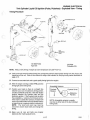
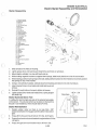
ENGINE ELECTRICAL
"
Ignition and Alternator Data
1985 ............... .. . . ......................................... . ... . . . 4.1
1986 ................................. . . .. ... .. . . . . .. . ..... . . . ...... . .. . 4.2
1987 ........... .. .. . ................................................. . . 4.3
1988 ............................................ . ......... . ........... . 4.4
1989 ................... . .... . .. . ...................................... . 4.5
1990 ........................... . ... .. .. . . ... .. . . . ... . . . ...... . ........ . 4.6
1991 ... . ........................ . .. . ......... . ............. .. ... . . . . .. . 4.7
"
,~
1992 .............. . ... . ... . . . ......................................... . 4.8
1993 ... . .................................... . ... . ... . ... . ... .. . ... .... . 4.9
1994 ..................................... . ................ . . . . .. .. . ... 4.10
1995 ............................. . ....... . .............. . . . . . .... . .. . . 4.11
Ignition Systems
Typical 1985 - Current Timing Advance Curves ............ . ......... . . . .... 4.12
Conversion Chart - Degrees to Piston Position B.T.D.C.
..
Timing
\
.....
Single Cylinder COl Ignition - Exploded View - Timing ....... .. .. .. ...... .. . .. 4.1 ~
Twin Cylinder Fan COl Ignition (Fixed) - Exploded View - Timing ......... . .... 4.15
Twin Cylinder Fan COl Ignition (Adjustable) - Exploded View - Timing ...... ... 4.16
Twin Cylinder Liquid COl Ignition (Pulse, Pulseless) - Exploded View - Timing .. 4.17
Three Cylinder COl Ignition (Pulse, Trigger) - Exploded View - Timing ......... 4.18
Three Cylinder COl Ignition (Storm and XLT) - Exploded View - Timing ....... . 4.19
Operating RPM Timing Check - All Models ............................... . . 4.20
a
sm4
Ignition System Troubleshooting
Ignition System Testing .................................................. 4.21
o
Ignition/Charging System Testing .... .... ...................... ....... 4.22-4.25
Alternator
Ignition System Troubleshooting . .. ..................... ............. ... . . 4.26
Alternator Output Test - Open Circuit . . . . . . . . . . . . . . . . . . . . . . . . . . . . . . . . . . . . .. 4.27
Typical Exciter, Pulser or Lighting Coil Replacement ......... .... ..... . ..... 4.28
Battery Service .. ... . .... . ...... ...... ..................... ............ 4.29-4.30
Electric Starter System
Elec'tric Starter System Testing . ..... .... .. . .............. ... ........... . . 4.31
Electric Starter System Testing (Static) ........................... .. ....... 4.32
Electric Starter Reassembly and Reinstallation ............................. 4.33
Electronic Fuel Injection
EFI Introduction and Operation ...... . .. .................. . ....... . . .. . .. . 4.35
EFI Data .............................................................. 4.36
Battery Maintenance and Testing ..... . ..... .. . . ...... ..... ...... ........ . 4.37
Power Up Testing ......................................... . ...... . . 4.38-4.41
Alternator Controlled Switch "ACS" ....... . .. . . ....... ........ ..... . . ..... 4.42
Basic Operation - System II ... . . . . . . . . . . . . . . . . . . . . . . . . . . . . . . . . . . . . . . . . . .. 4.43
Fuel Handling System
Tank, Hose and Filters ................... .... . ............ . ............. 4.44
Fuel Pump . ...... .. .. . ......... . .. ... .. . .. . ............. ... ... .... .... 4.44
Fuel Rail .............................................................. 4.45
Return Hose ..... . ..... . ..... . .. .... ........... . .. ................... .. 4.45
Pressure Regulator . . . . . . . . . . . . . . . . . . . . . . . . . . . . . . . . . . . . . . . . . . . . . . . . . . . .. 4.45
Injector
(M~chanical)
. .. ....................... .. ........................ 4.46
EFI Fuel System Maintenance and Testing ...... . .. ... . .... .... ............ 4.47
Throttle Body ... . ................ .. ..................... . .............. 4.48
8/94
b
i
[!J
Electronic Control System
System III - Electronics Operation ............... . .............. ..... . 4.49-4.50
System 111- Electronics Testing ......... .... . ......................... 4.51-4.56
Select Monitor/RPM Sensor .......... .................. ............. . ... 4.54
Throttle Position Sensor . . . . . . . . . . . . . . . . . . . . . . . . . . . . . . . . . . . . . . . . . . . . . . . .. 4.55
Intake Air Temperature Sensor ........................................... 4.56
Crankcase Temperature Sensor .. . . . . . . . . . . . . . . . . . . . . . . . . . . . . . . . . . . . . . . .. 4.56
Barometric Pressure Sensor . . . . . . . . . . . . . . . . . . . . . . . . . . . . . . . . . . . . . . . . . . . .. 4.57
MR Adjustments ........... .. ........ . . ................................ 4.58
Type II System - 1991 to Current EFI's .......... . ... ................... ... 4.59
Fuel Injectors . . . .... .. ............................... . . . ............... 4.60
Dropping Resistor ...... .. ......... . ... . . ... .... .... ..... ............... 4.60
ECU Diagnostics ... ........... ....... ................ . ............... .. 4.61
Select Monitor Readings ................................................ 4.61
Mode Description Chart ............ ..... ................................ 4.61
Memory Fail Code Description ........... .. . . .... . .. .. . .. ................ 4.61
EFI Electronics . . . . . . . . . . . . . . . . . . . . . . . . . . . . . . . . . . . . . . . . . . . . . . . . . . . . . . . . . 4.62
1994-1995 Wiring Diagram, RXL ....................... . .... ... .......... 4.63
1994-1995 Wiring Diagram, 500 EFI ........ .... . .. ... . .... ...... .. ... 4.64-4.65
c
Si94
-
.~
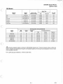
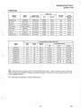
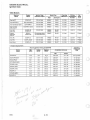
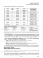
ENGINE ELECTRICAL
Ignition Data
1985 Models
Spark Plug
Engine
Model
Ignition Type
Alternator Output
NGK
Champion
Plug Gap
Inches
Star
EC25PS-06
CDI-100 Watt
BR8ES
RN-3C
.020
SS
EC44-2PM-3100
CDI-120 Watt
BR9ES
RN-2C
.020
Indy Trail
EC44-2PM-2100
CDI-120 Watt
BR9ES
RN-2C
.020
Indy 400
EC40PL-02
CDI-120 Watt
BR9ES
RN-2C
.020
Indy 600
EC60PL-02
CDI-120 Watt
BR9ES
RN-2C
.020
EC44-2PM-5000
CDI-120 Watt
BR9ES
RN-2C
.020
Machine
Model
Long Track
Running Ignition Timing at 3000 RPM
Engine
Model
MM
BTDC
Inches
BTDC
Acceptable Variances
De¥rees
B DC
MM
Inches
Degrees
EC25PS-06
4.19
.165
27.5
3.35-5.12
.132-.202
24.5-30.5
EC44-2PM-3100
3.93
.1 55
26.5
3.39-4.56
.133-.179
24.5-28.5
EC44-2PM-2100
3.93
.155
26.5
3.39-4.56
.133-.179
24.5-28.5
EC40PL-02
5.19
.204
30.5
4.55-5.85
.179-.230
28.5-32.5
EC60PL-02
4.10
.162
27.0
3.81-4.40
.150-.173
26-28
EC44-2PM-5000
3.93
.155
26.5
3.36-4.56
.1 33-.179
24.5-28.5
A
All above engines require a minimum of 88 (R+M)/2 octane fuel. If fuels of a lesser octane number are
used or engines are subjected to frequent overheated situations, the timing must be adjusted to the low side
of the accepted variance.
R.F.I. spark plug cap resistance: 3,700 to 6,300 ohms.
4.1
8/94
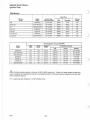
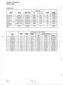
ENGINE ELECTRICAL
Ignition Data
1986 Models
Spark Plug
Engine
Model
Ignition Type
Alternator Output
NGK
Champion
Plug Gap
Inches
EC25PS-06
CDI-100 Watt
SR8ES
RN-3C
.020
Sprint (ES)
EC34-2 PM-O 1102
CDI-120 Watt
SR9ES
RN-2C
.020
SS
Machine
Model
Star
EC44-2PM-3100
CDI-120 Watt
SR9ES
RN-2C
.020
Indy Trail
EC50PM-01
CDI-120 Watt
SR9ES
RN-2C
.020
Indy 400
EC40PL-02
CDI-120 Watt
SR9ES
RN-2C
.020
Indy 600 (LE)
EC60PL-02
CDI-120 Watt
SR9ES
RN-2C
.020
EC44-2PM-5100
CDI-120 Watt
SR9ES
RN-2C
.020
Long Track
Running Ignition Timing at 3000 RPM
Engine
Model
MM
BTDC
Inches
BTDC
De¥rees
B DC
EC25PS-06
4.19
.165
27.5±3
EC34-2PM-01/02
3.41
.134
25.5±2
EC44-2PM-3100
3.93
.155
26.5±2
EC50PM-01
3.26
.128
24.0±2
2.75-3.53
EC40PL-02
5.19
.204
30.5±2
4.55-5.85
.179-.230
15°@ 7500
EC60PL-02
4.10
.162
27.0±1
3.81-4.40
.150-.173
20° @7500
EC44-2PM-5100
3.40
.134
24.5±2
2.87-3.93
.113-.155
12.5°@6500
Acceptable Variances
MM
Inches
Degrees
3.35-5.12
.1 32-.202
20.5°@6000
2.90-3.94
.114-.160
15.5°@7000
3.39-4.56
.133-.179
14.5°@6500
.108-.150
16°@ 6500
A
All above engines require a minimum of 88 (R+M)/2 octane fuel. If fuels of a lesser octane number are
used or engines are subjected to frequent overheated situations, the timing must be adjusted to the low side
of the accepted variance.
R.F.1. spark plug cap resistance: 3,700 to 6,300 ohms.
8/94
4.2
J
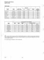
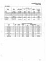
ENGINE ELECTRICAL
Ignition Data
1987 Models
Spark Plug
Machine
Model
Engine
Model
Ignition Type
Alternator Output
NGK
Champion
Plug Gap
Inches
EC25PS-06
COI-l00 Watt
BR8ES
RN-3C
.025
Sprint (ES)
EC34-2PM-Ol /02
COI-120 Watt
BR9ES
RN-2C
.025
Indy Sport
EC34-2PM-03
COI-120 Watt
BR9ES
RN-2C
.025
Indy Trail (All)
EC50PM-Ol/02
COI-120 Watt
BR9ES
RN-2C
.025
Indy 400
EC40PL-02
COI-120 Watt
BR9ES
RN-2C
.025
Indy 600
EC60PL-02
COI-120 Watt
BR9ES
RN-2C
.025
EC44-2PM-5100
COI-120 Watt
BR9ES
RN-2C
.025
Star, Star Trak
Long Track (RLR)
Running Ignition Timing at 3000 RPM
Engine
Model
MM
BTDC
Inches
BTDC
Acceptable Variances
De¥rees
B DC
MM
Inches
Degrees
EC25PS-06
4.19
.165
27.5±3
3.35-5.12
.1 32-.202
20.5° @6000
EC34-2PM-Ol /02
3.41
.1 34
25.5± 2
2.90-3.94
.1 14-.160
15.5° @7000
EC34-2PM-03
3.41
.134
25.5±2
2.90-3.94
.114-. 160
15.5°@7000
EC50PM-Ol/02
3.26
.128
24.0±2
2.75-3.53
.108-.150
16°@6500
EC40PL-02
5.1 9
.204
30.5±2
4.55-5.85
.179-.230
15° @ 7500
EC60PL-02
4.10
.1 62
27.0±1
3.81 -4.40
.150-.173
200@7500
EC44-2PM-5100
3.40
.134
24.5±2
2.87-3.93
.113-.1 55
12.5° @6500
A
All above engines require a minimum of 88 (R+M)/2 octane fuel. If fuels of a lesser octane number are
used or engines are subjected to frequent overheated situations, the timing must be adjusted to the low side '
of the accepted variance.
R.F.I. spark plug cap resistance: 3,700 to 6,300 ohms.
4.3
8/94
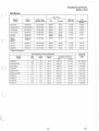
ENGINE ELECTRICAL
Ignition Data
1988 Models
Spark Plug
Machine
Model
Star, Star Trak
Sprint (ES)
Engine
Model
Ignition Type
Alternator Output
NGK
Champion
Plug Gap
Inches
COl Box
Identification
Number
EC25PS-06
CDI-100 Watt
BR8ES
RN-3C
.025
CU6204
EC34-2PM-Q2
CDI-120 Watt
BR9ES
RN-2C
.025
CU6409
Indy Sport
EC34-2PM-Q3
CDI-120 Watt
BR9ES
RN-2C
.025
CU6409
Indy Trail (All)
EC50PM-Q1/02
CDI-120Watt
BR9ES
RN-2C
.025
CU6410
Indy 400 (All)
EC40PL-Q2/03
CDI-120 Watt
BR9ES
RN-2C
.025
CU6408
EC65PL-01
CDI- 120 Watt
BR9ES
RN-2C
.025
CU1559
EC44-2PM-4100
CDI-120Watt
BR9ES
RN-2C
.025
CU6405
Indy 650
Long Trak (RLR)
Running Ignition Timing at 3000 RPM
Engine
Model
MM
BTDC
Inches
BTDC
De¥rees
B DC
Acceptable Variances
MM
Inches
Degrees
20.5°@6000
EC25PS-06
4.19
.165
27.5±3
3.35-5.12
.132-.202
EC34-2PM-Q2
3.41
.134
25.5±2
2.90-3.94
.114-.160
15.5°@7000
EC34-2PM-Q3
3.41
.134
25.5±2
2.90-3.94
.114-.160
15S@7000
EC50PM-01/02
3.26
.128
24.0±2
2.75-3.53
.108-.150
16° @ 6500
EC40PL-Q2I03
5.19
.204
30.5±2
4.55-5.85
.179-.230
15° @ 7500
EC65PL-Q1
4.10
.162
27.0±1
3.81-4.40
.150-.173
200@ 7500
EC44-2PM-4100
3.76
.148
26.5±2
3.23-4.29
.1 27-.169
14.5°@6500
A
All above engines require a minimum of 88 (R+M)/2 octane fuel. If fuels of a lesser octane number are
used or engines are subjected to frequent overheated situations, the timing must be adjusted to the low side
of the accepted variance.
R.F.I. spark plug cap resistance: 3,700 to 6,300 ohms.
8/94
4.4
ENGINE ELECTRICAL
Ignition Data
1989 Models
Spark Plug
Engine
Model
Ignition Type
Alternator Output
NGK
Champion
Plug Gap
Inches
COl Box
Identification
Number
EC25PS-06
CDI-100Watt
BR8ES
RN-3C
.025
CU6204
Sprint (ES)
EC34-2PM-02
CDI-120 Watt
BR9ES
RN-2C
.025
CU6409
Indy Sport
EC34-2PM-03
CDI-120Watt
BR9ES
RN-2C
.025
CU6409
Indy Trail (All)
EC50PM-01/02J03
CDI-120 Watt
BR9ES
RN-2C
.025
CU6410
Indy 400 (All)
EC40PL-02
CDI-120 Watt
BR9ES
RN-2C
.025
CU6408
Indy 500 (All)
ECSOPL-01/02
CDI-120 Watt
BR9ES
RN-2C
.025
CU6408
EC65PL-01
CDI-120 Watt
BR9ES
RN-2C
.025
CU1559
EC44-2PM-4100
CDI-120 Watt
BR9ES
RN-2C
.025
CU6405
Machine
Model
Star, Star Trak
Indy 650
Long Trak (RLR)
Running Ignition Timing at 3000 RPM
Engine
Model
MM
BTDC
Inches
BTDC
De~rees
B DC
MM
Inches
Degrees
EC25PS-06
4.19
.165
27.5±3
3.35-5.12
.132-.202
20.5°@6000
EC34-2PM-02
3.41
.134
25.5±2
2.90-3.94
.114-.160
15.5° @7000
EC34-2PM-03
3.41
.134
25.5±2
2.90-3.94
.11 4-.1 60
15.5°@7000
EC50PM-01/02
3.26
.128
24.0±2
2.75-3.53
.108-.150
16°@6500
EC50PM-03
5.03
.198
30.0±2
4.40-5.69
.1 73-.224
22°@6500
EC40PL-02
5.19
.204
30.5±2
4.55-5.85
.179-.230
15°@ 7500
EC50PL-01/02
5.19
.204
30.5±2
4.55-5.85
.179-.230
15°@7500
EC65PL-01
4.10
.162
27.0±1
3.81-4.40
.150-.1 73
200@7500
EC44-2PM-4100
3.76
.148
26.5±2
3.23-4.29
.127-.169
14.5°@6500
Acceptable Variances
A
All above engines require a minimum of 88 (R+M)/2 octane fuel. If fuels of a lesser octane number are
used or engines are subjected to frequent overheated situations, the timing must be adjusted to the low side
of the accepted variance.
R.F.1. spark plug cap resistance: 3,700 to 6,300 ohms.
4.5
8/94
ENGINE ELECTRICAL
Ignition Data
1990 Models
Spark Plug
Machine
Model
Engine
Model
Ignition Type
Alternator Output
NGK
Champion
Plug Gap
Inches
CDI Box
Identification
Number
EC25PS-06
CDI-150 Watt
BR8ES
RN-3C
.025
CU2167
Sprint (ES)
EC34-2PM-02
CDI-150 Watt
BR9ES
RN-2C
.025
CU6409
Indy Sport
EC34-2PM-03
CDI-1 50 Watt
BR9ES
RN-2C
.025
CU6409
EC50PM-01/02 /03
CDI-200 Watt
BR9ES
RN-2C
.025
CU6413
EC40PL-02
CDI-200 Watt
BR8ES
RN-3C
.025
CU6412
EC50PL-01/02/03
CDI-200 Watt
BR8ES
RN-3C
.025
CU6412
EC65PL-01
-03
CDI-120 Watt
-180 Watt
BR9ES
RN-2C
.025
CU1559
CU2178
Star, Star Trak
Indy Trail (All)
Indy 400
Indy 500 (All)
Inc!. WideTrak
Indy 650
RXL
Running Ignition Timing at 3000 RPM
Engine
Model
MM
BTDC
Inches
BTDC
De¥rees
B DC
EC25PS-06
4.19
.165
27.5±3
Acceptable Variances
MM
Inches
Degrees
3.35-5. 12
.132-.202
20.5° @6000
EC34-2PM-02
3.41
.134
25.5 ± 2
2.90-3.94
.114-.160
15.5° @7000
EC34-2PM-03
3.4 1
.134
25.5±2
2.90-3.94
.114-.1 60
15.5°@7000
EC50PM-01/02
3.26
.128
24.0±2
2.75-3.53
.108-. 150
160 @ 6500
21 ° @ 6500
EC50PM-03
4.71
.185
29.0±2
4.10-5.35
.162-.210
EC40PL-02
5.36
.210
31.0±2
4.71-6.04
.185-.238
15°@ 7500
EC50PL-01/02
5.36
.210
31 .0±2
4.71-6.04
.1 85-.238
15°@ 7500
EC50PL-03
5.36
.210
31 .0±2
4.71-6.04
.185-.238
15.5° @7000
EC65PL-01
4.10
.1 62
27.0±1
3.81-4.40
.150-.173
20 0 @7500
EC65PL-03
5.02
.198
30.0±1
1.65-2.06
.065-.081
18° @7500
8/94
4.6
f'
ENGINE ELECTRICAL
Ignition Data
c
1991 Models
Spark Plug
Champion
PIUr. Gap
MMI nches
CDI Box
Identification
Number
BR8ES
RN-3C
0.7/028
CU6204
BR8ES
RN-2C
0.7/028
CU6409
CDI-200 Watt
BR8ES
RN-2C
0.7/028
CU6416
EC50PM-Ol/02l03
CDI-200 Watt
BR8ES
RN-2C
0.7/028
CU6413
EC40PL-02
EC40PL-04
CDI-200 Watt
BR8ES
RN-3C
0.7/028
CU6412
CU6415
Indy 500 (All)
Incl. WideTrak
EC50PL-Ol/02l03
EC50PL-04/05/06
CDI-200 Watt
BR8ES
RN-3C
0.7/028
CU6412
CU6415
Indy 650/RXL
EC65PL-02/03
CDI-180 Watt
BR9ES
RN-2C
0.7/028
CU21 78
Engine
Model
Ignition Type
Alternator Output
NGK
StarLite
EC25PS-07
CDI-150 Watt
Indy Lite
EC34-2PM-03
CDI-150 Watt
Indy SportlGT
EC44-3PM-Ol
Indy Trail (All)
Machine
Model
Indy 400
Running Ignition Timing at 3000 RPM
Engine
Model
MM
BTDC
Inches
BTDC
De~rees
MM
Inches
Degrees
EC25PS-07
4.1 9
.1 65
27.5±3
3.35-5.12
.1 32-.202
20.5° @6000
EC34-2PM-03
3.41
.1 34
25.5±2
2.90-3.94
.114-.155
16° @7000
EC44-3PM-Ol
3.26
.128
24.0±2
2.75-3.811
.108-.1 50
16°@ 6500
EC50PM-Ol/02
3.26
.128
24.0±2
2.75-3.811
.108-.150
16° @ 6500
EC50PM-03
4.71
.185
29.0±2
4.10-5.35
.162-.210
21 ° @6500
EC40PL-02
_-04
5.36
3.93
.210
.155
31.0 ± 2
26.5±2
4.71-6.04
3.40-4.55
.185-.238
.133-. 179
16° @ 7500
EC50PL-Ol/02
-04/05
5.36
3.96
.210
.155
31.0±2
26.5±2
4.71-6.04
3.40-4.55
.185-.238
.133-.179
16°@7500
EC50PL-06
3.96
.155
26.5±2
3.40-4.55
.133-.179
16° @ 7500
EC65PL-02l03
3.26
.128
24.0±1
3.00-3.53
.118-.139
18° @7500
Acceptable Variances
B DC
c
4.7
8/94
ENGINE ELECTRICAL
Ignition Data
1992 Models
Spark Plug
Machine
Model
Engine
Model
Ignition Type
Alternator Output
NGK
Champion
Plug Gap
MMllnches
COl Box
Identification
Number
EC25PS-07
CDI-150 Watt
BR8ES'
RN-3C
0.7/028
CU6204
EC34-2PM-02/03/04
CDI-150 Watt
BR8ES'
RN-3C
0.7/028
CU6409
Indy Sport'GT
EC44-3PM-Ol
CDI-200 Watt
BR8ES'
RN-3C
0.7/028
CU6416
Indy Trail (All)
EC50PM-O 1/02/03
CDI-200Watt
BR8ES'
RN-3C
0.7/028
CU6413
EC45PL-02
EC45PL-Ol
CDI-200 Watt
BR8ES
BR9ES
RN-3C'
RN-2C'
0.7/028
CU6415
Indy 500, Classic
WideTrak,500SP
EC50PL-04/05/
06/07
CDI-200Watt
BR8ES
RN-3C'
0.7/028
CU6415
Indy 650, RXL
EC65PL-02/03
CDI-180 Watt
BR9ES
RN-2C'
0.7/028
CU2178
"8tarLite
Indy Lite/GT/DLX
Indy 440
IndyXCR
* Original Equipment
Running Ignition Timing at 3000 RPM
Engine
Model
MM
BTDC
Inches
BTDC
De¥rees
B DC
EC25PS-07
4.05
.159
27±3
EC34-2PM-02/03/04
3.28
.129
25±1.5
EC44-3PM-Ol
3.81
.150
26±1.5
EC50PM-Ol/02
3.81
.150
26±1.5
3.39-4.25
.133-.167
16° @6500
EC50PM-03
4.71
.185
29±1.5
4.25-5.20
.167-.204
19° @6500
EC45PL-02/01
4.40
.173
28±1 .5
3.91 -4.87
.156-.191
16°@7500
EC50PL-04/05/06
4.40
.173
28±1 .5
3.91-4.87
.156-.191
16°@7500
EC50PL-07
4.71
.185
29±1.5
4.25-5.20
.167-.204
17°@7500
EC65PL-02
-03
3.26
3.53
.128
.139
24±1.5
25±1.5
2.87-3.67
3.13-4.01
.113-.144
.123-.156
18° ~ 7500
19°
7500
4_8
8/94
h
Acceptable Variances
MM
Inches
Degrees
3.22-4.96
.127-.195
20.5°@6000
2.90-3.67
.114-.144
16°@7000
3.39-4.25
.133-. 167
16° @6500
ENGINE ELECTRICAL
Ignition Data
1993 Models
Spark Plug
Machine
Model
StarLite/GT
Ignition Type
Alternator Output
NGK
Champion
PIUPr Gap
MMI nches
CDI
Boxldentification
Number
EC25PS-07
CDI-150 Watt
BR8ES·
RN-3C
0.71.028
CU6204
RN-3C
0.7/.028
CU6409
RN~3C
0.71.028
CU6416
EC34-2PM-D2I04
CDI-150 Watt
BR8ES·
Indy SporVGT
EC44-3PM-Ol
CDI-200 Watt
BR8ES·
Indy Trail (All)
EC50PM-Dl
CDI-200 Watt
BR8ES·
RN-3C
0.7/.028
CU6413
0.7/.028
CU6415
IndyLitelGT/DLX
*
Engine
Model
Indy 440
Indy XCR
EC45PL-02
EC45PL-Dl
CDI-200 Watt
BR8ES
BR9ES
RN-3C·
RN-2C·
Classic
WideTrak
SOO EFI
EC50PL-D4
CDI-200 Watt
BR8ES
RN-3C·
0.71.028
CU6415
XLT(AII)
EC58PL-Dl
CDI11 70 Watt
BR9ES
RN-2C·
0.71.028
CU2194
Indy RXL
EC65PL-OS
CDI-180 Watt
BR9ES
RN-2C·
0.7/.028
CU2178
Indy Storm
EC75PL-Dl
CDI-170 Watt
BR9ES·
RN-2C
0.71.028
CU2196
OS/06/07
Original Equipment
Running Ignition Timing at 3000 RPM
Engine
Model
MM
BTDC
Inches
BTDC
EC25PS-07
4.0S
.159
EC34-2PM-02I04
3.28
.129
De¥rees
B DC
Operating
Acceptable Variances
Timing and
RPM
MM
Inches
27±3
3.22-4.96
.127-.195
20.5° @6000
25±1.5
2.90-3.67
.114-.144
16° @7000
EC44-3PM-Ol
3.81
.1SO
26±1.5
3.39-4.25
.133-.167
16° @6500
EC50PM-Dl
3.81
.1SO
26±1.5
3.39-4.25
.133-.1 67
16° @6500
EC45PL-Ol/02
4.40
.173
28±1.5
3.91-4.87
.156-.191
16° @7500
ECSOPL-D4/0S/06
4.40
.173
28±1.5
3.91-4.87
.lS6-.191
16° @7500
ECSOPL-07
4.71
.185
29±1.5
4.25-5.20
.167-.204
17"@7500
ECS8PL-Dl
4.40
.173
28±1 .5
3.91-4.87
.156-.191
20° @7500
EC6SPL-D5
3.S3
.1 39
25±1.5
3.13-4.01
.1 23-.1 S6
19° @7500
EC75PL-Ol
4.74
.187
28±1.5
4.30-5.28
.168-.206
12° @8000
4.9
8/94
ENGINE ELECTRICAL
Ignition Data
1994 Models
Mach ine
Mo del
Engine
Model
StarLiteJGT
IndyLite/GT/DLX
Ig nition Type
A lternator Output
Spark Plug
NGK
Champion
PI U
p, Gap
MMI nches
COl Box
Identification
Number
Flywheel
10#
EC25PS-07
CDI-150Watt
BR8ES·
RN-3C
0.7/.028
CU6204
FP5355
EC34-2PM-02I04
CDI-150Watt
BR8ES·
RN-3C
0.7/.028
CU6409
FP5439
EC44-3PM-Ol
CDI-200Watt
BR8ES·
RN-3C
0.7/.028
CU6416
FP5446
EC50PM-Ol/02l03
CDI-200Watt
BR8ES·
RN-3C
0.7/.028
CU6413
FP5441
Indy 440
Indy XCR
EC45PL-02
EC45PL-Ol
CDI-200Watt
BR8ES
BR9ES
RN-3C·
RN-2C·
0.7/.028
CU6415
FP5445
Classic
WideTrak
500 EFI
EC50PL05/06/07/08
CDI-200 Watt 05/06
CDI 250 Watt 07/08
BR8ES
RN-3C·
0.7/.028
CU6415
FP5445
XLT(AII)
EC58PL-Ol
CDI-170 Watt
BR8ES
RN-3C·
0.7/.028
CU2194
FP8312
Indy RXL
EC65PL-05/06
CDI-180 Watt
BR9 ES
RN-2C·
0.7/.028
CU2178
FP6392
EC80PL-Ol
CDI-170 Watt
BR9ES
RN-2C·
0.7/.028
CU2196
FP6369
Indy Sport/Super Sport
Indy Trail (All)
WideTrak GT
Indy Storm
* Original Equipment
Running Ig nitio n Timing at 3000 RPM
Engine
Model
MM
BT OC
Inches
BTOC
oe¥rees
B DC
Acceptable Variances
Operating
Tim ing and
RPM
MM
Inc hes
3.22-4.96
.127-.1 95
20S @6000
EC25PS-07
4.05
.1 59
EC34-2PM-02/04
3.28
.129
25±1.5
2.90-3.67
.114-. 144
16° @7000
EC44-3PM-Ol
3.81
.1 50
26±1.5
3.39-4.25
.133-.167
16° @6500
EC50PM-Ol/02l03
3.81
.150
26±1 .5
3.39-4.25
.133-.167
16° @ 6500
EC45PL-Ol/02
4.40
.173
28±1 .5
3.91-4.87
.156-.191
16° @ 7500
EC50PL-05/06
4.40
.173
28±1.5
3.91 -4.87
.156-.191
16° @ 7500
EC50PL-07/08
4.71
.185
29±1.5
4.25-5.20
.167-.204
lr@7500
EC58PL-Ol
4.40
.173
28±1.5
3.91-4.87
.156-.191
20° @7500
EC65PL-05/06
3.53
.139
25±1.5
3.13-4.01
.123-.1 56
19° @7500
EC80PL-Ol
2.96
.116
22±1.5
2.58-3.10
.102-.133
11 ° @8000
8/94
-
27±3
4.10
,)
ENGINE ELECTRICAL
Ignition Data
1995 Models
Machine
Model
StarLite
IndyLite Models
Engine
Model
Spark Plug
Alternator
Wattage
NGK
Champion
Plue Gap
MMI nches
COl Box
Identification
Number
Flywheel
10#
EC25PS07
150
BR8ES
RN-3C
0.71.028
CU6204
FP5355
EC34-2PM02lE02
150
BR8ES
RN-3C
0.71.028
CU6409
FP5439
FP5446
EC44-3PM01/02
200
BR8ES
RN-3C
0.7/.028
CU6416
EC50PM04/E04
200
BR8ES
RN-3C
0.71.028
CU6413
FP5441
EC50PM03
200
BR8ES
RN-3C
0.7/.028
CU6413
FP5441
Indy 440 LC/SKS
EC45PL02
200
BR8ES
RN-3C
0.7/.028
CU6415
FP5445
Indy XCR
EC45PL03
200
BR9ES
RN-2C
0.7/.028
CU6415
FP5445
EC50PL04/E04
200
BR8ES
RN-3C
0.7/.028
CU6415
FP5445
Indy Sport Models
• Indy Trai~Models
WideTrakGT
Indy 500/Classic
WideTrak LX
EC50PL06
200
BR8ES
RN-3C
0.7/.028
CU6415
FP5445
500 EFI
EC50PL07
250
BR8ES
RN-3C
0.7/.028
CU6415
FP5508
XLT/XLT SP/XLT SKS
EC58PL03
170
BR8ES
RN-3C
0.7/.028
CU2194
FP8312
Indy XCR 600
XLT Touring
Indy RXL/Touring
Indy Storm
EC5802
170
BR9ES
RN-2C
0.7/.028
CU2194
FP8312
EC58PLE04
170
BR8ES
RN-3C
0.7/.028
CU2194
FP8312
EC65PL05/E05
180
BR9ES
RN-2C
0.7/.028
CU2178
FP6392
EC80PL01
180
BR8ES
RN-3C
0.7/.028
CU2508
FP6398
Running Ignition Timing at 3000 RPM
Engine
Model
MM
BTOC
EC25PS07
4.05
EC342PM02lE02
3.67
EC443PMO 1/02
3.81
EC50PM04/E04
EC50PM03
,3.81
Inches
BTOC
r _
.
~
Acceptable Variances
oe¥rees
B OC
MM
Inches
operatin¥>
Timing °BT C
RPM
.1 59
27±3
3.22-4.96
.127-. 195
20.5° @6000
.145
26.5±1.5
3.28-4.08
.129-.161
15.5° @ 7000
.150
26±1.5
3.39-4.25
.133-.167
16° @6500
.150
26±1 .5
3.39-4.25
.133-.167
16° @ 6500
4.71
.185
29±1.5
4.25-5.20
.1 67-.204
19° @ 7500
16° @7500
EC45PL02l03
4.40
.173
28±1.5
3.91-4.87
.156-.191
EC50PL04/E04/06
4.40
.173
28±1 ,5
3.91-4.87
.156-.191
16° @ 7500
EC50PL07
4.71
.1 85
' . 29±1.5
4.25-5.20
.1 67-.204
1]o @7500
EC58PL02l03/E04
4.40
.173
28±1.5
3.91-4.87
.156-. 191
20 0 @7500 -
EC65PL05/E05
3.53
.139
25±1 .5
3.13-4.01
.123-.156
19° @ 7500
EC80PL01
2.96
.11 6
22±1 .5
2.58-3. 10
.102-.1 33
W @8000
4.1 1
,
8/94
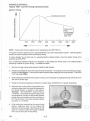
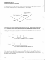
ENGINE ELECTRICAL
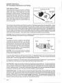
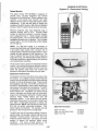
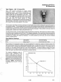
Typical 1985 - Current Timing Advance Curves
Ignition Timing
MAXIMUM ADVANCE
OPERATING
RPM
(DEPENDING
ON ENGINE)
SEE DATA
1000
2000
3000
4000
5000
6000
7000
8000
RPM
NOTE: Always verify timing of engine at room temperature only (68 0 F/20° C).
The ignition maximum advance is at or near 3000 RPM on all current style ignition systems. Verify the ignition
position at maximum advance when checking the timing.
If engine damage has occurred due to a suspected ignition related problem, check the ignition timing at the
specified operating RPM.
Due to differences between engines, it is necessary to dial indicate the timing marks on all engines before
attempting to adjust the ignition timing. To indicate the marks:
.
I'
cy~nder
1.
Remove the mag
2.
Rotate the cranRsbaft by hand while observing the dial indicator. As the piston touches the indicator plunger,
the dial will begi~tO'rotate. Find the pOint where the pointer stops rotating and reverses direction. This will be
TDC (Top Dead Ceri'mJ").
3.
While holding the crankshaft with the pi~ton at TDC, zero the indicator by rotating the bezel until the 0 on the
dial and the pointer align.
4.
Rotate the crankshaft opposite the direction of rotation about .250 BTDC (2 1/2 pOinter revolutions).
5.
Determine the correct ignition timing position from
the ignition data charts and rotate the crankshaft in
the normal direction of rotation to that position.
(Example: 1993 EC50PM-01 engine timing is
.150 BTDC. The crankshaft must be rotated in the
normal direction of rotation so that the dial indicator
pointer does one complete revolution and stops on
50. This should be 1 1/2 pointer revolutions before
top center, or .150 BTDC.
6.
While holding the crankshaft at the correct timing
position, determine which of the rotating and
stationary timing lines align. Mark these lines with
chalk or a marker to make them easier to identify
when you are doing the running timing.
8/94
spark plug and install the dial indicator.
4.12
'-, .
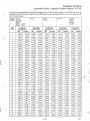
ENGINE ELECTRICAL
Conversion Chart - Degrees to Piston Position - B.T.D.C.
(
If the ignition timing specification is listed in degrees only, convert to either inches or mm BlOC and use a dial
indicator to verify timing marks. NOTE: Due to differing rod lengths and engine strokes, consult the engine model
list for correct engine.
Engine
Model
DEG.
BTDC
EC40PL
EC44-2PM
EC44-3PM
EC45PL
EC50PL EC60PL
EC58PL EC65PL
11 2 MM ROD
60MM STROKE
MM
o
INCHES
EC35PL
130 MM ROD
70 MM STROKE
125MM ROD
65 MM STROKE
MM
MM
INCHES
EC25PF
EC25PS
EC44PT
EC44PQ
EC44 PM
EC34-2PM
EC75PL
EC80PL
INCHES
103 MM ROD
55.6 MM STROKE
MM
INCHES
120 MM ROD
60MM STROKE
MM
INCHES
1
0.0058
0.0002
0.0068
0.0003
0.0062
0.0002
0.0054
0.0002
0.0057
0.0002
2
0.0232
0.0009
0.0271
0.0011
0.0249
0.0010
0.0215
0.0008
0.0228
0.0009
3
0.0521
0.0021
0.0609
0.0024
0.0561
0.0022
0.0484
0.0019
0.0514
0.0020
4
0.0926
0.0036
0.1082
0.0043
0.0997
0.0039
0.0860
0.0034
0.0913
0.0036
5
0.1447
0.0057
0.1690
0.0067
0.1558
0.0061
0.1343
0.0053
0.1426
0.0056
6
0.2083
0.0082
0.2432
0.0096
0.2242
0.0088
0.1933
0.0076
0.2053
0.0081
7
0.2833
0.0112
0.3309
0.0130
0.3050
0.0120
0.2630
0.0104
0.2793
0.0110
8
0.3698
0.0146
0.4319
0.0170
0.3981
0.0157
0.3432
0.0135
0.3646
0.0144
9
0.4677
0.0184
0.5463
0.0215
0.5036
0.0198
0.4341
0.0171
0.4612
0.0182
10
0.5770
0.0227
0.6739
0.0265
0.6212
0.0245
0.5355
0.0211
0.5689
0.0224
11
0.6976
0.0275
0.8147
0.0321
0.7510
0.0296
0.6474
0.0255
0.6878
0.0271
12
0.8294
0.0327
0.9687
0.0381
0.8930
0.0352
0.7698
0.0303
0.8178
0.0322
13
0.9724
0.0383
1.1357
0.0447
1.0470
0.0412
0.9025
0.0355
0.9588
0.0377
14
1.1265
0.0444
1.3157
0.0518
1.2129
0.0478
1.0456
0.0412
1.1108
0.0437
15
1.2917
0.0509
1.5086
0.0594
1.3908
0.0548
1.1989
0.0472
1.2737
0.0501
16
1.4678
0.0578
1.7143
0.0675
1.5804
0.0622
1.3624
0.0536
1.4474
0.0570
17
1.6548
0.0652
1.9327
0.0761
1.7818
0.0701
1.5359
0.0605
1.6318
0.0642
18
1.8526
0.0729
2.1637
0.0852
1.9948
0.0785
1.7195
0.0677
1.8269
0.0719
19
2.0611
0.0811
2.4072
0.0948
2.2193
0.0874
1.9130
0.0753
2.0326
0.0800
20
2.2802
0.0898
2.6631
0.1048
2.4552
0.0967
2.1163
0.0833
2.2487
0.0885
21
2.5098
0.0988
2.9312
0.1154
2.7024
0.1064
2.3294
0.0917
2.4752
0.0974
22
2.7497
0.1083
3.2114
0.1264
2.9608
0.1166
2.5521
0.1005
2.7119
0.1068
23
3.0000
0.1181
3.5036
0.1379
3.2303
0.1272
2.7843
0.1096
2.9587
0.1165
24
3.2603
0.1284
3.8077
0.1499
3.5107
0.1382
3.0260
0.1191
3.2156
0.1266
25
3.5307
0.1390
4.1235
0.1623
3.8019
0.1497
3.2769
0.1290
3.4824
0.1371
26
3.8110
0.1 500
4.4508
0.1752
4.1038
0.1616
3.5370
0.1393
3.7590
0.1480
27
4.1010
0.1615
4.7895
0.1886
4.4161
0.1739
3.8062
0.1498
4.0452
0.1593
28
4.4007
0.1733
5.1395
0.2023
4.7389
0.1866
4.0843
0.1608
4.3410
0.1709
29
4.7098
0.1854
5.5005
0.2166
5.0719
0.1997
4.3712
0.1721
4.6461
0.1829
30
5.0282
0.1980
5.8724
0.231 2
5.4149
0.2132
4.6667
0.1837
4.9604
0.1953
31
5.3559
0.2109
6.2550
0.2463
5.7679
0.2271
4.9708
0.1957
5.2839
0.2080
32
5.6926
0.2241
6.6482
0.2617
6.1306
0.2414
5.2832
0.2080
5.6163
0.2211
33
6.038 1
0.2377
7.0517
0.2776
6.5028
0.2560
5.6039
0.2206
5.9575
0.2345
34
6.3924
0.2517
7.4654
0.2939
6.8845
0.2710
5.9326
0.2336
6.3073
0.2483
35
6.7552
0.2660
7.8891
0.3106
7.2754
0.2864
6.2693
0.2468
6.6656
0.2624
36
7.1 263
0.2806
8.3225
0.3277
7.6753
0.3022
6.6138
0.2604
7.0322
0.2769
37
7.5057
0.2955
8.7655
0.3451
8.0840
0.3183
6.9658
0.2742
7.4069
0.2916
38
7.8931
0.3108
9.2179
0.3629
8.5015
0.3347
7.3253
0.2884
7.7896
0.3067
39
8.2883
0.3263
9.6795
0.3811
8.9274
0.3515
7.6920
0.3028
8.1801
0.3221
40
8.6912
0.3422
10.1499
0.3996
9.3616
0.3686
8.0659
0.3176
8.5782
0.3377
4.13
8/94
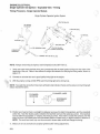
ENGINE ELECTRICAL
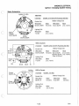
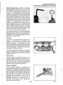
Single Cylinder COl Ignition - Exploded View - Timing
Timing Procedure - Single Cylinder Models
)
Single Cylinder Capacitor Ignition System
STATOR PLATE
RFI SPARK
PLUG CAP
LIGHTING CO IL
FLYWHEEL
o
CO l CONTROL
VIBRATION
OAMPNER
1
EXCITER COIL
UNIT~STATOR PLUGS
QUICK COUPLERS
1·/
.
~@.
~-
~~
TORQUE TO 8 TO 10 IN. LBS.
NOTE: Always verify timing of engine at room temperature only (68 0 F/20° C).
7.
Verify and mark which flywheel timing line corresponds with the listed ignition timing from the chart at the
beginning of this unit. Refer to the method of using a dial indicator for verifying the timing marks, shown on
page 4.12.
8.
Connect an accurate tach and a good quality timing light to the engine.
9.
With the engine running at 3000 RPM, point the timing light at the timing hole.
NOTE: Your sight line during the timing mark verification (dial indicator check) and the actual running timing light
check, must be the same.
FLYWHEEL
ROTATION
!
FLYWHEEL LINES
PX<__
~.
STATIONARY
POINTER
10. Position your head so there is a straight line between your eye, the static timing pointers, and the crankshaft
center line. Note the relative position between the flywheel mark and the stationary pOinter. If the flywheel
mark is within the acceptable +/- variance, the timing is correct. If the mark is outside the variance, then the
stator will have to be rotated either with crankshaft rotation to retard timing, or against rotation to advance it.
NOTE: The recoil and recoil cup must be removed to loosen stator bolts and change the timing.
11. Make sure all nuts and bolts are properly tightened after making adjustments.
8/94
4.14
10
,
ENGINE ELECTRICAL
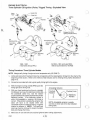
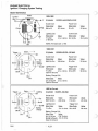
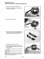
Twin Cylinder Fan COl Ignition (Fixed) - Exploded View - Timing
Timing Procedure
NON ADJUSTABLE SYSTEM
LI GHTING COIL
STAT IONARY
CO I LS
CO l PLUG
-
I
NOTE: Always verify timing of engine at room temperature only (68 0 F/20° C).
12. Verify and mark which flywheel timing line corresponds with the listed ignition timing from the chart at the
beginning of this unit. Refer to the method of using a dial indicator for verifying timing marks described on
page 4.12.
13. Connect an accurate tach and a good quality timing light to the engine.
c
NOTE: Acceptable variance
is usually one line on either
side of the dial indicated
blower housing stationary
line.
Blower Housing
Stationary
Lines
14. With the engine running at 3000 RPM, point the timing light at the blower housing stationary lines. If the
flywheel mark aligns with the correct stationary line or anywhere in the acceptable +/- variance, the timing is
correct. If the timing is not correct, follow steps 4 through 7, re-checking the timing after each step.
o
15. Disconnect the ignition kill cirQuit by disconnecting the black wire at the COl module.
16. Check the exciter coil resistance and replace if necessary.
17. Replace the COl module.
18. Replace the flywheel.
4.15
8/94
ENGINE ELECTRICA L
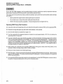
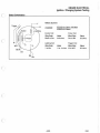
Twin Cylinder Fan COl Ignition (Adjustable) - Exploded View - Timing
Timing Procedure
~ RFICAP
00
FAN
120 Watt Pulse Type
150 and 200 Watt Pulseless
NOTE: Always verify timing of engine at room temperature only (68 0 F/20° C).
19. Verify and mark which blower housing timing line corresponds with the listed ignition timing from the charts at
the beginning of this unit. Refer to the method of using a dial indicator for verifying timing marks described on
page 4. 12.
20. Connect an accurate tach and a good quality timing light to the engine.
NOTE: Acceptable variance
is usually one line on either
side of the dial indicated
blower housing stationary
line.
Blower Housing
Stationary
Lines
21. With the engine running at 3000 RPM, point the timing light at the blower housing stationary lines. If the
flywheel mark aligns with the correct stationary line or anywhere in the acceptable +/- variance, the timing is
correct.
22. If the mark is outside the acceptable variance, the stator must be either rotated with crankshaft rotation to
retard the ti ming, or against rotation to advance it. NOTE: The recoi l and recoil cup must be removed to
loosen the stator bolts and change the timing.
23. Make sure all nuts and bolts are properly tightened after making adjustments.
8/94
4.16
ENGINE ELECTRICAL
Twin Cylinder Liquid COl Ignition (Pulse, Pulseless) - Exploded View - Timing
c
Timing Procedure
STATOR PLATE
EXCITER COIL
PULSER COIL
LIGHTING COIL
c
~ RFICAP
o~
120 Watt Pulse
Type COl
200 Watt
Pulseless COl
NOTE: Always verify timing of engine at room temperature only (68 0 F/20° C).
24. Verify and mark which flywheel timing line corresponds with the listed ignition timing from the chart at the
beginning of this unit. Refer to the method of using a dial indicator for verifying timing marks described on
page 4.12.
25. Connect an accurate tach and a good quality timing light to the engine.
c
26. With the engine running at 3000 RPM point the
timing light at the timing hole.
Acceptable Variance
27. Position your head so there is a straight line
between your eye, the stationary timing pointer,
and the crankshaft center line. Note the relative
position between the flywheel mark and the
stationary pointer. If the flywheel mark is within
the acceptable +/- variance, the timing is correct.
If the mark is outside the variance, the stator will
have to be rotated either with crankshaft rotation
to retard timing, or against rotation to advance it.
NOTE: The recoil and recoil cup must be
removed to loosen stator bolts and change the
timing.
Flywheel
Rotation
!
Flywheel Lines
Stationary
Pointers
NOTE: Acceptable variance is usually
one line on either side of the dial indicated
timing mark.
28. Make sure all nuts and bolts are properly
tightened after making adjustments.
4.17
8/94
ENGINE ELECTRICAL
Three Cylinder COl Ignition (Pulse, Trigger) Timing - Exploded View
Stator
Plate
Exciter Coil
Lighting
Coil
Lighting Coil
Flywheel
Charging Coil (RXL)
Lighting Coil (650, Storm)
1985 - 1990
3 Cylinders (Except RXL)
All RXL's, 1991 and Later 650's,
1993 to Current Storms 180 Watt
Timing Procedure: Three Cylinder Models
NOTE: Always verify timing of engine at room temperature only (20°C/68°F).
1. Verify and mark which flywheel timing line corresponds with the listed ignition timing from the chart at the
beginning of this section. Refer to the method of dial indicator use for verifying timing marks described on
page 4.12.
2.
Connect an accurate tach and a good quality timing light to the engine.
3.
With the engine running at 3000 RPM , point the
timing light at the timing hole.
4.
With your head positioned so there is a straight
line between your eye, the stationary pointer and
the crankshaft center line, note the relative
position between the marked flywheel line and the
stationary pOinter. If the stationary pOinter is
within the acceptable ± variance, the timing is
correct. If the pOinter is outside the variance, the
stator will have to be rotated either with
crankshaft rotation to retard the timing, or against
rotation to advance it. NOTE: The recoil and
recoil cup must be removed to loosen the stator
bolts and change the timing.
'
5.
Acceptable Variance
Flywheel
Rotation
!
Stationary
Pointers
NOTE: Acceptable variance is usually
one line on either side of the dial indicated
timing mark.
Make sure all nuts and bolts are properly tightened after making adjustments.
8/94
Flywheel Lines
4.18
)
ENGINE ELECTRICAL
Three Cylinder CDl lgnition (Storm/XLT) Timing - Exploded View
Pulser Coil
l::I--~--
Stator Plate
*Lighting/Exciter
~---
Flywheel
COl Control Box
\-------r-,."----
RFI Spark Plug Cap
Secondary
Cable
170 Watt
1993 to current XLT
Secondary
Coils
* The Exciter Coil can be identified by
wire color, and smaller windings.
Timing Procedure: Three Cylinder Models
NOTE: Always verify timing of engine at room temperature only (20°C/68 °F).
1.
Verify and mark which flywheel timing line corresponds with the listed ignition timing from the chart at the
beginning of this section. Refer to the method of dial indicator use for verifying timing marks described on
page 4.12.
2.
Connect an accurate tach and a good quality timing light to the engine.
3.
With the engine running at 3000 RPM, point the
timing light at the timing hole.
4.
With your head positioned so there is a straight
line between your eye, the stationary pointer and
the crankshaft center line, note the relative
position between the marked flywheel line and the
stationary pointer. If the stationary pOinter is
within the acceptable ± variance, the timing is
correct. If the pOinter is outside the variance, the
stator will have to be rotated either with
crankshaft rotation to retard the timing, or against
rotation to advance it. NOTE: The recoil and
recoil cup must be removed to loosen the stator
bolts and change the timing.
5.
Acceptable Variance
Flywheel
Rotation
!
Flywheel Lines
Stationary
Pointers
NOTE: Acceptable variance is usually
one line on either side of the dial indicated
timing mark.
Make sure all nuts and bolts are properly tightened after making adjustments.
4.19
8/94
ENGINE ELECTRICAL
Operating RPM Timing Check - All Models
Due to the high RPM necessary and the possible danger involved, special care must be observed whenever
performing an operating RPM timing check to avoid serious personal injury.
This check need not be performed unless symptoms leading to poor performance and possible engine damage
are present.
•
Never operate the engine with the clutch guard open or removed.
•
Do not stand over or around the clutch while performing this test.
•
Perform the test as quickly as possible. Avoid prolonged periods of engine free-rev.
)
Operating RPM Timing Test Procedure
29. Using the charts at the beginning of this unit, determine the ignition advance BTDC at the operating RPM.
30. Remove the mag side spark plug and install a dial indicator in that cylinder.
31. Zero the dial indicator as explained on page 4.12.
32. Turn the crankshaft in the opposite direction of rotation to a pOint approximately .100" (2.5 mm) before the
operating ignition timing point.
33. Turn the crankshaft in the proper direction of rotation until the dial indicator shows the proper piston position
BTDC for operating RPM ignition timing. NOTE: The charts only indicate degrees BTDC. This figure must be
converted using the tables on page 4.13. Example: The operating timing and RPM for a 1993 EC45PL-02
engine is 16° at 7500 RPM. Using the chart, 16° on this engine is .058 BTDC at 7500 RPM. Using a properly
installed and zeroed dial indicator, back the engine up to approximately .150 BTDC. Then rotate the crank in
the proper direction of rotation to .058 BTDC.
34. While holding the crankshaft at the operating RPM ignition timing point, make some timing marks on the
flywheel or blower housing using a piece of chalk or marker.
35. Remove the dial indicator and reinstall spark plug.
36. Start the engine. Advance and hold the throttle at the operating RPM specified on the charts. View the timing
mark with the timing light. The marks should be between the allowable +/- variance indicated on the operating
RPM timing specification.
37. If the operating RPM timing greatly varies from the specification, but the 3000 RPM ignition is correct, refer to
the ignition troubleshooting section in this unit for corrective action.
)
8/94
4.20
ENGINE ELECTRICAL
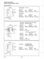
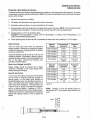
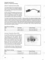
Ignition System Testing
Ignition system components can be individually tested by measuring their internal resistance and insulation to
ground. These checks must be done with a digital volt/ohm meter. Compare the readings obtained to the values
listed on the chart. Actual values may vary up to ± 10% between like components. Any readings outside the span
should be considered questionable.
NOTE: The stator coils can be checked without removing them from the engine. Simply disconnect the connector
plug in the stator-to-COI wire and check the resistance values between the wire colors listed below. Consult the
stator schematics shown on the next pages.
* Indicates a system that incorporates a white COI-to-stator ground wire. These systems will indicate continuity
between the exciter/pulser wires and ground.
PULSER COIL
EXCITER COIL
Value
Check Wires
I
Check Wires
Value
SINGLE CYLINDER MODELS
1985-Current Star/Star LT
Star Lite
BrownlWhite
to Black/Red
123 Ohms
Not Applicable
TWIN CYLINDER MODELS
All EC34-2PM (Pulseless)
BrownlWhite
to Black/Red
164 Ohms
Not Applicable
BrownlWhite
to White
164 Ohms
BrownlWhite
to Black/Red
164 Ohms
BrownlWhite
to White
164 Ohms
.
All EC4O-PUSOPL thru 1989
All EC44-2PM
.
All EC40PUSOPL 1990 to current
EC4SPL (Pulseless)
All ECSOPM 1990 to current
All EC44-3PM (Pulseless)
I
BrownlWhite
to Black/Red
14S0hms
Not Applicable
/
All ECSOPM thru 1989
T
BrownlWhite
to Black/Red
17 Ohms
* Indicates a system that incorporates a white COI-to-stator ground wire. These systems will indicate contin uity
between the exciter/pulser wires and ground.
EXCITER COIL
c
THREE
CYLINDER
MODELS
Check
Wires
Value
Check
Wires
Value
All ECS8PL-01
Black/Red
to Red
4.6
Ohms
White to
White/Red
100
Ohms
All EC60PL and
EC6SPL-01
Black to White
261
Ohms
Red to White
20 Ohms
All
EC6SPL-02/03/0S
Black/Red to
Green
248
Ohms
Red to Green
All EC7SPL-01 and
EC80PL-01
Black/Red
to Green
248
Ohms
Red to Green
Three Cylinder Models:
Secondary Ignition Coil
c
PULSER COIL
EC58PL-01
CONTROL COIL
Check
Wires
Value
20 Ohms
White to
White/Red
96 Ohms
20
Ohms
White to
White/Red
96 Ohms
EC60PL
EC65PL-01
Check
Wires
Value
Green to
Blue
29.4
Ohms
TRIGGER COI L
EC65PL
02103/05
EC75PL-01
EC80PL-01
Primary Resistance
Tab to Tab
.4 Ohms
± 1S%
.106 Ohms
± 1S%
.4 Ohms
± 1S%
.4 Ohms
± 1S%
Secondary Resistance
Tab to Plug Wire End
(Cap Removed)
4 KOhm
± 20%
2KOhm
± 20%
7.S K Ohm
± 20%
7.S KOhm
± 20%
Spark Plug Cap
3.7 to 6.3
KOhm
3.7 to 6.3
KOhm
3.7 to 6.3
KOhm
3.7 to 6.3
KOhm
Secondary coils can also be dynamically tested with a coil power tester such as the Graham Lee Model 31 .
Consult the tester operation manual for specific operating instructions.
4.21
8/94
-j
ENGINE ELECTRICAL
Ignition I Charging System Testing
Stator Schematics
Single C~linders
STATOR
YEL
EC-25-PS
Exciter Coil:
Lighting Coil:
Wire Color
Value
BrnIW to BlklR
123 ohms Vel to W or Brn
Twin
Wire Color
Value
.3 to .6 ohms
C~linders
Lighting Coil:
Exciter Coil:
Wire Color
~
BrnIW to BlklR
164 ohms Vel to W or Brn
Wire Color
~
.3 to .6 ohms
BRN/W BLKJR
BRN
w
Twin C~linder
Pulse Type
YEL
Exciter Coil:
Wire Color
BrnIW to W
EC40/50 PL through 1989 120 Watt
EC44-2PM 120 Watt
Pulser Coil:
Value
164 ohms
Wire Color
BrnIW to BlklR
Value
45 ohms
Lighting Coil:
0
Wi re Color
~
Vel to Brn or W .3 to.6 ohms
Exciter Coil:
Wire Color
BrnIW ·to W
w
BRN/W
BRN
EC50PM through 1989 120 Watt
Pulser Coil:
Wire Color
Value
164 ohms BrnIW to BlklR
Value
17 ohms
Lighting Coil:
Wire Color
Vel to Brn or W
Value
.3 to.6 ohms
0
STATOR
Twin C~ linder
EC44-3PM 200 Watt
EC50-PM 200 Watt
EC40/45/40 PL 200 Watt
Lighting Coil:
Exciter Coil:
VEl/R
BRN/W
8/94
)
Wire Color
BrnIW to BlklR
BRN
4.22
Value
Wire Color
Value
164 ohms
Vel to Vel/R
.2 to.5 ohms
ENGINE ELECTRICAL
Ignition I Charging System Testing
Stator Schematics
Lighting Y to Brn
199211993
2 Cylinder
EC50PL-07 All 500 EFI Pulseless 200 Watt
Battery Charge Coil:
Exciter Coil:
/
/
/
Battery
Charge
Gry to Gry/W
Wire Color
~
Wire Color
~
Brn/W to BlklR
164 ohms
Gry to Gry/W
.2 to .4 ohms
Lighting Coil:
Wire Color
Value
Y to Brn
.2 to .4 ohms
Exciter
Brn/W to BlklR
1994 to Current
2 Cylinder
Battery Charge Coil:
Exciter Coil:
Gry-+-_
Brn/W
Gry/W
EC50PL-07/08 500 EFI Pulseless 250 Watt
-+----jI-lJ--+--+-~----+-_"I"
Wire Color
Value
Brn/W to BlklR
.4 to .8 ohms
164 ohms Gry to Gry/W
Brn/W to Gry/W .2 to .4 ohms
Open to Ground
Lighting Coil:
BlklR
W
Value
~
Wire Color
Y to Brn
Brn/W
Wire Color
.2 to .4 ohms
Y
1993 to Current
Exciter
BlklR to R
3 Cylinder
EC58PL 170 Watt
Battery Charge Coil:
Exciter Coil:
Wire Color
~
Wire Color
~
BlklR to R
4.6 ohms
W to W/R
100 ohms
Lighting Coil:
Wire Color
Value
Y to Y/R
.2 to .4 ohms
4.23
8/94
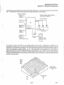
ENGINE ELECTRICAL
Ignition I Charging System Testing
Stator Schematics
Stator
Control
1983-1992
Grn------~~~~~~
~-4-Y
Blu --GoL--------J
3 Cylinder
Exciter Coil:
Wire Color
Blk to W
Lighting Coil:
Wire Color
Y to Brn
or Ground
EC60PL and EC65PL-01/02
Value
261 ohms
Pulser Coil:
Wire Color
RtoW
Control Coil:
Value
Wire Color
.3 to .5 ohms Grn to Blu
~
20 ohms
Value
29.4 ohms
NOTE: All Values are ± 10%
1990-1991
Stator
3 Cylinder
.-'<:>--- G ry
Battery
Charge
'-f>GryIW
Exciter
Exciter Coil:
Wire Color
BlklR to Grn
EC65PL-03 RXL 180 Watt
Value
248 ohms
Lighting Coil:
Value
Wire Color
Y to Brn
.2 to .4 ohms
Open to Ground
Pulser Coil:
Wire Color
R to Grn
Value
20 ohms
Trigger Coil:
Wire Color
Wto W/R
Value
96 ohms
Battery Charge Coil:
Wire Color
~
Gry to GryIW .3 to .5 ohms
Open to Ground
1992 to Current
Y
Lighting
--~r--Brn
Exciter
8
,.--->o--Gry
?<=---I-
'----fJ--
BrnIW
G ryIW
Battery
Charge
Grn R
Bk
Brn
8/94
3 Cylinder
Exciter Coil:
Wire Color
BlklR to Grn
Lighting Coil:
Wire Color
Y to Brn
EC65PL 180 Watt
Value
248 ohms
Pulser Coil:
Wire Color
R to Grn
Value
Trigger Coil:
Wire Color
Value
.2 to .4 ohms
W to W/R
96 ohms
Battery Charge Coil:
Wire Color
~
Gry to GryIW .: .4 to .8 ohms
BrnIW to GryIW .3 to .5 ohms
Open to Ground
4.24
Value
20 ohms
ENGINE ELECTRICAL
Ignition I Charging System Testing
Stator Schematics
1993 to Current
y
B
3 Cylinder
EC75PL-01 Storm 180 Watt
EC80PL-01 Storm
Exciter Coil:
Wire CQIQr
BlklR to Grn
Pulser Coil:
~
Wire CQIQr
~
248 ohms
Grn to Blk
20 ohms
Lighting Coil:
Blk
Trigger Coil:
Wire ColQr
~
Wire CQlor
Value
Y to Brn
.2 to .4 ohms
Wto W/R
96 ohms
Brn
4.25
8/94
ENGINE ELECTRICAL
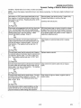
Ignition System Troubleshooting
Condition: No Spark
Disconnect the single black (black/white) wire from the COl Module to
the ignition kill circuit. Does it have a spark?
Yes-+
Not
Check the ignition switch, wire harness, throttle safety switches
and kill switch for proper adjustment or short to ground. Repair
or replace as necessary.
Disconnect the stator to COl module wires. Test the resistance values
of the flywheel coils as per the charts on page 4.21 . Are the resistance values within specs?
All except 3 cylinders: If the parts of the ignition system under
the flywheel check OK, the only remaining component is the
coiVCDI module assembly. Replace the module with another
with the same CU number. (See ignition data)
All 3 cylinders: Disconnect and check the secondary ignition coil
resistances. Refer to the resistance values listed on IVa-1 O. If
the coil resistance values are within specs, replace the COl
module.
Yes-+
Not
Isolate which component's resistance is not within specs. Remove
the flywheel and stator. Recheck the resistances; look for pinched or
bare harness wires; or replace the coil. Refer to page 4.28 for coil
replacement procedures.
Condition: Incorrect Advance/Retard
Follow the engine timing procedure for checking running timing at
3000 RPM. Is the timing within limits?
No-+
Yes t
Adjust the ignition timing by rotating the stator plate to correct the
timing. After adjusting the 3000 RPM timing, continue with
operating RPM timing if poor performance exists. (Continue on
with left column.) See ignition timing page 4.20.
Follow the engine timing procedure for checking operating RPM timing
from page 4.20. Is the timing within limits?
If the 3000 and operating RPM timing are within limits, no other
testing is necessary.
Yes-+
Not
Remove the ignition kill circuit by disconnecting the single black wire Check the ignition switch, throttle safety switches, kill switch and
between the COl module and the machine harness. Is the timing now harness for damage which can cause intermittent shorting
correct?
problems. Correct the problem.
Yes-+
Not
Verify the correct COl module by comparing the CU code on the box
to the information listed in the ignition data charts at the beginning of
this section. Is it the right module?
Replace the module with the correct part and readjust the ignition
timing.
No-+
Vest
Check the resistance of the coils under the flywheel. Compare these
values to the charts on page 4.21. Are they within limits?
Check the wiring connecting the coils and/or replace the coils as
necessary.
No-+
Vest
If the 3000 RPM timing is within limits but the operating RPM timing is
not acceptable, replace the COl module.
NOTE: 3 cylinder engines fire three times per revolution. At 7500 RPM the ignition is firing 21,500 times per
minute. Use of a timing light not capable of handling these RPMs may provide an incorrect operating RPM timing
reading. Use timing light PN 2870630 or equivalent.
8/94
4.26
ENGINE ELECTRICAL
Alternator Output Test - Open Circuit
CAUTION: Perform this test with a digital volt/ohm
meter such as the Fluke 73 (PN 2870659), or
equivalent. Set meter to AC volts (V..-v) when
performing the test.
1.
Disconnect alternator connector from engine.
2.
Insert red test lead into yellow wire coming from
engine alternator.
3.
Black tester lead must be grounded to either the
engine, a brown wire at the connector, or the
yellow/red wire at the plug. See plug wire
identification for proper hook-up.
4.
Start engine and observe AC voltage reading on multitester. Slowly increase RPM to 3000 and note voltage.
The reading should be approximately 20 volts. Readings of 15 to 45 VAC are considered normal. If readings
are low, remove flywheel and look for damaged magnets, shorted or damaged lead wires or damaged lighting
coils. Repair or replace problem component and recheck.
5.
On EFI models AC amps can be checked between Gray and GrayIWhite. At 5,000 RPM reading should be 7
amps.
Lighting System Identification - Test between labeled wires.
Used On:
100 Watt Singles
120 Watt Twins
150 Watt Singles and Twins
200 Watt Twins
1990, 1991 RXL
1992, 1993 500 EFI
180 Watt 3 Cyl. (Carb.)
170 Watt 3 Cyl. (Carb.)
120 Watt 3 Cylinder
180 Watt
1992 to Current 650 EFI
Gray/
White
Gray
GrayIWhite
Check Lighting Coil Between
Yellow and Brown.
Check Battery Charging
Between Gray and GrayIWhite.
250 Watt Twin - 500 EFI
BrownlWhite
Check Lighting Coil Between
Yellow and Brown.
Check Battery Charging
Between Gray and BrownlWhite
and GrayIWhite and BrownlWhite.
Brown
Yellow
NOTE: Gray, GrayIWhite, BrownIWhite are Bullet Type Connectors
4.27
8/94
ENGINE ELECTRICAL
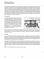
Typical Exciter, Pulser or Lighting Coil Replacement
1.
Remove coil retaining screws and spacers.
2.
Using a pliers, remove epoxy from solder jOints (A)
on the coil to be replaced.
3.
Unsolder connection from coil.
4.
Clean solder terminals (8) on the replacement coil
and re-solder to their proper wires. NOTE: Always
position with numbers towards the outside.
5.
Reinstall retaining screws and spacers.
6.
Using a moisture-proof sealant, seal solder joints
as shown. NOTE: All soldering must be done using
rosin core solder.
7.
Test resistance of each coil prior to stator plate
installation.
NOTE: Lighting and pulseless coils are replaced in a
similar manner.
IMPORTANT: After the stator plate is reinstalled on the
engine, check placement of all coil leads to prevent
possible contact with the flywheel.
8/94
4.28
ENGINE ELECTRICAL
Battery Service
Preparing a New Battery for Service
(
To assure maximum service life and performance from a battery, it must have proper initial servicing. To service
a new battery, the following steps must be taken. NOTE: Do not service the battery unless it will be put into regular
service within 30 days.
1.
Remove vent plug from vent fitting.
2. Fill battery with electrolyte to the upper level marks on the case.
c
3.
Set battery aside and allow it to cool and stabilize for 30 minutes.
4.
Add electrolyte to bring the level back to the upper level mark on the case. NOTE: This is the last time that
electrolyte should be added. If the level becomes low after this point, add only distilled water.
5.
Charge battery at 1/10 of its amp/hour rating.
Example: 1/1 0 of 9 amp battery = .9 amps, 1/10 of 14 amp battery
amps (recommended charging rates).
6.
Check specific gravity of each cell with a hydrometer to assure each has a reading of 1.270 or higher.
Battery Testing
There are three easy tests which can determine
battery condition. Whenever the complaint is related
to either the starting or charging systems, the battery
should be checked first.
Lead-acid batteries should be kept at or as near full
charge as possible. If the battery is stored or used in
a partially charged condition, hard crystal sulfation will
form on the plates, reducing their efficiency and
possibly ruining the battery.
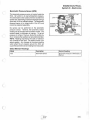
Open Circuit Voltage Test (OCV)
Battery voltage should be checked with a digital
multitester. Readings of 12.6 or less require further
battery testing and charging.
Specific Gravity Test
c
= 1.4 amps, 1/10 of 18 amp battery = 1.8
A tool such as the battery hydrometer (PN 2870836)
can be used to measure electrolyte strength or
specific gravity. As the battery goes through the
charge/discharge cycle, the electrolyte goes from a
heavy, more acidic state at full charge to a light, more
water state when discharged. The hydrometer can
measure state of charge and differences between
cells in a multi-cell battery. Readings of 1.270 or
greater should be observed in a fully charged battery.
Differences of more than .025 between the lowest and
highest cell readings indicate a need to replace the
battery. .
4.29
State Of
Charge
Conventional
Lead-acid
Yumacron
Type
100% Charged
12.60V
12.70V
12.40V
12.50V
12.10V
12.20V
25% Charged
11.90V
12.0V
0% Charged
Less Than
11.80V
Less Than
11 .9V
State Of
Charge*
Conventional
Lead-acid
Yumacron
Type
100% Charged
1.265
1.275
75% Charged
1.210
1.225
50% Charged
1.160
1.175
25% Charged
1.120
1.135
0% Charged
Less Than
1.1 00
Less Than
1.115
75% Charged
50% Charged
,
*at 80° F
NOTE: Subtract .01 from the specific gravity for
electrolyte at 40° F and compare these values to the
chart.
8/94
ENGINE ELECTRICAL
Battery Service
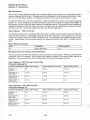
Load Test
NOTE: This test can only be performed on machines equipped with electric start. This test cannot be performed
if the engine or starting system is not working properly.
A battery may indicate a fully charge condition on the OCV test and the specific gravity test, but still not have the
storage capacity necessary to properly function in the electrical system. For this reason, a battery capacity or
load test should be conducted whenever poor battery performance is encountered.
To perform the test, hook a multitester to the battery in the same manner as in the OCV test. The reading should
be 12.6 volts or greater. Engage the electric starter and view the registered battery voltage while cranking the
engine. Continue the test for 15 seconds. During this cranking period, the observed voltage should not drop below
9.5 volts. If the beginning voltage is 12.6 or higher and the cranking voltage drops below 9.5 volts during the test,
replace the battery.
Refilling a Low Battery
The normal charge/discharge cycle of a battery causes .the cells to give off gases. These gases, hydrogen and
oxygen, are the components of water. Because of the loss of these gases and the lowering of the electrolyte level,
it will be necessary to add pure, clean distilled water to bring the fluid to the proper level. After filling, charge the
battery to raise the specific gravity to the fully charged position (1 .270 or greater).
)
Off Season Storage
To prevent battery damage during extended periods of non-use, the following basic maintenance items must be
performed.
1.
Remove battery from machine and wash the case and battery tray with a mild solution of baking soda and
water. Rinse with lots of fresh water after cleaning. CAUTION: Do not allow any of the baking soda solution to
enter the battery or the acid will be neutralized.
2.
Using a wire brush or knife, remove any corrosion from the cables and terminals.
3.
Make sure the electrolyte is at the proper level. Add distilled water if necessary.
4.
Charge at a rate no greater than 1/10 of the battery's amp/hr capacity until the electrolyte's specific gravity
reaches 1.270 or greater.
The battery may be stored either in the machine
Specific Gravity of Electrolyte
Freezing Point
with the cables disconnected, or on a piece of
1.265
-75 0 F
wood in a cool place. NOTE: Stored batteries
-35 0 F
1.225
lose their charge at the rate of 1% per day. They
1.200
-1JO F
should be fully recharged every 30 to 60 days
1.150
+50 F
during a non-use period. If stored during winter
months, the electrolyte will freeze at higher
1.100
+18 0 F
temperatures as the battery discharges. The
+270 F
1.050
chart indicates freezing points by specific gravity.
5.
Charging Procedure
Charge battery with a charger no larger than 1/10 of
the battery's amp/hr rating for as many hours as
needed to raise the specific gravity to 1.270 or greater.
Battery electrolyte is poisonous. It contains acid!
Serious burns can result from contact with the skin,
eyes, or clothing .
ANTIDOTE:
WARNING: The gases given off by a battery are
explosive. Any spark or open flame near a battery can
cause an explosion which will spray battery acid on
anyone close to it. If battery acid gets on anyone,
wash the affected area with large quantities of cool
water and seek immediate medical attention.
8/94
EXTERNAL: Flush with water.
INTERNAL: Drink large quantities of water or milk.
Follow with milk of magnesia, beaten egg, or vegetable oil. Call physician immediately.
EYES: Flush with water for 15 minutes and get prompt
medical attention.
Batteries produce explosive gases. Keep sparks,
flame, cigarettes, etc. away. Ventilate when charging
or using in closed space. Always shield eyes when
working near batteries.
KEEP OUT OF REACH OF CHILDREN.
4.30
o
ENGINE ELECTRICAL
Dynamic Testing of Electric Starter System
Condition: Starter fails to turn motor or motor turns slowly.
NOTE: Assure that engine crankshaft is free to turn before proceeding. For this test a digital multitester must
be used.
With tester on VDC, place tester black lead on battery negative (-) terminal and tester red lead on battery positive (+) terminal. Reading should be 12.6V
or greater. Is it?
No-+
Remove battery, test and/or service. Install a fully
charged shop battery to continue the test.
(Continue with left column)
Yes~
(A) Page 4.32
Disconnect red engagement coil wire from start solenoid. Connect black tester wire to an appropriate
ground and red lead to red harness wire at solenoid.
Rotate ignition key to the start position. Meter
should read battery voltage. Does it?
No-+
With black tester lead on ground, check for voltage
at large relay in terminal" circuit breaker in and out
terminals, and across both sides (red and red/white)
of the ignition switch with switch on start. Repair or
replace any defective parts.
Yes~
Reconnect solenoid, connect tester black lead to
battery positive terminal and red tester lead to solenoid end of battery to solenoid cable. Turn key to
start position. The reading must be less than .1 V
DC. Is it?
No-+
Clean battery to solenoid cable ends or replace
cable.
Yes ~
(8) Page 4.32
Connect black tester lead to solenoid end of battery
to solenoid cable and red tester lead to solenoid end
of solenoid to starter cable. Turn key to start position. The reading must be less than .1 V DC. Is it?
No-+
Replace starter solenoid.
Yes ~
(C) Page 4.32
Connect black tester lead to solenoid end of solenoid
to starter cable and red tester lead to starter end of
same cable. Turn key to start position. The reading
must be less than .1 V DC. Is it?
No-+
Clean solenoid to starter cable ends or replace
cable.
Yes~
(D) Page 4.32
Connect black tester lead to starter frame. Connect
red tester lead to battery negative (-) terminal. Turn
key to start position. The reading should be less
than .1V DC. Is it?
No-+
Clean ends of engine to battery negative cable or
replace cable.
Yes~
(E) Page 4.32
If all these tests indicate a good condition, yet the
starter still fails to turn, or turns slowly, the starter
must be remove for static testing and inspection.
c
4.31
8/94
ENGIN E ELECTRICAL
Electric Starter System Testing (Static)
Starter Motor Static Testing
IGNIT ION
SW ITCH
I GN IT JON SWITCH
SYSTEM
BRN-GROUND
IGNIT ION WIRE COLORS
G TERMINAL - BROWN - GROUND
B TERMINAL - RED - BATTERY
M TERMINAL - BLACK - IGNIT ION
S TERMINAL - RED/WHITE - STARTER
OFF RUN
ALTERNATOR
OUTPUT
~:
R '---
-
- R' W- --
-
RECT IF IER
START
:: ~ :
R
B
R/W
S
R
C I RCU IT BREAKER
(8 AMP )
,/
",,"
IGNIT I ON SW ITCH
COLOR CODE
R 0 RED
BRN 0 BROWN
BLK 0 BLACK
Y 0 YELLOW
R/W 0 RED WITH WHITE TRACER
-.
/
/
(C)
-
-:::::
STARTER RELAY
CHASS IS GNO
- ---- --- - (8)
1
,-- ---- - - --- (E) _ _ ____ __ _ 1
I
I
I
I
:-=-
ENGINE GND
_
-=-
I
1
BATTERY
-
~ _P:!~~E _G~Q
_____ __ J
I
A-E See page 4.3 1
6.
Remove starter motor and disassemble. Mark end covers and housing for proper reassembly.
7.
Remove pinion retaining snap ring, spring and pinion gear.
8.
Remove brush end bushing dust cover.
9.
Remove housing throug h bolts.
10. Slide brush end frame off end of starter. NOTE: The electrical input post must stay with the field coil housing .
11. Slide positive brush springs to the side, pull brushes out of their guides and remove brush plate.
12. Clean and inspect starter components. NOTE: Some cleaning solvents may damage the insulation in the
starter. Care should be exercised when selecting an appropriate solvent. The brushes must slide freely in
their holders. If the commutator needs cleaning, use only an electrical contact cleaner and/or a non-metallic
grit sandpaper. Replace brush assembly when worn to 5/16" (.8 cm) or less.
Starter Housing and Field Coil Inspection
1.
Using a digital multitester, measure resistance between starter input terminal and insulated brushes. The
reading should be .3 ohms or less.
2.
Measure resistance between insulated brushes and field coil housing. The reading should be infinite.
3.
Inspect insulated brush wire and fi eld coil insulation for damage. Repair or replace components as required.
Armature Testing
1.
Using a digital multitester, measure resistance between each of the segments of the commutator. The
reading should indicate .3 ohms or less.
2.
Measure resistance between commutator and armature shaft. Reading should be infinity.
3.
Place armature in a growler. With the growler on , position a hacksaw blade lengthwise 1/8" (.03 cm) above
armature coil laminates. Rotate armature 360°. If hacksaw blade is drawn to the armature on any pole, the
armature is shorted and must be replaced.
8/94
4.32
ENGINE ELECTRICAL
Electric Starter Reassembly and Reinstallation
c
Starter Reassembly
25
1 - Field Coil Housing
2 - Armature Assembly
3 - Washer Kit
4 - Field Coil
5 - Pole Core Set Screw
6 - Brush (+)
7 - Brush Holder
8 - Brush H
9 - Brush Spring
10 - Brush End Frame
11 - Brush End Bushing
12 - Pinion Assembly
13 - Pinion Stopper Set
14 - Through Bolt
15 - Dust Cover
16 - Drive End Frame
17 - Drive End Bushing
18 - Screw
19 - Spring Washer
20 - Engine Mounting Bracket
21 - Stud
22 - Nut
23 - Spring Washer
24 - Washer
25 - Ring Gear
26 - Solenoid
27 - Nut
28 - Spring Washer
29 - Washer
30 - Bolt
31 - Engine Mounting Bracket
32 - Bolt
33 - Nut
34 - Spring Washer
35 - Washer
)
c
o
~
.(
• ~
I
.
/'
~~
~~
V
2.
i ~~\\
\ \
28 29
27 28 27
27
1.
Slide armature into field coil housing.
2.
3.
Lightly gre'ase drive end bushing and install drive end frame on armature.
Mount starter vertically in a vice with brush end up.
4.
While holding negative brushes out against their springs, slide brush plate down onto the commutator.
5.
While holding positive brush springs to the side, slide positive brushes into their holders and correctly position
the springs on top of the brushes.
6.
Using a non-petroleum grease, lubricate brush end bushing and slide it onto end of armature.
7.
Align threaded holes in brush plate and install dust cover and
screws.
8.
Reinstall through bolts and properly tighten all screws.
9.
Lightly grease pinion shaft and install pinion, spring stopper
and snap ring.
Starter Solenoid Bench Test
It is difficult to test the high amp side of the solenoid accurately
on the bench. The only test which can be done on the bench is
the pull in coi l resistance, which shou ld read 3.4 ohms.
Starter Reinstallation
1 . Position starter motor so there is no less than .1 00"
clearance between the ring gear and the starter motor pinion
gear.
(
\
Starter Pinion
Gear
2. Torque 8mm drive end mount bolts to 15 ft. Ibs. (2.07 kg/m).
3. Torque 6mm brush end mount bracket to engine bolts to 5 ft.lbs.
(.69 kg/m).
4. Torque through bolt mount bracket nuts to 30-42 in. Ibs.
4.33
8/94
o
o
Electrical Fuel Injection
Section 4
4.34
ENGINE ELECTRICAL
EFI Introduction and Operation
ROM Identification I Charge Coil Test Specifications
Model
System
Type
ROM 10
ROMPN
Battery Charge Coil Test
Position/Resistance
1990 RXL
I
1990 V2
G to G/W .3 to .5 ohms
1991 RXL
1991 500
I
II
FSM 582
FSM 752
Contact Service
Dept.
4040032
4040033
1992 RXL
I
FSM 582
4040032
1992500
II
FSM 752
4040033
1993 RXL
I
FSM 583
4040036
1993500
1994-1995 RXL
II
I
FSM 762
FSM 581
4040037
4040044
1994500
II
FSM 782
4040043
1995500
II
1995500 V1
4040051
1993-1995 RXL
II
1995650 V1
4040057
G to G/W .3 to .5 ohms
G to G/W .3 to .5 ohms
G to 8/W .2 to .4 ohms
8/W to G/W .2 to .4 ohms
G to G/W .3 to .5 ohms
G to 8/W .2 to .4 ohms
8/W to G/W .2 to .4 ohms
G to G/W .2 to.4 ohms
G to 8/W .2 to .4 ohms
81W to GIW .2 to .4 ohms
G to 81W .2 to .4 ohms
81W to GIW .2 to .4 ohms
G to 81W .2 to .4 ohms
81W to GIW .2 to .4 ohms
G to 81W .2 to .4 ohms
81W to GIW .2 to .4 ohms
Optional ROMs for special applications
ROMID
1992500 V2
Part Number
4040038
Application
1991-1992500
1994650 HE1
4040042
1993-1994 RXL
Description
For repeated lean failures and
lean starts.
For high elevation lean drive
away. Calibrated for ethanol.
NOTE: FSM 581 and 1994650 HE1 can be used for 1991-1992 RXLs, but may experience rich mid-range and
reduced fuel economy.
The machines equipped with Polaris Electronic Fuel Injection (EFI) have many advantages over the normal
carburetor equipped models. The most noticeable improvements wi ll be ease of throttle operation, better cold
weather starting and improved cold engine drive away. The EFI system also compensates for temperature and
altitude, and with minor adjustments will perform well over a wide range of temperatures and altitudes.
To assist technicians in troubleshooting and understanding the EFI, we have divided it into three separate
systems. The following is a short description of these three systems:
System I is battery, battery charging, and how the EFI is powered up or energized.
System" is fuel handling, fuel filtering, and fuel pressure regulations.
System'" is electronics control, which includes the Electronic Control Unit (ECU), ECU inputs from
various sensors, and control of fuel to the cylinders by injector operation.
The following information is a more detailed explanation of the three systems. It's very important during diagnosis
that each of these systems be checked. Failure to do so may result in a reoccurrence of that particular problem.
Basic Operation - System I
Battery, Battery Charging and Powering Up
The battery is the heart of the EFI system, its condition is critical to all EFI function s. Long off-season storage
periods, the high vibrations and extreme temperature variations which are encountered in snowmobile
applications make periodiC battery inspection and service essential.
Some Polaris EFI systems have an alternator or charging system which will produce just enough output to
maintain the EFI system (1990-1991 RXL). If the battery is partially shorted, or if connections offer any high
resistance, the result might be a lean fuel condition.
4.35
8/94
ENGINE ELECTRICAL
Electronic Fuel Injection Data
EFI models have two separate alternators or charging systems. One is used for lighting and accessories, the
other for battery charging and EFI operation. The battery size and alternator size have been designed to provide
adequate output for the EFI system. If your sled is equipped with electric start, a larger battery will be required to
provide adequate cold cranking amperage.
CAUTION: At no time should any accessories be added to the battery or battery side of the charging system. To
do so may overload the system, discharge the battery and cause substandard EFI operation.
To power up or turn on the EFI system, we have utilized different methods. To explain properly, we have to talk
about the two basic EFI types:
TYPE 1- The Type I system is used on all RXLs. To power up requires both key and auxiliary switches to be in the
"Run" position. At that time, a circuit is completed between the battery positive terminal and the brown relay which
passes through the switches and the circuit breaker. The brown relay then connects the battery directly to the
ECU via the fuse link, causing the ECU to begin to function. The ECU connects itself to the battery via the self
shut-off relay, which serves to maintain power to the ECU for approximately ten minutes after power is cut off by
the key or auxiliary switches. The ECU is kept on for a short time in order to help prevent flooding of the engine
during a restart a short time after the engine has been shut off.
When the ECU is first powered up, the fuel pump will run for approximately five seconds in order to build up fuel
pressure in the rail. If the engine is stopped by the switches and then restarted within the ten minute period, the
fuel pump will not repeat the five second run, since the ECU was kept powered up by the self shut-off relay.
If the engine is stopped or dies with the switches in the "Run" position, the ECU will remain powered up until the
battery is drained.
TYPE 11- The Type II system is used on all 500 EFI models. The 1991 and 1992 models power up differently than
. the 1993 and later models. The Type II system is similar to the Type I system in the way that it maintains power to
the ECU after the engine stops, but is different in the way that it powers down. The Type I system depends on the
operator to turn off at least one of the switches before the ECU will power down. The Type II system will power
down regardless of the position of the switches in the event that the engine stops unexpectedly. This preserves
battery power.
1991 And 1992 Model Type II Systems
These systems use a "READY" light on the dash panel to indicate that the ECU is powered up and "ready" to go.
Power to the system does not pass through the auxiliary switch as it does on the Type I system. This switch only
grounds the ignition system like those on carbureted engines. Power to the system is supplied primarily through
the self shut-off relay and the key switch.
The key switch has three positions: OFF, RUN, and SYSTEM RESET/START. In the OFF position, the ignition is
grounded. In the run position, the switch does nothing. It is not connected to any wire in this position. The
SYSTEM RESET/START position is spring loaded, so the switch returns to the RUN position when the operator
releases it. In the SYSTEM RESET/START position battery power is connected to the ECU via the fuse link,
allowing the ECU to initialize and connect itself to the battery using the self shut-off relay. When the key switch is
allowed to return to the RUN position, the ECU is powered only by the self shut-off relay.
If the engine is stopped the ECU will remain powered by the self shut-off relay for a period which varies with engine
temperature. If the engine is warm the ECU will power down almost immediately. If the engine is cold it may stay
powered up for as long as five minutes. The key only needs to be turned to the SYSTEM RESET/START position
if the "READY" light is not on.
1993 And Later Type II Systems
These systems are similar to the earlier Type II systems in function, but do not have a "READY" light or a SYSTEM
RESET/START position on the key switch. The key switch on these models only grounds the ignition in order to
stop the engine. There is no battery power connected to the switch in these models, unless electric start is used.
This system uses and Alternator Controlled Switch (ACS) to power up the system. It is mounted on the battery box
and also houses the voltage regulator/rectifier. This device senses the rotation of the crankshaft by recognizing
output from the engine's alternator. It then connects power to the ECU just as the earlier Type II system does when
the operator turns the key switch to the SYSTEM RESET/START position. This system eliminates the need for a
"READY" light and a complicated key switch. The operator simply pulls on the rope and the system powers up
automatically.
8/94
4.36
-
J
t
ENGINE ELECTRICAL
Battery Maintenance and Testing
Battery Maintenance And Testing
Battery maintenance is of the utmost importance to
ensure satisfactory EFI operation. Partially shorted
batteries can cause an additional load on the charging
system and in turn leave the EFI system with too little
to supply the relays, ECU, fuel pump, injectors, etc.
When this type of machine enters your service area,
be sure to thoroughly clean, inspect and test the
battery.
c
CAUTION: It is extremely important that the battery condition and state-of-charge be maintained at the highest
level possible or serious performance and driveability problems will arise. Battery testing procedures are covered
below.
Off season storage for snowmobiles, especially EFI equipped machines, requires the battery to be removed. In
the summer months we find higher temperatures and higher levels of humidity. These conditions, along with a
small drain applied from the EFI system will in a very short time discharge the battery. Once the battery is
discharged, the plates will become sulfated (turn white), and the battery will no longer accept a charge. Batteries
which are not disconnected, removed and kept charged will need to be replaced at the beginning of each season.
Never substitute any battery of lesser quality when replacement is required.
maintained by using the Polaris Battery Tender PN 2871076.
c
Batteries may be
Battery Service
Conventional battery service techniques apply to this battery. Maintain the specific gravity of the electrolyte to
between 1.270 and 1.300. The open circuit voltage must be maintained to between 12.7 and 12.9 volts DC (at
room temperature), at lower temperatures lower values may be OK. Voltage readings should always be taken
with a fluke meter. The select monitor wi ll place aload onthe battery and on Type I units the monitor will incorrectly
read the low volts (less than 10).
Battery Charging System Testing
1. Adjust digital meter to DC volts and check battery voltage.
Must be 12.4 volts or more (no load). If the select monitor is
bein9 used, the battery has been placed in a load and
readings will be approximately .2 volts lower. Also, the select
monitor on some models will not read accurate voltage below
12.0 and therefore should not be used. Does DC voltage
read correctly?
No-+
Yes ~
Remove the battery. Service and test as outlined earlier
in the engine electrical section. Before continuing, the
battery must be in good serviceable condition and fully
charged. IMPORTANT: Replace battery if questionable.
Yes - See Block 2
Check battery charging coil. Disconnect coil leads.
2. Start engine and increase to at least 4000 RPM. Battery
voltage should increase to 13.6 to 14.6 volts. NOTE: If
Reference specifications for ohms values and
battery is low on charge, the reading will be low. A fully
connections. NOTE: These coils are open to ground,
charged battery will reach the higher number more quickly. Is between any wire and ground should show open circuit.
voltage reading correct?
AC amperage testing will show approximately 7 amps at
4000 to 6000 RPM. Are tests OK?
No-+
Yes - See Block 3
Yes~
No~
3. Charging system is testing OK. Check for any possible
loose connections between rectifier, regulator and battery.
Are there any loose connections?
Replace lighting coi l and/or flywheel. Re-test system.
See Block 1.
No~
4. Replace regulator rectifier and re-test system.
4.37
8/94
ENGINE ELECTRICAL
Power Up Testing - Type I RXLs
Reference correct wiring diagram in chapter 3.
1. Check battery voltage. Must be 12.2 or higher. Use digital
fluke meter. Does it read correctly?
No-+
Yes!
Charge, service, test and/or replace battery.
2. Check EFI brown relay. Y/BK wire should read 12.2 volts
or more with switches turned on. Does it read correctly?
No-+
Yes!
Check circu it breaker, key switch, kill switch, connections
and wires. Check relay ground black wire.
3. Check brown relay. Relay should connect RIY from fuse
link to R/BK (ECU) and R/BLU (select monitor). Does it?
No-+
Yes!
Replace relay and repeat tests.
4. Check self shut-off relay and wires from relays to ECU .
Are tests OK?
No-+
Yes!
Replace wires and/or relays.
5. Replace ECU.
8/94
4.38
ENGINE ELECTRICAL
Power Up Testing - Early Type II, 1991-1992 500's
c
o
1. Check battery voltage. Must be 12.2 or higher. Use a
digital fluke meter. Is voltage OK?
No-+
Yes!
Charge, service and test battery; or replace battery.
2. Check voltage between ECU Orange wire and
ground, and between Y/Blk and ground. With key switch
in the spring loaded position, voltage shou ld read 12.2 or
higher. Is voltage OK?
No-+
Yes!
Check fuse link, key switch RlGR to RfIN, and all wires and
connections between battery to fuse link; fuse link to key
switch, key switch to ECU. Are connections and components
OK?
Yes - See Block 3
No!
3. Test self shut-off relay and circuits to relay. Are
circuits and relay OK?
No-+
Yes!
Repair and/or replace components or wires as needed and
retest.
4. Replace ECU and retest system.
o
".
c
.
4.39
8/94
ENGINE ELECTRICAL
Power Up Testing - Late Type II, 1993 to Current 500's
1. Check battery voltage using digital fluke meter. Must read
12.2 Qr higher. It voltage OK?
No-+
Vest
Charge, service, and test battery; or replace battery.
Continue testing if needed. See battery service.
2. Check voltage to ECU R1GN Pin #106. Should be 12.2 or
higher. Is voltage OK?
No-+
Vest
Check circuit from battery through circuit breaker and to
ECU. Repair and/or replace faulty wiring or
components. Continue to step 3.
3. Check voltaQe to ECU O/BK wire Pin #11 . Should be 12.2
volts while engine is being turned over. Is voltage OK?
No-+
Vest See Also Block 5
Check for signal from battery charge coil to ACS G - GW
wires. Is signal OK? Repair circuit if necessary.
4. Check battery charge coil and connecting wires. Replace
coil and/or repair wires. Continue tests.
Check for volta~e from batterx to ACS.
Is circuit OK?
epair circuit If needed.
Vest
No - See Block 4
Vest
Replace ACS. Is system now OK?
Not
Replace ECU and retest.
Repair relay circuit.
5. Check self-shut-off relay and circuit, OK?
No-+
Vest
6. Replace ECU and retest.
8/94
4.40
ENGINE ELECTRICAL
Power Up Component Testing
Fuse Link
The fuse link is the circuit protection device in Type I
and 1991-1992 Type II electrical system. Should a
system overload such as a dead short occur, the fuse
wire will open the circuit preventing further damage. If
this link should open, find and correct the problem and
then replace the fuse link. Never attempt to replace
the fuse link with a conventional fuse. Use only an
OEM fuse link.
c
Service of the fuse link is limited to verification of
whether or not the wire is continuous. Remove fuse
link from machine and use an ohmmeter to determine
resistance value of wire between plugs. Resistance
values of less than .5 ohms indicate a good wire.
Values greater than that will necessitate link
replacement. Current models will use a self setting
circuit breaker.
Relay Coils
c
The system relay coils are mounted on the front side
of the right footrest assembly on Type I and
1991 -1992 Type II systems. The relays for later
model Type II systems are mounted on the ECU.
Their function is to control a major current carrying
circuit with a smaller, low current carrying control
circuit. When the ECU or ignition switch closes the
low current poil circuit within the relay, the magnetism
in the coil cI ~ses the contact pOints, allowing current to
pass through the relay and power up to the ECU, fuel
pump, etc. Both system types incorporate two blue
relays, one I ontrolling the fuel pump and the other the
self shut-off time delay relay. The Type I system also
uses a bro n relay to control the main power input to
the ECU. n 1993 and later model Type II systems,
the relays a e black.
BLUE
BROWN
Service to relays is limited to measuring pull-in coil
resistance and measuring volt drop across contacts.
The coil resistance should be between 65 and 70
ohms measured between the two pins marked coil on
relay base. When relay is energized, volt drop across
relay contacts should be less than .1 vDC, measured
in parallel with relay. On the bench, the relay can be
checked by hooking the marked relay coil terminals to
a 12v battery and checking resistance of relay
contacts. The resistance must be less than .2 ohms.
o
1993 and later Type II style EFI relays are tested by
placing 12 volts to contact left side as shown in the
diagram to the right. Measuring volt drop across
contacts .1 vDC. Measure resistance of right side
contact. This should be 100 ohms ± 10%.
Right
Left
100
ohms
±10%
Bottom
4.41
8/94
ENGINE ELECTRICAL
Alternator Controlled Switch "ACS"
Shown is the (ACS) for the 1993 to current 500 EFI
systems.
The ACS controls voltage from the
alternator by rectifying from AC to DC voltage current
to charge the battery. It also supplies the ECU with a
12vDC battery voltage signal to indicate that the
engine's crankshaft is turning. The ACS eliminates
the need for the "Ready" light system reset as used on
previous 500 EFI models. NOTE: Even if the key
switch and kill switch are in the "off' position, the ACS
will power up the system if the crankshaft is turned.
(See also page 4.40, Power up testing.)
Test Procedure
With ignition in the on or run position, crank engine over slowly. You will hear the fuel pump run for approximately
five seconds. This tells you the ACS is working. If the fuel pump doesn't work when cranking, disconnect ECU
wire harness and reconnect to reset ECU. Crank engine again. If fuel pump won't start working, unplug the
harness at the ECU and check Orange/Black wire PIN #11 on the ECU harness. Battery voltage should be
present when cranking engine. NOTE: You can also use the select monitor to determine if the ECU is getting
power. If the select monitor display lights up, then the ECU is getting power, check the ACS wire at the ECU plug.
CAUTION: Take care not to distort the pin with your tester lead. If no voltage is present, reset ECU and check
Orange/Black lead at ACS unit. If no voltage is present, check for alternator output or loose connections. If
alternator output is OK, replace ACS.
NOTE: 1994 to current sao's will use a five wire ACS LR36. The extra wire is for a center tap alternator.
\
Cold Starting
Whenever the engine is being cold started, the ECU will select a special "start-up" mode. This will occur any time
the engine is being cold started; for example, any Type I system which has been "key off' long enough for the self
shut-off timer to power down the system, or a Type II system which has had the engine stopped long enough for
the ready light to go off. After turning on the ignition key to reset the system, the fuel pump will run from three to five
seconds to pressurize the system. When the ECU sees the first ignition pulse it provides a longer than normal
"prime" pulse to the injectors to inject enough fuel into the engine for starting. On 1993 and later Type II systems,
there is no ready light or ignition key reset. The pump mayor may not run for the 3-5 second period depending on
how long the engine has been off. In all systems, the "prime" pulse only occurs if the pump runs for the 3-5 second
period.
Once the engine is running the ECU provides a rich cold engine mixture while the engine is warming up. It uses the
engine temperature sensors as an indicator of when the engine is warm enough to start decreasing the fuel to air
ratio. If the key is turned off, the ECU provides power to the self shut-off relay for from ten seconds to ten minutes,
depending upon the system type, and will not repeat the fuel system pressurizing and prime pulse during that time.
Once the self shut-off sequence has expired, the engine will have had sufficient time to cool and the ECU will again
repeat the cold start sequence.
In Type I systems only, during times of severely hard running or in very warm weather if the engine crankcase
should approach a temperature which might result in engine damage the ECU will provide additional fuel to the
engine for cooling. When the crankcase temperature sensor indicates a temperature of approximately 100°C, the
ECU will lengthen the pulse time and cause an over-rich condition which will cool the engine. As soon as the
engine temperature returns to normal, the ECU will return to the original map.
If the engine should become flooded during starting, it can be cleaned out by holding the throttle wide open while
turning the engine over. If the engine is not running , and the throttle is open more than 60°, no fuel will be injected.
The engine will start and will begin receiving fuel from injection when the engine exceeds 800 RPM, or when the
throttle position goes under 60°. The engine should then clean out and run normally.
In Type II systems, the engine is protected against overheating by the engine coolant sensor. If the engine coolant
reaches a threshold (85°C 1993 and later, else 1OO °G) the 'temp" light on the dash will begin to flash. If the engine
coolant temperature continues to increase, the light will begin to blink faster. When the light blinks fast, the ECU
adds fuel to enrich the mixture and to help prevent engine damage. The fuel will continue to be added until the light
stops blinking.
8/94
4.42
ENGINE ELECTRICAL
Basic Operation - System II
c
The fuel system consists of all the parts responsible for storing, cleaning, delivering, pressurizing and injecting fuel
into the engine. They are: fuel tank, fuel pick-up, fuel hose, primary filter, fuel pump, secondary filter, fuel rail,
injectors, throttle bodies, pressure regulator and fuel return hose. Tracing the path of fuel through the system, fuel
is picked up from the bottom of the fuel tank by the fuel pick-up hose and filter. It then travels through a hose to the
primary 75 micron filter, located under the carb air box. Once leaving the primary filter, it travels to the electric fuel
pump, located under the mag end throttle body. The electric fuel pump is responsible for the movement of the fuel
in the entire system. The fuel pump is connected to the battery by a relay. The pump runs continuously whenever
the engine is started. Also located at the outlet end of the pump is a check valve. This valve holds ·pressure in the
system when the pump has stopped.
c
Injector - Side View Cross Section
Injectors,
Screen on
inlet
/
Pressure
Regulator
Return Line
Fuel Rail
c
Throttle Bodies
Weighted Pickup
and Screen
Screen on
Inlet End
Check
Valve
Outlet End
After leaving the pump, the fuel goes through the secondary 10 micron filter for further purification. The secondary
filter is located under the mag end throttle body. As you can see, cleanliness is essential to the operation of the
system, and its importance cannot be overstressed. The fuel is then stored under pressure in the fuel rail, ready
for discharge into the throttle bores. It is necessary to provide consistent pressure and to maintain a specific
pressure in the rail. This is accomplished by the pressure regulator. The pressure regulator is pre-set to maintain
rail pressure at a desired or specific pressure. Any pressure greater than the set pressure is relieved or returned to
the tank by a return line.
4.43
8/94
ENGINE ELECTRICAL
EFI Fuel System Maintenance and Testing
Tank, Hose And Filters
STANDARD FUEL HOSE
The fuel tank is the reservoir for the fuel. It contains a
flexible hose with a weighted pickup and a course
screen which drops to the lowest part of the tank
regardless of machine attitude. Fuel trav~ls through
the urethane fuel hose to the primary 75 micron filter
located under the airbox and then to the fuel pump.
From the pump the fuel hose changes to a reinforced
rubber hose which carries fuel to the secondary 10
micron filter located under the throttle bodies, and
then to the fuel rail.
REINFORCED
PRIMARY FILTER
The fuel tank, hoses and filters require little, if any, service. Periodically inspect tank and hose condition. Assure
that the pickup is clean and properly positioned and vent tube is properly routed and not kinked or pinched.
Replace any hose showing signs of deterioration. Replace primary and secondary filters at 5000 mile (8000 km)
intervals, every two years, or more often if contamination of any kind is present in the system. Use OEM parts only.
If for any reason, at any engine RPM, the fuel system should fail to deliver a sufficient quantity of fuel to meet
engine requirements and have some fuel returning to the tank, the fuel hoses must be checked for obstructions
and/or the fuel filters replaced. If the problem does not rectify itself, proceed to fuel pump testing.
J
CAUTION: Whenever inspection reveals worn, damaged or defective parts, replacement is necessary in order to
avoid serious damage to the machine or injury to the operator.
Fuel Pump
The electric fuel pump is located on the bulkhead
underneath the mag end throttle bore. The 12v pump
receives fuel from the fuel tank, then sends it through
the small strainer in the pump inlet nozzle, through the
roller vane type pump, through the outlet check valve
and on to the injector rail. The pump is completely
filled with fuel during operation. This provides cooling,
corrosion protection and lubrication.
Pump
Outlet
t
Strainer
CAUTION: Never run the pump without a sufficient
supply of fuel or pump damage will result. The pump
is cooled and lubricated by fuel.
Armature
The pump outlet pressure can reach as much as 70 psi. It is regulated however to 35 to 37 psi by the fuel rail
pressure regulator. Located near the outlet end of the pump is a check valve. The pressure regulator also acts as
a check valve. There will be high pressure fuel between these two valves.
The fuel pump is a sealed unit. No internal repair of the pump components can be performed. Pump condition can
be verified by an amp draw test, an output volume test and an output pressure test.
Amp Draw Test: Install a DC ammeter in series with the purple pump power feed wire. The draw should be 2.5
amps. A draw at or slightly less than that value indicates the pump is electrically sound. No draw indicates either
no power present or an open circuit in either th e pump or its ground. A draw greater than that value indicates either
a stuck or defective pump. A pump which is stuck due to long periods of non-use can occasionally be freed by
striking with a soft face hammer. If this does not free the pump, it must be replaced.
Output Volume Test: The output volume of the fuel pump and delivery system can be verified with an output
volume test. To perform test, start machine and make sure delivery side of system is filled and pressurized to the
pressure regulator. With machine turned off, disconnect fuel return hose and place it into a 200 milliliter graduated
container. Activate ECU to cycle pump for approximately five seconds. The measured output during this time
period should not be less than 90 to 100 milliliters. NOTE: Battery voltage less than 12.6vDC or restrictions in the
fu el lines or filters will cause output to be less than recommended amount.
8/94
4.44
, *.
ENGINE ELECTRICAL
Fuel System Maintenance and Testing
c
Output Pressure Test: Install EFI fuel System
pressure tester (PN 2870982) in fuel line on PTa end
of rail. NOTE: Use caution when removing hose. The
rail may contain pressurized gas if engine has been
recently run. Activate dealer mode using select
monitor service harness plug, by connecting gray and
black test loads together or by jumping gray and black
wire terminals at diagnostic plug, then turning on
ignition switch. With pump running, system pressure
should be between 35 and 37 psi. A pressure reading
of higher than normal indicates a faulty pressure
regulator or an obstructed fuel return hose. A
pressure reading lower than normal indicates a faulty
pressure regulator, a bad pump, or a restriction in fuel
hoses or filters between tank and rail. If pressure
starts out normal and then gradually lowers, suspect
the fuel tank vent and/or any of the fuel filters or hoses
which may restrict fuel delivery to the pump.
Fuel pressure can also be checked with the gauge in
place and with the engine running. Pressure should
be checked at both idle and at operating RPM. A
plugged filter may show good pressure at idle but
restrict flow at operating RPM.
Fuel Rail
The fuel rail is the fuel distribution manifold for the
injectors. The injectors slip into fittings on the
underside of the rail which are sealed with a-Rings
around the injectors. The rail stores fuel under
pressure so that simply opening the injectors will allow
fuel to pass from the fuel rail through the injectors and
into the throttle body. Pressure in the fuel rail is
controlled by the pressure regulator.
The fuel rail requires little if any service. Periodically
inspect seal between rail and injectors and rail and
regulator. If any leakage exists, replace a-Rings and
recheck for leaks.
Return Hose
The return hose runs between the bottom of the
pressure regulator and the top of the fuel tank. It
provides a path for excess fuel from the fuel rail to
return to the fuel tank. If this hose should become
obstructed in any way, the excessive fuel pressure in
the rail will cause a rich operating condition.
Pressure Regulator
The fuel pressure regulator is mounted on the
opposite end of the fuel rail from where the fuel enters.
Its function is to maintain a consistent fuel pressure
within the rail by allowing pressure above the desired
level to bleed off the rail , through the regulator, and
back to the tank by way of the return hose. When the
fuel pressure on the bottom of the regulator
diaphragm reaches between 35 and 37 psi, it
overcomes the spring on the other side of the
diaphragm and pushes it up. This opens the valve to
the return hose, allowing fuel to escape and
maintaining a specific pressure.
4.45
8/94
ENGINE ELECTRICAL
EFI Fuel System Maintenance and Testing
The regulator can also vary pressure consistent with
engine load, atmospheric pressure, etc. A manifold
pressure tube runs between the mag end throttle body
and the top of the diaphragm. As the throttle is
opened, the pressure in the throttle bore rises. This
additional pressure enters the cavity above the
diaphragm, assisting the regulator spring and raising
the pressure in the rail, allowing more fuel through the
injectors while they are open due to the higher
pressure. The opposite is true during deceleration.
High engine vacuum while the butterflies are closed is
applied to the top of the diaphragm, allowing the fuel to
compress the spring and open the regulator valve at a
lower pressure. These pressure changes are very
small and tend only to maintain a specific pressure
differential between the throttle bores and the fuel rail,
and not to vary mixture ratios while driving.
Fuel
In addition to checks made under fuel pump service,
the pressure regulator span can also be checked.
With a fuel pressure gauge on the fuel line and a
Mity-Vac™ pump (PN 2870975) installed on the
regulator, activate the system the same as was done
for the fuel pump check. The fuel pressure at
atmospheric pressure should read between 35 and 37
psi; with five inches of vacuum it should be between
33 and 35 psi; with ten inches of vacuum it should read
between 30 and 32 psi; and with five pounds of
pressure it should be between 42 and 44 psi.
Consistent readings outside the span indicate a bad
regulator, bad hoses or filter, bad fuel pump, or an
inaccurate test gauge. Verify the problem and correct
it before any additional work is done to the system.
Injector
The injector is an extremely close tolerance solenoid
type valve which opens and closes electrically. It
allows fuel to pass from the fuel rail through the
injector body and into the throttle body. The quantity
of fuel is controlled by the length of time each injector
is open, and constant fuel rail pressure.
Filter
8/94
4.46
ENGINE ELECTRICAL
EFI Fuel System Maintenance and Testing
\
1. Check battery voltage. Must be 12.2 or Charge, service, test and/or replace
battery. See battery service section.
higher and be capable of handling pump
load. If not, the fuel rail pressure test will
below.
No -+
•
Yes~
Connect fuel pressure gauge and test as
earlier outlined. Must read 35 to 37 psi.
Pressure reading high-+
Pressure reading low ~
Check for pinched or kinked
pressure regulator return line. Is line
OK?
No-+
Inspect pump pickup lines, filters and
volume test pump. Is volume OK?
No -+
Replace pressure regulator.
Clean or replace return line.
Yes ~
c
Yes~
Replace pump.
NOTE: It is very important to inspect fuel tank pick up screen and tank for floating plastic particles. It's possible to
have particles collect around screen as pump is running and float away after pump has stopped running.
o
c
4.47
8/94
ENGINE ELECTRICAL
EFI Fuel System Testing
Injectors cannot be disassembled for service or cleaning. If a cylinder is not functioning properly and fuel supply is
suspected as the cause, determine if an injector problem exists and whether it is mechanical or electrical. Switch
the harness leads from the injector in question with an adjacent injector. If the problem moves to the adjacent
injector, then it is electrical (see injector electrical service). If the problem stays with the same injector, then the
problem is mechanical and injector replacement is necessary. If one of the cylinders fills with fuel after shutdown
and the rail empties, remove airbox, open throttles, install a 1" (2.5 cm) wide strip of cardboard above butterfly and
close throttles. Turn on ignition to pressurize rail. Wait two minutes and remove cardboard. Some wetting is OK,
but a soaked cardboard indicates a defective injector. Some of the mechanical problems which will necessitate
injector replacement are internal and external leakage, partial or total fuel blockage, open injector coil, and
physical damage to the pintle and pintle case.
Throttle Body
The throttle body assembly replaces carburetors in a
fuel injected type engine. It consists of one throttle
bore unit for each cylinder which has the air flow
controlled by a butterfly type throttle shutter. On top of
each unit one injector is held in place by the fuel rail.
The throttle position sensor is mounted on the mag
end of the throttle body assembly. Engine idle RPM is
controlled by the throttle stop screw mounted
between the mag and center throttle bore units.
Synchronization of the throttle assembly is
accomplished by synchronizing adjuster between
each pair of throttle bore units.
THROTTLE STOP
REGULATOR
Since each cylinder and throttle bore operates independently and the only common factor is that they all get the
same quantity of fuel, it may be necessary to periodically synchronize the throttle butterflies to coordinate the
fuel/air quantities. This is best accomplished by removing the throttle body and visually synchronizing the
butterflies on the bench.
Procedure
Loosen synchronizer jam nut between mag and center cylinder. Turn adjuster until center and PTa butterflies are
farther open than mag side. While shining a flashlight into bore on engine side, view through air box side of mag
throttle bore. Back out throttle stop screw until butterfly just closes at top of bore (no light shining through). Moving
flashlight to center bore, adjust synchronizer until center butterfly just closes at top of bore. NOTE: Make sure the
PTa butterfly does not hold the center open while adjusting.
Once center and mag butterflies are set to a just closed position, synchronize PTa butterfly the same way by
adjusting synchronizer between center and PTa throttle bores until PTa butterfly is just closed. Open and close
throttle three or four times by pulling up on cable attaching point on throttle shaft. Recheck all three butterflies to
verify synchronization and readjust if necessary. Make sure that all synchronizer jam nuts are tight. Reinstall
throttle body assembly on engine. The method for adjusting the throttle position sensor will be discussed under
TPS.
.
NOTE: The same procedure can be used on twin cylinder engines.
8/94
4.48
ENGINE ELECTRICAL
System III - Electronics Operation
c
The Electronic Control System is the mixture control part of the system. It uses sensor inputs to control the fuel/air
ratio. The illustration shows the components of the basic Electronic Control System.
Sensors (Inputs)
(Three Cylinder System Shown)
Twins have 2 injectors
Injectors (Outputs)
ECU
Drop Resistor
In From
Battery
L......,,.....-----I
Output
(Type II Systems Only)
D
0 0
DO
Select
Monitor
c
The electronic control unit delivers a low voltage signal to each sensor. Depending on variations in air
temperature, throttle position, etc., each sensor will vary the amount of that signal passing through it to ground
depending on its position and temperature. The ECU reads the information and from that determines what the
actual air temperature, throttle pOSition, etc. is. This information is then plotted on a map which is
pre-programmed on the PROM (Programmable Read Only Memory) or "chip". Based on the two primary inputs;
RPM (x) and throttle position (y), the ECU can select a specific injector open time (z). This value is the distance
between the base plane and the map at the point where x and y cross. The value is converted to milliseconds and
referred to as pulse width.
c
Simulated
prom
map
Pulse Width
(in milliseconds)
(z)
o
RP
Throttle Position
M
(y)
(x)
4.49
8/94
ENGINE ELECTRICAL
System III - Electronics Operation
Input from the other sensors either adds to or subtracts a percentage from the pulse width to tailor the fuel/air ratio
for the specific altitude, air temperature and engine temperature. See illustration.
Richer for low altitude,
cold engine, cold inlet
air, etc.
[J .
]
Leaner for warm air
temps, high altitude etc.
./
./
"
"
)
....... Pulse Width Z
)
........
./
........
Throttle Position Y
The illustration below depicts pulse widths in milliseconds output by the ECU. Figure A shows a situation where
the air temperature is low, the machine is at low altitude with a cold engine, wide open throttle and high RPM.
The ECU determines the engine's fuel requirements and selects a relatively long pulse width which allows more
injector open time for fuel to enter the engine.
ON r - - - - - ,
I
Figure A
OFF
Long Pulse Width (i.e. High RPM, Cold Temps., Low Altitude, etc.)
Figure B
ON
OFF
n
n
'-------'
Short Pulse Width (i .e. Idling, Warm Temps., High Altitude, etc.)
If the same engine were at high altitude on a warm day at low RPM and throttle settings, the ECU would select a
pulse width closer to Figure B, indicating a shorter injector open time and less fuel entering the engine. In this way
the system can ultimately vary the mixture for all temperatures, loads and altitudes by varying the amount of time
the injectors are open per revolution.
8/94
4.50
)
ENGINE ELECTRICAL
System III - Electronics Testing
Select Monitor
The select monitor (PN 2870969) is designed to
provide easy, accurate diagnostic and service
information to the technician. When installed on the
machine it will provide both dynamic and static
displays of the function of critical fuel system control
components. It also has the ability to display the
contents of the ECU memory. With this tool, electrical
service of the EFI system should be quick and easy.
c
Remove protective plug from diagnostic plug in
machine harness next to ECU. Connect select
monitor to instrument harness, to service harness,
and to diagnostic plug in. Install program cartridge
into select monitor. Turn on ignition switch and place
handlebar kill switch into run position. Turn on select
monitor switch. On most models the monitor display
will now light up.
NOTE: On 1993 500 models, it is necessary to
connect the Red/Yellow and Yellow/Green wire in the
5 pin electric start coupler with a jumper wire to
maintain power to the ECU and select monitor. Type I
models will stay powered up with switches on. On
Type II systems, the time will be limited unless the
engine is running. On 1994 and later models, the ECU
will remain powered for approximately one minute at
room temperature and above.
SERVICE HARNESS '
There are two ways to search for information with the
monitor. You can scroll through the different modes in
order until the correct information is found, or you can
select the specific mode letter and number and
advance to the specific information that you want.
Electronic Control Unit
The Electronic Control Unit (ECU) is the brain of the
EFI system. It is a digital computer which holds the
memory chip for the read out of basic injector opening
duration on a three dimensional map. There are two
ECU systems used, Type 1 for the RXL and Type 2 for
the 500 EFI snowmobiles. Each system receives the
same type of information from the sensors. The ECU
incorporates a number of special features. Some of
these features are: adjustable low speed mixture
control, automatic cold engine start up enrichment,
engine over temperature protection, flooded engine
cleanout mode, failsafe feature and LED self
diagnostic system. In the event that any sensor
should give inaccurate or no information, the ECU will
then flash a coded light sequence to identify the
affected sensor. NOTE: It is important to note that the
ECU will not identify mechanical problems. Only
sensor inputs are monitored. For example, low fuel
pressure or lack of fuel will not be diagnosed.
The ECU can only tell if a sensor reading is within a
specific range. For example, a failure code will not be
indicated if throttle position shows 3.9 when the
throttle is actually wide open. Use display of throttle
pOSition to ensure the readings reflect actual
conditions.
This same concept applies to the
temperature sensors and the barometric sensor.
"
ECU Part Numbers
Type I w/o chip
Type I w/o chip Elect. Start
Type II w/o Chip
2410028
2410029
2410030
0
4.51
8/94
.
.....
.~
ENGINE ELECTRICAL
System III - Electronics Testing
ROM Chip Removal and Installation
The chip can be removed and replaced with the
appropriate chip puller and installation tool. You will
need to supply ROM Removal Tool (Digi-Key PN
K158-ND; Call 1-800-344-4539); and Nyogel (Polaris
PN 2871 044). Note the location of the indicator notch
when replacing the chip (see photo). The system will
.not function with the chip in backwards or with the chip
pins not properly in their sockets.
See the
specification section in this chapter for chip
information.
NOTCH
CAUTION: The computer chip and the ECU are
extremely sensitive to static electricity. The handling
of either component in a static electricity environment
will cause irreversible damage. Work on a metal
bench or other static dissipating surface. It is very
important that you ground yourself by touching the
crystal inside the ECU before any internal service
work begins on the ECU assembly.
See the
Illustrations 1 and 2. Ifthe ECU has not been removed
from the machine, be sure to unplug it before
proceeding.
1.
Disconnect main harness ·connector from ECU.
Remove phillips head cover screws and cover.
2.
Touch the crystal located inside the ECU box to
ground yourself before proceeding.
See
Illustrations 1 and 2. CAUTION: The chip and the
ECU are very sensitive to static electricity.
Working inside the ECU without grounding
yourself may cause irreversible damage to either
or both components.
3.
In the event you are removing an old chip for
replacement, place ROM removal tool (Dig i-Key
PN K158-ND) over ROM chip. Pull up on triggers
to securely grasp chip and pull chip out.
4.
Check charts on page 4.35 to be sure you are
installing the correct ROM.
5.
Coat the pins of the ROM with a light coating of
Nyogel (Polaris PN 2871044).
6. Carefully insert the ROM, making sure the notch
on the end of the ROM matches the notch
indication mark drawn in white on the circuit
board. See illustrations 1 and 2. CAUTION: If the
chip is installed with the notch incorrectly
positioned the chip will be ruined and the machine
will fail to run.
Align cover gasket, positioning cover rubber
bumper above chip. Reinstall cover screws and
reconnect wire harness. Install select monitor
and check functions.
8/94
4.52
FSM5631
Connector
White line on board
e sure notch on ROM is
positioned here
Crystal - touch before
performing service to
ground yourself
[X/
RXL ECU Box
III. 1
@
@
IX
Crystal - ___
touch before
White line
performing
on board
service to
ground yourself
Be sure notch on ROM
chip is positioned here
Connector
7.
500 ECU Box
111.2
@
(
ENGINE ELECTRICAL
System III - Electronics Testing
C
Troubleshooting EFI System
When key switch is turned to the on position, voltage is supplied to ECU and the select monitor. NOTE: Some
models will require the engine to be turned over.
As explained on page 4.36, after the ECU is powered up, it will run the fuel pump for five seconds, read the sensors
and do a self diagnosis of the complete system. The ECU does not check the Air Temperature Sensor (ATS) until
the engine RPM is above 1000.
With a good understanding of how each component functions, the test procedures given in this manual, and the
use of the select monitor, you will be able to service and diagnose the Polaris fuel injection system. All information
and specifications are on the latest product information available.
C
Select Monitor Scrolling
With the ignition on and the monitor hooked up and turned on as described earlier, the display should show the
year and the mode (FOO). By pressing the. key, the display will proceed to (F01) which is the model. Press the.
again and the (F02) will appear, which is battery Voltage. By pressing the. or T keys, you can either scroll
forward or backwards through the modes.
If you know the mode you want, service time can be saved by pressing uP' followed by the two digit number, and
enter. The monitor will display the mode number and the registered information.
The following chart shows the modes, what the readings are for, and what an approximate reading should be.
Mode
Description
Normal Reading
FOO
Model Year
Year of machine (not always correct)
F01
Engine Code
Polaris code number 30 for Triples; 20 for Twins
F02
Battery Voltage
12.2 or above at room temperature
F03
Engine RPM
Idle: 2000 to 2200 3 Cylinder; 1600 Twins
F04
Throttle Valve Angle (Whole Range)
0° to ?JO large steps
F05
Intake Air Temp in C o
Room temperature (engine cold)
F06
Intake Air Temp in FO
Room temperature (engine cold)
FO?
Crankcase Temp in Co
Room temperature (engine cold)
F08
Crankcase Temp in FO
Room temperature (engine cold)
F09
Barometric Sensor
Barometric pressure in millimeters of mercury
F14*
Throttle Valve Angle (Low End)
0° to 35.9 ° small steps
F21
MR (Idle Mixture) Position
2.5 or more than 4.0 for Alt. See page 4.58.
F22
Water Temp Sensor in Co
Same as ATS or CTS Cold or 30° to 90 ° running
FAO
Ignition Key Diagnostic
KY + No.3 LED (with key on)
FA1
Dealer Mode
OM + No.5 LED (with OM activated)
FA2
Relay Check
FP,SD,SS + No.1 ,2, and 3 LED when operating
FBO
Existing Trouble Codes
Faults presently existing
FB1
Memory Trouble Codes
Faults that are intermittent
FCO
Memory Clear
-
"Not used on 1990 Type I systems
4.53
8/94
ENGINE ELECTRICAL
System III - Electronics Testing
The ECU determines the amount of fuel to be injected by accurately calculating the engine's needs for fuel
delivery. In order to do this, the ECU is loaded with a memory chip for the read out of the three dimensional map
which reads the throttle sensor and engine speed. Various sensors such as air temperature sensor, coolant
temperature sensor, barometric pressure sensor, battery voltage and the MR setting in the ECU are also inputs to
control fuel delivery.
Select Monitor Readings
Mode
Description
Normal Reading
F100
Model Year
Year of machine
F01
Engine Code
Polaris code number 30 for Triples
Polaris code number 20 for Twins
F02
Battery Voltage
12.2 or above
NOTE: Type I system will indicate a f1iQh battery voltage on the select monitor if the actual voltage is below
approximately 10vDC. If you suspect a low battery, use a Fluke meter to directly measure the battery voltage.
Type II systems do not have this problem. The select monitor accurately reads battery voltage.
RPM Sensor
The Electronic Control Unit receives an engine RPM
signal from the COl box. This signal is one of the main
inputs and is \(~ry critical to proper operation. If the
ECU does not see this' signal, the injectors will not
open and the fuel pump will only cy~le for the initial five
seconds when the ECU is powered up. (See page
4.36).
''"'RPM OUTPUT
The ignition switch anq, aux11iary kill switch are
connected in series wi h t he E0U COl signal. If these
switches are leaking partial voltages to ground, the
ECU will not function properly. Whenever COlor
intermittent running problems are occurring, the
switches should be suspect for potential problems.
These switches will also fail more often when humidity
is high. To troubleshoot the switches, disconnect or
isolate them from the circuit.
Select Monitor Readings
Mode
Description
Normal Reading
F03
Engine RPM
Cranking 300-500
8/94
4.54
• r.
ENGINE ELECTRICAL
System III - Electronics Testing
Throttle Position Sensor (TPS)
c
Throttle position is one of the two main inputs used to
calculate fuel/air ratio. The throttle position sensor is
a rheostat type variable resistor which is mounted on
the end of the throttle shaft. The resistance value of
the sensor is relatively low at idle. As the throttle is
opened, the resistance goes up proportionately to the
butterfly angle. The ECU passes a specific current
through the sensor and experiences more current
flow at idle. This flow lessens as the throttle is
opened.
From this information, the ECU can
determine butterfly angle and control fuel delivery
accordingly.
The throttle position sensor can be checked on the bench with an ohmmeter. With the butterflies closed, the
resistance between the black and white wire, measured at the plug, should be between 400 and 700 ohms. With
the throttle wide open, the resistance should be approximately 4.5 k ohms. Some minor variations in resistance
values will be experienced due to throttle position sensor location; but radical differences or failure to see a
consistent progressive increase or decrease in the resistance as the throttle is opened and closed indicate a
defective position sensor. The sensor can also be checked with the select monitor using mode F04. It should read
between 3 0 - 4 0 when the throttle is closed and consistently, progressively increase with throttle opening to more
than 74 0 at WOT. The throttle position sensor can be replaced by removing the two mounting screws and gently
prying it off the end of the throttle shaft.
During periodic inspection, or when replacing the TPS, it must be synchronized to the throttle butterflies. The
sensor must be positioned to the positive side of 0 with the butterflies totally closed. To adjust the sensor,
disconnect the throttle cable from the throttle flipper and back out the throttle stop screw until the butterflies are
~ closed. Connect the select monitor to the system diagnostic plug. Turn on the ignition switch and the
monitor on/off switch. Scroll the monitor to mode F04 or F14 and verify the sensor positioning. NOTE: F14 is a
low end scale for sensor adjustment. This is the desirable scale, but because of programming may not work on all
models. Loosen the sensor mounting screws and rotate the sensor until the reading on the monitor is .1 on F14,
or the point where the reading "breaks over" between 0 and a positive number on F04. Tighten the mounting
screws, open and close the throttle a few times and recheck the reading. Readjust if necessary.
0
0
0
Select Monitor Readings
Mode
Description
Normal Reading
F04
Throttle Valve Angle-Range
00 to
Large Steps
See TPS Adjustment
F14
Throttle Valve Angle Low End
Not Used on All Systems
00 to 35° Small Steps
Depending on Position
4.55
7r
8/94
ENGINE ELECTRICAL
System 111- Electronics Testing
Intake Air Temperature Sensor (ATS)
The air temperature sensor is mounted in the air box.
Its function is similar to the crankcase temperature
sensor in that its temperature will vary the resistance
across the sensor. It has a reduced thermal capacity
for quicker response.
Cold air will cause high resistance and warmer air will
lower the resistance. The ECU sends current to the
sensor and, depending on its temperature, a certain
amount will pass through to ground. By measuring
how much passes through, the ECU can calculate air
inlet temperature and vary fuel/air ratio accordingly.
The intake air temperature sensor can be tested in a manner similar to the crankcase temperature sensor.
Determine the approximate temperature of the sensor, measure the resistance between the two lead ends at the
plug and compare the reading to the graph shown on the bottom of page 4.59. An easier and more accurate
method is to use the select monitor to indicate what air temperature reading the ECU receives from the sensor. If
the air box and underhood area have not been warmed due to recent running of the engine, the air temperature
sensor should read room temperature on the select monitor. Radical differences between room temperature and
the indicated reading indicate a problem with the sensor, wiring, battery, or ECU. Verify and repair any problem
before attempting to operate the machine.
Select Monitor Readings
Mode
Description
Normal Reading
F05
Intake Air Temp °C
Room Temp "Engine Cold"
F06
Intake Air Temp OF
Room Temp "Engine Cold"
Crankcase Temperature Sensor (CTS)
The crankcase temperature sensor is screwed into
the upper crankcase half below the mag throttle bore.
This thermistor type semi conductor varies in
resistance depending on its temperature. The ECU
delivers an electrical current to the sensor. When the
sensor is cold, its resistance is high and not much
current passes through the sensor to the engine
ground. As the sensor heats up its resistance lowers,
allowing more current to pass through. The ECU
measures the current flow through the sensor and
knows the temperature of the engine crankcase and
can vary fuel ratio according to case temperature.
';
The CTS is used on all Type I systems and on 1991
and 1992 model Type II systems. 1993 and later Type
" systems do not use crankcase temperature sensor.
Select Monitor Readings
Mode
Description
Normal Reading
FO?
Crankcase Temp °C
Room Temp "Engine Cold"
FOB .
Crankcase Temp OF
Room Temp "Engine Cold"
8/94
4.56
ENGINE ELECTRICAL
System III - Electronics
c
Barometric Pressure Sensor (BPS)
The barometric pressure sensor is located inside the
ECU. Its function is to read atmospheric pressure.
This information is then used by the ECU to determine
fuel/air ratio, depending on pressure changes during a
given day, or for any altitude change. The barometric
pressure sensor is an integral part of the ECU and
cannot be replaced separately.
CHIP
PRESSURE
SENSOR
No service can be performed on the barometric
pressure sensor. However, the barometric sensor
reading can be checked with the select monitor. The
monitor reads in millimeters of mercury. To get air
pressure in inches of mercury, divide this number by
25.4. Compare the reading to an accurate barometer.
NOTE: Readings reported by the radio or television
are corrected to sea level. The select monitor is an
actual reading. Any changes to the stock machine
which affect the air pressure around the ECU will
cause the barometric sensor reading to be inaccurate.
Select Monitor Readings
Mode
Description
Normal Reading
FOg
Barometric Sensor
Barometric Pressure in Millimeters of
Mercury
4.57
8/94
ENGINE ELECTRICAL
System 111- Electronics
MR Adjustments
Fuel/air ratio at engine RPMs below 3500 can be adjusted Slightly richer or leaner from the standard program
mixture by adjusting the MR control. This adjustment is to compensate for individual engine differences on Type I
and 1991 and 1992 Type II systems. This adjustment affects the same area as an air screw on a carbo
To adjust the MR control, remove the rubber plug. Install the select monitor, power up the system and press
buttons F-21 . A correct reading on the monitor is between 2 and 3, with 2.5 being the most desirable. NOTE: At
high altitudes, a higher number will result in earlier drive-away after startup. Turning the MR screw clockwise will
increase the observed number and richen the mixture. Turning the screw counterclockwise will lower the number
and lean the mixture. The leanest setting will be 0 and the richest will approach 5.
Type II System - 1993 To Current
The production setting is 2.5. Adjusting the MR control screw on 1993 to current model 500s will only affect cold
starts and cold drive-away. (It is designed to assist the driver when using poor or summer grade fuels.) If a lean
condition is suspected, change the number to a higher value. If a rich condition is suspected, change to a lower
number. Approximately two minutes after starting, this adjustment has little effect; after 10 minutes it has no
effect.
Select Monitor Readings
Mode
Description
Normal Reading
F21
Mixture Enrichment
2.5
MR Adjustments For Altitude And Temperature
The following tables list MR screw settings for various temperatures and altitudes. Whenever performing MR
adjustments, take the operator's riding location and weather conditions into account before making an
adjustment. Numbers anywhere within the ranges listed should provide acceptable operation.
Type I Systems - 1990 Through Current Rxls
Production Settings 2.5
Ambient Temperature
Below +20°F (-6°C)
+20° to +50°F (_6° to 10°C)
Above +50°F (10°C)
0-3000 Ft. or
0-900 m
2.5
3.0-3.5
3.5-4.5
3000-6000 Ft. or
900-1800 m
3.0-3.5
3.5-4.0
3.5-4.5
6000-9000 Ft. or
1800-2700 m
3.5-4.5
4.0-4.5
4.5
9000-12000 Ft. or
2700-3700 m
3.5-4.5
4.0-4.5
4.5
.
Type II Systems - 1991-1992 500 EFls
Production Settings 2.5
Ambient Temperature
Below +20°F (-6°C)
+20° to +50°F (_6° to 10°C)
Above +50°F (10°C)
0-3000 Ft. or
0-900 m
2.5
2.5-3.5
3.0-4.0
3000-6000 Ft. or
900-1800 m
2.5
3.0-4.0
3.5-4.5
6000-9000 Ft. or
1800-2700 m
2.5-3.5
3.0-4.0
3.5-4.5
9000-12000 Ft. or
2700-3700 m
2.5-3.5
3.0-4.0
3.5-4.5
8/94
4.58
ENGINE ELECTRICAL
EFI Electronics
Type II System - 1991 To Current EFls
Type II EFI systems incorporate an engine coolant
temperature sensor. This sensor is positioned in the
engine water jacket where it is able to receive and relay
reliable engine top end temperature to the ECU. This
sensor also controls the temperature light and a fail safe
mode. The "TEMP" dash light will come on and begin to
blink slowly when the coolant reaches an unsafe
temperature. If the temperature continues to increase, the
light will begin to blink faster; at this time the EFI system
will increase the fuel being supplied to the engine.
This increase in fuel will be noticed by a decrease in engine performance which is designed to protect the engine in
an overheat condition. The increased fuel will continue until the engine coolant reaches a safe temperature and
the light goes out. Correcting this problem may be as simple as driving the machine slower and/or driving in a snow
condition which allows for more snow to be thrown onto the heat exchangers. If th is condition continues, check the
cooling system, coolant level, water pump belt tension, etc.
To check sensor function, connect a select monitor and advance to mode F22. With engine cold, observe reading.
It should be near the readings of the ATS and CTS in degrees centigrade. Start engine and observe temperature
increase as engine warms up. If readings vary greatly or fluctuate from other sensor readings, check harness and
connectors for condition and repair as necessary. If no other problems can be found, and incorrect readings
continue, replace sensor.
Select Monitor Readings
Mode
Description
Normal Reading
F22
Water Temp Co
Cold Engine Room Temp
Bench testing of a temperature sensor can be accomplished by measuring resistance between sensor wire
terminal and sensor shell; then comparing reading to graph shown. An easier and more accurate method is to use
the select monitor to indicate what temperature reading the ECU receives from the sensor. If the engine has not
recently run, the sensor should read at or near room temperature. A radically different reading from room
temperature could indicate a problem with sensor, wire to sensor, any of sensor connections, battery, or ECU.
Verify and repair any problem before attempting to operate machine.
The sensor's resistance curve is
shown at right. Resistance of the
sensor is high when it is cold, and
lowers as its temperature increases.
This creates low current flow through
the sensor at low temperatures and
high current flow as the temperature
increases. NOTE: The formula for
converting OF to °C is (0 F = °C x 1.8
+ 32)
;."
Resistance (kQ)
80
40
20
10
6
2.5kQ /20 ° C
4
2
1
0.6
0.4
0.2
-20
4.59
o
20
40
60
80
100
120
8/94
ENGINE ELECTRICAL
EFI Electronics
Fuel Injectors
Variation in the amount of fuel delivered per stroke to
suit varying load and speed conditions can be
obtained by controlling the discharge duration of the
injector.
The injector is a solenoid-actuated constant stroke
plunger consisting of a solenoid, plunger, needle
valve and housing. The ECU will determine the
duration time the injector is energized to deliver fuel.
The resistance between the two pins on the injector
(isolated) should be 2 to 2.5 ohms. There should be
no continuity to ground. CAUTION: Since the
operating voltage is approximately 5 volts DC on the
injectors, never attempt to test them with any higher
voltage or the injector will be destroyed.
Select Monitor Readings
Mode
Description
Normal Reading
FBO-21
Type One System RXL
Type Two System 500 EFI
Mag Side Injector
FBO-22
Type One System
Type Two System
Center of PTO Injector on Twin Cylinders
FBO-23
Type One System
PTO Injector
Dropping Resistor
The dropping resistor is mounted on the engine side of
the battery box. The three cylinder system consists of
four individual resistors (only three are used) wired in
parallel with a common voltage feed. The twin
cylinder has two resistors wired parallel, also with a
common voltage feed. They are used to drop or
reduce the voltage going to the injectors to
approximately 5 volts. Voltage from the battery
travels through one of the resistors, through an
injector and into the ECU. A failure of any injector or
resistor will cause one cylinder to quit operating. The
ECU will then flash the trouble code for that injector.
NOTE: The ECU can only determine electrical failure.
If an injector failure code is flashing, the problem could
be anywhere in the electrical circuit for that injector.
The ECU will not find a plugged or leaky injector.
The dropping resistor may be tested with an ohmmeter between the white terminal and each of the black terminals
at the resistor plug. The resistance is 6 ohms ± 10%. Replace the resistor if any of the readings are outside of the
spec. Clean the terminals if they become corroded. NOTE: The injector's operating power comes through these
resistors. Any suspected injector electrical problem must first be traced through the dropping resistor.
8/94
4.60
!£Wit
ENGINE ELECTRICAL
EFI Electronics
ECU Diagnostics
If any of the main sensors should malfunction while the machine is being driven, the ECU will sense a problem and
proceed to an over-rich "fail-safe" mode. An open or shorted circuit in any of the sensor circuits will show the ECU
a reading outside of what it normally sees and the ECU will determine that a problem exists. Without this feature,
certain kinds of failures could cause the mixture to be leaner than the required ratio and cause engine damage.
This feature is important for engine protection. Once the sensor problem is determined and corrected, the ECU
will return to the original map.
If any of the injectors or sensors should malfunction during operation, the ECU will record this information and start
flashing a Light Emitting Diode (LED) code informing the mechanic/owner which component failed. The LED is on
the right of the ECU, in front of the main plug. See ECU photo. If the problem still exists and is ongoing, the LED
will continuously flash the code. If the problem occurred but the machine is now operating properly (intermittent), it
will be stored in the memory and can be drawn out of the ECU by connecting the gray and black wires together at
the diagnostic plug. The LED will then begin blinking long followed by short light pulses; then a pause and the long
and short pulses again. The long pulses are the first digit in the code and the short pulses are the second digit.
Compare the code to the following trouble code chart to determine the problem. Remember that the problem can
exist in the sensor, the power feed to the sensor, the sensor ground, connectors, or the part of the injector or
sensor circuit inside the ECU.
Select Monitor Readings
Mode FBa is for existing problem diagnosis. Press
buttons F, B, a and enter. If there is an existing
problem, a code number and the abbreviation of th e
problem component will appear. See the chart for an
explanation of the code numbers. The LED will also
display this code. Example: Code 12- the light will
display one long and two short pulses.
Mode FB 1 is for retrieving trouble codes from the ECU
memory. If a problem happened sometime during the
machine's operation, but everything is operating
properly at the present time, the ECU memory will
verify which component was at fault. This is good for
finding intermittent problems such as a wiring open or
short. Press the F, B, 1 and enter buttons. If the
display shows one of the above codes, check that
component and its circuit. If nothing appears, there is
nothing in memory. NOTE: If the ECU power is
disconnected at any time, this memory will be erased.
Mode FCa is used for erasing problem codes which
are stored in the ECU's memory. To erase the
problem codes, certain steps must be followed in
order. First select the mode for the component which
indicated a fai lu re . Next, press F, C, a and enter on the
monitor. The display will ask "Memory clear? a-yes
and 1-no". By pressing a and enter th e memory will be
erased. Indication of the memory being cleared will be
a display of "Please key off'.
Mode Description
o
Monitor
and LED
Code
System
Type Type Abb.
One Two
Component
X
Throttle Position
Sensor
T
Crankcase
Case Temperature Sensor
T Air Intake Air
Temperature Sensor
ALT
Barometric Pressure
Sensor
Water Temperature
TW
Sensor
ALT
Barometric Pressure
Sensor
Inj 1 Mag Side Injector
Inj 2 Center Injector or
PTa on Twins
Inj 3 PTa Injector
Low Battery Voltage
VB
32
X
VB
33
X
COl
11
X
X
12
X
X
13
X
X
14
X
14
X
15
X
21
22
X
X
23
31
X
X
X
THV
Low Charging
System Output
COl Output
Normal Reading
FBD
Existing Trouble
Codes
Faults Presently Existing
FB1
Memory Trouble
Codes
Faults Which Are
Intermittent
FCD
Memory Clear
Used to Remove Stored
Information
4.61
8/94
ENGINE ELECTRICAL
EFI Electronics
The FA modes are for testing the input and output functions from the ignition switch and the relays.
Type I System
With the select monitor on mode FAD, the display should show KY. Whenever the ignition switch and the
handlebar kill switch are in the run position, the number 3 LED should also light. Cycle the switches a few times
and observe that the LED goes off when the switches are turned off and re-lights when the switches are returned to
the run position.
Advance the monitor to mode FA 1 and connect the gray and black dealer mode wires together on the monitor's
service harness. The monitor display should read OM (Dealer Mode), and the number 5 LED should be lit. During
dealer mode operation, the fuel pump will cycle on and off in one second intervals and any stored problem code will
flash on the ECU's LED.
Advance the monitor to mode FA2 and the letters FP (fuel pump), SO (self diagnostics) and SS (self shut-off) will
appear on the display. Whenever the EFI system is in the normal run mode the number 1 LED will be lit when the
fuel pump is required to run. This will be for five seconds when the key is initially turned on , and whenever the ECU
senses engine ignition pulses. The number 3 LED will be lit when the key is turned on and will go out ten minutes
after the switch is turned off. When the dealer mode wires are connected together at the service harness, the
ignition key is cycled off and back on, and the select monitor returned to mode FA2, the number 3 LED will not be lit.
The number 2 LED will flash any problem codes which are in memory in the ECU and the number 1 LED will flash
off and on in one second intervals.
Type II System
With the select monitor on mode FAD, the monitor should show an ST and OM on the left, and a KY on the right of
the display. The number 1 and 5 LEOs will light when the key is rotated to the start/reset position. The number 6
LED will light when the gray and black dealer mode wires are connected together on the service harness. The fuel
pump relay will only cycle on and off for three one second runs each time the system is reset while in dealer mode.
Due to the different operational method used in the Type Two system, there is not an FA 1 or FA2.
8/94
4.62
()
ST A TOR RES I STANCES
BLK/R-GRN
1~~8_?~~S
R-GRN
W-W/R
96 OHMS
Y-BRN
.2-.4 OHMS
GRY-GRY/W
.4-. 8 OHMS
BRN/W- GRY I W .3-. S OHMS
HANDWARMER RES I ST ANCES
BLU/ R-BRN 9. B OHMS
BLU - BRN
19. 8 ~S
REGULATOR
HASSIS GN
-:-
HANDWARMER
SWITCH
~~I
&;It ·
"'I :~·' 2.10
, I!
~
0'>
W
COl
MOOlA..E
CU 2178
II
!~~~
f
~l
.
AEGlA... ... TQR
I --IAECT I F I ER
:~:
SPARK PLUGS
KmH
R
1------""]--,
,
1
I ZV eJOoTTEAY
1
A
I
I
R/W
Em
OFF
g
Y~~~
~XRYI~~86~51
,--------- -- ----------- -
L
-==- :
. ::-
I
LO W OIL
• __________ LEVEL _____________________ •
~E~p~~
IBAN-=+-
Y/RC!jj
HI / l OW SWITCH
ON
START
IGNI T I ON
SWITCH
JC
~
'
~RN
CASE TEMP . SENSOR
Y/OLK
~
~
BLU/6U(
I
'
_ _ _____ _ _
I
I
i
IN~' I
"~"'~
l!1~N~' 3
I N~' 2
''''''M
~tf<
___
---
LG/BLK
LOIR
_
___ _
~OREEN
"1'1~
LO
OR
Plo.<
,
YELLOW
•
__
WH ITE
~~E
BLU/R
1
I
eLUE w I TH RED
f"
..A.
:em
_.Z
""""""
~~~~~ ~
:P
..A.
<0
<0
<0
<0
U1
_
e
&
-
)
_
COL OR CODE
Y
~
AIR TEMP . SENSOR
--)')-"':TC-
~
~~T~
~:-:
,BlJ(
..
I
CHI\SSIS GNO
m.o.
:::l. C)
:::J-
c.cZ
em
-·m
~r-
~m
~o
ENGI!'./E GNO -:;:-
STANOARD ON RXL TOURING
~
.j:>.
,--- """
"
U/V
LO
---------- -- ------ ~
STt\NOr\RO ON :
RXL TOUR lNG ,
EWTY 0 CHoIS
F1A.L 00 ()Hr.CS
,,,
,
EFI
RELAY
(BROWN I
RR/~W~~~*f:;~~~~~;
-::f--_--rn_ ENci'J6'E' -- -, ---- ~-A~~- ----.
A
FUS I BLE LINK
,
_;~1:_0=-t
'-=-=-=;J=-=-=-t:=-=-=-=.=:=AR:v;-;W;====~A/~Y
ST hATEA RELAY
I
rL<:L SEta:R
PUVW-6RN
r---------~-------,
0"
: KILLSW I TCH
__ ~:
r-----'1i'-- OR ----*-I--111I1'------'T1'---~M'_-'--'-_,
GR;~
HEAD LiGHT
R/PU
ON
LI GHT
"""
HI - LO
SWITCH
COIL RESISTANCES
-----" ! :~,~~,~,
it-=
I
-L
IGNITION
COILS
IGN I TiON SW ITCH
~
I
-L
-L
~
TEMPERATURE
SEND£R
TEMP .
ACC.
LIGHT
r-------L------- ORN-------~
LG/A~~=====:j:=:::?~
CO
LO/BlJ(
3-4
,::c
::cO
>< l>
r-r-
I
~
+>-
GRY~~
BRN/ W
i
GAY / W
r
I
( 7"F r
11
I
'\
GRNffi
LOW
STATOR RESISTANCES 1'10%1
BRN/ W-BLK/R
16 4 OHMS
BRN-W-GRNO
0 OHMS
Y-Y/R
. 2- . 5 OHMS
GRY-GRY/W
. 4- . 8 OHMS
BRN/ W-GRY/ W .2-.4 OHMS
STATOR
,~
Y
HIGH
~m
CDZ
CDG)
.
Y/R
.
~~Z
HI/LOW SWITCn
y------,
REGULATOR
CDm
CD
BLU ·· 6RN
19. 6 OHMS
Bl U/A- BRN
9 . B Ot-NS
:::!.o
CHASSIS
GND
Y/R
(0:::0
BAN
HIOH
r-
:::J-I
LOWeENolLIOtfT
BAN
I
8C;:\.~
BAN BAN
'
j,
Y~/A
r.::-:..:h::
L~
OA~~N
II?>
~B:l
It
~)
A
~----
1
BlK
~
A/BlK
'N r P. 'NG Cl.,.,RNESS
FUJ.
JON
• - - - - - - - - - - - - - - - - - - - - - - -; I IGNIT
sw ITCH
12V BATTERY
I
K ILL SWITCH
I
:r-BRN~
lit
BlK
-.L '
2=?="
:I
I~
~
-U<
-=::: ~ ___~_ -R/,-,BB~ ___ - ~
A
' - - - - - - - O A /BLK
BRN~ R/GRE~S.'
IGNIT ION SWITCH
:
SPEED CONTROL I
"SSURANCE S W. 12 J :
BLK~ Y/GRN
!GN710N S'N ITCH
I
LBLK
eRN
~ ___ __A~~~U____ _____ _ ... __ -L_1____ __
P~~~~ ~~ _H!,~!,~~~ _ ~
- - FUJ I HARNESS
(j)
®@
SEE FU..J I
@CD
Wr RING HARNESS
KILL SW;-;-CH
Bl .l<rrr=]
BRNc::!::.:D
OfF
ON
BRN
I BATT '
H.~RNESS
BlK/~
THE
.
INr-0A~7:0N
EoS.
TliE W:RE PLUG
CONNECTOR NE:;:\R 7 1iE
ON
ST AAT
COLOR CODE
R/ Bl n
. ·
GRY
" 'SOLENO I0' GRN
GRAY
GREEN
.
P./ W
BRN
BlK WIRE:: COt-NE::CTS
OFF
WI R!NG H."RNESS
BL ACI ~
R/GRN
Y·GfW
TO TAB
PLUG
ON ING .
S·N: TCH
~~~
PUR
LG
OR
~~g~N
PUR~LE
L1 G;j~ · GREEN
O~."'~GE
~
~ EtL ow
W
WH!T[
R
RED
TWO COLOR W!RES ARE SHOWN
WJTn MAIN/ TRACE COLORS
EXAM~LE :
-:!l
"tJ
Q)
(0
BLK
USE 0"'_ Y
.
POLAA IS
®® SEE ru..J!
~g~ 1~{~T~16';-~~"A~
BLK
R/ W
R/ BLU
m
TEMP/ BATTERY BlK/ W; ]
POlAA IS TO FW I
WARN I NG LI GHTS
H""'-'ESS
INTEAC""""",,CT
ION
v I EW FROM
Tt-£" e ACK OF
'
<TI
o
o
I TEMP I
UQr.
____________________________ f'.9!:-~~.~ ~ _':I.A_Rc~?? _ _ _______________ -1.-
,@ SU::: F LU j
OR/6lK
7,,::..
c, ~rr
BAN - - - - - -
LI GHT
OR
MAKE
SPARK PLUGS
ENGINE
GND.
Q1
LOW OIL
LEVEL
SENDER
BRN -,------
»
(OrO~L/ BRA KE
-:-
~
Q)'
3
':<>' ''''''''
!/'I); CATOR
~---
co
LIGHTS
.~
-- elK-
BAN
~
(J)
~
<TIm
:iEr_.m
HANDWI'.RMER RES I STANCES
BLU/ R '- BLUE WITH RED TRACER
(1)
~
o
~
1~1~ 1~ 11 1
EC U
*
PIN
WIRE COLOR
1
P/BLU
&
3
W
4
BLU/ W
BLU/G RN
GRN/R
BLK
OR/BLK
Y/BLU
Y/GRN
GRN/Y
BLK / Y
5
8
~
(J)
(}l
10
11
14
15
16
17
*
PIN
& WIRE
101
_
102
105
106
111
»2
"5
'
"
"6
1 13
COLOR
LG
L G/ BLK
GRN / W
R/GRN
BRN
BRN/y
P
BRN/y
BRN / R
~~L~CEL" fI
SEE PO LAR I S WI R I N
G HARN
:
®
,' 5ELF _ ____ _ _
,- ----
R/
BL K
BRN
123
BRN/R
BLK / R :
BLK / W
I
0
=
125
0
SEE POL AR I S 126
WI R =
r NG / BLK
'5 H
HARNESS
. P9
LAR
~~LOR
ARNESS
----r- --C
--
BLACK
BLUE
GRY
GRN
BROWN
GRAY
PUR
LG
OR
P
GREEN
PURPLE
LIGHT
ORANGE GREEN
r
\21 1
r a:
----".
I"
I
I
I
C
I
___ ESS
m m m
FUEL
PUMP
ITEMPJ
,,~,
F
RELAY
'BLAC"
" "I "
I
I
=='>
"""
THROTT
,,,>C"
~~/
Y
W
R
_
TWO
PINK
YELLOW
WHITE
COL~ED
EXAMPL~ ! N/TRACE ~~LE
~
.f>,.
I
I
BLK
L
Y/GRN ~RN/Y=1T
_~.
BLK
OR/BLK
__
_-
~
~ ~,~
/ BLU
p
"
'C
Lh.-J ,
,~"~
I
WITH M R WIRES
SHOWN
BLU/R _ . B
ORS .
LUE WITH RED T RACER .
....
-
~I
AI
LG
I NJ l l
II I
INJ lf 2
CO
CO
@J
--
- -
....~
--
CO
CO
01
BLK/W
:J
ce
R/BLU~
C
DROPPING
RESISTOR
LG/BLK
...
~ BRN/
BRN/YR
...'L,v~-,,~"
~
::::!,
' "''
LG/BLK
.
1
Y/BLU?
J
,
0
~ mm_m~
-
-
__
J~~C:
'
WAR"'/ BATTER'
TE N'NG UGHT5
--FU"'
-- ----HA"NE55----- ARNESS - -----
r
BLK / W
~ "m'~'''~
J----------
I
POLAR'5 H
PJ~0E5Nl5T0lR6~ ~c:~ 8:
,,~"-' -~- ~~ r_~",'~I
::
I ~:;::::
CO DE I
BLU
BRN
_
K)
:
(2)®@f3\(D'
___
SHUT
P~~
_mmm
_
~
R
N
/
Y
i~/B
L
K
FUJI- H- - ~ ~ .:;-S
~Jl
121
122
'2,
SEE POLAR IS WIRING HARNESS
POLAR IS TO FUJ I
HARNESS INTERCONNECTION
V IEW FROM THE BACK OF
THE POLARIS PLUG
6)'
ce
L G -- - - - - BRN - - - - - - '
Q3
3
)
~
M'" M",'
SCI
MONITOR
=-
ENG'
GNDNE
m
O1Z
OC)
0_
mZ
_m
"tJI
e»m
!!m
ceo
CD-t
I\)J]
POLAR I S ELECTRO INC FUEL
IN~ECT IO N CON TROL UNIT
0
_0
1\)>
_I
,