1
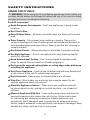
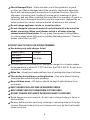
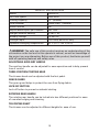
Operator’s Manual
18.0 Volt Cordless String Trimmer
Model No. 267-3333
IMPORTANT :
CHARGE BATTERY
BEFORE FIRST USE
WARNING! To reduce the risk of injury, user must read instruction manual.
Safety symbols in this manual are used to flag possible dangers. The safety symbols and their explanations require your full understanding. The safety
warnings do not, by themselves, eliminate any danger, nor are they substitute
for proper accident-prevention measures.
This Safety Alert Symbol indicates caution, warning, or danger. Failure to
obey a safety warning can result in serious injury to yourself or others. To reduce
the risk of injury, fire, or electric shock, always follow the safety precautions.
TABLE OF CONTENTS
Safety Symbols ..................................................................................page 3-4
Safety Instructions ............................................................................page 5-9
Description .........................................................................................page 9-10
Assembly ............................................................................................page 11
Operation ............................................................................................page 12-20
Maintenance ......................................................................................page 21-22
Troubleshooting .................................................................................page 22
Warranty .............................................................................................page 23
INTRODUCTION
SAVE THESE INSTRUCTIONS!
This Cordless String Trimmer has many features for making its use more pleasant
and enjoyable. Safety, performance, and dependability have been given top
priority in the design of this product making it easy to maintain and operate.
2
SAFETY SYMBOLS
The purpose of safety symbols is to attract your attention to possible
dangers. The safety symbols and the explanations with them deserve
your careful attention and understanding. The symbol warnings do not, by
themselves, eliminate any danger. The instructions and warnings they give
are no substitutes for proper accident prevention measures.
WARNING: Be sure to read and understand all safety instructions in this
manual, including all safety alert symbols such as “DANGER,” ”WARNING,”
and “CAUTION” before using this trimmer. Failure to following all instructions
listed below may result in electric shock, fire, and/or serious personal injury.
SYMBOL
SIGNAL
DANGER:
MEANING
Indicates an imminently hazardous situation,
which, if not avoided, will result in death or
serious injury.
WARNING:
Indicates a potentially hazardous situation, which,
if not avoided, could result in death or serious
injury.
CAUTION:
Indicates a potentially hazardous situation, which,
if not avoided, may result in minor or moderate
injury.
NOTE:
(Without Safety Alert Symbol) Indicates a situation
that may result in property damage.
WARNING: To ensure safety and reliability, all repairs should be performed
by a qualified service technician at Authorized Service Center.
WARNING: The operation of any power tool can result in
foreign objects being thrown into your eyes, which can result
in severe eye damage. Before beginning power tool operation,
always wear safety goggles or safety glasses with side shields
and a full-face shield when needed. We recommend a Wide
Vision Safety Mask for use over eyeglasses or standard safety
glasses with side shields. Always use eye protection which is
marked to comply with ANSI Z87.1
SAVE THESE INSTRUCTIONS
3
Some of these following symbols may be used on this tool. Please study them
and learn their meaning. Proper interpretation of these symbols will allow
you to operate the tool better and safer.
SYMBOL NAME
V
Volts
DESIGNATION/EXPLANATION
Voltage
A
Amperes
Current
Hz
Hertz
Frequency (cycles per second)
W
Watt
Power
min
Minutes
Time
Alternating Current
Type of current
Direct Current
Type or a characteristic of current
No Load Speed
Rotational speed, at no load
Class II
Construction
Double-insulated construction
Per Minute
Revolutions, strokes, surface speed, orbits etc., per minute
Wet Conditions
Alert
Do not expose to rain or use in damp locations.
Read The
Operator’s Manual
To reduce the risk of injury, user must read operator’s
manual.
Eye Protection
Always wear safety goggles or safety glasses with side
shields, or a full face shield when operating this product.
Safety Alert
Precautions that involve your safety.
No Hands Symbol
Failure to keep your hands away from the blade will result in
serious personal injury.
No Hands Symbol
Failure to keep your hands away from the blade will result in
serious personal injury.
No Hands Symbol
Failure to keep your hands away from the blade will result in
serious personal injury.
No Hands Symbol
Failure to keep your hands away from the blade will result in
serious personal injury.
Hot Surface
To reduce the risk of injury or damage, avoid contact with
any hot surface.
no
.../min
.../min
.../min
.../min
.../min
.../min
.../min
.../min
.../min
.../min
.../min
.../min
4
SAFETY INSTRUCTIONS
GENRAL SAFETY RULES
WARNING! When using electric gardening appliances, basic safety precautions should always be followed to reduce the risk of fire, electric shock,
and personal injury, including the following.
Read All Instructions!
void Dangerous Environments – Don’t use appliances in damp or wet
A
locations.
Don’t Use In Rain.
eep Children Away – All visitors should be kept at a distance from work
K
area.
ress Properly – Do not wear loose clothing or jewelry. They can be
D
caught in moving parts. Use of rubber gloves and substantial footwear is
recommended when working outdoors. Wear protective hair covering to
contain long hair.
Use Safety Glasses – Always use face or dust mask if operation is dusty.
se Right Appliance – Do not use appliance for any job except that for
U
which it is intended.
void Unintentional Starting – Don’t carry plugged-in appliance with
A
finger on switch. Be sure switch is off when plugging in.
on’t grasp the exposed cutting blades or cutting edges when picking up
D
or holding the appliance.
on’t Force Appliance – It will do the job better and with less likelihood of
D
a risk of injury at the rate for which it was designed.
Don’t Overreach – Keep proper footing and balance at all times.
tay Alert – Watch what you are doing. Use common sense. Do not
S
operate appliance when you are tired.
tore Idle Appliances Indoors – When not in use, appliances should
S
be stored indoors in dry, and high or locked-up place – out of reach of
children.
aintain Appliance With Care – Keep cutting edge sharp and clean for
M
best performance and to reduce the risk of injury. Follow instructions
for lubricating and changing accessories. Inspect appliance cord
periodically, and if damaged, have it repaired by an authorized service
facility. Inspect extension cords periodically and replace if damaged. Keep
handles dry, clean, and free from oil and grease.
5
heck Damaged Parts – Before further use of the appliance, a guard
C
or other part that is damaged should be carefully checked to determine
that it will operate properly and perform its intended function. Check for
alignment of moving parts, binding of moving parts, breakage of parts,
mounting, and any other condition that may affect its operation. A guard or
other part that is damaged should be properly repaired or replaced by an
authorized service center unless indicated elsewhere in this manual.
Do not charge appliance in rain, or in wet locations.
o not attempt to remove cut material nor hold material to be cut when
D
blades are moving. Make sure trimmer switch is off when clearing
jammed material from blades. Do not grasp the exposed cutting blades
or cutting edges when picking up or holding the hedge trimmer. “Caution–
blades coast after turn off.”
SPECIFIC SAFETY RULES FOR STRING TRIMMER
Use battery only with charger listed.
Battery pack
252-8024
252-8028
252-8032
Charger
252-8036
F or best results, your battery tool should be charged in a location where
the temperature is above 41°F (5°C) but less that 122°F (50°C). Do not store
outside or in vehicles.
Nylon line – Keep face, hands and feet clear of rotating nylon line at all times.
T he rotating line performs a cutting function – Use care when trimming
around screens and desirable plantings.
eep children away – All visitors should be kept at safe distance from
K
work area.
KEEP GUARDS IN PLACE AND IN WORKING ORDER.
KEEP HANDS AND FEET AWAYFROM CUTTING AREA.
DO NOT CHARGE APPLIANCE IN RAIN OR IN WET LOCATIONS.
void dangerous environments- Do not use or charge battery in damp or
A
wet locations.
emove battery before servicing, cleaning or removing material from the
R
trimmer. Remove battery from your trimmer and carry by the front handle
when not in use.
6
E xercise care in handling batteries in order not to short the battery with
conducting materials such as rings, bracelets and keys. The battery or
conductor may overheat and cause burns.
o not open or mutilate the batteries. Released electrolyte is corrosive
D
and may cause damage to the eyes or skin. It may be toxic if swallowed.
WARNING! Use the attachment and accessory recommended by the
manufacturer. Use any other accessory or attachment may increase the risk
of injury.
I mportant WARNING!– When being used as an edger, stones, pieces of
metal and other objects can be thrown out at high speed by the line. The
unit and guard are designed to reduce the danger. However, the following
special precautions should be taken:
WARNING! Make sure that other persons and pets are at least 100 ft.
(30.5m) away.
WARNING! To reduce the risk of rebound (ricochet) injury, work going
away from any nearby solid object such as a wall, steps, large stone, tree, etc.
Use great care when working close to solid objects, and, where necessary, do
edging or trimming by hand.
SAFETY RULES FOR CHARGER
WARNING! Read and understand all instructions. Failure to follow all instructions listed below may result in electric shock, fire, and/or serious personal injury.
efore using the battery charger, read all instructions and cautionary
B
markings in this manual and on the battery charger, the battery, and the
product using the battery to prevent misuse of the products and possible
injury or damage.
CAUTION! To reduce the risk of electric shock or damage to the charger
and battery, charge only those rechargeable batteries specifically designated
on your charger’s label. Other types of batteries may burst, causing personal
injury or damage.
o not use the charger outdoors or expose it to wet or damp conditions.
D
Water entering the charger will increase the risk of electric shock.
se of an attachment not recommended or sold by the battery-charger
U
manufacturer may result in a risk of fire, electric shock or injury to persons.
o not abuse the cord or charger. Never use the cord to carry the charger.
D
Do not pull the charger cord to disconnect the plug from receptacle.
Damage to the cord or charger could occur and create an electric shock
hazard. Replace damaged cords immediately.
7
ake sure that the cord is located so that it will not be stepped on, tripped
M
over, come in contact with sharp edges or moving parts, or otherwise
subjected to damage or stress. This will reduce the risk of accidental falls,
which could cause injury and damage to the cord, which could then result
in electric shock.
eep the cord and charger from heat to prevent damage to the housing or
K
internal parts.
o not allow gasoline, oils, petroleum-based products, etc. to come in
D
contact with plastic parts. These materials contain chemicals that can
damage, weaken,or destroy plastic.
n extension cord should not be used unless absolutely necessary. Use of
A
an improper extension cord could result in a risk of fire and electric shock.
If an extension cord must be used, make sure that:
The pins on plug of extension cord are the same number, size and shape
as those of the plug on charger.
The cord is properly wired and in good electrical condition
The size is large enough for AC ampere rating of charger as specified below:
The Cord Length (Feet)
25’ 50’ 100’
Cord Size (AWG)
16 16 16
NOTE: AWG = American Wire Gauge
o not operate the charger with a damaged cord or plug, which could
D
cause shorting and electric shock. If damaged, have the charger repaired
or replaced by an authorized service technician at Service Center.
o not operate the charger if it has received a sharp blow, been dropped,
D
or has otherwise been damaged in any way. Take it to an authorized
service technician at Authorized Service Center for an electrical check to
determine if the charger is in good working order.
o not disassemble the charger. Take it to an authorized service technician
D
at an Authorized Service Center when service or repair is required.
Incorrect reassembly may result in a risk of electric shock or fire.
T o reduce the risk of electric shock, unplug the charger from the electrical
outlet before attempting any maintenance or cleaning to reduce the risk of
electric shock.
isconnect charger from the power supply when not in use. This will
D
reduce the risk of electric shock or damage to the charger if metal items
should fall into the opening. It will also help prevent damage to the
charger during a power surge.
isk of electric shock. Do not touch the uninsulated portion of output
R
connector or uninsulated battery terminal.
8
ave these instructions. Refer to them frequently and use them to instruct
S
others who may use this tool. If you lend this tool to someone else, also
lend these instructions to them to prevent misuse of the product and
possible injury.
DESCRIPTION
KNOW THE STRING TRIMMER (Fig.1)
Before attempting to use this trimmer, become familiar with all of its
operating features and safety requirements.
Fig. 1
Battery pack
release button
Lock-off button
Battery pack
Trigger switch
Auxiliary handle
Auxiliary handle
locking knob
Lock collar
Telescoping shaft
Foot pedal
Wire edge
guide
Grass guard
Line spool cover
9
PRODUCT SPECIFICATIONS
Motor
18Volt DC
No Load Speed
9000 RPM
Cutting capacity
12” (305mm)
Line diameter
Twist 0.065” (1.65mm)
Shaft rotation
90o
Replacement spool part number
267-3334
Weight (without battery)
4 LBS 1 OZ
Battery Voltage
18 Volt DC
Charger Input
120-Volts, 60 Hz AC only
Optimum Charging Temperature
41°F (5°C) -122°F (50°C)
WARNING! The safe use of this product requires an understanding of the
information on the tool and in this operator’s manual, as well as knowledge of
the project you are attempting. Before use of this product, familiarize yourself
with all operating features and safety rules.
ADJUSTABLE AUXILIARY HANDLE
The auxiliary handle can be adjusted for ease operation and to help prevent
loss of control.
THREE-POSITION PIVOTING HEAD
The trimmer head can be adjusted with the foot pedal.
GRASS GUARD
The grass guard helps to protect the user from flying debris.
LOCK-OFF BUTTON
Lock-off button to prevent accidental starting.
ROTATING REAR HANDLE
The rotating rear handle can be locked into two different positions for ease
of use when edging and trimming.
TELECOPING SHAFT
The trimmer can be adjusted to different heights for ease of use.
10
ASSEMBLY
WARNING! If any part is broken or missing, do not attempt to attach the
battery or operate the String Trimmer until the broken or missing part is replaced. Failure to do so could result in possible serious injury.
WARNING! Do not attempt to modify this tool or create accessories not
recommended for use with this String Trimmer. Any such alteration or modification is misuse and could result in a hazardous condition leading to possible
serious injury.
WARNING! To prevent accidental starting that could cause serious personal injury, always remove the battery pack from the String Trimmer when
assembling parts.
UNPACKING
This product requires assembly.
arefully remove the tool and any accessories from the box. Make sure
C
that all items listed in the packing list are included.
I nspect the tool carefully to make sure no breakage or damage occurred
during shipping.
o not discard the packing material until you have carefully inspected and
D
satisfactorily operated the tool.
PACKING LIST
String Trimmer, Grass guard, 2PCS screw for grass guide, Wire edge guide,
Lithium-ion battery, Charger and Operator’s manual.
11
OPERATION
POWER INDICATOR (Fig.2)
Fig. 2
80-100%
Charge
60-79%
Charge
40-59%
Charge
20-39%
Charge
Under 20%
Charge
High/low
temperature
This Li-ion battery pack is equipped with a power indicator, which is used
to display the battery pack remaining run time. Press the power indicator
button to display the LED lights. The LED lights will stay lit for approximately 4
seconds.
NOTE: The power indicator can be used whether the battery is attached or
removed from tool.
LOW CAPACITY WARNING
If one LED on the power indicator begins to flash, the battery pack’s charge is
under 20% capacity and should be recharged.
Unlike other battery pack types, Lithium-Ion battery packs deliver fade-free
power for their entire run time. The tool will not experience a slow, gradual
loss of power as you work. To signal that the battery pack is at the end of
its run time and needs to be charged, power to the tool will drop quickly.
The power indicator will begin to display four flashing LED lights when it
is completely discharged. When this happens, remove the tool from the
workpiece and charge the battery pack as needed.
BATTERY PROTECTION
To protect the battery from damage and prolong its life, the battery pack
circuitry will turn off the battery pack if it becomes overloaded or if the
temperature becomes too high during use. This may happen in extremely
high torque, binding and stalling situations. The battery pack will begin
normal operation when it cools down.
12
The power indicator will display four flashing LED lights if the circuitry
detects a momentary overload. You can conveniently reset the battery pack
by releasing the power-tool trigger. Press the power indicator button again to
display the remaining charge.
NOTE: If the power indicator continues to flash four LED lights after resetting,
place the battery pack on the charger to evaluate the battery condition.
NOTE: A significantly reduced run time after fully charging the battery pack
indicates that the battery is near the end of its usable life and must be replaced.
COLD WEATHER OPERATION
When the battery pack is very cold, it may “pulse” for the first minute of
use to warm itself. Put the battery pack on a tool and use the tool in a light
application. After about a minute, the battery pack will have warmed itself
and will operate normally.
WHEN TO CHARGE THE BATTERY PACK
The Lithium-Ion battery can be charged at any time and will not develop a
“memory” when charged after only a partial discharge. It is not necessary
to run down the battery pack charge before recharging. Remove the battery
pack from the tool when convenient for you and your job.
se the power indicator to determine when you need to recharge the
U
battery pack.
Y ou can “top-off” your battery pack’s charge before starting a big job or a
long period of use.
ue to Lithium-Ion’s fade-free properties, the only time it is necessary to
D
charge the Lithium-Ion battery pack is when the pack has reached the
end of its charge. To signal the end of charge, power to the tool will drop
quickly. Charge the battery pack as needed.
HOW TO CHARGE THE BATTERY PACK
NOTE: This Lithium-Ion battery pack is shipped partially charged. Before
using it the first time, fully charge the battery pack.
A fully discharged battery pack will charge in about 75 minutes (for included
battery pack 252-8032) in a surrounding temperature between 41° F (5° C) and
122° F (50° C).
1. C
harge the battery pack with the correct charger.
2. C
onnect the charger to a power supply.
13
Model #:
3. A
ttach the battery pack to the
Fig. 3
charger by aligning the raised ribs
of the battery pack with the slot in
the charger. Slide the battery pack
onto the charger (Fig. 3)
252-8028
Li-ion
Use only
with charger
252-8036
.
4. T he Charger will communicate
with the battery pack’s circuitry
to evaluate the condition of the
battery pack.
5. D
uring normal charging, the green
LED on the charger will flash continuously.
6. A
fter charging is complete, the green LED on the charger will be on. The
power indicator LED lights will not be displayed when the power indicator
button is pressed while the battery pack is on the charger.
7. T he battery pack will fully charge, but will not overcharge, if left on the
Charger.
LED FUNCTIONS OF CHARGER (Fig. 4)
Fig. 4
BATTERY
PACK
RED
LED
GREEN
LED
Hot/cold
battery
On
Off
Fast charge will begin when
battery returns to 41°F (5°C)
and 122°F (50°C).
DEFECTIVE
BATTERY
Defective
Flashing
Off
Battery pack or charger
is defective.
BATTERY
CHARGING
Charging
Off
Flashing
BATTERY
FULL
Fully
charged
Off
On
LED INDICATOR
HI / LO TEMP.
ACTION
Charging
Charging is complete.
CHARGING A HOT BATTERY PACK
If the battery pack is above normal temperature range, the red LED will
illuminate and the green LED will be off. When the battery pack cools down
to approximately 122°F (50°C), the charger will automatically begin charging.
CHARGING A COLD BATTERY PACK
If the battery pack is below the normal temperature range, the red LED will
illuminate and the green LED will be off. When the battery warms to a temperature
of more than 41°F (5°C), the charger will automatically begin charging.
14
DEFECTIVE BATTERY
If the charger detects a problem, the red LED will begin flashing and the
green LED will be off.
1. I f registering as defective, remove and reinsert the battery pack in the
charger. If the LED status reads “defective” a second time, try charging a
different battery pack.
2. I f a different battery pack charges normally, dispose of the defective
battery pack (see Maintenance section).
3. I f a different battery pack also indicates “defective,” the charger may
be defective.
BATTERY CHARGING
If the battery pack is within normal temperature range, the green LED will
begin flashing and the red LED will be off. The battery pack will reach a
full charge in 75 minutes (for included battery pack 252-8032). The power
indicator LED lights will cycle from right to left during charging. This is part of
the normal charging operation.
BATTERY FULL
After fully charged, the green LED Light on the charger will be on and the red
LED light will be off.
NOTE: The battery pack will fully charge, but will not overcharge, if left on
the charger.
NOTE: The power indicator LED lights will not be displayed when the power
indicator button pressed while the battery pack is still on the charger.
NOTE: Charger may warm with several continuous charge cycles. This is part
of the normal operation of the charge. Charge in a well ventilated area.
TO ATTACH BATTERY PACK (Fig. 5)
1. L ock the trigger switch in the
“OFF” position.
Fig. 5
2. A
lign the raised portion on the
battery pack with the grooves on
the bottom of the trimmer, and
then attach the battery pack to
the trimmer as shown.
ATTACH
3. M
ake sure that the latch on the
battery pack snaps into place
and the battery pack is secured to
the trimmer before beginning operation.
15
TO DETACH BATTERY PACK (Fig. 5)
1. L ock the trigger switch in “OFF” position.
2. D
epress the battery release buttons located on the front of the battery
pack to release the battery pack.
3. P
ull forward on the battery pack to remove from the tool.
CAUTION: when placing battery pack on the tool, be sure that the raised
rib on battery pack aligns with the groove on the saw and the latches snap into
place properly. Improper assembly of the battery pack can cause damage to
internal components.
ATTACH THE GRASS GUARD (Fig.6)
WARNING! Never operate tool without guard firmly in place. The guard
must always be on the tool to protect the user.
1. R
emove the battery pack.
2. A
ssemble the guard over the lug on
the motor housing slide the guard
downward to lock on the lug.
Fig. 6
3. S
crew the preassembled screws
in the guard into the motor
housing.
AUXILIARY HANDLE ADJUSTMENT
(Fig.7)
Fig. 7
The angle of auxiliary handle can
be adjusted.
1. R
emove the battery pack.
2. S
et the trimmer on a flat surface
and turn the knob counterclockwise to loosen the handle.
3. A
djust the auxiliary handle to a
comfortable position for the user.
4. T urn the knob clockwise and until the handle is securely tightened before
reinstalling battery pack.
16
CUTTING HEIGHT ADJUSTMENT (Fig.8)
The overall height of the trimmer
can be adjusted.
Fig. 8
1. R
emove the battery pack.
2. P
ull the lock collar to loosen the
telescoping shaft.
3. T he telescoping shaft can then
be adjusted to be shorter or
longer. When the desired length
is achieved, push the lock collar
to tighten the telescoping shaft.
THREE-POSITION PIVOTING HEAD
(Fig.9)
Fig. 9
The trimmer head can be adjusted
to three different positions.
1. R
emove the battery pack.
2. D
epress the foot pedal and move
the trimmer head up or down
to one of the three positions
indicated by the notches.
NOTE: Adjust the trimmer head
to the first and second position
for trimming. Adjust to the third
position for edging and tilting
function.
3. M
ake sure the trimmer head
is securely locked into place
before reinstalling the battery
pack.
17
OPERATION
CAUTION: Always wear eye protection.
CAUTION: Inspect the area to be trimmed and remove any wires, cords, or
string-like objects which could become entangled in the rotating line or spool.
Be particularly careful to avoid any wire which might be bent outward into the
path of the tool, such as barbs at the base of a chain link fence.
1. T o turn trimmer on, depress the
lock-off button and squeeze the
trigger switch. To turn the tool
off, release the trigger, as shown
in Fig.10.
Fig. 10
2. S
lowly swing trimmer side-toside as shown in Figure 11.
3. F or maintenance edging mode,
loosen the lock collar and turn
the handle 90 degree counterclockwise, then tighten the lock
collar. Press the foot pedal to
lock the trimmer in the third
position (edge position). Rotate
the wire edge guide down into
place for the edging mode.
Fig. 11
4. T o operate as a maintenance
edger, position the trimmer as
shown in Figure 12.
5. T o return to trimming mode, turn
off the tool, and perform step 3 in
reverse order
Fig. 12
NOTE: For easy operation in edging
mode, pull the string trimmer
backward instead of pushing it
forward.
18
LINE FEEDING
Your trimmer uses 0.065” diameter twist nylon line to cut grass and weeds
quickly and easily.
Check the nylon line regularly.
When trimming performance decreases, adjust the line length. With the
trimmer running, bump the cutting head on the grass; the nylon line will
extend automatically. Any excess will be automatically cut to length.
REPLACING SPOOL/ CLEARING JAMS AND TANGLED LINES
From time to time, especially when cutting thick , the line feeding hub may
become clogged with sap or other material and the line will become jammed
as a result. To clear the jam, follow the steps listed below.
1. T urn off the trimmer and remove the battery.
2. P
ress the release tabs on the
line spool cover, as shown in
Figure 13 and remove the cover
by pulling it straight off.
Fig. 13
3. L ift the line spool out of the hub
and clear any broken line or
cutting debris from the spool
area.
4. I n case of jams and tangled
line, unwrap about one foot
(30cm) of line to ensure that it is
undamaged. If it is OK rewind it
and insert the line end through
the eyelet in the spool hub, as
shown in Figure 14.
Fig. 14
5. P
ress the spool down and
replace the spool cover,
ensuring that the release tabs
lock on both sides.
6. R
einstall the battery pack and
turn on the trimmer, adjusting
the line length to ensure that satisfactory cutting is maintained.
19
REWINDING SPOOL FROM BULK LINE (Use only 0.065” diameter line)
To install bulk line, follow the steps below.
1. T urn off the trimmer and remove the battery.
2. P
ress the release tabs on the line spool cover and remove the cover by
pulling it straight off.
3. R
emove the spool from the tool and remove and discard all line on the spool.
4. I nsert one end of the bulk line into the hole in the spool. Hold the line in the
hole and pull the rest of the line through the slot in the spool.
5. W
ind the bulk line onto the spool in the direction of the arrow on spool
until it is nearly full.
6. I nsert the line end through the eyelet in the spool hub. Press the spool down
and relocate the spool cover, ensure the release tabs lock on both sides.
7. R
einstall battery pack and turn on the trimmer, adjusting the line length to
ensure that satisfactory cutting is maintained.
20
MAINTENANCE
CAUTION! Before performing maintenance or cleaning, remove the battery pack from the trimmer.
1. T he tool may be cleaned most effectively with compressed dry air. Always
wear safety goggles when cleaning tools with compressed air.
2. A
void using solvents when cleaning plastic parts. Most plastics are
susceptible to damage from various types of commercial solvents. Use
clean cloths to remove dirt, dust, oil, grease, etc.
BATTERIES:
The battery pack is equipped with Lithium-Ion rechargeable batteries. The
duration of use from each charge will depend on the type of work performed.
The batteries in this tool have been designed to provide maximum troublefree life. Like all batteries, they will eventually wear out. Do not disassemble
the battery pack or attempt to replace the batteries. Handling of the batteries,
especially when wearing rings and jewelry could result in a serious burn.
To obtain the longest possible battery life, read and understand the
operator’s manual.
I t is good practice to unplug the Charger/Adapter and remove the LithiumIon battery pack when not in use.
For Lithium-Ion battery pack storage longer than 30 days:
tore the Lithium-Ion battery pack where the temperature is below 80°F
S
(26°C) and free of moisture.
Store Lithium-Ion battery packs in a 30%-50% charged condition.
Every six months of storage, fully charge the Lithium-Ion battery pack.
Exterior may be cleaned with a cloth or soft non-metallic brush.
BATTERY PACK REMOVAL AND PREPARATION FOR RECYCLING
To preserve natural resources, please recycle or dispose
of batteries properly. This product contains lithium-ion
batteries. Local, state, or federal laws may prohibit disposal
of lithium-ion batteries in ordinary trash. Consult your
local waste authority for information regarding available
recycling and/or disposal options.
21
WARNING! Upon removal of the battery pack for disposal or recycling,
cover the battery pack’s terminals with heavy-duty adhesive tape. Do not attempt to destroy or disassemble battery pack or remove any of its components.
Lithium-Ion batteries must be recycled or disposed of properly. Also, never
touch both terminals with metal objects and/or body parts as short circuit may
result. Keep away from children. Failure to comply with these warnings could
result in fire and/or serious injury.
TROUBLESHOOTING
PROBLEM
CAUSE OF THE PROBLEM
Line won’t feed
Not enough line on spool
Line tangled in spool
Line fails to cut off
Unit will not start
Line cutter in guard is
damaged or missing
Battery not installed
properly
Battery not charged
22
SUGGESTED
CORRECTIVE ACTION
Replace spool or rewind
with new line
Unwrap and rewind the
line
Return to service center
for repair
Check battery installation
Check battery charging
requirements
WARRANTY
3-MONTH MONEY BACK GUARANTEE:
This MASTERFORCE™ brand power tool carries our 3-Month Money Back
Guarantee. If you are not completely satisfied with your MASTERFORCE™
brand power tool for any reason within three (3) months from the date of
purchase, return the tool with your original receipt to any
retail
store, and we will provide you a refund – no questions asked.
3-YEAR LIMITED WARRANTY:
This MASTERFORCE™ brand power tool carries our famous No Hassle
3-Year Limited Warranty to the original purchaser. If the tool fails within
three (3) years from the date of purchase, simply bring this tool and its sale
receipt back to your nearest
retail store for a free equivalent
replacement within those three years. Notwithstanding the foregoing, this
limited warranty does not cover any damage that has resulted from abuse or
misuse of the Merchandise. This warranty: (1) excludes expendable parts
including but not limited to blades, belts, bits, light bulbs, and/or batteries;
(2) shall be void if this tool is used for commercial and/or rental purposes;
and (3) does not cover any losses, injuries to persons/property or costs. This
warranty does give you specific legal rights and you may have other rights,
which vary from state to state. Be careful, tools are dangerous if improperly
used or maintained. Seller’s employees are not qualified to advise you on
the use of this Merchandise. Any oral representation(s) made will not be
binding on seller or its employees. The rights under this limited warranty
are to the original purchaser of the Merchandise and may not be transferred
to any subsequent owner. This limited warranty is in lieu of all warranties,
expressed or implied including warranties or merchantability and fitness for
a particular purpose. Seller shall not be liable for any special, incidental, or
consequential damages. The sole exclusive remedy against the seller will be
for the replacement of any defects as provided herein, as long as the seller
is willing or able to replace this product or is willing to refund the purchase
price as provided above. For insurance purposes, seller is not allowed to
demonstrate any of these power tools for you.
For questions / comments, technical assistance or repair parts –
Please Call Toll Free at: 1-866-917-4374 (M-F 8am – 6pm)
SAVE YOUR RECEIPTS. THIS WARRANTY IS VOID WITHOUT THEM.
23
24