1
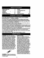
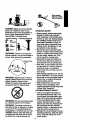
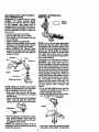
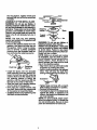
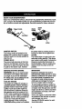
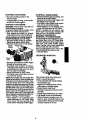
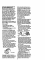
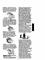
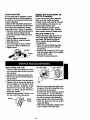
Operator's Manual
®
CRRFTZMRN
32cc 2-Cycle Engine
17 Inch Cutting Path / .080 In. Line
GASOLINE
BRUSHWACKER ®
Model No.
358.795050
Read and follow all Safety Rules and Operating
DANGER:
Instructions before first use of this product.
I_
•
For
to Your
questions
about
this product:
Call answers
7 am-7 pm,
Mon--Sat;
Sun,
10 am-7
pm
1-800-235-5878
(.o,,_.,,=._._o.._.)
Se_IYs,Roebuck and Co., Hoffman Estates, IL 60179 USA
530-087633
08/17/98
Warranty Statement
Safety Rules
Assembly
Operation
Maintenance
Sewice & Adjustments
2
_
.....
Storage
15
2
5
8
12
Troubleshooting Chart
Parts List
16
20
Spanish
23
13
Parts and Ordering
Back
FULL ONE YEAR WARRANTY ON CRAFTSMAN GAS POWERED
BRUSHWACKER
® BLADED TRIMMER.
For one year from the date of purchase, when this Craftsman Gas Powered
Brushwacker is maintained, lubricated and tuned up accordingto the operating
and maintenance instructionsin the Operator's Manual, Sears will repair, free of
charge, any defect in materials or workmanship.
This warranty excludes the blade, nylon line, spark plug, and air filter, which are
expendable parts and become wom duringnormal use.
If this Brushwacker is used for commercial purposes, this warranty applies for only
90 days from the date of purchase. If this Brushwacker is used for rental purposes,
this warranty applies for only30 days from the date of purchase. This warranty applies only while this product is in use in the United States.
WARRANTY SERVICE IS AVAILABLE BY RETURNING THE BRUSHWACKER
TO THE NEAREST SEARS SERVICE CENTER IN THE UNITED STATES.
This warranty gives you specific legal rights,and you may also have other rights
which vary from state to state.
Sears, Roebuck and Co., D/817 WA Hoffman Estates, IL 60179
SAFETY
DANGER: This power tool can be
dangerous! This unit can cause serious
injuryincludingamputationor blindness
to the operatorand others. The warnings and safety instructionsin this manual must be followedto providemasonable safety and efficiencyin usingthe
unit.3"beeperator is responsiblefor followingthe wamings and instructionsin
this manualand on the unit.Read the
entire Operator'sManual before assernbling and usingthe unit! Restrictthe use
of this unitto persons who read, understand, and followthe warningsand instructions in this manual and on the unit.
Never allowchildrento use this uniL
NOTICE
Exposure to vibrations through prolonged use of gasoline powered hand
tools could cause blood vessel or
nerve damage in the fingers, hands,
and joints of people prone to circulation disorders or abnormal swellings.
Prolonged use in cold weather has
been linked to blood vessel damage in
otherwise healthy people. If symptoms
occur such as numbness, pain, lose of
strength, change in skin color or texture, or loss of feeling in the fingers,
hands or joints, discontinue the use of
this tool and seek medical attention.
An anti-vibration system does not
guarantee the avoidance of these
problems. Users who operate power
tools on a continual and regular basis
must monitor closely their physical
condition and the condition of this tool.
WARNII_G:
Follow all wamings and
instructions. Failure to do so can result
in sedous injury.
2
tiSt_ coas_ng
• by contact
with cut material
®
DANGER: Bladecanthrustviolently
awayfrommaterialit doesnot cut.
Bladethrustcan cause amputation of
OPERATOR SAFETY
• Dress properly. Always wear safety
glasses or similar eye protection
when operating, or performing maintenance on your unR. (Safety glasses
are available.) Always wear face or
dust mask if operation is dusty. Always wear heavy, long pants, long
sleeves, boots, and gloves. Do not
go barefoot or wear sanda/s.
• Secure hair above shoulder length.
Secure or remove loose clothing and
jewelry or clothing with loosely hanging ties, straps, tassels, etc. They
can be caught in moving parts.
• Being fully covered also helps protect you from debris and pieces of
toxic plants thrown by spinning line.
• Stay Alert. Do not operate unit when
you are tired, ill, or under influence
of alcohol, drugs, or medication.
Watch what you are doing; usa common sense.
• Wear hearing protection if you use the
unit for more than 1-1/2 hours per day.
• Never start or run the engine inside a
closed room or building. Breathing
exhaust fumes can kill.
arms or legs. Keep people and animals 50 feet (15 meters) away.
ALWAYS WEAR
I
Guards
Leg
IJ
U BootaI
WARNING:
•
Trimmer line can throw
objects violently. You can be blinded or
injured. Wear eye and leg protection.
HazardZone
WARNING:
Hazard zone for thrown
objects. Blade/Trimmer line can throw
objects violently. Others can be
blinded or injured. Keep people and
animals 50 feet (15 meters) away.
WARNING:
• Keep handles free of oil and fuel.
• Always usa the handlebar and a
properly adjusted shoulder strap with
a blade. See "Assembly."
UNIT/MAINTENANCE
SAFETY
• Look for and replace damaged or
loose parts before each usa. Look
for and repair fuel leaks before usa.
Keep unit in good working condition.
• Throw away blades that are bent,
warped, cracked, broken, or damaged in any other way. Replace trimmer head parts that are cracked,
chipped, broken, or damaged in any
other way before using the unit.
• Maintain the unit according to recommended procedures. Keep the blade
sharp. Keep the cutting line at the
proper length.
Do not use trimmer head
as a fastening device for the blade.
WARNING:
The blade continues to
spin after throttle is released or, engine
is turned off. The coasting blade can
throw obiects or seriously cut you if acciden-fft-ally
touched. Stop the blade by
contacting the left hand side of coasting blade with material already cut.
3
• Use only .080" (2.4 ram) diameter
Craftsman © brand line. Never use
wire, rope, stdng, etc.
• Install required shield properly before
using the uniL Use the metal shield
for all metal blade use. Usethe plastic shield for all line trimmer-use.
- • Use only specified blade or tdmmer
head; make sure it is properly installed and securely fastened,
* Never start engine with clutch shroud
removed. The clutch can fly off and
cause serious injury.
• Be sure blade or tdmmer head stops
turning when engine idles,
• Disconnect the spark plug before
performing maintenance (except carburetor adjustments).
• Make carburetor adjustments with
the lower end supported to prevent
the blade or trimmer line from contacting any object. Hold the unit by
hand; do not use the shoulder strap
for support.
• Keep others away when making carburetor adjustments.
• Use only recommended Craftsman
accessories and replacement parts.
• Have all maintenance and service
not explained in this manual performed by a Sears Service_Center.
FUEL SAFETY
•
•
•
•
•
•
•
•
Mix and pour fuel outdoors.
Keep away from sparks or flames.
Use a container approved for fuel.
Do not smoke or allow smoking near
fuel or the unit or while using the unit.
Wipe up all fuel spills before starting
engine.
Moye,r_at-least 10 feet (3 meters) away
from fueling site before starling engine.
Stop engine and allow-it to-cool before removing fuel cap.
Empty the fuel tank before storing
the unit. Use up fuel left in the carburetor by starting the engine and letting it run until it stops.
• Store unitand fuel in an area where
fuel vaporscannot reach sparksor
open flames from water heaters,electric motorsor switches,furnaces, etc.
CUTTING SAFETY
• Inspectthe area to be cut before
each use. Remove objects (rocks,
broken glass, nails, wire, string, etc.)
which can be thrown or become entangled in the blade or trimmer head.
• Keep others includingchildren, animals, bystanders,and helpers at
least 50 feet (15 meters) away. Stop
the engine immediately if you are approached.
• Always keep engine on the righthand side of your body.
• Hold the unitfirmly with both hands.
• Keep firm footing and balance. Do
not overreach.
• Keep blade or trimmer head below
waist level.
• Do not raise engineabove your waist.
• Keep all pads of your body away
from blade, trimmer head, and muffler when engine is running.
• Cut from your rightto your left.
• Use onlyfor jobs explained in this
manual.
TRANSPORTING AND STORAGE
• Stop the unitbefore carrying.
• Keep muffler away from your body.
• Allow engine to cool and secure unit
before storing ortransportingit in a
vehicle.
• Empty the fuel tank before storing or
transportingthe unit. Use up fuel left
in the carburetor by startingthe engine and letting it run untilit stops.
• Store unit and fuel in an area where
fuel vapors cannot roachsparks or
open flames from water heaters,
electdc motors or switches,fumaces,
etc.
• Store unit so the blade or line limiter
cannot accidentallycause injury.The
unitcan be hung by the tube.
• Store unit out of reach of children.
4
CARTON
CONTENTS
Check carton contents against the following list.
_
.....
Model: 358,795050
• Brushcutter
•
•
•
•
•
•
•
•
•
Handlebar screws (2)
Blade shield screws (4)
Cupped washer
Large nut for installing blade
Long hex wrench
Short hex wrench
Bracket cover
Metal shield
Plastic shield
•
•
•
•
•
Shoulder strap with waming
Weed blade
Trimmer head
Handlebar
Container of oil
Examine parts for damage.
damaged parts.
Do not use
NOTE: If you need assistance or find
that parts are missing or damaged, call
1-800-235-5878,
It is normal for the fuel filter to rattle in the
empty fuel tank.
Finding fuel or oil residue on muffler is
normal due to carburetor adjustments
and testing done by the manufacturer.
ASSEMBLY
WARNING:
If received assembled, re_.ata
tatata_all
steps to ensure your unit is propermbled and all fastenem are secure.
TOOLS
REQUIRED
ASSEMBLY
WARNING:
OF SHOULDER
STRAP
engineare required.
• Insert'
the
on your left
Make sure the
danger sign is on your back and the
hook is to the right side of your waist.
NOTE: A one-half twist is built in the
shoulder strap to allow the strap to rest
flat on the shoulder.
• Adjust the strap, allowing the hook to
be about 6 inches below the waist.
• Fasten the strap hook to the clamp located between the foam grip and the
mounting block and lift the tool to the
operating position.
CONFIGURING
YOUR UNIT
You can configure your unit using a cutting head for grass and light weeds, or a
weed blade for cutting grass, weeds,
and brush up to 1/2 inch in diameter. To
assemble your unit, go to the section for
the desired configuration and follow the
instructions.
ASSEMBLY INFORMATION
- TRIMMER HEAD
adjustable
wrench
or large pliers
2 hex wrenches
(provided)
phmips screwdriver
ATTACHING
THE HANDLEBAR
)
DANGER: The barrier portion of the
handlebar must be installed as shown to
provide a barrier between operator and
the spinning blade.
• Locate the decal on the handlebar.
This decal includes two arrows. Position the handlebar on the mounting
bracket between these arrows.
• Position the bracket cover over the
handlebar. Again make sure the handlebar is between the arrows.
*, I_,_rt-screws and hand tighten only.
Be sure the handlebar is installed correctly; then, tighten each screw securely with the short hex wrench.
HEAD
TRIMMER
NOTE: If your unit has been assembled
for weed blade use, refer to the section
=ASSEMBLY INFORMATIONFOR USING
YOUR UNITWITHAWEEDBLADE"and reverse the steps to remove the metal
shield and blade before you mount the
plastic shield and trimmer head.
5
ATTACHINGTHE PLASTICSHIELD
ASSEMBLY INFORMATION ANDTRIMMERHEAD
WEED BLADE
WARNING:Theshieldmustbeproperly
installed.The shield provides partial
pmtsctionfromthe riskof thrown objects
BLADE
WEED
to _
operator and others and is
equil_3edwitha linelirnltdr whichct_sexcass linetotheproper length.The linelim- iter (on undersideof shield) is sharp and
can cut you.
Remove
wing nut
shield.
Insert bracket
intofrom
slot on
shield.
• Pivot shield until bolt passes through
hole in bracket.
Tighten the wing nut securely.
If your unithas a plasticcover over the
threads on the threaded shaft, remove
the covetingto expose the threads.
• Before installing the trimmer head,
make sure the dust cup and retaining
washer are positionedon the gearbox
as shown below.
Bracket _
RotainiDnU_er
.
c__
/
_
NOTE: Make sure all parts are propedy
installed as illustrated in the illustration
before installingthe trimmer head.
• Alignhole in the dust cup withthe hole
in the side of the gearbox by rotating
thd _st cup.
• Inserta small screwdriver intoaligned
holes. Th_ will keep-the'shaft from
tuming wholetighteningtrimmer head.
NOTE: If your unit has been assembled
for _mmer head use, refer to the section
"ATTACHING THE PLASTIC SHIELD AND
TRIMMER HEAD" and reverse the steps to
remove the plastic shield and trimmer
head before you mount the metal shield
and blade. Store these pads for future
use. Never use the trimmer head with the
metal blade installed.
ASSEMBLY OF THE METAL SHIELD
DANGER: The metal shield must be
properiyinstalled on the tool anytime the
tool is used with the blade. The forward
top of the metal shield helps to reduce
the occurrence of blade thrust which can
cause serious injury such as amputation
to the operator or bystanders. Failure to
install the shield in the position shown
can result in serious injury to the operator. The length of the shield must be
aligned with the length of the tube. The
blade is sharp and can cut you. Be sure
to wear gloves while working with
blades.
• If your unit has a plastic cover over the
threads on the shaft, remove the covering to expose the threads.
• Place the metal shield under the gearbox, and align the screw holes.
Shield_J,
Gearb°x
Screwdriver
• While holdingthe screwdriver in position, thread trimmer head onto the
shaft in the directionshown onthe de.qal_T_jbtenuntil secure.
NOTE:The ratainin(j washer must be
positionedwiththe ra0sedsectionfacing
toward the gearbox.
• Insertthe 4 mountingscrews through
the bottom of the shield. Thread them
6
into the gearbox. Tighten evenly and
securely with one of the hex wrenches
provided.
ASSEMBLY OF THE METAL BLADE
WARNING: Do not use any blades, or
fasteninghardware offie"thanthewashers and nutsillustratedin the followingil.
lustrations.These partsmustbe provided
by Sears, and installedas shown below.
Failureto use properpartscan cause the
blade to fly off and seriouslyhurt you or
others.
NOTE: The dust cup and retaining
washer are located on the gearbox and
not in the parts bag.
• Remove the retainer washer from the
gearbox, and leave the dust cup on
the gearbox. Note: It may be necessary to remove a plastic protective
covering from the threaded shaft before removingthe retaining washer.
Shield''_
Dust Cup/" _
ThreadedShaft
m
Retaining
_
Washer--__
_'_
Blade
WARNINGi Do not use any blades, or
fasteninghardwareotherthanthe
washersand nutsillustrated.These parts
must be providedby Seam, and installed
as shown below. Failure to use proper
partscancause thebladeto tiy offand seriouslyhurtyou or others.
NOTE: Make sure all parts are in place
as illustrated, and the blade is sandwiched between thedustcup and the retaining washer. There should be no
space between the blade and the dust
cup or the retainingwasher.
Dust Cup (_='_
WasherRetaining i of
gearboxinby
rotatingthe
blade.
Alignhole
dustcup
with hole
in side
Inserta small screwdriverintoaligned
• Install the blade over the threaded
holes. This will keep the shaft from
shaft extending from the gearbox betuming while tighteningthe blade nut.
tween the dust cup and the retaining
washer. Make sure the raised part of
the retaining washer is facing the
gearbox, and the raised area fits into
Scre__
the hole in the center of the blade.
• Slide the blade and retaining washer
onto the shaft of the gearbox.
• Now place the cupped washer onto
the shaft. Make sure the cupped side
of the washer is toward the blade.
• Installthe blade nut b_/ti_ghtening
onto
th'e'_haftcounterolockwJse.
Tightenblade nut firmlywith a wrench
i while holding screwdnver in position.
Remove the screwdriver.
• Turn blade by hand. Ifthe blade binds
against the shield, or appears to be
uneven, the blade isnot centered, and
you must reinstall.
NOTE: To remove blade, insert screwddver into aligned holes. Un-thread the
nut and remove parts. Be sure to store
parts and instructionsfor future use.
7
KNOW YOUR BRUSHWACKER
READ THIS OPERATOR'S MANUAL AND SAFETY RULES BEFORE OPERATING YOUR
UNIT. Compare the illustmtionswith your unit to familiarize yourself with the location of various controls and adjustments. Save this manual for future reference.
Trigger Handle
Starter
Pdrner
Bulb
Handlebar
Muffler
ON/STOP
SWITCH
The On/Stop switch is located on the
engine and is used to stop the engine.
Push the switch to the stop position to
stop the unit•
PRIMER BULB
The primer bulb removes air from the
fuel lines and fills them with fuel. This
allows you to start the engine with fewer pulls on the starter rope. Activate
BEFORE STARTING ENGINE
WARNING: Be sure to read the fuel
informationin the safety rules before
you begin. Ifyou do not understand
the safety rules, do not attempt to fuel
• yourIJi'_t._,all 1-800-235-5878.
FUELING ENGINE
This engine is certified to operate on
unleaded gasoline. Before operation,
gasoline must be mixed with a good
quality2-cycle air-cooled engine oil.
We recommend Craftsman brand oil.
Mix gasoline and oil at a ratio of 40:1
(A 40:1 ratio is obtained by mixing3.2
ounces of oil with I gallon of unleaded
gasoline). DO NOTUSE automotive oil
or boat oil. These oils will cause
engine damage. When mixingfuel,
foliow']f_]'mctions printed on container.
the primer bulb by pressing it and allowing it to retum to its original form.
CHOKE
The choke helps to supply fuel to the
carburetor during starting. This allows
you to start a cold engine. Activate the
choke by moving the choke lever to
the Full position. After the engine has
started, move the choke to the Off
position.
IMPORTANT
Experience indicates that alcohol
blended fuels (called gasohol or using
ethanol or methanol) can attract moisturs which leads to separation and
formationof acids duringstorage.
Acidicgas can damage the fuel systam of an engine while in storage.
To avoid engine problems, empty the
fuel system before storage for 30 days
or longer.Drain the gas tank, start the
engine and let it run untilthe fuel lines
and carburetor are empty. Use fresh
fuel next season.
Never use engine or carburetor cleaner products in the fuel tank or permanent damage may occur.
See the STORAGE section for addi-
tional information.
STOPPING
YOUR ENGINE
• Move the On/Stop switch to the
STOP position.
• If engine does not stop, move choke
to the Full Choke position.
STARTING
YOUR Ei_GINI="
WARNING:
The trimmer head will turn
"-
while starling the engine.
Avoid any contact with the muffler. A hoz
muffler can cause serious bums.
• Rest engine and shield on ground,
supporting tdmmer head off ground.
COLD ENGINE OR WARM ENGINE
AFTER RUNNING OUT OF FUEL
• Move the switch to the On position.
• Slowly press pdmer bulb 6 times..
• Move the choke lever to Full ChoKe.
Starter
Pdmer BulbA
Handle
_ ._-_1_
STARTING A WARM ENGINE
• Movetheswitchtotheonposition,
and
choke lever to Half Choke.
• Squeeze and hold throttle trigger until
the engine runs smoothly.
• Pull starter rope sharply until engine
runs, but no more than 5 pulls.
• Allow engine to run 15 seconds, then
move the choke lever to Off Choke.
NOTE: If engine has not started, pull
starter rope 5 more pulls. If engine still
does not run, it is probably flooaea.
DIFFICULT STARTING OR
STARTING A FLOODED ENGINE
Flooded engines can be started.by placing choke lever in the Off ChOKe .position;then pull ropeto clear engine oi excass fuel. This could require pulling
starter handle many times delpending
on how badly the unit is floooea.
If the unit still doesn't start, refer to the
TROUBLESHOOTINGchart or call
1-800-235-5878.
OPERATING POSITION
Lever
T I
• Squeeze and hold the throttle tdgger
through all remaining steps.
The engne may sound as if it is trying
to startbefore the 6th pull; if so, go to
i the
ull next
starter
rope
sharply 6 to 8 times.
step
immediately.
Move choke lever to Half Choke.
• Pull starter rope until engine runs, but
no more than 6 pulis.
NOTE: If the engine has not started after
5 pulls (at half choke), check to .make_sure
choke lever is in the proper position. Inen,
move the choke lever to the Full Choke
position and press the primer bulb 6timas i
squeeze and hold the throme trigger ano
pull 8Te-starter rope 2 more times.. Move
the choke lever to Half ChoKe ano pull the
starter rope until the e_gin_ runs, but
more than 5 more pulls. If the engine so,
has not started, itis probably flooded;Proneed to "Starting a Flooded Engine.
• Allow engine to run 10 seconds, then
move choke lever to Off Choke. Allow
unit to run for 30 more seconds at Off
Choke before releasing throttle trigger.
Clip shoulder strap onto clamp and
stand in operating position.
• Arms extended with hands holding
the handlebar gdp.
• Right hand holding control handle,
with fingers on throttle tdgger.
• Engine below waist level.
• Shoulder strap pad centered on left
shoulder.
• Danger sign centered on your back.
• Full weight of toot on left shoulder.
• Without operator bending over, the
blade or semi-automatic
head is near
and parallel to the ground and easily
contacts material to be cut.
9
OPERATING INSTRUCTIONS
USE WITH TRIMMER HEAD
FOR
Bring the engine to cutting speed before entering the material to be cut.
Do not run engine at a higher speed
than necessary. The cuttigg line-willo_
efficiently when engine is run at less
than full throtlJe. At lower speeds, there
is less engine noise and vibration. The
cutting line will last longer and will be
less likely to "weld' onto the spool.
If the trimmer head does not tum when
the engine is in operation, make sure
the drive shaft housing is properly
seated in engine shroud.
Always release the throttle trigger and
allow the engine to retum to idle speed
when not cutting.
To stop engine:
• Release the throttle tdgger.
• Move the On/Stop switch to the
STOP position.
• if engine does not stop, move choke
to the Full Choke position.
ADVANCING THE TRIMMER UNE
The trimmer line will advance approximately 2 in. (5 cm) each time bottom of
trimmer head is tapped on the ground
with the engine running at full throttle.
The most efticient line length is the
maximum length allowed by line lirniter.
Always keep the shield in place when
the tool is being operated.
To Advance Line:
• Operate the engine at full throttle.
• Hold the trimmer head parallel to and
above the grassy area.
• Tap, bottom of trimrner head lightly on
ground one time. Approximately 2 in.
(5 cm) of line wig be advanced with
each tap. The line limiter on _ shield
will cut line to the correct length.
Always_ap the trimmer head on a
grdsey_ma. Tapping on surfaces such
as concrete or asphalt can cause excessive wear to the trimmer head.
If lineis worn downto 2 in. (5 cm) or
less, more than one tap willbe required
to obtainthe mostefficientlinelength.
WARNING: Use only .080" (1.6 mm)
diameter line. Other sizes of line will
not advance propedy and can cause
serious injury.Do not use other materials such as wire, stdng, rope, etc. Wire
can break off duringcuttingand become a dangerous missilethat can
cause serious injury.
CUTrlNG METHODS
WARNING:
Use minimum speed and
do not crowd the line when cutting
around hard objects (rock, gravel,
fence pests, etc.), which can damage
the trimmer head, become entangled
in the line, or be thrown causing a serious hazard.
• The tip of the line does the cutting.
You will achieve best performance and
minimum line wear by not crowding
line into the cuffing area. The right and
wrong ways are shown below.
Tip of the Line
Une Crowded Into
Does The Cutting Work Area
Right
:_._'_"_
• The line will easily remove grass and
weeds from around walls, fences,
trees and flower beds, but it also can
cutthe tender bark of trees or shrubs
and scar fences. To help avoid darnage especiallyto delicate vegetation
or trees with tender bark, shorten line
to 4-5 in. (10-13 cm) and use at less
than full throttle.
• For trimming or scalping, use less
than full throttleto increase line life
and decrease head wear, especially:.
• During lightduty cutting.
• Near objectsaround which the line
can wrap such as small posts,
tress or fence wire.
• For mowing or sweeping, use full
throttle for a good clean job.
WARNING: Always wear eye protection. Never lean over the trimmer head.
Racks or debds can ricochet or be
thrown intoeyes and face and cause
blindness or other serious injury.
10
TRIMMING- Holdthe bottomofthe
trimmerheadabout3 in. (8 cm) above
the groundandat an angle.Allowonly
the tip of the line to makecontact.Do
notforcetrimmerline intoworkarea.
Trimming
:.....
reaction
cancaussssriousinjurysuch
as amputation.
CarofuUy
studythis
_.
It is important that you understand what causas blade thrust, how
you can reduce the chance of its occur_g, and how you can remain in
control of unit if blade thrust occurs.
• WHAT CAUSES BLADE THRUST
Blade Thrust can occur when spinning
bladscor_actsan objectthatitdoas
3 in. (8 cro)
_ _"_.___._'-1 _-'"
AboveGround
SCALPING
-The
not cut. This contact causes blade to
stop for _ instant and then suddenly
move or "lhrus_ away from object that
w=,s hit The "thrusting"reaction can
be violent enough to causs oparator to
',___*_
scalping technique
removesuowantedvegetal_. Holdbottomof Vimmer head about 3 in. (8 cm)
abevegroundandat an angla.Allow_
of line to sirra the ground around troes,
posts, monuments, etc. This technique
increases line wear.
be prope_ bl anydrec0onand_ose
conbol of uniL The uncontrolled unit
cancauseserisusinjunjif bladecontactsoperator or others.
• WHEN BLADE THRUST OCCURS.
Blade thrust can occur without wam-
Scalping
ing if the blade snags, stalls, or
binds. This is more likely to occur in
areas where it is difficult to see the
material being cut. By using the unit
properly, the occurrence of blade
thrust will be reduced and the operator will be less likely to lose control.
MOWING - Yourtrimmeris idealfor
mowingin placesconventionallawn
mowerscannot roach.In the mowing
position,keep lineparallelto ground.
Avoidpressinghead intogroundas this
can scalp groundand damage tool.
Mowing
• Cut only grass, weeds, and wcody
brush up to 1/2 inch in diameter with
weed blade. Do not let blade contact
SWEEPING - The fanning action of
rotating line can be used fbr a quick
and easy clean up. Keep line parallel
to and above the surfaces being swept
and move the tool from side to side.
•
•
•
Sweeping __
•
b0PERATING INSTRUCTIONS
S_"WITH A BLADE
FOR
•
• Blade "rhrust is a reaction that only occurs when using a bladed unit This
11
material it cannot cut such as stumps,
rocks, fences, metal, etc., or clusters
of hard, woody brush with a diameter
greater than that recommended.
Use a sharp blade. A dull blade is
more likely to snag and thrust.
Cut only at full throttle. The blade will
have maximum cutting power and is
leas likely to bind or stall.
"Feed" the blade deliberately and not
too rapidly. The blade can thrust
away if it is fed too rapidly.
Cut only from your dght to your lefL
Swinging unit in the same direction as
blade spin increases cutting action.
Use the shoulder strap and keep a
firm grip on the unit with both hands.
A properly adjusted shoulder strap
willsupportthe weightof the unit,
freeingyourarmsandhandsto control andguidethe cuttingmotion.
• Ksepfsetcon_o_aUy
spread
apart
andbracedfora possrole
sudden,
rapidthrustof unit.Do r_oto_.
Keep foo and
ba .x=
• Keep bladebelowwaistlevel.It will
be easier to maintain control of unit.
• Do not raise the engine above your
waist as the blade can come dangerously close to your body.
• Do not swing the unit with such force
that you are in danger of losing your
balance.
Bring the engine to cuffing speed before entering the material to be cut.
If the blade does not tum when you
squeeze the throttle trigger, make sure
the tube is fully inserted into engine.
Always release the throttle trigger and
allow engine to return to idle speed
when not cutting. The blade should not
MAINTENANCE
tum while the engine is running at idle.
if the blade turns at idle, do not use
your unit. Refer to the Carburetor adjustment section or contact your Sears
Service Center.
• Maintain good firm footing while using the unit. Do this by planting feet
firmly in a comfortable apart position.
• Cut while swinging the upper part of
your body from right to left.
• As you move forward to the next
area to cut, be sure to maintain your
balance, and footing.
lOo'c ,k
eo'clo I
to 10 O'ClOCk
positionof _,.y' 1'I
the blade
• II
8 O'Clock""t
•
WARNING: The operator or others
must not try to clear away cut material
with the engine running or the blade
fuming to avoid serious injury. Stop engine and blade before removing matedais wrapped around blade or tube.
SCHEDULE
CARE & MAINTENANCE
TASK
WHEN TO PERFORM
Before each use
Check for Loose fasteners and parts
Check for damaged or worn parts
Clean unit and labels
After each use
Clean air filter
Every 5 hours of operation
Inspect and clean spark arrestor
Replace spark plug
Every 25 hours of operation
GENERAL RECOMMENDATIONS
The _r'_r_nty on this unit does not cover items that have beensubjected to
operator abuse or negligence. To receive full value from the warranty, the
operator must maintain unit as instructed in this manual. Various adjustments
will need to be made periodically to
properly maintain your unit.
CHECK FOR LOOSE
FASTENERS AND PARTS
• Spark Plug Boot
• Air Filter
• Housing Screws
• Asel_ Flandle Screws
• Shield
Before each use
Yearly
CHECK FOR DAMAGED OR
WORN PARTS
Refer replacement of damaged/worn
parts to your Sears Service Center.
• On/Stop Switch- EnsureOn/Stop
switchfunctionsproperty.Move swiPJn
to "Stop."Make sure enginestops;
then rsstart angine and continue.
• Fuel Tank - Discontinueuse if fuel
tank showssignsof damage or leaks,
• Shield - Discontinueuse of unit if
shield is damaged.
CLEAN
UNIT & LABELS
• Clean the unit using a damp cloth
with a mild detergent.
• Wipe off unit with a clean dry cloth.
12
CLEAN AIR FILTER
Do not clean filter in gasoline or other
flammable solvent to avoid creating a
fire hazard or producing harmful evaporative emissions.
A dirty air filter decre_es engine-pei'formance and increases fuel consumption and harmful emissions. Always
clean after every 5 hours of operation.
• Clean the cover and the area around
it to keep dirtfrom falling into the
carburetor chamber when the cover
is removed.
• Remove pads as illustrated.
• Wash the filter in soap and water.
• Allow filter to dry.
• Add a few drops of oil to the filter;,
squeeze the filter to distributeoil.
• Replace parts.
INSPECT AND CLEAN SPARK ARRESTOR (if equipped)
As the unit is used, carbon deposits
build up on the muffler and spark
arrestor screen, and must be removed
to avoid creating a fire hazard or affecting engine performance.
Remove the spark arrestor screen
from the mufflerand clean. Replace
spark arrestor screen if breaks occur.
REPLACE SPARK PLUG
Replace the spark plug each year to
ensure the engine starts easier and
runs better. Set spark plug gap at
.025 in. Ignitiontiming is fixed and
nonadjustable.
• Twist, then pull off spark plug boot.
• Remove spark plug from cylinder
and discard.
• Replace with Champion CJ-8Y spark
plug and tighten with a 3/4 in. socket
wrench (18-22 ft.-Ibs).
• Reinstall the spark plug boot.
Cover
REPLACING
THE
LINE
Line exit holes
• Push and hold the engine stop switch
in the stop/off position until the unit has
fully stopped.
• Disconnect the spark plug lead wire.
• Remove the spool by firmly pulling on
the tap button.
• Clean entire surface of hub and spool.
• Replace with a pre-wound spool, or
cut two lengths of 12-1/2 feet of .080"
(2J_mrn) diameter Craftsman brand
line. Never use wire, rope, string, etc.,
which can break off-and become a
dangerous missile.
• Insert ends of line about 1/2 inch (1 cm)
into the small hole inside spool.
Line in Notch
Une in Notch
Hub
• Wind the line evenly and tightly onto
the spool. Wind in the direction of the
arrows found on the spool.
• Push the line into the notches, leaving
3 to 5 inches (7 - 12 cm) unwound.
• insert the line into the the exit holes in
the hub as shown in the illustration.
• Align notches with the line exit holes.
• Push the spool into the hub until it
snaps into place.
• Pull the line extending outside of the
hub to relesseit from the notch.
13
CARBURETOR ADJUSTMENT
WARNING:
The trimmer head or
blade will be spinning dudng most of this
procedure. Wear protective equipment
and observe all safety precautions. After
making mixture adjustment, resheck.idle speed.
Carburetor adjustment is cdfical and if
done improperly can permanently
damage the engine as well as the carburetor. If you require further assistance or are unsure about performing
this procedure, call our customer assistance help line at 1-800-235-5878.
Old fuel, a dirty air filter, a dirty fuel filter, or flooding may give the impression of an improperly adjusted carburetor. Check these conditions before
adjusting the carburetor.
The carburetor has been carefully set
at the factory. Adjustments may be
necessary if you notice any of the following conditions:
• Engine will not idle. See =Idle Speed"
under adjusting procedure.
• Engine dies or hesitates instead of
accelerating. See "Acceleration
Check" under adjusting procedure.
• Loss of cutting power. See "Mixture
Adjustment" under adjusting
procedure.
There are three adjustment screws on
the carburetor. The low speed adjustment screw is marked with the letter L,
and the high speed adjustment screw
is marked with the letter H. The third
screw is the idle adjustment screw.
Adjuslm_ent=H"
Adjustment'1."
Idle Screw Adjustment
ADJUSTING PROCEDURE
Idle Speed Adjustment
Allow engine to idle. Adjust speed until
engine runs without stalling.
• Al_o_P_ine to idle. Be sure trimmer
line is extended to the maximum
length allowed by the line limiter.
• Adjust idle speed screw until engine
continues to run w'Rhout stalling.
• Turn the screw clockwise to increase engine speed if the engine
stalls or dies.
•Tum screw counterclockwise
to
slow'engine down.
• Follow instructions in "Acceleration
Check."
• No further adjustments am necessary
if performance is sstisfactory and trimmer head does not turn at idle speed.
Low Speed Adjustment "L"
When makingcarburetor adjustments,
do not force plastic limitercaps beyond
stops or damage will occur.
• Allow the engine to idle.
• Turn screw "L"slowlyclockwise until
the speed begins to drop, Note the
positionof the screw. Do not attempt
to adjust beyond the stops as damage can occur.
• Slowly tum the screw countemlockwise untilthe speed increases and
then begins to drop.
• Adjustthe screw to the midpointbetween the two positions.
• Check the acceleration by following
the steps outlined under ACCELERATION CHECK.The tdmmer head must
not tum at idle speed.
High Speed Adjustment "H"
CAUTION: Do not operate engine at
full speed for prolonged pedods while
making mixture adjustments as damage to the engine can occur.
When making carburetor adjustments,
do not force plastic limitercaps beyond
stops or damage will occur.
• Support lower end of the unit so that
it is off the ground and will not make
contact with any objects. Be sure the
trimmer line is extended to maximum
length allowed by the line limiter.
• Start the engine and allow to idle.
• Squeeze the throttle tdgger fully.
• Keep unitrunningat full speed; turn
screw "H"very slowly clockwise until
the speed begins to slow down.
• Do not let go of the throttletdgger,
and tum screw counterclockwise until the engine beginsto run roughly.
• Still holdingthe throttle trigger, turn
the screw slowly a small amount until
the engine beginsto run smoothly.
14
TION CHECK. The trimmer head must
not tum at idle speed.
Acceleration
Check
• Allow engine to idle. Be sure trimmer
line is extended to the maxim.urn
length allowed by th6 line limiter.
• Squeeze trigger fully:. If the engine
does not accelerate smoothly, turn
screw =L" countemlockwise a small
the slot in the adjustingscrew). Do
not attempt to adjustscrews beyond
the stops as damage can occur.
• Repeat above steps untilsmooth acceleration is obtained. Do not attempt to adjustthe screw beyond the
stops as damage can occur.
IGNITION TIMING
Ignitiontiming is fixed, non-adjustable.
amount (no more than the width of
Prepare unit for storage at end of season or if it will not be used for 30 days
or more.
WARNING:
• Allow engine to cool, and secure the
unit before storing or transporting.
• Store unit and fuel in a well ventilated area where fuel vapors cannot
reach sparks or open flames from
water heaters, electric motors or
switches, fumaces, etc.
• Store unit with all guards in place.
Position unit so that any sharp object
cannot accidentally cause injury.
• Store unit and fuel well out of the
reach of children.
EXTERNALSURFACES
If your unit is to be stored for a period
of time, clean it thoroughly before storage. Store in a clean dry area.
• Lightly oil external metal surfaces.
FUEL SYSTEM
Under Fueling Engine in the Operating
Section of this manual, see message
labeled IMPORTANT regarding the use
ofgasohol in your engine.
Fuel stabilizer is an acceptable alternative in minimizing the formation of
fuel gum deposits during storage. Add
stabilizer to the gasoline in the fuel
tank or fuel storage container. Follow
the mix instructions found on stabilizer
container. Run engine at least 5 minutes after adding stabilizer.
CRAFTSMAN 40:.1, 2-cycle engine oil (air
cooled) is already blended with fuel stabir,:,er,if you do not use this oil, you can
add fuel stabnizer to your fuel tank.
ENGINE
• Remove spark plug and pour I teaspoon of 40:1, 2-cycle engine oil (air
cooled) through the spark plug opening. Slowly pull the starter rope 8 to
10 times to distribute oil.
• Replace spark plug with new one of
recommended type and heat range.
• Clean air filter.
• Check entire unit for loose screws,
nuts, and belts. Replace any damaged, broken, or wom parts.
• At the beginning of the next season,
use only fresh fuel having the proper
gasoline to oil ratio.
OTHER
• Do not store gasoline from one season to another.
• Replace your gasoline can if it starts
to rust.
15
TROUBLESHOOTING
TROUBLE
Engine will not
start.
CHART
CAUSE
See
"Starting
Instructions."
Fill tank
with correct
fuel mixture.
Fueljank empty.
_Engine
flooded.
Spark plug
not firing.
Fuel not reaching
carburetor.
• Compression
Engine will not
idle properly.
REMEDY
• Install new spark plug.
Check for dirty fuel filter;, replace.
Check for kinked or split fuel line;
repair or replace.
• Contact Sears Service.
low.
• Idle speed set too low.
• Idle speed set too high.
Engine will not
accelerate,
lacks power,
or dies under
a load.
• Carburetor requires
adjustment.
• Crankshaft seals wom.
• Compression low.
• Air filter dirty.
• Spark plug fouled.
• Carburetor requires
adjustment.
• Carbon build up.
• Compression low.
• Contact Sears Service.
• Contact Seam Service.
• Clean or replace air filter.
• Clean or replace spark plug
and re-gap.
• See =Carburetor Adjustments."
• Contact Sears Service.
• Contact Sears Service.
Engine smokes • Choke partially on.
• Fuel mixture incorrect.
excessively.
• Air filter dirty.
• Carburetor requires
adjustment.
Engine
clockwiseto
increase
speed.
i Adjust
idle speed
screw
Adjust idle speed screw counterclockwise to reduce speed.
• See "Carburetor Adjustments."
runs hot. • Fuel mixtbre incorrect.
• Spark plug incorrect.
Carburetor requires
adjustment
• Carbon build up.
Adjust choke.
Empty fuel tank and refill with
correct fuel mixture.
• Clean or replace air filter.
See =Carburetor Adjustments."
• See "FueiingYour Unit,"
Replace with correct spark plug.
• See =Carburetor Adjustments."
• Contact Sears Service.
16
YOUR WARRANTY RIGI;;ITSAND OSUGATIONS: The U. S. Enviro_rnsntai Protection
Agency/CaliforniaAir Resources Board and
SEARS, ROEBUCK AND CO., are pleasedto
explainthe emissionscontrolsystem warrantyonyourlawn and gardan equipmantangine.
Allnew _lity and lawn and garden equipment
engines must be designed, built, and
equipped to meet the stringent anti-smog
standards. SEARS, ROEBUCK AND CO.
mustwarrant the emission controlsystem on
your lawn and garden equipment engine for
thepedodsof time listedbelow providedthere
has been no abuse, neglect, or improper
maintenance of your lawn and garden equipmant engine.Youremissioncontrolsystemindudes parts such as the carburetor and the
ignitionsystem. Where a warrantable condition exits, SEARS, ROEBUCK AND CO. will
repair your lawn and garden equipment engine at no costto you. Expenses covered under warranty includediagnosis, parts and labor.
MANUFACTURER'S WARRANTY
COVERAGE: Ifany emissionsrelatedpart on
your engine (as listed under EmissionsControl Warranty Parts List) is defective or a defect inthe matsdais or workmanshipofthe engine causes the failure of such an emission
related part, the part will be repaired or replaced b_ SEARS, ROEBUCK AND CO.
OWNER S WARRANTY RESPONSlBIMTIES: Asthe lawn and garden equipmentanginsowner,youare responsiblafortheperformance of the required maintenance listed in
yAourOwner's Manual. SEARS, ROEBUCK
ND CO. recommends that you retain all recsipts covering maintenance on your lawn
and garden equipment engine, but SEARS,
ROEBUCK AND CO. cannot deny warranty
solalyforthe lackof receiptsor for your failure
to ensure the performance of all scheduled
maintenance. Asthelawnandgardenequipmantangins
owner, you shouldbe aware that
SE/_RS, ROEBUCKANDCO.maydenyyOU
wafraflty-covemge if your lawn and garden
equipmantangine or a pert of ithes failed due
toabuse, neglect,impmpeTmathtenance,unapproved modifications,orthe useofpartsnot
made or approved by the originalequipment
manufacturer. You are responsiblefor presenting your lawn and garden equipment anginsto a SEARS Service Center as soon as a
problem exists. Warranty repairs should be
completedinareasonablearnountoftime,not
to exceed 30 days. Ifyou have any questions
re._rding your warranty dghts and respoasibihtias,you should contact your nearest authodzed service center or call SEARS, ROEBUCK AND CO. at 1-800-235-5878.
WARRANTY COMMENCEMENT
DATE:
The warranty period begins on the date the
lawn and garden equipment engine is purchased. LENGTH OF COVERAGE: This
warrantyshailbe for a pedodoftwoyears from
the init_ data of purchase. WHAT IS COVERED: REPAIR OR REPLACEMENT OF
PARTS. Repair or replacement of any warranted part will be performed at no charge to
the owner at an approved SEARS Service
Center. If you have any questions rejgarding
yourwarranty dghtsand responsibilities,you
should contactyour nearest authorized service center or call SEARS, ROEBUCK AND
CO. at 1-800-235-5878 WARRANTY PERIOD: Anywarrantedpartwhichisnot scheduisd for replacement as required mainte*
nanca, or whichIs scheduledonly for regular
Inspactionto _ effectof =repairor replaceas
necessary" shall be warranted for 2 years.
Any warranted part whichisscheduled for replasemantas required maintenance shall be
warranted for the pedod of time up to the first
scheduled mplasement point for that part.
DIAGNOSIS: The ownershallnot becharged
for diagnostic labor which leads to the deterruination that a warranted part is defective if
the diagnosticwork is performed at an approved SEARS Service Center. CONSEQUENTIAL DAMAGES: SEARS, ROEBUCK AND CO. may be liable fordamages to
other engine componentscaused by the failure of a warrantedpart stilt under warranty.
WHAT IS NOT COVERED: All failures
caused byabuse, neglect, or impropermaintenance are not covered. ADD-ON OR MODIRE D PARTS. Tha ussofedd-on or modified_
pads can be groundsfor dissJlowing
a warranty_
daim. SEARS, ROEBUCK AND CO. is not li-_
able to cover failures of warranted parts_
caused by the use of add-on or modified
parts. HOW TO FiLE A CLAIM: If you have_
any questionsregardingyour warrantyrights
and responsibilities,you shouldcontact your
nearest authorized service center or callm
SEARS,
ROEBUCK
AND
CO.
at
1-800-235-5878. WHERE TO GET WARRANTY SERVICE: Warranty services or repairsshall
be providedat
all SEARSMAIN'rE
Se_..
Centers. Call:
1-800-235-5878
NANCE, REPLACEMENT AND REPAIR OF
EMISSION RELATED PARTS: Any SEARS,
ROEBUCK AND CO. approved replacement
part used in the performanceof any warranty
maintenance or repair on emission related
parts will be providedwithout charge to the
owner if the part is under warranty. EM!,TS_.
SION CONTROLWARRANTY PARTS LIST:
Carburetor,IgnitionSystem:Spark Plug(covered up to maintenance schedule), Ignition
Module. MAINTENANCE STATEMENT: The
ownsris responsiblefor the performance of all
required maintenanceas defined in the owner's manual.
17
REPAIR PARTS
SEARS MODEL358._
WARNING
'
2
4
n35
--38
31"71
32
€_)-<:1;;>--40
Ref.
Part No.
1.
2.
3.
4.
S.
--.,_.7.
530015197
53OO94572
5,30010723
530015791
S300S21g2
5300e20e6
530027778
8.
9.
10.
11.
12
13.
14
15,
16.
17.
l&
lg.
20
21.
5300946_
53ooe_P.s2
530o122o7
530069781
530036514
53oo86515
53oo15_6
53oo94585
53oo_sss6
53oo_2
53oo15328
530016140
530015650
53oo_54o9
530016166
5,30016167
53oo6878o
530016141
Pair No.
Nut
26.
5300_9"/79 Sh_dm/_y.
Oncl.2'r.-.,_o)
Bmd_
Hendg_r
Screw
Handlebar Cap
Handlebar G_
HandWaerWarning
Decal
Hmness Clamp
28.
29.
30.
31.
32.
33.
34.
S300_.eS
530015e06
530015_0
530016152
53000115_
5300_109e
95270157G
71-85818
35.
36.
37.
38.
39.
40.
41.
42.
43.
53005_4_
530053241
53040195"/
71--85819
53005387e
53001624€
530015"/_
71-85729
53001S1_3_
27,
"I" HandleAssy.
Hand_r Clamp
Drh_e
,ShaR
Hou_g
ThrotUeHs_ Left
ThroWe Hsg. Right
Screw
Drive Sl,aft
Throttle Levw
Shoul_"Strap
Lockwuher
Screw
Screw-Pinch Clamp
Gear Box Ass'y.
Une Umiter
Screw
Bolt
H_ Wmedn (S/'_)
HexW.._h (_S)
c,t_ H*_ _'y.
(Or_._-,_)
H,b_,'y.
Sp_
Spool
wrd_e
Decal S;'mftWarning
WMher-Belle_Ne
Nut
4 PointB_de
Seel Sfe_N*
NotS_:_n
o.._ cup
53ooe7_3_
53oo4_11
53oor_
53oo53_1
Washer
Metal Shield Kit
Suew
18
O_era_x
Msnual
DecalBlade
D_re_tion
De_dOn,Oil
23
REPAIR PARTS
3O
I
1
9
38394543
6
56
54
51
33
17 18 65 66 64
67
Ref.
1.
2.
3.
4.
S.
6. _
11.
12.
13.
14.
15.
16.
17.
18.
I_
20.
21,
122.
71
57
Part NO.
RM.
530042085
53001b'775
530G_523
533O15g_14
5300275_
530015810
530014_3
5300146_2
53O06_86
5300_)163
530_6145
5,30015954
5300t514,9
530_T/G5
530O14864
530069615
53004990_
530014861
31.
32.
34.
35.
36.
37.
38.
Lead Wlm
G_
_
Cr_W_,
_124
MullerCover
Ba_e-Ex_
Muffet B_-_
• 4_.
41.
42.
72 74
75
Pitt No.
62
Deecrl_on
530O16197
$3O04_7
$3O01_81
53006_eOe
59O069758
58O015849
533O1_Q23
53006_g_2
S3
$300479_
5,.q003810_
533O15254
SS0015eS2
530015849
530_7413
,S,.q00_331
53O0372_
530015957
530037415
530015814
5300_/93
630049413
,S3006_ 8
5_
55._
56.
57.
53006_47
530014347
S300143_
53006_2
44.
45.
46.
47.
48.
49.
50.
51.
!!__
5_0
19
REPAIR PARTS
5
KIT •
Carb.
r
I
4
I,
530069629
_
53003_18
530_8317
530O69844
umJter
cap0_,-R_')
Umiter
Cap0.o+-mue)
P,m_ m
(KIT,, Ind_tu
2.
3.
4.
5,
$.
7.
8.
5300352_
53OO35433
53O035295
530035388
N_
2O
Comenm)
WARRANTY COMMENCEMENT DATE:
The warranty pedod begins on the date the
lawn and garoan equipment eng|ne m purchased. LENGTH OF COVERAGE. This
warran.,
ty shallbefor apedod ottwoyeersfrom
the nnitialdate of purchase. WHAT IS COVYOUR WARRANTY RIGHTS AND OBLIGAERED: REPAIR OR REPLACEMENT OF
TIONS: The U. S. EnvironPasntaLProt_rc_on PARTS. Repair or replacement of _ warAgency/Callfomis Air Resources Board and
ranted part will be performedat no charge,to
SEARS, ROEBUCKAND CO., me pleasedto
the owner at an approved SEARS Sennca
exp_aintheen_ssi_s qpntrotsystem.war(an- Center. Ifyou _ye _
tyon yourlawn ana garaan equIpmem engine:
AllneWutilityand lawnand garaen equipmem
engines must be designed, built, and
equipped to meet the stringent anti-smog
standards. SEARS, ROEBUCK AND CO.
must warrant the emission control system on
your lawn and garcl,
an equipment engine ror
the pe.dodsoftime dstedbemwpmvtaea mere
has been no abuse, neglect, or impmp.er
maintanance of yourlawn and galen equ!pmantanglne.Your emlasloncomrolsystempdudes parts such as the carburetor ano me
ignition system. Where a wsnantabis cona_tion exits, BEARS, ROEBUCK AND CO. will
repair your lawn and i_zrdan equipment engine at no cost.to you.P.xpens..es
coverea .u.nder warranty includediagnosis, parts ano tabor.
MANUFACTURER'S WARRANTY
COVERAGE: Ifany emissions relatedpart on
your engine (as listedunder Emissions C.ontrol Warranty Parts Ust) is oefe_ve ora aefectin the matafialsor workmansnlpof me eng ne causes the failure of such an emission
related part, the part will be repaired or replaced by. SEARS, ROEBUCK AND CO.
OWNER S WARRANTY RESPONSIBILiTIES: As the lawn and garden equipment engineowner, youare responsiblef_the penormanca of the required maintenance listed in
your Owner's Manual. SEARS, ROEBUCK
AND CO. recommends that you retain all recaipts coveting malnter_mco on your lawn
and garden equipment engine, but _P_AH_,
ROEBUCK AND CO. cannot deny warranty
solelyforthe le,ck of receiptsor foryourfailure
to ensure the performance of all scheduled
maintenance. As thelawn aria gaman equipmentengine owner, you shouldbe aware that
SEARS, ROEBUCKAND CO. mayoeny you
warrahb_-cbverageif your lawn _
garden
equipmentengine or a pan or it hasfallea oue
toabuse, nsgisct, lmproper malntonance, unapproved modificat_:)nsor_e u,se.
ofpeuls not
made or approvea oy me ongin_, equipmenz
manufacturer. You are responsible;or presenting your lawn and gar_len.equipment engineto a SEARS Service uenrer as soon_ a
problem exists, warranty rap_drs,sn.._la oe.
completedin a reasonable amountoftJme,noz
toexceed 30 days. Ifyou have any questions
regarding yourwarranty rightsand resp?nsibillties, you should contact your nearest authorized service center or call SEARS, ROEBUCK AND CO. at 1-800-235-5878.
ques_o_.,reg_iog
yourwarranty rightsand raspum,_n.mes.,
you
should contact your nearest authodzee service canter or call SEARS, ROEBUCK AND
CO. at 1-800-235-5878 WARRANTY PE
RIOD: Anywarrantad partwhichienotscheduied for replacement as required maintenanca, or whichis scheduledonly for regular
inspeclJontothe effestof "repalror replanees
necessary" shall be warranted for 2 years.
Any warranted part whichIsscheduled,for re.
placementas required maintenance smm De.
warranted for the periodof time up to the .rst
scheduled replacement pok_t for that part:
DIAGNOSIS: The ownershallnotbe chargso
for diagnosticlabor which leads to the deter.:
ruination that _ warranted part is detecave a
the diagnostic work is performed at an approved SEARS Service Center. CONSEQUENTIAL DAMAGES: SEARS, ROEBUCK AND CO. may be liablefor .dan_..
ge..s
" to
other engine componentscaused by me failure of a warrantedpart still under warranty.
WHAT IS NOT COVERED: All failures
caused by abuse, neglect, or improparmaintenance are not covered. ADD-ON OR MODIFIED PARTS: "Theuseof add--onor moditisd
parts,
cenbe
for
" a
able to cover failures of warranted parts
caused by the use of add-on or modified
parts. HOW TO FILE A CLAIM: If you have
any questionsmgardh_gyourwarranty dghte
and msponsibiEties,you shouldcontact your
nearest authorized service center or ca,
SEARS,
ROEBUCK
AND
CO.
at
1-800235-5878. WHERE TO GE'F WARRANTY SERVICE: Warranty services or repairsshall be providedat all SEARS Service
Centers. Call: 1-800-235-5878 MAINTENANCE, REPLACEMENT AND REPAIR OF
EMISSION RELATED PARTS: Any SEARS,
ROEBUCK AND CO. approved replacement
pert used in the performanceofany w_
maintenance or repair on emission remso
parts will be providedwithout charge to the
owner if thepart is under warranty. EMISSION CONTROLWARRANTY PARTS MST: .
Carburetor,IgnitionSystem:.S._. Plug(..c?vered up to n_aintanancescneaule), Ignmon
Module. MAINTENANCE STATEMENT: The
ownerlsmsponsible fortheperfo..r...m_,.,ofall
requiredmaintenance as oe.ned In me owner's manual.
For the repair or replacement parts you need
delivered directly to Your home
Call 7 am - 7 pm, 7 days a week
1-800-366-PART ....
(!-800-366-7278)
Para ordenar piezas con entrega a
domicilio - 1-800-659-7084
For in-house major brand repair service
Call 24 hours a day, 7 days a week
1-800-4-REPAIR
(1-800-473-7247)
Para pedir servicio de reparaci6n a
domicilio - 1-800-676-5811
For the location of a Sears Parts and
Repair Center in your area
Call 24 hours a day, 7 days a week
=_ ......
1-800-488-1222
For information on purchasing a Sears
Maintenance Agreement or to inquire
about°a_-existing Agreement
Call 9 am - 5 pm, Monday-Saturday
1-800-827-6655
When requesting service or ordering
parts, always provide the following
information:
:
Product Type
Model-Number
SEARS
• Part Number
• Part Description
America's Repair Specialists