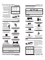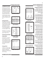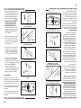
1
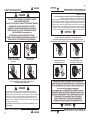
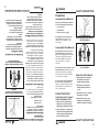
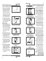
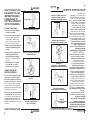
MANUAL PRINTED IN TAIWAN Part #16941 Rev. 02/10 RD v01 Semi-automatic, low velocity, Piston-type fastening tool Operator's Instruction & Training Manual COBRA THIS TOOL IS FOR USE ONLY BY LICENSED OPERATORS. YOU MUST OBTAIN A LICENSE BEFORE USING IT. A TOOL OPERATOR'S CARD WILL BE ISSUED TO YOU AFTER SUCCESSFULLY COMPLETING THE ENCLOSED EXAM AND RETURNING IT TO RECEIVE YOUR CARD AND ACTIVATE YOUR WARRANTY. OPERATOR'S LICENSE CAN ALSO BE OBTAINED AT: www.ramset.com ESTA HERRAMIENTA DEBE SER USADA SÓLO POR OPERADORES AUTORIZADOS. USTED DEBE OBTENER EL PERMISO CORRESPONDIENTE ANTES DE USARLA. SE LE EXPEDIRÁ SU TARJETA DE OPERADOR DE HERRAMIENTA DESPUÉS DE QUE CONTESTE CORRECTAMENTE EL EXAMEN ADJUNTO Y LO ENVÍE, PARA RECIBIR SU TARJETA Y ACTIVAR SU GARANTÍA. EL PERMISO DE OPERADOR TAMBIÉN PUEDE OBTENERSE EN: www.ramset.com COBRA Manual de Instrucciones y Entrenamiento del Operador HERRAMIENTA SEMIAUTOMÁTICA DE FIJACIÓN, DE BAJA VELOCIDAD, TIPO PISTÓN MANUAL IMPRESO EN TAIWAN Part #16941 Rev. 02/10 RD v01 PELIGRO Esta herramienta sólo deben usarla operadores debidamente capacitados y con licencia. Se debe completar satisfactoriamente el programa de capacitación de Ramset para la herramienta y obtener una licencia de operador certificado antes de manejar, cargar u operar esta herramienta. Entrenamiento de seguridad y permiso en www.ramset.com Si se intenta manejar u operar esta herramienta sin la capacitación y la licencia adecuadas se pueden ocasionar lesiones graves al operador o terceras personas. DANGER INTRODUCCIÓN DE SEGURIDAD danger PELIGRO safety inTRODUCtion 2 Responsibility for the safe and proper use of this tool rests with the tool user and the employer. Just as no one can merely read a book about driving an automobile and then hope to drive one safely, no one should attempt to use any Ramset tool without adequate, competent, personal instruction. And just as one must be licensed to drive an automobile, one must also be licensed to use a powder actuated tool. No automobile instruction book or instructor can forewarn a learner against all possibilities and emergencies, nor can Ramset instructors and printed material detail all possible conditions surrounding the use of Ramset tools and products. Never close tool with hand over fastener loading end of the tool. A serious hand injury from penetration by the piston or a discharged fastener could result. S. ATOR OPER IT. A G SED USIN YOU BY LICEN RE ED TO OSED ONLY SE BEFO USE BE ISSU ENCL A LICEN IS FOR CARD THE TOOL OBTA IN CARD WILL ING 'S YOUR T PLET THIS IVE 'S ATOR MUS COM YOU OPER ATOR ULLY IT TO RECETY. OPER et.com rams G TOOL SUCCESSF RNIN WAR RAN www. AT: R AFTE AND RETU YOU R INED BE OBTA EXAM ACTI VATE ALSO AND SE CAN LICEN RA COB ction Instru l tor's Manua Opera ining & Tra TY, OCI L VEL , LOW ING TOO TEN ATIC TOM FAS PE I-AU SEM TON-TY PIS Lea el manual antes de operar esta herramienta. Read manual before operating tool. El operador y terceras personas deben emplear protección para los ojos y oídos. Operators and bystanders must wear eye and hearing protection. ATIC TOM FAS PE I-AU SEM TON-TY PIS TY, OCI L VEL , LOW ING TOO TEN ction Instru l tor's Manua Opera ining & Tra COB RA S. ATOR OPER IT. A G SED USIN YOU BY LICEN RE ED TO OSED ONLY SE BEFO USE BE ISSU ENCL A LICEN IS FOR CARD THE TOOL OBTA IN CARD WILL ING 'S YOUR T PLET THIS IVE 'S ATOR MUS COM YOU OPER ATOR ULLY IT TO RECETY. OPER et.com rams G TOOL SUCCESSF RNIN WAR RAN www. AT: R AFTE AND RETU YOU R INED BE OBTA EXAM ACTI VATE ALSO AND SE CAN LICEN Nunca cierre la herramienta con la mano sobre el extremo de carga de esta herramienta de fijación. Esto puede ocasionar una lesión grave en la mano causada por la penetración del pistón o por el disparo de un elemento de fijación. PELIGRO Del mismo modo que nadie puede sólo leer un libro acerca de cómo conducir un auto- móvil y pretender conducirlo con seguridad, nadie debería intentar hacer uso de una herramienta Ramset sin una instrucción personal adecuada y competente. Y de al misma forma que se debe obtener una licencia para conducir un automóvil, también se debe tener una licencia para hacer uso de una herramienta activada con pólvora. Ningún libro o instructor para aprender a conducir puede prevenir al que está aprendiendo contra todas las posibilidades y emergencias; tampoco pueden los instructores o el material impreso de Ramset detallar todas las posibles condiciones implicadas en la utilización de las herramientas y productos de Ramset La responsabilidad del empleo seguro y apropiado de esta herramienta recae en su usuario y el empleador. INTRODUCCIÓN DE SEGURIDAD PELIGRO danger 2 ATTEMPTING TO HANDLE OR OPERATE THIS TOOL WITHOUT PROPER TRAINING AND LICENSING CAN RESULT IN SERIOUS INJURY TO THE OPERATOR OR BYSTANDERS. YOU MUST SUCCESSFULLY COMPLETE THE RAMSET TRAINING PROGRAM FOR THE TOOL AND OBTAIN A CERTIFIED OPERATOR'S LICENSE BEFORE HANDLING, LOADING, OR OPERATING THIS TOOL. SAFETY TRAINING AND LICENSE CAN BE OBTAINED AT www.ramset.com THIS TOOL IS TO BE USED ONLY BY PROPERLY TRAINED AND LICENSED OPERATORS. DANGER safety introduction DANGER safety instructions 3 2.Using a fastener as a center punch, strike the fastener against the work surface using an average hammer blow and check the results. 1.Always check the material being fastened into for hardness before attempting any fastening operation. Always wear safety goggles when performing this test. Center Punch Test Never fasten into any base material that does not pass the Center Punch test. Failure to assure the suitability of the base material can result in serious injury to the eyes or other body parts. Never fasten into soft base materials, such as drywall or lumber products. These materials may allow the fastener to travel completely through and out the other side, endangering those in the path of the fastener. 4.If the fastener makes a small indention into the material, the material is suitable for fastening. 3.If the material cracks or shatters, the material is too brittle. 2.If the fastener penetrates the material easily, the material is too soft. 1.If the fastener point is flattened, the material is too hard for a powder actuated fastening. Center Punch Test Results never fasten into soft materials such as drywall Never attempt to fasten into very hard or brittle materials such as cast iron, tile, glass, or rock of any type. These materials can shatter, causing the fastener and/or base material fragments to fly free and cause serious injury to tool operator and others. Unacceptable Base Materials Never attempt to fasten into any other type of material. Fastening into other materials can cause blindness or other serious injury. never fasten into very hard or brittle materials • Masonry Joints (see page 8) • Structural Steel • Poured Concrete Powder-actuated fastening is suitable for use in the following base materials only: Acceptable Base Materials Preparation DANGER safety instructions INSTRUCCIONES DE SEGURIDAD Peligro Preparación Materiales base aceptables La fijación por medio de herramientas activadas con pólvora es solamente adecuada para usarse en los siguientes materiales base: • Concreto vertido • Acero estructural • Uniones de mampostería (vea la página 8) Nunca intente realizar las fijaciones en otro tipo de material. La fijación en otros materiales puede ocasionar ceguera u otras lesiones graves. NUNCA INTENTE REALIZAR FIJACIONES SOBRE MATERIALES MUY DUROS O FRÁGILES Materiales base inaceptables Nunca intente realizar las fijaciones en materiales muy duros o frágiles tales como hierro fundido, cerámica, vidrio, o piedra de cualquier tipo. Estos materiales se pueden hacer pedazos, haciendo que los fragmentos del material base o del elemento de fijación salten y ocasionen lesiones graves al operador de la herramienta y a terceros. Nunca fije los elementos sobre materiales base blandos, tales como paredes de yeso o productos de madera. Estos materiales pueden permitir que el elemento de fijación los atraviese completamente y salga por el otro lado, poniendo en peligro a aquellos que se encuentren en el paso del elemento de fijación disparado. Nunca realice las fijaciones en un material base que no pase la prueba de Punzón de Marcar. El no comprobar la idoneidad del material base puede ocasionar lesiones graves a los ojos y a otras partes del cuerpo. Prueba de Punzón de Marcar USE SIEMPRE GAFAS DE SEGURIDAD CUANDO REALICE ESTA PRUEBA. 1.Compruebe siempre la dureza del material que se va a fijar antes de intentar realizar la operación de fijación. 2.Utilizando un elemento de fijación como punzón de marcar, golpee el elemento contra la superficie de trabajo dando un golpe normal de martillo y vea los resultados. Peligro NUNCA INTENTE REALIZAR FIJACIONES SOBRE MATERIALES BLANDOS TALES COMO PAREDES DE YESO Resultados de la prueba de Punzón de Marcar 1.Si la punta del elemento de fijación se aplasta, significa que el material es demasiado duro para fijar por este medio. 2.Si el elemento de fijación penetra muy fácilmente en el material base, significa que éste es demasiado blando. 3.Si el material se quiebra o se fragmenta, significa que es demasiado frágil. 4.Si el elemento de fijación hace una pequeña marca en el material, significa que el material es adecuado para realizar la operación de fijación. INSTRUCCIONES DE SEGURIDAD 3 INSTRUCCIONES DE SEGURIDAD Peligro Seguridad de cargas y selección de cargas 1.Realice siempre una fijación de prueba después de asegurarse que el material base es adecuado para la fijación activada con pólvora. Si no se determina correctamente el nivel de potencia que se debe utilizar puede usarse uno demasiado alto, lo que puede ocasionar que el elemento de fijación atraviese completamente el material de trabajo y ocasione lesiones graves o mortales a terceras personas que se encuentren en la trayectoria del elemento de fijación. 2.Los operadores daltónicos deben siempre seleccionar las cargas por número de carga para evitar el uso de una carga incorrecta por las mismas razones descritas en el párrafo 1 anterior. WITHIN 50 FEET Seguridad en el área de trabajo DANGER Safety is important – Take proper precautions. POWDER ACTUATED TOOL IN USE REALICE SIEMPRE UNA FIJACIÓN DE PRUEBA WARNING never operate the tool around flammable or explosive materials LOS OPERADORES DALTÓNICOS SIEMPRE DEBEN SELECCIONAR LAS CARGAS POR NÚMERO MANTENGA EL ÁREA DESPEJADA DE TERCERAS PERSONAS Y AMONTONAMIENTOS keep work area clear of bystanders & clutter color-blind operators must always select loads by number NUNCA OPERE LA HERRAMIENTA ALREDEDOR DE MATERIALES EXPLOSIVOS O INFLAMABLES ADVERTENCIA always make a test fastening HERRAMIENTA ACCIONADA CON POLVORA EN USO A MENOS DE 15 METROS (50 PIES) La Seguridad Es Importante – Tome Las Precauciones Apropriadas. SIEMPRE COLOQUE LETREROS DE ADVERTENCIA INSTRUCCIONES DE SEGURIDAD 4 Peligro DANGER 1.Los operadores y las terceras personas siempre deben usar gafas de seguridad y accesorios de protección auditiva aprobados. El no cumplir con este requisito puede ocasionar ceguera o lesiones graves a los ojos debido a los fragmentos despedidos y la pérdida del oído debido a la exposición repetida o constante al ruido del disparo del fijador. 2.Mantenga siempre el área de trabajo libre de terceras personas y materiales innecesarios que puedan interferir con la operación segura de la herramienta. La operación de la herramienta en un área congestionada o abarrotada puede afectar su capacidad para operarla de manera segura. 3.Nunca opere la herramienta si hay materiales inflamables o explosivos cerca. Las cargas de pólvora se queman y producen chispas cuando se disparan y pueden inflamar esos materiales o emanaciones. 4.Coloque siempre letreros de advertencia a 50 pies (15 metros) del área donde se efectuará la fijación. Los letreros deben decir: “ADVERTENCIA – Herramienta en uso activada con pólvora”. El no advertir a las personas alrededor puede resultar en lesiones graves para ellas. Comuníquese con ITW Brands al teléphono 1-877-489-2726 (en los EE. UU.) para obtener esta letrero. safety instructions 4 always post warning signs 4.Always post warning signs within 50 ft. of the area where fastening is to be done. Sign must state: “WARNING – Powder Actuated Tool In Use”. Failure to warn others may result in serious injury to them. Contact ITW Brands at 1-877-489-2726 to obtain this sign. 3.Never operate tool if flammable or explosive materials are nearby. Powder loads burn and create sparks when fired and could ignite these materials or fumes. 2.Always keep the work area clear of bystanders and unnecessary materials that could interfere with safe tool operation. Operating the tool in a congested or cluttered area may affect your ability to operate the tool safely. 1.Operators and bystanders must always wear approved eye protection and approved hearing protection. Failure to do so may result in blindness or serious eye injury from flying debris and loss of hearing from constant or repeated unprotected exposure to fastening noise. Workplace Safety 2.Color-blind operators must always select loads by load number to prevent use of an incorrect load for the same reasons as in #1 above. 1.Always make a test fastening after being sure that the base material is suitable for powder actuated fastening. Failure to determine the correct power level to be used may result in the use of excessive power, allowing the fastener to pass completely through the work material, causing serious or fatal injuries to others who may be in the path of the fastener. Loads and Load Selection Safety safety instructions DANGER 11.Using the tool in poorly ventilated areas, cleaning tool or handling loads may result in exposure to lead or other substances known to cause birth defects, and other physical harm. Have adequate ventilation at all times and wash thoroughly after exposure. safety instructions 5 keep tool locked & out of the reach of children 10.Never engage in horseplay with the tool. 9.Never allow anyone not trained to use the tool. 8. N ever carry a loaded tool around the work area. 7.Always keep the tool pointed away from yourself and others. never place hands or body over muzzle opening 6. A lways store tool unloaded and keep the tool and the loads securely locked in a tool box. Keep keys away from children and unlicensed persons. 5.Never place your hand or any other body part over the fastener loading end of tool. Serious hand injury can result from being struck by either a fastener or the tool piston should the tool be accidentally fired. 4.Never load a tool unless you intend to immediately make a fastening. Loading a tool and leaving it unattended in the work area can result in the tool being accidentally discharged by others. 3.Never carry loose strip loads in pockets with pins or other hard objects. never load tool unless it is to be used immediately always do a daily function Check before loading the tool 2.Always load tool using a strip load selected directly from a box indicating the power load type and number. Never attempt to use loose strip loads that could be misidentified. 1.Always be sure tool is operating properly before attempting to use it. Follow the “Daily Function Check” shown to the right and described on page 9. Tool Handling Safety safety instructions DANGER INSTRUCCIONES DE SEGURIDAD Peligro Seguridad en el manejo de la herramienta 1.Compruebe siempre que la herramienta esté funcionando correctamente antes de intentar usarla. Siga las instrucciones de “Verificación diaria de funcionamiento” que se muestran a la derecha y se describen en la página 9. 2.Cargue la herramienta siempre usando una tira de cargas seleccionada directamente de una caja que indique el tipo y el número de la potencia de carga. Nunca trate de usar tiras de cargas sueltas que pueden estar mal identificadas. 3.Nunca lleve tiras de cargas en los bolsillos junto con pernos u otros objetos duros. 4.Nunca cargue una herramienta a menos que la vaya a utilizar inmediatamente para efectuar una fijación. Si se carga una herramienta y se le deja desatendida en el área de trabajo puede ocasionar que alguna otra persona la descargue accidentalmente. 5.Nunca coloque la mano ni ninguna otra parte de su cuerpo sobre el extremo donde se cargan los elementos de fijación en la herramienta. Se pueden recibir lesiones serias en la mano si un elemento de fijación o el pistón de la herramienta se disparan accidentalmente. 6.Guarde siempre la herramienta descargada y manténgala junto a las cargas, bajo llave, en una caja de herramientas. Conserve las llaves fuera del alcance de niños o personas sin licencia. 7.Mantenga siempre la herramienta apuntando hacia un lugar alejado de usted y de terceras personas. 8. Nunca transporte una herramienta cargada alrededor del área de trabajo. 9.Nunca permita que personas sin capacitación usen la herramienta. 10.Nunca retoce o juegue con la herramienta. 11.La utilización de la herramienta, limpiarla o manejar sus cargas en áreas mal ventiladas puede resultar en una exposición a plomo u otras substancias conocidas como causantes de defectos de nacimiento y otros daños físicos. Mantenga en todo momento una ventilación adecuada y lávese a conciencia después de cada exposición. Peligro SIEMPRE EFECTUÉ UNA COMPROBACIÓN DIARIA DE FUNCIONAMIENTO ANTES DE CARGAR LA HERRAMIENTA NUNCA CARGUE LA HERRAMIENTA A MENOS QUE LA VAYA A UTILIZAR INMEDIATAMENTE NUNCA COLOQUE LAS MANOS O EL CUERPO DELANTE DE LA BOCA DE LA HERRAMIENTA MANTENGA LA HERRAMIENTA BAJO LLAVE Y LEJOS DEL ALCANCE DE LOS NIÑOS INSTRUCCIONES DE SEGURIDAD 5 Peligro INSTRUCCIONES DE SEGURIDAD EL NO SEGUIR LAS INSTRUCCIONES PUEDE OCASIONAR LESIONES AL OPERADOR DE LA HERRAMIENTA O A TERCERAS PERSONAS Guarda de ProtecciÓn contra astillas SIEMPRE QUE SEA POSIBLE USE UNA GUARDA DE PROTECCIÓN 90 o SOSTENGA SIEMPRE LA HERRAMIENTA PERPENDICULAR A LA SUPERFICIE DE TRABAJO NUNCA INTRODUZCA UN ELEMENTO DE FIJACIÓN CERCA DE UN BORDE o Seguridad en la aplicación de elementos de fijación DANGER HOLD TOOL FIRMLY AGAINST the WORK SURFACE FOR AT LEAST 30 SECONDS. NEVER DRIVE A FASTENER CLOSE TO AN EDGE ALWAYS HOLD the TOOL PERPENDICULAR TO the WORK SURFACE 90 USE SPALL GUARD WHENEVER POSSIBLE spall guard SOSTENGA FIRMEMENTE LA HERRAMIENTA CONTRA LA SUPERFICIE DE TRABAJO DURANTE POR LO MENOS 30 SEGUNDOS INSTRUCCIONES DE SEGURIDAD 6 Peligro DANGER 1.Utilice únicamente la herramienta para fijar sobre un material base adecuado. 2.Nunca dispare la herramienta sin un elemento de fijación. El disparo de la herramienta sin un elemento de fijación hará que el pistón golpee la superficie de trabajo, y puede ocasionarle lesiones graves a usted y a otros que se encuentren en el área de trabajo. 3.Use siempre que sea posible la guarda de protección contra astillas para reducir partículas sueltas o fragmentos volando por los aires. 4.Sostenga siempre la herramienta de forma perpendicular y firmemente contra la superficie de trabajo cuando efectúe la fijación. El no hacerlo así puede hacer que el elemento de fijación rebote. 5.Nunca intente hacer penetrar un elemento de fijación cerca de un borde o de otro elemento de fijación. Vea las pautas en la página 8. SIGA SIEMPRE EL PROCEDIMIENTO DE FALLA DE DISPARO Si la herramienta no dispara después de activar el gatillo, continúe presionando la herramienta contra la superficie de trabajo durante por lo menos otros 30 segundos. Abra entonces cuidadosamente la herramienta y saque la tira de carga y colóquela en un recipiente con agua o algún otro líquido no inflamable. Nunca deseche a la basura una tira de cargas con cargas activas. Si la herramienta se traba o se atasca con una carga activa de pólvora, mantenga la herramienta apuntando en una dirección segura, y colóquele inmediatamente una etiqueta que diga: “Peligro. Defectuosa. ¡No usar!”. Coloque la herramienta bajo llave en una caja de herramientas y para recibir asistencia técnica, llame al 1-877-ITW-BRANDS (1-877-489-2726). safety instructions 6 If the tool becomes stuck or jammed with a live powder load, keep the tool pointed in a safe direction, and immediately tag it, “Danger–defective–do not use”. Lock the tool in a tool box and call 1-877-ITWBRANDS (1-877-489-2726) for technical assistance. If the tool does not fire after the normal firing sequence, continue to hold the depressed tool against the work surface for at least 30 seconds. Then carefully lower the tool, remove the strip load and put it in a can of water or other non-flammable liquid. Never carelessly discard a strip with live loads into a trash container. Always follow the misfire procedure. 5.Never attempt to drive a fastener close to an edge or to another fastener. See page 8 for guidelines. 4.Always hold the tool perpendicular to and firmly against the work surface when making a fastening. Failure to do so could allow a fastener to ricochet. 3.Always use the spall guard whenever possible to minimize flying particles or debris. 2.Never fire the tool without a fastener. Firing a tool without a fastener will cause the piston to strike the work surface, and may cause serious injury to you and others in the work area. 1.Only use the tool for fastening into a suitable base material. Fastener Driving Safety Failure to follow instructions can cause injury to the tool operator or to bystanders. safety instructions Fasteners / Loads 7 Power Catalog Load Case Level Number Color Color Always perform the center punch test described on page 3 to test the base material. Always make a test fastening using the lowest power level first. If more power is required to set the fastener, use the next higher power level until the powder level necessary to drive the fastener is reached. 2 3 4 5 2RS27 3RS27 4RS27 5RS27 Brown Green Yellow Red Brass Brass Brass Brass Ramset RS 27 strip loads are specially made for use in the Ramset Cobra+ Tool. The power level of the load is indicated by the number marked on each box, the color of the box, and the color on the tip of each load. As the number increases, the power rs 27 10 shot strip load level also increases. Loads For 1/2" and 3/4" Diameter Conduit with 1" Pre-mounted Fastener Ceiling Clip with 1" or 1-1/4" pre-mounted .145 Shank Pin and Ceiling Clip with 1" or 1-1/4" pre-mounted .150/.180 shank pin. ELEMENTOS DE FIJACIÓN / CARGAS Su herramienta Ramset Cobra+ sólo usa elementos de fijación y cargas Ramset como las mostraciones más abajo o en el catálogo de productos. Peligro Nunca use ningún otro tipo de elementos de fijación o tirillas de cargas en la herramienta Cobra+. El uso de otros tipos de elementos de fijación puede ocasionar una descarga accidental de la carga, daños a la herramienta, rendimiento deficiente de la operación de fijación, o crear riesgos de lesiones graves al operador y a terceras personas. ELEMENTOS DE FIJACIÓN ESPIGAS GUÍA ESTRIADAS CON CABEZA DE PLÁSTICO DE 0.300 PULGADAS ESPIGAS GUÍA ESTRIADAS CON CABEZA DE PLÁSTICO DE 0.300 PULG. CON ARANDELA DE 7/8 PULG. Diámetro del vástago 0.145 pulg. y largos de 1/2 a 3 pulg. Pernos roscados de 1/4 pulg.-20 Diámetro del vástago 0.145 pulg. y largos de 1/2 pulg. y 1 pulg., y roscas de 1/2, 3/4 y 1 pulg. de largo. conduit clip assemblies ESPIGAS GUÍA CON CABEZA PLANA DE 8 mm PULG. .145 Shank Diameter in Shank Lengths from 1/2" to 1" Diámetro del vástago 0.145 pulg. y largos de 1/2 pulg. a 1 pulg. 8 mm head top-hat drive pins ceiling clip assemblies .150 Straight Shank in Shank Lengths from 1/2" to 7/8" .150/.180 Step Shank in Lengths from 1" to 1-7/8" CONJUNTOS SUJETADORES PARA CONDUCTOS .145 Shank Diameter in Shank Lengths of 1/2" and 1" and thread lengths of 1/2", 3/4" and 1" .300 head power point plastic fluted drive pins Para conductos de 1/2 y 3/4 pulg. con elemento de fijación de 1 pulg. premontado. 1/4" - 20 Threaded studs Diámetro del vástago de 0.145 pulg. y largos de 1 pulg. a 3 pulg. ESPIGAS GUÍA ESTRIADAS CON CABEZA DE PUNTA DE PODER DE PLÁSTICO DE 0.300 PULG. Diámetro del vástago recto de 0.150 pulg. y largos de 1/2 pulg. a 7/8 pulg. Diámetro del vástago escalonado de 0.150 /0.180 pulg. y largos de 1 a 1-7/8 pulg. CONJUNTOS SUJETADORES PARA TECHOS Sujetadores para techos con elementos de fijación de 1 ó 1-1/4 pulg. con vástago de 0.145 pulg. de diámetro premontados y sujetadores para techos con elementos de fijación de 1 ó 1-1/4 pulg. con cuerpo de 0.150/0.180 de diámetro premontados. CARGAS .145 Shank Diameter in Shank lengths from 1/2" to 3" Las tiras de cargas Ramset RS 27 están especialmente fabricadas para usarse con la herramienta Cobra+. .300 head plastic fluted drive pins .145 Shank Diameter in Shank Lengths from 1" to 3" .300 head plastic fluted drive pins with 7/8" washer Fasteners Never use any other types of fasteners or strip loads in the Ramset Cobra+ tool. Use of other types of fasteners or loads may cause unintentional load discharge, damage the tool, cause poor fastening performance, or create a risk of serious injury to the operator or bystanders. rs 27 10 shot strip load NIVEL DE NÚMERO DE COLOR COLOR PODER CATÁLOGO DE CARGA DE CAJA Danger Your Ramset Cobra+ tool uses only the Ramset fasteners and loads shown below or listed for the tool in the Product Catalog. 2 3 4 5 2RS27 3RS27 4RS27 5RS27 Fasteners / Loads Café Verde Amarillo Rojo Bronce Bronce Bronce Bronce El nivel de poder de las cargas viene indicado por un número marcado en cada caja, el color de la caja y el color de la punta de cada carga. A medida que aumenta el número, también aumenta el nivel de poder de la carga. Realice siempre la prueba de Punzón de centro descrito en la página 3 para probar el material base. Realice siempre una fijación de prueba usando primero una carga de nivel de potencia más bajo. Si se necesita más poder para fijar el elemento de fijación, use el siguiente nivel de poder hasta obtener el necesario para lograr la penetracíon del elemento. ELEMENTOS DE FIJACIÓN / CARGAS 7 APLICACIONES DE FIJACIÓN Fastening Applications 8 APLICACIONES DE FIJACIÓN MÍn 3 pulg. MÍn 3 pulg. ESPACIO EN MADERA A CONCRETO MÍn 3 pulg. 1-1/2" Min. Su herramienta Ramset se puede usar para satisfacer una amplia gama de necesidades de fijación en una variedad de materiales base. Se deben leer y seguir estas importantes pautas de fijación para ayudar a obtener mejores resultados en la utilización de su herramienta, elementos de fijación y cargas de pólvora, así como también para realizar estas operaciones de sujeción de manera segura y efectiva. Los elementos de fijación activados por pólvora son permanentes por lo que intentar quitar uno de ellos de concreto o acero puede ocasionar lesiones graves. Spacing — steel to steel 1/2" Min. Fijación en concreto Siempre mantenga un espacio de 3 pulgadas como mínimo entre los elementos de fijación y otras 3 pulgadas alejado de los bordes o extremos cuando se efectúen fijaciones sobre en concreto. El espesor del concreto debe ser por lo menos 3 veces más grueso que la profundidad de penetración deseada. La excepción más importante a las 3 pulgadas de distancia de un borde puede presentarse en las aplicaciones con largueros donde, por necesidad, la distancia al borde es más reducida. Al penetrar los elementos de fijación muy cerca de los bordes o entre sí, puede hacer que se fracture el borde del concreto o que el elemento de fijación se dispare al aire. Fijación en bloques de concreto o en paredes de mampostería PENETRACIÓN – METAL DE BAJO CALIBRE SOBRE CONCRETO MÍn 3 pulg. ESPACIO – FRANJA DE ENRASADO SOBRE CONCRETO MÍn 1/2 pulg. MÍn 1-1/2 pulg. Min. A pesar de que esta aplicación no se recomendada, cuando se usa, es necesario tener cuidado de observar la distancia de 3 pulgadas al borde para evitar agrietamientos del bloque y penetración excesiva del elemento y así evitar la degradación del valor de sujeción. Las fijaciones se pueden efectuar en las uniones horizontales pero no en las verticales. spacing – furring strip to concrete 3" Min. penetration – thin gauge metal to concrete 3" spacing wood to concrete Fijación sobre acero 3" Min. ESPACIO – EN ACERO SOBRE ACERO 3" Min. Fastening Applications Su herramienta Ramset se puede usar para fijar en superficies planas de acero estructural. Cuando se efectúen fijaciones sobre acero, siempre mantenga un espacio mínimo de 1-1/2 pulgada entre los elementos de fijación y 1/2 pulgada de distancia de cualquier borde. Your Ramset tool can be used for fastening on the flat surfaces of structural steel. When fastening into steel, always maintain a minimum spacing of 1-1/2" between fastenings and 1/2" from any edge. Fastening to Steel While this application is not recommended, when used, it is necessary to take care to observe a 3" edge distance to avoid cracking the block and over penetration of the fastener to avoid loss of holding value. Fastenings may be made into the horizontal joint but not into the vertical joint. Fastening to Concrete Block or to Masonry Walls Driving fasteners too close to an edge or too close to each other can cause the concrete edge to fail or fasteners to fly free. When fastening into concrete, always maintain a minimum spacing of 3" between fastenings and 3" from any free edge. Concrete thickness should be at least three times the intended penetration depth into the concrete. The primary exception to the 3" edge distance can occur in a sill plate application where, by necessity, the edge distance is reduced. Fastening to Concrete Powder actuated fastenings are permanent fastenings so attempting to remove a fastener from concrete or steel may result in serious injury. Your Ramset tool can be used for a wide range of fastening needs in a variety of base materials. Reading and following these important fastening guidelines will help you get the best results from your tool, fasteners, and powder loads, as well as help you perform these fastening operations safely and effectively. Fastening Applications APLICACIONES DE FIJACIÓN 8 tool operating instructions 9 insert load strip into the Opening in the bottom of the handle 3.With the tool pointed in a safe direction and finger away from the trigger, insert a strip load into the bottom of the handle and push it in until your finger is in firm contact with the handle recess. 2.With finger off the trigger, place the fastener, point out, into the muzzle end of the tool until the point end is inside the muzzle. never load a fastener with your finger on the trigger. Do not use excessive force when inserting a fastener. Stop immediately if excessive force is required, inspect the barrel to find out why the fastener is not entering the muzzle freely. Do not continue loading unless the problem is corrected. 1.After checking to be sure that the tool is not loaded, point it in a safe direction and be sure that the barrel is fully extended and then close the tool to the semi-closed position. This assures that the piston is in position for the next fastening. Use the spall guard every time possible to minimize the risk of being struck by flying debris. insert fastener into the muzzle end of the tool with the point out fully open and close tool to the semi-closed position Keep hands away from muzzle Operating the RAMSET Cobra Tool Daily Function Test Always check the tool first to make sure it does not contain a strip load or fastener. Test the tool several times by depressing the muzzle bushing fully on a hard surface and pulling the trigger. You should hear an audible click as the firing pin releases. Let up on the tool, and check to be sure the barrel has opened to the semiopen position. Perform the function test with empty, unloaded tool INSTRUCCIONES DE FUNCIONAMIENTO DE LA HERRAMIENTA FUNCIONAMIENTO DE LA HERRAMIENTA Prueba diaria de funcionamiento. Siempre compruebe primero la herramienta para cerciorarse de que no contenga una tira de cargas o elementos de fijación. Pruebe la herramienta varias veces presionando completamente el buje de la boca sobre una superficie dura y activando el gatillo. Debe oírse un clic en el momento en que se desengancha de percutor. Levante la herramienta y compruebe que el cañón se ha abierto a la posición semiabierta. REALICE LA PRUEBA DE FUNCIONAMIENTO CON LA HERRAMIENTA VACÍA Y DESCARGADA OPERACIÓN DE LA HERRAMIENTA COBRA 1.Después de comprobar que la herramienta no esté cargada, apúntela en una dirección segura y compruebe que el cañón esté totalmente extendido y cierre entonces la herramienta hasta la posición semiabierta. Esto asegura que el pistón se encuentra en posición correcta para la próxima operación de fijación. Use la guarda de protección contra astillas siempre que sea posible para reducir el riesgo de que lo golpee alguno de los fragmentos despedidos. 2.Con el dedo alejado del gatillo, coloque el elemento de fijación con su punta hacia afuera dentro del extremo de la boca de la herramienta hasta que la punta entre totalmente. NUNCA cargue un elemento de fijación cuando su dedo esté sobre el gatillo. NO use fuerza excesiva para insertar un elemento de fijación. DETÉNGASE inmediatamente si necesita usar fuerza excesiva, e revise el cañón para averiguar por qué el elemento de fijación no entra libremente dentro de la boca. NO continúe cargando hasta que se solucione el problema. 3.Apunte la herramienta en una dirección segura y con el dedo alejado del gatillo, inserte una tira de cargas en la parte inferior de la empuñadura y presiónela hasta que su dedo haga contacto con el hueco en la empuñadura. Mantenga Las manos alejadas de la boca ABRA COMPLETAMENTE Y CIERRE LA HERRAMIENTA A LA POSICIÓN SEMIABIERTA INSERTE EL ELEMENTO DE FIJACIÓN EN EL EXTREMO DE LA BOCA DE LA HERRAMIENTA CON LA PUNTA HACIA FUERA INSERTE LA TIRA DE CARGA EN LA ABERTURA EN EL FONDO DE LA EMPUÑADURA TOOL OPERATION tool operating instructions INSTRUCCIONES DE FUNCIONAMIENTO DE LA HERRAMIENTA 9 INSTRUCCIONES DE FUNCIONAMIENTO DE LA HERRAMIENTA 4.Sostenga la herramienta con ambas manos en forma perpendicular (90°) a la superficie de trabajo y presione firmemente para contraerla totalmente. Mantenga una presión firme hacia abajo sobre la herramienta con ambas manos y jale del gatillo para clavar el elemento de fijación. NO PRESIONE LA HERRAMIENTA CONTRA NADA MÁS QUE SOBRE LA SUPERFICIE DE TRABAJO DESEADA. Al sostener la herramienta firmemente en su lugar se producirá una fijación de calidad más uniforme y se reducirá al mínimo el desgaste o los daños a la herramienta. 5.Después de hacer la fijación, abra completamente y luego cierre la herramienta a la posición semiabierta. Esto restablece el pistón y coloca una nueva carga en su lugar para la siguiente operación de fijación. 90 o SOSTENGA LA HERRAMIENTA FIRMEMENTE Y DE FORMA PERPENDICULAR A LA SUPERFICIE DE TRABAJO Mantenga Las manos alejadas de la boca ABRA COMPLETAMENTE LA HERRAMIENTA Y LUEGO CIÉRRELA A LA POSICIÓN SEMIABIERTA 6.Inserte otro elemento de fijación en el extremo de la boca de la herramienta como lo hiciera anteriormente y la herramienta quedará lista para la siguiente operación de fijación. Mantenga su dedo retirado del gatillo hasta que la herramienta esté en posición para clavar el elemento de fijación. 7.Para sacar una tira de cargas usada o parcialmente usada de la herramienta, saque la tira de la parte superior de la herramienta. No intente sacar la tira tirando hacia fuera de la parte inferior de la empuñadura. NUNCA trate de sacar una tira de cargas atascada o trabada que contenga cargas sin disparar. En caso de que se “atasque” una tira de cargas, para recibir asistencia técnica, llame al 1-877ITW-BRANDS (1-877-489-2726). Ajuste de potencia El nivel de potencia de la Cobra+ puede ajustarse para lograr una penetración óptima en el material base. Gire la rueda de ajuste de potencia, la cual está situada en el costado de la herramienta. POWER LEVEL ADJUSTMENT remove the load strip only from the top of the tool Insert the next fastener INSERTE EL SIGUIENTE ELEMENTO DE FIJACIÓN Fully open the tool and then close it to the semi-closed Position Keep hands away from muzzle RETIRE LA TIRA DE CARGAS SÓLO DESDE LA PARTE SUPERIOR DE LA HERRAMIENTA Hold the tool firmly and perpendicular to the work surface Si las puntillas no se introducen lo suficiente con el nivel de potencia puesto al máximo (3), utilice la siguiente carga más potente. 90 o Si las puntillas se introducen demasiado con el nivel de potencia puesto al mínimo (1), utilice la siguiente carga menos potente. tool operating instructions 10 If pins are still overdriven when power level is set at minimum (1), switch to the next lower load. If pins are still underdriven when power level is set at maximum (3), switch to the next higher load. The power level of the Cobra+ can be adjusted up or down for optimum penetration of the base material. Turn the power adjust wheel located on the side of the tool. Power Adjust 7.To remove a used or partially used load strip from the tool, pull the strip out from the top of the tool. Do not try to remove the strip by pulling it out from the bottom of the handle. NEVER try to remove a jammed or stuck load strip. Should a “jammed” load strip occur, call 1-877-ITW-BRANDS (1-877489-2726) for technical assistance. 6.Insert another fastener in the muzzle end of the tool as before and the tool is ready for the next fastening. Keep your finger off of the trigger until the tool is in position to drive the fastener. NIVEL DE POTENCIA AJUSTABLE 5. After making the fastening, fully open and then close the tool to the semiclosed position. This resets the piston and indexes a new load into place for the next fastening. 4.Hold the tool perpendicular (90˚) to the work surface with both hands, and press down firmly to fully depress the tool. Maintain firm downward pressure on the tool with both hands and pull the trigger to drive the fastener. DO NOT DEPRESS THE TOOL AGAINST ANYTHING OTHER THAN THE INTENDED WORK SURFACE. Holding the tool firmly in place while fastening will produce more consistent fastening quality, and minimize tool wear or damage. Tool Operating Instructions INSTRUCCIONES DE FUNCIONAMIENTO DE LA HERRAMIENTA 10 – Failure of tool to stay closed when held in the downward position – Failure to index strip troubleshooting 11 – Strip not inserted in tool correctly or is damaged – Check load strip. Properly dispose of damaged strip. (see page 6) – Damaged indexing mechanism – Call 1-877-ITW-BRANDS (1-877-489-2726) – Retaining ball missing – Call 1-877-ITW-BRANDS (1-877-489-2726) RESOLUCIÓN DE PROBLEMAS CONSULTE EL DIAGRAMA DE PIEZAS PARA ARMAR CORRECTAMENTE LAS MISMAS – Penetración excesiva de elementos de fijación – La herramienta no dispara – Broken or damaged parts – Tag tool with warning “Defective–Do Not Use”. Place in a locked container and contact your local Ramset representative for service – Excessive power – Turn power adjust wheel down –C hange to next lower power level load strip – Soft base material – Check base material (see page 3) – Failure to depress completely – See “Tool does not completely depress” – Excessive dirt buildup on breech face not allowing proper penetration of firing pin – After following misfire procedure, check firing pin indentation on load. Clean breech face – Firing pin and/or breech damaged – Replace damaged parts – Tool does not completely depress – Misassembled or damaged parts – Check all parts in the receiver for damage or improper assembly – Reduction or loss of power – Power adjust dial turned down – Piston not being returned to the full rear position – Adjust power dial to increase power level – Barrel must be pulled completely open to properly position the piston – Worn or damaged piston or piston ring – Replace worn or damaged parts Worn or broken pawl – – Replace pawl – Excessive dirt buildup – Clean tool thoroughly – Damaged or bent piston – Replace piston – Tool cannot be cocked or opened – La herramienta no se contrae completamente – Reducción o pérdida de potencia – Falla en la colocación de la tira de cargas – La herramienta no se queda cerrada cuando se apunta en una posición hacia abajo – Potencia excesiva – Gire al nivel más bajo la rueda de ajuste de potencia – Use una tira de cargas del siguiente nivel de potencia más alto –R eemplace las piezas dañadas – El percutor o la camara están dañados – Después de haber completado el procedimiento de falla de disparo, compruebe la marca del percutor sobre la carga. Revise la cara de la camara – La acumulación excesiva de suciedad en la cara de la camara no permite la penetración correcta del percutor. – Vea el párrafo “ La herramienta no se contrae completamente”. – No se contrae completamente – Verifique el material base (vea la página 3). – Material base blando – Piezas mal armadas o dañadas – Pueda de ajuste de potencia girada hasta abajo – Revise todas las piezas del receptor para buscar daños o armado incorrecto – Gire la rueda de ajuste para aumentar el nivel de potencia –R eemplace las piezas desgastadas o dañadas – Pistón o anillo del pistón desgastados o dañados – Se debe tirar completamente del cañón para colocar correctamente el pistón – El pistón no se retrae hasta su posición trasera total – Retén desgastado o dañado –L a herramienta no se puede amartillar o abrir – Acumulación excesiva de suciedad – Reemplace el retén – Limpie completamente la herramienta – Coloque una etiqueta de advertencia en la herramienta que diga: “Defectuosa, ¡No usar!”. Encierre la herramienta bajo llave en una caja y llame a su representante de Ramset para obtener servicio. – Piezas dañadas o rotas – Reemplace el pistón – Pistón dañado o doblado – Tool fails to fire – Overdriving of fasteners REFER TO PARTS SCHEMATIC FOR PROPER ASSEMBLY OF PARTS troubleshooting – llame al 1-877-ITW-BRANDS (1-877-489-2726) – Falta la esfera de retención – llame al 1-877-ITW-BRANDS (1-877-489-2726) – El mecanismo de avance está dañado – Revise la tira de cargas. Deseche correctamente la tira dañada (vea la página 6). – La tira no se insertó correctamente en la herramienta o está dañada RESOLUCIÓN DE PROBLEMAS 11 diagrama de piezas diagrama de piezas 12 parts schematic 12 parts schematic Parts list / maintenance 13 Always function test the tool after performing any service. See Page 9 for details on the function test. Heavy or constant exposure to dirt and debris may require that the tool be cleaned more extensively. Complete disassembly and cleaning of all parts may be necessary to restore the tool to normal operation. General maintenance should be performed every six months or more often if the tool is subjected to heavy use. Call 1-877-ITW-BRANDS (1-877-4892726) for technical assistance. complete cleaning / general maintenance All front end parts shown in the disassembly section are to be cleaned daily with a good detergent oil and wire brush. Remove all dirt and carbon buildup and wipe parts dry with a clean rag. Check all parts for wear or damage before reassembly and replace or repair any worn or damaged parts. Normal cleaning Always make sure tool is not loaded before performing any service or repair and always wear safety goggles when cleaning or servicing the tool. improperly maintained tools can cause serious injuries to tool operators and bystanders, clean tool daily maintenance Key Part No. 1 2 3 4 5 6 7 8 9 10 11 12 13 14 15 16 17 18 19 20 21 22 23 24 25 26 SC301500 SPALL GUARD SC385009 FRONT BARREL (BASEPLATE) SC301011A SHEAR CLIP (PKG. OF 3) SC305010 FASTENER GUIDE SC385903 PISTON ASSEMBLY SC301208 PISTON RING SC302012 PAWL (STOP) SC385006 REAR BARREL (PISTON SLEEVE) SC301014A BARREL RETENTION ASSEMBLY SC301016 PUSH PIN SC301046A DETENT BALL ASSEMBLY SC301034A TRIGGER ASSEMBLY AND PIN SC385001 TOOL BODY SC301113 BOLT (2) SC301300A SEAR HOLDER ASSEMBLY SC301531 SPRING, ADVANCE BAR SC301400 FIRING PIN ASSEMBLY SC301026A FIRING PIN SPRING ASSEMBLY SC301600HANDLE ASSEMBLY SC355600 POWER ADJUST ASSEMBLY SC355610 ADJUST PIN and WHEEL ASSEMBLY SC355601 PANEL SC355602 PIN, PANEL SC355603 SPRING, PANEL SC355604 SCREW, LONG SC355605 SCREW, SHORT Description LISTA DE PIEZAS / MANTENIMIENTO LISTA DE PIEZAS DE LA HERRAMIENTA COBRA+ CLAVE No. DE PIEZA DESCRIPCIÓN 1 SC301500 GUARDA DE PROTECCIÓN CONTRA ASTILLAS 2 SC385009 CAÑÓN FRONTAL (PLACA BASE) 3 SC301011A CLIP DESLIZANTE (PAq. DE 3) 4sc305010 GUÍA PARA LOS ELEMENTOS DE FIJACIÓN 5sc385903 CONJUNTO DEL PISTÓN 6sc301208 ANILLO DEL PISTÓN 7 SC302012 RETÉN (LIMITADOR) 8sc385006 CAÑÓN POSTERIOR (MANGUITO DEL PISTÓN) 9sc301014a CONJUNTO DE RETENCIÓN DEL CAÑÓN 10sc301016 PERNO DE EMPUJE 11sc301046a CONJUNTO DE LA ESFERA DE RETENCIÓN 12sc301034A CONJUNTO DEL GATILLO Y PERCUTOR 13sc385001 CUERPO DE LA HERRAMIENTA 14sc301113 PERNO (2) 15sc301300a CONJUNTO DEL SUJETADOR DEL FIADOR 16sc301531 RESORTE, BARRA DE AVANCE 17sc301400 CONJUNTO DEL PERCUTOR 18sc301026a CONJUNTO DEL RESORTE DEL PERCUTOR 19sc301600 CONJUNTO DE LA EMPUÑADURA 20 SC355600ensamble de ajuste de potencia 21 SC355610ensamble de pasador y rueda de ajuste 22sc355601panel 23sc355602pasador, panel 24sc355603resorte, panel 25 SC355604tornillo, largo 26 SC355605tornillo, corto MANTENIMIENTO LAS HERRAMIENTAS MANTENIDAS INCORRECTAMENTE PUEDEN OCASIONAR LESIONES GRAVES A SUS OPERADORES Y A TERCERAS PERSONAS. LIMPIE LA HERRAMIENTA DIARIAMENTE Verifique siempre que la herramienta no esté cargada antes de realizar cualquier operación de servicio o reparación y utilice siempre gafas de seguridad cuando esté limpiándola o dándole servicio. LIMPIEZA NORMAL Todas las piezas del extremo anterior mostradas en la sección de desarmado se deben limpiar diariamente con un buen aceite detergente y un cepillo de alambre. Elimine la acumulación de suciedad y carbón y seque las piezas con un paño limpio. Revise el desgaste o el daño de todas las piezas antes de volver a armar la herramienta y reemplace o repare cualquiera que se encuentre desgastada o dañada. LIMPIEZA COMPLETA / MANTENIMIENTO GENERAL El uso continuo o la exposición constante a suciedad o los desechos puede requerir que la herramienta se limpie más exhaustivamente. Puede ser necesario desarmarla completamente y limpiar todas las piezas para restaurar la herramienta a su condición normal. El mantenimiento general se debe realizar cada seis meses o más frecuentemente si la herramienta se usa intensamente. Para recibir asistencia técnica, llame al 1-877-ITW-BRANDS (1-877-489-2726). SIEMPRE COMPRUEBE LA HERRAMIENTA HACIÉNDOLA FUNCIONAR DESPUÉS DE DARLE CUALQUIER TIPO DE SERVICIO. CONSULTE LA PÁGINA 9 PARA OBTENER DETALLES SOBRE LA PRUEBA DE FUNCIONAMIENTO. cobra+ tool parts list Parts list / maintenance LISTA DE PIEZAS / MANTENIMIENTO 13 DESARMADO DESARMADO DE LA HERRAMIENTA disassembly 14 separate the front barrel from the rear barrel 1.Usando un destornillador plano o la punta de un elemento largo de fijación desprenda el clip de retención de el retén haciéndolo girar. HACIENDO GIRAR EL CLIP SUJETADOR DEL CAÑÓN DESPRÉNDALO DEL RETÉN 5.Separate the front barrel and guide from the rear barrel assembly. remove the shear clip 2.Quite el retén levantándolo y retirándolo del cuerpo de la herramienta. 4.Unseat and remove the shear clip by prying it up with a flat blade screwdriver or fastener point. Remove the clip from the barrel by prying it up and away from the groove in the barrel. Use care to keep the clip from flying free when it is removed. Saque el RETÉN remove the barrel assembly 3.Deslice el conjunto del cañón hacia afuera del cuerpo de la herramienta. 3.Slide the front barrel assembly out of the tool body. SAQUE EL CONJUNTO DEL CAñÓN remove the pawl 4.Desmonte y quite el clip deslizante levantándolo con un destornillador plano o la punta de un elemento de fijación. Quite el clip del cañón levantándolo y sacándolo de la muesca en el cañón. Tenga cuidado para evitar que el clip salga despedido. 2.Remove the pawl by lifting it up and away from the tool body. QUITE EL CLIP DESLIZANTE 5.Separe el cañón frontal y la guía del conjunto del cañón posterior. Rotate the barrel retention clip away from pawl 1.Rotate the barrel retention clip off of the pawl using a flat blade screwdriver or the point of a long fastener. SEPARE EL CAÑÓN FRONTAL DEL POSTERIOR Tool disassembly disassembly DESARMADO 14 Always perform the daily function test before using the tool after cleaning or servicing. 9.Align the groove in the rear barrel with the pawl opening in the tool body when placing the barrel assembly into the tool body. Replace the pawl and install the barrel retention clip. disassembly 15 align the barrel assembly groove with the pawl opening Align Align the front and rear barrel grooves 8.Reassemble the tool in the reverse order of disassembly. When sliding the front barrel onto the rear barrel, align the groove in the rear barrel with the groove in the front barrel. Align Grind the piston tip flat and bevel the edge 7.Check the piston tip for damage and grind flat. The tip of the piston must be 90˚ to the shank. Grinding should only be done by qualified personnel. The minimum overall length of the piston must not be less than 5-5/8" long. When less than 5-5/8" long, the piston must be replaced to avoid tool damage. The tool is now disassembled for normal cleaning. Inspect all parts for wear or damage and clean or replace as required. Use detergent oil and cleaning brushes to remove dirt and powder residues. Wipe all parts dry before reassembly. Wear safety goggles when cleaning tool parts. remove the piston and fastener guide 6.Slide the piston out of the rear barrel assembly and slide the guide out of the front barrel. 6.Deslice el pistón fuera del conjunto del cañón y deslice la guía fuera del barril frontal. La herramienta está ahora desarmada para su limpieza normal. Revise todas las piezas para ver si están desgastadas o dañadas y limpie y reemplace según sea necesario. Use un aceite detergente y cepillos limpiadores para quitar toda la suciedad y residuos de polvo. Seque con un trapo todas las piezas antes de volver a armar. Use gafas de seguridad cuando esté limpiando las piezas de la herramienta. 7.Revise la punta del pistón para ver si está dañada y rectifíquela plana. La punta del pistón debe quedar en ángulo de 90° con respecto al vástago. Sólo personal competente debe realizar la rectificación. El largo total del pistón debe ser de por lo menos de 5-5/8 pulgadas; si mide menos se debe reemplazar este pistón para evitar daños a la herramienta. DESARMADO QUITE EL PISTÓN Y LA GUÍA DE LOS ELEMENTOS DE FIJACIÓN 5/16 pulg. RECTIFIQUE PLANA LA PUNTA DEL PISTÓN Y BISELE LOS BORDES 8.Vuelva a armar la herramienta en orden inverso del desarmado. Cuando deslice el cañón frontal sobre el cañón posterior, alinee la muesca en el cañón posterior con la muesca en el cañón frontal. Alinee ALINEE LAS MUESCAS DE LOS CAÑONES FRONTAL Y POSTERIOR 9.Cuando coloque el conjunto del cañón en el cuerpo de la herramienta, alinee la muesca en el cañón posterior con la abertura para el retén en el cuerpo de la herramienta. Vuelva a colocar el retén e ponga el clip de retención del cañón. SIEMPRE REALICE LA PRUEBA DIARIA DE FUNCIONAMIENTO ANTES DE USAR LA HERRAMIENTA DESPUÉS DE UN SERVICIO O LIMPIEZA. Alinee ALINEE LA MUESCA DEL CONJUNTO DEL CAÑÓN CON LA ABERTURA DEL RETÉN Disassembly DESARMADO 15 GARANTÍA TODAS LAS GARANTÍAS DE LOS PRODUCTOS DESCRITOS AQUÍ, EXPRESAS O IMPLÍCITAS, INCLUIDA LA GARANTÍA DE COMERCIABILIDAD E IDONEIDAD PARA CIERTOS PROPÓSITOS EN PARTICULAR, QUEDAN EXCLUIDAS DE MANERA ESPECÍFICA, EXCEPTO LO SIGUIENTE: ITW BRANDS REPARARÁ O REEMPLAZARÁ A SU SOLA DISCRECIÓN CUALQUIER PIEZA DE LA HERRAMIENTA O SUJETADOR QUE, DENTRO DE UN PLAZO DE 1 AÑO DESPUÉS DE LA VENTA POR ITW BRANDS, ESTA COMPAÑÍA ENCUENTRE QUE ESTÁ DEFECTUOSO EN LOS MATERIALES O EN LA MANO DE OBRA; EL DESGASTE NORMAL QUEDA EXCLUIDO. ÉSTA ES LA ÚNICA GARANTÍA DE ITW BRANDS Y EL ÚNICO RECURSO A DISPOSICIÓN DEL COMPRADOR. Buy With Confidence… Buy From Your Authorized Retailer © Illinois Tool Works 2008 AN ILLINOIS TOOL WORKS COMPANY ITW Brands Schaumburg, IL 60173 877-ITW-BRANDS (877-489-2726) www.itwbrands.com Para devoluciones bajo garantía, comuníquese con: ITW Brands, Attn: QA Department, 1575 Hunter Road, Suite A, Hanover Park, IL 60133; Teléfono: (877) 489-2726. PARA OBTENER EL SERVICIO DE REPARACIÓN DE LA HERRAMIENTA 877-ITW-BRANDS (877-489-2726) LA HERRAMIENTA MODELO COBRA CUMPLE CON LOS REQUISITOS DE OSHA Y CON LAS ESPECIFICACIONES ANSi A10.3 the MODEL cobra tool complies with osha requirements and with ansi a10.3 specifications 877-ITW-BRANDS (877-489-2726) For tool repair service CALL: ITW Brands Schaumburg, IL 60173 877-ITW-BRANDS (877-489-2726) www.itwbrands.com AN ILLINOIS TOOL WORKS COMPANY © Illinois Tool Works 2008 Compre con confianza... Cómprelo en su detallista autorizado ALL WARRANTIES OF THE PRODUCTS DESCRIBED HEREIN, EXPRESSED OR IMPLIED, INCLUDING THE WARRANTY OF MERCHANTABILITY AND FITNESS FOR PARTICULAR PURPOSES ARE SPECIFICALLY EXCLUDED, EXCEPT FOR THE FOLLOWING: ITW BRANDS WILL REPAIR OR REPLACE AT ITS SOLE OPTION ANY TOOL PART OR FASTENER WHICH WITHIN 1 YEAR AFTER SALE BY ITW BRANDS IS FOUND BY ITW Brands TO BE DEFECTIVE IN MATERIAL OR WORKMANSHIP, NORMAL WEAR AND TEAR EXCLUDED. THIS IS THE SOLE WARRANTY OF ITW BRANDS AND THE SOLE REMEDY AVAILABLE TO THE BUYER. For warranty returns contact: ITW Brands, Attn: QA Department, 1575 Hunter Road, Suite A, Hanover Park, IL 60133; Phone: (877) 489-2726. Warranty 11. W hen fastening into concrete, the base material should be greater than the shank penetration by at least 3 times. ■ True ■ False 9. To determine the suitability of a base material, use a fastener as a center punch as follows: A) If the fastener is blunted, do not fasten; the material is too hard. ■ True ■ False B) If the fastener penetrates easily, do not fasten; the material is too soft. ■ True ■ False C) If the material cracks or shatters, do not fasten; the material is too brittle. ■ True ■ False 10. In concrete, a fastener should be driven no closer to a free edge than 3". ■ True ■ False 8.Poured concrete and structural steel are suitable materials for fastening into. ■ True ■ False Examen del Operador Después de estudiar y comprender el material del manual de esta herramienta, conteste las siguientes preguntas. Suministre la información solicitada al otro lado de esta hoja. Adjunte una copia de su recibo de venta y envíe todo a la dirección indicada en la parte posterior de este manual para activar la garantía de la herramienta y recibir el permiso para usar ésta. El permiso de operador también puede obtenerse en: www.ramset.com 13. Las herramientas, sujetadores y cargas de pólvora deben guardarse siempre en un área segura y bajo llave cuando no se tengan en uso para evitar todo acceso a los mismos por parte de personas no autorizadas. ■ Cierto ■ Falso 3. Nunca intente disparar la herramienta hasta que el extremo de la boca esté presionado contra la superficie de trabajo y usted esté listo para efectuar la fijación. ■ Cierto ■ Falso 12. No fije sujetadores en acero de un espesor inferior a 3/16". ■ Cierto ■ Falso 2. S iempre debe probarse primero el nivel de potencia más elevado al efectuar la primera fijación. ■ Cierto ■ Falso 11. Al fijar en concreto, el material base debe ser de un espesor por lo menos tres veces mayor que la profundidad de penetración del tallo del sujetador. ■ Cierto ■ Falso 1. Al usar la herramienta, tanto el operador como todos los circunstantes necesarios siempre deben tener puestos gafas de seguridad y protección para los oídos. ■ Cierto ■ Falso 7. Al utilizar una herramienta de pólvora nunca debe colocarse la mano enfrente de la boca de aquélla. ■ Cierto ■ Falso 4. Sheet rock, drywall board, wood, fiberglass, ceramic tile, brick and thin sheet metal are examples of materials not to be fastened into. ■ True ■ False 6. L as herramientas que no funcionen bien pueden utilizarse y no tienen que dejar de usarse de inmediato. ■ Cierto ■ Falso 5. A powder actuated tool can be safely used in an explosive or flammable atmosphere. ■ True ■ False 5. L as herramientas de pólvora pueden usarse sin peligro en una atmósfera explosiva o inflamable. ■ Cierto ■ Falso 6. Malfunctioning tools can be used and do not have to be removed from service immediately. ■ True ■ False 4. La tabla roca, paneles de yeso, madera, fibra de vidrio, azulejo de cerámica, ladrillo y lámina metálica delgada son ejemplos de materiales en los que no deben fijarse objetos. ■ Cierto ■ Falso 7. When operating a powder actuated tool, your hand should never be placed in front of the tool muzzle. ■ True ■ False 3. Never attempt to fire the tool until the muzzle end is compressed against the work surface and you are ready to make a fastening. ■ True ■ False 2. The strongest power level should be tried first when making the first fastening. ■ True ■ False 1. Safety goggles and hearing protection must always be worn by the operator and any necessary bystanders when using the tool. ■ True ■ False OPERATOR'S EXAMINATION Date_______________________________ Signed_____________________________ 19. Placing a hand over the muzzle end of a loaded tool can result in serious injury from piston overdrive or an escaping fastener if the tool is discharged accidentally. ■ True ■ False 18. One should never attempt to pry a stuck load out of a tool. ■ True ■ False 17. Piston overdrive is caused by overpowering of the tool or by discharging the tool against a soft surface. ■ True ■ False 16. The best way to check the receiving material is to set several fasteners using the most powerful load. ■ True ■ False 15. It is not necessary to read the Operator's Manual prior to operating the Cobra+ low velocity powder actuated tool. ■ True ■ False 14. When considering the safety of a particular application, the operator must think about all of the following: a) the powder load power level, b) the operator's safety, c) the safety of bystanders and fellow workers, d) the base or receiving material. ■ True ■ False 13. Powder actuated tools, fasteners and loads, must always be kept in a secure, locked area when not in use to avoid access by unauthorized persons. ■ True ■ False 12. Do not drive fasteners into steel that is thinner than 3/16". ■ True ■ False After studying and understanding the material in this tool manual, answer the following questions. Complete the information on the other side of this page. Enclose a copy of your sales receipt and send to the address on the back of this manual to activate your tool warranty and receive your tool license. Operator's license can also be obtained at: www.ramset.com 8. El concreto vaciado y el acero estructural son materiales adecuados en los cuales pueden fijarse objetos. ■ Cierto ■ Falso 9. P ara determinar la idoneidad de un material base, use un sujetador como punzón de marcar como sigue: A) Si se embota la punta del sujetador, significa que el material es demasiado duro. ■ Cierto ■ Falso B) Si el sujetador penetra fácilmente, significa que el material es demasiado blando. ■ Cierto ■ Falso C) Si el sujetador se agrieta o rompe, significa que el material es demasiado quebradizo. ■ Cierto ■ Falso 10. En concreto, no deben fijarse sujetadores a una distancia inferior a 3" de los bordes libres. ■ Cierto ■ Falso 14. Al considerar la seguridad de una aplicación en particular, el operador debe pensar acerca de todo lo siguiente: a) el nivel de potencia de la carga de pólvora, b) la seguridad del operador, c) la seguridad de los circunstantes y compañeros de trabajo, d) el material base o receptor. ■ Cierto ■ Falso 15. N o es necesario leer el Manual del Operador antes de utilizar la herramienta de pólvora de baja velocidad. ■ Cierto ■ Falso 16. La mejor forma de revisar el material receptor es fijar varios sujetadores utilizando la carga más potente. ■ Cierto ■ Falso 17. La sobreimpulsión del pistón es causada por la aplicación de una fuerza excesiva por parte de la herramienta o por descargar el operador la herramienta contra una superficie blanda. ■ Cierto ■ Falso 18. Uno nunca debe intentar extraer de la herramienta a fuerza una carga trabada. ■ Cierto ■ Falso 19. Si se coloca la mano en el extremo de la boca de una herramienta cargada pueden producirse lesiones serias causadas por la sobreimpulsión del pistón o por un sujetador disparado si la herramienta se dispara accidentalmente. ■ Cierto ■ Falso Firma______________________________ Fecha_____________________________ OPERATOR'S EXAMINATION Examen del Operador Permiso y Activación de la Garantía License And Warranty Activation El Cobra+ está garantizado por 1 año después de venta por ITW Brands. ITW Brands ATTN: License Coordinator 955 National Parkway, Suite 95500 Schaumburg, IL 60173 ITW Construction Products ATTN: Retail Marketing 120 Travail Road, Markham Ontario, L3S 3J1 Declaro que he leído y comprendido el Manual de Instrucciones y Entrenamiento del Operador de la Herramienta Cobra+ y he contestado el Examen del Operador que aparece al reverso. In CANADA (Escriba claramente con letra de molde) In USA Return to: El número de serie de la herramienta es:_________________________________ Por favor envíenme el permiso a: Nombre__________________________________________________________ o Yes. I would like to receive product updates and information from Ramset. Name____________________________________________________________ o Sí, me gustaría recibir noticias e información de los productos de Ramset. Address__________________________________________________________ Correo electr.______________________________________________________ City________________________ State_________________ Zip_ _____________ Teléfono__________________________________________________________ Phone____________________________________________________________ Ciudad_____________________ Estado_ _____________Cód. postal__________ Email____________________________________________________________ Dirección_________________________________________________________ Please send my tool license to: Enviar a: ITW Construction Products ATTN: Retail Marketing 120 Travail Road, Markham Ontario, L3S 3J1 ITW Brands ATTN: License Coordinator 955 National Parkway, Suite 95500 Schaumburg, IL 60173 En CANADÁ En EE.UU. Permiso y Activación de la Garantía The serial number on my tool is:_______________________________________ (Please Print Clearly) I certify that I have read and understand the Cobra+ Tool Operator's Instruction and Training Manual and have taken the Operator's Exam on the reverse side. The Cobra+ Tool is warranted for 1 Year after sale by ITW Brands. License And Warranty Activation