1
SMART RELAIS 2 3063
SREL, SREL.ZK, SREL.ADV, SREL2
Version: August 2012
SMART RELAY SREL, SREL.ZK, SREL.ADV
1.0
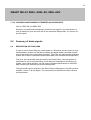
IMPORTANT INSTRUCTIONS .......................................................4
2.0
PRODUCT DESCRIPTION .............................................................4
3.0
BEFORE PLACING AN ORDER ....................................................5
4.0
3.1
You need to establish which version of Smart Relay is required ... 5
3.2
You need to establish what accessories are required ..................... 5
3.3
Mains adaptors need to be planned and acquired ........................... 5
3.4
You need to determine the installation location ............................... 6
3.5
Further information ............................................................................. 6
BEFORE INSTALLATION ..............................................................6
4.1
Installation of backup battery............................................................. 7
5.0
INSTALLATION ..............................................................................8
6.0
TERMINAL ASSIGNMENT.............................................................9
7.0
6.1
SREL and SREL.ZK ............................................................................. 9
6.2
SREL.ADV ............................................................................................ 9
6.3
Descriptions of connections in SREL, SREL.ZK and SREL .......... 10
PROGRAMMING AND CONFIGURATION ..................................11
7.1
Access control................................................................................... 12
7.2
Time zone control.............................................................................. 12
7.3
Overlay ............................................................................................... 12
7.4
Flip flop .............................................................................................. 12
7.5
Repeater ............................................................................................. 12
7.6
Time switchover ................................................................................ 12
7.7
OMRON............................................................................................... 13
7.7.1 Smart Relay in Omron mode .............................................................. 1
7.7.2 No audible programming acknowledgement signals..................... 15
7.7.3 External LED / external beeper......................................................... 15
7.7.4 Internal/external antennas ................................................................ 15
7.7.5 Number of extension modules ......................................................... 15
7.7.6 Pulse length ....................................................................................... 15
7.7.7 Interface ............................................................................................. 16
SMART RELAY SREL, SREL.ZK, SREL.ADV
7.7.8 Limited range ..................................................................................... 16
7.7.9 External beeper/ External LED ......................................................... 16
7.7.10 Logging unauthorised attempted access events ........................... 18
8.0
9.0
SUMMARY OF DIODE SIGNALS ................................................18
8.0
Description of functions ................................................................... 18
8.1
Wiegand interface (33 bit and 26 bit) ................................................. 1
8.2
Kaba Benzing, Siemens, Gantner Legic, Primion, Isgus interface 20
MAINTENANCE............................................................................21
9.1
Battery warning and battery replacement when the Battery
SREL.BAT is used ............................................................................. 21
9.2
Backup battery................................................................................... 21
10.0 TECHNICAL DATA FOR SREL ...................................................22
11.0 SMART RELAY 2 .........................................................................23
11.1
Smart Relay 2 versions ..................................................................... 23
11.2
Card reader versions in conjunction with srel2.............................. 24
12.0 DESCRIPTION OF THE SREL2 CONNECTIONS .......................25
13.0 TECHNICAL DATA FOR SREL2 .................................................26
14.0 PRODUCT DESCRIPTION ...........................................................28
14.1
ORDER CODE .................................................................................... 28
1.2
Higher-ranking locking level ............................................................ 28
15.0 WARNING.....................................................................................28
2.1
SAFETY .............................................................................................. 28
4
SMART RELAY SREL, SREL.ZK, SREL.ADV
1.0
Important instructions
Safety Instruction:
Warning: – The batteries used in this product may pose a fire or burn hazard if
handled incorrectly. Do not recharge, open or burn these batteries, or heat
them to over 100°C.
Specialist knowledge in door mechanics, door approvals, electronic system installation and the use of SimonsVoss software is required when installing a SimonsVoss
Smart Relay. This is why only trained specialists may install Smart Relay.
SimonsVoss Technologies AG accepts no liability for damage caused by incorrect installation.
Access through a door may be blocked due to defective or incorrectly installed Smart
Relays. SimonsVoss AG is not liable for consequences of incorrect installation,
such as blocked access to injured persons or those at risk, physical damage or any
other losses.
If Smart Relays are placed in storage for longer than a week, the backup battery is to
be removed.
Smart Relays must be installed in compliance with ESD (electrostatic discharge)
guidelines. You should particularly ensure that you do not touch circuit boards and
their integrated circuits.
In the event of doubt, original German language version applies.
2.0
Product Description
The SimonsVoss Smart Relay is an electronic switch which can be activated with a
SimonsVoss ID transponder. The authorisation for transponders which are permitted
to operate Smart Relay can be configured using the SimonsVoss software. Smart Relay thus fulfils the function of an access control reader.
5
SMART RELAY SREL, SREL.ZK, SREL.ADV
3.0
Before placing an order
3.1
YOU NEED TO ESTABLISH WHICH VERSION OF SMART RELAY IS REQUIRED
Smart Relay Basic version:
Order code: SREL
This relay provides a simple yes/no authorisation for a maximum of 8,184
different transponders.
Smart Relay Plus version with access event logging and time zones:
Order code: SREL.ZK
Similar to the basic version, but with the option of separately connectable access
event logging for the last 1,024 accesses (firmware version 4.0.01.15 and higher)
with date and time, or day – time zones for up to five user groups and automatic
locking and unlocking.
Smart Relay Advanced version:
Order code: SREL.ADV
Similar to the Plus version but with the following additional functions:
Connection for external module via a three-wire bus
Connection to an external antenna
Connections for serial ports to external time-and-attendance terminals
or access control readers
Connection for external LED or buzzer
See also 11.0 New Smart Relay 2 & card readers!
3.2
3.3
YOU NEED TO ESTABLISH WHAT ACCESSORIES ARE REQUIRED
1.
External antenna for unfavourable reception conditions
Order code: SREL.AV
2.
Batteries only for SREL, SREL.ZK and SREL.ADV for installations where
these products are operated without a mains power supply:
Order code: SREL.BAT
3.
Optional extension modules (e.g. Smart output module)
MAINS ADAPTORS NEED TO BE PLANNED AND ACQUIRED
These mains adapters are required for all Smart Relays which are not to be batteryoperated. The mains adapter should be limited to a maximum power of 15 watt and is
able to deliver a voltage of 12 V AC or 5 to 24 V DC with a current of 100 mA
.
6
SMART RELAY SREL, SREL.ZK, SREL.ADV
Warning! Do not use switching power supplies near Smart Relays. All mains adaptors
are to be provided by the customer; they cannot be acquired from SimonsVoss.
3.4
YOU NEED TO DETERMINE THE INSTALLATION LOCATION
The transponder transmission range for Smart Relay (read range) is a max. of 1.5 m,
but may be reduced in metallic environments, particularly in magnetic fields or where
there is aluminium.
Ideally, you should perform a read range test with an authorised transponder and a
battery-operated Smart Relay.
3.5
4.0
FURTHER INFORMATION
-
All cabling used to connect Smart Relay should be type IY(ST)Y ....x0.6 twisted pair, shielded cable - and cables should not exceed 100 m in length.
Power losses should be taken into account when dimensioning the power
supply.
-
The technical data regarding inputs and outputs are to be taken into account
(see Technical Data).
-
All cabling must be installed and connected as per VDE regulations (VDE =
German Association of Electro-technology, Electronics & Information Technology).
Before installation
Unpack Smart Relay and check for any damage.
Connect Smart Relay to a power supply or a battery.
If Smart Relay is to be operated via a mains adapter, insert the backup battery
in the designated holder (see Installation of backup battery).
Check that Smart Relay functions with a transponder in its as-delivered condition.
Remove the housing if you install in a flush-fitted masonry box.
If mounted on the surface, the base plate can be used as a template for the
drill holes (6 mm).
7
SMART RELAY SREL, SREL.ZK, SREL.ADV
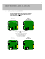
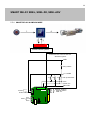
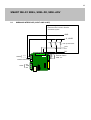
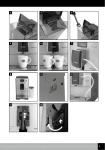
INSTALLATION OF BACKUP BATTERY
Backup
Batterie
einsetzen,
das Smart
mit
Only
use thenur
backup
battery ifwenn
the Smart
Relay isRelais
powered
use
this
battery
if
the
Smart
via
a
mains
adapter.
Do
not
Netzteil betrieben wird, bei Betrieb mit SREL.BAT diese
Relay is powered
by SREL.BAT.
Batterie
nicht einsetzen!
SREL
und SREL.ZK
+/~
-/~
C
A
B
+V
F3
F2
F1
SREL.ADV
BN
WH
GN
GY
YL
+
Batterie(included
InsertBackup
backup battery
supply package)
into the
(iminLieferumfang
enthalten)
holder.
POSITIVE
POLE
in die Halterung einführen
FACING NACH
UPWARDS!
PLUSPOL
OBEN
SREL
und SREL.ZK
SREL.ADV
+/~
-/~
C
A
B
+V
F3
F2
F1
4.1
+
BN
WH
GN
GY
YL
+
8
SMART RELAY SREL, SREL.ZK, SREL.ADV
5.0
Installation
Switch off the power supply (disconnect the plug or battery if necessary).
Connect all cables to their designated terminals on the Smart Relay (see Terminal Assignment on the next page).
It is essential to ensure the polarity is correct if you connect a DC mains
adapter.
You will achieve the largest reader range possible if the Smart Relay antennas
are aligned in parallel to that of the transponder.
Switch on the power supply (connect the plug or battery if required).
Check that Smart Relay functions with a transponder in its as-delivered condition.
Programme Smart Relay with the SimonsVoss software (we recommend software versions LDB. 1.50a or higher, or LSM 2.2 or higher).
Check that Smart Relay functions again using a newly authorised transponder.
9
SMART RELAY SREL, SREL.ZK, SREL.ADV
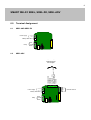
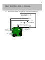
6.0
Terminal Assignment
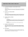
6.1
SREL AND SREL.ZK
Power supply
Netzteil
{ +- // ~~
Battery SREL.BAT
Batterie
SREL.BAT
Relais
Relay
SREL.ADV
Externe
EinExternal
inputs
und
and outputs
Ausgänge
1 RS 485-COM
2 RS 485-A
3 RS 485-B
4 + Vaux (3...5 V)
5 LED / Buzzer / Input 1 / CLS
6 Seriell 1 / Input 2
7 Seriell 2
6.2
{
NC
COM
NO
+/~
Power supply
Netzteil {
-/~
Batterie
SREL.BAT
Battery SREL.BAT
Relais
Relay
{
NC
COM
NO
Brown
White
Green
Grey
Yellow
}
Externe
Antenne
External antenna
SREL.AV
10
SMART RELAY SREL, SREL.ZK, SREL.ADV
6.3
DESCRIPTIONS OF CONNECTIONS IN SREL, SREL.ZK AND SREL
Name
Symbol Description
Mains adapter
+/~
Either positive pole when connected to a direct current
(5 to 24 V DC) or one of the two alternating current connections (12 V AC)
Mains adapter
-/~
Either negative pole when connected to a direct current
(5 to 24 V DC) or the second alternating current connection
(12 V AC)
Battery
Plug-in connector for a battery (when operated without a
mains adapter)
Battery order code, including plug connector: SREL.BAT
Relay NC
Normally closed contact in the relay changeover contact. This
contact is closed against Relay COM when not connected
Relay COM
Common contact in the relay changeover contact. This contact
is wired either against an NC relay (break contact) or against a
NO relay (closing contact)
NO relay
Normally open contact in the relay changeover contact. This
contact is closed against Relay COM when not connected
External antennas
Connection for colour-coded cables in an external
antenna (Order code: SREL.AV)
Brown
White
Green
Grey
Yellow
Brown
White
Green
Grey
Yellow
BN
WH
GN
GY
YL
RS-485COM
RS-485A
RS-485B
C
A
B
Bus connection for external modules
+ Vaux
+V
Type 3.0 - 5.0V +/- 0.5V for external LED or buzzer, max. 10mA
LED / buzzer / Input 1 F3
/ CLS
Serial 1 / Input 2
F2
Multi-function connection
Serial 2
Multi-function connection
F1
Multi-function connection
11
SMART RELAY SREL, SREL.ZK, SREL.ADV
7.0
Programming and configuration
If Smart Relay is selected as the lock type in the SimonsVoss software (LDB Version
1.40 or higher, or LSM 2.1 or higher), the following configuration options are available:
12
SMART RELAY SREL, SREL.ZK, SREL.ADV
7.1
ACCESS CONTROL
Only possible in SREL.ZK und SREL.ADV versions. The 1,024 most recent transponder transactions are logged with the date and time.
7.2
TIME ZONE CONTROL
Only possible in SREL.ZK und SREL.ADV versions. A time zone plan can be uploaded and the transponders are approved or blocked according to their time zone
group.
7.3
OVERLAY
Replacement transponders can overwrite their corresponding original transponders.
The original transponder is blocked once the replacement transponder is used for the
first time.
7.4
FLIP FLOP
Pulse mode (default setting) is switched off and the pulse duration no longer plays a
role. When flip flop mode is activated, Smart Relay changes its status from on to off
or vice versa each time it is activated using a transponder. This mode is ideal for
switching lights, machines and other systems on and off.
Where applicable, you should ensure that mains adapters and electric strikes
are suitable for continuous current operation in such an installation.
7.5
REPEATER
Smart Relay receives a transponder signal, which it amplifies and forwards. This function allows Smart Relay to be used to bridge longer radio transmission paths. The distance to the next Smart Relay can be up to 2 m.
7.6
TIME SWITCHOVER
For SREL.ZK and SREL.ADV only: when the time switchover is activated, a time
zone plan needs to be uploaded which allows the Smart Relay to remain released
during the indicated times (in Group 5). During the day, the door can be used freely
while only a transponder will open the door at night.
You should ensure that mains adapters and electric strikes are suitable for continuous current operation in such an installation.
13
SMART RELAY SREL, SREL.ZK, SREL.ADV
If you select time switchover, the following options are available to you in the 'Timecontrolled switchover' box (several options can be selected):
1.
Manual lock
The door does not lock automatically after the pre-set point in time until an
authorised transponder makes a booking after this time.
2.
Automatic lock (basic setting)
The door is locked precisely at the point in time specified in the time zone
plan.
3.
Manual unlocking (basic setting)
The door is not unlocked automatically after the pre-set point in time until an
authorised transponder makes a booking after this time.
4.
Automatic unlocking
The door is not normally opened after the pre-set point in time, but when the
first transponder activates it. If you specifically want the door to unlock automatically at the pre-set time, then select this option.
5.
Transponder, active
- Always
Normally, a transponder cannot be used during the release interval. However,
if you wish the door to be locked whenever required (when everybody has left
the building, for example), select this option.
- Only if locked
In this operating mode, the transponder is not operative during the unlocked
interval.
7.7
OMRON
Only for SREL.ADV: many access control and time-and-attendance systems feature
serial interfaces to connect card readers. A Smart Relay can also be connected via
these interfaces, thus also allowing you to use SimonsVoss transponders in thirdparty systems.
Select this option on both the Smart Relay and the cylinder if you wish the Smart Relay to transmit transponder data to a third-party system and a remote opening command to be sent from Smart Relay to a cylinder after clearance by the third-party system.
Set the type of external system under 'Interfaces'. The following options are available:
14
SMART RELAY SREL, SREL.ZK, SREL.ADV
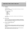
7.7.1
SMART RELAY IN OMRON MODE
Authorised?
Access control system
ExExternal
ternes Zutrittskontrolloder
access control or time-andZeiterfassungssystem
attendance system
GND
Freischalt
Relais
Relay release
+ 5..12VDC
1K
1K
1K
PuPull
ll Upup
Widerstände
resistances
CLS
Clock / D1
Data / D0
Netzteil
{ +- // ~~
F3 F2 F1
Batterie SREL.BAT
Relais
{
NC
COM
NO
Brown
White
Green
Grey
Yellow
}
Externe
ExternalAntenne
antenna
SREL.AV
SREL..AV
15
SMART RELAY SREL, SREL.ZK, SREL.ADV
7.7.2
NO AUDIBLE PROGRAMMING ACKNOWLEDGEMENT SIGNALS
SREL.ADV only
You should check this field if you do not want audible programming acknowledgement
signals to be emitted from a connected buzzer or beeper while you are programming
Smart Relay.
7.7.3
EXTERNAL LED / EXTERNAL BEEPER
SREL.ADV only
This indicates which external component group is connected. In flip flop mode, Smart
Relay emits a permanent signal when switched on if there is an external LED; in the
case of a beeper, an audible signal is only emitted when there is a change of status.
7.7.4
INTERNAL/EXTERNAL ANTENNAS
SREL.ADV only
7.7.5
-
Auto-detection
If an external antenna is connected, this is the one which is used. Smart Relay
switches off the internal antenna in such cases. If no external antenna is connected (standard case), Smart Relay functions with the internal antenna.
-
Both active
Smart Relay is able to use both antennas to verify transponder bookings.
NUMBER OF EXTENSION MODULES
This is where you indicate the number of external modules connected to the Smart
Relay. These modules are connected to the terminals RS-485 COM, RS-485 A and
RS-485 B. You will find more detailed information in the documentation for individual
modules.
7.7.6
PULSE LENGTH
This is where you indicate the number of seconds for the switch pulse duration. The
value can be set at 0.1 to 25.5 seconds. If you enter 3 seconds, for example, an electric strike is released for 3 seconds before it locks again.
16
SMART RELAY SREL, SREL.ZK, SREL.ADV
7.7.7
INTERFACE
For SREL.ADV only
You can enter the type of card reader here which the Smart Relay is to simulate for
operation as a serial interface.
The following options are available:
• Wiegand, 33 bit
• Wiegand, 26 bit
• Primion
• Siemens
• Kaba Benzing
• Gantner Legic
• Isgus
You can find the relevant information on cabling in the section "Smart Relay as a
serial interface."
7.7.8
LIMITED RANGE
If you select this option, the reader range from the transponder Æ Smart Relay is reduced from 1.5 m to about 0.4 m. This option can be used when several Smart Relays are in close proximity to one another and individual transponders are authorised
for use on several Smart Relays, for example.
7.7.9
EXTERNAL BEEPER/ EXTERNAL LED
For SREL.ADV only
Smart Relay is normally configured for connection to an LED. If you wish to connect a
beeper or buzzer as an external signalling device, check this option. This will allow
the beeper or buzzer to be used instead of the LED to emit an audible acknowledgement signal.
The wiring diagram may look as follows when the connected components require a maximum current of less than 10 mA at 3 V DC.
17
SMART RELAY SREL, SREL.ZK, SREL.ADV
Evtl. Widerstand
zur
Poss. resistance
to power
Leistungsbegrenzun
limitation.
The V+ output g.
Dermax.
Ausgang
V+atliefert
supplies
10 mA
max. 10 mA bei 3VDC
3 V DC
Entweder Buzzer oder LED
Either buzzer or LED
+/~
Netzteil {
-/~
Brown
White
Green
Grey
Yellow
V+ F3
Batterie SREL.BAT
Relais
{
}
External Antenne
antenna
Externe
SREL..AV
SREL.AV
NC
COM
NO
If the current for the external component is greater than 10 mA, this component
must be fed via an external power supply.
If this is the case, you should install the connection as follows:
Ext. Netzteil
GND
Evtl. Widerstand zur
Poss.
resistance to power
Leistungsbegrenzung.
limitation.
The F3
Der
Ausgang
F3output
verträgt
tolerates
max.
50
mA.
max. 50 mA
Maximal + 24V
EEither
ntweder
Buzzer
oder LED
buzzer
or LED
+/~
Netzteil {
-/~
F3
Batterie SREL.BAT
Relais
{
NC
COM
NO
Brown
White
Green
Grey
Yellow
}
Externe
ExternalAntenne
antenna
SRSREL..AV
EL.AV
18
SMART RELAY SREL, SREL.ZK, SREL.ADV
7.7.10 LOGGING UNAUTHORISED ATTEMPTED ACCESS EVENTS
Only for SREL.ZK und SREL.ADV
Normally, only authorised transponder operations are logged. If you also wish to record an attempt to open the door with a non-authorised transponder, you need to select this option.
8.0
Summary of diode signals
8.0
DESCRIPTION OF FUNCTIONS
In order to use a Smart Relay as a card reader in a third-party access control or timeand-attendance system, the hardware (cabling and signal emitter) and data formats
must match those of the card reader precisely. This is the only way that the third-party
system will be able to understand and evaluate data from SimonsVoss transponders.
First of all, the transponder data are read by the Smart Relay. If the transponder is
authorised for use in the Smart Relay, these data are transmitted to the third-party
system via the serial interface. You will receive detailed specifications for individual
data formats from SimonsVoss Product Management.
The right reader type is selected in the Smart Relay configuration in the SimonsVoss
software, version 1.40 and higher. The connections for the different reader variants
are listed below.
19
SMART RELAY SREL, SREL.ZK, SREL.ADV
8.1
WIEGAND INTERFACE (33 BIT AND 26 BIT)
Externes
Zutrittskontrolloder
External
access
control or timeand
attendance-system
Zeiterfassungssystem
GND
+ 5..12VDC
1K
1K
1K
Pull
Pull Up
up Widerstände
resistances
CLS
D1
D0
Netzteil
{ +- // ~~
F2 F1
Batterie SREL.BAT
Relais
{
NC
COM
NO
Brown
White
Green
Grey
Yellow
}
EExternal
xterne antenna
Antenne
SREL..AV
SREL.AV
20
SMART RELAY SREL, SREL.ZK, SREL.ADV
8.2
KABA BENZING, SIEMENS, GANTNER LEGIC, PRIMION, ISGUS INTERFACE
Externes Zutrittskontroll- oder
External access control or timeand
Zeiterfassungssystem
attendance-system
GND
+ 5..12VDC
1K
1K
1K
Pull Up Widerstände
Pull up resistances
CLS
Clock
Data
+/~
Netzteil {
-/~
F2 F1
Batterie SREL.BAT
Relais
{
NC
COM
NO
Brown
White
Green
Grey
Yellow
}
EExternal
xterne Antenne
antenna
SSREL..AV
REL.AV
21
SMART RELAY SREL, SREL.ZK, SREL.ADV
9.0
Maintenance
9.1
BATTERY WARNING AND BATTERY REPLACEMENT WHEN THE BATTERY
SREL.BAT IS USED
A Smart Relay can emit a battery warning as follows when the battery capacity is depleted:
SREL, SREL.ZK, SREL.ADV
Inside LED flashes 8x each time a transponder is used and before the relay
switches.
This LED should be visible from the outside in the case of battery-powered
operation.
SREL.ADV only
External LED flashes 8x or external buzzer beeps 8x each time a transponder
is used.
Around another 100 transactions are possible after a battery warning; the battery should thus be replaced as soon as possible.
9.2
BACKUP BATTERY
A discharged backup battery may lead to the internal clock stopping in Smart Relay
types SREL.ZK and SREL.ADV. We therefore recommend checking the time on the
clock at regular intervals. A backup battery will last for about ten years if the power
supply to the Smart Relay is not interrupted. If Smart Relay draws on the backup battery at regular intervals due to frequent power failures, this battery should be replaced
on a periodical basis.
If Smart Relay is powered by a battery (SREL.BAT), the backup battery must not be
used.
22
SMART RELAY SREL, SREL.ZK, SREL.ADV
10.0 Technical data for SREL
Housing made of black plastic: dimensions l x w x h
72 x 57 x 25.5 mm
Protection rating
IP20, not tested for outside use
Temperature
When operating: -22ºC to 55ºC
In storage: 0ºC to 40ºC
Humidity
< 95% without condensation
Circuit board dimensions l x w x h
50 x 50 x 14 mm
Mains voltage
12 V AC or 5-24 V DC
(no reverse polarity protection)
Power limitation
Mains adapter must be limited to 15 VA
Standby current
< 5 mA
Max. current
< 100 mA
Pulse duration programmable
0.1 to 25.5 seconds
Output relay type
Changeover contact
Output relay continuous current
Max. 1.0 A
Output relay switch-on current
Max. 2.0 A
Output relay switching voltage
Max. 24 V
Output relay switching power
106 operations at 30 V A
Multi-function connections F1, F2, F3
Max. 24 V DC, max. 50 mA
Vibrations:
15 G for 11 ms,
6 shocks as per IEC 68-2-27
Not approved for use when subject to permanent vibrations
23
SMART RELAY SREL, SREL.ZK, SREL.ADV
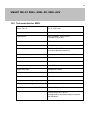
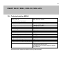
11.0 Smart Relay 2
11.1
SMART RELAY 2 VERSIONS
SREL2.G2.W: The SREL2 is basically used with transponders, i.e. as purely "active"
components. There is also the option of using a Compact Reader and operating the
SREL with Mifare Classic/DERFire® cards.
This relay provides a simple yes/no authorisation for a maximum of 64,000 different
transponders.
SREL2.G2.W.WP: As described above, but with a waterproof design.
You must seal the bushing yourself under your own responsibility. It is recommended
to use suitable materials such as silicon or another resistant sealing material. The
housing features an IP65 design.
SREL2.ZK.G2.W: The same as the basic version, but with the option of separately
connectable access event logging for the last 1,024 accesses with date and time, or
day – time zones for up to 100 user groups and automatic locking and unlocking
(time-controlled switchover). This version can also be used as a gateway in a virtual
network.
SREL2.ZK.G2.W.WP: As described above, but with a waterproof design.
You must seal the bushing yourself under your own responsibility. It is recommended
to use suitable materials such as silicon or another resistant sealing material. The
housing features an IP65 design.
SREL2.ZK.MH.G2.W: As the ZK version above. Two external card readers
(SC.M.E.G2) and an internal card reader (SC.M.I.G2) can be connected to this version. Mifare Classic/DERFire® cards can be used with this particular SREL2.
SREL2.ZK.MH.G2.W.WP: As described above, but with a waterproof design.
You must seal the bushing yourself under your own responsibility. It is recommended
to use suitable materials such as silicon or another resistant sealing material. The
housing features an IP65 design.
24
SMART RELAY SREL, SREL.ZK, SREL.ADV
Use of the backup battery (CR1220 Sony) is described in Section 4.1.
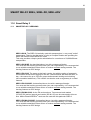
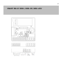
11.2
CARD READER VERSIONS IN CONJUNCTION WITH SREL2
The SC components can be operated with Mifare Classic® or Mifare DESFire®.
SC.M.E.G2.W: Smart Card Mifare External (external card reader) G2 (Generation 2)
W (white housing)
A maximum of two external card readers (SC.M.E.G2.W) and one internal card
reader (SC.M.I.G2) can be connected to an SREL2.ZK.MH.G2.W or
SREL2.ZK.MH.G2.W.WP. If two external card readers are connected to an SREL2,
then a dip switch placed at the "on" position must be connected to one external card
reader. The dip switch is found on the right-hand side beneath the 26-pin plug connector on the card reader (see diagram).
The cabling type used to wire components should be CAT5 (FTP) or a higher quality.
Shielded control cabling may also be used. Cable length: max. 10 m. If the cable line
length is > 3 m for the external card reader, its own power supply and its own wiring
should be installed
SC.M.E.G2.W.WP: As above, but the waterproof design of card readers is supplied
with a cable about 1 m long pre-attached ready for use.
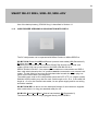
SC.M.I.G2: Smart Card Mifare I (internal card reader) G2 (Generation 2)
The internal card reader is simply plugged directly into the SREL2.
25
SMART RELAY SREL, SREL.ZK, SREL.ADV
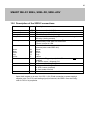
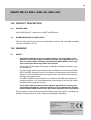
12.0 Description of the SREL2 connections
Name
Symbol Description
Mains adapter
Mains adapter
Battery
Relay COM
+ DC
- DC
NO relay
External antennas
Brown
White
Green
Grey
Yellow
Functions connection
BN
WH
GN
GY
YL
F1
F2
F3
SVB
Direct current 9 to 24 V DC
Direct current 9 to 24 V DC
CR1220, Sony – Backup battery
Common contact in the relay. This contact is wired against
NO relay (closing contact)
Normally open contact in the relay. This contact is closed
against Relay COM when not connected
Can be inverted in LSM
Connection for colour-coded wires in an external
antenna (order code SREL.AV)
Brown
White
Green
Grey
Yellow
Å Input ext. Trigger input (3-24 V DC ext. contact must be
isolated)
Æ Omron output / Wiegand CLS
Æ Omron data / Wiegand D0
Æ Omron CLK / Wiegand D1
Æ LED / buzzer (external)
Æ Card reader line link
SimonsVoss bus - card reader line link
Open drain outputs up to max. 24 V DC / 0.5 A. Earth connection to power supply's
negative pole. If a CLS (card loading signal) is featured, the SREL2 must be configured for CLS in its properties.
26
SMART RELAY SREL, SREL.ZK, SREL.ADV
13.0 Technical data for SREL2
Housing made of white plastic: dimensions l x w x h
Semi-transparent base plate
Protection rating
Temperature
Humidity
Circuit board dimensions l x w x h
Mains voltage
Power limitation
Standby current
Max. current
Pulse duration programmable
Output relay type
Output relay continuous current
Output relay switch-on current
Output relay switching voltage
Output relay switching power
Multi-function connections F1, F2, F3
Vibrations:
about 78 x 78 x 19 mm
See note in 11.0
When operating: -22ºC to 55ºC
In storage: 0ºC to 40ºC
< 95% without condensation
about 50 x 50 x 14 mm
9-24 V DC
Mains adapter must be limited to 15 VA
< 100 mA
< 300 mA
1 to 25.5 seconds
Closing contact
Max. 1.0 A
Max. 2.0 A
Max. 24 V
106 operations at 30 V A
Max. 24 V DC, max. 50 mA
15 G for 11 ms,
6 shocks as per IEC 68-2-27
Not approved for use when subject to permanent vibrations
All work must be carried out with the unit fully disconnected!
27
SMART RELAY SREL, SREL.ZK, SREL.ADV
28
SMART RELAY SREL, SREL.ZK, SREL.ADV
14.0 PRODUCT DESCRIPTION
14.1
ORDER CODE
WN.CN.UR.SCHALT, referred to as INPUT NODE below.
1.2
HIGHER-RANKING LOCKING LEVEL
The text field placed under Level 2 automatically receives the "standard" template.
The text is indented 1.25 cm.
15.0 WARNING
2.1
SAFETY
−
Specialist knowledge in access control systems, door mechanics, door
approvals, electronic system installation and the use of SimonsVoss software is required when installing a SimonsVoss INPUT NODE. This is why
only trained specialists may install this terminal.
−
SimonsVoss Technologies AG accepts no liability for damage caused by incorrect installation.
−
Access through a door may be blocked due to defective or incorrectly installed
INPUT NODES. SimonsVoss AG is not liable for consequences of incorrect installation, such as blocked access to injured persons or those at risk, physical
damage or any other losses.
−
The INPUT NODE must be installed in compliance with ESD (electrostatic discharge) guidelines. You should particularly ensure that you do not touch circuit
boards and their integrated circuits.
−
Those fitted with electronic medical implants (pacemakers, hearing aids
and similar) must keep a minimum distance of 30 cm between the implant
and the INPUT NODE and are to be specifically informed of this precaution.
As a precaution, people who have implants should consult their doctor regarding any
possible hazards caused by radio component assemblies (868 MHz).