1
USRobotics Controllerless
Command Reference
R46.2020.00
rev 1 12/09
USRobotics
Command Reference
Contents
Introduction . . . . . . . . . . . . . . . . . . . . . . . . . . . . . . . . . . . . . . . . . . . . 1
Overview . . . . . . . . . . . . . . . . . . . . . . . . . . . . . . . . . . . . . . . . . . . . . . . . . . . . . . . . . . . . . . 1
Command Syntax . . . . . . . . . . . . . . . . . . . . . . . . . . . . . . . . . . . . . . . . . . . . . . . . . . . . . 1
Command Descriptions . . . . . . . . . . . . . . . . . . . . . . . . . . . . . . . . . . . . . . . . . . . . . . . . . 1
Syntax and Procedures. . . . . . . . . . . . . . . . . . . . . . . . . . . . . . . . . . . . 3
Alphabet . . . . . . . . . . . . . . . . . . . . . . . . . . . . . . . . . . . . . . . . . . . . . . . . . . . . .
DTE Commands Lines . . . . . . . . . . . . . . . . . . . . . . . . . . . . . . . . . . . . . . . . . . . .
Command Line General Format . . . . . . . . . . . . . . . . . . . . . . . . . . . . . . . . . . .
Command Line Editing . . . . . . . . . . . . . . . . . . . . . . . . . . . . . . . . . . . . . . . . .
Command Line Echo . . . . . . . . . . . . . . . . . . . . . . . . . . . . . . . . . . . . . . . . . .
Repeating a Command Line . . . . . . . . . . . . . . . . . . . . . . . . . . . . . . . . . . . . .
Types of DTE Commands . . . . . . . . . . . . . . . . . . . . . . . . . . . . . . . . . . . . . . .
Basic Syntax Commands . . . . . . . . . . . . . . . . . . . . . . . . . . . . . . . . . . . . . . . . . .
Basic Syntax Command Format. . . . . . . . . . . . . . . . . . . . . . . . . . . . . . . . . . .
S-Parameters . . . . . . . . . . . . . . . . . . . . . . . . . . . . . . . . . . . . . . . . . . . . . . .
Extended Syntax Commands . . . . . . . . . . . . . . . . . . . . . . . . . . . . . . . . . . . . . . .
Command Naming Rules . . . . . . . . . . . . . . . . . . . . . . . . . . . . . . . . . . . . . . .
Values . . . . . . . . . . . . . . . . . . . . . . . . . . . . . . . . . . . . . . . . . . . . . . . . . . . .
Numeric Constants . . . . . . . . . . . . . . . . . . . . . . . . . . . . . . . . . . . . . .
String Constants . . . . . . . . . . . . . . . . . . . . . . . . . . . . . . . . . . . . . . .
Compound Values . . . . . . . . . . . . . . . . . . . . . . . . . . . . . . . . . . . . . . . . . . . .
Action Commands . . . . . . . . . . . . . . . . . . . . . . . . . . . . . . . . . . . . . . . . . . . .
Action Execution Command Syntax . . . . . . . . . . . . . . . . . . . . . . . . . .
Action Test Command Syntax . . . . . . . . . . . . . . . . . . . . . . . . . . . . . .
Parameter Commands . . . . . . . . . . . . . . . . . . . . . . . . . . . . . . . . . . . . . . . . .
Parameter Types . . . . . . . . . . . . . . . . . . . . . . . . . . . . . . . . . . . . . . .
Parameter Set Command Syntax . . . . . . . . . . . . . . . . . . . . . . . . . . . .
Parameter Read Command Syntax . . . . . . . . . . . . . . . . . . . . . . . . . . .
Parameter Test Command Syntax . . . . . . . . . . . . . . . . . . . . . . . . . . .
Additional Syntax Rules . . . . . . . . . . . . . . . . . . . . . . . . . . . . . . . . . . . . . . . .
Concatenating Commands after Extended Syntax Commands . . . . . . . .
Concatenating Commands after Basic Format Commands . . . . . . . . . . .
Issuing Commands . . . . . . . . . . . . . . . . . . . . . . . . . . . . . . . . . . . . . . . . . . . . . .
Executing Commands . . . . . . . . . . . . . . . . . . . . . . . . . . . . . . . . . . . . . . . . . . . .
Aborting Commands . . . . . . . . . . . . . . . . . . . . . . . . . . . . . . . . . . . . . . . . . .
Handling of Invalid Numbers and S-Parameter Values . . . . . . . . . . . . . . . . . . .
Modem Responses. . . . . . . . . . . . . . . . . . . . . . . . . . . . . . . . . . . . . . . . . . . . . . .
Responses . . . . . . . . . . . . . . . . . . . . . . . . . . . . . . . . . . . . . . . . . . . . . . . . .
Information Text. . . . . . . . . . . . . . . . . . . . . . . . . . . . . . . . . . . . . . . .
Result Code Parts . . . . . . . . . . . . . . . . . . . . . . . . . . . . . . . . . . . . . . .
Result Code Types . . . . . . . . . . . . . . . . . . . . . . . . . . . . . . . . . . . . . .
Extended Syntax Result Codes . . . . . . . . . . . . . . . . . . . . . . . . . . . . . . . . . . .
Fax Modes . . . . . . . . . . . . . . . . . . . . . . . . . . . . . . . . . . . . . . . . . . . .
Range of Values . . . . . . . . . . . . . . . . . . . . . . . . . . . . . . . . . . . . . . . .
Compound Range of Values . . . . . . . . . . . . . . . . . . . . . . . . . . . . . . . .
....
....
....
....
....
....
....
....
....
....
....
....
....
....
....
....
....
....
....
....
....
....
....
....
....
....
....
....
....
....
....
....
....
....
....
....
....
....
....
....
....
....
....
....
....
....
....
....
....
....
....
....
....
....
....
....
....
....
....
....
....
....
....
....
....
....
....
....
....
....
....
....
....
....
....
....
....
....
....
....
.3
.3
.3
.4
.4
.4
.4
.5
.5
.5
.6
.6
.6
.7
.7
.7
.8
.8
.8
.9
.9
.9
10
10
10
10
10
10
11
11
11
12
12
12
13
13
13
14
14
15
Data Command Set . . . . . . . . . . . . . . . . . . . . . . . . . . . . . . . . . . . . . . 17
Command Guidelines. . . . . . . . . . . . . . . . . .
Escape Code Sequence. . . . . . . . . . . . . .
Data Commands . . . . . . . . . . . . . . . . . . . . .
Generic Modem Control . . . . . . . . . . . . .
Z - Reset to Default Configuration
.
.
.
.
.
.
.
.
.
.
.
.
.
.
.
.
.
.
.
.
.
.
.
.
.
.
.
.
.
.
.
.
.
.
.
.
.
.
.
.
.
.
.
.
.
.
.
.
.
.
.
.
.
.
.
.
.
.
.
.
.
.
.
.
.
.
.
.
.
.
.
.
.
.
.
.
.
.
.
.
.
.
.
.
.
.
.
.
.
.
.
.
.
.
.
.
.
.
.
.
.
.
.
.
.
.
.
.
.
.
.
.
.
.
.
.
.
.
.
.
.
.
.
.
.
.
.
.
.
.
.
.
.
.
.
.
.
.
.
.
.
.
.
.
.
.
.
.
.
.
.
.
.
.
.
.
.
.
.
.
.
.
.
.
.
.
.
.
.
.
.
.
.
.
.
17
17
17
17
17
iii
USRobotics
Command Reference
+FCLASS - Select Active Service Class . . . . . . . . . . . . . . . . . . . . . . . . . . . .
Defined Values. . . . . . . . . . . . . . . . . . . . . . . . . . . . . . . . . . . . . . . . . . . . .
+VCID - Caller ID (CID) . . . . . . . . . . . . . . . . . . . . . . . . . . . . . . . . . . . . . .
+VRID - Report Retieved Caller ID (CID) . . . . . . . . . . . . . . . . . . . . . . . . . .
\N - Operating Mode . . . . . . . . . . . . . . . . . . . . . . . . . . . . . . . . . . . . . . . . .
&F - Set to Factory-Defined Configuration . . . . . . . . . . . . . . . . . . . . . . . . . .
&T - Local Analog Loopback Test . . . . . . . . . . . . . . . . . . . . . . . . . . . . . . . .
I - Request Identification Information . . . . . . . . . . . . . . . . . . . . . . . . . . . . .
+GMI - Request Manufacturer Identification . . . . . . . . . . . . . . . . . . . . . . . .
+GMM - Request Model Identification . . . . . . . . . . . . . . . . . . . . . . . . . . . . .
+GMR - Request Revision Identification . . . . . . . . . . . . . . . . . . . . . . . . . . .
+GSN - Request Product Serial Number Identification. . . . . . . . . . . . . . . . . .
+GOI - Request Global Object Identification . . . . . . . . . . . . . . . . . . . . . . . .
+GCAP - Request Complete Capabilities List . . . . . . . . . . . . . . . . . . . . . . . .
+GCI - Country of Installation . . . . . . . . . . . . . . . . . . . . . . . . . . . . . . . . . .
DTE-Modem interface Commands . . . . . . . . . . . . . . . . . . . . . . . . . . . . . . . . . . . . .
E - Command Echo . . . . . . . . . . . . . . . . . . . . . . . . . . . . . . . . . . . . . . . . . .
Q - Quiet Results Codes Control . . . . . . . . . . . . . . . . . . . . . . . . . . . . . . . . .
V - Result Code Form . . . . . . . . . . . . . . . . . . . . . . . . . . . . . . . . . . . . . . . .
W - Connect Message Control . . . . . . . . . . . . . . . . . . . . . . . . . . . . . . . . . .
X - Extended Result Codes . . . . . . . . . . . . . . . . . . . . . . . . . . . . . . . . . . . .
&C - RLSD Behavior . . . . . . . . . . . . . . . . . . . . . . . . . . . . . . . . . . . . . . . . .
&D - DTR Behavior . . . . . . . . . . . . . . . . . . . . . . . . . . . . . . . . . . . . . . . . . .
&K - Flow Control . . . . . . . . . . . . . . . . . . . . . . . . . . . . . . . . . . . . . . . . . . .
&M - Asynchronous/Synchronous Mode Selection . . . . . . . . . . . . . . . . . . . . .
&Q - Sync/Async Mode . . . . . . . . . . . . . . . . . . . . . . . . . . . . . . . . . . . . . . .
+IPR - Fixed DTE Rate . . . . . . . . . . . . . . . . . . . . . . . . . . . . . . . . . . . . . . .
+IFC - DTE-Modem Local Flow Control . . . . . . . . . . . . . . . . . . . . . . . . . . . .
+ILRR - DTE-Modem Local Rate Reporting . . . . . . . . . . . . . . . . . . . . . . . . .
Call Control. . . . . . . . . . . . . . . . . . . . . . . . . . . . . . . . . . . . . . . . . . . . . . . . . . . . .
D - Dial . . . . . . . . . . . . . . . . . . . . . . . . . . . . . . . . . . . . . . . . . . . . . . . . . .
T - Set Tone Dial Default . . . . . . . . . . . . . . . . . . . . . . . . . . . . . . . . . . . . . .
P - Set Pulse Dial Default . . . . . . . . . . . . . . . . . . . . . . . . . . . . . . . . . . . . .
A - Answer . . . . . . . . . . . . . . . . . . . . . . . . . . . . . . . . . . . . . . . . . . . . . . .
H - Disconnect (Hang-Up) . . . . . . . . . . . . . . . . . . . . . . . . . . . . . . . . . . . . .
O - Return to On-Line Data Mode . . . . . . . . . . . . . . . . . . . . . . . . . . . . . . . .
L - Speaker Volume . . . . . . . . . . . . . . . . . . . . . . . . . . . . . . . . . . . . . . . . .
M - Speaker Control . . . . . . . . . . . . . . . . . . . . . . . . . . . . . . . . . . . . . . . . .
&G - Select Guard Tone . . . . . . . . . . . . . . . . . . . . . . . . . . . . . . . . . . . . . .
&P - Select Pulse Dial Make/Break Ratio . . . . . . . . . . . . . . . . . . . . . . . . . . .
&V - Display Current Configuration and Stored Profile. . . . . . . . . . . . . . . . . .
&W - Store Current Configuration. . . . . . . . . . . . . . . . . . . . . . . . . . . . . . . .
*B - Display Blacklisted Numbers . . . . . . . . . . . . . . . . . . . . . . . . . . . . . . . .
*D - Display Delayed Numbers . . . . . . . . . . . . . . . . . . . . . . . . . . . . . . . . .
Modulation Control Commands . . . . . . . . . . . . . . . . . . . . . . . . . . . . . . . . . . . . . . .
+MS - Modulation Selection . . . . . . . . . . . . . . . . . . . . . . . . . . . . . . . . . . . .
Syntax . . . . . . . . . . . . . . . . . . . . . . . . . . . . . . . . . . . . . . . . . . . . . . . . . .
+MR - Modulation Reporting Control . . . . . . . . . . . . . . . . . . . . . . . . . . . . . .
%E - Enable/Disable Line Quality Monitor, Auto-Retrain, and
Auto-Rate Renegotiation . . . . . . . . . . . . . . . . . . . . . . . . . . . . . . . . . . . . . .
Error Control Commands . . . . . . . . . . . . . . . . . . . . . . . . . . . . . . . . . . . . . . . . . . .
+ES - Error Control and Synchronous Mode Selection . . . . . . . . . . . . . . . . . .
Reporting Supported Range of Parameter Values . . . . . . . . . . . . . . . . . . . . .
+EB - Break Handling in Error Control Operation . . . . . . . . . . . . . . . . . . . . .
+ESR - Selective Repeat . . . . . . . . . . . . . . . . . . . . . . . . . . . . . . . . . . . . . .
+EFCS - 32-bit Frame Check Sequence. . . . . . . . . . . . . . . . . . . . . . . . . . . .
+ER - Error Control Reporting . . . . . . . . . . . . . . . . . . . . . . . . . . . . . . . . . .
+ER: <type>. . . . . . . . . . . . . . . . . . . . . . . . . . . . . . . . . . . . . . . . . . . . . .
+ETBM - Call Termination Buffer Management . . . . . . . . . . . . . . . . . . . . . . .
....
....
....
....
....
....
....
....
....
....
....
....
....
....
....
....
....
....
....
....
....
....
....
....
....
....
....
....
....
....
....
....
....
....
....
....
....
....
....
....
....
....
....
....
....
....
....
....
18
18
19
19
20
21
21
21
22
23
23
23
24
24
24
25
25
26
26
27
27
32
33
34
34
34
35
36
37
38
38
40
40
41
41
42
42
43
43
44
44
45
45
46
46
46
46
49
.
.
.
.
.
.
.
.
.
.
50
51
51
53
53
54
54
55
55
56
.
.
.
.
.
.
.
.
.
.
.
.
.
.
.
.
.
.
.
.
.
.
.
.
.
.
.
.
.
.
iv
USRobotics
Command Reference
3.2.6 Data Compression Commands . . . . . . . . . . . . . . . . . . . . . . . . . . . . . . . . . . .
+DS - Data Compression . . . . . . . . . . . . . . . . . . . . . . . . . . . . . . . . . . . . .
+DS44 - V.44 Compression Select . . . . . . . . . . . . . . . . . . . . . . . . . . . . . . .
+DR - Data Compression Reporting . . . . . . . . . . . . . . . . . . . . . . . . . . . . . .
+DR: <type> Intermediate Result Code . . . . . . . . . . . . . . . . . . . . . . . . . . .
%C - Enable/Disable Data Compression . . . . . . . . . . . . . . . . . . . . . . . . . . .
N - Automode Enable . . . . . . . . . . . . . . . . . . . . . . . . . . . . . . . . . . . . . . . .
V.8/V.8bis Commands . . . . . . . . . . . . . . . . . . . . . . . . . . . . . . . . . . . . . . . . . . . . .
+A8E - V.8 and V.8bis Operation Controls . . . . . . . . . . . . . . . . . . . . . . . . . .
Synchronous Access Mode Commands . . . . . . . . . . . . . . . . . . . . . . . . . . . . . . . . . .
+ESA - Configure Synchronous Access Mode . . . . . . . . . . . . . . . . . . . . . . . .
+ITF - Transmit Flow Control Thresholds. . . . . . . . . . . . . . . . . . . . . . . . . . .
Diagnostic and Test Commands. . . . . . . . . . . . . . . . . . . . . . . . . . . . . . . . . . . . . . .
#UD - Last Call Status Report . . . . . . . . . . . . . . . . . . . . . . . . . . . . . . . . . .
Example Modem Response and Usage . . . . . . . . . . . . . . . . . . . . . . . . . . . . . . . . . .
%TT - PTT Test Command. . . . . . . . . . . . . . . . . . . . . . . . . . . . . . . . . . . . .
V.92 +P and -Q Commands . . . . . . . . . . . . . . . . . . . . . . . . . . . . . . . . . . . . . . . . . . . .
+PCW - Call Waiting Enable. . . . . . . . . . . . . . . . . . . . . . . . . . . . . . . . . . . .
+PMH - Modem-on-Hold Enable . . . . . . . . . . . . . . . . . . . . . . . . . . . . . . . . .
+PMHT - Modem-on-Hold Timer . . . . . . . . . . . . . . . . . . . . . . . . . . . . . . . . .
+PMHR - Initiate Modem-on-Hold. . . . . . . . . . . . . . . . . . . . . . . . . . . . . . . .
+PIG - PCM Upstream Ignore . . . . . . . . . . . . . . . . . . . . . . . . . . . . . . . . . .
+PMHF - V.92 Modem-on-Hold Hook Flash . . . . . . . . . . . . . . . . . . . . . . . . .
+PQC - V.92 Phase 1 and Phase 2 Control. . . . . . . . . . . . . . . . . . . . . . . . . .
+PSS - Use Short Sequence . . . . . . . . . . . . . . . . . . . . . . . . . . . . . . . . . . .
-QCPC - Force Full Startup Procedure Next Connection . . . . . . . . . . . . . . . . .
-QCPS - Enable Quick Connect Profile Save . . . . . . . . . . . . . . . . . . . . . . . . .
..
..
..
..
..
..
..
..
..
..
..
..
..
..
..
..
..
..
..
..
..
..
..
..
..
..
..
.
.
.
.
.
.
.
.
.
.
.
.
.
.
.
.
.
.
.
.
.
.
.
.
.
.
.
.
.
.
.
.
.
.
.
.
.
.
.
.
.
.
.
.
.
.
.
.
.
.
.
.
.
.
57
57
58
59
60
61
61
62
62
65
65
67
68
68
75
76
81
81
82
83
84
85
86
86
87
88
88
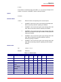
S-Parameters . . . . . . . . . . . . . . . . . . . . . . . . . . . . . . . . . . . . . . . . . . 91
S-Parameter Summary . . . . . . . . . . . . . . . . . . . . . . . . . . . . . . . . . . . . . . . . . . . . .
AT=x - Write to Selected S-Parameter . . . . . . . . . . . . . . . . . . . . . . . . . . . . . . . .
AT? - Read Selected S-Parameter. . . . . . . . . . . . . . . . . . . . . . . . . . . . . .
Sn - Read/Write S-Parameter . . . . . . . . . . . . . . . . . . . . . . . . . . . . . . . .
Factory Defaults . . . . . . . . . . . . . . . . . . . . . . . . . . . . . . . . . . . . . . . . . . . . . . .
S-Parameter Definitions . . . . . . . . . . . . . . . . . . . . . . . . . . . . . . . . . . . . . . . . . .
S0 - Number of Rings to Automatic Answer . . . . . . . . . . . . . . . . . . . . . . .
S1 - Ring Counter . . . . . . . . . . . . . . . . . . . . . . . . . . . . . . . . . . . . . . . .
S2 - Escape Character . . . . . . . . . . . . . . . . . . . . . . . . . . . . . . . . . . . . .
S3 - Line Termination Character. . . . . . . . . . . . . . . . . . . . . . . . . . . . . . .
S4 - Response Formatting Character . . . . . . . . . . . . . . . . . . . . . . . . . . .
S5 - Command Line Editing Character. . . . . . . . . . . . . . . . . . . . . . . . . . .
S6 - Wait Time for Dial Tone Before Blind Dialing, or After "W" Dial Modifier
S7 - Wait Time For Carrier After Dial, For Silence, or For Dial Tone
After "W" Dial Modifier . . . . . . . . . . . . . . . . . . . . . . . . . . . . . . . . . . . . .
S8 - Pause Time For Dial Delay . . . . . . . . . . . . . . . . . . . . . . . . . . . . . . .
S10 - Lost Carrier To Hang Up Delay . . . . . . . . . . . . . . . . . . . . . . . . . . .
S11 - DTMF Tone Duration . . . . . . . . . . . . . . . . . . . . . . . . . . . . . . . . . .
S12 - Escape Prompt Delay (EPD) . . . . . . . . . . . . . . . . . . . . . . . . . . . . .
S18 - Test Timer . . . . . . . . . . . . . . . . . . . . . . . . . . . . . . . . . . . . . . . . .
S28 - Select Pulse Dial/Make/Break Ratio . . . . . . . . . . . . . . . . . . . . . . . .
S29 - Flash Dial Modifier Time . . . . . . . . . . . . . . . . . . . . . . . . . . . . . . . .
S30 - Disconnect Inactivity Timer. . . . . . . . . . . . . . . . . . . . . . . . . . . . . .
S46 - Data Compression Control . . . . . . . . . . . . . . . . . . . . . . . . . . . . . .
S95 - Extended Result Codes Control . . . . . . . . . . . . . . . . . . . . . . . . . . .
S210 - Maximum Symbol Rate. . . . . . . . . . . . . . . . . . . . . . . . . . . . . . . .
.
.
.
.
.
.
.
.
.
.
.
.
.
.
.
.
.
.
.
.
.
.
.
.
.
.
.
.
.
.
.
.
.
.
.
.
.
.
.
.
.
.
.
.
.
.
.
.
.
.
.
.
.
.
.
.
.
.
.
.
.
.
.
.
.
.
.
.
.
.
.
.
.
.
.
.
.
.
91
91
92
92
92
93
93
93
93
93
93
94
94
.
.
.
.
.
.
.
.
.
.
.
.
.
.
.
.
.
.
.
.
.
.
.
.
.
.
.
.
.
.
.
.
.
.
.
.
.
.
.
.
.
.
.
.
.
.
.
.
.
.
.
.
.
.
.
.
.
.
.
.
.
.
.
.
.
.
.
.
.
.
.
.
94
95
95
95
95
96
96
96
96
97
97
97
Fax Class 1 and Fax Class 1.0 Commands . . . . . . . . . . . . . . . . . . . 107
Fax I/O Processing . . . . . . . . . . . . . . . . . . . . . . . . . . . . . . . . . . . . . . . . . . . . . . . . . . . . . 107
v
USRobotics
Command Reference
DTE-to-Modem Transmit Data Stream . . . . . . . . . . . . . . . . . . . . . . . . . . . . . . . . . . . . .
Characters Detected Action Taken . . . . . . . . . . . . . . . . . . . . . . . . . . . . . . . . . .
Modem-to-DTE Receive Data Stream . . . . . . . . . . . . . . . . . . . . . . . . . . . . . . . . . . . . . .
Characters Detected Action Taken . . . . . . . . . . . . . . . . . . . . . . . . . . . . . . . . . .
Fax Mode Selection . . . . . . . . . . . . . . . . . . . . . . . . . . . . . . . . . . . . . . . . . . . . . . . . . .
Fax Origination . . . . . . . . . . . . . . . . . . . . . . . . . . . . . . . . . . . . . . . . . . . . . . . . . . . . .
Fax Answering . . . . . . . . . . . . . . . . . . . . . . . . . . . . . . . . . . . . . . . . . . . . . . . . . . . . .
Fax Control Transmission . . . . . . . . . . . . . . . . . . . . . . . . . . . . . . . . . . . . . . . . . . . . . .
Fax Control Reception . . . . . . . . . . . . . . . . . . . . . . . . . . . . . . . . . . . . . . . . . . . . . . . .
Fax Data Transmission . . . . . . . . . . . . . . . . . . . . . . . . . . . . . . . . . . . . . . . . . . . . . . . .
Fax Data Reception . . . . . . . . . . . . . . . . . . . . . . . . . . . . . . . . . . . . . . . . . . . . . . . . . .
Commands and Parameters . . . . . . . . . . . . . . . . . . . . . . . . . . . . . . . . . . . . . . . . . . . . . . .
Mode Entry Commands . . . . . . . . . . . . . . . . . . . . . . . . . . . . . . . . . . . . . . . . . . . . . . .
+FCLASS=1 - Select Facsimile Class 1 Mode . . . . . . . . . . . . . . . . . . . . . . . . . . .
+FCLASS=1.0 - Select Facsimile Class 1.0 Mode . . . . . . . . . . . . . . . . . . . . . . . .
Mode Commands. . . . . . . . . . . . . . . . . . . . . . . . . . . . . . . . . . . . . . . . . . . . . . . . . . . .
+FAE - Auto Answer Enable . . . . . . . . . . . . . . . . . . . . . . . . . . . . . . . . . . . . . . .
+FTS - Transmit Silence . . . . . . . . . . . . . . . . . . . . . . . . . . . . . . . . . . . . . . . . .
+FRS - Receive Silence . . . . . . . . . . . . . . . . . . . . . . . . . . . . . . . . . . . . . . . . . .
+FTM - Transmit Facsimile . . . . . . . . . . . . . . . . . . . . . . . . . . . . . . . . . . . . . . .
+FRM - Receive Facsimile . . . . . . . . . . . . . . . . . . . . . . . . . . . . . . . . . . . . . . . .
+FTH - Transmit Data with HDLC Framing. . . . . . . . . . . . . . . . . . . . . . . . . . . . .
+FRH - Receive Data with HDLC Framing . . . . . . . . . . . . . . . . . . . . . . . . . . . . .
4.2.3 Service Class 1 Parameters . . . . . . . . . . . . . . . . . . . . . . . . . . . . . . . . . . . . . . . .
+FAR - Adaptive Reception Control. . . . . . . . . . . . . . . . . . . . . . . . . . . . . . . . . .
+FCL - Carrier Loss Timeout . . . . . . . . . . . . . . . . . . . . . . . . . . . . . . . . . . . . . .
+FDD - Double Escape Character Replacement . . . . . . . . . . . . . . . . . . . . . . . . .
+FIT - DTE Inactivity Timeout . . . . . . . . . . . . . . . . . . . . . . . . . . . . . . . . . . . . .
+FPR - Fixed DTE Rate . . . . . . . . . . . . . . . . . . . . . . . . . . . . . . . . . . . . . . . . . .
+FMI - Request Manufacturer Identification. . . . . . . . . . . . . . . . . . . . . . . . . . . .
+FMM - Request Model Identification . . . . . . . . . . . . . . . . . . . . . . . . . . . . . . . .
+FMR - Request Revision Identification . . . . . . . . . . . . . . . . . . . . . . . . . . . . . . .
+FLO - Flow Control . . . . . . . . . . . . . . . . . . . . . . . . . . . . . . . . . . . . . . . . . . . .
Examples . . . . . . . . . . . . . . . . . . . . . . . . . . . . . . . . . . . . . . . . . . . . . . . . . . . . . . . . . . . .
107
107
107
107
107
109
109
109
110
111
112
112
112
112
113
113
113
113
114
114
116
117
118
119
119
119
120
121
122
123
123
124
124
125
Voice Commands . . . . . . . . . . . . . . . . . . . . . . . . . . . . . . . . . . . . . . 127
Voice Commands Overview . . . . . . . . . . . . . . . . . . . . . . . . . . . . . . . . . . . . . . . .
<DLE> Shielded Event Codes Sent to the DTE . . . . . . . . . . . . . . . . . . . . . . . .
<DLE> Shielded Codes Sent to the Modem (DCE) . . . . . . . . . . . . . . . . . . . . . .
Voice Commands . . . . . . . . . . . . . . . . . . . . . . . . . . . . . . . . . . . . . . . . . . . . . . .
Configuration Commands . . . . . . . . . . . . . . . . . . . . . . . . . . . . . . . . . . . . . . .
+FCLASS=8 - Select Voice Mode . . . . . . . . . . . . . . . . . . . . . . . . . . . .
Voice Commands. . . . . . . . . . . . . . . . . . . . . . . . . . . . . . . . . . . . . . . . . . . . .
+VIP - Voice Initialize All Parameters . . . . . . . . . . . . . . . . . . . . . . . . .
+VRX - Start Modem Receive (Record) . . . . . . . . . . . . . . . . . . . . . . . .
+VTR - Start Voice Transmission and Reception (Voice Duplex) . . . . . . .
+VTS - Send Voice Tone(s) . . . . . . . . . . . . . . . . . . . . . . . . . . . . . . . .
+VTX - Start Modem Transmit (Playback) . . . . . . . . . . . . . . . . . . . . . .
+VGR - Voice Gain Receive (Record Gain) . . . . . . . . . . . . . . . . . . . . . .
+VGT - Voice Gain Transmit (Playback Volume) . . . . . . . . . . . . . . . . . .
+VIT - Voice Inactivity Timer (DTE/Modem) . . . . . . . . . . . . . . . . . . . .
+VLS - Analog Source/Destination Selection . . . . . . . . . . . . . . . . . . . .
+VRA - Ringback Goes Away Timer . . . . . . . . . . . . . . . . . . . . . . . . . .
+VRN - Ringback Never Appeared Timer . . . . . . . . . . . . . . . . . . . . . . .
+VSD - Silence Detection (Quiet and Silence) . . . . . . . . . . . . . . . . . . .
+VSM - Compression Method Selection . . . . . . . . . . . . . . . . . . . . . . . .
+VTD - Beep Tone Duration Timer . . . . . . . . . . . . . . . . . . . . . . . . . . .
+VDR - Distinctive Ring . . . . . . . . . . . . . . . . . . . . . . . . . . . . . . . . . .
.
.
.
.
.
.
.
.
.
.
.
.
.
.
.
.
.
.
.
.
.
.
.
.
.
.
.
.
.
.
.
.
.
.
.
.
.
.
.
.
.
.
.
.
.
.
.
.
.
.
.
.
.
.
.
.
.
.
.
.
.
.
.
.
.
.
.
.
.
.
.
.
.
.
.
.
.
.
.
.
.
.
.
.
.
.
.
.
.
.
.
.
.
.
.
.
.
.
.
.
.
.
.
.
.
.
.
.
.
.
.
.
.
.
.
.
.
.
.
.
.
.
.
.
.
.
.
.
.
.
.
.
.
.
.
.
.
.
.
.
.
.
.
.
.
.
.
.
.
.
.
.
.
.
127
128
129
130
130
130
131
131
131
132
132
134
135
135
136
137
138
139
140
141
143
143
vi
USRobotics
Command Reference
+VDT - Control Tone Cadence Reporting . . . . . . . . . . . . . . . . . . .
+VBT - Buffer Threshold Setting . . . . . . . . . . . . . . . . . . . . . . . .
+VPR - Select DTE/Modem Interface Rate (Turn Off Autobaud) . . .
+VSP - Speakerphone ON/OFF . . . . . . . . . . . . . . . . . . . . . . . . . . . . . . .
+VDX - Speakerphone Duplex Mode . . . . . . . . . . . . . . . . . . . . . .
+VGM - Microphone Gain . . . . . . . . . . . . . . . . . . . . . . . . . . . . .
+VGS - Speaker Gain . . . . . . . . . . . . . . . . . . . . . . . . . . . . . . . .
....
....
....
....
....
....
....
.
.
.
.
.
.
.
.
.
.
.
.
.
.
.
.
.
.
.
.
.
.
.
.
.
.
.
.
.
.
.
.
.
.
.
.
.
.
.
.
.
.
.
.
.
.
.
.
.
144
145
146
147
147
148
149
vii
USRobotics
Command Reference
viii
USRobotics
Command Reference
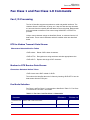
Introduction
Overview
This manual describes the commands and responses for ® host-processed (HSF
or SoftK56) modem families.
The commands and responses described herein are implemented in HSF drivers
V6.02.00 and subsequent.
Additional configuration and implementation information is available in release
notes and/or readme files that accompany product software release. The .INF File
contains exact application unique information and default values.
Command Syntax
The fundamental DTE interface command syntax is described in Chapter 2 Syntax and Procedures.
Command Descriptions
These commands are grouped into the following categories:
Chapter 2 - Syntax and Procedures
Chapter 3 - Data Command Set
Chapter 4 - S-Parameters
Chapter 5 - Fax Class 1 and Fax Class 1.0 Commands
Chapter 6 - Voice Commands
Introduction - 1
USRobotics
Command Reference
Introduction - 2
USRobotics
Command Reference
Syntax and Procedures
The command and response syntax and procedures generally conform to
referenced recommendations and standards. Since these recommendations and
standards describe characteristics universal to a large installed base of modems
to a maximum degree, there may be syntax and procedural differences due to
extensions and behavioral differences in implemented commands, parameters,
and responses beyond that described in these recommendations and standards.
The syntax and procedures described in this section are based on V.250 and
V.253 with additional information included for implemented extensions, behavioral
differences beyond V.250, and legacy commands.
Alphabet
The T.50 International Alphabet 5 (IA5) is used in this document. Only the loworder seven bits of each character are significant to the modem; any eighth or
higher-order bit(s), if present, are ignored for the purpose of identifying commands
and parameters. Lower-case characters are considered identical to their uppercase equivalents when received by the modem from the DTE. Result codes from
the modem are in upper case.
DTE Commands Lines
Words enclosed in <angle brackets> are references to syntactical elements. The
brackets are not used when the words appear in a command line. Words enclosed
in [square brackets] represent optional items which may be omitted from the
command line at the specified point. The square brackets are not used when the
words appear in the command line. Other characters that appear in syntax
descriptions must as included as shown.
Any modem responses are mentioned in terms of their alphabetic format; the
actual response issued will depend on the setting of parameters that affect
response formats, e.g., Q and V commands.
Command Line General Format
A command line is made up of three elements: the prefix, the body, and the
termination character.
The command line prefix consists of the characters "AT" or "at" or, to repeat the
execution of the previous command line, the characters "A/" or "a/".
The body is made up of individual commands described in this document. Space
characters (IA5 2/0) are ignored and may be used freely for formatting purposes,
unless they are embedded in numeric or string constants. The termination
Syntax and Procedures - 3
USRobotics
Command Reference
character may not appear in the body. The modem can accept at least 80
characters in the body.
The termination character may be selected by a user option (parameter S3), the
default being CR.
Command Line Editing
The character defined by parameter S5 (default, BS) is interpreted as a request
from the DTE to the modem to delete the previous character. Any control
characters (IA5 0/0 through 1/15, inclusive) that remain in the command line after
receipt of the termination character are ignored by the modem.
The modem checks characters from the DTE first to see if they match the
termination character (S3), then the editing character (S5), before checking for
other characters. This ensures that these characters will be properly recognized
even if they are set to values that the modem uses for other purposes. If S3 and
S5 are set to the same value, a matching character will be treated as matching S3
(S3 is checked before S5).
Command Line Echo
The modem may echo characters received from the DTE during command state
and online command state back to the DTE, depending on the setting of the E
command. If enabled, characters received from the DTE are echoed in the same
format as received. Invalid characters in the command line or incomplete or
improperly-formed command line prefixes may not be echoed.
Repeating a Command Line
If the prefix "A/" or "a/" is received, the modem immediately executes once again
the body of the preceding command line. No editing is possible, and no
termination character is necessary. A command line may be repeated multiple
times in this manner. Responses to the repeated command line are issued using
format of the original command line. If "A/" is received before any command line
has been executed, the preceding command line is assumed to have been empty
(that results in an OK result code).
Types of DTE Commands
There are two types of commands: action commands and parameter commands.
Commands of either type may be included in command lines, in any order.
Action commands may be "executed" (to invoke a particular function of the
equipment, which generally involves more than the simple storage of a value for
later use), or "tested" (to determine whether or not the equipment implements the
action command, and, if subparameters are associated with the action, the ranges
of subparameter values that are supported).
Syntax and Procedures - 4
USRobotics
Command Reference
Parameters may be "set" (to store a value or values for later use), "read" (to
determine the current value or values stored), or "tested" (to determine whether or
not the equipment implements the parameter, and the ranges of values
supported).
Basic Syntax Commands
Basic Syntax Command Format
The format of Basic Syntax commands, except for the D and S commands, is as
follows:
<command>[<number>]
where <command> is either a single character, or the "&" character followed by a
single character per V.250. In addition, <command> can be the "%" character
followed by a single character, the "*" character followed by a single character, or
the "^" character followed by a single character.
<number> may be a string of one or more characters from "0" through "9"
representing a decimal integer value. Commands that expect a <number> are
noted in the description of the command. If a command expects <number> and it
is missing (<command> is immediately followed in the command line by another
<command> or the termination character), the value "0" is assumed. If a
command does not expect a <number> and a number is present, an ERROR is
generated. All leading "0"s in <number> are ignored by the modem.
Additional commands may follow a command (and associated parameter, if any)
on the same command line without any character required for separation. The
actions of some commands cause the remainder of the command line to be
ignored (e.g., A).
See the D command for details on the format of the information that follows it.
S-Parameters
Commands that begin with the letter "S" are known as "S-parameters". The
number following the "S" indicates the "parameter number" being referenced. If
the number is not recognized as a valid parameter number, an ERROR result
code is issued.
Immediately following this number, either a "?" or "=" character must appear. "?" is
used to read the current value of the indicated S-parameter; "=" is used to set the
S-parameter to a new value.
S<parameter_number>?
S<parameter_number>=[<value>]
Syntax and Procedures - 5
USRobotics
Command Reference
If the "=" is used, the new value to be stored in the S-parameter is specified in
decimal following the "=". If no value is given (i.e., the end of the command line
occurs or the next command follows immediately), the S-parameter specified may
be set to 0, or an ERROR result code issued and the stored value left unchanged.
The ranges of acceptable values are given in the description of each S-parameter.
If the "?" is used, the modem transmits a single line of information text to the DTE.
The text portion of this information text consists of exactly three characters, giving
the value of the S-parameter in decimal, with leading zeroes included.
Extended Syntax Commands
Command Naming Rules
Both actions and parameters have names, which are used in the related
commands. Names always begin with the character "+". Following the "+", from
one to 16 additional characters appear in the command name. These characters
will be selected from the following set:
A through Z
(IA5 4/1 through 5/10)
0 through 9
(IA5 3/0 through 3/9)
!
(IA5 2/1)
%
(IA5 2/5)
-
(IA5 2/13)
.
(IA5 2/14)
/
(IA5 2/15)
:
(IA5 3/10)
_
(IA5 5/15)
The first character following the "+" must be an alphabetic character in the range
of "A" through "Z". This first character generally implies the application in which a
command is used (e.g., F for Fax or V for voice).
The modem considers lower-case characters to be the same as their upper-case
equivalents.
Values
When subparameters are associated with the execution of an action, or when
setting a parameter, the command may include specification of values. This is
indicated by the appearance of <value> in the descriptions below.
Syntax and Procedures - 6
USRobotics
Command Reference
<value>
consists of either a numeric constant or a string constant.
Numeric Constants
Numeric constants are expressed in decimal, hexadecimal, or binary.
Decimal numeric constants consist of a sequence of one or more of the
characters "0" through "9", inclusive.
Hexadecimal numeric constants consist of a sequence of one or more of the
characters "0" through "9", inclusive, and "A" through "F" inclusive. The characters
"A" through "F" represent the equivalent decimal values 10 through 15.
Binary numeric constants consist of a sequence of one or more of the characters
"0" and "1".
In all numeric constants, the most significant digit is specified first. Leading "0"
characters are ignored by the modem. No spaces, hyphens, periods, commas,
parentheses, or other generally-accepted numeric formatting characters are
permitted in numeric constants; note in particular that no "H" suffix is appended to
the end of hexadecimal constants.
String Constants
String constants consist of a sequence of displayable IA5 characters, each in the
range from 2/0 to 7/15, inclusive, except for the characters '"' (IA5 2/2) and "\" (IA5
5/12). String constants are bounded at the beginning and end by the double-quote
character ('"', IA5 2/2).
Any character value may be included in the string by representing it as a
backslash ("\") character followed by two hexadecimal digits. For example, "\0D"
is a string consisting of the single character <CR> (IA5 0/13). If the "\" character
itself is to be represented in a string, it is encoded as "\5C". The double-quote
character, used as the beginning and ending string delimiter, is represented within
a string constant as "\22".
A "null" string constant, or a string constant of zero length, is represented by two
adjacent delimiters ("").
Compound Values
Actions may have more than one subparameter associated with them, and
parameters may have more than one value. These are known as "compound
values", and their treatment is the same in both actions and parameters.
A compound value consists of any combination of numeric and string values (as
defined in the description of the action or parameter). The comma character must
be included as a separator, before the second and all subsequent values in the
compound value. If a value is not specified (i.e., defaults assumed), the required
comma separator must be specified; however, trailing comma characters may be
omitted if all associated values are also omitted.
Syntax and Procedures - 7
USRobotics
Command Reference
Action Commands
Action Execution Command Syntax
There are two general types of action commands: those that have associated
subparameter values that affect only that invocation of the command, and those
that have no subparameters.
If subparameters are associated with a command, the definition of the action
command indicates, for each subparameter, whether the specification of a value
for that subparameter is mandatory or optional. For optional subparameters, the
definition indicates the assumed (default) value for the subparameter if no value is
specified for that subparameter; the assumed value may be either a previous
value (i.e., the value of an omitted subparameter remains the same as the
previous invocation of the same command, or is determined by a separate
parameter or other mechanism), or a fixed value (e.g., the value of an omitted
subparameter is assumed to be zero). Generally, the default value for numeric
subparameters is 0, and the default value for string subparameters is "" (empty
string).
The following syntax is used for actions that have no subparameters:
+<name>
The following syntax is used for actions that have one subparameter:
+<name>[=<value>]
The following syntax is used for actions that have two or more subparameters:
+<name>[=<compound_value>]
For actions that accept subparameters, if all subparameters are defined as being
optional, and the default values for all subparameters are satisfactory, the data
terminal equipment (DTE) may use the first syntax above (i.e., omit the "=" from
the action execution command as well as all of the subparameter value string).
If all other relevant criteria are met (e.g., the modem is in the proper state), the
command is executed with any indicated subparameters. If <name> is not
recognized, the modem issues the ERROR result code and terminates processing
of the command line. An ERROR is also generated if a subparameter is specified
for an action that does not accept subparameters, if too many subparameters are
specified, if a mandatory subparameter is not specified, if a value is specified of
the wrong type, or if a value is specified that is not within the supported range.
Action Test Command Syntax
The DTE may test if an action command is implemented in the modem by using
the syntax:
+<name>=?
If the modem does not recognize the indicated name, it returns an ERROR result
Syntax and Procedures - 8
USRobotics
Command Reference
code and terminates processing of the command line. If the modem does
recognize the action name, it returns an OK result code. If the named action
accepts one or more subparameters, the modem sends an information text
response to the DTE, prior to the OK result code, specifying the values supported
by the modem for each such subparameter, and possibly additional information.
The format of this information text is defined for each action command.
Parameter Commands
Parameter Types
Parameters may be defined as "read-only" or "read-write". "Read-only"
parameters are used to provide status or identifying information to the DTE, but
cannot be set by the DTE; attempting to set their value is an error. In some cases
(specified in the description of the individual parameter), the modem may ignore
attempts to set the value of such parameters rather than respond with an ERROR
result code, if the continued correct operation of the interface between the modem
and DTE will not be affected by such action. Read-only parameters may be read
and tested.
"Read-write" parameters may be set by the DTE, to store a value or values for
later use. Read-write parameters may be set, read, and tested.
Parameters may take either a single value, or multiple (compound) values. Each
value may be either numeric or string; the definition of the parameter will specify
the type of value for each subparameter. Attempting to store a string value in a
numeric parameter, or a numeric value in a string parameter, is an error.
Parameter Set Command Syntax
The definition of the parameter indicates, for each value, whether the specification
of that value is mandatory or optional. For optional values, the definition indicates
the assumed (default) value if none is specified; the assumed value may be either
a previous value (i.e., the value of an omitted subparameter retains its previous
value), or a fixed value (e.g., the value of an omitted subparameter is assumed to
be zero). Generally, the default value for numeric parameters is 0, and the default
value for string parameters is "" (empty string).
The following syntax is used for parameters that accept a single value:
+<name>=[<value>]
The following syntax is used for parameters that accept more than one value:
+<name>=[<compound_value>]
For each implemented parameter, if all mandatory values are specified, and all
values are valid according to the definition of the parameter, the specified values
are stored. If <name> is not recognized, one or more mandatory values are
omitted, or one or more values are of the wrong type or outside the permitted
range, the modem issues the ERROR result code and terminates processing of
the command line. An ERROR is also generated if too many values are specified.
Syntax and Procedures - 9
USRobotics
Command Reference
In case of an error, all previous values of the parameter are unaffected.
Parameter Read Command Syntax
The DTE may determine the current value or values stored in a parameter by
using the following syntax:
+<name>?
The modem responds by sending the current values stored for the parameter to
the DTE in an information text response. The format of this response is described
in the definition of the parameter. Generally, the values are sent in the same form
in which they would be issued by the DTE in a parameter setting command; if
multiple values are supported, they will generally be separated by commas, as in
a parameter setting command.
Parameter Test Command Syntax
The DTE may test if a parameter is implemented in the modem, and determine
the supported values, by using the syntax:
+<name>=?
If the modem does not recognize the indicated name, it returns an ERROR result
code and terminates processing of the command line. If the modem does
recognize the parameter name, it returns an information text response to the DTE,
followed by an OK result code. The information text response indicates the values
supported by the modem for each such subparameter, and possibly additional
information. The format of this information text is defined for each parameter.
Additional Syntax Rules
Concatenating Commands after Extended Syntax Commands
Additional commands may follow an extended-syntax command on the same
command line if a semicolon (";") is inserted after the preceding extended
command as a separator. The semicolon is not necessary when the extended
syntax command is the last command on the command line.
Concatenating Commands after Basic Format Commands
Extended syntax commands may appear on the same command line after a basic
syntax command without a separator, in the same manner as concatenation of
basic syntax commands.
Issuing Commands
All characters in a command line must be issued at the same data rate, and with
Syntax and Procedures - 10
USRobotics
Command Reference
the same parity and format.
The modem will ignore any command line that is not properly terminated. The
modem may consider 30 seconds of mark idle time between any two characters
as an improperly terminated command line. In this case the modem may or may
not generate an ERROR message. The modem will ignore any characters
received from the DTE that are not part of a properly-formatted command line.
If the maximum number of characters that the modem can accept in the body is
exceeded, an ERROR result code is generated after the command line is
terminated.
The DTE will not begin issuing a subsequent command line until at least one-tenth
of a second has elapsed after receipt of the entire result code issued by the
modem in response to the preceding command line.
Executing Commands
Upon receipt of the termination character, the modem commences execution of
the commands in the command line in the order received from the DTE. Should
execution of a command result in an error, or a character be not recognized as a
valid command, execution is terminated, the remainder of the command line is
ignored, and the ERROR result code is issued. Otherwise, if all commands
execute correctly, only the result code associated with the last command is
issued; result codes for preceding commands are suppressed. If no commands
appear in the command line, the OK result code is issued.
Aborting Commands
Some action commands that require time to execute may be aborted while in
progress; these are explicitly noted in the description of the command. Aborting of
commands is accomplished by the transmission from the DTE to the modem of
any character. A single character is sufficient to abort the command in progress;
however, characters transmitted during the first 125 milliseconds after
transmission of the termination character are ignored (to allow for the DTE to
append additional control characters such as line feed after the command line
termination character). To ensure that the aborting character is recognized by the
modem, it should be sent at the same rate as the preceding command line; the
modem may ignore characters sent at other rates. When such an aborting event
is recognized by the modem, the modem terminates the command in progress
and returns an appropriate result code to the DTE, as specified for the particular
command.
Handling of Invalid Numbers and S-Parameter Values
The modem reacts to undefined numbers and S-parameter values in one of three
ways:
•
Issue the ERROR result code, and leave the previous value of the
Syntax and Procedures - 11
USRobotics
Command Reference
parameter unchanged;
• Issue the OK result code, and leave the previous value of the parameter unchanged; or,
• Issue the OK result code, and set the parameter value to the valid
value nearest to that specified in the command line.
The description of each command specifies which of these three techniques is
used to handle invalid parameter values for that command or parameter.
Modem Responses
While in command state and online command state, the modem will issue
responses using the same rate, word length, and parity as the most recently
received DTE command line. In the event that no DTE command has yet been
received, rate, word length, and parity used will depend on the capabilities of the
modem.
When the modem transitions from the command state or online command state to
the online data state, the result code CONNECT should be issued at the bit rate
and parity used during the command state. When the modem transitions from the
online data state to the command state or online command state, the result codes
should be issued at the bit rate used during the online data state. Thereafter, any
unsolicited result codes should use the bit rate and parity of the last command line
issued by the DTE to the modem.
The characters of a response will be contiguous, with no more than 100
milliseconds of mark idle issued between characters in addition to stop elements.
Responses
There are two types of responses that may be issued by the modem: information
text and result codes.
Information Text.
Information text responses consist of three parts: a header, information text, and a
trailer:
The characters transmitted for the header are determined by the V command.
The trailer consists of two characters, being the character having the ordinal value
of parameter S3 followed by the character having the ordinal value of parameter
S4.
Information text usually consists of a single line; information text returned in
response to some commands may contain multiple lines, and the text may
therefore include CR, LF, and other formatting characters to improve readability.
Syntax and Procedures - 12
USRobotics
Command Reference
Result Code Parts
Result codes consist of three parts: a header, the result text, and a trailer.
The characters transmitted for the header and trailer are determined by the V
command setting.
The result text may be transmitted as a number or as a string, also depending on
a the V command setting.
Result Code Types
There are three types of result codes: final, intermediate, and unsolicited. Result
codes are described in Section 3.4.
A final result code indicates the completion of a full modem action and an ability to
accept new commands from the DTE.
An intermediate result code is a report of the progress of an modem action. The
CONNECT result code is an intermediate result code. In the case of a dialing or
answering command, the modem switches from command state to online data
state, and issues a CONNECT result code. This is an intermediate result code for
the modem because it cannot accept commands from the DTE while in online
data state. When the modem switches back to the command state it then issues a
final result code (such as OK or NO CARRIER).
Unsolicited result codes (such as RING) indicate the occurrence of an event not
directly associated with the issuance of a command from the DTE.
Extended Syntax Result Codes
Extended syntax result codes may be issued in response to either basic or
extended commands, or both. The appropriate responses are specified in the
definitions of the commands, the responses, or both.
The general format of extended syntax result codes is the same as result codes
defined in TIA602 with regard to headers and trailers. The characters specified in
S-parameters S3 and S4 are used in headers and trailers of extended syntax
result codes as they are in basic format result codes. The setting of the V
command affects the headers and trailers associated with extended syntax result
codes in the same manner as basic format result codes; however, unlike basic
format result codes, extended syntax result codes have no numeric equivalent,
and are always issued in alphabetic form.
Extended syntax result codes are subject to suppression by the Q1 command, as
with basic format result codes. The issuance of extended syntax result codes are
not be affected by the setting of the X command.
Extended syntax result codes may be either final, intermediate, or unsolicited; the
type being indicated in the definition of the result code.
Extended syntax result codes are prefixed by the "+" character to avoid
Syntax and Procedures - 13
USRobotics
Command Reference
duplication of basic format result codes specified in TIA-602. Following the "+"
character, the name of the result code appears; result code names follow the
same rules as command names.
Extended syntax result codes may include the reporting of values. The definition
of the result code specifies whether or not values are appended to the result code,
and, if so, how many, their types, and their assumed default values if omitted.
Data/voice Modes. When no values are to be reported, the result code appears in
the simplest form:
+<name>
If a single value is to be reported, the form of the result code is:
+<name>: <value>
A single space character separates the colon character from the <value>; no
space appears between the result code name and the colon. If multiple values are
to be reported with the result code, the form is:
+<name>: <compound_value>
Fax Modes
If a single value is to be reported, the form of the result code is:
<value> or (<value>)
+<name>: <compound_value>Information Text Formats for Test Commands
In general, the format of information text returned by extended syntax commands
is described in the definition of the command.
The modem may insert intermediate <CR> characters in very long information
text responses in order to avoid overrunning DTE receive buffers. If intermediate
<CR> characters are included, the modem does not include the character
sequences "0 <CR>"or "OK<CR>", so that DTE can avoid false detection of the
end of these information text responses.
Range of Values
When the action accepts a single numeric subparameter, or the parameter
accepts only one numeric value, the set of supported values may be presented in
the information text as an ordered list of values. The list is preceded by a left
parenthesis (() , and is followed by a right parenthesis ()). If only a single value is
supported, it appears between the parentheses. If more than one value is
supported, then the values may be listed individually, separated by comma
characters, or, when a continuous range of values is supported, by the first value
in the range, followed by a hyphen character (-), followed by the last value in the
range. The specification of single values and ranges of values may be intermixed
within a single information text. In all cases, the supported values are indicated in
ascending order.
Syntax and Procedures - 14
USRobotics
Command Reference
For example, the following are some examples of value range indications:
(0)
Only the value 0 is supported.
(1,2,3)
The values 1, 2, and 3 are supported.
(1-3)
The values 1 through 3 are supported.
(0,4,5,6,9,11,12) The several listed values are supported.
(0,4-6,9,11-12) An alternative expression of the above list.
Compound Range of Values
When the action accepts more than one subparameter, or the parameter accepts
more than one value, the set of supported values is presented as a list of the
parenthetically-enclosed value range strings described above, separated by
commas. For example, the information text in response to testing an action that
accepts three subparameters, and supports various ranges for each of them,
could appear as follows:
(0),(1-3),(0,4-6,9,11-12)
This indicates that the first subparameter accepts only the value 0, the second
accepts any value from 1 through 3 inclusive, and the third subparameter accepts
any of the values 0, 4, 5, 6, 9, 11, or 12.
Syntax and Procedures - 15
USRobotics
Command Reference
Syntax and Procedures - 16
USRobotics
Command Reference
Data Command Set
Command Guidelines
The commands used to control and report modem operation in data modem mode
are defined in this section.
The Data Modem Mode commands and responses described in this section are
applicable when command +FCLASS=0. (See +FCLASS for the definition of the
FCLASS command.)
The default values are typical of a fully configured modem supporting all data
rates and options. The actual default value is dependent upon modem software as
defined by the .INF File.
Commands are accepted by the modem once the previous command has been
fully executed, which is normally indicated by the return of an appropriate result
code. Execution of commands D and A, either as a result of a direct command or
a re-execute command, will be aborted if another character is entered before
completion of the handshake.
Escape Code Sequence
When the modem has established a connection and has entered on-line data
mode, it is possible to break into the data transmission in order to issue further
commands to the modem in an on-line command mode. This is achieved by the
DTE sending to the modem a sequence of three ASCII characters specified by
register S2. The default character is '+'. The maximum time allowed between
receipt of the last character of the three escape character sequence from the DTE
and sending of the OK result code to the DTE is controlled by the S12 register.
Data Commands
The modem will respond to the commands detailed below. Parameters applicable
to each command are listed with the command description. The defaults shown
correspond to default values provided in the .INF File.
Generic Modem Control
Z - Reset to Default Configuration
This command instructs the modem to reset to default values as altered by nonvolatile parameter storage. If the modem is connected to the line, it will be
disconnected from the line, terminating any call in progress.
Data Command Set - 17
USRobotics
Command Reference
All of the functions of the command are completed before the modem issues the
result code. The DTE should not include additional commands on the same
command line after the Z command because such commands are ignored.
Syntax
Z
Result Code
OK
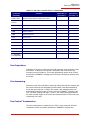
+FCLASS - Select Active Service Class
This command selects the active service class (mode).
Syntax
+FCLASS=<mode>
Defined Values
<mode>
Decimal number which corresponds to the selected service class.
0
Select Data Mode (Default.)
1
Select Facsimile Class 1 Mode
1.0
Select Facsimile Class 1.0 Mode
8
Select Voice Mode
Result Codes
OK
For <mode> = 0, 1, 1.0, and 8, as supported by the .INF File.
ERROR
Otherwise.
Reporting Current or Selected Values
Command:
+FCLASS?
Response:
+FCLASS: <mode>
Example:
+FCLASS: 0 For the default setting.
Reporting Supported Range of Parameter Values
Command:
+FCLASS=?
Response:
+FCLASS: (<mode> range)
Example:
+FCLASS: (0, 1,1.0,8)
Data Command Set - 18
USRobotics
Command Reference
+VCID - Caller ID (CID)
This command controls the reporting and presentation of data associated with the
Caller ID services in the U.S. and Canada in the Incoming Call Line ID (ICLID)
data format.
Syntax
+VCID=<pmode>
Defined Values
<pmode>
Decimal number corresponding to the selected option.
0
Disable Caller ID reporting. (Default).
1
Enables Caller ID with formatted presentation to the DTE. The
modem will present the data items in a <Tag><Value> pair format.
The expected pairs are data, time, caller code (telephone
number), and name.
2
Enables Caller ID with unformatted presentation to the DTE.
Reporting Current or Selected Values
Command:
+VCID?
Response:
+VCID: <pmode>
Example:
+VCID: 0 For the default setting.
Reporting Supported Range of Parameter Values
Command:
+VCID=?
Response:
+VCID: (<pmode> range)
Example:
+VCID: (0,1,2)
+VRID - Report Retieved Caller ID (CID)
This command reports the data associated with the Caller ID services in the
Incoming Call Line ID (ICLID) data format for the last received call.
Syntax
+VRID=<pmode>
Defined Values
<pmode>
Decimal number corresponding to the selected option.
Data Command Set - 19
USRobotics
Command Reference
0
Reports Caller ID with formatted presentation to the DTE. The
modem presents the data items in a <Tag><Value> pair format.
The expected pairs are date, time, name, and caller code
(telephone number),
1
Reports Caller ID with unformatted presentation to the DTE.
Reporting Supported Range of Parameter Values
Command:
+VRID=?
Response:
+VRID: (<pmode> range)
Example:
+VRID: (0,1)
\N - Operating Mode
This command controls the preferred error correcting mode to be negotiated in a
subsequent data connection.
Syntax
\N<mode>
Defined Values
<mode>
Decimal number which corresponds to the selected mode.
0
Selects normal speed buffered mode (disables error-correction
mode) and forces &Q6 (selects asynchronous operation in
normal mode.)
1
Same as \N0.
2
Selects reliable (error-correction) mode and forces &Q5 (the
modem will try to negotiate an error corrected link). The modem
will first attempt a LAPM connection and then an MNP
connection. Failure to make a reliable connection results in the
modem hanging up.
3
Selects auto reliable mode and forces &Q5 (the modem will try to
negotiate an error corrected link). This operates the same as \N2
except failure to make a reliable connection results in the modem
falling back to the speed buffered normal mode.
4
Selects LAPM error-correction mode and forces &Q5 (the modem
will try to negotiate an error corrected link). Failure to make an
LAPM error-correction connection results in the modem hanging
up.
Data Command Set - 20
USRobotics
Command Reference
5
Selects MNP error-correction mode and forces &Q5 (the modem
will try to negotiate an error corrected link). Failure to make an
MNP error-correction connection results in the modem hanging
up.
Result Codes
OK
<mode> = 0 to 5.
ERROR
Otherwise.
&F - Set to Factory-Defined Configuration
This command instructs the modem to set all parameters to factory default values
defined in the product Configuration Table
The modem loads the factory default configuration (profile). The factory defaults
are identified for each command and in the S-Parameter descriptions. A
configuration (profile) consists of a subset of S-Parameters.
Syntax
&F
Result Code
OK
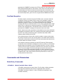
&T - Local Analog Loopback Test
The modem will perform the local analog loopback test if &T1 is selected. The test
can be run only when in an asynchronous operation in non-error-correction mode
(normal). To terminate the test in progress, the escape sequence must be entered
first. If S18 is non-zero, the test will terminate automatically after the time
specified by S18 and the OK result code will be reported.
Syntax
&T[<value>]
Defined Values
<value>
Decimal number corresponding to the selected value.
0
Terminates test in progress.
1
Initiates local analog loopback, V.54 Loop 3. If a connection exists
when this command is issued, the modem hangs up. The
CONNECT XXXX message is displayed upon the start of the test.
I - Request Identification Information
This command causes the modem to report one or more lines of product
Data Command Set - 21
USRobotics
Command Reference
information text, as selected by the <value> subparameter, followed by a final
result code.
Syntax
I[<value>]
Defined Values
<value>
Decimal number corresponding to the selected information.
0
Reports product code, e.g.: ATI0 56000 OK
1
Reports the least significant byte of the stored checksum in
decimal. Reports 255 if the prestored checksum value is FFh,
e.g., ATI1 255 OK
2
Reports OK, e.g.: ATI2 OK
3
Reports identification codes, e.g.: ATI3 SoftK56V_B2.1_V7.04.05
OK
4
Reports product description from the .INF file (the response is
customizable by customizing the INF file), e.g.: ATI4 SoftK56
Data Fax OK
5
Reports Country Code parameter (in decimal), e.g.: ATI5 181 OK
6
Reports modem data pump model and internal code revision,
e.g.: ATI6 SoftK56 CModem Version 12 Rksample Version 342
OK
7
Reports 255 and OK, e.g.: ATI7 255 OK
8
Reports build date and time, e.g.: ATI8 Jan 7 2004 # 15:45:08 OK
9
Reports country, e.g.: ATI9 USA OK
Result Codes
OK
<value> = 0-9.
ERROR
Otherwise.
+GMI - Request Manufacturer Identification
This command causes the modem to report the modem product manufacturer as
provided by the .INF File.
Syntax
+GMI
Data Command Set - 22
USRobotics
Command Reference
Typical Response
+GMI:
OK
+GMM - Request Model Identification
This command causes the modem to report the modem product model as
provided by the .INF File.
Syntax
+GMM
Typical Response
+GMM: HSF 56K Data, Fax, Speakerphone, PCI Modem
OK
+GMR - Request Revision Identification
This command causes the modem to report the modem version, revision level, or
date as provided by the .INF File.
Syntax
+GMR
Typical Response
+GMR: 1.0
OK
+GSN - Request Product Serial Number Identification
This command causes the modem to report the modem product model serial
number as provided by the .INF File.
Syntax
+GSN
Typical Response
+GSN:
OK
Data Command Set - 23
USRobotics
Command Reference
+GOI - Request Global Object Identification
This command causes the modem to transmit one or more lines of information
text identifying the device, based on the ISO system for registering unique object
identifiers. Typically, the text consists of a single line containing numeric strings
delimited by period characters. The general format of object identifiers is defined
in Section 28 of ITU-T Recommendation X.208; the encoding rules are defined in
ITU-T Recommendation X.209. The response is provided by the .INF file.
Syntax
+GOI
Typical Response
+GOI:
OK
+GCAP - Request Complete Capabilities List
This extended-format command causes the modem to transmit one or more lines
of information text listing additional capabilities command +<name>s , which is
intended to permit the user to identify the overall capabilities of the modem. In
particular, if the modem implements a particular modem control standard that
uses Extended Syntax Commands, and if that modem control standard includes
command(s) that indicate general capabilities, the +<names>(s) of those
commands will be reported to the modem in response to a +GCAP command.
Syntax
+GCAP
Example Responses
+GCAP: +FCLASS, +MS, +ES, +DS, for a data modem that supports all
capabilities listed Where:
+FCLASS T.class1, +F (Class 1 Facsimile modem Control)
+MS +M commands (Modulation Control: +MS and +MR commands)
+ES +E commands (Error Control: +ES, +EB, +ER, +EFCS, +ETBM)
+DS +D commands (Data Compression: +DS and +DR)
+GCI - Country of Installation
This extended syntax command indicates and selects the country of installation
for the modem. This parameter selects the settings for any operational
parameters that need to be adjusted for national regulations or telephone
networks.
Data Command Set - 24
USRobotics
Command Reference
Syntax
+GCI=<country_code>
Defined Values
<country_code>8-bit country code from Annex A of T.35. The value is the
hexadecimal equivalent of the T.35 code, with bit 8 treated as the
most significant bit and bit 1 treated as the least significant bit.
Default
If the modem is specified for use in only one country, that country code is the
default. Otherwise, the default is the expected country of sale or first installation.
The modem may use hardware means to select the country of installation, in
which case the modem uses that to determine the default value.
Reporting Current or Selected Values
Command:
+GCI?
Response:
+GCI: <current country_code>
Example:
+GCI: 3D Indicates that the modem is set for France.
Reporting Supported Range of Parameter Values
Command:
+GCI=?
Response:
+GCI: (<country_code>[,<country_code>[,<country_code].......]]
Example:
+GCI: (20,73,B5)The modem can be set for Canada, Mexico or
the United States.
DTE-Modem interface Commands
The parameters defined in this section control the operation of the interface
between the DTE and modem.
E - Command Echo
The modem enables or disables the echo of characters to the DTE according to
the parameter supplied.
Syntax
E[value>]
Data Command Set - 25
USRobotics
Command Reference
Defined Values
<value>
Decimal number corresponding to the selected option.
0
Disables command echo.
1
Enables command echo. (Default.)
Result Codes
OK
<value> = 0 or 1.
ERROR
Otherwise.
Q - Quiet Results Codes Control
The command enables or disables the sending of result codes to the DTE
according to the parameter supplied. The parameter value, if valid, is written to
S14 bit 2.
Syntax
O[value>]
Defined Values
<value>
Decimal number corresponding to the selected option.
0
Enables result codes to the DTE. (Default.)
1
Disables result codes to the DTE.
Result Codes
OK
<value> = 0 or 1.
ERROR
Otherwise.
V - Result Code Form
This command selects the sending of short-form or long-form result codes to the
DTE.
Syntax
V[value>]
Defined Values
<value>
Decimal number corresponding to the selected option.
0
Enables short-form (terse) result codes. Line feed is not issued
before a short-form result code.
Data Command Set - 26
USRobotics
Command Reference
1
Enables long-form (verbose) result codes. (Default.)
Result Codes
OK
<value> = 0 or 1.
ERROR
Otherwise.
W - Connect Message Control
This command, in conjunction with S95 bits 0, 2, 3, and 5 (bits 2, 3, and 5 can be
written directly by the host or by the +MR, +ER, and +DR commands,
respectively), control the format of CONNECT messages (see Table 3-15). The
actual result code messages reported reflect the W command setting and the S95
bit settings. (Also see +MR, +ER, and +DR commands.)
Syntax
W[value>]
Defined Values
<value>
Decimal number corresponding to the selected option.
0
Upon connection, the modem reports only the DTE speed (e.g.,
CONNECT 19200). Subsequent responses are disabled.
(Default.)
1
Upon connection, the modem reports the line speed, the error
correction protocol, and the DTE speed, respectively.
Subsequent responses are disabled.
2
Upon connection, the modem reports the DCE speed (e.g.,
CONNECT 14400). Subsequent responses are disabled.
3
Upon connection, the modem reports DCE speed and the error
correction protocol.
Result Codes
OK
<value> = 0-3.
ERROR
Otherwise.
X - Extended Result Codes
This command selects the subset of the result code messages used by the
modem to inform the DTE of the results of commands.
Blind dialing is enabled or disabled by country parameters. If the user wishes to
enforce dial tone detection, a "W" can be placed in the dial string (see D
command). The information below is based upon the default implementation of
the X results table. Table 3-1 indicates the messages which are enabled for each
Data Command Set - 27
USRobotics
Command Reference
X value.
If the modem is in facsimile mode (+FCLASS=1, or 1.0), the only message sent to
indicate a connection is CONNECT without a speed indication.
Syntax
X<value>
Defined Values
<value>
Decimal number corresponding to the selected option.
0
CONNECT result code is given upon entering online data state.
Dial tone and busy detection reporting are disabled.
1
CONNECT <text> result code is given upon entering online data
state. Dial tone and busy detection reporting are disabled.
2
CONNECT <text> result code is given upon entering online data
state. Dial tone detection reporting is enabled, and busy detection
reporting is disabled.
3
CONNECT <text> result code is given upon entering online data
state. Dial tone detection reporting is disabled, and busy
detection reporting is enabled.
4
CONNECT <text> result code is given upon entering online data
state. Dial tone and busy detection reporting are both enabled.
(Default.)
Result Codes
OK
<value> = 0 to 4.
ERROR
Otherwise.
Table 3-1: Result Codes
Short Form
Long Form
n Value in ATXn Command
Notes
0
1
2
3
4
+F4
+FCERROR
x
x
x
x
x
0
OK
x
x
x
x
x
1
CONNECT
x
x
x
x
x
2
RING
x
x
x
x
x
3
NO CARRIER
x
x
x
x
x
4
ERROR
x
x
x
x
x
5
CONNECT 1200
1
x
x
x
x
6
NO DIALTONE
3
3
x
x
x
Data Command Set - 28
USRobotics
Command Reference
Table 3-1: Result Codes
Short Form
Long Form
n Value in ATXn Command
Notes
7
BUSY
3
3
3
x
x
8
NO ANSWER
x
x
x
x
x
9
CONNECT 600
1
x
x
x
x
10
CONNECT 2400
1
x
x
x
x
11
CONNECT 4800
1
x
x
x
x
12
CONNECT 9600
1
x
x
x
x
13
CONNECT 7200
1
x
x
x
x
14
CONNECT 12000
1
x
x
x
x
15
CONNECT 14400
1
x
x
x
x
16
CONNECT 19200
1
x
x
x
x
17
CONNECT 38400
1
x
x
x
x
18
CONNECT 57600
1
x
x
x
x
19
CONNECT 115200
1
x
x
x
x
20
CONNECT 230400
x
x
x
x
x
22
CONNECT 75TX/
1200RX
1
x
x
x
x
23
CONNECT 1200TX/
75RX
1
x
x
x
x
24
DELAYED
4
4
4
4
x
32
BLACKLISTED
4
4
4
4
x
33
FAX
x
x
x
x
x
35
DATA
x
x
x
x
x
40
+MRR: 300
x
x
x
x
x
44
+MRR: 1200/75
x
x
x
x
x
45
+MRR: 75/1200
x
x
x
x
x
46
+MRR: 1200
x
x
x
x
x
47
+MRR: 2400
x
x
x
x
x
48
+MRR: 4800
x
x
x
x
x
49
+MRR: 7200
x
x
x
x
x
50
+MRR: 9600
x
x
x
x
x
51
+MRR: 12000
x
x
x
x
x
52
+MRR: 14400
x
x
x
x
x
53
+MRR: 16800
x
x
x
x
x
Data Command Set - 29
USRobotics
Command Reference
Table 3-1: Result Codes
Short Form
Long Form
n Value in ATXn Command
Notes
54
+MRR: 19200
x
x
x
x
x
55
+MRR: 21600
x
x
x
x
x
56
+MRR: 24000
x
x
x
x
x
57
+MRR: 26400
x
x
x
x
x
58
+MRR: 28800
x
x
x
x
x
59
CONNECT 16800
1
x
x
x
x
61
CONNECT 21600
1
x
x
x
x
62
CONNECT 24000
1
x
x
x
x
63
CONNECT 26400
1
x
x
x
x
64
CONNECT 28800
1
x
x
x
x
66
+DR: ALT
x
x
x
x
x
67
+DR: V42B
x
x
x
x
x
69
+DR: NONE
x
x
x
x
x
70
+ER: NONE
x
x
x
x
x
77
+ER: LAPM
x
x
x
x
x
78
+MRR: 31200
x
x
x
x
x
79
+MRR: 33600
x
x
x
x
x
80
+ER: ALT
x
x
x
x
x
83
LINE IN USE
x
x
x
x
x
84
CONNECT 33600
1
x
x
x
x
91
CONNECT 31200
1
x
x
x
x
134
+MCR: B103
x
x
x
x
x
135
+MCR: B212
x
x
x
x
x
136
+MCR: V21
x
x
x
x
x
137
+MCR: V22
x
x
x
x
x
138
+MCR: V22B
x
x
x
x
x
139
+MCR: V23
x
x
x
x
x
140
+MCR: V32
x
x
x
x
x
141
+MCR: V32B
x
x
x
x
x
142
+MCR: V34
x
x
x
x
x
145
+MCR: V90
x
x
x
x
x
150
+MRR: 32000
x
x
x
x
x
Data Command Set - 30
USRobotics
Command Reference
Table 3-1: Result Codes
Short Form
Long Form
n Value in ATXn Command
Notes
151
+MRR: 34000
x
x
x
x
x
152
+MRR: 36000
x
x
x
x
x
153
+MRR: 38000
x
x
x
x
x
154
+MRR: 40000
x
x
x
x
x
155
+MRR: 42000
x
x
x
x
x
156
+MRR: 44000
x
x
x
x
x
157
+MRR: 46000
x
x
x
x
x
158
+MRR: 48000
x
x
x
x
x
159
+MRR: 50000
x
x
x
x
x
160
+MRR: 52000
x
x
x
x
x
161
+MRR: 54000
x
x
x
x
x
162
+MRR: 56000
x
x
x
x
x
165
CONNECT 32000
x
x
x
x
x
166
CONNECT 34000
x
x
x
x
x
167
CONNECT 36000
x
x
x
x
x
168
CONNECT 38000
x
x
x
x
x
169
CONNECT 40000
x
x
x
x
x
170
CONNECT 42000
x
x
x
x
x
171
CONNECT 44000
x
x
x
x
x
172
CONNECT 46000
x
x
x
x
x
173
CONNECT 48000
x
x
x
x
x
174
CONNECT 50000
x
x
x
x
x
175
CONNECT 52000
x
x
x
x
x
176
CONNECT 54000
x
x
x
x
x
177
CONNECT 56000
x
x
x
x
x
178
CONNECT 230400
x
x
x
x
x
180
CONNECT 28000
x
x
x
x
x
181
CONNECT 29333
x
x
x
x
x
182
CONNECT 30667
x
x
x
x
x
183
CONNECT 33333
x
x
x
x
x
184
CONNECT 34667
x
x
x
x
x
185
CONNECT 37333
x
x
x
x
x
Data Command Set - 31
USRobotics
Command Reference
Table 3-1: Result Codes
Short Form
Long Form
n Value in ATXn Command
Notes
186
CONNECT 38667
x
x
x
x
x
187
CONNECT 41333
x
x
x
x
x
188
CONNECT 42667
x
x
x
x
x
189
CONNECT 45333
x
x
x
x
x
190
CONNECT 46667
x
x
x
x
x
191
CONNECT 49333
x
x
x
x
x
192
CONNECT 50667
x
x
x
x
x
193
CONNECT 53333
x
x
x
x
x
194
CONNECT 54667
x
x
x
x
x
195
+MRR: 28000
x
x
x
x
x
196
+MRR: 29333
x
x
x
x
x
197
+MRR: 30667
x
x
x
x
x
198
+MRR: 33333
x
x
x
x
x
199
+MRR: 34667
x
x
x
x
x
200
+MRR: 37333
x
x
x
x
x
201
+MRR: 38667
x
x
x
x
x
202
+MRR: 41333
x
x
x
x
x
203
+MRR: 42667
x
x
x
x
x
204
+MRR: 45333
x
x
x
x
x
205
+MRR: 46667
x
x
x
x
x
206
+MRR: 49333
x
x
x
x
x
207
+MRR: 50667
x
x
x
x
x
208
+MRR: 53333
x
x
x
x
x
209
+MRR: 54667
x
x
x
x
x
Note: An 'x' in a column indicates that the message (either the long form if verbose, or the value only for short
form) will be generated when that particular value of 'n' (shown at the top of the column) has been selected
by the use of ATXn. If the column is blank, then no message will be generated for that x option. A numeral
indicates which less explicit message (verbose or short form) will be output for that X option.
&C - RLSD Behavior
This parameter determines how the state of the Received Line Signal Detector
(RLSD) output relates to the detection of received line signal from the distant end.
Changing the parameter will take effect immediately in both the command and
online command states.
Data Command Set - 32
USRobotics
Command Reference
In &C1 mode of operation, RLSD is not turned off until all data previously received
from the remote modem is delivered to the local DTE. However, such buffered
data will be discarded and RLSD will be turned off if the DTE turns off DTR (if &D1
or &D2 is set).
Syntax
&C[<value>]
Defined Values
<value> Decimal number corresponding to the selected option. 0 RLSD is always
ON. 1 RLSD follows the state of the carrier. (Default.)
Result Code
OK
<value> = 0 or 1
ERROR
Otherwise.
&D - DTR Behavior
This parameter determines how the modem responds when the Data Terminal
Ready (DTR) input is changed from the ON to the OFF condition during online
data state.
Syntax
&D[<value>]
Defined Values
<value>
Decimal number corresponding to the selected option.
0
Modem ignores DTR.
1
Upon an on-to-off transition of DTR, the modem enters online
command state and issues an OK result code; the call remains
connected.
2
Upon an on-to-off transition of DTR, the modem instructs the
underlying modem to perform an orderly cleardown of the call.
The disposition of any data in the modem pending transmission
to the remote modem is controlled by the +ETBM parameter;
otherwise, this data is sent before the call is cleared, unless the
remote modem clears the call first (in which case pending data is
discarded). The modem disconnects from the line. Automatic
answer is disabled while DTR remains off.
Result Code
OK
<value> = 0 or 2
ERROR
Otherwise.
Data Command Set - 33
USRobotics
Command Reference
&K - Flow Control
This command defines the DTE/DCE (terminal/modem) flow control mechanism.
Syntax
&K[<value>]
Defined Values
<value>
Decimal number corresponding to the selected option.
0
Disables flow control.
3
Enables RTS/CTS flow control. (Default for data modem modes.)
4
Enables XON/XOFF flow control.
5
Included for compatibility only and has no effect other than
returning an OK result code.
6
Included for compatibility only and has no effect other than
returning an OK result code.
Result Codes
OK
<value> = 0, 3, 4, 5, or 6.
ERROR
Otherwise.
&M - Asynchronous/Synchronous Mode Selection
This command is included for compatibility only and has no effect other than
returning a result code. The only valid values are 0-3.
Syntax
&M[<mode>]
Defined Values
<mode >
Decimal number corresponding to the selected value: 0-3.
OK
<mode> = 0 to 3.
ERROR
Otherwise.
Result Codes
&Q - Sync/Async Mode
This command determines the DTR operating mode. (Also, see \N.)
Data Command Set - 34
USRobotics
Command Reference
Note: When the &Q0 is issued to select the mode, the subsequent connect message will report the DCE speed
regardless of the W command and S95 settings.
Syntax
&Q[<mode>]
Defined Values
<mode >
Decimal number corresponding to the selected mode:
0
Selects asynchronous operation in normal mode (speed
buffering)
1
Selects asynchronous operation in normal mode (speed
buffering)
2
Selects asynchronous operation in normal mode (speed
buffering)
3
Selects asynchronous operation in normal mode (speed
buffering)
5
Selects asynchronous operation in error correction mode
6
Selects asynchronous operation in normal mode (speed
buffering)
Result Codes
OK
<mode > = 0-3, 5, 6.
ERROR
Otherwise.
+IPR - Fixed DTE Rate
This numeric extended-format parameter specifies the data rate at which the
modem will accept commands during online operation. It may be used to select
operation at rates at which the modem is not capable of automatically detecting
the data rate being used by the DTE. Specifying a value of 0 disables the function
and allows operation only at rates automatically detectable by the modem. The
specified rate takes effect following the issuance of any result code(s) associated
with the current command line.
The <rate> specified does not apply in OnLine Data State if Normal Mode (Direct
Mode) of operation is selected.
Syntax
+IPR=<rate>
Data Command Set - 35
USRobotics
Command Reference
Defined Values
<rate>
Specifies the DTE-modem interface operation rate in bits/s. The
available rates are: 0, 2400, 4800, 9600, 19200, 38400, 57600, or
115200.
If unspecified or set to 0, automatic detection is selected and the character format
is also forced to autodetect, +ICF=0.
If the rate specified is not supported by the modem, an ERROR result code will be
returned.
Reporting Current or Selected Values
Command:
+IPR?
Response:
+IPR: <rate>
Example 1:
+IPR: 0 for automatic rate detection.
Example 2:
+IPR: 57600 for 57600 bps.
Reporting Supported Range of Parameter Values
Command:
+IPR=?
Response:
+IPR (<rate> range)
Example:
+IPR: (0, 2400,4800,9600,19200,38400,57600,115200)
+IFC - DTE-Modem Local Flow Control
This extended-format compound parameter controls the operation of local flow
control between the DTE and the modem during the data state when V.42 error
control is used, or when fallback to non-error control mode is specified to include
buffering and flow control. It accepts two numeric subparameters.
Syntax
+IFC=[<modem_by_DTE>[,<DTE_by_modem>]]
Defined Values
<modem_by_DTE>
Specifies the method to be used by the DTE to control the flow of
received data from the modem. 0 None.
1
XON/XOFF on transmitted data (XON/XOFF on transmit data);
do not pass XON/XOFF characters to the remote modem.
2
Circuit 133 (Ready for Receiving). (Default.) <DTE_by_modem>
Specifies the method to be used by the modem to control the flow
of transmitted data from the DTE. 0 None. 1 XON/XOFF on
received data. 2 CTS/RTS. (Default.)
Data Command Set - 36
USRobotics
Command Reference
Reporting Current or Selected Values
Command:
+IFC?
Response:
+IFC: <modem_by_DTE>,<DTE_by_modem> Example: +IFC:
2,2 for the defaults.
Reporting Supported Range of Parameter Values
Command:
+IFC=?
Response:
+IFC: (<modem_by_DTE> range),(<DTE_by_modem> range)
Example:
+IFC: (0-2),(0-2)
+ILRR - DTE-Modem Local Rate Reporting
This extended-format numeric parameter controls whether or not the extendedformat +ILRR:<rate> information text is transmitted from the modem to the DTE.
Syntax
+ILRR=<value>
Defined Values
<value>
Decimal number corresponding to the selected option.
0
Disables reporting of local port rate (+ILRR: is not transmitted).
1
Enables reporting of local port rate (+ILRR: is transmitted).
Reporting Current or Selected Values
Command:
+ILRR?
Response:
+ILRR: <current value>
Example:
+ILRR: 0 For the default setting
Reporting Supported Range of Parameter Values
Command:
+ILRR=?
Response:
+ILRR: (<value> range)
Example:
+ILRR: (0,1)
Reported Rate
The <rate> reported represents the current (negotiated or renegotiated) DTEmodem rate. If enabled, the intermediate result code is transmitted after any
modulation, error control or data compression reports are transmitted, and before
any final result code (e.g., CONNECT) is transmitted. The <rate> is applied after
Data Command Set - 37
USRobotics
Command Reference
the final result code is transmitted.
The DTE-modem port rate will change only if neither buffered mode nor error
controlled means are enabled (+ES=x,0) and if the negotiated carrier rate (+MRR)
does not match the current DTE-modem port rate (autodetected from the previous
command line).
Syntax
+ILRR: <rate>[,<rx_rate>]
Defined Values
<rate>
Decimal value representing the current (negotiated or
renegotiated) DTE-modem rate: 0, 300, 1200, 2400, 4800, 9600,
19200, 38400, 57600, or 115200
<rx_rate>
Optional decimal value reporting the RXD rate, if it is different
from the TXD rate: 0, 300, 1200, 2400, 4800, 9600, 19200,
38400, 57600, or 115200
Example
+ILRR: 19200
Call Control
D - Dial
This command directs the modem to go on-line, dial according to the entered
string and attempt to establish a connection. If no dial string is supplied, the
modem will go on-line and attempt the handshake in originate mode. NOTE: If the
ATD command is issued before the S1 register has cleared, the modem will
respond with the NO CARRIER result code.
If +FCLASS=0 is selected, the modem will behave as a data modem and will
attempt to connect to another data modem. The modem will have up to the period
of time specified by register S6 or S7 to wait for carrier and complete the
handshake. If this time expires before the modem can complete the handshake,
the modem will go on-hook with the NO CARRIER response. This command will
be aborted upon receipt of any DTE character before completion of the
handshake.
If +FCLASS=1 or 1.0 is selected, the modem will behave as a facsimile modem
and attempt to connect to a facsimile machine (or modem) by entering the HDLC
V.21 channel 2 receive state (as if +FRH=3 had been issued). This command will
be aborted upon receipt of any DTE character if the modem has not finished
dialing. In this case, the modem will go on-hook and return to command mode
after displaying the NO CARRIER message. If the modem finishes dialing, it will
proceed as if the +FRH=3 command is issued. (Refer to the +FRH command to
determine how the modem behaves following this stage.)
Data Command Set - 38
USRobotics
Command Reference
Syntax
D<modifier>
Defined Values
<modifier>
The valid dial string parameters (modifiers) are described below.
Punctuation characters may be used for clarity, with parentheses,
hyphen, and spaces ignored.
0-9
DTMF digits 0 to 9.
A-D
DTMF digits A, B, C, and D. Some countries may prohibit sending
of these digits during dialing.
L
Re-dial last number: the modem will re-dial the last valid
telephone number. The L must be immediately after the D with all
the following characters ignored).
P
Select pulse dialing: pulse dial the numbers that follow until a "T"
is encountered. Affects current and subsequent dialing. Some
countries prevent changing dialing modes after the first digit is
dialed.
T
Select tone dialing: tone dial the numbers that follow until a "P" is
encountered. Affects current and subsequent dialing. Some
countries prevent changing dialing modes after the first digit is
dialed.
W
Wait for dial tone: the modem will wait for dial tone before dialing
the digits following "W". If dial tone is not detected within the time
specified by S7 or S6, the modem will abort the rest of the
sequence, return on-hook, and generate an error message.
*
The 'star' digit (tone dialing only).
#
The 'gate' digit (tone dialing only).
+
!
Flash: the modem will go on-hook for a time defined by the value
of S29. Country requirements may limit the time imposed.
@
Wait for silence: the modem will wait for at least 5 seconds of
silence in the call progress frequency band before continuing with
the next dial string parameter. If the modem does not detect these
5 seconds of silence before the expiration of the call abort timer
(S7), the modem will terminate the call attempt with a NO
ANSWER message. If busy detection is enabled, the modem
may terminate the call with the BUSY result code. If answer tone
arrives during execution of this parameter, the modem will
handshake.
Data Command Set - 39
USRobotics
Command Reference
$
Wait for credit card dialing tone before continuing with the dial
string. If the tone is not detected within the time specified by S7 or
S6, the modem will abort the rest of the sequence, return onhook, and generate an error message.
&
Wait for credit card dialing tone before continuing with the dial
string. If the tone is not detected within the time specified by S7 or
S6, the modem will abort the rest of the sequence, return onhook, and generate an error message.
,
Dial pause: the modem will pause for a time specified by S8
before dialing the digits following ",".
;
Return to command state. Added to the end of a dial string. This
causes the modem to return to the command state after it
processes the portion of the dial string preceding the ";". This
allows the user to issue additional commands while remaining offhook. The additional commands may be placed in the original
command line following the ";" and/or may be entered on
subsequent command lines. The modem will enter call progress
only after an additional dial command is issued without the ";"
terminator. Use "H" to abort the dial in progress, and go back onhook.
^
Toggles calling tone enable/disable: applicable to current dial
attempt only.
()
Ignored: may be used to format the dial string.
-
Ignored: may be used to format the dial string.
<space>Ignored: may be used to format the dial string.
T - Set Tone Dial Default
This command forces DTMF dialing until the next P dial modifier or P command is
received. The modem will set an S-Parameter bit to indicate that all subsequent
dialing should be conducted in tone mode. Note that the DP command will
override this command. Clears S14 bit 5.
This command may not be permitted in some countries.
Syntax
T
Result Codes
OK
P - Set Pulse Dial Default
This command forces pulse dialing until the next T dial modifier or T command is
Data Command Set - 40
USRobotics
Command Reference
received. Sets S14 bit 5.
As soon as a dial command is executed which explicitly specifies the dialing mode
for that particular call (e.g., ATDT..), this command is overridden so that all future
dialing will be tone dialed. (See T command.)
This command may not be permitted in some countries.
A - Answer
The modem will go off-hook and will attempt to answer an incoming call if correct
conditions are met. Upon successful completion of answer handshake, the
modem will go on-line in answer mode. This command may be affected by the
state of Line Current Sense, if enabled. (Most countries do not require Line
Current Sense.) Operation is also dependent upon +FCLASS command and
country-specific requirements.
If +FCLASS=0 is selected, the modem will enter the connect state after
exchanging carrier with the remote modem. If no carrier is detected within a
period specified in register S7, the modem will hang up. Any character entered
during the connect sequence will abort the connection attempt.
If +FCLASS=1.0 is selected, the modem will go off-hook in V.21 answer mode. It
will generate the V.21 2100 Hz answer tone for 3 ± 0.5 seconds. Following a delay
of 70 ms, it will proceed as if the +FTH=3 command were issued. At any stage up
to (but excluding) the +FTH=3 command state, any character will abort the
communication. (See the description of the +FTH command for details.)
H - Disconnect (Hang-Up)
This command initiates a hang up sequence. This command may not be available
for some countries due to PTT restrictions.
Syntax
H[<value>]
Defined Values
<value>
Decimal number corresponding to the selected option.
0
The modem will release the line if the modem is currently on-line.
1
If on-hook, the modem will go off-hook and remain in command
mode.
Result Codes
OK
<value> = 0 or 1.
ERROR
Otherwise.
Data Command Set - 41
USRobotics
Command Reference
O - Return to On-Line Data Mode
This command specifies that the modem will enter the on-line data mode from the
on-line command mode with or without a retrain. If in the off-line command mode
when this command is entered, the modem reports ERROR.
Syntax
O[<value>]
Defined Values
<value>
Decimal number corresponding to the selected option.
0
Enters on-line data mode from the on-line command mode
without a retrain. Handling is determined by the Call
Establishment task. Generally, if a connection exists, this
command connects the DTE back to the remote modem after an
escape (+++).
1
Performs a retrain then enters on-line data mode from the on-line
command mode.
Result Codes
OK
<value> = 0 or 1 and a connection exists.
ERROR
Otherwise or no connection exists.
L - Speaker Volume
This command sets the speaker volume control according to the parameter
supplied.
Syntax
L[<value>]
Defined Values
<value>
Decimal number corresponding to the selected option.
0
Low speaker volume.
1
Low speaker volume. (Default.)
2
Medium speaker volume.
3
High speaker volume.
Result Codes
OK
<value> = 0 to 3.
Data Command Set - 42
USRobotics
Command Reference
ERROR
Otherwise.
M - Speaker Control
This command controls speaker on or off according to the supplied parameter.
Syntax
M[<value>]
Defined Values
<value>
Decimal number corresponding to the selected option.
0
Speaker off. 1 Speaker on during call establishment, but off when
receiving carrier. (Default.)
2
Speaker on.
3
Speaker is off when receiving carrier and during dialing, but on
during answering.
Result Codes
OK
<value> = 0 to 3.
ERROR
Otherwise.
&G - Select Guard Tone
This command is included for compatibility only and has no effect other than
returning an
OK result code.
Syntax
&G[<value>]
Defined Values
<value>
Decimal number corresponding to the selected option.
0
Included for compatibility only and has no effect other than
returning an OK result code. (Default.)
1
Included for compatibility only and has no effect other than
returning an OK result code.
2
Included for compatibility only and has no effect other than
returning an OK result code.
Data Command Set - 43
USRobotics
Command Reference
Result Code
OK
<value> = 0 to 2.
ERROR
Otherwise.
&P - Select Pulse Dial Make/Break Ratio
This command determines the make/break ratio used during pulse dialing. It is
only effective if the appropriate bit to enable this command is set through the .INF
File. If enabled, it will override the make/break ratios in the OEM parameters in the
.INF File. The default is country-dependent.
Syntax
&P[<value>]
Defined Values
<value>
Decimal number corresponding to the selected information.
0
Selects 39%-61% make/break ratio at 10 pulses per second.
(Default.)
1
Selects 33%-67% make/break ratio at 10 pulses per second.
2
Selects 39%-61% make/break ratio at 20 pulses per second.
3
Selects 33%-67% make/break ratio at 20 pulses per second.
Result Codes
OK
<value> = 0 to 3.
ERROR
Otherwise.
&V - Display Current Configuration and Stored Profile
This command reports the current (active) configuration and the stored (user)
profiles.
Syntax
&V
Result Code
OK
Example:
AT&V
Data Command Set - 44
USRobotics
Command Reference
ACTIVE PROFILE:
E1 L1 M1 Q0 T V1 X0 &C1 &D2 &G0 &T0
S00:000 S01:000 S02:043 S03:013 S04:010 S05:008 S06:004
S07:050 S08:004
S10:014 S12:050 S16:000 S18:000 S29:070
STORED PROFILE 0:
E1 L1 M1 Q0 T V1 X4 &C1 &D2 &G0 &T0
S00:000 S02:043 S06:004 S07:050 S08:004 S10:014 S12:050
S18:000 S29:070
OK
&W - Store Current Configuration
This command saves the current (active) configuration (profile), including SParameters, in the Registry. The current configuration is comprised of a list of
storable parameters illustrated in the &V command. These settings are restored to
the active configuration upon receiving an Z command or at power up.
Syntax
&W
Result Code
OK
*B - Display Blacklisted Numbers
This command requests the modem to return a list of blacklisted numbers to the
DTE. The format of the response is shown by the example below. Permanently
forbidden numbers as defined by country requirements will not appear on this list.
If no numbers are blacklisted, only the OK result code is issued.
Example:
NO. - PHONE NUMBER ------ -----------------------------1; 4175537660
2; 8288924961
3; 3887278862
Data Command Set - 45
USRobotics
Command Reference
4; 3124839442
5; 6284664
OK
*D - Display Delayed Numbers
This command causes the modem to send a list of the delayed numbers together
with the delay associated with each. The modem will return a list of delayed
telephone numbers as defined in the *B command. The format of the response is
shown by the example below (delay times are shown as hours:minutes:seconds).
If no numbers are delayed, only the OK result code is issued.
Example:
NO. - PHONE NUMBER -DELAY
------ ------------------------------------------1;
8264734660 2:00:00
2;
7532634661 2:00:00
3;
2587334662 0:02:00
4;
7532651663 0:03:25
5;
7459931664 0:01:45
OK
Modulation Control Commands
+MS - Modulation Selection
This extended-format compound parameter controls the manner of operation of
the modulation capabilities in the modem. It accepts six subparameters.
Syntax
+MS=[<carrier>[,<automode>[,<min_tx_rate>[,<max_tx_rate>[,<min_rx_rate>
[,<max_rx_rate>]]]]]]
Data Command Set - 46
USRobotics
Command Reference
Where:
Possible <carrier>, <min_tx_rate>, <max_tx_rate>,
<min_rx_rate>, and <max_rx_rate> values are listed in Table 3-2.
Table 3-2: +MS Command Supported Rates
Modulation
<carrier>
Possible (<min_rx_rate>, <min_rx_rate>, (<min_tx_rate>), and
<max_tx_rate>) Rates (bps)
Bell 103
B103
300
Bell 212
B212
1200 Rx/75 Tx or 75 Rx/1200 Tx
V.21
V21
300
V.22
V22
1200
V.22 bis
V22B
2400 or 1200
V.23
V23C
1200
V.32
V32
9600 or 4800
V.32 bis
V32B
14400, 12000, 9600, 7200, or 4800
V.34
V34
33600, 31200, 28800, 26400, 24000, 21600, 19200, 16800, 14400, 12000, 9600,
7200, 4800, or 2400
V.90
V90
56000, 54667, 53333, 52000, 50667, 49333, 48000, 46667, 45333, 44000, 42667,
41333, 40000, 38667, 37333, 36000, 34667, 33333, 32000, 30667, 29333, 28000
V.92 downstream
V92
56000, 54667, 53333, 52000, 50667, 49333, 48000, 46667, 45333, 44000, 42667,
41333, 40000, 38667, 37333, 36000, 34667, 33333, 32000, 30667, 29333, 28000
V.92 upstream
V92
48000, 46667, 45333, 44000, 42667, 41333, 40000, 38667, 37333, 36000, 34667,
33333, 32000, 30667, 29333, 28000, 26667, 25333, 24000
Bell 103
B103
300
Bell 212
B212
1200 Rx/75 Tx or 75 Rx/1200 Tx
V.21
V21
300
V.22
V22
1200
V.22 bis
V22B
2400 or 1200
V.23
V23C
1200
V.32
V32
9600 or 4800
Defined Values
<carrier>
A string which specifies the preferred modem carrier to use in
originating or answering a connection. <carrier> values are
strings of up to eight characters, consisting only of numeric digits
and upper case letters. <carrier> values for ITU standard
modulations take the form: <letter><1-4 digits><other letters as
needed>. Defined values are listed in Table 3-1.
<automode>
A numeric value which enables or disables automatic modulation
negotiation (e.g., ITU-T V.32bis Annex A or V.8).
0
Automode disabled.
Data Command Set - 47
USRobotics
Command Reference
1
Automode enabled. (Default.)
<min_rx_rate> and <max_rx_rate>
Numeric values which specify the lowest (<min_rx_rate>) and
highest (<max_rx_rate>) rate at which the modem may establish
a receive connection. May be used to condition distinct limits for
the receive direction as distinct from the transmit direction. Values
for this subparameter are decimal encoded, in units of bit/s. The
possible values for each modulation are listed in Table 3-1. Actual
values will be limited to possible values corresponding to the
entered <carrier> and fall-back <carrier> as determined during
operation. (Default = lowest (<min_rx_rate>) and highest
(<max_rx_rate>) rate supported by the selected carrier.)
<min_tx_rate> and <max_tx_rate>
Numeric values which specify the lowest (<min_tx_rate>) and
highest (<max_tx_rate>) rate at which the modem may establish
a transmit connection. Non-zero values for this subparameter are
decimal encoded, in units of bit/s. The possible values for each
modulation are listed in Table 3-1. Actual values will be limited to
possible values corresponding to the entered <carrier> and
fallback <carrier> as determined during operation. (Default =
lowest (<min_tx_rate>) and highest (<max_tx_rate>) rate
supported by the selected carrier.)
Reporting Current or Selected Values
Command:
+MS?
Response:
+MS: <carrier>,<automode>,<min_tx_rate>,<max_tx_rate>,
<min_rx_rate>,<max_rx_ rate>
Note: The current active settings are reported under control of the +MR parameter. Example: +MS:
V90,1,75,33600,75,56000
For default values. This example allows maximum system flexibility to determine
optimal receive and transmit rates during operation.
Reporting Supported Range of Parameter Values
Command:
+MS=?
Response:
+MS: (<carrier> range),(<automode> range),(<min_tx_rate>
range), (<max_tx_rate> range),(<min_rx_rate> range),
(<max_rx_rate> range)
Example:
+MS: (B103,B212,V21,V22,V22B,V23C,V32,V32B,V34,
V90),(0,1),(75-33600),(75-33600),(75-56000),(75-56000)
OK
Valid subparameter string
ERROR
Otherwise.
Result Code
Data Command Set - 48
USRobotics
Command Reference
+MR - Modulation Reporting Control
This extended-format numeric parameter controls whether or not the extendedformat +MCR: <carrier> and +MRR: <rate> intermediate result codes are
transmitted from the modem to the DTE (Table 3-14). If enabled, +MCR: <carrier>
and +MRR: <rate> intermediate result codes represent the current (negotiated or
renegotiated) modulation <carrier> and <rate> that are transmitted at the point
during connect negotiation (handshaking) at which the modem has determined
which modulation and rate will be used, i.e., before any Error Control or Data
Compression reports are transmitted, and before any final result code (e.g.,
CONNECT) is transmitted.
S95 bit 2 is reset to 0 for +MR=0 and is set to a 1 for +MR=1 or +MR=2. The more
recent setting of +MR or S95 bit 2, and the W command setting, determines
modulation result code reporting (see S95 Parameter and W Command).
Syntax
+MR=[<value>]
Defined Values
<value>
A decimal number corresponding to the selected option:
0
Disables reporting of modulation connection (+MCR: and +MRR:
are not transmitted).
1
Enables reporting of modulation connection (+MCR: and +MRR:
are transmitted). (Default.)
2
Enables reporting of modulation connection (+MCR: and Receive
Rate Only: are transmitted).
Reporting Current or Selected Values
Command:
+MR?
Response:
+MR: <current value>
Example:
+MR: 1 For default setting
Reporting Supported Range of Parameter Values
Command:
+MR=?
Response:
+MR: (<value>range)
Example:
+MR: (0,1,2)
Data Command Set - 49
USRobotics
Command Reference
+MCR: Report Syntax
Response:
+MCR: <carrier> <carrier>
Alphanumeric code corresponding to the reported carrier.
Defined values are:
B103 For Bell 103
B212 For Bell 212
V21 For V.21
V22 For V.22
V22B For V.22bis
V23C For V.23
V32 For V.32
V32B For V.32bis
V34 For V.34
V90 For V.90
V92 For V.92
+MRR: Report Syntax
Response:
+MRR: <tx_rate>,<rx_rate> <tx_rate>
Decimal transmit rate in bits/s. <rx_rate> Decimal receive rate in
bits/s.
Example:
+MRR: 28800, 48000
%E - Enable/Disable Line Quality Monitor, Auto-Retrain, and
Auto-Rate Renegotiation
This command controls whether or not the modem will automatically monitor the
line quality and request a retrain (%E1) or a rate renegotiation when line quality
merits a change. If enabled, the modem attempts to retrain for a maximum of 30
seconds.
Syntax
%E[<value>]
Defined Values
<value>
A decimal number corresponding to the selected option:
Data Command Set - 50
USRobotics
Command Reference
0
Disable line quality monitor, auto-retrain, and auto-rate
renegotiation.
1
Enable line quality monitor, auto-retrain, and auto-rate
renegotiation. (Default.)
Result Code
OK
<value> = 0 and 1
ERROR
Otherwise.
Error Control Commands
This section describes parameters used to select and operate the modem in V.42
LAPM or MNP error control mode, Normal (Buffered) Mode, or V.80 Synchronous
Access Mode.
+ES - Error Control and Synchronous Mode Selection
This extended-format command specifies the initial requested mode of operation
when the modem is operating as the originator, optionally specifies the acceptable
fallback mode of operation when the modem is operating as the originator, and
optionally specifies the acceptable fallback mode of operation when the modem is
operating as the answerer. It accepts three numeric subparameters:
Syntax
+ES=[<orig_rqst>[,<orig_fbk>[,<ans_fbk>]]]
Defined Values
<orig_rqst>
Decimal number which specifies the initial requested mode of
operation when the modem is operating as the originator. The
options are:
0
Initiate call with Direct Mode.
1
Initiate call with Normal Mode (also referred to as Buffered Mode
or Direct Mode) only.
2
Initiate V.42 without Detection Phase. If V.8 is in use, disable V.42
Detection Phase.
3
Initiate V.42 with Detection Phase. (Default.)
4
Initiate MNP.
6
Initiate V.80 Synchronous Access Mode when connection is
completed, and Data State is entered. (See +ESA and +ITF
commands.)
Data Command Set - 51
USRobotics
Command Reference
<orig_fbk>
Decimal number which specifies the acceptable fallback mode of
operation when the modem is operating as the originator.
0
LAPM, MNP, or Normal Mode error control optional. (Default.)
1
LAPM, MNP, or Direct Mode error control optional.
2
LAPM or MNP error control required; disconnect if error control is
not established.
3
LAPM error control required; disconnect if error control is not
established.
4
MNP error control required; disconnect if error control is not
established.
<ans_fbk>
Decimal number which specifies the acceptable fallback mode of
operation when the modem is operating as the answerer or
specifies V.80 Synchronous Access Mode.
1
Error control disabled, use Normal Mode.
2
LAPM, MNP, or Normal Mode error control optional. (Default.)
3
LAPM, MNP, or Direct Mode error control optional.
4
LAPM or MNP error control required; disconnect if error control is
not established.
5
LAPM error control required; disconnect if error control is not
established.
6
MNP error control required; disconnect if error control is not
established.
8
Initiate V.80 Synchronous Access Mode when connection is
completed, and Data State is entered (see +ESA and +ITF
commands).
Examples
+ES=6
Enable V.80 Synchronous Access Mode originator
+ES=,,8
Enable V.80 Synchronous Access Mode answerer
+ES=6,,8
Enable V.80 Synchronous Access Mode originator and answerer
+ES=3
Enable V.42 with Detection Phase originator. Disable V.80
Synchronous Access Mode originator.
+ES=,,2
Allow LAPM, MNP, or Normal Mode connection answerer.
Disable V.80 Synchronous Access Mode answerer.
Data Command Set - 52
USRobotics
Command Reference
+ES=3,,2
Enable V.42 with Detection Phase originator, allow LAPM, MNP,
or Normal Mode connection answer. Disable Synchronous
Access Mode originator and answerer.
Reporting Current or Selected Values
Command:
+ES?
Response:
+ES: <orig_rqst>,<orig_fbk>,<ans_fbk>
Example:
+ES: 3,0,2 For default settings.
+ES: 6,0,8 For V.80 Synchronous Access Mode originator and
answerer.
Reporting Supported Range of Parameter Values
Command:
+ES=?
Response:
+ES: (<orig_rqst> range),( <orig_fbk> range), (<ans_fbk> range)
Example:
+ES: (0-4,6),(0-4),(0-6,8)
+EB - Break Handling in Error Control Operation
This extended-format compound parameter controls the break handling in V.42
operation. It accepts three numeric subparameters:
Syntax
+EB=[<break_selection>[,<timed>[,<default_length>]]]
Defined Values
<break_selection>
Decimal number 0 specifying that break is to be ignored, i.e., not
signaled to remote DCE.
<timed>
Decimal number 0 specifying that any transmitted V.42 LSIGNAL
will not indicate break signal length
<default_length>
Decimal number 0 specifying that break is not delivered to the
DTE.
Reporting Current or Selected Values
Command:
+EB?
Response:
+EB: <break_selection>,<timed>,<default_length><CR>
Example:
+EB: 0,0,0 For default settings.
Data Command Set - 53
USRobotics
Command Reference
Reporting Supported Range of Parameter Values
Command:
+EB=?
Response:
+EB: (<break_selection> range),(<timed> range),
(default_length> range)
Example:
+EB: (0),(0),(0)
+ESR - Selective Repeat
This extended-format numeric parameter controls the use of the selective repeat
(SREJ) option in V.42.
Syntax
+ESR=[<value>].
Defined Values
<value>
Decimal number 0 specifying that SREJ is not used.
+ESR:0
For default settings.
Example:
+EFCS - 32-bit Frame Check Sequence
This extended-format numeric parameter controls the use of the 16-bit or 32-bit
frame check sequence (FCS) option in V.42.
Syntax
+EFCS=[<value>]
Defined Values
<value>
Decimal number 0 specifying the use of the 16-bit FCS specified
in V.42.
Reporting Current or Selected Values
Command:
+EFCS?
Response:
+EFCS: <value>
Example:
+EFCS: 0 For default setting.
Reporting Supported Range of Parameter Values
Command:
+EFCS=?
Response:
+EFCS: (<value> range)
Data Command Set - 54
USRobotics
Command Reference
Example:
+EFCS: (0)
+ER - Error Control Reporting
This extended-format numeric parameter controls whether or not the extendedformat "+ER: " intermediate result code is transmitted from the modem to the DTE
(see Table 3-15).
S95 bit 3 is reset to 0 for +ER=0 and is set to a 1 for +ER=1. The more recent
setting of +ER or S95 bit 3, and the W command setting, determines the actual
error control result code reporting (see S95 Parameter and W Command).
Syntax
+ER=[<value>]
Defined Values
<value>
A decimal number corresponding to the selected error control
option:
0
Error control reporting disabled (no +ER intermediate result code
transmitted).
1
Error control reporting enabled (+ER intermediate result code
transmitted). (Default.)
Reporting Current or Selected Values
Command:
+ER?
Response:
+ER: <current value>
Example:
+ER: 1 for the default setting
Reporting Supported Range of Parameter Values
Command:
+ER=?
Response:
+ER: (<value> range)
Example:
+ER: (0,1)
+ER: <type>
The +ER: <type> reported represents the current (negotiated or renegotiated)
modem-modem error control type. If enabled, the intermediate result code is
transmitted at the point during error control negotiation (handshaking) at which the
modem has determined which error control protocol will be used (if any), before
the final result code (e.g., CONNECT) is transmitted.
The +ER intermediate result code, if enabled, is issued after the Modulation report
(+MCR and +MRR) and before the Data Compression Report (+DR).
Data Command Set - 55
USRobotics
Command Reference
Syntax
+ER: <type>
Defined Values
<type>
An alphanuNONE LAPM ALT meric code corresponding to the
selected protocol. Error control is not in use. V.42 LAPM protocol
is in use. MNP is in use.
Example
+ER: LAPM
+ETBM - Call Termination Buffer Management
This extended-format compound parameter controls the handling of data
remaining in modem buffers upon call termination. It accepts three numeric
subparameters:
Syntax
+ETBM=[<pending_TD>[,<pending_RD>[,<timer>]]]
Defined Values
<pending_TD> Decimal number 0 specifying that disconnect will occur
immediately and all buffered transmit data will be discarded when
the local DTE requests call disconnection.
<pending_RD> Decimal number 0 specifying that disconnect will occur
immediately and all buffered receive data will be discarded when
the local DTE requests call disconnection.
<timer>
Decimal number 0 specifying that the modem will not attempt to
deliver the buffered data before abandoning the attempt and
discarding remaining data.
Reporting Current or Selected Values
Command:
+ETBM?
Response:
+ETBM: <pending_TD>,<pending_RD>,<timer>
Example:
+ETBM: 0,0,0
Reporting Supported Range of Parameter Values
Command:
+ETBM=?
Response:
+ETBM: (<pending_TD> range),(<pending_RD> range), (<timer>
range)
Example:
+ETBM: (0),(0),(0)
Data Command Set - 56
USRobotics
Command Reference
3.2.6 Data Compression Commands
This section contains parameters to condition modem use of standard ITU-T
V.42bis Data Compression Procedures.
+DS - Data Compression
This extended-format compound parameter controls the V.42bis data
compression function if provided in the modem. It accepts four numeric
subparameters:
Syntax
+DS=[<direction>[,<compr_neg>[,<max_dict>[,<max_string>]]]]
Defined Values
<direction>
Specifies the desired direction(s) of operation of the data
compression function; from the DTE point of view.
0
Negotiated; no compression (V.42bis P0=0).
3
both directions, accept any direction (V.42bis P0=11). (Default.)
<compr_neg>
0
Specifies whether or not the modem should continue to operate if
the desired result is not obtained.
Do not disconnect if V.42bis is not negotiated by the remote
modem as specified in <direction>.
<max_dict>
Specifies the maximum number of dictionary entries (2048
entries) which should be negotiated (may be used by the DTE to
limit the codeword size transmitted, based on its knowledge of
the nature of the data to be transmitted).
<max_string>
Specifies the maximum string length (32 bytes) to be negotiated
(V.42bis P2).
Reporting Current or Selected Values
Command:
+DS?
Response:
+DS: <direction>,<compr_neg>,<max_dict>,<max_string>
Example:
+DS: 3,0,2048,32for the defaults and 2048 entry max dictionary.
Reporting Supported Range of Parameter Values
Command:
+DS=?
Response:
+DS: (<direction> range),(< compr_neg > range),(<max_dict>
range),(<max_string> range)
Data Command Set - 57
USRobotics
Command Reference
Example:
+DS: (0,3),(0),(2048),(32)
+DS44 - V.44 Compression Select
This extended-format compound parameter controls the V.44 data compression
function.
Syntax
+DS44=[<direction>[,< compress_negotiation
>[,<capability>[,<max_codewords_tx>
[,<max_codewords_rx>[,<max_string_tx>[,<max_string_rx>[,<max_history_tx>
[,<max_history_rx>]]]]]]]]]
Defined Values
<direction>
Decimal number that specifies the desired direction(s) of
operation of the data compression function; from the DTE point of
view.
0
Negotiated, no compression.
1
Transmit only.
2
Receive only.
3
Both directions, accept any direction. (Default.)
<compress_negotiation>
Decimal number that specifies whether or not the modem should
continue to operate if the desired result is not obtained.
0
Do not disconnect if V.44 is not negotiated by the remote DCE as
specified in <direction>. (Default.)
1
Disconnect if V.44 is not negotiated by the remote DCE as
specified in <direction>.
<capability>
Decimal number that specifies the use of stream method, packet
method, multi-packet method.
0
Stream method. (Default.)
1
Packet method.
2
Multi-packet method.
<max_codewords_tx>
Decimal number from 256 to 2048 that specifies the maximum
number of codewords which should be negotiated in the transmit
direction. (Default = 2048.)
Data Command Set - 58
USRobotics
Command Reference
<max_codewords_rx>
Decimal number from 256 to 2048 that specifies the maximum
number of codewords which should be negotiated in the receive
direction. (Default = 2048.)
<max_string_tx>
Decimal number from 32 to 255 that specifies the maximum
string length to be negotiated in the transmit direction. (Default =
32.)
<max_string_rx>
Decimal number from 32 to 255 that specifies the maximum
string length to be negotiated in the receive direction. (Default =
32.)
<max_history_tx>
Decimal number from 2048 to 4096 that specifies the maximum
size of the history buffer to be negotiated in the transmit direction.
(Default = 4096.)
<max_history_rx>
Decimal number from 2048 to 4096 that specifies the maximum
size of the history buffer to be negotiated in the receive direction.
(Default = 4096.)
Reporting Current or Selected Values
Command:
+DS44?
Response:
+DS44:<direction>,<compression_negotiation>,<capability>,
<max_codewords_tx>,<max_codewords_rx>,<max_string_tx>,
<max_string_rx>,<max_history_tx>,<max_history_rx>
Example:+DS44:3,0,0,2048,2048,32,32,4096,4096 For the default setting.
Reporting Supported Range of Parameter Values
Command:
+DS44=?
Response:
+DS44:(list of supported <direction> values),(list of supported
<compression_negotiation> values),(list of supported
<capability> values),(list of supported <max_codewords_tx>
values),(list of supported <max_codewords_rx> values),(list of
supported <max_string_tx> values),(list of supported
<max_string_rx> values),(list of supported <max_history_tx>
values),(list of supported <max_history_rx> values)
+DR - Data Compression Reporting
This extended-format numeric parameter controls whether or not the extendedformat "+DR: " intermediate result code is transmitted from the modem to the DTE
(see and Table 3-14).
Data Command Set - 59
USRobotics
Command Reference
S95 bit 5 is reset to 0 for +DR=0 and is set to a 1 for +DR=1. The more recent
setting of +DR or S95 bit 5, and the W command setting, determines the actual
data compression result code reporting (see S95 Parameter and W Command).
Syntax
+DR=[<value>]
Defined Values
<value>
decimal number corresponding to the selected option:
0
Data compression reporting disabled (no +DR result code
transmitted).
1
Data compression reporting enabled (+DR result code
transmitted). (Default.)
Reporting Current or Selected Values
Command:
+DR?
Response:
+DR: <current value>
Example:
+DR: 1 For the default setting.
Reporting Supported Range of Parameter Values
Command:
+DR=?
Response:
+DR: (<value> range)
Example:
+DR: (0,1)
+DR: <type> Intermediate Result Code
The +DR: <type> reported represents the current (negotiated or renegotiated)
modem-modem data compression type. If enabled, the intermediate result code is
transmitted at the point after error control negotiation (handshaking) at which the
modem has determined which data compression technique will be used (if any)
and the direction of operation. The +DR intermediate result code, if enabled, is
issued after the Error Control Report (+ER) and before the final result code (e.g.,
CONNECT).
The format of this result code is:
Result Code Syntax
+DR: <type>
Data Command Set - 60
USRobotics
Command Reference
Defined Values
<type>
An alphanumeric code corresponding to the selected option:
NONE Data compression is not in use. V42B V.42bis is in use in
both directions. ALT MNP 5 compression.
Example +DR: V42B
%C - Enable/Disable Data Compression
Enables or disables data compression negotiation. The modem can only perform
data compression on an error corrected link.
Syntax
%C[<value>]
Defined Values
<value>
A decimal number corresponding to the selected option: 0
Disables data compression. 1 Enables both V.42 bis and MNP 5
data compression. 2 Enables both V.42 bis and MNP 5 data
compression. 3 Enables both V.42 bis and MNP 5 data
compression.
(Default.)
Result Codes
OK
<value> = 0, 1, 2, or 3.
ERROR
Otherwise.
N - Automode Enable
This command is included for compatibility only and has no effect other than
returning a result code. The only valid values are 0-1.
Syntax
N[<mode>]
Defined Values
<mode >
Decimal number corresponding to the selected value: 0-1.
OK
<mode> = 0 to 1.
ERROR
Otherwise.
Result Codes
Data Command Set - 61
USRobotics
Command Reference
V.8/V.8bis Commands
+A8E - V.8 and V.8bis Operation Controls
This command is defined for two conditions: as a parameter while the modem is
on-hook, and as an action command while the modem is off-hook. If enabled, V.8
negotiation does not preclude simultaneous implementation of other negotiation
means (e.g., V.8bis, V.18, V.32bis Annex A).
This command is a compound parameter if issued while the modem is on-hook,
used to precondition V.8 and V.8bis originating and answering operation. It is
issued by the DTE before the Dial (D) or Answer (A) command, regardless of the
state of the +FCLASS parameter.
This command is an action command if issued while the modem is off-hook, to
(re)start V.8 or V.8bis negotiation. For example, if initial V.8 negotiation failed, but
subsequent T.30 negotiation indicated V.8 capability, this command may be used
to initiate V.8 negotiation.
Syntax
+A8E=<v8o>,<v8a>,<v8cf>[,<v8b>][,<cfrange>][,<protrange>]
Defined Values
<v8o>
Decimal number which enables/disables issuance of +A8x
indications during modem-controlled V.8 origination negotiation
1
Enable DCE-controlled V.8 origination negotiation without +A8x
indications. (Default.)
6
Enable DCE-controlled V.8 origination negotiation with +A8x
indications.
<v8a>=
Decimal number which enables/disables issuance of +A8x
indications during modem-controlled V.8 answer negotiation.
1
Enable DCE-controlled V.8 answer negotiation without +A8x
indications. (Default.)
5
Enable DCE-controlled V.8 answer negotiation with +A8x
indications.
<v8cf>=
Set the V.8 CI signal call function to the hexadecimal octet value
X.
<v8b>=
Decimal number which enables/disables V.8bis negotiation. 0
Disable V.8bis negotiation. (Default.) 1 Enable DCE-controlled
V.8bis negotiation. 2 Enable DTE-controlled V.8bis negotiation.
<cfrange>= "<string of values>".
Applicable only for <v8a>=5 (not supported).
Data Command Set - 62
USRobotics
Command Reference
< protrange >= "<string of values>".
Applicable only for <v8a>=5 (not supported).
Default values: 1,1,,1,"",""
The ATD and ATA commands behave as specified in §6.3.1/V.25ter and §6.3.5/
V.25ter, respectively, and +A8n indications are not generated by the modem.
Reporting Current or Selected Values
Command:
+A8E?
Response:
+A8E: <v8o>,<v8a>,<v8cf>[,<v8b>][,<cfrange>][,<protrange>]
Example:
+A8E: 1,1,,1,"","" For the defaults
Reporting Supported Range of Parameter Values
Command:
+A8E=?
Response:
+A8E: (<v8o> range),(<v8a> range), (maximum size of v8cf in
octets), (<v8b> range),(<cfrange> option bit range),(<protrange>
option bit range)
Example:
+A8E: (1,6),(1,5),(1),(0),(1,6),(1)
Table 3-3: V.8/V.8bis Example Commands/Responses for Originator and Answerer
Originator
Scenario
1
2
DTE Command
Answerer
Modem Response
or Indication
DTE Command
AT&FS0=1<cr>
AT&FS0=1<cr><cr><lf>
OK<cr><lf>
ATDT102<cr>
ATDT102<cr>
<cr><lf>RING<cr><lf>
<cr><lf>CONNECT
57600<cr><lf>
<cr><lf>CONNECT
57600<cr><lf>
AT&FS0=1<cr>
ATDT102<cr>
AT&FS0=1<cr><cr><lf>
OK<cr><lf
AT&FS0=1<cr>
Modem Answerer
Response or Indication
AT&FS0=1<cr><cr><lf>
OK<cr><lf>
AT&FS0=1<cr>
AT&FS0=1<cr><cr><lf>
OK<cr><lf>
AT+A8E=6,5<cr>
AT+A8E=6,5<cr><cr><l
f>OK<cr><lf>
ATDT102<cr>
<cr><lf>RING<cr><lf>
<cr><lf>CONNECT
57600<cr><lf>
<cr><lf>CONNECT
57600<cr><lf>
3
AT&FS0=1<cr>
AT&FS0=1<cr>
AT&FS0=1<cr>
AT&FS0=1<cr><cr><lf>
OK<cr><lf>
Data Command Set - 63
USRobotics
Command Reference
Table 3-3: V.8/V.8bis Example Commands/Responses for Originator and Answerer
Originator
Scenario
4
5
6
7
8
DTE Command
Answerer
Modem Response
or Indication
DTE Command
Modem Answerer
Response or Indication
AT+A8E=6,5<cr>
AT+A8E=6,5<cr><cr><l
f>OK<cr><lf>
ATDT102<cr>
ATDT102<cr>
<cr><lf>RING<cr><lf>
<cr><lf>CONNECT
57600<cr><lf>
<cr><lf>CONNECT
57600<cr><lf>
AT&FS0=1<cr>
AT&FS0=1<cr>
AT&FS0=1<cr>
AT&FS0=1<cr>
AT+A8E=6,5<cr>
AT+A8E=6,5<cr><cr><l
f>OK<cr><lf>
AT+A8E=6,5<cr>
AT+A8E=6,5<cr><cr><l
f>OK<cr><lf>
ATDT102<cr>
ATDT102<cr>
<cr><lf>RING<cr><lf>
<cr><lf>CONNECT
57600<cr><lf>
<cr><lf>CONNECT
57600<cr><lf>
AT&FS0=1<cr>
AT&FS0=1<cr>
AT&FS0=1<cr>
AT&FS0=1<cr>
AT+A8E=6,5,21<cr>
AT+A8E=6,5,21<cr><cr
><lf>OK<cr><lf>
AT+A8E=6,5<cr>
AT+A8E=6,5<cr><cr><l
f>OK<cr><lf>
ATDT102<cr>
ATDT102<cr>
<cr><lf>RING<cr><lf>
<cr><lf>NO CARRIER<cr><lf>
<cr><lf>NO CARRIER<cr><lf>
AT&FS0=1<cr>
AT&FS0=1<cr>
AT&FS0=1<cr>
AT&FS0=1<cr>
AT+A8E=6,5,21<cr>
AT+A8E=6,5,21<cr><cr
><lf>OK<cr><lf>
AT+A8E=6,5,21<cr>
AT+A8E=6,5,21<cr><cr
><lf>OK<cr><lf>
ATDT102<cr>
ATDT102<cr>
<cr><lf>RING<cr><lf>
<cr><lf>CONNECT
57600<cr><lf>
<cr><lf>CONNECT
57600<cr><lf>
AT&FS0=1<cr>
AT&FS0=1<cr>
AT&FS0=1<cr>
AT&FS0=1<cr>
AT+A8E=6,5,21<cr>
AT+A8E=6,5,21<cr><cr
><lf>OK<cr><lf>
AT+A8E=6,5,,,"1"<cr
>
AT+A8E=6,5,,,"1"<cr><
cr><lf>OK<cr><lf>
ATDT102<cr>
ATDT102<cr>
<cr><lf>RING<cr><lf>
<cr><lf>CONNECT
57600<cr><lf>
<cr><lf>CONNECT
57600<cr><lf>
Originating Modem that Sends a Protocol Octet
that indicates LAPM
AT&FS0=1<cr>
AT&FS0=1<cr>
AT+A8E=6,5<cr>
AT+A8E=6,5<cr><cr><l
f>OK<cr><lf>
<cr><lf>RING<cr><lf>
Data Command Set - 64
USRobotics
Command Reference
Table 3-3: V.8/V.8bis Example Commands/Responses for Originator and Answerer
Originator
Scenario
DTE Command
Answerer
Modem Response
or Indication
DTE Command
Modem Answerer
Response or Indication
<cr><lf>NO CARRIER<cr><lf>
9
Originating Modem that Sends a Protocol Octet
that indicates LAPM
AT&FS0=1<cr>
AT&FS0=1<cr>
AT+A8E=6,5,,,,"1"<cr
>
AT+A8E=6,5,,,,"1"<cr><
cr><lf>OK<cr><lf>
<cr><lf>RING<cr><lf>
<cr><lf>CONNECT
57600<cr><lf>
Synchronous Access Mode Commands
+ESA - Configure Synchronous Access Mode
This extended-format compound parameter controls the manner of operation of
the Synchronous Access Mode in the modem.
Enabling Synchronous Access Mode enables the use of the 8-bit command
characters defined in Table 9/V.80 of the Draft ITU-T Recommendation V.80
(DATA COMMUNICATION OVER THE TELEPHONE NETWORK; In-Band
modem Control and Synchronous Data Modes for Asynchronous DTE).
Syntax
+ESA=[<trans_idle>[,<framed_idle>[,<framed_un_ov>[,<hd_auto>[,<crc_type>
[,<nrzi_en>[,<syn1>[,<syn2>]]]]]]]]
Defined Values
<trans_idle>
0
Decimal number which specifies the bit sequence transmitted by
the modem when a transmit data buffer underrun condition
occurs, while operating in Transparent sub-Mode. The options
are:
In Transparent sub-Mode, modem transmits 8-bit SYN sequence
on idle. Modem receiver does not hunt for synchronization
sequence (default and fixed).
<framed_idle> Decimal number which specifies the bit sequence transmitted by
the modem when a transmit data buffer underrun condition
occurs immediately after a flag, while operating in Framed subMode. The options are:
Data Command Set - 65
USRobotics
Command Reference
0
In Framed sub-Mode, modem transmits HDLC flags on idle
(default and fixed).
<framed_un_ov>Decimal number which specifies the actions undertaken by the
modem when a transmit data buffer underrun or overrun
condition occurs immediately after a non-flag octet, while
operating in Framed sub-Mode.
0
In Framed sub-Mode, modem transmits abort on underrun in
middle of frame. (Default.)
1
In Framed sub-Mode, modem transmits a flag on underrun in
middle of frame, and notifies DTE of underrun or overrun.
<hd_auto>
Decimal number which specifies whether or not, in V.34 halfduplex operation, additional procedures besides those specified
in § 12/V.34 will be performed by the modem when switching from
primary channel to secondary channel operation, and vice versa.
This subparameter should not be commanded.
<crc_type>
Decimal number which specifies the CRC polynomial used while
operating in Framed sub-Mode. The options are:
0
<nrzi_en>
0
CRC generation and checking disabled. (Default and fixed.)
Decimal number which specifies if Non Return to Zero Inverted
(NRZI) encoding is to be used by the modem for transmit and
receive data. The options are:
NZRI encoding and decoding disabled (default and fixed).
<syn1>, <syn2> Decimal number which specifies the octet value(s) to be used
while performing character-oriented framing. <syn1> is to be
commanded to 255 (FFh); <syn2> is not to be commanded.
Reporting Current or Selected Values
Command:
+ESA?
Response:
+ESA: <trans_idle>,<framed_idle>,<framed_un_ov
>,<hd_auto>,<crc_type>,<nrzi_en>,<syn1>, <syn2>
Example:
+ESA: 0,0,0,,0,0,255, For the defaults.
Reporting Supported Range of Parameter Values
Command:
+ESA=?
Response:
+ESA: (<trans_idle> range), (<framed_idle>
range),(<framed_un_ov> range), (<hd_auto> range), (<crc_type>
range), (<nrzi_en> range),(<syn1> range), (<syn2> range)
Example:
+ESA: (0),(0),(0-1), ,(0),(0),(255)
Data Command Set - 66
USRobotics
Command Reference
+ITF - Transmit Flow Control Thresholds
In V.80 Synchronous Access Mode, this optional compound parameter allows the
DTE to determine the effective input buffer size in the modem for data on transmit
data from the DTE, to control the thresholds used for flow control of such data,
and to control how often the modem reports to the DTE the number of octets in
this buffer. Note that the DTE can adjust its own thresholds for flow control of data
on received data from the modem.
Syntax
+ITF=[<off>[,<on>[,<report_period>]]]
Defined Values
<off>
Determines the threshold, in octets, above which the modem will
generate a flow off signal. Applicable in Synchronous Access
Mode.
The <off> range is 20 -7000. Default <off> value is 128.
For the <on> and <off> subparameters, the input buffer is
assumed to reside between the modem's V.24 interface and the
Synchronous Access protocol layer; i.e., the buffer count includes
all octets, including EM codes, received from the DTE, with the
exception of XON and XOFF if these are used to signal
<modemby-DTE> flow control.
The modem returns the ERROR result code if the DTE specifies
that the <off> subparameter be set to a value less than or equal
to the <on> subparameter; in this case, the current parameter
value settings are set to default values.
<on>
Determines the threshold, in octets, below which the modem will
generate a flow on signal. Applicable in Synchronous Access
Mode.
The <on> range is 10 -5000. Default <on> value is 64.
<report_period>
Not supported. A fixed value of zero is used and reported.
Reporting Current or Selected Values
Command:
+ITF?
Response:
+ITF: <off>,<on>,<report_period>
Example:
+ITF: 128,64,0For default values
Reporting Supported Range of Parameter Values
Command:
+ITF=?
Data Command Set - 67
USRobotics
Command Reference
Response:
+ITF: (<off> range),(<on> range),(<report_period> range)
Example:
+ITF: (20-7000),(10-5000),(0)
Diagnostic and Test Commands
#UD - Last Call Status Report
#UD is an action command requesting reporting of logged operation events. It
does not take parameters and must be the last command in the command line.
The modem logs aspects of their operation for each call, and saves these results
until cleared by one of the following events:
Power off
Hard reset (e.g., negate DTR with &D3 set; reset button)
Soft reset = ATZ or AT&F
ATD command issued
ATA command issued
Automatic answer (e.g., set register S0>0 and ring detected)
These results are NOT cleared by changing DTR, V.24 circuit 108.2, if &D0, &D1
or &D2.
Data Call State Model
For purposes of this command, there are four data call states, and associated
status issues:
Call Setup - Calling DCE: get dial tone, generate dial digits, detect call progress
signals. - Answering DCE: detect ringing, detect CallerID, etc.
Negotiation - V.25 calling tone/answer tone exchanges - V.8 or V.8bis call
function negotiations - V-series modem carrier detection and training - Modem-tomodem protocols (e.g., V.42, V.42bis).
Data Transfer - Bit-error rates, for each direction - Rate renegotiation - Retraining
Call Termination
- protocol disconnect signals
- carrier disconnect signals
- loss of carrier
- excessive error rates
Data Command Set - 68
USRobotics
Command Reference
Command Syntax
In response to this command, the modem will report one or more lines of
information text as defined below. Information text format conforms to V.250; each
line is preceded by a <CR><LF> pair, and terminated by <CR><LF>. (CR and LF
characters may be changed by writing new values to the contents of registers S3
and S4, respectively.)
The modem may generate a single line or multiple lines, followed by a standard
OK final result code. For example, if call setup failed, only that result is useful.
Each information text line is formatted as follows, including one or more
key=value pairs:
Syntax
#UD
Response
DIAG <token key=value [[key=value] [key=value]] …>
Defined Values
DIAG
5 hexadecimal characters (44h, 49h, 41h, 47h, 20h)
<
Left angle bracket (less than sign) (3Ch)
token
Unique 32-bit hexadecimal string 2A4D3263(32h, 4h1, 34h, 44h,
33h, 32h, 36h, 33h)
space
space character (20h)
Key
One- or two-digit hexadecimal number (see Key in Table 3-3)
=
Equal sign (3Dh)
Value
Any string as defined below (Table 3-3 - as Table 3-8 appropriate)
>
Right angle bracket (greater than sign) (3Eh)
Unless otherwise noted, all values are hexadecimal numbers. Any numeric values
from tables in ITU V.58 are converted to hexadecimal. Multi-digit values are
reported MSD first. Leading 0's may be deleted. See examples in Table 3-12.
Monitoring an active connection
This command is intended for use after call termination. However, codes are
defined so that a modem can respond before the first call is placed, and during a
call for live monitoring purposes. For example, key 60, call termination, has value
1 defined, indicating that the call is still in progress.
There are at least two ways to do this. First, the DTE could switch the modem to
On-Line command state, issue the command, capture the responses and then
issue an ATO command. For smoother on-line monitoring, in-band means defined
Data Command Set - 69
USRobotics
Command Reference
in ITU V.80 are recommended if available in the modem. If V.80 methods are
used, each response line shall be a separate extended in-band message.
Notes for Tables
The modem may insert a delay (e.g., 10 ms) between information text lines.
The code tables include values for data and fax calls. Some of the codes are
applicable only to data calls (e.g., data compression), some are applicable only to
call origination (e.g., busy, answering signal detection) and some are applicable
only to the answering modem (e.g., calling signal detection).
callCleared codes from 3.6.4/V.58-1994
callCleared: indicates that the DCE has gone on hook and that the previously
existing network connection has been cleared. These value are hex, converted
from decimal in V.58. callCleared codes are described in Table 3-11.
Table 3-4: AT#UD Last Call Status Report Format
Key
Value(s)
Definition
0
2 digits
Diagnostic Command Specification revision number, digit.digit
1
Table 3-4
Call Setup Result code
2
Table 3-5
Multi-media mode
3
Table 3-7
DTE-DCE interface mode
4
String
V.8 CM octet string, same format as V.250, in quotes
5
String
V.8 JM octet string, same format as V.250, in quotes
10
0-2F
Received signal power level, in -dBm (0-43)
11
0-1F
Transmit signal power level, in -dBm (e.g., 0-17)
12
0-64
Estimated noise level, in -dBm (e.g., 10-90)
17
0-FFF
Round Trip delay, in units of ms
18
Table 3-7
V.34 INFO bit map
20
Table 3-8
Transmit Carrier Negotiation Result
21
Table 3-8
Receive Carrier Negotiation Result
22
0-1F40
Transmit Carrier symbol rate (0-8000) in symbol/s
23
0-1F40
Receive Carrier symbol rate (0-8000) in symbol/s
24
0-FA0
Transmit Carrier frequency (0-4000) in Hz
25
0-FA0
Receive Carrier frequency (0-4000) in Hz
26
0-FA00
Initial transmit carrier data rate (0-64000) in bit/s
27
0-FA00
Initial receive carrier data rate (0-64000) in bit/s
30
0-FF
Temporary carrier loss event count
31
0-FF
Carrier Rate re-negotiation event count
Data Command Set - 70
USRobotics
Command Reference
Table 3-4: AT#UD Last Call Status Report Format
Key
Value(s)
Definition
32
0-FF
Carrier Retrains requested
33
0-FF
Carrier Retrain requests granted
34
0-FA00
Final transmit carrier data rate in bit/s
35
0-FA00
Final receive carrier data rate in bit/s
40
Table 3-9
Protocol Negotiation Result
41
0-400
Error Control frame size in bytes
42
0-FF
Error control link timeouts in transmission
43
0-FF
Error control link NAKs received
44
Table 3-10
Compression Negotiation Result
50
0-2
Transmit flow control: 0 = off; 1 = DC1/DC3; 2 = V.24 circuit 106/133
51
0-2
Receive flow control: 0 = off; 1 = DC1/DC3; 2 = V.24 circuit 106/133
52
0-FFFFFFFF
Transmit characters sent from DTE
53
0-FFFFFFFF
Received characters sent to DTE
54
0-FFFF
Transmit characters lost (data overrun errors from DTE)
55
0-FFFF
Received characters lost (data overrun errors to DTE)
56
0-FFFFFFFF
Transmit I- Frame count, if error control protocol running
57
0-FFFFFFFF
Received I-Frame count, if error control protocol running
58
0-FFFF
Transmit I-Frame error count, if error control protocol running
59
0-FFFF
Received I- Frame error count, if error control protocol running
60
Table 3-11
Termination Cause
61
0-FF
Call Waiting event count
Table 3-5: Call Setup Result Codes
Code
Definition
0
No previous call (modem log has been cleared since any previous calls)
1
No dial tone detected
2
Reorder signal detected, network busy
3
Busy signal detected
4
No recognized signal detected (e.g., no signal, or nothing recognizable)
5
Voice detected * if this is a voice modem (e.g., V.253) operating in voice
mode (e.g., +FCLASS=8.0)
7
Data Answering signal detected (e.g., V.25 ANS, V.8 ANSam)
Data Command Set - 71
USRobotics
Command Reference
Table 3-5: Call Setup Result Codes
Code
Definition
8
Data Calling signal detected (e.g., V.25 CT, V.8 CI)
9
Fax Answering signal detected (e.g., T.30 CED, DIS)
A
Fax Calling signal detected (e.g., T.30 CNG)
B
V.8bis signal detected
Table 3-6: Multimedia Modes
Code
Definition
0
Data Only
1
Fax Only
2
Voice
9
Video-telephony, H.324
A
Other V.80 call
Table 3-7: DTE-DCE modes
Code
Definition
0
Async data
1
V.80 transparent synchronous mode
2
V.80 framed synchronous mode
T
Table 3-8: V.34 INFO bit report
Bits
Source bits
31-30
INFO0 bit 20; 0
20-29
INFOc bits 79-88
16-19
INFOc bits 26-29
or 35-38 or 44-47
or 53-56- or 6265 or 71-74
12-15
INFOa bits 26-29
Definition
Pre-emphasis field, selected by the symbol rate chosen
Data Command Set - 72
USRobotics
Command Reference
Table 3-8: V.34 INFO bit report
Bits
Source bits
10-11
MP bit 50; 0
0-9
INFOa bits 40-49
Definition
Table 3-9: gstnModulationSchemeActive from 3.7.2/V.58
Value
Description
0
V.17 (G3 Fax call)
1
V.21
2
V.22
3
V.22bis
4
V.23 Constant Carrier (1200/75)
8
V.27ter (G3 Fax call)
9
V.29 HD (G3 Fax call)
A
V.32
B
V.32bis
C
V.34
E
V.90
F
V.92
84
Bell 212A
85
Bell 103
Table 3-10: compressionActive from 3.2.2/V.58
Value
Description
0
None
1
V.42bis
80
MNP5™
Table 3-11: callCleared codes from 3.6.4/V.58-1994
Value
Description
Notes
0
CauseUnidentified
Call setup issues
1
No Previous call
Not in V.58
Data Command Set - 73
USRobotics
Command Reference
Table 3-11: callCleared codes from 3.6.4/V.58-1994
Value
Description
Notes
2
Call is still in
progress
Not in V.58
3
Call Waiting signal detected
Not in V.58, only if modem can detect it
4
Delayed
Same as value 2A, CallAttemptsLimitExceeded
19
InactivityTimerExpired
1F
cct108isOffInhibit
sDial
DTR low
20
cct108turnedOff
DTR drop
29
BlacklistedNumber
2A
CallAttemptsLimitExceeded
Same as "Delayed", see ETS 300 001
2B
ExtensionPhoneOffHook
If extension detection supported
2C
CallSetupFailTimerExpired
e.g., S7 timeout
2D
IncomingCallDetected
If incoming call while sending dial command.
2E
LoopCurrentInterrupted
2F
NoDialTone
31
ReorderTone
Fast busy
33
EngagedTone
Busy
34
LongSpaceDisconnect
And if modem program to abort on long space
3C
CarrierLost
Signal Converter
3D
TrainingFailed
3E
NoModulationinCommon
3F
RetrainFailed
40
RetrainAttemptCountExceeded
41
GstnCleardownReceived
42
FaxDetected
If this was not a fax call attempt
46
InTestMode
Test
Data Command Set - 74
USRobotics
Command Reference
Table 3-11: callCleared codes from 3.6.4/V.58-1994
Value
Description
Notes
50
AnyKeyAbort
Call Control
51
DteHangupCommand
If ATH was used to terminate the previous call.
52
DteResetCommand
If ATZ was used to terminate the previous call.
5A
FrameReject
Error Control
5B
NoErrorControlEstablished
Error control was required
5C
ProtocolViolation
5D
n400exceeded
5E
NegotiationFailed
5F
DisconnectFrameReceived
60
SabmeFrameReceived
64
LossOfSynchronization
LAPM retransmission Count Timer
Data Compression
Example Modem Response and Usage
Example
#UD commend response are shown in Table 3-13.
Table 3-12: Completed Data Call, with Some Errors and Rate Retrain during the Call
Modem Response line
Description
DIAG <2A4D3263 0=09>
This is version 0.9
DIAG <2A4D3263 1=06 2=0 3=0>
Data Answer signal detected; Data only; Character async
DIAG <2A4D3263
5="C14513902A" 6="A145">
V.8 Call Menu indicates: V.8 Joint Menu selects:
DIAG <2A4D3263 10=1F 11=0C
12=52>
Receive level = -31 dBm; transmit level = -12 dBm; noise level = -82 dBm
DIAG <2A4D3263 14=03 15=05
16=10>
Far end echo delay in milliseconds; Far end echo loss in dB; Near end echo
loss = 16 dB
DIAG <2A4D3263 20=C 22=780
24=0C80 26=79E0>
Transmitter: V.34 training completed; V.34 carrier frequency = 1920; V.34
symbol rate = 3200; initial transmit rate is 31200 bit/s
DIAG <2A4D3263 21=D 25=1F40
27=DAC0>
Receiver: V.90 training completed; V.90 symbol rate = 8000; initial receive
rate is 56000 bit/s
Data Command Set - 75
USRobotics
Command Reference
Table 3-12: Completed Data Call, with Some Errors and Rate Retrain during the Call
Modem Response line
Description
DIAG <2A4D3263 30=00 31=03
32=01 33=01>
No carrier loss events, 3 carrier rate renegotiations attempted; 1 carrier
retrain requested; 1 carrier retrain granted
DIAG <2A4D3263 34=7080
35=CB20>
Final transmit rate is 28800 bit/s; final receive rate is 52000 bit/s
DIAG <2A4D3263 40=1 41=100>
LAPM negotiation completed; frame size = 256
DIAG <2A4D3263 42=0 43=0>
No error control timeout or link NAKs
DIAG <2A4D3263 44=1 45=400>
V.42bis data compression used; dictionary size = 1024
DIAG <2A4D3263 50=2 51=2>
Hardware transmit and receive flow control
DIAG <2A4D3263 52=343CC
54=0>
213964 DTE characters transmitted, w/o underrun
DIAG <2A4D3263 53=7230E6
55=47>
7483622 DTE characters received, 71 characters lost due to receive data
overrun
DIAG <2A4D3263 56=29D
58=0001>
597 (decimal) frames transmitted, with 1 frame error
DIAG <2A4D3263 58=2A4B
59=0004>
10827 (decimal) frames received, with 4 frame errors
DIAG <2A4D3263 60=51>
Local PC initiated hangup
%TT - PTT Test Command
This command facilitates PTT testing of signal levels by providing continuous
signals regards of whether or not the modem is connected to the line. The signal
transmitted is in accordance with the parameter provided.
A range of commands allows the user to initiate a series of signals required to
obtain PTT approval. The signals emitted include answer tone, modulation,
carriers, and other pertinent signals. A test is initiated upon receipt of a %TTn (the
second T is a password and n is a test number), and the test is aborted when any
keyboard character is entered. The modem will continuously transmit the tone or
carrier according to the parameter supplied.
Syntax
%TT0x x
corresponds to the desired DTMF dial digit (0, 1, 2, 3, 4, 5, 6, 7, 8,
9, *, #, A,B,C, or D).
0
Dial digit 0
1
Dial digit 1
2
Dial digit 2
3
Dial digit 3
4
Dial digit 4
Data Command Set - 76
USRobotics
Command Reference
5
Dial digit 5
6
Dial digit 6
7
Dial digit 7
8
Dial digit 8
9
Dial digit 9
A
Dial digit *
B
Dial digit #
C
Dial digit A
D
Dial digit B
E
Dial digit C
F
Dial digit D
%TT1x x
corresponds to the desired FSK mode (V21Ch1, V21Ch2,
V23Ch1, V23Ch2, Bell103Ch1, or Bell103Ch2).
0
V21Ch1
1
V21Ch2
2
V23Ch1
3
V23Ch2
4
Bell103Ch1
5
Bell103Ch2
6-F
Reserved
%TT2x
x corresponds to the desired QAM mode (V22Org, V22Ans,
Bell212Org, Bell212Ans, V22BisOrg, V22BisAns, V32@4800,
V32@7200, V32@9600, V.32Bis@12000, or V32Bis@14400).
0
V22Org
1
V22Ans
2
Bell212Org
3
Bell212Ans
4
V22BisOrg
5
V22BisAns
Data Command Set - 77
USRobotics
Command Reference
6
V32@4800
7
V32@7200
8
V32@9600
9
V.32Bis@12000
A
V32Bis@14400
B-F
Reserved
%TT3x
x corresponds to the selected MISC function (Silence, 2100Hz,
1
300Hz, or 1100Hz).
0
Silence
1
2100Hz
2
Reserved
3
1300Hz
4
1100Hz
5
5-F Reserved
%TT4x
x corresponds to the selected FAX mode (V27@2400,
V27@4800, V29@7200, V29@9600, V17@7200LT,
V17@7200ST, V17@9600LT,V17@9600ST, V17@12000LT,
V17@12000ST, V17@14400LT, or V17@14400ST).
0
Reserved
1
V27@2400
2
V27@4800
3
V29@7200
4
V29@9600
5
V17@7200LT
6
V17@7200ST
7
V17@9600LT
8
V17@9600ST
9
V17@12000LT
A
V17@12000ST
Data Command Set - 78
USRobotics
Command Reference
B
V17@14400LT
C
V17@14400ST
D-F
Reserved
%TT5xyz
"x" corresponds to the desired V.34 bit rate (2400, 4800, 7200, 9600, 12000,
14400, 16800, 19200, 21600, 24000, 26400, 28800, 31200, or 33600):
0
2400
1
4800
2
7200
3
9600
4
12000
5
14400
6
16800
7
19200
8
21600
9
24000
A
26400
B
28800
C
31200
D
33600
E-F
Reserved
"y" corresponds to the desired V.34 symbol rate (2400, 2800, 3000, 3200, or
3429).
0
2400 (x = 21600)
1
Reserved
2
2800 (x = 26400)
3
3000 (x = 28800)
4
3200 (x = 31200)
Data Command Set - 79
USRobotics
Command Reference
5
3429 (x = 33600)
6-F
Reserved
"z" = Pre-Emphasis Filter 0...
A
0 Pre-Emphasis Filter
0
1 Pre-Emphasis Filter
1
2 Pre-Emphasis Filter
2
3 Pre-Emphasis Filter
3
4 Pre-Emphasis Filter
4
5 Pre-Emphasis Filter
5
6 Pre-Emphasis Filter
6
7 Pre-Emphasis Filter
7
8 Pre-Emphasis Filter
8
9 Pre-Emphasis Filter
9
A Pre-Emphasis Filter
A
B-F Reserved
%TT6xy
"xy" correspond to the desired V.92 bit rate (24000, 25333, 26667, 28000, 29333,
30667, 32000, 33333, 34667, 36000, 37333, 38667, 40000, 41333, 42667,
44000, 45333, 46667, or 48000):
00
24000
01
25333
02
26667
03
28000
04
29333
05
30667
06
32000
07
33333
08
34667
Data Command Set - 80
USRobotics
Command Reference
09
36000
0A
37333
0B
38667
0C
40000
0D
41333
0E
42667
0F
44000
10
45333
11
46667
12
48000
13-FF Reserved
V.92 +P and -Q Commands
This section describes the +P (PCM DCE) and -Q commands and parameters
used to control the V.92 Mode operation.
+PCW - Call Waiting Enable
This command controls the operation of the modem in the presence of call
waiting.
Syntax
+PCW=<value>
Defined Values
<value>
Decimal number corresponding to the selected operation.
0
Request modem-on-hold if enabled by +PMH and collect caller ID
information if enabled by +VRID. Toggle V.24 circuit 125.
(Default.)
1
Hang-up.
2
Ignore call waiting.
Result Codes
OK
<value> = 0, 1, or 2.
Data Command Set - 81
USRobotics
Command Reference
ERROR
Otherwise.
Reporting Selected Value(s)
Command:
+PCW?
Response:
+PCW: <value>
Example:
+PCW: 0 For the default setting.
Reporting Supported Range of Parameter Values
Command:
+PCW=?
Response:
+PCW: (<value> range)
Example:
+PCW: (0,1,2)
+PMH - Modem-on-Hold Enable
This command controls the selection of modem-on-hold in the modem. The action
of the modem in response to modem-on-hold events is determined by the state of
this command as well as the state of a negotiated handshake with a V.92compliant server in V.92 Mode.
Syntax
+PMH=<value>
Defined Values
<value>
Decimal number corresponding to the selected operation. 0
Modem-on-hold enabled in V.92 Mode. (Default.) 1 Disabled
modem-on-hold.
OK
0 or 1 in V.92 Mode (see the +MS command)
ERROR
Otherwise.
Result Codes
Reporting Current or Selected Value
Command:
+PMH?
Response:
+PMH: <current value>
Example:
+PMH: 0 For the default setting.
Reporting Supported Range of Parameter Values
Command:
+PMH=?
Response:
+PMH: (<value> range)
Data Command Set - 82
USRobotics
Command Reference
Example:
+PMH: (0,1)
+PMHT - Modem-on-Hold Timer
This command controls whether or not the modem will grant or deny a modem-onhold (MOH) request as well as setting the MOH Timeout value.
Syntax
+PMHT=<value>
Defined Values
<value>
Decimal number corresponding to selected setting.
0
Deny V.92 modem-on-hold Request (Default.)
1
Grant MOH with 10 second timeout
2
Grant MOH with 20 second timeout
3
Grant MOH with 30 second timeout
4
Grant MOH with 40 second timeout
5
Grant MOH with 1 minute timeout
6
Grant MOH with 2 minute timeout
7
Grant MOH with 3 minute timeout
8
Grant MOH with 4 minute timeout
9
Grant MOH with 6 minute timeout
10
Grant MOH with 8 minute timeout
11
Grant MOH with 12 minute timeout
12
Grant MOH with 16 minute timeout
13
Grant MOH with indefinite timeout
Result Codes
OK
0-13 in V.92 Mode (+MS=V92)
ERROR
Otherwise
Reporting Current or Selected Values
Command:
+PMHT?
Response:
+PMHT: <value>
Data Command Set - 83
USRobotics
Command Reference
Example:
+PMHT: 0 For the default setting.
Reporting Supported Range of Parameter Values
Command:
+PMHT=?
Response:
+PMHT: (<value> range)
Example:
+PMHT: (0,1,2,3,4,5,6,7,8,9,10,11,12,13)
+PMHR - Initiate Modem-on-Hold
This command requests the modem to initiate or to confirm a modem-on-hold
procedure. The modem will return ERROR if modem-on-hold is not enabled or if
the modem is in an idle condition. The modem will return the string response
+PMHR: <value> where <value> is a decimal value corresponding to the status of
the modem's hold exchange procedure as defined below. This response may be
delayed depending upon the context under which the +PMHR command is made,
i.e., if the +PMHR is in response to an incoming modem-on-hold or if it is initiating
a request.
Note: If modem-on-hold is enabled but the remote server does not support V.92 then the modem will always
report 0 to show that the hold request is denied.
Syntax
+PMHR
Response
+PMHR:<value>
<value>
Decimal number corresponding to the maximum hold time the
server or hold-granting modem will allow.
0
V.92 MOH request denied or not available.
1
MOH with 10 second timeout Granted.
2
MOH with 20 second timeout Granted.
3
MOH with 30 second timeout Granted.
4
MOH with 40 second timeout Granted.
5
MOH with 1 minute timeout Granted.
6
MOH with 2 minute timeout Granted.
7
MOH with 3 minute timeout Granted.
8
MOH with 4 minute timeout Granted
9
MOH with 6 minute timeout Granted.
Data Command Set - 84
USRobotics
Command Reference
10
MOH with 8 minute timeout Granted.
11
MOH with 12 minute timeout Granted.
12
MOH with 16 minute timeout Granted.
13
MOH with indefinite timeout Granted.
Result Codes
OK
0-13 in V.92 Mode (+MS=V92)
ERROR
Otherwise
+PIG - PCM Upstream Ignore
This command controls the selection of PCM upstream in the modem. The actual
state of PCM upstream is determined by the state of this command as well as the
state of a negotiated handshake with a V.92-compliant server in V.92 Mode.
Syntax
+PIG=<value>
Defined Values
<value>
Decimal number corresponding to the selected operation. 0
Enable PCM upstream negotiation. 1 Disable PCM upstream
negotiation. (Default.)
OK
0 or 1 in V.92 Mode (+MS=V.92)
ERROR
Otherwise
Result Codes
Reporting Selected Value(s)
Command:
+PIG?
Response:
+PIG: <value>
Example:
+PIG: 1 For the default setting.
Reporting Supported Range of Parameter Values
Command:
+PIG=?
Response:
+PIG: (<value> range)
Example:
+PCW: (0,1)
Data Command Set - 85
USRobotics
Command Reference
+PMHF - V.92 Modem-on-Hold Hook Flash
This command causes the modem to initiate the flash hook sequence when in the
modem-onhold procedure. This enables switching to the second call (incoming or
outgoing). This command applies only to V.92 modem-on-hold. There are no
parameters associated with this command.
Syntax
+PMHF
Result Code
OK
When the modem completes the flash hook sequence. ERROR
If this command is initiated and the modem is not on hold.
+PQC - V.92 Phase 1 and Phase 2 Control
This command controls the global enabling or disabling of the V.92 shortened
Phase 1 and Phase 2 startup procedures. This command is used in conjunction
with the +PSS command.
Syntax
+PQC=<value>
Defined Values
<value>
Decimal number corresponding to the selected setting.
0
Enable Short Phase 1 and Short Phase 2. (Default.)
1
Enable Short Phase 1 only.
2
Not supported.
3
Disable Short Phase 1 and Short Phase 2.
Result Codes
OK
0, 1, or 3 in V.92 Mode (+MS=V.92)
ERROR
Otherwise
Reporting Selected Values
Command:
+PQC?
Response:
+PQC: <value>
Example:
+PQC: 0
Data Command Set - 86
USRobotics
Command Reference
Reporting Supported Range of Parameter Values
Command:
+PQC=?
Response:
+PQC: (<value> range)
Example:
+PQC: (0,1,3)
+PSS - Use Short Sequence
This command causes a calling modem to force either a V.92 short or full startup
sequence as defined by the +PQC command on the next and subsequent
connections.
Syntax
+PSS=<value>
Defined Values
<value>
Decimal number corresponding to the selected sequence.
0
The modems decide whether or not to use the short startup
procedures. The short startup procedures can only be used if
enabled by the +PQC command. (Default.)
1
Reserved.
2
Forces the use of the full startup procedures on the next and
subsequent connections independent of the setting of the +PQC
command.
Result Codes
OK
0 - 2 in V.92 Mode (+MS=V.92)
ERROR
Otherwise
Reporting Selected Values
Command:
+PSS?
Response:
+PSS: <value>
Example:
+PSS: 0 For the default <value>.
Reporting Supported Range of Parameter Values
Command:
+PSS=?
Response:
+PSS: (<value> range)
Example:
+PSS: (0,1,2)
Data Command Set - 87
USRobotics
Command Reference
-QCPC - Force Full Startup Procedure Next Connection
This command causes the modem to use full startup procedures on the next
connection attempt regardless of the setting of the +PQC command. After this
attempt, the modem will select the startup procedure as defined by the +PQC
command. If a shortened startup procedure is enabled by the +PQC command,
then the quick connect profile will also be updated on the next connection attempt.
Syntax
-QCPC
Result Code
OK
In V.92 Mode (+MS=V.92)
ERROR
Otherwise
-QCPS - Enable Quick Connect Profile Save
This command controls whether or not the modem will save the generated quick
connect profile.
Syntax
-QCPS=<value>
Defined Values
<value>
Decimal number corresponding to the desired operation. 0 Do not
allow the quick connect profile to be saved. 1 Allow the quick
connect profile to be saved. (Default.)
OK
0 or 1 in V.92 Mode (+MS=V.92) and quick connect is enabled
(+PSS = 0)
ERROR
Otherwise
Result Codes
Reporting Selected Value(s)
Command:
-QCPS?
Response:
-QCPS: <value>
Example:
-QCPS: 1 For the default setting.
Reporting Supported Range of Parameter Values
Command:
-QCPS=?
Response:
-QCPS: (<value> range)
Data Command Set - 88
USRobotics
Command Reference
Example:
-QCPS: (0,1)
Data Command Set - 89
USRobotics
Command Reference
Data Command Set - 90
USRobotics
Command Reference
S-Parameters
S-Parameter Summary
Table 4-1: S-Parameter Summary
Register
Function
Units
S0
Number of Rings to Automatic Answer
rings
S1
Ring Counter
rings
S2
Escape Character
ASCII
S3
Line Termination Character
ASCII
S4
Response Formatting Character
ASCII
S5
Command Line Editing Character
ASCII
S6
Wait Time for Dial Tone Before Blind Dialing, or After "W" Dial Modifier
s
S7
Wait Time For Carrier After Dial, For Silence, or For Dial Tone After "W"
Dial Modifier
s
S8
Pause Time for Dial Delay Modifier
s
S10
Carrier Loss Disconnect Time
0.1 s
S11
DTMF Tone Duration
0.001 s
S12
Escape Prompt Delay
0.02 s
S18
Test Timer
s
S28
Select Pulse Dial/Make/Break Ratio
-
S29
Flash Dial Modifier Time
10 ms
S30
Disconnect Inactivity Timer
10 s
S46
Data Compression Control
-
S95
Result Code Messages Control
-
AT=x - Write to Selected S-Parameter
This command writes the value x to the currently selected S-Parameter. An SParameter can be selected by using the ATSn command. All of the S-Parameters
will return the OK response if x is a number. Some registers may not be written
due to country specific PTT limitations.
Syntax
S=x
S-Parameters - 91
USRobotics
Command Reference
Result Codes
OK
For all arguments.
AT? - Read Selected S-Parameter
This command reads and displays the selected S-Parameter. An S-Parameter
can be selected by using the ATSn command.
Syntax
S=?
Result Codes
OK
For all arguments.
Sn - Read/Write S-Parameter
The modem selects an S-Parameter, performs an S-Parameter read or write
function, or reports the value of an S-Parameter. n Establishes S-Parameter n as
the last register accessed. n=v Sets S-Parameter n to the value v.
n? Reports the value of S-Parameter n. The parameter n can be omitted, in which
case the last S-Parameter accessed will be assumed. The S can be omitted for
AT= and AT?, in which case the last S-Parameter accessed will be assumed. For
example:
ATS7 establishes S7 as the last accessed register.
AT=40 sets the contents of the last register accessed to 40.
ATS=20 sets the contents of the last register accessed to 20.
If the number "n" is outside the range of the S-Parameters available, the modem
will return the ERROR message. If the value "v" is outside the range permitted for
a given S-Parameter, the modem will return the ERROR message. Input and
output are always in decimal format. Note that some S-Parameters are read-only.
In some cases, writing to the S-Parameter will appear to be accepted but the
value will not actually be written.
Factory Defaults
The factory default values are stored in the Registry and are loaded into the active
configuration at power up or by the Z command. In addition, the default profile is
subsequently loaded, and may change some of the factory default values.
The default values in the Registry may be loaded at any time by entering the &F
command.
S-Parameters - 92
USRobotics
Command Reference
S-Parameter Definitions
S0 - Number of Rings to Automatic Answer
S0 sets the number of the rings required before the modem automatically answers
a call.
Setting this parameter to zero disables auto-answer mode.
Range:
0-255 rings
Default:
0
S1 - Ring Counter
S1 is incremented each time the modem detects a ring signal on the telephone
line. S1 is cleared if no rings occur over an eight second interval. Range: 0-255
rings Default: 0
S2 - Escape Character
S2 holds the decimal value of the ASCII character used as the escape character.
The default value corresponds to an ASCII '+'. A value over 127 disables the
escape process, i.e., no escape character will be recognized.
Range:
0-255, ASCII decimal
Default:
43 (+)
S3 - Line Termination Character
S3 sets the decimal value of the command line and result code terminator
character. Pertains to asynchronous operation only.
Range:
0-127, ASCII decimal
Default:
13 (Carriage Return)
S4 - Response Formatting Character
S4 sets the decimal value of the character generated by the modem as part of the
header, trailer, and terminator for result codes and information text, along with the
S3 parameter (see the description of the V parameter for usage). If the value of S4
is changed in a command line, the result code issued in response to that
command line will use the new value of S4.
The Response Formatting character is output after the Line Termination character
if verbose result codes are used.
Range:
0-127, ASCII decimal
S-Parameters - 93
USRobotics
Command Reference
Default:
10 (Line Feed)
S5 - Command Line Editing Character
S5 s sets the decimal value of the character recognized by the modem as a
request to delete from the command line the immediately preceding character.
The modem will not recognize the Command Line Editing character if it is set to a
value that is greater than 32 ASCII. This character can be used to edit a command
line. When the echo command is enabled, the modem echoes back to the local
DTE the Command Line Editing character, an ASCII space character and a
second Command Line Editing character; this means a total of three characters
are transmitted each time the modem processes the Command Line Editing
character.
Range:
0-32, ASCII decimal
Default:
8 (Backspace)
S6 - Wait Time for Dial Tone Before Blind Dialing, or After "W" Dial Modifier
S6 sets one of two possible parameters:
Sets the length of time, in seconds, that the modem will wait before starting to dial
after going off-hook when blind dialing.
If enabled by country options in the INF file, S6 sets the length of time, in seconds,
that the modem will wait for dial tone when encountering a "W" dial modifier
before returning NO DIAL TONE result code.
The modem always pauses for a minimum of 2 seconds, even if the value of S6 is
less than 2 seconds.
Range:
2-255 seconds
Default:
2
S7 - Wait Time For Carrier After Dial, For Silence, or For Dial Tone
After "W" Dial Modifier
S7 sets one of three possible parameters:
Sets the length of time, in seconds, that the modem will wait for carrier before
hanging up. The timer is started when the modem finishes dialing (originate), or
after the billing delay in answer mode. In originate mode, the timer is reset upon
detection of answer tone if allowed by country restrictions.
Sets the length of time, in seconds, that modem will wait for silence when
encountering the @ dial modifier before continuing with the next dial string
parameter.
If enabled by country options in the INF file, S7 sets the length of time, in seconds,
that the modem will wait for dial tone when encountering a "W" dial modifier
S-Parameters - 94
USRobotics
Command Reference
before continuing with the next dial string parameter.
Range:
1-255 seconds
Default:
50
S8 - Pause Time For Dial Delay
S8 sets the time, in seconds, that the modem must pause when the "," dial
modifier is encountered in the dial string. Range: 0-255 seconds Default: 2
S10 - Lost Carrier To Hang Up Delay
S10 sets the length of time, in tenths of a second, that the modem waits before
hanging up after a loss of carrier. This allows for a temporary carrier loss without
causing the local modem to disconnect. When register S10 is set to 255, the
modem functions as if a carrier is always present.
The actual interval the modem waits before disconnecting is the value in register
S10 minus the value in register S9. Therefore, the S10 value must be greater than
the S9 value or else the modem disconnects before it recognizes the carrier.
Range:
1-255 tenths of a second*
Default:
14 (1.4 seconds)*
* In V.34 and V.90 modes, it is not easy to detect a loss of carrier within the S10
time because of the echo of the transmitted signal. It takes over 30 seconds to
determine that carrier is actually lost and then the S10 value comes into effect. In
V.21/V.22 modes, the register operates as described.
S11 - DTMF Tone Duration
S11 sets the duration of tones in DTMF dialing. This value has no effect on pulse
dialing.
Range:
50-255 milliseconds
Default: 9
5 (95 milliseconds)
S12 - Escape Prompt Delay (EPD)
S12 defines the maximum period, in fiftieths of a second, allowed between receipt
of the last character of the three escape character sequence from the DTE and
sending of the OK result code to the DTE. If any characters are detected during
this time, the OK will not be sent. Note that sending of the OK result code does not
affect entry into command mode.
Range:
0-255 1/50 of a second
Default:
50 (1 second)
S-Parameters - 95
USRobotics
Command Reference
S18 - Test Timer
S18 sets the length of time, in seconds, that the modem conducts a test
(commanded by &T1) before returning to the command mode. If this parameter
value is zero, the test will not automatically terminate; the test must be terminated
from the command mode by issuing an &T0 or H command. When S18 is nonzero, the modem returns the OK message upon test termination.
Range:
0-255 seconds
Default:
0
S28 - Select Pulse Dial/Make/Break Ratio
S28 determines the make/break ratio used during pulse dialing. The S28 value is
also set according to the make/brake ratios in the OEM parameters in the INF file
or according to AT&P command (if it was used). The default is country dependent.
Decimal number corresponding to the selected information.
0
Selects 39%-61% make/break ratio at 10 pulses per second.
(Default.)
1
Selects 33%-67% make/break ratio at 10 pulses per second.
2
Selects 39%-61% make/break ratio at 20 pulses per second.
3
Selects 33%-67% make/break ratio at 20 pulses per second.
Range: 0-3 Default: 2
S29 - Flash Dial Modifier Time
S29 sets the length of time, in units of 10 ms, that the modem will go on-hook
when it encounters the flash (!) dial modifier in the dial string. The time can be
limited as it is a country dependent parameter.
Range:
0-255 10 ms intervals
Default:
70 (700 ms)
S30 - Disconnect Inactivity Timer
S30 sets the length of time, in tens of seconds, that the modem will stay online
before disconnecting when no data is sent or received. In error-correction mode,
any data transmitted or received will reset the timer. In other modes, any data
transmitted will reset the timer. The timer is inoperative in synchronous mode.
Range:
0-255 tens of seconds (0-2550 seconds)
Default:
0 (disabled)
S-Parameters - 96
USRobotics
Command Reference
S46 - Data Compression Control
S46 controls selection of compression. The following actions are executed for the
given values: Range: 136 or 138 Default: 138 S46=136 Execute error correction
protocol with no compression. S46=138 Execute error correction protocol with
compression. (Default.)
S95 - Extended Result Codes Control
A bit set to a 1 in this parameter, in conjunction with the W command, will enable
the corresponding extended result code (see Table 3-14).
The +MR, +ER, and +DR settings also control S95 bits 2, 3, and 5, respectively.
The more recent settings of +MR, +ER, and +DR, or host writing of S95 bits 2, 3,
and 5, along with the W command setting, determine the corresponding actual
result code reporting (see +MR, +ER, DR, and W commands).
Default:
0
Bit 0
CONNECT result code indicates DCE speed instead of DTE
speed.
Bit 1
Reserved
Bit 2
Enable +MCR: XXXX result code (XXXX = modulation) and
+MRR: XXXX result code (XXXX = rate). (See +MR.)
Bit 3
Enable +ER:XXXX result code (XXXX = protocol identifier). (See
+ER.)
Bit 4
Reserved.
Bit 5
Enable +DR result code (XXXX = compression type). (See +DR.)
Bits 6-7
Reserved.
S210 - Maximum Symbol Rate
The S210 register controls maximum symbol rate selection. Decimal number
corresponding to the selected information.
0
Selects that the symbol rate will be less or equal to 2400 symbols
per second.
1
Selects that the symbol rate will be less or equal to 2743 symbols
per second.
2
Selects that the symbol rate will be less or equal to 2800 symbols
per second.
3
Selects that the symbol rate will be less or equal to 3000 symbols
per second.
S-Parameters - 97
USRobotics
Command Reference
4
Selects that the symbol rate will be less or equal to 3200 symbols
per second.
5
Selects that the symbol rate will be less or equal to 3429 symbols
per second.
Range:
0-5 Default: 5
Result Codes
The modem responds to commands from the DTE and to activity on the line by
signaling to the DTE in the form of result codes. The result codes that the modem
can send are described in Table 3-15.
Two forms of each result code are available: long-form, an English-like "verbose"
response, and short-form, a data-like numeric response (included in parentheses
following the long-form). The long-form code is preceded and terminated by the
sequence < CR> < LF>. The short-form is terminated by < CR>, only with no
preceding sequence.
If result messages are suppressed, nothing is returned to the DTE. The long-form
results codes can be modified by the OEM through the .INF file.
Table 4-2: Result Code Definitions
Code
Message
Meaning
+F4
+FCERROR
High speed fax data (V.27, V.29, V.33, or V.17) is expected but a V.21 signal is
received.
0
OK
A command line has been executed.
1
CONNECT
For X command values specifying no speed reporting, the modem has connected to
the line and either the line speed is 300 bps and line speed is enabled, or the DTE
speed is 300 bps and DTE speed reporting is enabled.
2
RING
An incoming ring signal is detected on the line. What qualifies as a ring signal is
determined by country-dependent parameters.
3
NO CARRIER
Sent when attempting to establish a call if: Ringback is detected and later ceases but
no carrier is detected within the period of time determined by register S7, or 1. No
ringback is detected within the period of time determined by register S7. 2. Also sent
when the modem auto-disconnects due to loss of carrier. For X0, sent for the following conditions: 1. If busy tone detection is enforced, busy or circuit busy has been
detected. 2. If dial tone detection is enforced or selected, dial tone has not been
detected.
4
ERROR
Sent during an attempt to execute a command line if any of the following conditions
occur: 1. The command line contains a syntax error. 2. The modem cannot execute a
command contained in the command line, i.e., the command does not exist or is not
supported. 3. A command parameter within the command line is outside the permitted range. For X0, X1, X2, and X3, this message is sent instead of DELAYED and
BLACKLISTED.
5
CONNECT 1200
The modem has connected to the line and either the line speed is 1200 bps and DCE
speed reporting is enabled, or the DTE speed is 1200 bps and DTE speed reporting
is enabled.
S-Parameters - 98
USRobotics
Command Reference
Table 4-2: Result Code Definitions
Code
Message
Meaning
6
NO DIALTONE
For X2 and X4, the modem has been instructed to wait for dial tone during dialing but
none is received.
7
BUSY
For X3 and X4, if busy tone detection is enforced, the busy (engaged) signal is
detected on the line when the modem is attempting to originate a call.
8
NO ANSWER
The modem is attempting to originate a call if a continuous ringback signal is
detected on the line until the expiration of the timer S7.
9
CONNECT 600
The modem has connected to the line, the DTE speed is 600 bps, and DTE speed
reporting is enabled.
10
CONNECT 2400
The modem has connected to the line and either the line speed is 2400 bps and DCE
speed reporting is enabled, or the DTE speed is 2400 bps and DTE speed reporting
is enabled.
11
CONNECT 4800
The modem has connected to the line and either the line speed is 4800 bps and DCE
speed reporting is enabled, or the DTE speed is 4800 bps and DTE speed reporting
is enabled.
12
CONNECT 9600
The modem has connected to the line and either the line speed is 9600 bps and DCE
speed reporting is enabled, or the DTE speed is 9600 bps and DTE speed reporting
is enabled.
13
CONNECT 7200
The modem has connected to the line at 7200 bps and DCE speed reporting is enabled.
14
CONNECT
12000
The modem has connected to the line at 12000 bps and DCE speed reporting is enabled.
15
CONNECT
14400
The modem has connected to the line at 14400 bps and DCE speed reporting is enabled.
16
CONNECT
19200
The modem has connected to the line and either the line speed is 19200 bps and
DCE speed reporting is enabled, or the DTE speed is 19200 bps and DTE speed
reporting is enabled.
17
CONNECT
38400
The modem has connected to the line, the DTE speed is 38400 bps, and DTE speed
reporting is enabled.
18
CONNECT
57600
The modem has connected to the line, the DTE speed is 57600 bps, and DTE speed
reporting is enabled.
19
CONNECT
115200
The modem has connected to the line, the DTE speed is 115200 bps, and DTE
speed reporting is enabled.
22
CONNECT
75TX/1200RX
The modem has established a V.23 originate connection and line speed reporting is
enabled.
23
CONNECT
1200TX/75RX
The modem has established a V.23 answer connection and line speed reporting is
enabled.
24
DELAYED
For X4, sent when a call fails to connect and the number dialed is considered
'delayed' due to country blacklisting requirements.
32
BLACKLISTED
For X4, sent when a call fails to connect and the number dialed is considered 'blacklisted'.
33
FAX
A fax modem connection is established in a facsimile mode.
S-Parameters - 99
USRobotics
Command Reference
Table 4-2: Result Code Definitions
Code
Message
Meaning
35
DATA
A data modem connection is established in a facsimile mode.
40
+MRR: 300
The modem has connected to the line at 300 bps and carrier reporting is enabled.
(See S95 and Xn.)
44
+MRR: 1200/75
The V.23 backward channel carrier is detected and carrier reporting is enabled. (See
S95 and Xn.)
45
+MRR: 75/1200
The V.23 forward channel carrier is detected and carrier reporting is enabled. (See
S95 and Xn.)
46
+MRR: 1200
The modem has connected to the line at 1200 bps and carrier reporting is enabled.
(See S95 and Xn.)
47
+MRR: 2400
The modem has connected to the line at 2400 bps and carrier reporting is enabled.
(See S95 and Xn.)
48
+MRR: 4800
The modem has connected to the line at 4800 bps and carrier reporting is enabled.
(See S95 and Xn.)
49
+MRR: 7200
The modem has connected to the line at 7200 bps and carrier reporting is enabled.
(See S95 and Xn.)
50
+MRR: 9600
The modem has connected to the line at 9600 bps and carrier reporting is enabled.
(See S95 and Xn.)
51
+MRR: 12000
The modem has connected to the line at 12000 bps and carrier reporting is enabled.
(See S95 and Xn.)
52
+MRR: 14400
The modem has connected to the line at 14400 bps and carrier reporting is enabled.
(See S95 and Xn.)
53
+MRR: 16800
The modem has connected to the line at 16800 bps and carrier reporting is enabled.
(See S95 and Xn.)
54
+MRR: 19200
The modem has connected to the line at 19200 bps and carrier reporting is enabled.
(See S95 and Xn.)
55
+MRR: 21600
The modem has connected to the line at 21600 bps and carrier reporting is enabled.
(See S95 and Xn.)
56
+MRR: 24000
The modem has connected to the line at 24000 bps and carrier reporting is enabled.
(See S95 and Xn.)
57
+MRR: 26400
The modem has connected to the line at 26400 bps and carrier reporting is enabled.
(See S95 and Xn.)
58
+MRR: 28800
The modem has connected to the line at 28800 bps and carrier reporting is enabled.
(See S95 and Xn.)
59
CONNECT
16800
The modem has connected to the line, the DTE speed is 16800 bps and DTE speed
reporting is enabled.
61
CONNECT
21600
The modem has connected to the line, the DTE speed is 21600 bps and DTE speed
reporting is enabled.
62
CONNECT
24000
The modem has connected to the line, the DTE speed is 24000 bps and DTE speed
reporting is enabled.
S-Parameters - 100
USRobotics
Command Reference
Table 4-2: Result Code Definitions
Code
Message
Meaning
63
CONNECT
26400
The modem has connected to the line, the DTE speed is 26400 bps and DTE speed
reporting is enabled.
64
CONNECT
28800
The modem has connected to the line and either the line speed is 28800 bps and
DCE speed reporting is enabled, or the DTE speed is 28800 bps and DTE speed
reporting is enabled.
66
+DR: ALT
The modem has connected to the line in MNP Class 5 and +DR: message reporting
is enabled. (See S95, Wn, and Xn.)
67
+DR: V.42B
The modem has connected to the line in V.42 bis and +DR: message reporting is
enabled. (See S95, Wn, and Xn.)
69
+DR: NONE
The modem has connected to the line without data compression and +DR: message
reporting is enabled. (See S95, Wn, and Xn.)
70
+ER: NONE
The modem has connected to the line without any form of error correction and the
+ER: message reporting has been enabled. (See S95, Wn, and Xn.)
77
+ER: LAPM
The modem has connected to the line in V.42 LAPM error correction mode and +ER:
message reporting has been enabled. (See S95, Wn, and Xn.)
78
+MRR: 31200
The modem has connected to the line at 31200 bps and carrier reporting is enabled.
(See S95 and Xn.)
79
+MRR: 33600
The modem has connected to the line at 33600 bps and carrier reporting is enabled.
(See S95 and Xn.)
80
+ER: ALT
Sent when the modem has connected in the MNP mode of error correction, and +ER:
message reporting has been enabled. (See S95, Wn, and Xn.)
83
LINE IN USE
The modem attempted to go off-hook when an extension was already occupying the
line.
84
CONNECT
33600
The modem has connected to the line, the DTE speed is 33600 bps and the DTE
speed reporting is enabled.
91
CONNECT
31200
The modem has connected to the line DTE speed is 31200 bps and the modem is to
report the DTE speed upon connecting.
134
+MCR: B103
The modem has connected to the line with Bell 103 modulation and modulation
reporting is enabled. (See +MR, S95 and Xn.)
135
+MCR: B212
The modem has connected to the line with Bell 212 modulation and modulation
reporting is enabled. (See +MR, S95 and Xn.)
136
+MCR: V21
The modem has connected to the line with ITU-T V.21 modulation and modulation
reporting is enabled. (See +MR, S95 and Xn.)
137
+MCR: V22
The modem has connected to the line with ITU-T V.22 modulation and modulation
reporting is enabled. (See +MR, S95 and Xn.)
138
+MCR: V22B
The modem has connected to the line with ITU-T V.22 bis modulation and modulation
reporting is enabled. (See +MR, S95 and Xn.)
139
+MCR: V23
The modem has connected to the line with ITU-T V.23 modulation and modulation
reporting is enabled. (See +MR, S95 and Xn.)
140
+MCR: V32
The modem has connected to the line with ITU-T V.32 modulation and modulation
reporting is enabled. (See +MR, S95 and Xn.)
S-Parameters - 101
USRobotics
Command Reference
Table 4-2: Result Code Definitions
Code
Message
Meaning
141
+MCR: V32B
The modem has connected to the line with ITU-T V.32 bis modulation and modulation
reporting is enabled. (See +MR, S95 and Xn.)
142
+MCR: V34
The modem has connected to the line with ITU-T V.34 modulation and modulation
reporting is enabled. (See +MR, S95 and Xn.)
145
+MCR: V90
The modem has connected to the line with ITU-T V.90 modulation and modulation
reporting is enabled. (See +MR, S95 and Xn.)
150
+MRR: 32000
The modem has connected to the line at 32000 bps and carrier reporting is enabled.
(See S95 and Xn.)
151
+MRR: 34000
The modem has connected to the line at 34000 bps and carrier reporting is enabled.
(See S95 and Xn.)
152
+MRR: 36000
The modem has connected to the line at 36000 bps and carrier reporting is enabled.
(See S95 and Xn.)
153
+MRR: 38000
The modem has connected to the line at 38000 bps and carrier reporting is enabled.
(See S95 and Xn.)
154
+MRR: 40000
The modem has connected to the line at 40000 bps and carrier reporting is enabled.
(See S95 and Xn.)
155
+MRR: 42000
The modem has connected to the line at 42000 bps and carrier reporting is enabled.
(See S95 and Xn.)
156
+MRR: 44000
The modem has connected to the line at 44000 bps and carrier reporting is enabled.
(See S95 and Xn.)
157
+MRR: 46000
The modem has connected to the line at 46000 bps and carrier reporting is enabled.
(See S95 and Xn.)
158
+MRR: 48000
The modem has connected to the line at 48000 bps and carrier reporting is enabled.
(See S95 and Xn.)
159
+MRR: 50000
The modem has connected to the line at 50000 bps and carrier reporting is enabled.
(See S95 and Xn.)
160
+MRR: 52000
The modem has connected to the line at 52000 bps and carrier reporting is enabled.
(See S95 and Xn.)
161
+MRR: 54000
The modem has connected to the line at 54000 bps and carrier reporting is enabled.
(See S95 and Xn.)
162
+MRR: 56000
The modem has connected to the line at 56000 bps and carrier reporting is enabled.
(See S95 and Xn.)
165
CONNECT
32000
The modem has connected to the line at 32000 bps and DCE speed reporting is enabled.
166
CONNECT
34000
The modem has connected to the line at 34000 bps and DCE speed reporting is enabled.
167
CONNECT
36000
The modem has connected to the line at 36000 bps and DCE speed reporting is enabled.
168
CONNECT
38000
The modem has connected to the line at 38000 bps and DCE speed reporting is enabled.
S-Parameters - 102
USRobotics
Command Reference
Table 4-2: Result Code Definitions
Code
Message
Meaning
169
CONNECT
40000
The modem has connected to the line at 40000 bps and DCE speed reporting is enabled.
170
CONNECT
42000
The modem has connected to the line at 42000 bps and DCE speed reporting is enabled.
171
CONNECT
44000
The modem has connected to the line at 44000 bps and DCE speed reporting is enabled.
172
CONNECT
46000
The modem has connected to the line at 46000 bps and DCE speed reporting is enabled.
173
CONNECT
48000
The modem has connected to the line at 48000 bps and DCE speed reporting is enabled.
174
CONNECT
50000
The modem has connected to the line at 50000 bps and DCE speed reporting is enabled.
175
CONNECT
52000
The modem has connected to the line at 52000 bps and DCE speed reporting is enabled.
176
CONNECT
54000
The modem has connected to the line at 54000 bps and DCE speed reporting is enabled.
177
CONNECT
56000
The modem has connected to the line at 56000 bps and DCE speed reporting is enabled.
178
CONNECT
230400
The modem has connected to the line, the DTE speed is 230400 bps, and DTE
speed reporting is enabled.
180
CONNECT
28000
The modem has connected to the line at 28000 bps and DCE SPEED reporting is
enabled.
181
CONNECT
29333
The modem has connected to the line at 29333 bps and DCE SPEED reporting is
enabled.
182
CONNECT
30667
The modem has connected to the line at 30667 bps and DCE SPEED reporting is
enabled.
183
CONNECT
33333
The modem has connected to the line at 33333 bps and DCE SPEED reporting is
enabled.
184
CONNECT
34667
The modem has connected to the line at 34667 bps and DCE SPEED reporting is
enabled.
185
CONNECT
37333
The modem has connected to the line at 37333 bps and DCE SPEED reporting is
enabled.
186
CONNECT
38667
The modem has connected to the line at 38667 bps and DCE SPEED reporting is
enabled.
187
CONNECT
41333
The modem has connected to the line at 41333 bps and DCE SPEED reporting is
enabled.
188
CONNECT
42667
The modem has connected to the line at 42667 bps and DCE SPEED reporting is
enabled.
189
CONNECT
45333
The modem has connected to the line at 45333 bps and DCE SPEED reporting is
enabled.
S-Parameters - 103
USRobotics
Command Reference
Table 4-2: Result Code Definitions
Code
Message
Meaning
190
CONNECT
46667
The modem has connected to the line at 46667 bps and DCE SPEED reporting is
enabled.
191
CONNECT
49333
The modem has connected to the line at 49333 bps and DCE SPEED reporting is
enabled.
192
CONNECT
50667
The modem has connected to the line at 50667 bps and DCE SPEED reporting is
enabled.
193
CONNECT
53333
The modem has connected to the line at 53333 bps and DCE SPEED reporting is
enabled.
194
CONNECT
54667
The modem has connected to the line at 54667 bps and DCE SPEED reporting is
enabled.
195
+MRR: 28000
The modem has connected to the line at 28000 bps and carrier reporting is enabled.
(See S95 and Xn.)
196
+MRR: 29333
The modem has connected to the line at 29333 bps and carrier reporting is enabled.
(See S95 and Xn.)
197
+MRR: 30667
The modem has connected to the line at 30667 bps and carrier reporting is enabled.
(See S95 and Xn.)
198
+MRR: 33333
The modem has connected to the line at 33333 bps and carrier reporting is enabled.
(See S95 and Xn.)
199
+MRR: 34667
The modem has connected to the line at 34667 bps and carrier reporting is enabled.
(See S95 and Xn.)
200
+MRR: 37333
The modem has connected to the line at 37333 bps and carrier reporting is enabled.
(See S95 and Xn.)
201
+MRR: 38667
The modem has connected to the line at 38667 bps and carrier reporting is enabled.
(See S95 and Xn.)
202
+MRR: 41333
The modem has connected to the line at 41333 bps and carrier reporting is enabled.
(See S95 and Xn.)
203
+MRR: 42667
The modem has connected to the line at 42667 bps and carrier reporting is enabled.
(See S95 and Xn.)
204
+MRR: 45333
The modem has connected to the line at 45333 bps and carrier reporting is enabled.
(See S95 and Xn.)
205
+MRR: 46667
The modem has connected to the line at 46667 bps and carrier reporting is enabled.
(See S95 and Xn.)
206
+MRR: 49333
The modem has connected to the line at 49333 bps and carrier reporting is enabled.
(See S95 and Xn.)
207
+MRR: 50667
The modem has connected to the line at 50667 bps and carrier reporting is enabled.
(See S95 and Xn.)
208
+MRR: 53333
The modem has connected to the line at 53333 bps and carrier reporting is enabled.
(See S95 and Xn.)
209
+MRR: 54667
The modem has connected to the line at 54667 bps and carrier reporting is enabled.
(See S95 and Xn.)
S-Parameters - 104
USRobotics
Command Reference
Note: See Vn for result code selection, i.e., short form (result code) or verbose/extended (result message).
Note: See Wn for extended connect message control.
Note: See S95 for extended result code enabling options (which override some Wn commands).
Note: See Xn for extended result code subset enabling options. 5. See +MR for modulation reporting control.
S-Parameters - 105
USRobotics
Command Reference
S-Parameters - 106
USRobotics
Command Reference
Fax Class 1 and Fax Class 1.0 Commands
Fax I/O Processing
The fax I/O interface supports asynchronous serial and parallel interfaces. The
character format is 8 bits data, no parity, and 1 stop bit. Start and stop elements
are removed from the transmit data and added to the receive data. Both transmit
and receive data are buffered. Flow control using XON/XOFF or RTS/CTS is
provided.
Unique control character strings are identified, filtered, or reinserted into the I/O
data stream. These control characters and their resultant action are described
below.
DTE-to-Modem Transmit Data Stream
Characters Detected Action Taken
<DLE><data> Delete <DLE><data> characters.
<DLE><ETX> Recognize as a string terminator and take appropriate action.
<DLE><DLE> Replace with single <DLE> character.
Modem-to-DTE Receive Data Stream
Characters Detected Action Taken
<DLE> Insert extra <DLE> ahead of <DLE>.
The modem also identifies the end of a frame by inserting <DLE><ETX> into the
data stream after the FCS bytes.
Fax Mode Selection
Fax Class 1 and Fax Class 1.0 commands are identified in Table 5-1. Fax Class
1.0 includes all Fax Class 1 commands.
Table 5-1: Fax Class 1 and Fax Class 1.0 Commands
Command/
Parameter
Function
Applicable in
Fax Class 1
Applicable in
Fax Class 1.0
+FCLASS=<clas
s>
Select, read or test service class
X
X
+FAE=<value>
Auto answer enable
X
X
Fax Class 1 and Fax Class 1.0 Commands - 107
USRobotics
Command Reference
Table 5-1: Fax Class 1 and Fax Class 1.0 Commands
Command/
Parameter
Function
Applicable in
Fax Class 1
Applicable in
Fax Class 1.0
+FTS=<time>
Stop transmission and pause
X
X
+FRS=<time>
Wait for silence
X
X
+FTM=<mod>
Transmit data with <mod> carrier
X
X
+FRM=<mod>
Receive data with <mod> carrier
X
X
+FTH=<mod>
Transmit HDLC data with <mod> carrier
X
X
+FRH=<mod>
Receive HDLC data with <mod> carrier
X
X
+FAR=<off/on>
Adaptive reception control
-
X
+FCL=<time>
Carrier loss timeout
-
X
+FDD=<value>
Double escape character replacement control
-
X
+FIT=<time>,
<action>
DTE inactivity timeout
-
X
+FPR=<rate>
Fixed DTE Rate
-
X
+FMI
Report manufacturer ID
-
X
+FMM
Report model ID
-
X
+FMR
Report revision ID
-
X
+FLO
Flow Control
-
X
+IFC
Local DTE-modem flow control (see +IFC command)
X
X
A
Answer (see A command)
X
X
D <string>
Dial (see D command)
X
X
H
Hangup (see H command)
X
X
+FCLASS=<clas
s>
Select, read or test service class
X
X
+FAE=<value>
Auto answer enable
X
X
+FTS=<time>
Stop transmission and pause
X
X
+FRS=<time>
Wait for silence
X
X
+FTM=<mod>
Transmit data with <mod> carrier
X
X
+FTH=<mod>
Transmit HDLC data with <mod> carrier
X
X
+FRH=<mod>
Receive HDLC data with <mod> carrier
X
X
+FAR=<off/on>
Adaptive reception control
-
X
+FCL=<time>
Carrier loss timeout
-
X
+FCL=<time>
Carrier loss timeout
-
X
X = Applicable; = Not applicable
Fax Class 1 and Fax Class 1.0 Commands - 108
USRobotics
Command Reference
Table 5-1: Fax Class 1 and Fax Class 1.0 Commands
Command/
Parameter
Function
Applicable in
Fax Class 1
Applicable in
Fax Class 1.0
+FDD=<value>
Double escape character replacement control
-
X
+FIT=<time>,
<action>
DTE inactivity timeout
-
X
+FPR=<rate>
Fixed DTE Rate
-
X
+FMI
Report manufacturer ID
-
X
+FMM
Report model ID
-
X
+FMR
Report revision ID
-
X
+FLO
Flow Control
-
X
+IFC
Local DTE-modem flow control (see +IFC command)
X
X
+IFC
Local DTE-modem flow control (see +IFC command)
X
X
A
Answer (see A command)
X
X
D <string>
Dial (see D command)
X
X
H
Hangup (see H command)
X
X
X = Applicable; = Not applicable
Fax Origination
Origination of fax calls is made using the ATD command. Upon completion of the
dial function, a calling tone at 1100 Hz is transmitted, with a cadence of 0.5
seconds on and 3 seconds off. The modem automatically enters mode +FRH=3
and sends the CONNECT message to the DTE when FSK flags are detected from
the remote.
Fax Answering
Answering of fax calls is identical to answering of data calls with the exception that
the modem enters the fax handshaking mode instead of the data handshaking
mode after going off-hook. If +FAE=0, the modem, after sending answer tone,
automatically enters fax mode (+FTH=3), sends the CONNECT message to the
DTE, and starts sending FSK flags. If +FAE=1, the modem determines whether
the caller is a data modem or fax modem and sends the DATA or FAX result code,
respectively, to the DTE.
Fax Control Transmission
Fax control transmission is initiated by the +FTH=<mod> command. After this
command is issued, the modem generates the CONNECT message and
Fax Class 1 and Fax Class 1.0 Commands - 109
USRobotics
Command Reference
transmits carrier in the modulation scheme specified by the parameter n. The
modem then transmits HDLC flags for a minimum of 1 second. The modem
continues to transmit the HDLC flags until it receives a character from the DTE.
When characters are received from the DTE, the modem adds start and end flags,
performs zero-bit insertion, generates FCS, and deletes <DLE><chr> character
pairs before transmitting the characters to the remote fax machine. Each
<DLE><DLE> sequence is transmitted as a single <DLE>. <DLE><ETX> is
considered as the end of frame marker and is not transmitted. All data received
from the DTE after <DLE><ETX> is ignored by the modem until the modem
generates either the CONNECT, OK, or ERROR result code.
If no more data is in the transmit buffer and the final bit was a 1 (bit 4 of the
second byte received from the DTE), the modem generates the OK result code
and returns to the command mode. If the final bit was a 0, the modem generates
the CONNECT message and waits for further data from the DTE while
transmitting HDLC flags. If no more data is received before 5 seconds elapse, the
modem drops carrier, goes on-hook, and generates the ERROR result code.
Fax Control Reception
Fax control reception is initiated using the AT+FRH=<mod> command. After this
command is issued, the modem looks for carrier in the modulation scheme
specified by the parameter n. If no carrier is detected before the period of time
specified by register S7 expires, the modem generates the NO CARRIER
message and returns to command mode. If a carrier is detected that is not the one
specified by the parameter n, the modem generates the +FCERROR message
and returns to the command mode. If the specified carrier is detected, the modem
generates the CONNECT message and enters the HDLC receive mode.
In HDLC receive mode, the modem receives HDLC frames from the remote fax
machine, strips the flags, performs zero-bit deletion, performs error checking, and
handles <DLE><chr> character pairs before passing the data to the DTE. The
modem prefixes each <DLE> character with another <DLE> character before
sending it to the DTE. After the last byte in the frame, the modem sends
<DLE><ETX> to the DTE marking the end of the frame.
The modem then generates either the OK message if no errors were detected or
the ERROR message if errors were detected (FCS is incorrect), and returns to
command mode.
While in command mode, the modem continues to receive data in the selected
modulation scheme, and sends the data after sending the CONNECT message to
the DTE when the DTE reissues the +FRH command with the same parameter. If
the DTE issues the +FRH command with a different parameter, the modem clears
all buffers and proceeds as described previously.
If carrier is lost while in command mode and the DTE reissues the +FRH
command with the same parameter, and there is no data in the buffer, the modem
sends the ERROR result code to the DTE and returns to the command mode. If
there is data in the buffer, the modem sends the next frame of buffered data to the
DTE, followed by <DLE><ETX>, and either the ERROR result code if errors were
detected or the OK result code if no errors were detected. The modem then
Fax Class 1 and Fax Class 1.0 Commands - 110
USRobotics
Command Reference
returns to command mode.
The modem concludes an error is detected if carrier is lost for any period of time
during or before the reception of a frame. If carrier is lost for a time period longer
than the time specified by the register S10, the modem finishes delivering the data
in the receive buffer (if any) to the DTE, sends <DLE><ETX>, generates the
ERROR message, and returns to command mode. All subsequent data received
from the remote is discarded.
If the modem detects a frame abort sequence (seven consecutive ones with no
zero insertion) while it is waiting for a frame beginning flag (it was receiving HDLC
flags), it will wait for the HDLC flags again until either carrier is lost, or the DTE
aborts the process by sending an abort character or by dropping DTR with &D2 in
effect. If the frame abort sequence is detected while the modem is receiving a
frame it finishes delivering the data in the receive buffer (if any) to the DTE, sends
<DLE><ETX>, generates the ERROR message, and returns to command mode.
The modem keeps looking for HDLC flags followed by more data from the remote,
with the selected modulation scheme.
If the modem detects a receive buffer overflow condition, it concludes that there
was an FCS error in that frame. The modem will receive more frames only if a
starting flag is detected and there is room in the receive buffer. If a starting flag is
detected and there is no room in the buffer, the modem discards all data in that
frame.
If the modem receives any character from the DTE after the +FRH command
(except flow control characters if software flow control is in effect), or if the modem
detects a high-to-low transition of the DTR signal while &D1 is in effect, it sends
<DLE><ETX> to the DTE, generates OK result code, and returns to command
mode. The receive buffer is cleared and all data received from the remote is
discarded. If the modem detects a DTR drop while &D2 is in effect, it goes onhook, sends <DLE><ETX> to the DTE, generates OK result code, and returns to
command mode. If the modem detects a DTR drop while &D3 is in effect, the
modem performs a warm reset.
Fax Data Transmission
Fax data transmission is initiated by the AT+FTM=<mod> command. After this
command is issued, the modem generates the CONNECT message and
transmits carrier in the modulation scheme specified by the parameter n. The
modem then transmits constant 1 bits for a minimum of one second and continues
to transmit constant 1 bits until it receives a character from the DTE.
When data is received from the DTE, the modem deletes start and stop bits and
deletes all <DLE><chr> character pairs before transmitting the data to the remote.
Each <DLE><DLE> sequence is transmitted as a single <DLE>. <DLE><ETX> is
considered as the end of stream marker, and is not transmitted. All data received
from the DTE after the <DLE><ETX> is ignored by the modem until the modem
generates either the CONNECT, OK, or ERROR result code.
If no more data is in the transmit buffer, and the last transmitted character was not
an ASCII NULL, the modem generates the OK result code and returns to the
command mode. If the last character transmitted was an ASCII NULL, the modem
Fax Class 1 and Fax Class 1.0 Commands - 111
USRobotics
Command Reference
generates the CONNECT message to the DTE and waits for further data from the
DTE while transmitting NULLs to the remote. If more data is received before five
seconds elapse, the modem continues to transmit the data as described in the
previous paragraph. If five seconds elapse and no data is received from the DTE,
the modem drops carrier, goes on-hook, and generates the ERROR result code.
Fax Data Reception
Fax data reception is initiated using the AT+FRM=<mod> command. After this
command is issued, the modem looks for carrier in the modulation scheme
specified by the parameter n. If no carrier is detected before the period of time
specified by register S7 expires, the modem generates the NO CARRIER
message and returns to command mode. If a V.21 carrier is detected when a high
speed carrier is expected, the modem generates the +FCERROR message and
returns to the command mode. If the specified carrier is detected, the modem
generates the CONNECT message and enters the data receive mode.
While in data receive mode, the modem receives data from the remote, adds start
and stop bits, and handles <DLE><chr> character pairs before passing the data to
the DTE. The modem prefixes each <DLE> character with another <DLE>
character before sending it to the DTE.
If the modem detects a receive buffer overflow condition, it stops receiving from
the remote until there is room in the receive buffer. The modem informs the DTE
of the buffer overflow after it sends to the DTE the last character that was stored in
the buffer before the overflow occurred.
If the modem receives any character from the DTE after the +FRM command
(except flow control characters if software flow control is in effect), or if the modem
detects a high-to-low transition of the DTR signal while &D1 is in effect, it sends
<DLE><ETX> to the DTE, generates the OK result code, and returns to command
mode. The receive buffer is cleared and all data received from the remote is
discarded. If loss of DTR is detected while &D2 is in effect, the modem goes onhook, sends <DLE><ETX> followed by OK result code to the DTE, and returns to
command mode. If the modem detects a DTR drop while &D3 is in effect, the
modem performs a warm reset.
Commands and Parameters
Mode Entry Commands
+FCLASS=1 - Select Facsimile Class 1 Mode
+FCLASS=1 selects the Fax Class 1 Mode. The Fax Class 1 Mode commands
and responses described in this section are applicable when command
+FCLASS=1 as shown in Table 5-1. (See +FCLASS for the definition of the
FCLASS command.)
Fax Class 1 and Fax Class 1.0 Commands - 112
USRobotics
Command Reference
+FCLASS=1.0 - Select Facsimile Class 1.0 Mode
+FCLASS=1.0 selects the Fax Class 1.0 Mode. The Fax Class 1.0 Mode
commands and responses described in this section are applicable when
command +FCLASS=1 as shown Table 5-1. (See +FCLASS for the definition of
the FCLASS command.)
Mode Commands
+FAE - Auto Answer Enable
This command enables or disables fax adaptive answer.
Syntax
+FAE=<value>
Defined Values
<value>
Decimal number corresponding to the selected option.
0
Disable data /fax auto answer mode. (Default.)
1
Enable data /fax auto answer mode. The modem determines the
calling type and issues DATA result code (13) if the caller is a
data modem or issues FAX result code (15) if the caller is a fax
modem.
+FTS - Transmit Silence
This command causes the modem to terminate a transmission and wait for <time>
10-ms intervals before responding with the OK result code.
Syntax
+FTS=<time>
Defined Values
<time>
Decimal number from 0 (default) to 255 which specifies the length
of time in 10-ms intervals to delay before responding with the OK
result code after terminating the session.
OK
Reported when transmission has been terminated for the
specified amount of time.
ERROR
<value> is invalid or this command is issued while the modem is
on-hook.
Result Codes
Fax Class 1 and Fax Class 1.0 Commands - 113
USRobotics
Command Reference
Reporting Supported Range of Parameter Values
Command:
+FTS=?
Response:
+FTS: <time> range
Example:
+FTS: 0-255
+FRS - Receive Silence
This command causes the modem to listen and report an OK result code when
silence has been detected on the line for the specified period of time. This
command will terminate when the required period of silence is detected or when
the DTE sends the modem another character other than XON or XOFF, which is
discarded. In either event, the OK result code is returned.
This command is aborted if any character is received from the DTE after receipt of
the command but before the time delay elapses. In this case, the modem discards
the aborting character and issues an OK result code.
Syntax
+FRS =<time>
Defined Values
<time>
Decimal number from 0 (default) to 255 which specifies the length
of time in 10-ms intervals to delay before responding with the OK
result code after detecting silence on the line.
OK
Reported when silence has been present on the line for the
specified amount of time or when the DTE sends the modem a
character other than XON or XOFF.
ERROR
<value> is invalid or this command is issued while the modem is
on-hook.
Result Codes
Reporting Supported Range of Parameter Values
Command:
+FRS=?
Response:
+FRS: <time> range
Example:
+FRS: 0-255
+FTM - Transmit Facsimile
This command causes the modem to transmit data using the modulation defined
below. When a valid <mod> value is entered, the modem transmits the proper
training sequence in the selected mode, followed by constant 1 bits until data is
received from the DTE. The modem also returns the CONNECT result code at the
Fax Class 1 and Fax Class 1.0 Commands - 114
USRobotics
Command Reference
beginning of the training sequence.
Syntax
+FTM=<mod>
Defined Values
<mod> Decimal number corresponding to the selected modulation mode and
data rates shown in Table 5-2.
Table 5-2: Fax Class 1 and Fax Class 1.0 Modulation Modes and Rates
<mod>
Modulation
Training
Modulation Mode and Rate
3
V.21
300 bps
24
V.27 ter
2400 bps
48
V.27 ter
4800 bps
72
V.29
7200 bps
73
V.17
long
7200 bps long
74
V.17
short
7200 bps short
96
V.29
97
V.17
long
9600 bps long
98
V.17
short
9600 bps short
121
V.17
long
12000 bps long
122
V.17
short
12000 bps short
145
V.17
long
14400 bps long
146
V.17
short
14400 bps short
9600 bps
Result Codes
CONNECT
Reported when the modems begins the training sequence after
receipt of a valid <mod> value.
ERROR
If the modem's transmit buffer becomes empty and the last
transmitted character is NUL (00), the modem continues to
transmit NULs until the DTE sends more data or five seconds
elapses. After five seconds elapse with a empty transmit buffer,
the modem will turn off the transmit carrier, return to the
command state, and report the ERROR result code.
Fax Class 1 and Fax Class 1.0 Commands - 115
USRobotics
Command Reference
OK
If the modem's transmit buffer becomes empty and the last
transmitted character is was not NUL, the modem will turn off the
transmit carrier, return to the command state, and report the OK
result code.
Reporting Current or Selected Values
Command:
+FTM?
Response:
+FTM: <mod>
Example:
+FTM: 98 For V.17 9600 bps.
Reporting Supported Range of Parameter Values
Command:
+FTM=?
Response:
+FTM: (<mod> range)
Example:
+FTM: 3,24,48,72,73,74,96,97,98,121,122,145,146
+FRM - Receive Facsimile
This command causes the modem to enter the receiver mode using the
modulation defined below.
Syntax
+FRM=<mod>
Defined Values
<mod>
Decimal number corresponding to the selected modulation mode
and data rates shown in Table 4-2.
Reporting Current or Selected Values
Command:
+FRM?
Response:
+FRM: <mod>
Example:
+FRM: 98 For V.17 9600 bps.
Reporting Supported Range of Parameter Values
Command:
+FRM=?
Response:
+FRM: (<mod> range)
Example:
+FRM: 3,24,48,72,73,74,96,97,98,121,122,145,146
CONNECT
Reported when the selected carrier is detected.
Result Codes
Fax Class 1 and Fax Class 1.0 Commands - 116
USRobotics
Command Reference
+FCERROR
Reported if another carrier is detected and FAR=0; the modem
then returns to the command state.
NO CARRIER Reported if loss-of-carrier is detected.
OK
Reported if the DTE sends any character to the modem other
than XON or XOFF while operating in configured flow control
from the DTE; the modem then returns to the command state.
+FTH - Transmit Data with HDLC Framing
This command causes the modem to transmit data using HDLC protocol and the
modulation defined below.
Syntax
+FTH=<mod>
Defined Values
<mod>
Decimal number corresponding to the selected modulation mode
and data rates shown in Table 4-2.
Result Codes
CONNECT
Reported for either of two conditions:
1.
At the beginning of transmission of the training pattern for the
selected modulation.
2
If the Final Frame bit is 0.
OK
Reported for either of two conditions:
If the Final Frame Bit is 1.
if the DTE sends only <DLE><ETX> (a null frame) while
transmitting flags.
ERROR
Reported if five seconds elapse from the time when the modem
reported the CONNECT result code without any additional data
transmitted from the DTE; the modem then turns off carrier and
returns to the command mode.
Reporting Current or Selected Values
Command:
+FTH?
Response:
+FTH: <mod>
Example:
+FTH: 98 For V.17 9600 bps.
Fax Class 1 and Fax Class 1.0 Commands - 117
USRobotics
Command Reference
Reporting Supported Range of Parameter Values
Command:
+FTH?
Response:
+FTH?
Example:
+FTH: 98 For V.17 9600 bps.
+FRH - Receive Data with HDLC Framing
This command causes the modem to receive frames using HDLC protocol and the
modulation defined below. An ERROR response code results if this command is
issued while the modem is on-hook.
Syntax
+FRH=<mod>
Defined Values
<mod>
Decimal number corresponding to the selected modulation mode
and data rates shown in Table 4-2.
Reporting Current or Selected Values
Command:
+FRH?
Response:
+FRH: <mod>
Example:
+FRH: 98 For V.17 9600 bps.
Reporting Supported Range of Parameter Values
Command:
+FRH?
Response:
+FRH?
Example:
+FRH: 98 For V.17 9600 bps.
CONNECT
Reported for either of two conditions:
Result Codes
1. When the selected carrier is detected with an HDLC flag.
2. If the DTE sends another +FTH=<MOD> command after
sending the result code indicating frame reception is complete.
+FCERROR Reported if a different carrier is detected and
FAR=0.
NO CARRIER Reported if loss of carrier is detected.
OK
Reported for either of two conditions:
Fax Class 1 and Fax Class 1.0 Commands - 118
USRobotics
Command Reference
If a frame was received correctly.
If the DTE sends any character other than XON or XOFF while
the modem is in the configured flow control.
ERROR
Reported if a frame was received in error.
4.2.3 Service Class 1 Parameters
+FAR - Adaptive Reception Control
If Adaptive Reception is enabled, the modem adaptively detects the selected
message carrier or V.21 control messages. If the expected carrier is detected, the
modem operates as specified in the respective +FRM=<mod> or +FRH=<mod>
commands. If V.21 flag preamble is detected instead, the modem issues a
+FRH:3 intermediate result code, and then executes an implied +FRH=3
command.
Write Syntax
+FAR=<value>
Defined Values
<value>
Decimal number corresponding to the selected option.
0
Disable Adaptive Reception. (Default.)
1
Enable Adaptive Reception.
Reporting Current or Selected Values
Command:
+FAR?
Response:
+FAR: <value>
Example:
+FAR: 0 For the default setting.
Reporting Supported Range of Parameter Values
Command: +FAR=?
Response: +FAR: (<value> range )
Example: +FAR: (0,1)
+FCL - Carrier Loss Timeout
This parameter allows the DTE to select the modem's loss-of-carrier delay
between initial loss-of-carrier and qualified loss-of-carrier, when the modem will
give up and exit a receive mode. Intermediate (less than FCL timeout) loss-ofcarrier should be indicated by insertion of the SQ-BAD signal quality indicator in
Fax Class 1 and Fax Class 1.0 Commands - 119
USRobotics
Command Reference
the received data stream.
In unframed receive modes, if the modem detects RTC as described in
Recommendation T.30 prior to initial loss of the high speed carrier, or if the
modem detects V.21 carrier after initial loss of high speed carrier, then the modem
immediately accepts the loss-of-carrier as qualified, without waiting for the FCL
timer to expire.
In HDLC receive modes, if the modem detects HDLC abort prior to initial loss of
the high speed carrier, or if the modem detects V.21 carrier after initial loss of high
speed carrier, then the modem l immediately accepts the loss-of-carrier as
qualified, without waiting for the FCL timer to expire.
Write Syntax
+FCL=<time>
Defined Values
<value>
Decimal number representing the loss-of-carrier delay time in
units of 100 ms. The range is 0 - 255.
Reporting Current or Selected Values
Command:
+FCL?
Response:
+FCL: <time>
Example:
+FCS: 0 For the default setting.
Reporting Supported Range of Parameter Values
Command:
+FCL=?
Response:
+FCL: (<time> range)
Example:
+FCL: (0-255)
+FDD - Double Escape Character Replacement
This parameter conditions the use of the ?DLE???SUB? pair to encode
consecutive <1/0><1/0> in data. This may be used to prevent unbound expansion
of data that contains many <1/0> patterns.
Syntax
+FDD=<value>
Defined Values
<value>
Decimal number corresponding to the selected option. For
modem decode of <DLE><SUB>, the defined range are: 0
<DLE> <DLE> or discard (default and only) 1 <DLE> <DLE> (not
Fax Class 1 and Fax Class 1.0 Commands - 120
USRobotics
Command Reference
supported) For modem encoding of <1/0> <1/0>the defined
values are: 0 <DLE> <DLE> <DLE> <DLE> (default and only) 1
<DLE> <SUB> (not supported)
Reporting Current or Selected Values
Command:
+FDD?
Response:
+FDD: <value>
Example:
+FDD: 0 For the default setting.
Reporting Supported Range of Parameter Values
Command:
+FDD=?
Response:
+FDD: (<value> range)
Example:
+FDD: (0)
+FIT - DTE Inactivity Timeout
This command specifies a DTE inactivity timeout value that allows the modem to
break away from an unsuccessful connection attempt at any stage of a facsimile
transfer. The DTE inactivity timer operates only while the modem is off-hook.
Syntax
+FIT=<time>,<action>
Defined Values
<time>
The <time> parameter indicates the DTE inactivity timeout in
seconds. The value of 0 indicates that timeout is disabled
(default). The required timeout range is 1 to 255 seconds. The
inactivity timer starts when the modem has taken some action
that requires DTE response. If the DTE does respond, the
modem resets the inactivity timer. Inactivity timer related events
are listed in Table 4-3.
<action>
The <action> parameter has two meanings.
0
Upon timeout, the modem will go on-hook, executing an implied
ATH command; then reset to +FCLASS=0.
1
Upon timeout, the DCE will only go on-hook.
Reporting Current or Selected Values
Command:
+FIT?
Response:
+FIT: <time>,<action>
Example:
+FIT: 0,0 For the default settings.
Fax Class 1 and Fax Class 1.0 Commands - 121
USRobotics
Command Reference
Reporting Supported Range of Parameter Values
Command:
+FIT?
Response:
+FIT: (<time> range), (<action> range)
Example:
+FIT: (0-255),(0-1)
Table 5-3: Inactivity Timer Start and Stop Events
On-Line State
Start Timer Event
Stop Timer Event
Waiting for a command
modem sends final result code
DTE sends AT or "at"
Waiting for transmit
data
modem sends CONNECT after +FTM or +FTH command
DTE sends data
Waiting for transmit
data
modem sends <XON> or sets CTS ON
DTE sends data
Waiting to deliver
received data
modem sends <XOFF> after +FRM or +FRH command
DTE sends <XON>
Waiting to deliver
received data
DTE sets V.24 Ckt 133 OFF after +FRM or +FRH command
DTE sets V.24 Ckt 133 ON
+FPR - Fixed DTE Rate
This numeric extended-format parameter specifies the data rate at which the
modem will accept commands during on-line operation. It may be used to select
operation at rates at which the modem is not capable of automatically detecting
the data rate being used by the DTE. Specifying a value of 0 disables the function
and allows operation only at rates automatically detectable by the modem. The
specified rate takes effect following the issuance of any result code(s) associated
with the current command line.
The <rate> specified does not apply in OnLine Data State if Normal Mode (Direct
Mode) of operation is selected.
Syntax
+FPR=<rate code>
Defined Values
<rate code>
Specifies the DTE-modem interface operation rate in bits/s with a
rate code. The available rate codes are:
0
Automatic detection (default)
1
2400 bits/s (executes +IPR=2400)
Fax Class 1 and Fax Class 1.0 Commands - 122
USRobotics
Command Reference
2
4800 bits/s (executes +IPR=4800)
4
9600 bits/s (executes +IPR=9600)
8
19200 bits/s (executes +IPR=19200)
10
38400 bits/s (executes +IPR=38400)
18
57400 bits/s (executes +IPR=57400)
If unspecified or set to 0, automatic detection is selected and the character format
is also forced to autodetect, +ICF=0.
If the rate specified is not supported by the modem, an ERROR result code will be
returned.
Reporting Current or Selected Values
Command:
+FPR?
Response:
<rate code>
Example 1:
0 For automatic rate detection.
Example 2:
18 For 57600 bits/s.
Reporting Supported Range of Parameter Values
Command:
+FPR=?
Response:
(<rate code> range)
Example:
(0,1,2,4,8,10,18)
+FMI - Request Manufacturer Identification
This command causes the modem to report the modem product manufacturer as
provided by the .INF File.
Syntax
+FMI or +FMI?
Typical Response
OK
+FMM - Request Model Identification
This command causes the modem to report the modem product model as
provided by the .INF File.
Fax Class 1 and Fax Class 1.0 Commands - 123
USRobotics
Command Reference
Syntax
+FMM or +FMM
Typical Response
HSF 56K Data, Fax, Speakerphone, PCI Modem
OK
+FMR - Request Revision Identification
This command causes the modem to report the modem version, revision level, or
date as provided by the .INF File.
Syntax
+FMR or +FMR
Typical Response
1.0
OK
+FLO - Flow Control
This parameter allows the DTE to identify and select the type of flow control used.
Syntax
+FLO=<method>
Defined Values
<method>
Decimal number corresponding to the selected option. 0 XON/
XOFF and RTS/CTS flow control turned off. 1 Use XON/XOFF
flow control in either direction. 2 Use RTS for flow control of the
modem by the DTE; use CTS for flow control of the DTE by the
modem.
Reporting Current or Selected Values
Command:
+FLO?
Response:
+FLO: <method>
Example:
+FLO: 0 For the default setting.
Reporting Supported Range of Parameter Values
Command:
+FLO=?
Fax Class 1 and Fax Class 1.0 Commands - 124
USRobotics
Command Reference
Response:
+FLO: (<method>range)
Example:
+FLO: (0-2)
OK
<method> = 0-2.
ERROR
Otherwise.
Result Codes
Examples
Examples of calling (transmitting) and answering (receiving) one page using fax
class 1 commands are shown in Table 5-4. The examples show the interchange
between the DTE and the modem for various cases. Comments are included to
explain how to handle various situations. Commands and responses are in upper
case (e.g., AT+FRH=3) and comments are in lower case. All streams of data
denoted by <..frame> are terminated by the <DLE><ETX> characters.
Table 5-4: Fax Class 1 Answering Sequence (Receiving a Single Page)
DTE
Commands
AT+FCLASS
=1
Modem
Responses
Local Modem Action
Remote Station
Action
Notes
OK
Set Class 1
RING<-
detect ringing
dials [,send CNG]
ATA <CSI
frame data>
<DLE><ETX>
<DIS frame
data>
<DLE><ETX>
CONNECT
CONNECT OK
off-hook, send CED, send
V.21 carrier send flags
send CSI frame send FCS
send flags send DIS data
send FCS and flags drop
carrier
get CED, detect carrier
detect flags receive CSI
get FCS get flags get DIS
get flags
AT+FRH=3 implied
by answering with
+FCLASS=1.0. not
final frame final
frame
AT+FRH=3
CONNECT
<TSI frame
data>
<DLE><ETX>
OK
detect carrier detect flags
receive TSI receive FCS
accept FCS
send V.21 carrier send
flags send TSI frame
send FCS
frame OK
AT+FRH=3
CONNECT
<DCS frame
data>
<DLE><ETX>
OK
receive DCS receive FCS
accept FCS
send DCS frame send
FCS
final frame bit set
frame OK
AT+FRH=3
NO CARRIER
detect loss-of-carrier
drop carrier
DTE did not check
final frame bit and
issued +FRH=3
Fax Class 1 and Fax Class 1.0 Commands - 125
USRobotics
Command Reference
Table 5-4: Fax Class 1 Answering Sequence (Receiving a Single Page)
DTE
Commands
Modem
Responses
Local Modem Action
Remote Station
Action
Notes
AT+FTM=96
CONNECT
<TCF data>
<DLE><ETX>
OK
detect carrier receive TCF
detect loss-of-carrier
wait 75 ms send V.29
carrier send TCF data
drop carrier
AT+FRH=3
<CFR frame
data>
<DLE><ETX>
CONNECT OK
send V.21 carrier send
flags get CRF frame send
FCS drop carrier
detect carrier detect flags
receive CFR
AT+FTM=96
CONNECT
<page image
data>
<DLE><ETX>
NO CARRIER
detect carrier receive
page detect loss-of-carrier
send V.29 carrier send
page data drop carrier
CONNECT
<EOP frame
data>
<DLE><ETX>
NO CARRIER
detect carrier detect flags
receive EOP receive FCS
accept FCS
wait 75 ms send V.21
carrier send flags send
EOP frame send FCS
AT+FRH=3
NO CARRIER
detect loss-of-carrier
drop carrier
AT+FRH=3
<MCFame
data>
<DLE><ETX>
CONNECT OK
send V.21 carrier send
flags get MCF frame send
FCS accept FCS
detect carrier detect flags
receive MCF frame
final frame
AT+FRH=3
CONNECT
<DCN frame
data>
<DLE><ETX>
OK
detect carrier detect flags
receive DCN receive FCS
accept FCS
send V.21 carrier send
flags send DCN frame
send FCS
frame OK
AT+FRH=3
NO CARRIER
detect loss-of-carrier
drop carrier
end of session
ATH0
OK
hang up
final frame
frame OK
Fax Class 1 and Fax Class 1.0 Commands - 126
USRobotics
Command Reference
Voice Commands
Voice Commands Overview
Voice commands are identified in Table 6-1.
Table 6-1: Voice Commands
Configuration
+FCLASS
Set Mode
+VCID
Caller ID (CID)
+VNH
Automatic Hang-up control
+FMI
Manufacturer Identification
+FMM
Product Identification
+FMR
Version, Revision, etc.
+FLO
Flow Control
Voice
+VIP
Voice Initialize All Parameters
+VRX
Start Modem Receive (Record)
+VTR
Start Voice Transmission and Reception (Duplex)
+VTS
Voice Tone Send (Send single frequency or DTMF)
+VTX
Start Modem Transmit (Playback)
+VGR
Voice Gain Receive (Record Gain)
+VGT
Voice Gain Transmit (Playback Volume)
+VIT
Voice Inactivity Timer (DTE/Modem)
+VLS
Analog Source/Destination Selection
+VRA
Ringback Goes Away Timer
+VRN
Ringback Never Appeared Timer
+VSD
Silence Detection (QUIET & SILENCE)
+VSM
Compression Method Selection
+VTD
Beep Tone Duration Timer
+VDR
Distinctive Ring
+VDT
Control Tone Cadence Reporting
Voice Commands - 127
USRobotics
Command Reference
Table 6-1: Voice Commands
+VBT
Buffer Threshold Setting
+VPR
Select DTE/modem Interface Rate (Turn off autobaud)
Speakerphone
+VSP
Speakerphone ON/OFF
+VDX
Speakerphone Duplex Mode
+VGM
Microphone Gain
+VGS
Speaker Gain
<DLE> Shielded Event Codes Sent to the DTE
Table 6-2 lists the supported <DLE> shielded codes sent to the DTE in the
expression <DLE><code>. The number in parenthesis in the second column
corresponds to the T.50 equivalent.
Table 6-2: Supported <DLE> Shielded Codes Sent to the DTE
Code
T.50 Equivalent
Event Report Description
<DLE
>
(1/0)
Two contiguous <DLE><DLE> codes indicate a single <DLE> in the data stream
<SUB
>
(1/10)
<DLE><DLE> in the data stream
<ETX
>
(0/3)
End Data State
/
(2/15)
Start of DTMF tone shielding
~
(7/15)
DTMF transitions to off
R
(5/2)
Ring
1
(3/1)
DTMF 1
2
(3/2)
DTMF 2
3
(3/3)
DTMF 3
4
(3/4)
DTMF 4
5
(3/5)
DTMF 5
6
(3/6)
DTMF 6
7
(3/7)
DTMF 7
8
(3/8)
DTMF 8
Voice Commands - 128
USRobotics
Command Reference
Table 6-2: Supported <DLE> Shielded Codes Sent to the DTE
Code
T.50 Equivalent
Event Report Description
9
(3/9)
DTMF 9
0
(3/0)
DTMF 0
A
(4/1)
Extended Keypad DTMF A
B
(4/2)
Extended Keypad DTMF B
C
(4/3)
Extended Keypad DTMF C
D
(4/4)
Extended Keypad DTMF D
*
(2/10)
Extended Keypad DTMF E
#
(2/3)
Extended Keypad DTMF F
o
(6/15)
Receive Buffer Overrun
c
(6/3)
Facsimile Calling
e
(6/5)
Data Calling
h
(6/8)
Line Current Break (local phone goes on-hook)
H
(4/8)
Line Current Detected (local phone goes off-hook)
s
(7/3)
"Presumed Hangup"(SILENCE) Time-out
q
(7/1)
"Presumed End of Message" (QUIET) Time-out
l
(6/12)
Loop Current Interruption
b
(6/2)
BUSY
d
(6/4)
DIALTONE
u
(7/5)
Transmit Buffer Underrun
a
(6/1)
Facsimile or Data Answer
f
(6/6)
Data Answer
<DLE> Shielded Codes Sent to the Modem (DCE)
Table 6-3 lists the supported <DLE> shielded codes sent to the modem in the
expression <DLE><code>. The number in parenthesis in the second column
corresponds to the T.50 equivalent.
Table 6-3: Supported <DLE> Shielded Codes Sent to the Modem (DCE)
Code
Code
Simple Action Command Description
<DLE
>
(1/0)
Two contiguous <DLE><DLE> codes indicate a single <DLE> in the data stream
("Immediate Command" or "Stream Command").
u
(7/5)
[Action Numbers 0 and 3] Increase the volume or gain by one unit ("Immediate Command").
Voice Commands - 129
USRobotics
Command Reference
Table 6-3: Supported <DLE> Shielded Codes Sent to the Modem (DCE)
Code
Code
Simple Action Command Description
d
(6/4)
[Action Numbers 1 and 4] Decrease the volume or gain by one unit ("Immediate
Command").
p
(7/0)
[Action Number 9] Pause.
r
(7/2)
[Action Number 10] Resume.
<ETX
>
(0/3)
[Action Number 11] End Voice Transmit State ("Stream Command").
<CAN
>
(1/8)
[Action Number 12] Clear transmit buffer of voice data ("Immediate Command").
!
(2/1)
[Action Number 15] Receive abort ("Immediate Command").
^
(5/E)
End Voice Duplex State (see +VTR command).
Voice Commands
Configuration Commands
+FCLASS=8 - Select Voice Mode
+FCLASS=8 selects the Voice Mode. The Voice Mode commands and responses
described in this section are applicable when command +FCLASS=8. (See
+FCLASS command for the definition of the FCLASS command.)
+VNH - Automatic Hang-up Control
This command enables or disables automatic hangups.
Syntax
+VNH=<hook>
Defined Values
<hook>
Decimal number corresponding to the selected option.
0
The modem enables automatic hangups as is normal in other
modes.
1
The modem disables automatic hangups usually found in the
other non-Voice Modes.
2
The modem disables automatic hangups in the other non-Voice
Modes. The modem performs only a "logical" hangup (returns to
OK result code).
Voice Commands - 130
USRobotics
Command Reference
Reporting Current or Selected Values
Command:
+VNH?
Response:
+VNH: <hook>
Example:
+VNH: 0 For the default setting.
Reporting Supported Range of Parameter Values
Command:
+VNH=?
Response:
+VNH: (<hook> range)
Example:
+VNH: (0-2)
OK
<hook> = 0-2.
ERROR
Otherwise.
Result Codes
Voice Commands
+VIP - Voice Initialize All Parameters
This command causes the modem to initialize all voice parameters to their default
values.
Syntax
+VIP
Result Code
OK
ERROR
If not in Voice Mode.
+VRX - Start Modem Receive (Record)
This command causes the modem to start the voice reception process.
Syntax
+VRX<n>
Defined Values
<n>
Decimal number corresponding to the selected option.
Voice Commands - 131
USRobotics
Command Reference
0
Start receive voice without periodic tone production during a voice
receive operation.
1
Start receive voice with periodic tone production during a voice
receive operation.
Result Codes
OK
<n> = 0 or 1.
ERROR
Otherwise, or if not in Voice Mode.
+VTR - Start Voice Transmission and Reception (Voice Duplex)
This command causes the modem to start the voice transmission and reception
process (Voice Duplex) without either acoustic echo cancellation or line echo
cancellation. The modem begins the Voice Duplex State by returning the
CONNECT result code to the DTE. The modem then sends <DLE> shielded voice
data to the DTE, and the DTE can send <DLE> shielded voice data to the modem.
The modem will accept data from the DTE and send data to the DTE in the format
previously selected by the +VSM command, and use the flow control method
selected by the +IFC command.
The modem signals termination of the voice data stream by appending a
<DLE><ETX> command and padding out to an octet boundary if needed. The
modem will issue the <DLE><ETX> character pair (thereby ending the modem to
DTE voice data flow) followed by the OK result code, and return to the command
mode after the modem has completely transmitted the contents of its buffer.
There are two methods to leave the Voice Duplex State: the DTE sending a
<DLE><^> shielded code or the inactivity timer elapsing in the modem. The Voice
Command State is entered upon Voice Duplex State termination.
This command will function when the input and output are from/to the same I/O
device, such as local handset, line, or mic/speaker.
Syntax
+VTR
Result Codes
OK
Upon command acceptance.
ERROR
The modem is not connected to the line and a non-line device.
+VTS - Send Voice Tone(s)
This command causes the modem to send DTMF digit or hookflash tones with the
duration specified by +VTD, to send DTMF digit or hookflash tones with duration
specified by this command, or to send single or dual tone frequencies with
duration specified with this command.
Voice Commands - 132
USRobotics
Command Reference
Syntax
+VTS=<string>
Defined Values
<string>
The tone generation consists of elements in a list where each
element is separated by a comma. Each element can be:
A single character which the modem interprets as a DTMF digit (0 - 9, #, *, or A-D)
or hookflash (!), with a duration given by the +VTD command.
A 3-element string enclosed in square brackets, "[freq1,freq2,dur]", which the
modem interprets as a general dual tone and duration selection, or
A 2-element string enclosed in curly braces, "{X,dur}", which the modem interprets
as a DTMF digit (0 - 9, #, *, or A-D), or hookflash (!) with a duration (dur) different
than that given by the +VTD command,
Missing subparameters assume the default value. Unspecified values always
default to zero for frequencies, DTMF * for DTMF tones, and +VTD for duration.
The omission of commas (and associated subparameters) are valid.
The quantity in the square brackets consists of a 3-element list (freq1,freq2,dur),
which can be used to send single or dual tones. The first element is the first
frequency (freq1) with range 0 or 2003000 Hz. The second element is the second
frequency (freq2), with range 0 or 200-3000 Hz. The third element is the duration
(dur) in
0.01 second intervals with range 0-255 (ASCII units of 10 ms). A list may contain
null elements. For example [3000] means that the DCE generates a single tone at
3000 Hz for the default duration, [3000,3300] means that the DCE generates a
dual tone at 3000 and 3300 Hz for the default duration, and [,3300] means that the
DCE generates a single tone at 3300 Hz for the default duration.
The quantity in the curly braces consists of a 2-element list (X,dur), which can be
used to send DTMF tones or hookflash. The first element is the DTMF tone or
hookflash (!) character (X), and the second element is the duration (dur) in 0.01
seconds. The characters are of the same set given above. A list may contain null
elements. For example, {2} means DTMF tone "2" for the default duration, and {}
means silence for the default duration.
The modem will stop the tone generation at the point in the string where the
modem detects a parsing error, encounters an invalid frequency range,
encounters a <CR>, or encounters a semi-colon.
Reporting Supported Range of Parameter Values
Command:
+VTS=?
Response:
(<freq1> range), (<freq2> range), (<dur> range)
Example:
(200-3000),(200-3000),(0-255)
Voice Commands - 133
USRobotics
Command Reference
Result Codes
OK Valid command. ERROR The <string> command is invalid, or a selected
frequency is out of range. Example 1. This example illustrates tone generation
without using any null elements. The command example is followed by a
description of command execution. AT+VTS=
{!,30},1,2,[1000,1300,50],!,{*,6},[800,1300,50],9
Hookflash with a duration of 300 ms.
Play DTMF 1 with a duration given by the +VTD command.
Play DTMF 2 with a duration given by the +VTD command.
Play tone pair at 1 000 Hz and 1 300 Hz with a duration of 500 ms.
Hookflash with a duration given by the +VTD command.
Play DTMF * with a duration of 60 ms.
Play tone pair at 800 Hz and 1300 Hz with a duration of 500 ms.
Play DTMF 9 with a duration given by the +VTD command. Example 2. This
example illustrates tone generation using null elements. The command example
is followed by a description of command execution.
AT+VTS=1,2,[1000,1300,50],[800],9
Play DTMF 1 with a duration given by the +VTD command.
Play DTMF 2 with a duration given by the +VTD command.
Play tone pair at 1000 Hz and 1300 Hz with a duration of 500 ms.
Play tone pair at 800 Hz with a duration given by the +VTD command.
Play DTMF 9 with a duration given by the +VTD command. Example 3. This
example illustrates tone generation using null elements and periods of silence.
The command example is followed by a description of command execution.
AT+VTS=1,[,,50],2,[],9
Play DTMF 1 with a duration given by the +VTD command.
Play silence with a duration of 500 ms.
Play DTMF 2 with a duration given by the +VTD command.
Play silence with a duration given by the +VTD command.
Play DTMF 9 with a duration given by the +VTD command.
+VTX - Start Modem Transmit (Playback)
This command causes the modem to start the voice transmission process.
Voice Commands - 134
USRobotics
Command Reference
Syntax
+VTX
Result Codes
CONNECT ERROR The modem accepts the command. The modem is not
connected to at least one off-hook telephone line or one non-telephone line.
+VGR - Voice Gain Receive (Record Gain)
This command causes the modem to set the gain for received voice samples.
Syntax
+VGR=<gain>
Defined Values
<gain>
Decimal number between 0 and 255 corresponding to the gain.
Reporting Current or Selected Values
Command:
+VGR?
Response:
+VGR: <gain>
Example:
+VGR: 0 For the default setting.
Reporting Supported Range of Parameter Values
Command: +VGR=? Response: +VGR: <gain> range Example: +VGR: 0-255
Result Codes
OK
<gain> = 0-255.
ERROR
Otherwise, or if not in Voice Mode.
+VGT - Voice Gain Transmit (Playback Volume)
This command causes the modem to set the volume level.
Syntax
+VGT=<level>
Defined Values
<level>
Decimal number (120-135) corresponding to the volume level.
Reporting Current or Selected Values
Command:
+VGT?
Voice Commands - 135
USRobotics
Command Reference
Response:
+VGT: <level>
Example:
+VGT: 128 For the default setting.
Reporting Supported Range of Parameter Values
Command:
+VGT=?
Response:
+VGT: <level> range
Example:
+VGT: 120-135
OK
<level> = 120-135.
ERROR
Otherwise, or if not in Voice Mode.
Result Codes
+VIT - Voice Inactivity Timer (DTE/Modem)
This command sets the modem's initial value for the DTE/modem inactivity timer.
Syntax
+VIT=<timer>
Defined Values
<timer>
Decimal number(0 and 255) corresponding to the time in units of
1.0 second. A value of 0 disables the timer.
Reporting Current or Selected Values
Command:
+VIT?
Response:
+VIT: <timer>
Example:
+VIT: 0 For the default setting.
Reporting Supported Range of Parameter Values
Command:
+VIT=?
Response:
+VIT: <timer> range
Example:
+VIT: 0-255
OK
<timer> = 0-255.
ERROR
Otherwise, or if not in Voice Mode.
Result Codes
Voice Commands - 136
USRobotics
Command Reference
+VLS - Analog Source/Destination Selection
This command causes the modem to select one or more source/destinations of
the analog data.
Syntax
+VLS=<label>
Defined Values
<label>
Decimal number corresponding to the selected option (see Table
6-4).
Table 6-4: +VLS Command Options
Label
Description
0
Modem on-hook. Local phone connected to the line.
1
Modem off-hook and connected to the line. Local phone provided with power to detect hook condition.
2
Modem on-hook and connected to the Local phone.
3
Modem off-hook and connected to the line and Local phone.
4
Internal Speaker connected to the Modem. Modem on-hook. Local phone connected to the line.
5
Internal Speaker connected to the line. Modem off-hook and connected to the line. Local phone provided with power to detect hook condition.
6
Internal Microphone connected to the Modem. Modem on-hook. Local phone connected to the line.
7
Internal Microphone and Internal Speaker connected to the line. Squelching active. Modem off-hook
and connected to the line. Local phone provided with power to detect hook condition.
8
External Speaker connected to the Modem. Modem on-hook. Local phone connected to the line.
9
External Speaker connected to the line. Modem off-hook and connected to the line. Local phone provided with power to detect hook condition.
10
Internal Microphone and External Speaker connected to the line. Squelching active. Modem off-hook
and connected to the line. Local phone provided with power to detect hook condition.
11
External Microphone connected to the Modem. Modem on-hook. Local phone connected to the line.
12
External Microphone and Internal Speaker connected to the line. Squelching active. Modem off-hook
and connected to the line. Local phone provided with power to detect hook condition.
13
External Microphone and External Speaker connected to the line. Squelching active. Modem off-hook
and connected to the line. Local phone provided with power to detect hook condition.
14
External Microphone and Speaker combination (handset or headset) connected to the Modem.
Modem on-hook. Local phone connected to the line.
15
External Microphone and Speaker combination (handset or headset) connected to the line. Modem
off-hook and connected to the line. Local phone provided with power to detect hook condition.
16 or 30
Mute Speakerphone Microphone.
17 or 31
Unmute Speakerphone Microphone.
18 or 32
Mute Speakerphone Speaker.
Voice Commands - 137
USRobotics
Command Reference
Table 6-4: +VLS Command Options
Label
Description
19 or 33
Unmute Speakerphone Speaker.
128
Modem on-hook, local phone connected to the line, external speaker connected to the modem. Caller
ID relay output active.
129
Modem off-hook, local phone connected to the line, MIC_M routed to TXA. Typically used for music
during handset conversation. Do not use this mode to answer incoming ring.
130
Modem off-hook, local phone disconnected from the line, MIC_M routed to TXA. Typically used to play
greeting from audio codec.
131
Modem off-hook, local phone connected to the line, external speaker connected to the line. Typically
used for recording a handset conversation through a sound card.
Note: Internal and External Microphone are treated the same by the Modem device set.
Note: Internal and External Speaker are treated the same by the Modem device set.
Reporting Current or Selected Values
Command:
+VLS?
Response:
+VLS: <label>
Example:
+VLS: 0 For the default setting.
Reporting Supported Range of Parameter Values
Command:
+VLS=?
Response:
+VLS: <label> range
Example:
+VLS: 0-19, 30-33, 128-131
OK
<label> = 0-19, 30-33, 128-131.
ERROR
Otherwise.
Result Codes
+VRA - Ringback Goes Away Timer
This command sets the length of time the modem will wait between ringbacks
during call origination before the modem can assume that the remote station has
gone off hook.
Syntax
+VRA=<interval>
Voice Commands - 138
USRobotics
Command Reference
Defined Values
<interval>
Decimal number (0-255) specifying the silence interval time in
units of 0.10 second between the end of one ring interval and the
start of the next ring interval. A value of 0 forces the modem to
report the OK result code immediately after the first Ringback.
The range is 0.01 to 60.0 seconds for <interval> = 1 to 255.
Reporting Current or Selected Values
Command:
+VRA?
Response:
+VRA: <interval>
Example:
+VRA: 50 (0.5 seconds) For the default setting.
Reporting Supported Range of Parameter Values
Command:
+VRA=?
Response:
+VRA: (<interval> range)
Example:
+VRA: (0-255)
OK
<interval> = 0-255
ERROR
Otherwise, or if not in Voice Mode.
Result Codes
+VRN - Ringback Never Appeared Timer
This command sets the length of time the modem will wait between ringbacks
during call origination before the modem can assume that the remote station has
gone off hook.
Syntax
+VRN=<interval>
Defined Values
<interval>
Decimal number (0-60) specifying the time period, in units of 1.0
second, that the modem will wait for Ringback during call
origination. A value of 0 forces the modem to report the OK result
code immediately after dialing. The range is 1 to 60 seconds for
<interval> = 1 to 60.
Reporting Current or Selected Values
Command:
+VRN?
Response:
+VRN: <interval>
Voice Commands - 139
USRobotics
Command Reference
Example:
+VRN: 10 (10 seconds) For the default setting.
Reporting Supported Range of Parameter Values
Command:
+VRN=?
Response:
+VRN: (<interval> range)
Example:
+VRN: (0-255)
OK
<interval> = 0-255
ERROR
Otherwise, or if not in Voice Mode.
Result Codes
+VSD - Silence Detection (Quiet and Silence)
This command causes the modem to set the silence detection sensitivity and the
required period of silence before the modem reports silence detected at the end of
a voice receive either with the "Presumed End of Message" (QUIT) or "Presumed
Hangup (SILENCE) event reports.
Syntax
+VSD=<sds>,<sdi>
Defined Values
<sds>
Decimal number corresponding to the selected parameter.
0
Use +VSM silence compression setting and algorithm for longterm silence detection (if +VSM is in use) or proprietary silence
compression setting and algorithm for long-term silence detection
(if +VSM is not in use).
127
Sets less aggressive long-term silence detection independent of
presence or use of silence compression.
128
Sets nominal long-term silence detection independent of
presence or use of silence compression.
129
Sets more aggressive long-term silence detection independent of
presence or use of silence compression.
<sdi>
Decimal number specifying the required period of silence, in units
of 0.1 second, before the modem can report silence detected at
the end of a voice receive either with the "Presumed End of
Message" (QUIT) or "Presumed Hangup (SILENCE) event
reports. A value of 0 disables the modem silence detection. The
range is 0.1 to 25.5 seconds for <sdi> = 1 to 255.
Voice Commands - 140
USRobotics
Command Reference
Reporting Current or Selected Values
Command:
+VSD?
Response:
+VSD: <sds>,<sdi>
Example:
+VSD: 128, 50 For the default setting.
Reporting Supported Range of Parameter Values
Command:
+VSD=?
Response:
+VSD: (<sds> range),(<sdi> range)
Example:
+VSD: (0,127,128,129),(0-255)
OK
<hook> = 0 or 1.
ERROR
Otherwise, or if not in Voice Mode.
Result Codes
+VSM - Compression Method Selection
This command causes the modem to set the voice compression method, the
silence compression sensitivity, and the voice sampling rate.
Syntax
+VSM=<cml>,<vsr>,<sds>,<sel>
Defined Values
<cml>
Decimal number identifying the compression method.
<vsr>
<range of values> containing the supported range of voice
samples per second of the analog signal.
<scs>
<range of values> containing the supported range of sensitivity
settings for voice receives.
<sel>
<range of values> containing the supported range of expansion
values for voice transmits.
Reporting Current or Selected Values
Command:
+VSM?
Response:
+VSM: <cml>,<vsr>,<sds>, <sel>
Example:
+VSM: 130,UNSIGNED PCM,8,0,127,0
Voice Commands - 141
USRobotics
Command Reference
Reporting Supported Range of Parameter Values
Command:
+VSM=?
Response: +
VSM: <cml>, <cmid>, <bps>, <tm>,<vsr>,<sds>, <sel>
<cml>
Decimal number identifying the compression method (1, 128 to
133).
<cmid>
Alphanumeric string describing the compression method
(UNSIGNED PCM, 8-BIT LINEAR, ADPCM, ULAW, ALAW, or
LINEAR).
<bps>
Decimal number defining the average number of bits in the
compressed sample not including silence compression (4, 8, or
16).
<tm>
Decimal number (0) reporting the time interval, in units of 0.1
second, between timing marks. A value of 0 reports that timing
marks are not supported.
<vsr>
<range of values> containing the supported range of voice
samples per second of the analog signal (7200 or 8000).
<scs>
<range of values> containing the supported range of sensitivity
settings for voice receives (0).
<sel>
<range of values> containing the supported range of expansion
values for voice transmits (0).
Example:
AT+VSM=?
1,"UNSIGNED PCM",8,0,(7200,8000),(0),(0)
128,"8-BIT LINEAR",8,0,(7200,8000),(0),(0)
129,"ADPCM",4,0,(7200,8000),(0),(0)
130,"UNSIGNED PCM",8,0,(7200,8000),(0),(0)
131,"ULAW",8,0,(7200,8000),(0),(0)
132,"ALAW",8,0,(7200,8000),(0),(0)
133,"LINEAR",16,0,(7200,8000),(0),(0)
Result Codes
OK
Valid range.
ERROR
Otherwise, or if not in Voice Mode.
Voice Commands - 142
USRobotics
Command Reference
+VTD - Beep Tone Duration Timer
This command causes the modem to set the default DTMF/tone generation
duration.
Syntax
+VTD=<dur>
Defined Values
<dur>
Decimal number specifying the default DTMF/tone generation
duration in units of 0.01 second. A value of 0 specifies a
manufacturer specific time interval. The range is 0.01 to 5
seconds for <dur> = 1 to 500.
Reporting Current or Selected Values
Command:
+VTD?
Response:
+VTD: <dur>
Example:
+VTD: 0 For the default setting.
Reporting Supported Range of Parameter Values
Command:
+VTD=?
Response:
+VTD: (<dur> range)
Example:
+VTD: (0-500)
OK
<dur>= 0-500.
ERROR
Otherwise, or if not in Voice Mode.
Result Codes
+VDR - Distinctive Ring
This command causes the modem to enable or disable reporting of the ring
cadence information and to control the timing of the RING event code report if ring
cadence reporting is enabled.
Syntax
+VDR=<enable>, <report>
Defined Values
<enable>
0
Decimal number corresponding to the selected option.
The modem will not report ring cadence information.
Voice Commands - 143
USRobotics
Command Reference
1
<report>
0
Other
The modem will report ring cadence information as specified for
the <report> subparameter.
Decimal number specifying ring cadence information report when
enabled by the <enable> subparameter.
The modem will produce only DROF and DRON messages. The
modem will not produce any RING event codes. The modem will
report other call progress event codes as normal.
The modem will produce only DROF and DRON messages. The
modem will produce a RING event code after <report>/10
seconds after the falling edge of the ring pulse (i.e., after the
DRON report).
Reporting Current or Selected Values
Command:
+VDR?
Response:
+VDR: <enable>,<report>
Example:
+VDR: 0,0 For the default setting.
Reporting Supported Range of Parameter Values
Command:
+VDR=?
Response:
+VDR: (<enable> range),(<report>range)
Example:
+VDR: (0,1),(0-60)
OK
<enable>,<report> = (0,1),(0-60)
ERROR
Otherwise, or if not in Voice Mode.
Result Codes
+VDT - Control Tone Cadence Reporting
This command allows the modem to enable or disable reporting of the control
tone cadence information in the frequency band used by the Ringback/Remote
Ring, BUSY, and reorder/Fast Busy tones (usually in the 300to 600 Hz range).
Syntax
+VDT=<enable>,<report>
Defined Values
<enable>
Decimal number corresponding to the selected option. 0 The
modem will not produce any control tone cadence report. 1 The
modem will produce control tone cadence report as specified for
the <report> subparameter. <report> Decimal number specifying
Voice Commands - 144
USRobotics
Command Reference
the produced any control tone cadence report when enabled by
the <enable> subparameter. 0 The modem will produce only
CPOF and CPON messages.
Other
Reserved.
Reporting Current or Selected Values
Command:
+VDT?
Response:
+VDT: <enable>,<report>
Example:
+VDT: 0,0 For the default setting.
Reporting Supported Range of Parameter Values
Command:
+VDT=?
Response:
+VDT: (<enable> range),(<report> range)
Example:
+VDT: (0,1),(0)
OK
<enable>,<report> = (0,1),(0)
ERROR
Otherwise, or if not in Voice Mode.
Result Codes
+VBT - Buffer Threshold Setting
This command causes the modem to report the <deassert> and <assert>
subparameter values as a <compound ranges of values>. The OK result code
follows the report.
Syntax
+VBT=<deassert>,<assert>
Defined Values
To be added
Reporting Current or Selected Values
Command:
+VBT?
Response:
+VBT: <deassert>,<assert>
Example:
+VBT: TBD For the default setting.
Reporting Supported Range of Parameter Values
Command:
+VBT=?
Voice Commands - 145
USRobotics
Command Reference
Response:
+VBT: (<deassert> range), (assert>range)
Example:
+VBT: (820-4096),(6144-7372), 8192
OK
<deassert>,<assert>= 0 or 1.
ERROR
Otherwise, or if not in Voice Mode.
Result Codes
+VPR - Select DTE/Modem Interface Rate (Turn Off Autobaud)
This command selects the DTE/modem interface rate.
Syntax
+VPR=<rate>
Defined Values
<rate>>
Decimal number corresponding to the DTE/modem interface rate
where 0 = autobaud rate determined by processing the AT
command, and 1,2,3,4,8,16,24,48 correspond to multipliers of
2400 bps to determine the actual rate:
0 = Autobaud
1 = 2400 bps
2 = 4800 bps
3 = 7200 bps
4 = 9600 bps
8 = 19200 bps
16 = 38400 bps
24 = 57600 bps
48 = 115200 bps
Reporting Current or Selected Values
Command:
+VPR?
Response:
<rate>
Example:
0
For the default setting (Autobaud).
Reporting Supported Range of Parameter Values
Command:
+VPR=?
Voice Commands - 146
USRobotics
Command Reference
Response:
(<rate> range)
Example:
(0,1,2,3,4,8,16,24,48)
OK
<rate> = 0,1,2,3,4,8,16,24,48.
ERROR
Otherwise, or if not in Voice Mode.
Result Codes
+VSP - Speakerphone ON/OFF
This command turns the speakerphone ON or OFF
Syntax
+VSP=<mode>
Defined Values
<mode>
Decimal number corresponding to the selected option. 0 The
speakerphone function is OFF. 1 The speakerphone function is
ON.
Reporting Current or Selected Values
Command:
+VSP?
Response:
+VSP: <mode>
Example:
+VSP: 0 For the default setting.
Reporting Supported Range of Parameter Values
Command:
+VSP=?
Response:
+VSP: (<mode> range)
Example:
+VSP: (0,1)
OK
<mode> = 0 or1.
ERROR
Otherwise, or if not in Voice Mode.
Result Codes
+VDX - Speakerphone Duplex Mode
This command selects speakerphone half-duplex or full duplex mode.
Syntax
+VDX=<mode>
Voice Commands - 147
USRobotics
Command Reference
Defined Values
<mode>
Decimal number corresponding to the selected option. 0 The
speakerphone mode is half duplex. 1 The speakerphone mode is
full duplex.
Reporting Current or Selected Values
Command:
+VDX?
Response:
+VDX: <mode>
Example:
+VDX: 0 For the default setting.
Reporting Supported Range of Parameter Values
Command:
+VDX=?
Response:
+VDX: (<mode> range)
Example:
+VDX: (0,1)
OK
<mode> = 0 or1.
ERROR
Otherwise, or if not in Voice Mode.
Result Codes
+VGM - Microphone Gain
This command causes the modem to set the microphone gain of the
speakerphone function.
Syntax
+VGM=<gain>
Defined Values
<gain>
Decimal number between 0 and 255 corresponding to the gain.
Reporting Current or Selected Values
Command:
+VGM?
Response:
+VGM: <gain>
Example:
+VGM: 130 For the default setting.
Reporting Supported Range of Parameter Values
Command:
+VGM=?
Response:
+VGM: <gain> range
Voice Commands - 148
USRobotics
Command Reference
Example:
+VGM: 0-255
OK
<gain> = 0-255.
ERROR
Otherwise, or if not in Voice Mode with speakerphone enabled
(+VSP=1).
Result Codes
+VGS - Speaker Gain
This command causes the modem to set the speaker gain of the speakerphone
function.
Syntax
+VGS=<gain>
Defined Values
<gain>
Decimal number between 0 and 255 corresponding to the gain.
Reporting Current or Selected Values
Command:
+VGS?
Response:
+VGS: <gain>
Example:
+VGS: 130 For the default setting.
Reporting Supported Range of Parameter Values
Command:
+VGS=?
Response:
+VGS: <gain> range
Example:
+VGS: 0-255
OK
<gain> = 0-255.
ERROR
Otherwise, or if not in Voice Mode with speakerphone enabled
(+VSP=1).
Result Codes
Voice Commands - 149
USRobotics
Command Reference
Voice Commands - 150