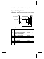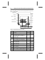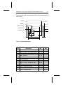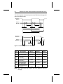
1
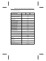
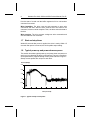
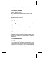
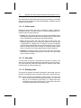
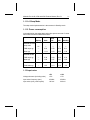
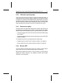
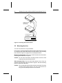
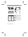
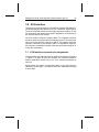
.....................................
Medalist Pro 9140
.....................................
Medalist Pro 6530
.....................................
Medalist Pro 4520
.....................................
Ultra ATA Interface Drives
.....................................
Product Manual
.....................................
................................
Medalist Pro 9140 (ST39140A)
................................
Medalist Pro 6530 (ST36530A)
................................
Medalist Pro 4520 (ST34520A)
................................
Ultra ATA Interface Drives
................................
Product Manual
................................
© 1998 Seagate Technology, Inc. All rights reserved
Publication Number: 32659-001, Rev. B, April 1998
Seagate, Seagate Technology, the Seagate logo, Medalist and the
Medalist logo are registered trademarks of Seagate Technology, Inc.
Other product names are trademarks or registered trademarks of their
owners.
Seagate reserves the right to change, without notice, product offerings
or specifications. No part of this publication may be reproduced in any
form without written permission from Seagate Technology, Inc.
Medalist Pro 9140, 6530 and 4520 Product Manual, Rev. B
iii
Contents
Introduction
. . . . . . . . . . . . . . . . . . . . . . . . . . . . . 1
Specification summary table . . . . . . . . . . . . . . . . . . . . 3
1.0 Specifications . . . . . . . . . . . . . . . . . . . . . . . . . . 5
1.1 Formatted capacity . . . . . . . . . . . . . . . . . . . . . . . 5
1.1.1 Standard configuration . . . . . . . . . . . . . . . . . . 5
1.2 Physical organization
. . . . . . . . . . . . . . . . . . . . . 6
1.3 Functional specifications . . . . . . . . . . . . . . . . . . . . 6
1.4 Physical dimensions . . . . . . . . . . . . . . . . . . . . . . 7
1.5 Seek time . . . . . . . . . . . . . . . . . . . . . . . . . . . . 7
1.6 Multisegmented cache buffer
. . . . . . . . . . . . . . . . . 7
1.7 Start and stop times . . . . . . . . . . . . . . . . . . . . . . 8
1.8 Typical power-up and power-down sequence . . . . . . . . . 8
1.9 Power-up sequence
. . . . . . . . . . . . . . . . . . . . . 9
1.9.1 Power-down sequence . . . . . . . . . . . . . . . . . . 9
1.10 Auto-park . . . . . . . . . . . . . . . . . . . . . . . . . . . 9
1.11 Power specifications . . . . . . . . . . . . . . . . . . . . . 9
1.11.1 Power management . . . . . . . . . . . . . . . . . . . 9
1.11.2 Power consumption . . . . . . . . . . . . . . . . . . 11
1.12 Input noise . . . . . . . . . . . . . . . . . . . . . . . . . 11
1.13 Environmental specifications . . . . . . . . . . . . . . . . 12
1.13.1 Ambient temperature . . . . . . . . . . . . . . . . . . 12
1.13.2 Temperature gradient . . . . . . . . . . . . . . . . . 12
1.13.3 Altitude . . . . . . . . . . . . . . . . . . . . . . . . . 12
1.13.4 Relative humidity . . . . . . . . . . . . . . . . . . . . 12
1.14 Shock . . . . . . . . . . . . . . . . . . . . . . . . . . . . 12
1.14.1 Operating shock . . . . . . . . . . . . . . . . . . . . 12
1.14.2 Nonoperating shock . . . . . . . . . . . . . . . . . . 13
1.14.3 Operating vibration . . . . . . . . . . . . . . . . . . . 13
1.14.4 Nonoperating vibration . . . . . . . . . . . . . . . . . 13
iv
Medalist Pro 9140, 6530 and 4520 Product Manual, Rev. B
1.14.5 Acoustics . . . . . . . . . . . . . . . . . . . . . . . 13
1.15 Reliability . . . . . . . . . . . . . . . . . . . . . . . . . . 14
1.16 Agency listings . . . . . . . . . . . . . . . . . . . . . . . 14
1.17 Electromagnetic Compliance for the European Union . . . 14
1.18 FCC verification . . . . . . . . . . . . . . . . . . . . . . . 15
2.0 Configuring and mounting the drive . . . . . . . . . . . . . 17
2.1 Handling and static-discharge precautions
. . . . . . . . . 17
2.2 I/O cable and connector. . . . . . . . . . . . . . . . . . . . 18
2.3 Power connector . . . . . . . . . . . . . . . . . . . . . . . 18
2.4 Options jumper block . . . . . . . . . . . . . . . . . . . . 19
2.4.1 Master/slave configuration
. . . . . . . . . . . . . . . 20
2.4.2 Alternate capacity jumper . . . . . . . . . . . . . . . . 21
2.4.3 Cable-select option . . . . . . . . . . . . . . . . . . . 21
2.4.4 Remote LED . . . . . . . . . . . . . . . . . . . . . . 21
2.5 Mounting the drive . . . . . . . . . . . . . . . . . . . . . . 22
3.0 ATA interface . . . . . . . . . . . . . . . . . . . . . . . . . 25
3.1 ATA Interface connector pin assignments . . . . . . . . . . 25
3.2 Command set
. . . . . . . . . . . . . . . . . . . . . . . . 27
3.2.1 Identify Drive command (ECH) . . . . . . . . . . . . . 29
3.2.2 Set Features command (EFH) . . . . . . . . . . . . . . 32
3.2.3 Standby timer timeout period . . . . . . . . . . . . . . 34
3.2.4 Automatic Reallocation . . . . . . . . . . . . . . . . . 34
3.2.5 S.M.A.R.T. command (B0H) . . . . . . . . . . . . . . . 35
3.3 Synchronous DMA Transfer . . . . . . . . . . . . . . . . . 36
3.3.1 Signal Line Definitions . . . . . . . . . . . . . . . . . . . 36
3.3.2 Protocol Rules . . . . . . . . . . . . . . . . . . . . . . 36
3.3.3 Error Register . . . . . . . . . . . . . . . . . . . . . . 37
Appendix. Timing diagrams . . . . . . . . . . . . . . . . . . 39
Medalist Pro 9140, 6530 and 4520 Product Manual, Rev. B
v
Figures
Figure 1. Typical startup current profile . . . . . . . . . . . . . . . . 8
Figure 2. ATA interface connector
. . . . . . . . . . . . . . . . . 18
Figure 3. Connectors . . . . . . . . . . . . . . . . . . . . . . . . 19
Figure 4. Configuration settings . . . . . . . . . . . . . . . . . . . 20
Figure 5. Connecting cable-selected drives . . . . . . . . . . . . . 22
Figure 6. Mounting dimensions . . . . . . . . . . . . . . . . . . . 23
Figure 7. ATA interface connector pin assignments
. . . . . . . . 26
Figure 8. Programmed I/O timing without IORDY . . . . . . . . . . 39
Figure 9. Programmed I/O timing with IORDY . . . . . . . . . . . 40
Figure 10. Multiword DMA timing . . . . . . . . . . . . . . . . . . 41
Figure 11. Sustained synchronous DMA burst . . . . . . . . . . . 42
vi
Medalist Pro 9140, 6530 and 4520 Product Manual, Rev. B
Medalist Pro 9140, 6530 and 4520 Product Manual, Rev. B
1
Introduction
This manual describes the functional, mechanical and interface specifications for the Medalist® Pro 9140, the Medalist Pro 6530 and the
Medalist Pro 4520 hard disc drives. The drives are referred to throughout
this manual by their model numbers, ST39140A for the Medalist Pro
9140, ST36530A for the Medalist Pro 6530, and ST34520A for the
Medalist Pro 4520.
Seagate® desktop products take a step into the future with the ST39140A,
ST36530A and ST34520A. These drives feature MR heads and EPRML
recording technology, Ultra ATA performance, 7,200-RPM technology,
segmented cache, embedded servo technology, low noise and power
management.
Ultra ATA performance means that the drive supports PIO mode 4,
multiword DMA mode 2 transfer modes and synchronous DMA mode.
When the host chooses Ultra DMA mode 2, the drive provides burst
transfer rates of up to 33.3 Mbytes per second. The multiple block
read/write feature allows the drive to store several blocks of data in its
512-Kbyte segmented cache and transfer the blocks in a single burst.
The Medalist Pro drives have other features that ensure fast data
throughput. Embedded servo technology allows the drives to position the
heads for data retrieval efficiently and accurately while eliminating the
periodic thermal recalibration that can interrupt data transfers. An intelligent controller provides data streaming: direct data transfers between
the drive and the host without microprocessor intervention. These features allow for a sustained data-transfer rate that facilitates video playback and other multimedia operations.
The drives support Active, Idle and Standby power-management modes.
Power-saving modes can be controlled by the host computer. Standby
mode reduces power consumption to 3.0 watts (typical) while retaining
drive accessibility.
Self-Monitoring, Analysis and Reporting Technology (S.M.A.R.T.) is
available on these drives. This feature is discussed on page 35. To use
the feature, you must have a BIOS, a software driver or application
software that supports S.M.A.R.T.
The ATA commands with specific applications for these drives and the
Seagate-unique commands the drives use are discussed in Section 3.0
on page 25. A complete list of the commands the drives support are found
in the table on page 27.
2
Medalist Pro 9140, 6530 and 4520 Product Manual, Rev. B
The following is a summary of the drives’ features:
Capacity
• 9.1, 6.5 and 4.5 Gbytes formatted
• LBA translation support
• Available software driver that surpasses the 528-Mbyte barrier and
4,092-cylinder barrier limited by some system BIOSs
• Available software driver that provides expanded 32-bit disk access
support for Windows 3.x
Performance
• Ultra ATA (Burst transfer rates up to 33.3 Mbytes per second)
• Supports multiword DMA mode 2, Ultra DMA mode 2, PIO mode 4
and multiple block read/write.
• 512-Kbyte segmented buffer
• 9.5-msec average read seek time
• 10.5-msec average write seek time
• Data streaming
Energy-efficiency
•
Active, Idle and Standby power-management modes
•
3.0 watt typical power dissipation rating in Standby mode
Medalist Pro 9140, 6530 and 4520 Product Manual, Rev. B
3
Specification summary table
The following table serves as a quick reference for the drives’ performance specifications. These and other specifications are discussed in
“Specifications” on page 5.
Drive specification
ST39140A ST36530A ST34520A
Guaranteed capacity (Gbytes)
(×109 bytes)
9.11
Guaranteed sectors
17,803,440 12,715,920 8,890,560
6.55
4.55
Bytes per sector
512
Sectors per track
63
Logical read/write heads
16
15
15
Logical cylinders
16,383
13,456
9,408
Physical cylinders
9,006
9,006
9,006
Physical read/write heads
8
6
4
Discs
4
3
2
Areal density (Mbits per
square inch)
Data zones
1,715.2
19
Recording density (Kbits per
inch)
179.2
Track density (tracks per inch)
9,570
Spindle speed (RPM)
7,200
Track-to-track seek time (msec
typical)
2.0
Average read seek time (msec
typical)
9.5
Average write seek time (msec
typical)
10.5
Full-stroke seek time (msec
typical)
continued
21
4
Medalist Pro 9140, 6530 and 4520 Product Manual, Rev. B
continued from previous page
Drive specification
Average latency (msec)
Internal minimum data-transfer
rate (Mbits per sec max)
ST39140A ST36530A ST34520A
4.16
193.88
External transfer rate (Mbytes
per sec max)
33.3
Cache buffer (Kbytes)
512
ECC on-the-fly (bits)
65
Height (inches max)
1.027
Width (inches max)
4.023
Depth (inches max)
5.787
Typical weight (lb)
1.5
Spinup current (max)
2.5A
Seek power (typical)
13.0W
Read/Write power (typical)
11.0W
Idle total power (typical)
11.0W
Standby/Sleep total power
(typical)
3.0W
Voltage tolerance (including
noise): +5V
± 5%
Voltage tolerance (including
noise): +12V
± 5%
Operating temperature (°C)
5° to 55°C
Medalist Pro 9140, 6530 and 4520 Product Manual, Rev. B
5
1.0 Specifications
1.1 Formatted Capacity
These drives support cylinder-head-sector (CHS) and logical-block addressing (LBA) translation modes. You can use the Identify drive (ECH)
command to verify the address modes the drives support, the number of
cylinders, sectors per track, total number of sectors, heads and other parameters. The Identify drive parameters are listed in Section 3.2.1 on page 29.
Notes:
1. DOS and FAT 16 cannot access more than 2.147 Gbytes per partition. You must create multiple partitions to access the drive’s full capacity.
2. One Mbyte equals one million bytes.
3. If the system BIOS does not support more than 4,092 cylinders, it may cause the computer to hang during startup, or it
may truncate or wrap the cylinders. To resolve this issue, the
system BIOS needs to be modified: the cylinder register or
variable must be increased from 12 bits to 16 bits to accommodate more than 4,092 cylinders.
1.1.1
Standard Configuration
CHS Mode
ST39140A
ST36530A
ST34520A
Cylinders
16,383
13,456
9,408
Heads
16
15
15
Sectors
63
63
63
Guaranteed sectors
17,803,440
12,715,920
8,890,560
Guaranteed capacity
(Gbytes)
9.11
6.55
4.55
LBA Mode
When addressing either drive in LBA mode, all blocks (sectors) are
consecutively numbered from 0 to n–1.
6
Medalist Pro 9140, 6530 and 4520 Product Manual, Rev. B
1.2 Physical organization
ST39140A
ST36530A
ST34520A
Read/write heads
8
6
4
Discs
4
3
2
1.3 Functional specifications
Interface
Ultra ATA
Recording method
EPRML (16/17 )
External data burst transfer rate:
DMA mode 2 (Mbytes per sec)
PIO mode 4 (Mbytes per sec)
Synchronous DMA mode 2
16.6
16.6
33.3
Internal minimum data-transfer rate
(Mbits per sec)
193.88
Spindle speed (RPM)
7,200 ± 0.5%
Cache size (Kbytes)
512
Bytes per sector
512
Areal density (Mbits/sq. in)
1,715.2
Data zones
19
Recording density, max (Kbits)
179.2
Track density (TPI)
9,570
Note. See Figure 8 on page 39 and Figure 9 on page 40 for PIO timing
specifications. See Figure 10 on page 41 and Figure 11 on page
42 for DMA timing specifications.
Medalist Pro 9140, 6530 and 4520 Product Manual, Rev. B
7
1.4 Physical dimensions
The mounting dimensions are shown in Figure 6 on page 23.
Height, max
1.027 inch (26.1 mm)
Width, max
4.010 inches (101.9 mm)
Depth, max
5.787 inches (146.1 mm)
Weight
1.5 lb (0.68 Kg)
1.5 Seek time
Seek value is the interval between the time the actuator begins to move
and the time the head has settled over the target track. Seek time is a
true statistical average of at least 10,000 measurements of seek time.
All measurements are taken under nominal conditions of temperature
and voltage with the drive mounted horizontally. The specifications in the
table below are defined as follows:
• Track-to-track seek time is the average of all possible single-track
seeks in both directions.
• Average seek time is measured by executing seeks in both directions
between random cylinders.
• Full-stroke seek time is half the time needed to seek from track 0 to
the maximum track and back to track 0.
Track-to-track
seek time (typ)
Average/typical
seek time
Full-stroke
seek time (typ)
Average
latency
2.0 msec seek
2.5 msec read
3.5 msec write
9.5 msec read
10.5 msec write
21.0 msec seek
22.0 msec read
23.5 msec write
4.16 msec
Note. Host overhead varies between systems and cannot be specified.
Drive internal overhead is measured by issuing a no-motion seek.
Overhead is typically less than 0.5 msec.
1.6 Multisegmented cache buffer
The Medalist Pro ST39140A, ST36530A, and ST34520A drives are
available with a 512-Kbyte, multisegmented cache buffer that improves
performance by reducing access times.
Read look-ahead. The drive uses the read segments to store additional
logical sectors, after the last requested sector, into a buffer before the
computer requests the additional sectors. The cache buffer stores data
8
Medalist Pro 9140, 6530 and 4520 Product Manual, Rev. B
from the start of a read until the buffer segment is full or until another
command is received.
Write immediate. The drive uses the write segment to store write
commands and data. After the drive receives all of the data for the
command, it issues a write complete. Then, the drive writes the data to
the disc.
Write merging. The drive accepts contiguous write commands and
executes them as one command.
1.7 Start and stop times
Within 20 seconds after power is applied, the drive is ready. Within 15
seconds after power is removed, the drive spindle stops rotating.
1.8 Typical power-up and power-down sequence
This section describes typical power-up and power-down sequences to
assist you in evaluating the drive’s performance. They are not performance specifications. A typical startup current profile is shown in Figure 1.
Startup current profiles are unique for each drive.
Current (Amps)
2.5
2.0
1.5
1.0
0.5
0
0
2
4
6
8
10
Time (seconds)
Figure 1. Typical startup current profile
12
14
16
Medalist Pro 9140, 6530 and 4520 Product Manual, Rev. B
9
1.9 Power-up sequence
1. Power is applied to the drive.
2. The spindle motor reaches operating speed in about 4 seconds.
3. The airvane actuator-lock releases the actuator.
4. The drive synchronizes to servo pattern.
5. Calibration routines are performed.
6. The heads move back to track 0 and the drive is ready.
5.
1.9.1
Power-down sequence
Caution. Do not move the drive until the motor has come to a complete
stop.
1. The power is turned off.
2. The read/write heads automatically move to the landing zone, which
is inside the maximum data cylinder.
3. The airvane actuator-lock mechanism locks the arm. This completes
the power-down sequence.
4. Within 15 seconds, the drive stops rotating.
1.10 Auto-park
During power-down, the read/write heads automatically move to the
landing zone. The heads park inside the maximum data cylinder and the
airvane actuator-lock engages. When power is applied, the heads recalibrate to track 0.
1.11 Power specifications
1.11.1 Power management
The drive supports Active, Idle and Standby power-management modes.
The power-management commands the drive supports are listed in the
table on page 27. The table on page 11 shows the average typical power
consumption rates for each power-management mode. The test criteria
for each mode is defined on the following page. The Idle and Standby
timers are disabled at the factory.
10
Medalist Pro 9140, 6530 and 4520 Product Manual, Rev. B
All measurements were taken at the drive power connector. A true RMS
meter is used to measure all modes except Standby. A DMM is used for
Standby measurements.
1.11.1.1 Active mode
During the Active mode, the drive is involved in spinup, seeking or
read/write activities. The table on page 11 shows the typical power-consumption rates for these activities.
• Spinup. The drive enters the Spinup mode from the Standby mode
and brings the spindle and discs up to operating speed. Power in this
mode is defined as the peak power after starting spinup.
• Seek. The drive enters the Seek mode from the Idle mode. The
read/write heads are moved to a specific location on the disc surface
in preparation for reading from or writing to the disc. Read/write
electronics are powered down but servo electronics are active. Typical
power is defined as the power average of executing random seeks
with a 2-revolution (22.2 msec) dwell between Seek commands.
• Read/write. Read/write mode is entered from Idle mode. Read/write
electronics are activated and the servo is on track. The drive reads
from or writes to the disc.
1.11.1.2 Idle mode
The Idle mode is entered 1 minute after the last disc I/O activity. The
motor is up to speed and the actuator is repositioned once every minute.
The drive enters Idle mode from either Active or Standby mode, when
the host issues an Idle command only.
1.11.1.3 Standby mode
The spindle is stopped, the heads are parked in the landing zone, the
actuator is latched and some of the drive electronics are powered down.
Note. When recovering from Standby or Sleep mode, you must allow
the drive to post ready before reporting a timeout. The drive can
take up to 20 seconds to post ready. In a master and slave
configuration, the master can wait up to 31 seconds for the slave
to complete diagnostics before posting ready.
Medalist Pro 9140, 6530 and 4520 Product Manual, Rev. B
11
1.11.1.4 Sleep Mode
The sleep mode implementation is the same as in Standby mode.
1.11.2 Power consumption
In the table below, the values apply at the drive power connector. Current
was measured with an RMS DC ammeter.
Spinup
Seek
Amps max
2.5
—
RMS amps typ
—
Watts typ
Read/
write
Idle
Standby
—
—
—
0.93
0.78
0.76
0.11
—
11.12
9.33
9.09
1.38
RMS amps typ
—
0.38
0.33
0.38
0.32
Watts typ
—
1.88
1.67
1.91
1.62
—
13.0
11.0
11.0
3.0
Current at +12V
Current at +5V
Power
Total watts typ
1.12 Input noise
+5V
+12V
Voltage tolerance (including noise)
± 5%
± 5%
Input noise frequency (max)
25 MHz
25 MHz
Input noise (max, peak-to-peak)
100 mV
240 mV
12
Medalist Pro 9140, 6530 and 4520 Product Manual, Rev. B
1.13 Environmental specifications
1.13.1 Ambient temperature
Operating
Nonoperating
5° to 55°C (41° to 131°F)
–40° to 70°C (–40° to 158°F)
Note. The system must provide sufficient airflow to maintain a
surface temperature of the aluminum base below 60°C.
1.13.2 Temperature gradient
Operating
Nonoperating
20°C per hour (36°F per hour)
30°C per hour (54°F per hour)
1.13.3 Altitude
Operating
–1,000 ft. to 10,000 ft. (–305 m to 3,048 m)
Nonoperating
–1,000 ft. to 40,000 ft. (–305 m to 12,192 m)
1.13.4 Relative humidity
Operating
Maximum operating
gradient
Nonoperating
8% to 90% noncondensing
Maximum wet bulb 29.4°C (85°F)
30% per hour
5% to 95% noncondensing
Maximum wet bulb 40°C (95°F)
1.14 Shock
All shock and vibration specifications assume that the drive is mounted
securely with input shock applied at the drive mounting screws. Shock
and vibration may be applied in the X,Y or Z axis.
1.14.1 Operating shock
These drives comply with the performance levels specified in this document when subjected to maximum operating shock of 10.0 Gs (based on
Medalist Pro 9140, 6530 and 4520 Product Manual, Rev. B
13
half-sine shock pulses of 11 msec, as specified in MIL-STD-202F).
Shocks are not to be repeated more than two times per second.
1.14.2 Nonoperating shock
The nonoperating shock level that the drive can experience without
incurring physical damage or degradation in performance when subsequently put into operation is 200 Gs (based on repetitive half-sine
shock pulses of 2-msec duration, as defined in MIL-STD-202F).
1.14.3 Operating vibration
The following table lists the maximum vibration levels that the drive may
experience while meeting the performance standards specified in this
document.
5–22 Hz
22–350 Hz
0.020-inch displacement (peak to peak)
0.50 Gs acceleration (zero to peak)
1.14.4 Nonoperating vibration
The following table lists the maximum nonoperating vibration that the
drive may experience without incurring physical damage or degradation
in performance when put into operation.
5–22 Hz
22–350 Hz
0.081-inch displacement (peak to peak)
2.00 Gs acceleration (zero to peak)
1.14.5 Acoustics
This table shows the overall A-weighted acoustic sound power and sound
pressure levels for the drives. All measurements are generally consistent
with ISO document 7779. Acoustic measurements are taken under
essentially free-field conditions over a reflecting plane. The drive is
oriented with the top cover up for all tests.
Overall A-weighted
Value
Idle
Seek
Sound power, (bels)
3.9 (typ), 4.2 (max)
4.4 (typ), 4.7 (max)
Sound pressure, (dBA)
29 (typ), 32 (max)
31 (typ), 34 (max)
14
Medalist Pro 9140, 6530 and 4520 Product Manual, Rev. B
1.15 Reliability
Read error rates are measured with automatic retries and data correction
with ECC enabled and all flaws reallocated. The mean time between
failures (MTBF) is measured at nominal power at sea level with an
ambient temperature of 25°C.
Nonrecoverable read errors
1 per 1014 bits transferred
Seek errors
1 per 107 physical seeks
Contact start/stops
30,000 cycles
MTBF
400,000 power-on hours
Service life
5 years
1.16 Agency listings
The drives are listed by agencies as follows:
• Recognized in accordance with UL478 and UL1950
• Certified to CSA C22.2 No. 220-M1986 and CSA C22.2 No. 950
• Certified to VDE 0805/05.90 and EN 60950/1.88 as tested by VDE
1.17 Electromagnetic Compliance for the European
Union
If this model has the CE Marking, it complies with the European Union
requirements of the Electromagnetic Compatibility Directive 89/336/EEC
of 03 May 1989 as amended by Directive 92/31/EEC of 28 April 1992
and Directive 93/68/EEC of 22 July 1993.
Seagate uses an independent laboratory to confirm compliance to the
above directives. The drive was tested in a representative system for
typical applications. The selected system represents the most popular
characteristics for test platforms. The system configurations include:
• 486, Pentium, and PowerPC microprocessors
• 3.5-inch floppy disc drives
• Keyboard
• Monitor/display
Although the test system with this Seagate model complies to the
directives, we cannot guarantee that all systems will comply. The computer manufacturer or system integrator should confirm EMC compliance
Medalist Pro 9140, 6530 and 4520 Product Manual, Rev. B
15
and provide CE Marking for their product. The drive is not meant for
external use (without properly designed enclosure, shielded I/O cable,
etc.), and a terminator should be used on all unused I/O ports.
1.18 FCC verification
The Medalist Pro Ultra ATA interface drives are intended to be contained
solely within a personal computer or similar enclosure (not attached to
an external device). As such, a drive is considered to be a subassembly
even when individually marketed to the customer. As a subassembly, no
Federal Communications Commission authorization, verification or certification of the device is required.
Seagate Technology, Inc. has tested these drives in an enclosure as
described above to ensure that the total assembly (enclosure, disc
drives, motherboard, power supply, etc.) does comply with the limits for
a Class B computing device, pursuant to Subpart J of Part 15 of the FCC
rules. Operation with noncertified assemblies is likely to result in interference to radio and television reception.
Radio and television interference. This equipment generates and uses
radio frequency energy and, if not installed and used in strict accordance
with the manufacturer’s instructions, may cause interference to radio and
television reception.
This equipment is designed to provide reasonable protection against
such interference in a residential installation. However, there is no
guarantee that interference will not occur in a particular installation. If this
equipment does cause interference to radio or television, which can be
determined by turning the equipment on and off, you are encouraged to
try one or more of the following corrective measures:
• Reorient the receiving antenna.
• Move the device to one side or the other of the radio or TV.
• Move the device farther away from the radio or TV.
• Plug the equipment into a different outlet so that the receiver and
computer are on different branch outlets.
If necessary, you should consult your dealer or an experienced radio/television technician for additional suggestions. You may find helpful the
following booklet prepared by the Federal Communications Commission:
How to Identify and Resolve Radio-Television Interference Problems.
This booklet is available from the Superintendent of Documents, US
Government Printing Office, Washington, DC 20402. Refer to publication
number 004-000-00345-4.
16
Medalist Pro 9140, 6530 and 4520 Product Manual, Rev. B
Note. This digital apparatus does not exceed the Class B limits for radio
noise emissions from computer equipment as set out in the radio
interference regulations of the Canadian Department of communications.
Le présent appareil numérique n′émet pas de bruits radioélectriques dépassant les limites applicables aux appareils numériques
de Classe B prescrites dans le règlement sur le brouillage radioélectrique édicté par le Ministère des Communications du
Canada.
Sicherheitsanleitung
1. Das Gerrät ist ein Einbaugerät, das für eine maximale Umgebungstemperatur von 50°C vorgesehen ist.
2. Zur Befestigung des Laufwerks werden 4 Schrauben 6-32 UNC-2A
benötigt. Bei seitlicher Befestigung darf die maximale Länge der
Schrauben im Chassis nicht mehr als 5,08 mm und bei Befestigung
an der Unterseite nicht mehr als 5,08 mm betragen.
3. Als Versorgungsspannugen werden benötigt:
+5V æ 5% 0.55A
+12V æ 5% 0.35A (2.0A fur ca. 30 Sek. fur ± 10%)
4. Die Versorgungsspannung muss SELV entsprechen.
5. Alle Arbeiten an der Festplatte dürfen nur von ausgebildetem Servicepersonal durchgeführt werden. Bitte entfernen Sie nicht die Aufschriftenschilder des Laufwerkes.
6. Der Einbau des Laufwerkes muss den Anforderungen gemäss DIN
IEC 950 VDE 0805/05.90 entsprechen.
Medalist Pro 9140, 6530 and 4520 Product Manual, Rev. B
17
2.0 Configuring and mounting the drive
This section contains the specifications and instructions for configuring
and mounting the drive.
2.1 Handling and static-discharge precautions
After you unpack the drive, and before you install it in a system, be careful
not to damage it through mishandling. Observe the following standard
handling and static-discharge precautions:
Caution:
• Keep the drive in its static-shielded bag until you are ready to complete
the installation. Do not attach any cables to the drive while it is in its
static-shielded bag.
• Before handling the drive, put on a grounded wrist strap, or ground
yourself frequently by touching the metal chassis of a computer that
is plugged into a grounded outlet. Wear a grounded wrist strap
throughout the entire installation procedure.
• Handle the drive by its edges or frame only.
• The drive is extremely fragile—handle it with care. Do not press down
on the drive top cover.
• Always rest the drive on a padded, antistatic surface until you mount
it in the computer.
• Do not touch the connector pins or the printed circuit board.
• Do not remove the factory-installed labels from the drive or cover them
with additional labels. Removal voids the warranty. Some factory-installed labels contain information needed to service the drive. Other
labels are used to seal out dirt and contamination.
18
Medalist Pro 9140, 6530 and 4520 Product Manual, Rev. B
2.2 I/O cable and connector
The drive uses a 40-pin, male I/O connector with two rows of twenty pins
each and a notch for keying. Pin 20 is removed for keying purposes. A
drawing of the I/O connector is shown in Figure 2. Pin 1 is located near
the 4-pin power connector when the I/O connector is mounted.
0.100 ± 0.010
0.235 ± 0.025
pin 1
0.70 ± 0.010
0.025
± 0.002
0.230 ± 0.003
0.025 ± 0.002
0.100 typ
0.160
0.070 ± 0.010
1.90
2.00
Figure 2. ATA interface connector
The table below lists recommended parts for the mating connector. You
can use equivalent parts.
Part
Description
3M part number
Connector
40-pin
3M-3417-7000
Connector
40-pin
3M-3448-2040
Flat cable
AWG28 (stranded)
3M-3365-40
To ensure the integrity of your data, use a 40-connector, nonshielded I/O
cable with a maximum length of 18 inches (46 centimeters).
2.3 Power connector
The drive uses a standard 4-pin, male power connector. We recommend
the following part number or their equivalents for the mating connector.
Part
Description
Part number
Connector
Housing
AMP 1-480424-0
Connector
Pin (loose piece)
AMP 60619-4
Connector
Pin (reel)
AMP 6117-4
Cable
18 AWG
—
Medalist Pro 9140, 6530 and 4520 Product Manual, Rev. B
19
2.4 Options jumper block
The options jumper block (J5), shown in Figure 3, is used to configure
the drives for operation. It is the 8-pin dual header between the I/O
connector and the power connector. Pin 1 is located next to the power
connector and is farthest from the printed circuit board. It accepts
0.1-inch jumpers. The options jumper block is used to:
• Configure the drive for single-drive operation.
• Configure the drive as master with an ATA-compatible slave.
• Configure the drive as the slave.
• Configure the drive for alternate capacity.
• Configure the drive for cable select.
• Install a remote LED.
The jumper settings for these options are shown in Figure 4 on page 20.
Interface
connector
Pin 1
Pin 1
(J5)
Standard
power connector
1 2 3 4
Circuit board
+5V
+5V return
+12V return
+12V
Figure 3. Connectors
20
Medalist Pro 9140, 6530 and 4520 Product Manual, Rev. B
Options jumper block (J5)
One drive only or
master
Drive is slave
Cable select
Alternate capacity
(AC)
Remote LED
connection
Spare jumper
G E C A
H F D B
Circuit Board
Figure 4. Configuration Settings
2.4.1
Master/slave configuration
Use the following settings to configure the drive as a master or slave.
One drive only or master. The drive is configured at the factory for a
master drive with a jumper installed on pins G and H. The spare jumper
on pins A and C is a spare and does not affect drive operation.
Drive as slave. Remove all the jumpers if you are installing your drive
as a slave.
Medalist Pro 9140, 6530 and 4520 Product Manual, Rev. B
2.4.2
21
Alternate capacity jumper
This jumper lowers the drive capacity by setting the default translation to
4,092 cylinders and causes the drive to appear to your BIOS as having
a capacity of 2.1 Gbytes. Some BIOSs that only auto-detect may require
this jumper. Place a jumper on pins A and B of the J5 options jumper
block to enable this option. When installing this jumper, you may need
third-party partitioning software to achieve full capacity of the drive.
2.4.3
Cable-select option
Computers that use cable-select determine the master and slave drives
by selecting or deselecting pin 28, CSEL, on the interface bus. Master
and slave drives are determined by their physical position on the cable.
• The drive plugged into the I/O connector that carries the CSEL signal
is the master.
• The drive plugged into the I/O connector that does not carry the CSEL
signal is the slave.
To configure the drives for computers that use cable select:
• Install a jumper on pins E and F as shown in Figure 4 on page 20.
• Connect the drives to the cable as shown in Figure 5 on page 22.
2.4.4
Remote LED
You can connect a remote LED to pins C(–) and D(+) of the options
jumper block (J5). Do not install a shunt jumper on these pins.
Because the jumper block uses a 0.1-inch connector, you may need to
replace the current connector. Use Seagate connector part number
10562-001 or an equivalent.
22
Medalist Pro 9140, 6530 and 4520 Product Manual, Rev. B
Slave
CSEL not carried
to pin 28 of
this connector
Master
Pin 28 grounded
at computer
Computer
Figure 5. Connecting cable-selected drives
2.5 Mounting the drive
You can mount the drive in any orientation.
Use the set of mounting guidelines below that are appropriate to the type
of mounting holes used: either bottom mounting holes or side mounting
holes. Refer to Figure 6 on page 23 for mounting dimensions.
Bottom mounting holes. Insert four 6-32 UNC screws in the four bottom
mounting holes as shown in Figure 6.
Caution. Do not insert the bottom mounting screws more than 0.20
inches (6 turns) into the drive frame.
Side mounting holes. Use four 6-32 UNC screws in four of the six
available side mounting holes as shown in Figure 6. Use two mounting
holes on each side of the drive.
Caution. Do not insert the side mounting screws more than 0.20 inches
(6 turns) into the drive frame. If you use a screw that is too
long, you may damage the drive’s circuit board.
Medalist Pro 9140, 6530 and 4520 Product Manual, Rev. B
C
3
23
J
G
4 M
D
1
F
E
K
A
H
2
5
B
Dimension Table
Inches
A
B
C
D
E
F5
G
H
J
K
M
± 0.026
± 0.010
± 0.012
± 0.010
± 0.020
± 0.010
+ 0.010
– 0.005
1.750 ± 0.010
3.750 ± 0.010
1.625 ± 0.020
0.143*
5.754
4.00
1.007
2.362
0.620
4.000
0.250
Millimeters
146.15
101.60
25.58
60.00
15.75
101.60
6.35
± 0.66
± 0.25
± 0.30
± 0.25
± 0.50
± 0.25
+ 0.25
– 0.12
44.45 ± 0.25
95.25 ± 0.25
41.27 ± 0.50
3.63*
1 Mounting holes three on each side, 6-32 UNC.
Max screw length into side of drive 0.15 in. (3.81
mm). Screw tightening torque 6.0 in-lb (0.675
NM) max with minimum thread engagement of
0.12 in. (3.05 mm).
2 Mounting holes four on bottom, 6-32 UNC. Max
screw length into bottom of drive 0.15 in. (3.81
mm). Screw tightening torque 6.0 in-lb (0.675 NM)
max with minimum thread engagement of 0.12 in.
(3.05 mm).
3 Power and interface connectors can extend past
the “A” dimension by 0.040 in. (1.02 mm).
4 Centerline of pad for Pin 1 of power connector.
*Dimensions to Pin 1 of each connector are
nominal values.
Figure 6. Mounting dimensions
24
Medalist Pro 9140, 6530 and 4520 Product Manual, Rev. B
Medalist Pro 9140, 6530 and 4520 Product Manual, Rev. B
25
3.0 ATA Interface
The drives use an ATA interface. The interface complies with ANSI ATA
(AT Attachment) Interface Document X3T13.1153 D Rev. 9 specification.
The ATA commands that the drives support are listed on pages 27 and
28. Commands and features with specific applications for these drives
are also discussed in this section.
The ATA interface consists of single-ended, TTL-compatible receivers
and drivers that use an asynchronous interface protocol. The drivers can
sink up to 24 mA and drive a load up to 300 pF. The integrity of the ATA
interface is affected by the interface cable. It is designed to support a
40-conductor, nonshielded interface cable with a maximum length of 18
inches (46 centimeters).
3.1 ATA Interface connector pin assignments
The signal name and signal direction for each I/O connector pin is shown
in Figure 7 on page 26. See the Seagate ATA Interface Reference
Manual, publication number 36111-xxx, for a complete description of
each pin.
Signal names are shown in upper-case letters. If the signal name is
followed by a minus sign (–), the signal is active low. Otherwise, the signal
is active high.
26
Medalist Pro 9140, 6530 and 4520 Product Manual, Rev. B
Drive pin #
Signal name
1
2
3
4
5
6
7
8
9
10
11
12
13
14
15
16
17
18
19
20
21
22
23
Reset–
Ground
DD7
DD8
DD6
DD9
DD5
DD10
DD4
DD11
DD3
DD12
DD2
DD13
DD1
DD14
DD0
DD15
Ground
(removed)
DMARQ
Ground
DIOW–:
STOP
Ground
DIOR–:
HDMARDY–:
HSTROBE
Ground
IORDY:
DDMARDY–:
DSTROBE
CSEL
DMACK–
Ground
INTRQ
IOCS16–
DA1
PDIAG–
DA0
DA2
CS0–
CS1–
DASP–
Ground
24
25
26
27
28
29
30
31
32
33
34
35
36
37
38
39
40
Host pin # and signal description
1
2
3
4
5
6
7
8
9
10
11
12
13
14
15
16
17
18
19
20
21
22
23
24
25
26
27
28
29
30
31
32
33
34
35
36
37
38
39
40
Hardware Reset
Ground
Host Data Bus Bit 7
Host Data Bus Bit 8
Host Data Bus Bit 6
Host Data Bus Bit 9
Host Data Bus Bit 5
Host Data Bus Bit 10
Host Data Bus Bit 4
Host Data Bus Bit 11
Host Data Bus Bit 3
Host Data Bus Bit 12
Host Data Bus Bit 2
Host Data Bus Bit 13
Host Data Bus Bit 1
Host Data Bus Bit 14
Host Data Bus Bit 0
Device Data (15:0)
Ground
(No Pin)
DMA Request
Ground
Host I/O Write:
Stop Ultra DMA Burst
Ground
Host I/O Read:
Host Ultra DMA Ready/
Host Ultra DMA Data Strobe
Ground
I/O Channel Ready
Device Ultra DMA Ready
Device Ulta DMA Data Strobe
Cable Select
DMA Acknowledge
Ground
Device Interrupt
Host 16 Bit I/O
Host Address Bus Bit 1
Passed Diagnostics
Device Address (2:0)
Device Address (2:0)
Chip Select (1:0)
Chip Select (1:0)
Drive Active / Slave Present
Ground
Pins 28, 34 and 39 are used for master-slave communication (details shown below).
Drive 1 (slave)
28
34
39
Drive 0 (master)
28
34
39
CSEL
PDIAG–
DASP–
Figure 7. Ultra ATA interface connector pin assignments
Host
28
34
39
Medalist Pro 9140, 6530 and 4520 Product Manual, Rev. B
27
3.2 Command set
This section lists all of the ATA commands the drives use. Only the
commands with unique implementation for the drives are discussed in
this manual. For information about the ATA interface, refer to
X3T13.1153D Rev. 9, Information Technology—AT Attachment-4 Interface specification.
The table below lists all commands implemented in the drives. It uses
the following abbreviations:
FR
Features register
SC
Sector Count register
SN
Sector Number register
CY
Cylinder register
DH
Drive/Head register
n
This register does not contain a valid parameter for this
command.
y
This register contains a valid parameter for this command. In
the Drive/Head register, both the drive and head parameters
are valid for this command.
D
The Drive/Head register contains a valid drive parameter for
this command. The head parameter is not valid for this
command.
Note. Read DMA, Read Long, Read Sector, Read Verify Sector, Write
DMA, Write Long and Write Sector support with retry and without
retry commands.
Command name
Parameters used
Command
code (in hex) FR SC SN CY DH
Active and Set Idle Timer
FB
n
y
n
n
D
Active Immediate
F9
n
n
n
n
D
Check Idle Mode
FD
n
y
n
n
D
98, E5
n
y
n
n
D
Execute Drives Diagnostic
90
n
n
n
n
D
Identify drives
EC
n
n
n
n
D
97, E3
n
y
n
n
D
Check Power Mode
Idle
continued
28
Medalist Pro 9140, 6530 and 4520 Product Manual, Rev. B
continued from previous page
Command name
Idle and Set Idle Timer
Parameters used
Command
code (in hex) FR SC SN CY DH
FA
n
y
n
n
D
95, F8, E1
n
n
n
n
D
91
n
y
n
n
y
Read DMA
C8, C9
—
y
y
y
y
Read Long
22, 23
n
y
y
y
y
Read Multiple
C4
n
y
y
y
y
Read Sector
20, 21
n
y
y
y
y
Read Sector Buffer
E4
n
n
n
n
D
Read Verify Sector
40, 41
n
y
y
y
y
Recalibrate
1X
n
n
n
n
D
Seek
7X
n
n
y
y
y
Set Features
EF
y
n
n
n
D
Set Multiple Mode
C6
n
y
n
n
D
99, E6
n
n
n
n
D
y
y
n
y
y
Idle Immediate
Initialize Drive Parameters
Sleep
S.M.A.R.T.
B0
Standby
96, E2
n
n
n
n
D
Standby Immediate
94, E0
n
n
n
n
D
Write DMA
CA, CB
—
y
y
y
y
Write Long
32, 33
n
y
y
y
y
Write Multiple
C5
n
y
y
y
y
Write Sector
30, 31
n
y
y
y
y
E8
n
n
n
n
D
Write Sector Buffer
Medalist Pro 9140, 6530 and 4520 Product Manual, Rev. B
3.2.1
29
Identify Drive command (ECH)
The Identify Drive parameters for the drives are listed in the table below.
Note. If the alternate capacity jumper is installed on the drive, the drive
capacity is reduced in Word 1 to 4,092 cylinders.
Word
Description
ST Value
0
Configuration
045AH
1
Number of logical
cylinders
ST39140A = 16,383
ST36530A = 13,456
ST34520A = 9,408
2
Reserved
0000
3
Number of logical heads
ST39140A = 16
ST36530A = 15
ST34520A = 15
4
Vendor-specific
35,141
5
Vendor-specific
580
6
Number of logical sectors 63
per track
Vendor-specific
0000
Serial number (20 ASCII
characters)
drive-unique
20
Vendor-specific
3
21
Vendor-specific
896
22
ECC bytes (R/W Long)
0004H
23–26
Firmware revision
(8 ASCII characters)
drive-unique
27–46
Model number (40 ASCII
characters)
ST39140A
ST36530A
ST34520A
47
Vendor-specific
8010H
48
Reserved
0000
49
Capabilities
0B01H
50
Reserved
0000
7–9
10–19
continued
30
Medalist Pro 9140, 6530 and 4520 Product Manual, Rev. B
continued from previous page
Word
Description
ST Value
51
PIO data-transfer cycle
timing mode
0200H
52
Obsolete
0200H
53
Current valid
0007H words 54–58, 64–70
and 85–86 are valid
54
Number of current logical ST39140A = 16,383
cylinders
ST36530A = 13,456
ST34520A = 9,408
55
Number of current logical ST39104A = 16
heads
ST36530A = 15
ST34520A = 15
56
Number of current
sectors
63
57–58
Current capacity in
sectors (CHS)
ST39140A = 16,514,064
ST36530A = 12,715,040
ST34520A = 8,890,560
59
60–61
xxH = Current setting for 0000s
number of sector that can
be transferred per
interrupt on Read/Write
Multiple command
Total number of userST39140A = 17,803,440
addressable LBA sectors ST36530A = 12,715,040
ST34520A = 8,890,560
62
Obsolete
0000
63
Multiword DMA transfer
mode active
0107H
Mode 0 is active
Modes 0, 1, and 2 supported
64
Advanced PIO transfer
mode supported
0003H
Modes 3 and 4 supported
65
Minimum multiword DMA 120 nsec
transfer cycle time per
word
66
Manufacturer
recommended multiword
DMA transfer cycle time
120 nsec
Medalist Pro 9140, 6530 and 4520 Product Manual, Rev. B
Word
Description
31
ST Value
67
Minimum PIO transfer
cycle time without flow
control
120 nsec
68
Minimum PIO transfer
with IORDY flow control
120 nsec
Reserved
0000
80
Major version number
0007H
Modes 1, 2, and 3 supported
81
Minor version number
0000
82
Command set support
7069H
83
Command set support
4000H
84
Command set/feature
supported extension
0
85–86
Command set/feature
enabled
0
87
Command set/feature
default
0
88
Ultra DMA mode
0007H
69–79
89–127
Reserved
128
Security status
129–159
Vendor-specific
160–255
Reserved
0000
32
3.2.2
Medalist Pro 9140, 6530 and 4520 Product Manual, Rev. B
Set Features command (EFH)
The Set Features command (command code EFH) allows you to enable
and disable the multisegmented cache and automatic reallocation features and to identify the transfer modes the drives use. The multisegmented buffer consists of read look-ahead and write-immediate and
write-merging features. The table below lists the features the drives
support. The features that are set to default by the factory are indicated
in the Feature column.
To use the command:
1. Write the Feature value to the Features register.
2. Write the Set Features command to the command register.
Note. If the value in the Features register is not supported or is invalid,
the drives post an Aborted Command error.
At power-on or after a hard reset, the feature selections are restored to
the factory-default values.
The table below shows alterable features that the drives support. Values
that are preset at the factory are indicated as default in the feature
description.
Feature Value
Feature
02H
Enable write cache (default)
03H
Set transfer mode
04H
Enable read automatic reallocation (default)
55H
Disable read look-ahead cache
82H
Disable write cache
84H
Disable read automatic reallocation
AAH
Enable read look-ahead cache (default)
Medalist Pro 9140, 6530 and 4520 Product Manual, Rev. B
33
3.2.2.1 PIO and DMA Data-Transfer Modes
You can set the multiword DMA mode and identify the PIO data-transfer
mechanism and transfer mode with the Set Features command. To set
the multiword DMA mode:
1. Write Set Features command value 03H (Set Data Transfer mode) to
the Features register.
2. Write a transfer types value to the Sector Count register. The upper 5
bits of this value define the type of data transfer, and the lower 3 bits
encode the mode value.
This changes word 63 of the Identify Drive command to the mode you
enter in the Sector Count register.
The following table identifies allowable transfer types values:
Data-Transfer Mechanism
Mechanism name
Transfer Types value
Mode
value
Data
Lower 3 bits
Upper 5 bits
PIO Transfer Mode (default)
2
00000
000
PIO Transfer Mode: Disable
IORDY Set PIO Mode = 2
2
00000
001
PIO Flow Control Transfer
Mode: Set PIO Mode = 0
0
00001
000
PIO Flow Control Transfer
Mode: Set PIO Mode = 1
1
00001
001
PIO Flow Control Transfer
Mode: Set PIO Mode = 2
2
00001
010
PIO Flow Control Transfer
Mode: Set PIO Mode = 3
3
00001
011
PIO Flow Control Transfer
Mode: Set PIO Mode = 4)
4
00001
100
00010
nnn
0
00100
000
1
00100
001
2
00100
010
Synchronous DMA Mode
0
01000
nnn
Reserved
—
10000
nnn
Obsolete
Multiword DMA Mode
Note. If the drive does not support a commanded mode, it returns a 04
aborted command error.
34
3.2.3
Medalist Pro 9140, 6530 and 4520 Product Manual, Rev. B
Standby timer timeout period
The Idle command and Standby command Sector Count registers are
used to activate the Standby timer. The host can enable the Standby
timer by placing a value in the sector-count register of the Idle command
or Standby command. The value corresponds to a predetermined period
of drive inactivity. The table below lists the values the Seagate drives use
and their corresponding timeout period.
Sector Count Register contents
Corresponding timeout period
0 (0H)
Timeout disabled
1–12 (1H–CH)
value = 60 seconds
13–240 (DH–F0H)
(value * 5) seconds
241–251 (F1H–FBH)
(value – 240) * 30 minutes
252 (FCH)
21 minutes
253 (FDH)
8 hours
254 (FEH)
Reserved
255 (FFH)
21 minutes 15 seconds
The drives are shipped with the Standby timer disabled.
3.2.4
Automatic Reallocation
This feature allows the drive to identify grown media defects and to
reallocate the sector without host intervention using both read and write
automatic reallocation.
You can disable read reallocation by using the Set Features command
Disable Read Automatic Reallocation, feature value 84H. This feature is
not used for the Read Long command.
You can disable write reallocation, in addition to write cache, by using
the Set Feature command Disable Write Cache, feature value 82H. This
feature is not implemented for the Write Long command.
Medalist Pro 9140, 6530 and 4520 Product Manual, Rev. B
3.2.5
35
S.M.A.R.T. command (B0H)
Self-Monitoring, Analysis and Reporting Technology (S.M.A.R.T.) is an
emerging technology that provides near-term failure prediction for disc
drives. When S.M.A.R.T. is enabled, the Seagate drive monitors predetermined attributes within itself that are susceptible to degradation over
time. S.M.A.R.T. makes a status report available so that the host can
prompt the user to back up the drive if self-monitoring determines that a
failure is likely. Not all failures are predictable. S.M.A.R.T. predictability
is limited to only the attributes that the drive can monitor.
The S.M.A.R.T. feature is disabled at the factory. You must have a BIOS,
software driver or application software that supports S.M.A.R.T. to
enable this feature. The table below shows the S.M.A.R.T. command
codes the Seagate drives use.
Note. To implement a S.M.A.R.T. command, the host must write the
value 0x4F to Cylinder_lo register and the value 0xC2 to the
Cylinder_hi register at the same time it writes the S.M.A.R.T.
command code to the Features register. If these values are not
included with the command code, the command is aborted and
0x04 (abort) is written to the Error register.
Command code Feature description
D2H
Enable/disable attribute autosave
D8H
Enable operation
D9H
Disable operation
DAH
Return S.M.A.R.T. status
36
Medalist Pro 9140, 6530 and 4520 Product Manual, Rev. B
3.3 Synchronous DMA Transfer
3.3.1
Signal Line Definitions
Some existing ATA signal lines are redefined during the Synchronous
DMA protocol to provide new functions. If the Synchronous DMA transfer
mode was previously chosen by the Set Features, the ATA signal lines
change from the old to new definitions as soon as the host allows for a
DMA burst. The drive detects this change upon assertion of the –DMACK
line. These lines revert back to their original definitions upon the deassertions of –DMACK at the termination of the DMA burst.
Signal Line Definitions
Pin
New Definitions
Old Definitions
21
DMARQ
DMARQ
29
–DMACK
–DMACK
27
25
–DMACK
IORDY on write commands
–DIOR on read commands
25
27
STROBE
–DIOR on write commands
IORDY on read commands
23
STOP
–DIOW
Note. DMARQ and –DMACK signal lines remain unchanged. This ensures backward compatibility with PIO modes.
3.3.2
Protocol Rules
The general rules of the Synchronous DMA Transfer Protocol are as
follows:
• A DMA burst is defined as the period from an assertion of –DMACK
to subsequent deassertion of –DMACK.
• A receiver must be prepared to receive at least two words of data
whenever it enters or resumes a burst mode.
• During the entire burst, –CS0, –CS1, and –IOCS16 are in the high
negated state. DA2, DA1, and DA0 are driven low.
• The drive begins driving and stops tristating IORDY when –DMACK
is first asserted and SyncDMA is enabled. The drive must continue to
Medalist Pro 9140, 6530 and 4520 Product Manual, Rev. B
37
drive IORDY until –DMACK is deasserted and then tristates IORDY
within (Tiordyz) nanoseconds.
• A device that supports a particular mode timing must support all slower
modes.
3.3.3
Error Register
Field/Bit Description
Bit
7
6
ICRCE UNC
5
4
MC
IDNF
3
2
1
0
MCR ABRT TKONF AMNF
• ICRCE (Interface CRC Error) indicates that a CRC error occurred on
the data bus during a Synchronous DMA transfer. The correct response for this error is to retry the complete command. ABRT (bit 2)
is also set to ensure compatibility with drivers designed for previous
versions of the Synchronous DMA Transfer Protocol Specification.
• ABRT (Aborted Command) indicates the requested command was
aborted, because the command code or a command parameter is
invalid, or some other error occurred. The device may complete some
portion of the command prior to setting ABRT and terminating the
command. If the command was a data-transfer command, the data
transfer is determinate. This bit is also set when an Interface CRC
Error (bit 7) occurs. This ensures compatibility with drivers designed
for previous versions of the Synchronous DMA Protocol Specification.
38
Medalist Pro 9140, 6530 and 4520 Product Manual, Rev. B
Medalist Pro 9140, 6530 and 4520 Product Manual, Rev. B
39
Appendix. Timing diagrams
Without IORDY, the drives operate at programmed I/O timing specifications, as shown below.
Address valid
DIOR− and DIOW−
Write data valid
Read data valid
IOCS16−
T7
T5
T3
T1
T2
T6
T4
T9
T8
T0
Figure 8. Programmed I/O timing without IORDY
Time
Description
Min
Max
T0
Cycle time
200 nsec
—
T1
Drives address (CS1FX–, CS3FX–,
DA0, DA1 and DA2) valid and
DIOR– and DIOW setup
30 nsec
—
T2
DIOW– or DIOR– pulse width
80 nsec
—
T3
DIOW– data setup
30 nsec
—
T4
DIOW– data hold
15 nsec
—
T5
DIOR– data setup
20 nsec
T6
DIOR– data hold
5 nsec
—
T7
DIOW– or DIOR– to address valid hold
—
40 nsec
T8
DIOW– false to write data hold
—
30 nsec
T9
DIOR– false to read data hold
10 nsec
40
Medalist Pro 9140, 6530 and 4520 Product Manual, Rev. B
When using IORDY, the drives operate at programmed timing specifications, as shown below.
Address valid
IOCS16−
DIOR− or DIOW−
IORDY
Write data valid
Read data valid
T1
T2
T3
T7
T8
T6
T9
T5
T4
T10
T11
T0
Figure 9. Programmed I/O timing with IORDY
Time
Description
Min
Max
120 nsec
—
T0
Cycle time
T1
Address valid until IOCS16– is asserted
—
30 nsec
T2
Drive address (CS1FX–, CS3FX–,
DA0, DA1 and DA2) valid before DIOR–
or DIOW– setup
25 nsec
—
T3
IORDY setup time
—
—
DIOW– or DIOR– pulse width (8-bit)
70 nsec
—
DIOW– or DIOR– pulse width (16-bit)
70 nsec
—
T4
T5
IORDY pulse width
—
1,250
nsec
T6
DIOW– data setup
20 nsec
—
T7
DIOR– data setup
20 nsec
—
T8
DIOR– data hold
5 nsec
—
T9
DIOW– data hold
10 nsec
—
T10
DIOW– or DIOR– to address valid hold
5 nsec
—
T11
Address valid until IOCS16– is negated
—
25 nsec
Medalist Pro 9140, 6530 and 4520 Product Manual, Rev. B
41
The drives operate at multiword DMA mode 2 timing specifications, as
shown below.
DMARQ
DMACK−
DIOR− or DIOW−
Read data valid
Write data valid
TE
TF
TG
TI
TH
TD
TL
TK
TJ
T0
Figure 10. Multiword DMA timing
Time
Description
Min
Max
T0
Cycle time
120 nsec
—
TD
DIOW– or DIOR– pulse width (16-bit)
70 nsec
—
TE
DIOR– data access
—
—
TF
DIOR– data hold
5 nsec
—
TG
DIOW– data setup
20 nsec
—
TH
DIOW– data hold
10 nsec
—
TI
DMACK– to DIOR– or DIOW– setup
0 nsec
—
TJ
DIOR– or DIOW– to DMACK– hold
5 nsec
—
TKR DIOR– negated pulse width
25 nsec
—
TKW DIOW– negated pulse width
25 nsec
—
TLR DIOR– to DMARQ delay
—
35 nsec
TLW DIOW– to DMARQ delay
—
25 nsec
42
Medalist Pro 9140, 6530 and 4520 Product Manual, Rev. B
The drives operate at sustained synchronous DMA burst timing specifications, as shown below.
Strobe at
Sender
Data at
Sender
Tdvs
Tdvs
Tdvh
Tdvh
Tcyc
Tdvh
Tcyc
T2cyc
T2cyc
Strobe at
Receiver
Data at
Receiver
Tds
Tds
Tdh
Tdh
Figure 11. Sustained synchronous DMA burst
Time
Description
Tdh
Mode 0
Mode 1
Mode 2
Tcyc Cycle time
114 nsec
75 nsec
55 nsec
T2cyc Two Cycle times
235 nsec
156 nsec
117 nsec
Tds
Data setup time
(at receiver)
15 nsec
10 nsec
7 nsec
Tdh
Data hold time
(at receiver)
3 nsec
3 nsec
3 nsec
Tdv
Data valid setup
time (at sender)
75 nsec
48 nsec
34 nsec
Tdvs
Data valid hold time
(at sender)
6 nsec
6 nsec
6 nsec
Note. Mode values show the minimum time only. Maximum values do
not apply.
Seagate Technology, Inc.
920 Disc Drive, Scotts Valley, California 95066, USA
Publication Number: 32659-001, Rev. B, Printed in USA