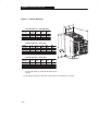
1
spl_en_a.fm5 Page 1 Monday, September 15, 1997 1:31 PM
Allen-Bradley
160 SSC™
Variable
Speed
Controller
(Series A)
Installation
Manual
0.37 – 2.2 kW (1/2 – 3 HP)
FRN 4.01, 4.04, 4.07
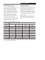
Table of Contents
Index
This manual is intended to guide qualified
personnel in the installation and operation of this
product.
Because of the variety of uses for this equipment
and because of the differences between this
solid-state equipment and electromechanical
equipment, the user of and those responsible for
applying this equipment must satisfy themselves
as to the acceptability of each application and use
of the equipment. In no event will Allen-Bradley
Company be responsible or liable for indirect or
consequential damages resulting from the use or
application of this equipment.
The illustrations shown in this manual are
intended solely to illustrate the text of this
manual. Because of the many variables and
requirements associated with any particular
installation, the Allen-Bradley Company cannot
assume responsibility or liability for actual use
based upon the illustrative uses and applications.
No patent liability is assumed by Allen-Bradley
Company with respect to use of information,
circuits or equipment described in this text.
Reproduction of the content of this manual, in
whole or in part, without written permission of
the Allen-Bradley Company is prohibited.
The information in this manual is organized in
numbered chapters. Read each chapter in
sequence and perform procedures when you are
instructed to do so. Do not proceed to the next
chapter until you have completed all procedures.
Throughout this manual we use notes to make you
aware of safety considerations:
ATTENTION: Identifies information
about practices or circumstances that
can lead to personal injury or death,
property damage or economic loss.
Attentions help you:
D identify a hazard
D avoid the hazard
D recognize the consequences
Important: Identifies information that is
especially important for successful application
and understanding of the product.
$$#
%$ !$ . . . . . . . . . . . . . . . . . . . . . . . . . . . . . . . . . . . . . . . . . . . . . . . . .
!$" "$ "%$ #
DU–1
General Information . . . . . . . . . . . . . . . . . . . . . . . . . . . . . . . . . . . . . . . . . . . . . . . . . . 1–1
Conventions Used In This Manual . . . . . . . . . . . . . . . . . . . . . . . . . . . . . . . . . . . . . . . 1–2
!$" #$$ "
Installation and Storage . . . . . . . . . . . . . . . . . . . . . . . . . . . . . . . . . . . . . . . . . . . . . . . .
EMC Directive 89/336/EEC Compliance . . . . . . . . . . . . . . . . . . . . . . . . . . . . . . . . . .
Controller Features . . . . . . . . . . . . . . . . . . . . . . . . . . . . . . . . . . . . . . . . . . . . . . . . . . .
Controller Operation Without a Program Keypad Module . . . . . . . . . . . . . . . . . . . .
Motor Cable Recommendations . . . . . . . . . . . . . . . . . . . . . . . . . . . . . . . . . . . . . . . . .
Power Wiring For Preset Speed and Analog Signal Follower Models . . . . . . . . . . . .
Control Wiring Requirements . . . . . . . . . . . . . . . . . . . . . . . . . . . . . . . . . . . . . . . . . . .
Control Wiring – Analog Signal Follower Model . . . . . . . . . . . . . . . . . . . . . . . . . . .
Control Wiring – Preset Speed Model . . . . . . . . . . . . . . . . . . . . . . . . . . . . . . . . . . . .
Control Wiring Diagrams . . . . . . . . . . . . . . . . . . . . . . . . . . . . . . . . . . . . . . . . . . . . . .
2–1
2–1
2–2
2–2
2–3
2–4
2–5
2–5
2–5
2–6
!$" " " '! %
Features . . . . . . . . . . . . . . . . . . . . . . . . . . . . . . . . . . . . . . . . . . . . . . . . . . . . . . . . . . . .
Display Mode . . . . . . . . . . . . . . . . . . . . . . . . . . . . . . . . . . . . . . . . . . . . . . . . . . . . . . .
Program Mode . . . . . . . . . . . . . . . . . . . . . . . . . . . . . . . . . . . . . . . . . . . . . . . . . . . . . . .
Removing Program Keypad Module . . . . . . . . . . . . . . . . . . . . . . . . . . . . . . . . . . . . .
3–1
3–1
3–1
3–2
!$" $"$!
Start–up Procedure (Analog Signal Follower Model) . . . . . . . . . . . . . . . . . . . . . . . . 4–1
Start–up Procedure (Preset Speed Model) . . . . . . . . . . . . . . . . . . . . . . . . . . . . . . . . . 4–1
!$" "$"# " "
Overview of Parameters . . . . . . . . . . . . . . . . . . . . . . . . . . . . . . . . . . . . . . . . . . . . . . .
Programming Example . . . . . . . . . . . . . . . . . . . . . . . . . . . . . . . . . . . . . . . . . . . . . . . .
Display Group Parameters . . . . . . . . . . . . . . . . . . . . . . . . . . . . . . . . . . . . . . . . . . . . .
Program Group Parameters . . . . . . . . . . . . . . . . . . . . . . . . . . . . . . . . . . . . . . . . . . . . .
5–1
5–1
5–2
5–4
!$" " %# $ %$ "$ Fault Information . . . . . . . . . . . . . . . . . . . . . . . . . . . . . . . . . . . . . . . . . . . . . . . . . . . . 6–1
Troubleshooting . . . . . . . . . . . . . . . . . . . . . . . . . . . . . . . . . . . . . . . . . . . . . . . . . . . . . 6–3
Block Diagram of Bulletin 160 Analog Signal Follower Model . . . . . . . . . . . . . . . . 6–4
!!& Controller Specifications . . . . . . . . . . . . . . . . . . . . . . . . . . . . . . . . . . . . . . . . . . . . . . A–1
Controller Dimensions . . . . . . . . . . . . . . . . . . . . . . . . . . . . . . . . . . . . . . . . . . . . . . . . A–4
Catalog Numbers For Bulletin 160 Accessories . . . . . . . . . . . . . . . . . . . . . . . . . . . . . A–5
&
Index . . . . . . . . . . . . . . . . . . . . . . . . . . . . . . . . . . . . . . . . . . . . . . . . . . . . . . . . . . . . . . . I–1
i
Bulletin 160 SSCt Controller
For Ratings of 1/2 - 3 HP (0.37 – 2.2kW)
This document revises the Bulletin 160 SSC Controller User
Manual (Publication 160–5.0, February 1996).
Replace pages 2–5, 2–7, and 2–8 of the User Manual with the
information on the following pages.
ATTENTION: Read the following sections carefully
before installing the Bulletin 160 SSC Controller.
DU–1
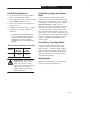
Control Wiring Requirements
D run all signal wiring in either a shielded
cable, or a separate steel conduit.
D only connect shield wire at control
terminal block common terminals 3 and 7.
D do not exceed control wiring length of 15
meters (50 feet).
D use Belden 8760 (or equivalent) – 18AWG
(0.750mm2), twisted pair, shielded or 3
conductor.
À
Control signal cable length is highly dependent on
electrical environment and installation practices. To
improve noise immunity the control terminal block
must be connected to earth ground. Consult
factory for longer control signal cable length applications.
Table 2.DąControl Terminal Block Specifications
Terminal
TB3
Max/Min
Wire Size
mm2 (AWG)
2.5-0.5
(14-22)
Max/Min Wire Torque
Nm. (lb.in.)
0.8-0.4
(8-4)
ATTENTION: The controller is
supplied with an internal 12V
supply. Dry contacts or open
collectors are required for discrete
control inputs. If an external
voltage is applied, component
failure could occur.
ATTENTION: Read the
following sections carefully before
installing the Bulletin 160 SSC.
Control Wiring - Analog Signal Follower
Model
Parameter 59 – [Frequency Source] is used to
select the source of the frequency command.
The frequency source (which controls the
output frequency of the controller) can be
commanded internally using P58 – [Internal
Frequency] or via the Control Terminal Block
(TB3) using a:
D remote potentiometer.
D –10 to +10VDC analog input.
D 4–20mA analog input.
Refer to Chapter 5, parameters 58–60 for
factory default settings.
ATTENTION: Connect and use only
one frequency source at any time. If
more than one frequency source is
connected or in use at the same time,
unintended operation could occur.
If you use P58 – [Internal
Frequency], TB3 – terminal 2 must
be tied to Common (TB3 – terminal 3)
to ensure that unintended operation
does not occur.
Control Wiring - Preset Speed Mode
You can control the output frequency of the
controller via contact closure input to SW1,
SW2, and SW3. A program keypad module is
required to change the factory default settings.
Refer to Chapter 5, parameters 61–70 for the
DU–2
Control Wiring (continued)
Bulletin 160 Analog Signal Follower models (catalog # 160X–XAXXNSFlXX) can be operated using
either a unipolar (frequency control only) or bipolar (frequency and direction control) analog input. Use
Parameter 46 – [Input Mode] to select the control method for start, stop, and direction control. There are
four settings from which to choose (shown in Table 2.E below). For all settings, the controller will reverse
when the voltage on the analog input transitions from positive to negative. In two-wire control (Parameter
46 – settings 1 and 3), negative voltage on the analog input will start the controller, which may be
unintended. This applies to both a negative offset in the analog command, or noise which causes the
analog input to go negative. Refer to Table 2.E below for the recommended installation instructions for
all Parameter 46 settings.
ATTENTION: Read the
following sections carefully before
installing the Bulletin 160 SSC.
Table 2.EąRecommended Wiring Instructions
Parameter 46
Setting
Direction Control
! "
! ! "
! ! "
! ! "
! Analog Signal Follower Model
UniĆpolar Input
BiĆpolar Input
Preset Speed Model
#
#
#
" ATTENTION: When changing the parameter setting for P46 – [Input Mode],
you must cycle power for the change to take effect.
ATTENTION: The program keypad module stop key simulates momentary pushbutton
operation. For “two wire” control schemes (P46 – [Input Mode], setting “1”) the
program keypad module stop button will only provide a “stop” function while the stop
key is depressed.
DU–3
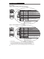
Figure 2.6 - TB3 Three Wire Control (Setting 0)
Figure 2.7a - TB3 Two Wire Run Forward/Run
Reverse" Control (Setting 1)
&&"!) *% $"% !$" %""%,( $ ()* & %")
TB3 Terminal Signal
Reverse
Start
Common
Stop
!" !(
Specification
&&"!) *% ()* & %") $".
!" !(
%$*(%" "%)+( !$&+*À
%$** "%)+( !$&+*À
%##%$Â
%$** "%)+( !$&+* ('+!(
*% %&(* %$*(%""(À
Á
Figure 2.7b - TB3 Two Wire Run Forward"Ã ConĆ
trol (Setting 1)
&&"!) *% $"% !$" %""%,( %") $".
TB3 Terminal Signal
Run Forward
Common
Stop
!" !(
Á
Á
.& %$** "%)+( !$&+*À
Á
%##%$Â
%$** "%)+( !$&+* ('+!(
*% %&(* %$*(%""( À
Ã
Ä
%##%$Â
%$** "%)+( !$&+* ('+!(
*% %&(* %$*(%""(À
Specification
TB3 Terminal Signal
Run Reverse %$** "%)+( !$&+*À
Run Forward %$** "%)+( !$&+*À
Common
Stop
%##%$Â
%$** "%)+( !$&+* ('+!(
*% %&(* %$*(%""( À
Figure 2.8 - TB3 Momentary Run Forward/Run
Reverse" Control (Setting 3)
Specification
&&"!) *% ()* & %") $".
!" !(
%$** "%)+( !$&+*À
Run Forward
%$** "%)+( !$&+*À
Common
Stop
%##%$Â
%$** "%)+( !$&+* ('+!(
*% %&(* %$*(%""(À
-&"$*!%$ % .#%")
À
Á
Â
Common
Stop
&&"!) *% $"% !$" %""%,( %") $".
!" !(
&&"!) *% $"% !$" %""%,( %") $".
TB3 Terminal Signal
Run Reverse
Run Forward %$** "%)+( !$&+*À
Figure 2.7c - TB3 Two Wire Run Forward/Run
Reverse" Ä Control (Setting 1)
Specification
Figure 2.7d - TB3 Two Wire Run Forward/Run
Reverse"Ä Control (Setting 1)
!" !(
TB3 Terminal
Specification
Signal
Run Reverse %$** "%)+( !$&+*À
%#$*(.
%#$*(.
!$*!$
!$*!$
Á
Signal
Specification
TB3 Terminal
Run Reverse %$** "%)+( !$&+*À
Run Forward %$** "%)+( !$&+*À
Common
Stop
%##%$Â
%$** "%)+( !$&+* ('+!(
*% %&(* %$*(%""(À
Internal 12V supply.
If both Run Forward and Run Reverse inputs are closed at the same time an undetermined state could occur.
Do not exceed control wiring length of 15 meters (50 feet). Control signal cable length is highly dependent on electrical
environment and installation practices. To improve noise immunity the control terminal block common must be connected to
earth ground. Consult factory for longer control signal cable length applications.
Upon power up of the controller, FAULT 22 (stop input not present) will occur. To clear the fault, you must cycle the input to the Run Forward
command.
Upon power up of the controller, FAULT 22 (stop input not present) will occur. To clear the fault, you must cycle the input to the Run Forward or
Run Reverse commands.
DU–4
160_5_9DU3.doc
1 Mon Sep 15 11:46:33 1997
Document Update
160 SSC™ Variable Speed
Controller (Series B)
This publication provides new information for the 160 SSC Variable
Speed Controller User Manual, publication 160-5.9, dated
December, 1996. Please place this document in your manual for
future reference.
Important Note
Bulletin 160 SSC Controllers with a catalog number suffix of “S01,”
(i.e. 160S-AA02NS01) will have the “Motor Stall Fault” (F06, page
6-2) detection feature disabled. All other features specified in the
User Manual will be operational.
SSC is a trademark of Rockwell Automation.
Rockwell Automation helps its customers receive a superior return on their investment by bringing
together leading brands in industrial automation, creating a broad spectrum of easy-to-integrate
products. These are supported by local technical resources available worldwide, a global network
of system solutions providers, and the advanced technology resources of Rockwell.
Worldwide representation.
Argentina • Australia • Austria • Bahrain • Belgium • Bolivia • Brazil • Bulgaria • Canada • Chile • China, People’s Republic of • Colombia • Costa Rica • Croatia • Cyprus
Czech Republic • Denmark • Dominican Republic • Ecuador • Egypt • El Salvador • Finland • France • Germany • Ghana • Greece • Guatemala • Honduras • Hong Kong
Hungary • Iceland • India • Indonesia • Iran • Ireland • Israel • Italy • Jamaica • Japan • Jordan • Korea • Kuwait • Lebanon • Macau • Malaysia • Malta • Mexico
Morocco • The Netherlands • New Zealand • Nigeria • Norway • Oman • Pakistan • Panama • Peru • Philippines • Poland • Portugal • Puerto Rico • Qatar • Romania • Russia
Saudi Arabia • Singapore • Slovakia • Slovenia • South Africa, Republic of • Spain • Sweden • Switzerland • Taiwan • Thailand • Trinidad • Tunisia • Turkey • United Arab Emirates
United Kingdom • United States • Uruguay • Venezuela
Rockwell Automation Headquarters, 1201 South Second Street, Milwaukee, WI 53204-2496 USA, Tel: (1) 414 382-2000, Fax: (1) 414 382-4444
Publication 160-5.9DU3 – April, 1997
P/N 40055-188-01 (A)
Copyright 1997 Rockwell International Corporation. All rights reserved. Printed in USA.
160_5_9DU2.doc
1 Mon Sep 15 11:42:00 1997
Document Update
160 SSC™ Variable Speed
Controller (Series B)
This publication provides new and updated material for the 160 SSC
Variable Speed Controller User Manual, publication 160-5.9, dated
December, 1996. Please place this document in your manual for
future reference.
EMC Directive 89/336/EEC
This controller is a component intended for implementation in
machines or systems for the industrial environment. It has been tested
to meet the Council Directive 89/336 Electromagnetic Compatibility
(EMC) and all applicable standards.
Important: The conformity of the controller and filter to any standard
does not guarantee that the entire installation will conform. Many other factors can influence the total installation and only direct measurements can verify total conformity. It is therefore the responsibility of the machine
manufacturer, to ensure, that the conformity is met.
Essential Requirements for a Conforming EMC Installation
1. An input line filter module (see “Accessories” in Appendix A)
must be installed to reduce conducted emissions. When using the
filters listed in Appendix A, the maximum motor cable lengths
must be 75 meters (250 feet) for controllers rated 200-240VAC,
and 40 meters (133 feet) for controllers rated 380-460VAC.
2. The controller system must be mounted in a shielded enclosure
to reduce radiated emissions.
3. Grounding of equipment and cable shields must be solid, with
low impedance connections.
4. Motor and control cables entering the shielded enclosure must
have EMC-tested shielded cable clamps, or grounded metal
conduit.
5. All motor cables must use shielded cable, or be in grounded metal
conduit.
6. All control and signal wiring must use shielded cable or be in
grounded metal conduit.
7. The Common terminals (TB3-3 & 7) must have a solid connection
to PE (protective earth).
SSC is a trademark of Rockwell Automation.
160_5_9DU2.doc
2
2 Mon Sep 15 11:42:00 1997
160 SSC™ Variable Speed Controller (Series B)
General Instructions for an
EMC Compliant Installation
Refer to Figure 1.
Shielded Enclosure
• Typical NEMA or IEC metal enclosures are adequate.
• The ground connection of the shielded enclosure must be solidly
connected to the PE terminal of the controller. Good conductivity
must be assured – grounding must provide a low impedance path
to high frequency signals.
• All wiring, except input power leads, must use shielded cable.
• Input power, output power and control wiring inside the enclosure
must be physically separated.
• Input power, output power and control wiring outside the enclosure
must use separate shielded cables, or separate conduit.
Cable Clamps
• Use suitable EMC-tested cable clamps only.
• The connection area must be 360 degrees around the shielded cable.
• The cable clamps also provide strain-relief for the cable.
• When using conduit, the contact point of metal entry connections
must be free of paint or non-conductive surfaces and solidly
connected with good conductivity to the enclosure.
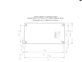
Figure 1 Recommended Grounding Configuration
Enclosure Ground Connection
PE
AC
Input Line
R (L1)
Line
S (L2)
T (L3)
S (L2)
T (L3)
R (L1)
Filter
Ground Tab – PE
Line Power TB1
L1
R
L2
S
L3
T
BR
–
BR
+
FAULT
READY
to TB3
1 2 3 4 5 6 7 8 9 10 11
Control Wiring TB3
Motor Wiring TB2
TI
U
T2
V
T3
W
–
DC
Control
Cabinet *
+
DC
Shielded Motor Cable
W (T3)
V (T2)
U (T1)
Shielded Enclosure
= EMC Tested Shielded Cable Clamp (or Metal Conduit)
* When the control circuitry is located outside of the 160 enclosure.
to Motor
160_5_9DU2.doc
3 Mon Sep 15 11:42:00 1997
160 SSC™ Variable Speed Controller (Series B)
3
Motor Cable
• The cable between the controller and motor must be a 4-wire
shielded cable (three phases and ground). Refer to Figures 2 & 3.
• When using a line filter module as specified in Appendix A, motor
cable lengths shall be limited to 75 meters (250 feet) for controllers
rated 200-240VAC and 40 meters (133 feet) for controllers rated
380-460VAC.
• Inside the shielded enclosure, shielded motor cable must be used
as close to the controller’s output terminals as possible. The shield
must be solidly connected to the PE terminal of the controller.
• Where the shielded motor cable exits the enclosure, an EMC-tested
cable clamp, or metal conduit must be used to solidly connect the
cable shield to the enclosure.
• The shield on the motor side must be solidly connected to the motor
housing with an EMC-tested cable clamp, or conduit, providing
good conductivity from the cable shield to the motor housing.
Figure 2 Motor Connections
Ground Tab – PE
L1
R
L2
S
L3
T
BR
–
BR
+
FAULT
READY
4 Wire
Shielded Motor Cable
1 2 3 4 5 6 7 8 9 10 11
Motor Wiring TB2
TI
U
T2
V
T3
W
–
DC
+
DC
Ground to Motor Housing
W (T3)
V (T2)
U (T1)
Shielded Enclosure
= EMC Tested Shielded Cable Clamp (or Metal Conduit)
* When the control circuitry is located outside of the 160 enclosure.
Figure 3 Shielded Motor and Control Cable Example
Stranded Copper Wire
Plastic Insulation
Inner Plastic Sheath
Compact Screen of Galvanized (Tinned) Copper or Steel
Outer Plastic Jacket
160_5_9DU2.doc
4
4 Mon Sep 15 11:42:00 1997
160 SSC™ Variable Speed Controller (Series B)
Control Cable
• Control wiring must use shielded cable, or grounded metal conduit.
Refer Figures 3 and 4.
• The shield must be connected to signal common at both ends of
the cable.
• The Common terminals (TB3-3 & 7) must be solidly connected
(and as short as possible) to the PE terminal of the controller.
Figure 4 Control Connections
Ground Tab – PE
L1
R
L2
S
L3
T
BR
–
BR
+
FAULT
READY
Control
Cabinet *
1 2 3 4 5 6 7 8 9 10 11
Control Wiring TB3
TI
U
T2
V
T3
W
–
DC
to TB3
+
DC
Signal
Common
Shielded Control
Cable
Shielded Enclosure
= EMC Tested Shielded Cable Clamp (or Metal Conduit)
* When the control circuitry is located outside of the 160 enclosure.
Rockwell Automation helps its customers receive a superior return on their investment by bringing
together leading brands in industrial automation, creating a broad spectrum of easy-to-integrate
products. These are supported by local technical resources available worldwide, a global network
of system solutions providers, and the advanced technology resources of Rockwell.
Worldwide representation.
Argentina • Australia • Austria • Bahrain • Belgium • Bolivia • Brazil • Bulgaria • Canada • Chile • China, People’s Republic of • Colombia • Costa Rica • Croatia • Cyprus
Czech Republic • Denmark • Dominican Republic • Ecuador • Egypt • El Salvador • Finland • France • Germany • Ghana • Greece • Guatemala • Honduras • Hong Kong
Hungary • Iceland • India • Indonesia • Iran • Ireland • Israel • Italy • Jamaica • Japan • Jordan • Korea • Kuwait • Lebanon • Macau • Malaysia • Malta • Mexico
Morocco • The Netherlands • New Zealand • Nigeria • Norway • Oman • Pakistan • Panama • Peru • Philippines • Poland • Portugal • Puerto Rico • Qatar • Romania • Russia
Saudi Arabia • Singapore • Slovakia • Slovenia • South Africa, Republic of • Spain • Sweden • Switzerland • Taiwan • Thailand • Trinidad • Tunisia • Turkey • United Arab Emirates
United Kingdom • United States • Uruguay • Venezuela
Rockwell Automation Headquarters, 1201 South Second Street, Milwaukee, WI 53204-2496 USA, Tel: (1) 414 382-2000, Fax: (1) 414 382-4444
Publication 160-5.9DU2 – May 1997
Copyright 1997 Rockwell International Corporation. All rights reserved. Printed in USA.
It is your responsibility to
thoroughly inspect the equipment before
accepting the shipment from the freight company.
Check the item(s) received against the purchase
order. If any items are obviously damaged, do
not accept delivery until the freight agent notes
the damage on the freight bill.
If you find any concealed damage during
unpacking notify the freight agent. Also, leave
the shipping container intact and have the freight
agent make a visual inspection of the equipment
in order to verify damage.
1
Remove all packing material,
wedges, or braces from within and around the
controller. Remove all packing material from the
heat sink.
After unpacking, check the item(s)
nameplate catalog number against the purchase
order. An explanation of the catalog numbering
system for the Bulletin 160 controller is included
as an aid for nameplate interpretation. Refer to
the following page for complete nomenclature.
IMPORTANT:Before you install and start up the
controller, inspect the mechanical integrity of the
system (e.g., look for loose parts, wires,
connections, etc.).
In addition to the precautions listed throughout
this manual, you must read and understand the
following statements which are general to the
system.
ATTENTION: This controller
contains ESD (Electrostatic
Discharge) sensitive parts and
assemblies. Static control precautions
are required when installing, testing,
servicing or repairing this assembly.
Component damage may result if
ESD control procedures are not
followed. If you are not familiar
with static control procedures,
reference A–B Publication
8000–4.5.2, “Guarding Against
Electrostatic Damage” or any other
applicable ESD protection handbook.
ATTENTION: An incorrectly
applied or installed controller can
result in component damage or
reduction in product life. Wiring or
application errors such as undersizing
the motor, supplying an incorrect or
an inadequate AC supply, or
excessive ambient temperatures may
result in system malfunction.
ATTENTION: Only personnel
familiar with the controller and
associated machinery should plan or
implement the installation, start–up,
and subsequent maintenance of the
system. Failure to comply may result
in personal injury and/or equipment
damage.
1–1
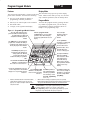
Chapter 1 - Figure 1.1 - Catalog Number Code Explanation
160 - A A04 N SF1
First
Position
Second
Position
Third
Position
Fourth
Position
Bulletin
Number
Voltage Rating
Current
Rating
Enclosure
Type
Motor Rating
Current
Rating HP kW
A02
A03
A04
A08
A12
1/2
3/4
1
2
3
0.37
0.55
0.75
1.50
2.20
CAT
I
N
P
U
T
A01
A02
A03
A04
A06
A08
A12
A 200Ć240V 1∅
200Ć240V 3∅
An S" in the
Bulletin Number
denotes a single
phase input
voltage.
Available up to
motor ratings of
2 HP (1.5KW)
Max.
B 380Ć460V 3∅
2.1A
2.7A
3.6A
6.8A
9.6A
160 – AA04NSF1P1
V: 200-240 3
A: 5.4
Hz: 50/60
VA: 2200
O
U
T
P
U
T
Current
Rating HP
2.0A
2.6A
3.4A
6.5A
9.2A
SER
A01
A02
A03
A04
A06
A
200-230 3
4.5
0-240
Motor
Rating: 0.75kW/1HP
V:
A:
Hz:
ALLEN-BRADLEY
Programmer
(Optional)
Control
Program
Keypad Module
Voltage Rating B
Motor Rating
2.3A
3.0A
3.9A
7.5A
10.6A
Sixth
Position
PS1 = Preset
Speed
Output Current Rating
At Listed Voltages - Rating A
180V 200V 208V 230V 240V
2.3A
3.0A
4.1A
7.8A
11A
Fifth
Position
SF1 = Analog
Letter Type
Signal
N Open (IP20)
Follower
Voltage Rating A
2.3A
3.0A
4.5A
8.0A
12A
P1
ÎÎÎ
1/2
3/4
1
2
3
kW
Output Current Rating
At Listed Voltages - Rating B
342V 380V 400V 415V 460V
0.37
0.55
0.75
1.50
2.20
1.2A
1.7A
2.3A
4.0A
6.0A
1.2A
1.7A
2.2A
4.0A
5.8A
1.2A
1.6A
2.1A
3.9A
5.5A
1.1 A
1.5A
2.0A
3.7A
5.3A
1.0 A
1.4A
1.8A
3.4A
4.8A
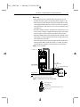
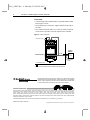
Nameplate Information
Nameplate is located on the
side of the unit.
MADE IN U.S.A.
Conventions Used In This Manual
Parameter numbers and names are shown in bold typeface and follow the format PXX – [*] where P
denotes parameter, XX denotes the two digit parameter number, and * represents the parameter name.
For example, P01 – [Output Frequency].
1–2
!%#
$%% #
$%% % #
Take these actions to prolong controller life and
performance:
D store within an ambient temperature range of
-40_ to +85_C
D store within a relative humidity range of 0%
to 95%, non–condensing
D protect the cooling fan by avoiding dust or
metallic particles
D avoid storing or operating the controller
where it could be exposed to a corrosive
atmosphere
D protect from moisture and direct sunlight
D operate at an ambient temperature range of
0_ to +50_C
To maintain proper working conditions, install
the controller on a flat, vertical and level
surface. Use mounting screws up to 4.5mm
(0.177 inches) in diameter or mount on 35mm
DIN Rail.
#%' !
2
Important: The conformity of this controller and
filter to any standard does not guarantee that the
entire installation will conform. Many factors can
influence the total installation and only direct
measurements can verify total conformity.
A copy of the Declaration of Conformity (DOC) is
available from your local Allen–Bradley sales
office.
&# &% "&#%$
$#!% #' '% "#$',, (.'-#'! , +/,
(.'-#'! (+*.
%#
&&
&
0 -( &
$
#'
% #'
%
))'#0 (+ -#%, (' ('-+(%%+ #&',#(',
' /#!"-,
%
"+ &.,- &#'#&.& ( &&
#'", %+' +(.' %% ,#, ( -" ('-+(%%+ ,
#-"+ +#% (+ &(.'-#'! "(%, À
&%
#$ '# Á
This product complies with Electromagnetic
Compatibility (EMC) Directive 89/336/EEC, when
the following requirements for a conforming
installation are applied:
D an input line filter must be installed to reduce
conducted emissions. Refer to the accessory
list in Appendix A.
D the controller system must be mounted in a
shielded enclosure to reduce radiated
emissions. A typical NEMA or IEC metal
enclosure is adequate.
D motor cables must be in conduit, or have
shielding/armor with equivalent attenuation to
reduce radiated emissions.
D motor cable lengths are as specified in table
2.A.
À
D control and signal wiring must be in conduit or
have shielding with equivalent attenuation.
Á
2–1
Chapter 2 - Figure 2.2 - Controller Features
Ground Tab
L1
R
L2
S
L3
T
BR
-
BR
+
Ready/Fault Indicating
Panel % # !#
&% ! %#!#$
FAULT
LEDs - %
!"#%! $%%&$
READY
1 2 3 4 5 6 7 8 9 10 11
T1
U
T2
V
T3
W
Terminal Block One
(TB1) - !# !'#
-
DC
+
DC
Terminal Block Three (TB3)
- !# ! %#! # Terminal Block Two (TB2)
- !# !%!# # Fan
DIN Latch
Controller Features
Figure 2.2 above details the features of both the
Analog Signal Follower and Preset Speed
models.
Program Keypad Module $ !## $"#%) %! !#
$ %!#) $% !"%! ) * %! % ! % %! &#
# %! "%# #!# )"
!& !# % (" %! !
& %! %)
Diagnostics For Controllers Without a
Program Keypad Module
There are two indicators provided to display
the controller’s status condition.
Note: The features are the same for single and
three phase units.
The READY (green) indicator illuminates
when the DC bus is charged and the
controller is ready to run.
Controller Operation Without a Program
Keypad Module
The FAULT (red) indicator illuminates
when a controller fault condition exists.
Refer to Chapter 6 for details on how to
clear a fault and general troubleshooting
procedures.
Bulletin 160 controllers are fully functional
without the use of a program keypad module.
All control functions can be performed from the
control terminal block (TB3). A program
keypad module is required to change the factory
default parameter settings.
2–2
Chapter 2 - Motor Cable Recommendations
Long Motor Cable Effects
A variety of cable types are acceptable for
variable speed controller installations. For many
installations, unshielded cable is adequate,
provided it can be separated from sensitive
circuits. As an approximate guide, allow a
spacing of 1 meter (3.3 feet) for every 10 meters
(33 feet) of unshielded length. If you cannot
separate motor cables from sensitive circuits, or if
you must run motor cables from multiple
controllers (more than three) in a common
conduit or cable trays, shielded motor cable is
recommended to reduce system noise.
Installations with long motor cables may require
the addition of output reactors to reduce voltage
reflections at the motor, and reduce cable
charging current. Capacitive charging of long
motor cables may draw current in excess of the
controller rating. The output reactor should be
installed between the controller output terminals
and the motor, and mounted near the controller.
The controller should be installed as close to the
motor as possible.
Motor cables should be four–conductor with the
ground lead and shield (if using shielded cable)
connected to the controller ground terminal and
the motor frame ground terminal.
Note: If your application requires motor cable
lengths exceeding the recommendations listed
below, contact your local Allen–Bradley Sales
Office.
Table 2.A Recommended Shielded Motor Cable Lengths
Recommended Max. Cable Length m (ft.)
Controller Type
kW (HP)
Voltage
Economy Motor
(1000V)
Standard Motor
(1200V)
Inverter Rated Motor
(1600V)
2–3
Chapter 2 - Installation/Wiring
Power Wiring For Preset Speed and
Analog Signal Follower Models
Table 2.B
Power Terminal Block Specifications
Terminal Screw
Size
Table 2.C Recommended AC Input Line Fuse
UL Class J, CC, or BS88 (or equivalent)
3∅ Rating
kW (HP)
Max/Min Max/Min
Wire Size
Torque
mm2 (AWG) Nm. (lb.in.)
1∅ Rating
kW (HP)
Fuse
230V Rating
Fuse
460V Rating
À
À
Á
Á
Á
À
Á
Figure 2.3 - Power Wiring For Analog
Signal Follower and Preset Speed Models
Denotes European sizes.
Must be dual element time delay, Gould AJT or equivalent.
If blowing fuses is a problem, use dual element type fuses.
Required Branch
Circuit Disconnect Â
Input Line Fuses - !' Â
Ground Tab
FAULT
READY
Dynamic Brake Module
Option Ã
L1
R
L2
S
L3
T
T1
U
T2
V
T3
W
BR
-
-
DC
The controller is
!%!# Å
intended to be commanded by control input
signals that will start and stop the motor. A
device that routinely disconnects then
reapplies line power to the controller for the
purpose of starting and stopping the motor
should not be used. If it is necessary to use
this method for starting and stopping or if
frequent cycling of power is unavoidable,
make sure that it does not occur more than
once a minute.
Do not connect power factor
correction capacitors to controller output terminals
T1, T2, and T3 (U, V, and W).
2–4
BR
+
Terminal Block One (TB1) - !#
!(# # $$%!#
+
Terminal Block Two (TB2) - !#
!%!# "%!# !&
DC
Capacitor Module
Option Ä
ATTENTION:
ATTENTION:
Â
Ã
For single phase input applications, connect the AC input line
to input terminals (L1) R and (L2) S.
Connection for dynamic brake resistors for all models. must be enabled for proper operation.
See Appendix A for part numbers.
Ä
Connection for an external capacitor module. Provides
extended ride through capability and improved inherent
braking performance. See Appendix A for part number.
Å
Bulletin 160 controllers are
and
listed as motor overload protective devices. An external
overload relay is not required for single motor applications.
"&$ Installation/Wiring
! &$! $ #'$ &%
run all signal wiring in either a shielded
cable, or a separate steel conduit.
only connect shield wire at control terminal
block common terminals 3 and 7
do not exceed control wiring length of 15
meters (50 feet).
use Belden 8760(or equivalent) – 18AWG
(0.750mm 2), twisted pair, shielded or 3
conductor.
Control signal cable length is highly dependent on
electrical environment and installation practices. To
improve noise immunity the control terminal block
must be connected to earth ground.
Consult factory for longer control signal cable length
applications.
! &$! $ ! "&! %
$ )
$ *
)
!$#'
ATTENTION: The controller is
supplied with an internal 12V
supply. Dry contacts or open
collectors are required for discrete
control inputs. If an external
voltage is applied, component
failure could occur.
! &$! $ ! !!($
!
You can control the output frequency of the
controller via the Control Terminal Block (TB3)
using a remote potentiometer, a –10 to +10 VDC
analog input, a 4–20mA analog input, or P58 –
[Internal Frequency]. Note: Only one
frequency source may be connected at a time. If
the frequency reference potentiometer and the
4–20 mA reference are connected at the same
time, an undetermined frequency reference will
result. If the –10 to +10 VDC analog input is not
used, it should be tied to terminal block common
terminal 7 to improve noise immunity. Refer to
Chapter 5, parameters P58–P60 for factory
default settings.
! &$! $ $%& " !
You can control the output frequency of the
controller via contact closure input to SW1,
SW2, and SW3. A program keypad module is
required to change the factory default settings.
Refer to Chapter 5, parameters 61–70 for the
eight preset frequency factory default settings
and switch configurations.
$ $%
Note: Refer to the diagrams on the following
pages for control wiring information.
2–5
Chapter 2 - Installation/Wiring
Control Wiring
Figure 2.4 - TB3 Control Wiring for Analog Signal Follower Model
&
TB3 Terminal
1
2
FAULT
READY
Â
3
4
5
6
7
8
9
10
11
Signal
Specification
+ 10V Pot
Pot Wiper or
+10/-10 VDC Input
Common
4-20mA Input
Reverse
Start
Common
Stop
Normally Closed
Ω #("(#!(& (('
Relay Common
Normally Open
#"(&# & "$)( !$" Ω
#"(&# & "$)( !$" Ω
#"(( #')& "$)( À
#"(( #')& "$)( À
#!!#" Á
#"(( #')& "$)( &%)& (# #$&( #"(&# & À
)'(#!&$&#&!! & + #)($)('
''(* # ( ( ")(* # ( ( #!"(&+ #"((
#!"(&+ #"((
"(" #"((
Figure 2.5 - TB3 Control Wiring for Preset Speed Model
&
TB3 Terminal
FAULT
READY
Â
1
2
3
4
5
6
7
8
9
10
11
Signal
Specification
SW1
SW2
Common
SW3
Reverse
Start
Common
Stop
Normally Closed
Relay Common
Normally Open
#"(( #')& "$)( À
#"(( #')& "$)( À
#!!#" Á
#"(( #')& "$)( À
#"(( #')& "$)( À
#"(( #')& "$)( À
#!!#" Á
#"(( #')& "$)( &%)& (# #$&( #"(&# & À
)'(#!&$&#&!! & + #)($)('
''(* # ( ( ")(* # ( ( #!"(&+ #"((
#!"(&+ #"((
"(" #"((
À
Internal 12V supply.
Á
Do not exceed control wiring length of 15 meters (50 feet). Control signal cable length is highly dependent on
electrical environment and installation practices. To improve noise immunity the control terminal block must be connected to earth ground. Consult factory for longer control signal cable length applications.
Â
This diagram shows three wire" control. Refer to the following page for diagrams of other control wiring methods.
2–6
Chapter 2 - Installation/Wiring
Control Wiring (continued)
Use P46 – [Input Mode] to select the control
method for start, stop, and direction control.
There are four settings from which to choose:
Figure 2.6 - TB3 Three Wire control (Setting 0)
TB3 Terminal
1
2
3
Setting 1 – two wire “run forward/run
4
reverse”control. Note: The “run” inputs must
5
be maintained.
6
Setting 2 – program keypad module control.
7
8
See page 3–1.
9
Setting 3 – momentary “run forward/run
10
reverse” control. Note: The “run” inputs do
11
Setting 0 – three wire control (this is the
factory default setting).
Signal
Specification
Reverse
Start
Common
Stop
À
À
Â
À
not need to be maintained.
ATTENTION: When changing the
parameter setting for P46 – [Input
Mode], you must cycle power for the
change to take effect.
Figure 2.7 - TB3 Two wire Run forward/run reverse
control (Setting 1)
TB3 Terminal
1
2
ATTENTION: The program keypad
3
module stop key simulates momentary
Á
4
pushbutton operation. For “two wire”
5
control schemes (P46 – [Input Mode],
6
7
setting “1”) the program keypad module
8
stop button will only provide a “stop”
9
function while the stop key is depressed.
10
11
Signal
Specification
Run Reverse
Run Forward
Common
Stop
À
À
Â
À
Explanation of Symbols:
Figure 2.8 - TB3 Momentary Run forward/run
reverse" control (Setting 3)
À
Internal 12V supply.
Á
If both Run Forward and Run Reverse inputs are closed
at the same time an undetermined state could occur.
Â
Do not exceed control wiring length of 15 meters (50
feet). Control signal cable length is highly dependent
on electrical environment and installation practices.
To improve noise immunity the control terminal block
must be connected to earth ground.
Consult factory for longer control signal cable length
applications.
Á
TB3 Terminal Signal
1
2
3
4
5
Run Reverse
6
Run Forward
7
Common
8
Stop
9
10
11
Specification
À
À
Â
À
2–7
2–8
3
The program keypad module is located on the front The controller always powers up in the display
panel of the controller. It features the following: mode. While in this mode you may view all read
only controller parameters, but not modify them.
D five keys on the module for display or
programming controller parameters
D three keys for control inputs to the controller
D directional LEDs
D a 6 digit, seven segment LED display
You enter the program mode by pressing the ESC
key. While in program mode, you can edit any
programmable controller parameters. Refer to
Chapter 5 for programming steps.
& '*# '& &$ + ' ')
$%!'% "(!% #% #' &$ + "
$%#%! $%!'%& * %
&"' & '%#(#(' '&
!"( " ' program mode
indicator && +#( " ' '
$%!'% ) ( " " &$ +
!# ' $%#%! "'#% #& "#'
&$ +
& ' up/down
%%#* +& '# &%# '%#(
&' # $%!'%& #%
"%& " %&
$%!'% ) (& %&&
" # '% + '#
"%& &%# " &$
SELect + & #" + (& * "
$%#%! !# ' " & ' '" #
$%!'% ) ( " +#( $%&&
'& + ' $%#%! !# "'#%
&&
ESCape + #*& +#( '#
'# '*" ' &$ + !#
" $%#%! !# " "
$%#%! !# '& + &#
& & ' '" # $%!'%
) (
%&&" ' enter +
* " $%#%!!"
!# (&& ' (%%"'
) ( &$ + '# "'% "'# !!#%+
" +#( $%&& '& +
' $%#%! !# "'#%
%!"& #" (' &'#$&
&"
counter clockwise LED
(!"'& #"&'"' + *" '
!#'#% %#''& " %)%& %'#" À
%&&" ' reverse + (&& '
!#'#% '# %!$ #*" '# , " '"
%!$ ($ '# '& &' &$ " ' #$$#&'
%'#" Á
À
& #(% '&
&$ + ' $%!'%
) ( #% ( ' #
"(!%
clockwise LED
(!"'& #"&'"' + *"
' !#'#% %#''& " #%*%
%'#" À
! ! $ ! # "$ Á
start + "''& &'%' #!!" *" '
#"'%# % & $%#%!!
#% # &'%'&'#$ #"'%#
*" & &' '# -
stop + "''& '
!#'#% '# -#&' -!$ #%
- % '# &'#$ $".
" #" ' &''" # ! $ ! ! $
! # %
# ! $%#%! +$ !#( + &!( '&
!#!"'%+ $(&(''#" #$%'#" #% -'*# *% #"'%# &!&
&''" - ' $%#%! +$ !#( &'#$ + *
#" + $%#) -&'#$ ("'#" * ' &'#$ + & $%&&
ATTENTION:
3–1
$" & "" ' %
ATTENTION: Ensure that you
disconnect line power and wait
one minute before installing or
removing the program keypad
module. Failure to do so may
result in personal injury or death.
%" & "" ' %
! " !
ATTENTION: This controller
contains ESD (Electrostatic
Discharge) sensitive parts and
assemblies. Static control precautions
are required when installing, testing,
servicing or repairing this assembly.
Component damage may result if
ESD control procedures are not
followed. If you are not familiar
with static control procedures,
reference A–B publication
8000–4.5.2, “Guarding Against
Electrostatic Damage” or any other
applicable ESD protection handbook.
"" ' %
! #
"!%' #
! " $ " # "!%'
! # "!%' " !
" #$ %$#
#$ "" ' %
" "
" ! ! 3–2
$+/!-
/-/+
)"04&2 02/6*%&3 " $/-02&)&.3*6& %&3$2*04*/. /'
",, $/.42/,,&2 0"2"-&4&23 &6*&7 4)& '"$4/29 %&'"5,4
3&44*.(3 ' 9/52 $/.42/,,&2 *3 &15*00&% 7*4) " 2/;
(2"- &90"% /%5,& 4)&3& 0"2"-&4&23 $". #&
$)".(&% 4/ -&&4 9/52 30&$*'*$ "00,*$"4*/. 2&15*2&;
-&.43 . &8"-0,& /' )/7 4/ 02/(2"- " 0"2"-&4&2
*3 3)/7. "4 4)& #&(*..*.( /' )"04&2 /-/ !-!
4
*((*)'4 $)#! -(!/!-.
-(!/!!' %(! !!' %(! 3%(0( -!,0!)4
/*+ * ! !'!/
.! -!,0!)4
.! *'/#!
*/*- 1!-'* 0--!)/
)+0/ * !
0/+0/ *)"%#0-!
-!.!/ -!,0!)4 !/ /*
%&3*2&% "$$&, 4*-&
%&3*2&% %&$&, 4*-&
-"8*-5- '2&15&.$9 2&15*2&%
%&3*2&% 34/00*.( -/%&
-/4/23 2"4&% ."-&0,"4& '2&15&.$9
-/4/23 2"4&% ."-&0,"4& 6/,4"(&
-/4/2 ."-&0,"4& 5,, /"% -03 !
%&3*2&% $/.42/, -&4)/%
%&3*2&% /54054 '5.$4*/.",*49
%&3*2&% 02&3&4 '2&15&.$*&3
ATTENTION: /7&2 -534 #& "00,*&% 4/ 4)& $/.42/,,&2 4/ 0&2'/2- 4)& '/,,/7*.( 34"24;50 02/$&%52& /-& /'
4)& 6/,4"(&3 02&3&.4 "2& "4 *.$/-*.( ,*.& 0/4&.4*", / "6/*% &,&$42*$ 3)/$+ )":"2% /2 %"-"(& 4/ &15*0-&.4 /.,9
3)/5,% 0&2'/2- 4)& '/,,/7*.( 02/$&%52& )/2/5(),9 2&"% ".% 5.%&234".% 4)&
02/$&%52& #&'/2& #&(*..*.( ' ". &6&.4 %/&3 ./4 /$$52 7)*,& 0&2'/2-*.( 4)*3 02/$&%52& * */ -*!! !(*1! *2!- #9 /0&.*.( 4)& #2".$) $*2$5*4 %*3$/..&$4 %&6*$& ".% $/22&$4 4)& -",'5.$4*/. #&'/2& $/.4*.5*.(
/-/+ $!&'%./
&2*'9 4)& $/.42/,,&2 *3 *.34",,&% 0&2 *.3425$4*/.3 /54,*.&% *. )"04&2 *.$,5%*.(
D
D
D
*.*-5- $,&"2".$& %*34".$& #&47&&. $/.42/,,&2 ".% /4)&2 &15*0-&.4
2/0&2 (2/5.%*.( 02"$4*$&3 )"6& #&&. '/,,/7&%
2/0&2 0/7&2 ".% $/.42/, 7*2*.( )"3 #&&. 53&%
&2*'9 4)"4 ,*.& 0/7&2 "4 4)&
%*3$/..&$4 %&6*$& *3 7*4)*. 4)& 2"4&%
6",5& /' 4)& $/.42/,,&2
*3$/..&$4 ".% ,/$+ /54 ",, *.$/-*.( 0/7&2 4/
4)& $/.42/,,&2 *.$,5%*.( *.$/-*.( 0/7&2 4/
4&2-*.",3 ".% ".% /' 0/7&2
4&2-*.", #,/$+ ATTENTION: 53
6/,4"(& -"9 #& 02&3&.4 "4 4)&
0/7&2 4&2-*.", #,/$+3 ".% '/2 "002/8*-"4&,9
/.& -*.54& "'4&2 0/7&2 *3
2&-/6&% '2/- 4)& $/.42/,,&2
&2*'9 4)"4 4)& -/4/2 ,&"%3 "2& $/..&$4&% 4/ 4)&
0/7&2 4&2-*.", #,/$+ 4&2-*.",3 &2*'9 4)"4 4)& *.054 *3 02&3&.4
"4 4)& $/.42/, 4&2-*.", #,/$+
/.'*2- 4)"4 ",, /4)&2 $/.42/, *.0543 "2& $/..&$4&% 4/
4)& $/22&$4 4&2-*.",3 ".% "2& 3&$52& 4–1
!%# Start-Up
$ 6,2 &3# )+( "'0-)6 -+#)
#!,++#!1 1&# -,4#/ 1, 1&#
!,+1/,))#/
$ 6,2 &3# -/,%/* (#6-" *,"2)#
&%!&% #"&' 4')) "'0-)6 $ 1&#
!,+1/,))#/ &0 ##+ -/#3',20)6 -,4#/#" 2- "'$$#/#+1 -/*#1#/ +2* #/ *6 "'0-)6
% , #+ )# 1&# 01/1 +" /#3#/0# (#60
$/,* 1&# -/,%/* (#6-" *,"2)# 0#1 !&% 1, 8 +" !6!)# -,4#/ #$#/
1, 1&# -/,%/**'+% #5*-)# '+ &-1#/ &# %/##+ '+"'!1,/
4')) '))2*'+1# 0# /#*,1#
'+-210 1, !,+1/,) 1#/*'+)
),!( 1, ,-#/1# 1&# !,+1/,))#/
, 6,2 &3# +),% '%+)
,)),4#/ !,+1/,))#/ ,/ /#0#1 -##"
!,+1/,))#/
+),% '%+) ,)),4#/ !,+1/,))#/
&#!( $,/ -/,-#/ *,1,/ /,11',+ 6 0#11'+% 1&# $/#.2#+!6
0,2/!# 1, '10 *'+'*2* 0#11'+%
$ 6,2 /# 20'+% -/,%/* (#6-" *,"2)# 3#/'$6 1&1 1&#
'0 '))2*'+1#" $ 6,2 /# 20'+% )+(
"'0-)6 -+#) 3#/'$6 1&1 1&# '+-21 1, '0 '+
1&# -,0'1',+
002# !,**+" $/,* #'1&#/ 1&# -/,%/* (#6-"
*,"2)# ,/ !,+1/,) 1#/*'+) ),!(
/#0#1 -##" !,+1/,))#/
&#!( $,/ -/,-#/ *,1,/ /,11',+ 6 0#)#!1'+% #$% #"&' &'0 /#.2'/#0 /#*,3'+% )) '+-210
1, +" ,+ 0## '%2/# '+
&-1#/ &# $!1,/6 "#$2)1 0#11'+% $,/ #$%
#"&' '0 7
$ 6,2 /# 20'+% -/,%/* (#6-" *,"2)# 3#/'$6 1&1 1&#
'0 '))2*'+1#" $ 6,2 /# 20'+% )+(
"'0-)6 -+#) 3#/'$6 1&1 1&# '+-21 1, '0 '+
1&# -,0'1',+
),4)6 '+!/#0# 1&# 0-##" 2+1') 1&# *,1,/ #%'+0 1, 12/+
&#!( 1&# "'/#!1',+ ,$ 1&# *,1,/
002# !,**+" $/,* #'1&#/ 1&# -/,%/*
(#6-" *,"2)# ,/ !,+1/,) 1#/*'+) ),!( &#!( 1&#
"'/#!1',+ ,$ *,1,/ /,11',+
002# !,**+" $/,* #'1&#/ 1&# -/,%/*
(#6-" *,"2)# ,/ !,+1/,) ),!( 1#/*'+)
002# !,**+" $/,* #'1&#/ 1&# -/,%/*
(#6-" *,"2)# ,/ !,+1/,) ),!( 1#/*'+)
1/12- '0 !,*-)#1#
#0
0 1&# "'/#!1',+ ,$ *,1,/
/,11',+ !,//#!1
,
'0!,++#!1 +" ),!( ,21 )) '+!,*'+% -,4#/ 1, 1#/*'+)0 +" +" ATTENTION: 20 3,)1%# *6 # -/#0#+1 1 1&#
-,4#/ 1#/*'+) ),!(0 +" $,/ --/,5'*1#)6
,+# *'+21# $1#/ -,4#/ '0 /#*,3#" $/,* 1&# !,+1/,))#/
4'1!& +6 14, ,$ 1&# 1&/## *,1,/ )#"0 !,++#!1#" 1, 1#/*'+)0 +" +" 4–2
$'%
%!'%& " %#%!!"
5
)%)* # %!'%&
This chapter covers both display and program parameters. Display parameters are read only (they
cannot be programmed), while program parameters can be changed to fit your motor control
requirements. You must have a Program Keypad Module to view/change display and program
parameters. The table below describes which parameters apply to the Preset Speed and Analog Signal
Follower models. Refer to the programming example below for programming instructions.
%!'% (!%&
%!'% ,$
2'0-3&' 2'0-3&' 2'0-3&' 2'0-3&' ,# 2'0-3&' ÉÉ
'$ %-**-5(,& . &$1 "-,2 (, #$1"0(.2(-,1 -% !-2' #(1.* 7 ,# .0-&0 +
. 0 +$2$01 ,7 . 0 +$2$0 #$1"0(.2(-, 2' 2 (1 1' #$# .$02 (,1 -,*7
2- 2'$ 0$1$2 .$$# -0 , *-& (&, * -**-5$0 +-#$* $%$0 2- 2'$
*$&$,# 2- 2'$ 0(&'2
%#%!!" +!$ '$ %-**-5(,& (1 , $6 +.*$ -% 2'$ .0-&0 ++(,& 12$.1 0$/3(0$# 2- "' ,&$ . 0 +$2$0 1$22(,& , 2'(1 $6 +.*$
. 0 +$2$0 ! (1 "' ,&$# %0-+ (21 % "2-07 #$% 3*2 1$22(,& -% 1$"-,#1 2- 1$"-,#1 $%$0 2- ' .2$0 . &$
%-0 , $6.* , 2(-, -% 0-&0 + $7. # -#3*$ #(1.* 7 ,# .0-&0 ++(,& )$71 #' - 0$1$2 4 *3$1 2- -0(&(, *
% "2-07 #$% 3*2 1$22(,&1 0$%$0 2- &' ( '&
'#"
&%$'#"
- .0-&0 + 2'$ 4 *3$ -% . 0 +$2$0 $,2$0 2'$ .0-&0 +
&0-3. !7 .0$11(,& 2'$ .$ )$7 '$ 8.0-&0 + +-#$ (,#(" 2-0 5(**
(**3+(, 2$
,$ &$ ,
0-&0 + -#$ ,#(" 2-0
0$11 3.#-5, )$71 3,2(* 2'$ #$1(0$# . 0 +$2$0 #(1.* 71 , 2'(1 " 1$
0$11 2'$ $"2 )$7 '$ .0-&0 + +-#$ (,#(" 2-0 %* 1'$1 (,#(" 2(,&
.0$11 2'$ 3. )$7 3,2(* . 0 +$2$0 ! #(1.* 71
2' 2 7-3 " , 31$ 2'$ 3.#-5, )$71 2- "' ,&$ 2'$ . 0 +$2$0 4 *3$
' ,&$ 2'$ #$"$* 2(+$ 4 *3$ %0-+ 2'$ % "2-07 #$% 3*2 -% 1$"-,#1 2 1$"-,#1 !7 .0$11(,& 2'$ #-5, )$7 3,2(* #(1.* 71
#' -,2(,3-31*7 '-*#(,& 2'$ 3. -0 #-5, )$7 5(** " 31$ 2'$ 4 *3$ 2-
(,"0$ 1$ -0 #$"0$ 1$ 1 *-,& 1 2'$ )$7 (1 .0$11$#
'$, 2'$ #$1(0$# 4 *3$ #(1.* 71 .0$11 2'$ )$7 '(1 50(2$1
2'$ ,$5 4 *3$ 2- +$+-07 '$ .0-&0 + +-#$ (,#(" 2-0 5(** 12-.
%* 1'(,& ,# 2'$ #(1.* 7 5(** %* 1' -,"$ (,#(" 2(,& 2' 2 2'$ ,$5 4 *3$
' 1 !$$, ""$.2$#
#' % 2 ,7 2(+$ 5'(*$ (, 2'$ .0-&0 + +-#$ 7-3 5(1' 2- !-02 2'$
$#(2(,& .0-"$11 .0$11 2'$ .$ )$7 '$ -0(&(, * 4 *3$ -% 2'$ . 0 +$2$0
5(** 0$+ (, 3,"' ,&$# ,# 7-3 5(** !$ $6(2$# %0-+ 2'$ .0-&0 + +-#$
0-&0 + -#$ ,#(" 2-0 * 1'$1
0-&0 + -#$ ,#(" 2-0
2-.1 * 1'(,&
0-&0 + -#$ ,#(" 2-0
2-.1 * 1'(,&
5–1
$(& '$ , &#)$ &!(&'
This group of parameters consists of commonly viewed controller operating conditions such as controller
output frequency, output voltage, output current and frequency command. All parameters in this group
are read only.
Display Group
"39 1%= *-2( -8 2)')77%6= *36 8,) '3286300)6 83 (-740%= % 74)'-*-' 4%6%1)8)6 )%', 8-1) -8 -7 43;)6)( 94 ,-7 -7
)74)'-%00= 97)*90 ;,)2 8639&0)7,338-2+ %2( 1%/-2+ 7=78)1 %(.9781)287 3003; 8,)7) 78)47 83 1%/) 8,) '3286300)6
43;)6 94 %8 % 74)'-*-' 4%6%1)8)6
!,-0) -2 (-740%= 13() -2'6)1)28 83 8,) 4%6%1)8)6 =39 ;-7, 83 7)) ;,)2 8,) '3286300)6 43;)67 94
6)77 8,)
/)= 8;-') !,)2 =39 '='0) 43;)6 83 8,) '3286300)6 -8 ;-00 (-740%= 8,) 4%6%1)8)6 8,%8 =39 7)8
#( * =39 ',%2+) %2= 4%6%1)8)67 8,) '3286300)6 ;,)2 43;)6)( 94 ;-00 7,3; 8,) 0%78 4%6%1)8)6 8,%8 ;%7 46)7)28 &)*36) =39 ;)28 -283 13()
Parameter Description
P#
01
)($)( &%)",-740%=7 8,) 398498 *6)59)2'= %8 8)61-2%07
%2( 02
04
%2( !
)($)( #*&-740%=7 8,) 398498 43;)6 46)7)28 %8 8)61-2%07 %2( 83 >
>
83 #%< 308%+)$
308
83 -1)7
3286300)6 %8)(
98498 966)28
147
83 -1)7 %8)(
3286300)6 98498
3;)6
/!
83 #
$
83 # $
308
83 >
83 91)6-' %09)
83 )+6)) 83 -2%6= 91&)6
%2( !
)($)( )&&"(-740%=7 8,) 398498 '966)28 46)7)28 %8 8)61-2%07
%2( "('
%2( !
)($)( # (-740%=7 8,) 398498 :308%+) 46)7)28 %8 8)61-2%07
%2( 03
"+
"
%2( !
05
)' # (
06
&%)", #!!" -740%=7 8,) *6)59)2'= 8,%8 8,) '3286300)6
-740%=7 8,) 97 308%+) 0):)0
-7 '311%2()( 83 398498 ,-7 '311%2( 1%= '31) *631 %2= 3* 8,) *6)59)2'=
7396')7 7)0)'8)( &= &%)", ( 36 *631 % '966)280= 7)0)'8)( 46)7)8
*6)59)2'=
07
'( ) ( -740%=7 8,) '3()( 0%78 *%908 291&)6
* % *%908 -7 '966)280=
%'8-:) ,%7 238 &))2 '0)%6)( 8,) (-740%= ;-00 *0%7, )) ,%48)6 *36 *%908 '3()
()7'6-48-327
08
('" !$&()&-740%=7 8,) 8)14)6%896) 3* 8,) '3286300)6
,)%87-2/
09
#"(&# & (()'-740%=7 8,) 78%897 3* 8,) '3286300)6 -2 % &-2%6=
'3()( *361%8
#( ? -2%'8-:)
%2( % ? %'8-:)
5–2
-8 -8 -8 -8 922-2+
36;%6(
'')0
)')0
Display Group
Parameter Description
P#
10
11
$' - !!#&!- ! '&* %&'$##!
'%!-' *&'$# $ $#(&$!!& &"+& ' -
#
)"& !)
)"& !)
, !)
)"& !)
($ #&- )"&
($ &'
!!#&!- ! '&* %&'$##!
12
! !'%!-' ( $%# # !$' '(( $ ( %&!!!
#%)(' # #&- $ $&"(
( ( ( ( *&'
($%
(&(
$( '
13
" '%!-' ( #! # !(&! &'
ÁÁÁ
ÁÁÁ
ÁÁÁ
(+# "$($& *$!( # "$($& )&&#(
14
$ $' - !!#&!- ! '&*
%&'$##!
15
!'%!-' ( $%# # !$' '(( $ &"#!
!$ & #%)(' # # #&- $ $&"( '
%&"(& %%!' ($ ( &'( % "$! $#!-
( ( ( ÁÁÁÁÁ
ÁÁÁÁÁ
ÁÁÁÁÁ
ÁÁÁÁÁ
ÁÁÁÁÁ
ÁÁÁÁÁ
)"& !)
)"& !)
($ #&- )"&
( $( '
5–3
&*( Parameters and Programming
(%(# (%+& (#*()
This group contains parameters whose values can be programmed. Refer to the “Programming Example”
outlined earlier in this chapter. Unless otherwise stated, parameters that are programmed while the
controller is running take immediate effect.
Program Group
P#
30
Parameter Description
" !# !% '* ,
!$$
$!*)
*%(.
+"*
,' '&+
'&+
,' '&+
'&+
,' 2
2
,' 2
2
,' -%*!
$-
,' 2
2 Á
,' '*
-&!,+ &
,' '*
-&!,+
'$,
'$,+ '*
-&!,+
& '*
-&!,+
'&,*'$$* ,' *%( *'% 2 ,' -!#+# ('+$. *, !+ $!&* '* &1 !&*+ !& '%%&
*)-&1 -&$++ +(, !+ +, ,' .$- ', * , & 3
0 *)-&1 '
&
a $ '
31
" !# !% '* ,
!%
!#
a $ '
!%
'&,*'$$* ,' *%( *'% -!#+#
('+$. ,' 2 *, !+ $!&* '* &1 *+ !& '%%& *)-&1
-&$++ +(, !+ +, ,' .$- ', * , & 3 " !#
!-* '.
32À !$!#+# ('+$.'/+, *)-&1 ,
, '&,*'$$* /!$$ '-,(-,
'&,!&-'-+$1
%* !+ (*%,* &&', (*'*%% / !$ , '&,*'$$* !+ *-&&!&
33À -!#+# ('+$.!
+, *)-&1 , '&,*'$$* /!$$ '-,(-,
%* !+ (*%,* &&', (*'*%% / !$ , '&,*'$$* !+ *-&&!&
34
*%& % "*,*%!&+ +,'((!& %' -+ 1 ,
'&,*'$$*
/ & +,'( !+ !&!,!, * ,' , %" !# & %"
%"*) !*%+ **!$) %( ,' ,'(
'+, ,' ,'(
&",!'& *#!&
35
36
) ('+$., .$- ,' %','*+ *, &%($, *)-&1
) %"*, .$- ,' %','*+ *, &%($, .'$,
À
The analog inputs to the controller (i.e.,4-20mA, 0 to +10 V, or remote potentiometer) can be scaled to P32 - [Minimum Frequency] and
P33 - [Maximum Frequency] by programming P60 - [Analog Scale Teach].
Á
For controllers without a program keypad module, you can change P35 - [Base Frequency] to 50 Hz via a dipswitch located under the blank
front panel. See the Removing Program Keypad Module section in Chapter 3.
5–4
Chapter 5 - Program Groups
P#
Parameter Description
37
[Maximum Voltage]-, -! !"
38
[Boost Select]-, -! ((,- /(%-
Min/Max
Range
Units
Factory
Default
(%-
(%-, (+
.'"-,
' (+
.'"-,
-( .&+"
%.
-( 2
2
-( 2
2
-( (+
.'"-, '
(.-).-
-( (+
.'"-,
P37 - [Maximum Voltage] &.,- +-+ -!' (+ *.% -( P36 - [Base Voltage]
!,- /(%- -!- -! ('-+(%%+ 0"%%
' +"', -! (%-, )+ 2 .+/
[Base Voltage], %
100
,
(%-,
50
,
+*
y
--"' , -!+(. ! %(0
b
0
Setting
39
50
100
[Base Frequency], %
Boost Voltage % of [Base Voltage]
Setting Fan/Pump Curves À
À [Skip Frequency](+$, "' ('#.'-"(' 0"-! P40 - [Skip Frequency
Band] +-"' +' ( +*.'", - 0!"! -! ('-+(%%+ 0"%% ()+-
('-"'.(.,%1
Frequency
Controller Output
(&&' ' a Frequency
+*.'1
$")
+*.'1
--"'
y 0( -"&,
P40-[Skip Freq Band
b --"'
'
Time
40
[Skip Frequency Band]-+&"', -! ' +(.' -! P39 - [Skip
Frequency] )+&-+ ! -.% ' 0"-! 0"%% -"&, [Skip Frequency
Band -! ' (/ ' -! ' %(0 /%. ( 2+( 0"%% ",%
-! ,$") +*.'1
5–5
%(& Program Group
P#
41
Parameter Description
$($& *&!$ !(!'!.- .$!
#+
#
#('
($&,
)!(
.* /(!,%
'/!
.* (+!,!-
*"
*).,*''!,
.%)#
.* .* !*)
!*) -
.* *'.
*'.-
!,.%)# ".*, "*, .$! .
*" *&!$ )&&#( !..%)#
42
$ &(#
*" *&!$ )&&#( !..%)#
*" *&!$ )&&#( !..%)#
*0!,'* "/).%*).
# &(#
-! +!!
-! +!!
+ &(#
((#'
* !,.%)#
%)%(/( !,.%)#
2%(/( !,.%)#
-! +!!
$($& *&!$ )&&#( !. .* (*.*, )(!+'.! "/'' '*
(+-
43
)&&#( "(2%(/( */.+/. /,,!). ''*1!
!"*,! /,,!). '%(%.%)#
*/,- '/! -!. %) +!,!). *" *).,*''!, ,.! */.+/. /,,!).
44
$! "%(! .$. $! $!(' 0*'.#! 1%'' ! ++'%!
.* .$! (*.*, 1$!) ($% $ !( %- -!. .* !%.$!, 3 ,&! *,
3(+ (* !
45
$! $!( *'.#! '!0!' ++'%!
.* .$! (*.*, /,%)# ,&%)#
1$!) ($% $ !( %- -!. .* !%.$!, 3 ,&! *, 3(+ (* !
"% $
& $
$!(
$!(' # %
$!(
$! "
+!!
$!(' # %
$! "
+!!
$! $!(
$! $!(
.*+ *(()
5–6
"
.*+ *(()
"
!(+) Parameters and Programming
Program Group
P#
Parameter Description
46
&(,+ '-,%(&30$1 2'$ "-,20-* (,.321 %-0 $(2'$0 9
5(0$ -0 9 5(0$
03,%5#03,0$4 "-,20-* *1- $, !*$1#(1 !*$1 2'$ .0-&0 + )$7. # +-#3*$ (,.32
"-,20-* '+
'(1 . 0 +$2$0 " ,,-2 !$ .0-&0 ++$# 5'(*$ 2'$ "-,20-**$0 (1
03,,(,& $*' ('-) %,*+ /$ ') +! !& +' +# +
++"& *
47
&"+*
+')/
,$+
2- 3+$0("
*3$
2- 3+$0("
*3$
2- 3+$0("
*3$
9
5(0$ "-,20-*
9 5(0$ "-,20-*
0-&0 + $7. # -#3*$ "-,20-*
-+$,2 07 3, -05 0# 3, $4$01$ -,20-*
,+(,+ '&" ,)-,%(&30$1 2'$ 0$*
++"& *
48
"&.
& 7 -32.32 %3,"2(-, *(27
,+(,+ !& * *++ -!&
0 = Controller
Ready/Faulted
$,$0&(8$# ,# 0$230,1 2- 1'$*% 12 2$ 5'$,
.-5$0 (1 0$+-4$# -0 5'$, % 3*2 -""301
1 = At Frequency
2'$ "-,20-**$0 0$ "'$1 "-++ ,#$# %0$/3$,"7
2 = Controller Running
2'$ "-,20-**$0 (1 03,,(,&
3 = Reverse
2'$ "-,20-**$0 (1 "-++ ,#$# 2- 03, (, 2'$ 0$4$01$
#(0$"2(-,
4 = Motor Overload
5'$, +-2-0 -4$0*- # "-,#(2(-, $6(121
5 = Ramp Regulated
2'$ 0 +. 0$&3* 2-0 (1 +-#(%7(,& 2'$
.0-&0 ++$# ""$*#$"$* 2(+$1 2- 4-(# ,
-4$0"300$,2 -0 -4$04-*2 &$ % 3*2 %0-+ -""300(,&
6 = Above Frequency
2'$ "-,20-**$0 $6"$$#1 2'$ %0$/3$,"7 4 *3$
1$2 (, ,+(,+ !)*!'$
7= Above Current
2'$ "-,20-**$0 $6"$$#1 2'$ 4 *3$ 1$2 (, ,+(,+ !)*!'$ '+
*3$ %-0 ,+(,+ !)*!'$ +312 !$ $,2$0$# (, -%
"-,20-**$0 0 2$# -32.32 "300$,2
8 = Above DC Bus
Voltage
2'$ "-,20-**$0 $6"$$#1 2'$ !31 4-*2 &$ 4 *3$ 1$2
(, ,+(,+ !)*!'$
9 = Retries Exhausted
2'$ ,3+!$0 -% 0$20($1 %-0 *+)+ )"* (1
$6"$$#$#
,+(,+ !)*!'$$2$0+(,$1 2'$ -,-%% .-(,2 %-0 2'$ -32.32 0$* 7 5'$, ,+(,+ '&" ,) (1 1$2 2- ,# ++"& *
& *
2- 8
2- 2- -*21
5–7
!%# Program Group
P#
49
Parameter Description
(
%$
% #)
&%
2.0 to 8.0
0.1kHz
4.0 kHz
0 to 9
Numeric
Value
0
0.5 to 300
0.1 Seconds
10.0
Seconds
0 to 1
Numeric
Value
0
Numeric
Value
0
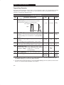
#"&)Carrier frequency for the PWM output waveform.
% Output Current (A)
The chart below provides derating guidelines based on the PWM freq. setting.
100
98
96
94
92
90
88
86
84
1
2
6
5
4
Carrier Frequency, kHz
3
7
8
%: Ignoring derating guidelines can cause reduced controller performance.
50
$%#% #$Maximum number of times the controller will attempt to
reset a fault.
51
$%#% Time between restart attempts.
52
Enables/disables dynamic braking. 0 = Disable, 1 = Enable
% This parameter cannot be programmed while the controller is running.
53
&#'Enables a fixed shape S-Curve.
See formula below:
#&
S-Curve Time Accel or Decel Time x S-Curve" setting (in percent) À
1/2 SĆCurve
Time
1/2 SĆCurve
Time
'
'
a
'
a
S-Curve Time = 10 x .3
'
a
(!
Accel Time = 10 seconds
S-Curve Setting = 3
= 3 Seconds
a
S-Curve
Setting
0 = 0%
1 = 10%
2 = 20%
3 = 30%
4 = 40%
% Maximum
S-Curve time is 60
seconds.
$
5 = 50%
6 = 60%
7 = 70%
8 = 80%
9 = 90%
10 = 100%
'
a
Accel Time
5–8
'
a
Decel Time
À
#*. , Parameters and Programming
Program Group
P#
54
$(1
("
($.-
.),2
!/&.
)$ *"'
!*
*"' !*
*"'
!*
*"'
!*
)$ *"'
!*
)$ *"'
!*
Parameter Description
& , /&.))# )( %'")' )$ 0 %'$'"( *!) '()
#
) *!) '() *#)$# ( $"%!) ) +!* ( *)$")!!. () )$ 0
). ( %'")' ##$) %'$'"" ,! ) $#)'$!!' ( '*###
55
'),2 ,) , --( . !!#'!. ! ('+
%'($##!
56
- . !/&.-!! %'")'( # )' (($) )$'. *!)( '
'() ,# () )$ +!* $ 0 # ) *!) *#)$# ( $"%!) )(
%'")' ,!! () )(! )$ 0 ( %'")' ##$) %'$'""
,! ) $#)'$!!' ( '*### ). ( *,)",' /&. 0$&& )/,
( '/-. & , 2 2&$(" .# $(*/. .) .# )(.,)&& ,
). (*/. ) & . )$'. *!)( )$ 0 ,' $#)'$! *(#
.% $#)'$! # %'")' ())# )$ 0 )$ '# %'$'" .%
$#)'$!
57
,)",' )%# () )$ 0 )( %'")' %'$))( !! $#)'$!!'
%'")'( '$" # # . *#*)$'/ %'($##!
Program Group – Analog Signal Follower Model Only
ÉÉÉ
ÉÉÉ
ÉÉÉ
ÉÉÉ
ÉÉÉ
ÉÉÉ
ÉÉÉ
ÉÉÉ
ÉÉÉ
ÉÉÉ
ÉÉÉ
ÉÉÉ
ÉÉÉ
ÉÉÉ
ÉÉÉ
ÉÉÉÉÉÉ
ÉÉÉ
P#
58
Parameter Description
(. ,(& , +/ (2)! '&*#. ()%$#) '$" ) %'$'"
$(1
("
($.-
.),2
!/&.
)$ /
)$ *"'
!*
#!$
)$ *"'
!*
.% "$*! !* $ '&*#. $""# ,# , +/ (2 & . (
() )$ 0
59
, +/ (2 & .!)( ) ($*' $ ) '&*#. $""# $'
) $#)'$!!'
..$("-
60
'&*#. ($*' '$" #!$ #%*) )$ $#)'$! )'"#!
!$ '&*#. ($*' '$" )! ()%$#) %'$'"" #)$
(. ,(& , +/ (2
(&)" & #!( ) " #!$ #%*) $'
'"$) %$)#)$")' #%*) )$ $%') ),# $($'/' , +/ (2 #
1$'/' , +/ (2 $ (! )$ 1$'/' , +/ (2 ()
#!$ #%*) )$ "-"*" +!* #'"#) %'")' )$ 0 # )# %'(( )
#)' . $ (! )$ $($'/' , +/ (2 () #!$ #%*) )$ "#"*"
+!* #'"#) %'")' )$ 0 # )# %'(( ) #)' . ). %'")' '()( )$ 0 )' .$* %'(( ) #)' .
If you are using a bipolar input (-10 to +10V), do not scale the input to the
minimum frequency setting.
=
This parameter applies only to the Analog Signal Follower model.
5–9
#'% Program Group – Preset Speed Model Only
P#
!*
!
!'&
'"%+
('
"" &% #$# $ "!%( $$
$ )
)
"" &% #$# $ "!%( $$
$ )
)
"" &% #$# $ "!%( $$
$ )
)
"" &% #$# $ "!%( $$
$ )
)
"" &% #$# $ "!%( $$
$ )
)
"" &% #$# $ "!%( $$
$ )
)
"" &% #$# $ "!%( $$
$ )
)
"" &% #$# $ "!%( $$
$ )
)
$ $ Parameter Description
%&' %$(!+ 61
$ $"" %$ %$# ' #$
62
%&' %$(!+ 63
%&' %$(!+ $ $"" %$ %$# ' #$
$ $"" %$ %$# ' #$
%&' %$(!+ 64
$ $"" %$ %$# ' #$
%&' %$(!+ 65
$ $"" %$ %$# ' #$
%&' %$(!+ 66
$ $"" %$ %$# ' #$
%&' %$(!+ 67
$ $"" %$ %$# ' #$
%&' %$(!+ 68
$ $"" %$ %$# ' #$
69
"" &% #$# $ "$ $ " $ "#$ "!%# "$ # " " ( "# "!%( %## (%) # #$ $ &% $" $ *
70
"" &% #$# $ "$ $ " $ "#$ "!%# "$ # " " ( "# "!%( %## (%) # #$ $ &% $" $ *
=
# "$" # ( $ $ "#$ Preset Accel/Decel Chart For Preset Speed Model Only
TB3–
SW3
TB3–
SW2
TB3–
SW1
%&'
"#$ "#$ "#$ "#$ "#$ "#$ "#$ "#$ 5–10
*(-% +#((,$'" ' -%, '!(*&,$('
#), *
6
-%, '!(*&,$('
$"-* -%, $+)%/
+, -%,
-%, ( -&
*À
-%, $,#(-, *("*& /)
(-% Controllers without a program keypad module
come equipped with a fault LED. When the fault
LED illuminates, a fault condition exists.
À ## )# #),4 $,/ $2)1 "#0!/'-1',+0
Controllers equipped with a program keypad
module will flash the display when a fault is
present. If a fault occurs, parameter 07 – [Last
Fault] displays. You can cross reference the
number that appears on the display (e.g., 22) with
the fault numbers listed in Table 6.A.
$)+ ( % * -%,
IMPORTANT:If a fault occurs, it is important to
address and correct the fault as well as the
condition that caused the fault.
To clear a fault, perform one of the following:
D Press the program keypad’s stop button.
D Cycle power to the controller.
D Cycle the TB3 stop input signal to the
controller D Set P54 – [Clear Fault] parameter to a “1”.
Table 6.A Bulletin 160 Fault Descriptions
ÁÁÁ
ÁÁÁÁ
ÁÁÁÁÁÁÁÁÁÁÁÁ
ÁÁÁÁÁÁÁÁÁÁÁÁÁ
ÁÁÁ
ÁÁÁÁ
ÁÁÁÁÁÁÁÁÁÁÁÁ
ÁÁÁÁÁÁÁÁÁÁÁÁÁ
ÁÁÁ
ÁÁÁÁÁÁÁÁÁÁÁÁ
ÁÁÁÁÁÁÁÁÁÁÁÁÁ
ÁÁÁÁ
ÁÁÁ
ÁÁÁÁ
ÁÁÁÁÁÁÁÁÁÁÁÁ
ÁÁÁÁÁÁÁÁÁÁÁÁÁ
ÁÁÁ
ÁÁÁÁ
ÁÁÁÁÁÁÁÁÁÁÁÁ
ÁÁÁÁÁÁÁÁÁÁÁÁÁ
ÁÁÁ
ÁÁÁÁ
ÁÁÁÁÁÁÁÁÁÁÁÁ
ÁÁÁÁÁÁÁÁÁÁÁÁÁ
ÁÁÁ
ÁÁÁÁ
ÁÁÁÁÁÁÁÁÁÁÁÁ
ÁÁÁÁÁÁÁÁÁÁÁÁÁ
ÁÁÁ
ÁÁÁÁ
ÁÁÁÁÁÁÁÁÁÁÁÁÁ
ÁÁÁ
ÁÁÁÁÁÁÁÁÁÁÁÁÁÁÁÁ
ÁÁÁÁÁÁÁÁÁÁÁÁ
ÁÁÁÁÁÁÁÁÁÁÁÁÁ
ÁÁÁ
ÁÁÁÁ
ÁÁÁÁÁÁÁÁÁÁÁÁ
ÁÁÁÁÁÁÁÁÁÁÁÁÁ
ÁÁÁ
ÁÁÁÁ
ÁÁÁÁÁÁÁÁÁÁÁÁ
ÁÁÁÁÁÁÁÁÁÁÁÁÁ
ÁÁÁ
ÁÁÁÁ
ÁÁÁÁÁÁÁÁÁÁÁÁ
ÁÁÁÁÁÁÁÁÁÁÁÁÁ
ÁÁÁ
ÁÁÁÁ
ÁÁÁÁÁÁÁÁÁÁÁÁ
ÁÁÁÁÁÁÁÁÁÁÁÁÁ
ÁÁÁ
ÁÁÁÁ
ÁÁÁÁÁÁÁÁÁÁÁÁ
ÁÁÁÁÁÁÁÁÁÁÁÁÁ
ÁÁÁ
ÁÁÁÁ
ÁÁÁÁÁÁÁÁÁÁÁÁ
ÁÁÁÁÁÁÁÁÁÁÁÁÁ
ÁÁÁ
ÁÁÁÁ
ÁÁÁÁÁÁÁÁÁÁÁÁ
ÁÁÁÁÁÁÁÁÁÁÁÁÁ
ÁÁÁ
ÁÁÁÁÁÁÁÁÁÁÁÁÁÁÁÁ
ÁÁÁÁÁÁÁÁÁÁÁÁÁ
-%,
-& *
-%,
'$,$('
-%, +*$),$('
,4#/ ,00
2)1
20 3,)1%# /#*'+0 #),4 +,*'+) ,+
-,4#/ 2- $,/ ),+%#/ 1&+ 0#!,+"0
,+'1,/ '+!,*'+% )'+# $,/ ),4 3,)1%# ,/ )'+# -,4#/
'+1#//2-1',+
+"#/ ,)1%# 20 3,)1%# $#)) #),4 1&# *'+'*2* ,/
2)1
!,+1/,))#/0 /1#" 1 '+-21 3,)1%# 2+"#/3,)1%# 1/'- ,!!2/0 1 20 3,)1%#
#.2'3)#+1 1, '+!,*'+% )'+# 3,)1%#
,/ !,+1/,))#/0 /1#" 1 '+-21 3,)1%# 2+"#/3,)1%# 1/'- ,!!2/0 1 20
3,)1%# #.2'3)#+1 1, '+!,*'+% )'+#
3,)1%#
,+'1,/ '+!,*'+% )'+# $,/ ),4 3,)1%# ,/ )'+# -,4#/
'+1#//2-1',+
3#/ ,)1%#
2)1
20 ,3#/3,)1%# !20#" 6 *,1,/ /#%#+#/1',+ ,+'1,/
'+!,*'+% )'+# $,/ #5!#00'3# 3,)1%# 51#+" 1&#
"#!#) 1'*# ,/ '+01)) "6+*'! /(# *,"2)# ,/ #51#/+)
!-!'1,/ *,"2)# ## --#+"'5 20 *5'*2* 3,)1%# #5!##"#" ,/
!,+1/,))#/0 /1#" 1 '+-21 3,)1%# ,3#/3,)1%# 1/'- ,!!2/0 1 20 3,)1%#
#.2'3)#+1 1, '+!,*'+% )'+# 3,)1%#
,/ !,+1/,))#/0 /1#" 1 '+-21 3,)1%# ,3#/3,)1%# 1/'- ,!!2/0 1 20
3,)1%# #.2'3)#+1 1, '+!,*'+% )'+#
3,)1%# (** ,$. ,$('
6–1
$*-"+ &" .&&"-%( .&- ", +%*-%)(,
)(-%(."!
.&.'"+
.&(!% -%)(
.&- ", +%*-%)(
)++" -%/" -%)(
"'"% '
('
"'"% & &' "'"% " & +&&)
"'"%
)%"
('
!'%! '%"! ")%" '%# +&&) "'"% ( "'"% " (!' "!'%"% "('#(' (%%!'
"& !"' + ' (%%!' &' , )-)+
" +&'&
/"+&)! .++"(- ( )),- )&-,
)%
#%'(%
('
+&&) ' ''
% " "% %', ' &! !& !'
' #%'(% "% " "% !"!"#%'! !
)%(%%!'
(
'
)%(%%!' '' ! %*% '%# %('
&"%' %(' ' ' "!'%"% "('#(' "% +&&) " "!'"!& ' ' "'"%
"!'%"%
&' (
'
'"# !#(' !"' #%&!'
&'"# "!!'"! ' '% ! ('
& !) '
&' (&! ","- "#.&-,
+ '%&
('
"!'%"% '" %&' (' *'! ' !( %
" %'%& &' ! ",-+- +%",
#% &,&' ('
ÁÁÁÁ
ÁÁÁÁ
ÁÁÁÁÁÁÁÁÁÁÁÁ
ÁÁÁÁÁÁÁÁÁÁÁÁÁ
ÁÁÁÁ
ÁÁÁÁ
ÁÁÁÁÁÁÁÁÁÁÁÁ
ÁÁÁÁÁÁÁÁÁÁÁÁÁ
ÁÁÁÁ
ÁÁÁÁ
ÁÁÁÁÁÁÁÁÁÁÁÁ
ÁÁÁÁÁÁÁÁÁÁÁÁÁ
ÁÁÁÁ
ÁÁÁÁ
ÁÁÁÁÁÁÁÁÁÁÁÁ
ÁÁÁÁÁÁÁÁÁÁÁÁÁ
ÁÁÁÁ
ÁÁÁÁÁÁÁÁÁÁÁÁÁ
ÁÁÁÁ
ÁÁÁÁÁÁÁÁÁÁÁÁ
ÁÁÁÁ
ÁÁÁÁ
ÁÁÁÁÁÁÁÁÁÁÁÁ
ÁÁÁÁÁÁÁÁÁÁÁÁÁ
ÁÁÁÁ
ÁÁÁÁÁÁÁÁÁÁÁÁ
ÁÁÁÁ
ÁÁÁÁÁÁÁÁÁÁÁÁÁ
ÁÁÁÁ
ÁÁÁÁ
ÁÁÁÁÁÁÁÁÁÁÁÁ
ÁÁÁÁÁÁÁÁÁÁÁÁÁ
ÁÁÁÁ
ÁÁÁÁ
ÁÁÁÁÁÁÁÁÁÁÁÁ
ÁÁÁÁÁÁÁÁÁÁÁÁÁ
6–2
"!% %'"! ' "% %( " %$(%
& (' & '" %"(! (' '' '*!
"!'%"% ! "'"% ! #& ' *%! '*! ' "!'%"% ! "'"%
"'"% "% %"(! #&
& (' & '" %"(! (' '' '*!
"!'%"% ! "'"% ! #& ' *%! '*! ' "!'%"% ! "'"%
"'"% "% %"(! #&
& ('
& '" %"(! (' '' '*!
"!'%"% ! "'"% ! #& ' *%! '*! ' "!'%"% ! "'"%
"'"% "% %"(! #&
"%'
('
+&&) (%%!' & ! '' '*!
'& '*" "!'%"% "('#(' '% !&
' "'"% ! +'%! *%! '" ' "!'%"%
"('#(' '% !& "% &"%' "!'"!
"%'
('
+&&) (%%!' & ! '' '*!
'& '*" "!'%"% "('#(' '% !&
' "'"% ! +'%! *%! '" ' "!'%"%
"('#(' '% !& "% &"%' "!'"!
"%'
('
+&&) (%%!' & ! '' '*!
'& '*" "!'%"% "('#(' '% !&
' "'"% ! +'%! *%! '" ' "!'%"%
"('#(' '% !& "% &"%' "!'"!
"*% &'
('
(' '' (%! !' &'%'-(# &$(!
"!'%"% *%! "'"% *%!
#%"%
('
(%& *! "!'%"% #% '%& % %&' '"
('&
% ('
&*( " (%+") %%*!$
(%"#
.3.1 $.%2 -.3 23!13
. .43/43 5.+3!'% 3. ,.3.1
%((*!, *!%$
(%#* /.6%1 #)1#4)3
D
(%#* 24//+8 5.+3!'%
D
(%#* !++ &42%2 !-$ $)2#.--%#32
(%#* ,.3.1
D
%1)&8 3(!3 ,.3.1 )2 #.--%#3%$ /1./%1+8
(%#* #.-31.+ )-/43 2)'-!+2
D
%1)&8 3(!3 2)'-!+ )2 /1%2%-3
D
%1)&8 3(!3 2)'-!+ )2 /1%2%-3
D
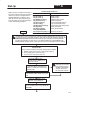
%1)&8 3(!3 !-$ 2)'-!+2 !1% ".3( !#3)5%
(%#* $&+* % "* D
.-31.++%1 3!13%$ "43 ,.3.1
1.3!3)-'
+*&+* ('+$-
$)2/+!82 9
& $&+* % "* )2 2%3 3. 9 .-+8 3(% /1.'1!, *%8/!$ ,.$4+% *(* "433.- 6)++ 23!13
3(% ,.3.1
(%#* ,.3.1
D
%1)&8 3(!3 ,.3.1 )2 #.--%#3%$ /1./%1+8
(%#* &1%04%-#8 2.41#% ('+$- %##$
D
%1)&8 3(!3 &1%04%-#8 2)'-!+ )2 /1%2%-3 !3 3%1,)-!+ "+.#* : 2)'-!+
, 2)'-!+
D
%1)&8 3(!3 1%2%3 1%04%-#)%2 !1% 2%3 /1./%1+8
(%#* #.-31.+ )-/43 2)'-!+2
D
%1)&8 3(!3 !-$ !1% #.11%#3 %&%1 3. 3(% #(!13 !3 3(% %-$ .& (!/3%1 (%#* /!1!,%3%1 2%33)-'2
.3.1 -.3 !##%+%1!3)-' /1./%1+8
D
%1)&8 3(!3 (' "* )2 2(.6)-' $%2)1%$ &1%04%-#8 2.41#%
D
%1)&8 3(!3 $*($" ('+$- )2 3(% $%2)1%$ 5!+4%
(%#* ,.3.1
D
%1)&8 3(!3 ,.3.1 )2 #.--%#3%$ /1./%1+8
D
%1)&8 3(!3 -. ,%#(!-)#!+ /1."+%,2 %7)23
(%#* /!1!,%3%1 2%33)-'2
!- -.3 ./%1!3% )- 9 ,.$%
D
%1)&8 3(!3 " !# .1 " !# )2 2%3 /1./%1+8
D
%1)&8 3(!3 +(($* !#!* )2 2%3 /1./%1+8
D
%1)&8 3(!3 %%)* %"*) )2 2%3 /1./%1+8
%1)&8 3(!3 $&+* % "* )2 2%3 3. 9
%1)&8 3(!3 /.6%1 (!2 "%%- #8#+%$ &.1 !".5% #(!-'% 3. 3!*% %&&%#3
%1)&8 3(!3 ".3( !-$ 26)3#(%2 !1% #+.2%$ 2),4+3!-%.42+8
6–3
Brake Module
BR+
F
r
e
q
u
e
n
c
y
DC+
DC-
L1/R
T1/U
L2/S
T2/V
L3/T
T3/W
R
e
f -10 to +10V
e or
Potentiometer
r
e
n or
c
4 - 20 mA
e
Reverse
Start
Stop
Common
6–4
Capacitor Module
BR-
GND/PE
TB3 - 1
Control
Power
TB3 - 2
Bus
Voltage
Circuitry
TB3 - 3
(Common)
Motor
GND/PE
Current
Circuitry
Fault Feedback
TB3 - 4
Program Keypad
Module
CPU
TB3 - 5
TB3 - 6
TB3 - 8
TB3 - 7
Opto
Isolator
Relay
Circuitry
TB3 - 9
Customer
TB3 - 10 Programmable
Output
TB3 - 11
$ " "!
Tables A.1 and A.2 contain information that is unique to each SSC Controller rating. Table A.3
contains information that applies to all Controller ratings.
"! " ! " ! #"
!
! ! 10,10 1..#*0 4
+3#. &//&, 0&+* 00/
! ! % /# +0+. 0&*$ ' ! *,10 +(0 $# .#-1#*!5
&*$(# % /# *" %.## % /# 6
,#. 0&+* ( *$# 7
*,10 '
" ++(&*$ #0%+"
# !
+*2#!0&+* ++(#"
* ++(#"
À
&0% #40#.* ( 5* )&! . '# +"1(# &0%+10 #40#.* ( 5* )&! . '# +"1(# "! " ! " ! #"
!
! 10,10 1..#*0 4
+3#. &//&, 0&+* 00/
! ! % /# +0+. 0&*$ ' ! *,10 +(0 $# .#-1#*!5
%.## % /# 6
,#. 0&+* ( *$# *,10 '
" ++(&*$ #0%+"
+*2#!0&+* ++(#"
* ++(#"
# ! À
À
&0% #40#.* ( 5* )&! . '# +"1(# &0%+10 #40#.* ( 5* )&! . '# +"1(# A–1
Output Voltage (V)
Adjustable from 0V to input voltage
Output Frequency (Hz)
0 to 240 Hertz Programmable
Efficiency (%)
Transient Protection
97.5% (Typical)
Standard 2 kV (Optional 6 kV using MOV module). See accessories on page A-5.
Enclosure
IP 20
Ambient Temperature
0_C to 50_C
Storage Temperature
Ć40_C to 85_C
Relative Humidity
0 to 95% (non condensing)
Vibration
1.0 G Operational - 2.5 G Non-operational
Shock
15 G Operational - 30 G Non-operational
Altitude
1,000 m (3,300 ft.) without derating
Control Input Type
For dry contact closure input - the controller has an internal 12V power supply that provides
10-mA (typical) current flow.
Also accepts open collector/solid state input with maximum leakage current of 50 mA
Start, Stop, Forward/Reverse
Configurable inputs for 2 or 3 wire control
SW1, SW2, SW3
Configurable Inputs for control of 8 preset speeds and 2 Accel/Decel times
Approvals
UL508C
Designed to meet these standards
CSA 22.2
ÎÎ
Î
ÎÎ
ÎÎ
Î
ÎÎ
Î
ÎÎ
ÎÎ
Î
ÎÎ
ÎÎÎ
ÎÎ
Î
89/336/EECÀ
IEC 146-1-1
FCC Class AÀ and BÀ
VDE 0871À and 0875À
External Speed Potentiometer
Analog Input (4 to 20mA)
Analog Input (-10 to +10 V DC)
1K to 10K Ohms, 2 Watts Minimum
Input lmpedance 250 Ohms
Input Impedance 100 K Ohms
Programmable Output
(Form C Relay contact)
À
With external filters.
A–2
Resistive rating: 0.4A @125V AC, 0.2A @ 230 V AC, 2A @ 30V DC
Inductive rating: 0.2A @ 125V AC, 0.1A @ 230V AC, 1A @30V DC
PWM Algorithm
Sine Weighted PWM with Harmonic Compensation
Switching Device (3-Phase Output)
IGBT (Intelligent Power Module)
V/Hz Ratio
Programmable
Carrier Frequency
Adjustable from 2kHz to 8kHz in 100 Hz Increments (Factory default is 4 kHz)
DC Boost
Adjustable - Select from a family of Boost Curves
Current Limiting
Trip Free Operation, CoĆordinated for Controller and Motor Protection - Programmable from
20% to 190% of Controller Output Current
Motor Protection
I2t Overload Protection - 150% for 60 seconds, 200% for 30 seconds
Overload Pattern #0
Flat response over speed range (no speed compensation)
Overload Pattern #1
Speed compensation below 25% of Base Speed
Overload Pattern #2
Speed compensation below 100% of Base Speed
Acceleration/Deceleration Time(s)
0.1 to 600 Seconds
S-Curve Accel/Decel Time(s)
0 to 100% of Accel/Decel time - not to exceed 60 seconds
Stopping Modes
3 modes (programmable)
Ramp to stop
0.1 to 600 seconds
Coast
Stops all PWM Output
DC Brake to stop
Applies DC Voltage to the Motor for 0 to 15 seconds
Overcurrent
Excessive Temperature
Over/Under Voltage
Control Ride Through
Ground Short
Faultless Ride Through
Output Short Circuit
200% hardware limit, 300% instantaneous fault
Embedded temperature sensor trips if heatsink temperature exceeds 95°C
DC Bus voltage is monitored for safe operation.
For controllers rated at input voltage 200-240 VAC, overvoltage trip occurs at 410 VDC bus
voltage (equivalent to 290 VAC incoming line voltage).
For controllers rated at input voltage 380-460 VAC, overvoltage trip occurs at 815 VDC bus
voltage (equivalent to 575 VAC incoming line voltage ).
For controllers rated at input voltage 200-240 VAC, undervoltage trip occurs at 210 VDC bus
voltage (equivalent to 150 VAC incoming line voltage).
For controllers rated at input voltage 380-460 VAC, undervoltage trip occurs at 390 VDC bus
voltage (equivalent to 275 VAC incoming line voltage).
Minimum ride through is 0.5 seconds - typical value 2 seconds
Any output short to ground, detected prior to start
100 Milliseconds
Any output phase to phase short
Programmer
Optional, Removable Program Keypad Module
Type of Display
6 character LED - two digit parameter number and four digit value
Local Controls
SPEED, RUN, STOP, and DIRECTION controls
A–3
% # " !!
" ! " !
$ !!
À
" ! " !
$ !!
" ! " !
$ !!
À
Use the drilling template at the back of the manual for mounting the controller.
A–4
& ÁÁÁÁÁÁÁÁÁÁÁÁÁÁÁÁÁÁÁÁÁÁÁÁÁÁÁÁ
ÁÁÁÁÁÁÁÁÁ
ÁÁÁÁÁ
ÁÁÁÁÁ
ÁÁÁÁ
ÁÁÁÁÁ
ÁÁÁÁÁ
ÁÁÁÁÁÁÁÁÁÁÁÁÁÁÁÁÁÁÁÁÁÁÁÁÁÁÁÁ
ÁÁÁÁÁÁÁÁÁ
ÁÁÁÁÁ
ÁÁÁÁÁ
ÁÁÁÁ
ÁÁÁÁÁ
ÁÁÁÁÁ
ÁÁÁÁÁÁÁÁÁ
ÁÁÁÁÁ
ÁÁÁÁÁ
ÁÁÁÁ
ÁÁÁÁÁ
ÁÁÁÁÁ
ÁÁÁÁÁÁÁÁÁ
ÁÁÁÁÁ
ÁÁÁÁÁ
ÁÁÁÁ
ÁÁÁÁÁ
ÁÁÁÁÁ
ÁÁÁÁÁÁÁÁÁ
ÁÁÁÁÁ
ÁÁÁ
ÁÁÁ
ÁÁÁÁÁ
ÁÁÁÁÁ
ÁÁÁÁ
ÁÁÁÁÁ
ÁÁÁÁÁ
ÁÁÁÁÁ
ÁÁÁ
ÁÁÁ
ÁÁÁÁÁ
ÁÁÁÁÁ
ÁÁÁ
ÁÁÁ
ÁÁÁÁÁ
ÁÁÁÁÁ
ÁÁÁ
ÁÁÁ
ÁÁÁÁÁ
ÁÁÁÁÁ
ÁÁÁ
ÁÁÁ
ÁÁÁÁÁ
ÁÁÁÁÁ
ÁÁÁ
ÁÁÁ
ÁÁÁÁÁ
ÁÁÁÁÁ
ÁÁÁ
ÁÁÁ
ÁÁÁÁÁ
ÁÁÁÁÁ
ÁÁÁ
ÁÁÁ
ÁÁÁÁÁ
ÁÁÁÁÁ
ÁÁÁ
ÁÁÁ
ÁÁÁÁÁ
ÁÁÁÁÁ
ÁÁÁ
ÁÁÁ
ÁÁÁÁÁ
ÁÁÁÁÁ
ÁÁÁ
ÁÁÁ
ÁÁÁÁÁ
ÁÁÁÁÁ
ÁÁÁ
ÁÁÁ
ÁÁÁÁÁ
ÁÁÁÁÁ
ÁÁÁ
ÁÁÁ
ÁÁÁÁÁ
ÁÁÁÁÁ
ÁÁÁ
ÁÁÁ
ÁÁÁÁÁ
ÁÁÁÁÁÁÁÁ
ÁÁÁ
ÁÁÁÁÁ
""!"
For All Controller Ratings – 0.37 to 2.2kW (1/2 to 3 HP)
#!! #"
$#
#
#
*
&
*
&
*
&
À
'
!
$
$
#!"
#'
#!"
#!
$
# # # # # À
#"( )!' $#'%$""%
# !#" ""!"
ÁÁÁÁÁÁÁÁÁÁÁÁÁÁÁÁÁÁÁÁÁÁÁÁÁÁÁÁÁ
ÁÁÁÁÁÁÁ
ÁÁÁÁÁÁÁÁ
ÁÁÁÁÁÁÁÁÁ
ÁÁÁÁÁÁÁ
ÁÁÁÁÁÁÁÁÁÁÁÁÁÁÁÁÁÁÁÁÁÁÁÁÁÁÁÁÁ
ÁÁÁÁÁÁÁ
ÁÁÁÁÁÁÁÁ
ÁÁÁÁÁÁÁÁÁ
ÁÁÁÁÁÁÁ
ÁÁÁÁÁÁÁÁÁÁÁÁÁÁÁÁ
ÁÁÁÁÁÁÁ
ÁÁÁÁÁÁÁÁ
ÁÁÁÁÁÁÁ
ÁÁÁÁÁÁÁÁ
ÁÁÁÁÁÁÁ
ÁÁÁÁÁÁÁÁÁ
ÁÁÁÁÁÁÁ
ÁÁÁÁÁÁÁ
ÁÁÁÁÁÁÁ
For Controller Ratings – 0.37 to 2.2kW (1/2 to 3 HP)
# #
'$# !! ' $
%# $#
$
# # # # A–5
A–6
Index
4 %+.2%/$ 4 %+.2%/$ %)+0/ 2%-%)# !' !!' *)/-*' (%!)/ /!(+!-/0-! )'*# %)+0/
/* ( )'*# .'! /!$ ++-*1'. 0/* -!./-/
-!./-/ /%(! -!./-/ /-%!. !)'! -&! /* ./*+ $*' '!1!' !"0'/. -!.!//%)# /* !/!-(%)%)# *)/-*''!- %)"*-(/%*) %#)*./%. %(!).%*). %.+'3 #-*0+ +-(!/!-. *)/-*''!- "!/0-!. *)/-*''!- .+!%"%/%*). 3)(% -&! *))!/%*) 3)(% -&! -!.%./*- !""!/. '*)# (*/*- '! '!)#/$. !'!/-*.//% %.$-#! '*& %#-( -)$ %-0%/ %.*))!/ +%/*- (* 0'! *))!/%)# --%!- "-!,0!)3 +2( /'*# )0(!- !.-%+/%*) $)#%)# .! "-!,0!)3 "-*( "/*-3 !"0'/ '!-%)# "0'/ '!-%)# "0'/. *)/-*' 2%-%)#
)'*# %#)' *''*2!- (* !' -!.!/ +!! (* !' *)/-*' 2%-%)# -!,0%-!(!)/.
)'*# %#)' *''*2!- (* !' -!.!/ +!! (* !' 0--!)/ '%(%/%)# 0--!)/ -/%)# ")+0(+ 1*'/.4 +//!-). "0'/ 0""!- "0'/ %)"*-(/%*) /-*0'!.$**/%)# "0'/ "0'/. '!-%)# "-!,0!)3 %+.2%/$ "-!,0!)3 .*0-! .!'!/%*)
)'*# %#)' *''*2!- (* !' -!.!/ +!! * !' -!.!/ +!! (* !' "0.%)# )+0/ #!)!-' +-!0/%*). #-*0) %)# %)+0/ (* ! .!'!/%*) %)./''/%*) -!*((!) /%*). %)./''/%*) +-!0/%*). %)./''%)# *)/-*''!- %)./''%)# /$! *)/-*''!- I–1
Index
%"&%0 *)-&1 %"&"%-% $*& %','* $ $& ,!+ ,+ *'%%&,"'&+ '* '&,*'$$* "&+,$$,"'& *+,,"& ,' ,'*1 -$,+ *.*+ &%($, "&'*%,"'& '(*,"& '&,*'$$* /",!'-, (*' *% #1( %'-$ '(*,"& '&,*'$$* /",!'-, #1( '-,(-, '&,,+ '-,(-, "+'&&,"'& '-,(-, *,"& + +"& $ (!+ ,!* (!+ '.*$' (*',,"'& (*%,*+
"+($1 *'-( "+($1 '&$1 (*' *% *'-( (',&,"'%,* /"*"& ('/* /"*"& (*-,"'&+ (*+, *)-&"+ (*+, *)-&1 (*' *% *'-( (*%,*+ (*' *% #1( %'-$
+*"(,"'& "+($1 %' ,-*+ #1 +*"(,"'&+ (*' *% %' *%'.$ (*' *% $'# (*' *% %' (*' *%%"& 0%($ +,(+ (*' *%%"& (*%,*+ I–2
-*. +#"( *)-&1 +("","'&+ (*',,"'& +("","'&+ +"& $ (!+
&."*'&%&,$ "&(-,'-,(-, *,"& + +("","'&+ ,!* (!+ "&(-,'-,(-, *,"& +
+("","'&+ ,!* (!+ &."*'&%&,$ +("","'&+ '* $$ '&,*'$$* *,"& + &."*'&%&,$ +,&*+ '%($"& +,*, +,'(("& +,'* ,%(*,-* ,*%"&$ $'#+
'& & ,!* ,'*)- *,"& + ,*'-$+!'',"& -$, +*"(,"'&+ ."*,"'& .'$, *,"& /"*"&
'&,*'$ & +" &$ -+ *)-"*%&,+ "&(-, $"& -++ ('/* ,*%"&$ $'#+ Attach template to mounting surface
and drill four (4) 4.5 mm (0.177 inches) diameter holes.
Dimensions are in millimeters [inches].
44.6C:*-4.A * "7,3?.44 *=<75*<276 +=;26.;; 1*; +..6 1.48260 2<; ,=;<75.:; 258:7>. 8:7-=,<2>2<A *6- 9=*42<A /7:
57:. <1*6 A.*:; '. -.;206 5*6=/*,<=:. *6- ;=887:< * +:7*- :*60. 7/ *=<75*<276 8:7-=,<; ?7:4-?2-. $1.A
26,4=-. 4702, 8:7,.;;7:; 87?.: *6- 57<276 ,76<:74 -.>2,.; 78.:*<7: 26<.:/*,.; ;.6;7:; *6- * >*:2.<A 7/ ;7/<?*:.
"7,3?.44 2; 76. 7/ <1. ?7:4-; 4.*-260 <.,167470A ,758*62.;
'7:4-?2-. :.8:.;.6<*<276
:0.6<26* S =;<:*42* S =;<:2* S *1:*26 S .402=5 S :*B24 S =40*:2* S *6*-* S 124. S 126* " S 7475+2* S 7;<* "2,* S :7*<2* S A8:=; S B.,1 ".8=+42, S .65*:3
,=*-7: S 0A8< S 4 #*4>*-7: S 264*6- S :*6,. S .:5*6A S :..,. S =*<.5*4* S 76-=:*; S 760 760 S =60*:A S ,.4*6- S 6-2* S 6-76.;2* S :.4*6- S ;:*.4 S <*4A
*5*2,* S *8*6 S 7:-*6 S 7:.* S =?*2< S .+*676 S *4*A;2* S .@2,7 S .<1.:4*6-; S .? ).*4*6- S 7:?*A S *32;<*6 S .:= S 12428826.; S 74*6- S 7:<=0*4
=.:<7 "2,7 S !*<*: S "75*62* S "=;;2*# S #*=-2 :*+2* S #260*87:. S #47>*32* S #47>.62* S #7<1 /:2,* ".8=+42, S #8*26 S #?.-.6 S #?2<B.:4*6- S $*2?*6 S $1*24*6$=:3.A S %62<.- :*+ 52:*<.; S %62<.- 260-75 S %62<.- #<*<.; S %:=0=*A S &.6.B=.4* S (=07;4*>2*
44.6C:*-4.A .*-9=*:<.:; #7=<1 #.,76- #<:..< 24?*=3.. ' %# $.4 C *@ C
=+42,*<276 =4A #=8.:;.-.; =+42,*<276 C .+:=*:A *6- % =6. CC
78A:201< 44.6C:*-4.A 758*6A 6, * "7,3?.44 6<.:6*<276*4 ,758*6A :26<.- 26 %#
I-1