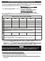
1
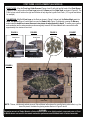
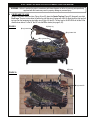
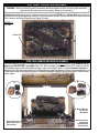
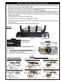
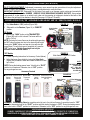
Owner’s Manual
DOUBLE FACE CHILLBUSTER 7
Decorative Vented/Unvented Gas Log Set
General Assembly, Installation, and Operation Instructions
12028 E. PHILADELPHIA ST.
WHITTIER, CA CALIFORNIA 90601 U.S.A.
THE GAS LOG COMPANY
www.rasmussen.biz
Report # 10-37
REV: DFC7-01.11
Last Printed 1/3/2011 8:39
ATTENTION! READ INSTRUCTIONS CAREFULLY BEFORE ASSEMBLY OR USE
“Chillbuster Evening Embers” Models: DFC7 (33,000 Btu); 18, 24 or 30, -ME, -SE, or -RE Natural Gas (N)
or Propane Burners (P) with HH18, 24 or 30 Log Sets.
WARNING: If the information in this manual is not
followed exactly, a fire or explosion may result causing property damage, personal injury or loss of life.
— Do not store or use gasoline or other flammable
vapors and liquids in the vicinity of this or any
other appliance.
This is an unvented gas-fired heater. It uses air
(oxygen) from the room in which it is installed.
Provisions for adequate combustion and ventilating
air must be provided. Refer to pages 5 and 6.
INSTALLER: Leave this manual with the appliance.
CONSUMER: Retain this manual for future reference.
— WHAT TO DO IF YOU SMELL GAS
• Do not try to light any appliance.
• Do not touch any electrical switch; do not use
any phone in your building.
• Immediately call your gas supplier from a
neighbor’s phone. Follow the gas supplier’s
instructions.
• If you cannot reach your gas supplier, call the
fire department.
This appliance may be installed in an aftermarket,
permanently located, manufactured (mobile) home,
where not prohibited by local codes.
— Installation and service must be performed by a
qualified installer, service agency or the gas
supplier.
Installation must conform with local codes or, in the
absence of local codes, with the National Fuel Gas Code,
ANSI Z223.1/NFPA 54.
This appliance is only for use with type of gas
indicated on the rating plate. This appliance is not
convertible for use with other gases. Field conversion
is not permitted. Gas type conversion may only be
accomplished at the factory. Please contact Rasmussen
for details.
WARNING
This appliance is for installation only in a solid-fuel burning masonry or UL 127 factory-built fireplace or in a listed
ventless firebox enclosure. It has been design certified for these installations. Exception: DO NOT install this
appliance in a factory-built fireplace that includes instructions stating it has not been tested or should not be used
with unvented gas logs.
•
•
•
In the Commonwealth of Massachusetts:
Installation must be performed by a licensed plumber or gas fitter.
The chimney flue damper, when used with gas logs, will be welded open or completely removed.
A CO detector shall be installed in the room where the appliance is installed.
IMPORTANT:
An unvented room heater having an input rating of more than 10,000 Btu per hour shall not be installed
in a bedroom or bathroom. Do not install this appliance in a bedroom or bathroom.
The Minimum Fireplace Size (in inches) in which this Chillbuster set is to be installed must be as follows:
Set Size
Model Number
BTU/hour Front Width Rear Width
Depth
Height
18
DFC7- (ME,SE,RE) - (N,P)
33,000
24”
24”
16”
17”
24
DFC7- (ME,SE,RE) - (N,P)
33,000
30”
30”
16”
17”
30
DFC7- (ME,SE,RE) - (N,P)
33,000
36”
36”
16”
CHILLBUSTER™ Contemporary Gas Heaters are certified to the following standards:
• UNVENTED ROOM HEATER ANSI - Z21.11.2b-2010
• VENTED DECORATIVE APPLIANCE - ANSI Z21.60b-2004
1
17”
•
•
•
•
•
•
•
•
•
•
•
•
•
•
•
•
•
•
•
•
•
•
IMPORTANT INFORMATION
Due to high temperatures, the appliance should be located out of traffic and away from furniture and draperies.
Children and adults should be alerted to the hazard of high surface temperatures and should stay away to avoid burns or
clothing ignition.
Young children should be carefully supervised when they are in the same room with the appliance.
Do not place clothing or other flammable material on or near the appliance.
Any safety screen or guard removed for servicing an appliance must be replaced prior to operating the heater.
Installation and repair should be done by a qualified service person. The appliance should be inspected before use and at
least annually by a professional service person. More frequent cleaning may be required due to excessive lint from
carpeting, bedding material etc. It is imperative that control compartments, burners and circulating air passageways of the
appliance be kept clean.
WARNING: Any change to this heater or its controls can be dangerous.
This appliance is intended for supplemental heating. It should not be used as a primary heat source for a dwelling.
WARNING: Failure to keep the primary air opening(s) of the burner clean may result in sooting and property damage.
Keep appliance area clear and free from combustible materials, gasoline and other flammable vapors and liquids.
DO NOT use this room heater if any part has been under water. Immediately call a qualified service technician to inspect
the room heater and to replace any part of the control system and any gas control that has been under water.
WARNING: Before installing in a solid-fuel burning fireplace, the chimney flue and firebox must be cleaned of soot,
creosote, ashes and loose paint by a qualified chimney cleaner.
WARNING: Do not allow fans to blow directly into the fireplace. Avoid any drafts that alter burner flame patterns.
WARNING: Do not use a blower insert, heat exchanger insert or any other accessory not approved for use with this heater.
A fireplace screen must be in place when the appliance is operating and, unless other provisions for combustion air are
provided, the screen shall have an opening(s) for introduction of combustion air.
Solid fuels shall not be burned in a fireplace where this CHILLBUSTER™ heater is installed.
WARNING: Glass doors must be fully opened when appliance is in operation to allow for safe combustion, cooling of
components and venting.
Any outside air ducts and/or ash dumps in the fireplace shall be permanently closed at the time of appliance installation.
State or local codes may only allow operation of this appliance in a vented configuration. Check your state or local codes.
DO NOT use this appliance, in the vent-free application, in sleeping quarters, bathrooms or recreational vehicles. This
appliance may be used in sleeping quarters and bathrooms if used in a vented application, subject to local codes.
Avoid contact with the objects, chassis or another part which may be hot during operation.
This appliance is equipped with an ODS (Oxygen Depletion Sensor) pilot light safety system , which is designed to
shut the appliance off in the absence of inadequate fresh air. Additional ventilation may be obtained by opening a
window an inch or two, or a door to another room. See Page 14 for nuisance shutdown issues and correction.
CARBON MONOXIDE POISONING MAY LEAD TO DEATH
When used without fresh air, decorative gas appliances may give off carbon monoxide, an odorless, colorless,
poisonous gas. Some people, pregnant women, persons with heart or lung disease, anemia, persons under the
influence of alcohol and persons who live at high altitudes are more affected by carbon monoxide than others.
Early signs of carbon monoxide poisoning resemble the flu and include; headache, dizziness and/or nausea. If you
have these symptoms, the burner or the appliance may not be installed or working properly, or the flue may be
blocked. GET FRESH AIR AT ONCE! Verify that the gas log set is properly arranged and have the heater and
chimney flue serviced before using again.
WARNING
During manufacturing, assembly and packaging, various components of CHILLBUSTER™ are exposed to certain oils
or films. These are not harmful but may produce annoying smoke and smells as they are burned off during the initial
operation of the appliance, possibly causing headaches, eye or lung irritation. This is a normal occurrance and only
temporary. The initial break-in operation should last 2-3 hours with the burner at the highest setting. Provide maximum
ventilation by opening windows, doors and the chimney flue (if using a vented model) to allow odors to dissipate.
The only odor remaining after this initial break-in period will be the normal odors associated with the combustion of
Natural or Propane Gas and/or related to your indoor environment (see page 15).
WARNING—Proposition 65 Statement
If not installed, operated and maintained in accordance with these instructions, this product could expose you to
substances in fuel or from fuel combustion which are known to the State of California to cause cancer,
birth defects or other reproductive harm.
2
PARTS LIST
REQUIRED TOOLS AND MATERIALS
Adjustable Wrench and Pipe Wrench. Pipe Sealing compound is required if fittings not already pre-threaded with Teflon tape to
prevent gas leaks. DO NOT use Teflon tape or pipe compound on other tapered fittings.
1. “EASY” Safety Valve Knob
1b. Valve Knob Extender “ME” Models
(STV-KE2)
2. Valve Plug (“ME” Models) (also used
when replacing, servicing or upgrading
“EASY” Safety Valve)
2a. Remote Ready Solenoid*
(-SE Models) (STV-LS)
2b. Variable Flame Height Motordrive*
(-RE Models) (STV-VMD)
3. “EASY” Safety Valve (STV-10)
*See following page for wireless
accessories.
4.
5.
6.
7.
7b.
7.
8.
9.
10.
11.
12.
13.
3/8” X 1/2” Pipe Nipple
3/8” - 90° Elbow
Regulator (R1-3.5 Narural Gas/ R1-10.5
Propane)
Gas Supply Input (A2)
Orifice Holder (A2)
Grate (DFC7 OLD STYLE / DFC7E)
Damper Clamp(DC1)
Flex Connector (SSCB-18)
3/8” x 1/2” FIP Flared Brass Fitting (A1)
Burner (Pilot Attached) (CEB-24R)
Ember Lifter
1/4” x 24” Tubing
14. 3/8” x 13” Tubing
15. Thermocouple Lead
16. 48 x 6x 6b Connector Fitting
17. Pilot Assembly (see page 13)
18. Piezo Igniter Assembly
18b. Piezo Wire (misc. part)
18c. Peizo Pal Nut
19. Orifice Natural (#35) Propane (#50)
20. Volcanic Ash (VA5)
21. Embers (EMCB)
22. Rating/Serial Plate
23. Warning Plate
10
13
14
14
15
8
16
5
6
7
4
7b
3
18b
19
18
2a
1
2b
2
18c
1b
11
9
17
Table of Contents
12a
12
15
23
20
22
21
Pages 1-2………….Warnings and Standards
Pages 3-4………...….Parts and Accessories
Page 5………………....Spacing Calculations
Page 6………...Combustion Air Calculations
Page 7……...………….……….…Clearances
Page 8-9…………….……………..Installation
Pages 10-11…....……….…...Log Placement
Page 12……...Remote Receiver Placement
Pages 13-14…...…...Lighting and Operation
Pages 15-16....Maintenance and Operation
Page 17……………………..Troubleshooting
Page 18……………………….…….Warranty
WARNING: Any change to this appliance or its controls can be dangerous
3
LOGS AND ACCESSORIES
1.
2.
3.
4.
5.
6.
7.
Center log for DFC7-18”, 24” and
30” (U12)
Front log for DFC7-18” (H21a) 2 ea.
Front log for DFC7-24” (H22a) 2 ea.
Front log for DFC7-30” (H23a) 2 ea.
Right and Left top log for DFC7-18”
(CH3a)
Right and Left top log for DFC7-24”
and DFC7-30 (BE2a )
V1/V2 Valve Assembly
(each sold separately)
8.
9.
10
11
V1 Valve Assembly
V2 Valve Assembly
Short Valve Key (K1)
Long Valve Key (K2)
(V1/V2 Valve Assembly)
12. Stand Alone Crackler, Switch and
Remote Housing (CF5SA1)
(sold separately, see page 12 also)
13. Wireless Remote Transmitter
Devices For “-SE” Models (each
sold separately)
13. a. Wireless Hand-Held ON/OFF Remote (SR-2R)
b. Wireless Hand Held ON/OFF Remote with
Thermostat (THR-2R)
c. Wireless Wall Timer (30/60/120 Minutes) (WT-2R)
d. Wireless Wall Thermostat (TS-2R)
e. Wireless Wall Switch (WS-2R)
14. Wireless Hand Held Variable Remote for “-RE” Models
(STR-RMD)
15. Remote Receiver for “-SE” or “-RE” models (BPR3)
16. Remote Housing (RH2) (sold separately)
1
5
6
Gas Supply Valves (see page 8 and 9)
11
(Sold Separately)
2
7
8
9
10
3
12
4
13
A.
B.
C.
D.
E.
14
15
12
4
VENT FREE APPLICATIONS ● SPACING CALCULATIONS
This heater shall not be installed in a “confined” space or unusually tight construction unless provisions are
provided for adequate combustion and ventilation air.
The “National Fuel Gas Code, ANSI Z223.1/NFPA 54” defines a confined space as a space whose volume is less than
50 cubic feet per 1000 Btu per hour (4.8 m³ per kW) of the aggregate input rating of all appliances installed in that space
and an unconfined space as a space whose volume is not less than 50 cubic feet per 100 Btu per hour (4.8 m³ per kw) of
the aggregated input rating of all appliances installed in that space. Rooms communicating directly with the space in
which the appliances are installed, through openings not furnished with doors, are considered a part of the unconfined
space.
Calculations to Determine Confined or Unconfined Space:
1. Determine number or rooms (including adjoining rooms with odorless passageways or ventilation grates.)
Example: Living room/Dining Room + Kitchen
2. Determine the Total Volume of the Space (Width x Length x Height).
Example: Living room/Dining Room 14’ x 20’ x 8’ = 2240 cu ft.
Kitchen
8’ x 12’ x 8’ = 768 cu ft.
Total Volume of Space
3008 cu ft.
3. Divide the total volume of space by 50 cu ft to determine the Maximum Supportable Btu/Hr.
Example: 3008 cu ft ÷ 50 = 60.160 x 1000 = 60,160
Maximum Supportable Btu/Hr. =
60,160 Btu/Hr.
4. Add the rated (Btu/hr) of all fuel burning appliances in the “space” to determine Actual Btu/Hr. used.
Example: Vent free gas log heater 40,000 Btu/Hr.
+ Gas water heater
32,000 Btu/Hr.
= Actual Btu/Hr. Used
72,000 Btu/Hr.
Note: Do not include direct vent gas appliances.
5. Compare Maximum Supportable Btu/Hr to Actual Btu/Hr Used.
• If the Actual Btu/Hr used. is greater than the Maximum Supportable Btu/Hr. then the space is CONFINED.
• If the Actual Btu/Hr used. Is less than the Maximum Supportable Btu/Hr. then the space is UNCONFINED.
Example: Maximum Supportable Btu/Hr = 60,160 Btu/Hr.
Actual Btu/Hr. Used
= 72,000 Btu/Hr.
Difference
= 11,840 Btu/Hr. = Excess Non-Supportable Btu/Hr.
Because the Actual Btu/Hr used Exceeds the Maximum Supportable Btu/Hr in this example, the space is considered
a Confined Space requiring you to either increase the Maximum Supportable Btu/Hr by the difference, in this case
11,840 Btu/Hr. or decrease the Actual Btu/Hr used by the same amount. You may also choose to operate your
Chillbuster™ as a Vented Appliance instead. (See notes and warnings regarding vented installation on Page 7)
Adequate Combustion And Ventilation Air Options:
•
Increasing the Maximum Supportable Btu/Hr.
1. Add to the number of rooms which comprise the “Space”. To do this you must either completely remove the door
to an adjoining room, or provide two permanent ventilation grills; one within 12” of the ceiling and another within
12” of the floor.
2. Provide extra fresh air using ventilation grills and ducts to the outdoors. You must provide two permanent openings. One within 12” of the ceiling and another within 12” of the floor. Connect these directly to the outdoors or
spaces open to the outdoors, e.g., attics or crawl spaces. If this route is chosen you MUST follow the National
Fuel Gas Code NFPA 54/ANSI Z223.1, Section 5.3, Air for Combustion and Ventilation for required size of
ventilation grills or ducts.
•
Lower the Actual Btu/Hr used by relocating other gas burning appliances outside the “space” or installing a lower
Btu/Hr heater. In the example, the maximum Btu/Hr. of the heater could be no more than 28,160 Btu/Hr.
5
VENT FREE APPLICATIONS ● COMBUSTION AIR CALCULATIONS
For our example, we have chosen to add to our Total Volume of the Space by removing the door to an adjoining study
and increasing our Maximum Supportable Btu/Hr by the volume of the additional room. The new “space” calculations,
including the additional adjoining room are: Living room/Dining room & Kitchen 3008 cu ft
Study (9' x 10' x 8')
720 cu ft
Total volume of space
3728 cu ft
The new Maximum Supportable Btu/Hr = (3728 cu ft ÷ 50 cu ft ) x 1000 = 74,560 Btu/Hr
74,560 Btu/Hr = Maximum Supportable Btu/Hr
-72,000 Btu/Hr = Actual Btu/Hr Used
2560 BTU/Hr = Remaining supportable BTU/H
Because the Actual Btu/Hr used is now less than the Maximum Supportable Btu/Hr, the space is considered an
Unconfined Space. No additional fresh combustion and ventilation air would be required.
COMBUSTION AIR CALCULATIONS WORKSHEET
1.
Room
Width
Length
Height
W x L x H =Vol.(ft³)
1a.
1a.
1b.
1b.
1c.
1c.
1d.
1d.
2. Total Volume (ft³) The Sum of Volume of all rooms (add lines 1a. thru 1d.).
2.
3. Max Supportable Btu/Hr = Total Volume (ft³) ÷ 50 x 1000 (divide line 2. by 50 then multiply
by1000)
3.
4. 4a.
Btu/hr 4b.
Btu/hr 4c.
Btu/hr 4d.
Btu/hr
Actual Btu/hr used = The sum of Btu/hr of all fuel burning appliances inside the space identified 4.
as rooms 1a. thru 1b (add line 4a thru 4d).
5. (Maximum Supportable Btu/Hr) minus (Actual BTU/hr Used) (Subtract line 4. from line 3. )
5.
*
* If Line 5 is greater than zero, the Actual Btu/Hr Used is less than the Maximum Supportable Btu/Hr and the
space is considered UNCONFINED. No additional fresh combustion and ventilation is required.
* If Line 5 is zero or less, the Actual Btu/Hr Used is greater than Maximum Supportable Btu/Hr and the space is
CONFINED. You must either increase the Maximum Supportable Btu/Hr, decrease the Actual Btu/Hr Used or
operate as a Vented Appliance (See notes and warnings regarding vented installation on Page 5).
WARNING:
If the area in which the heater may be operated is smaller than that defined as an unconfined space or if the
building is of unusually tight construction**, provide adequate combustion and ventilation air by one of the
methods described in the National Fuel Gas Code, ANSI Z223.1 / NFPA 54, or applicable local codes.
**Unusually tight construction is defined as construction where;
a) Walls and ceilings exposed to the outside atmosphere have a continuous water vapor retarder with a rating of 1 perm
(6 x 10-11 kg per pa-sec-m²) or less with openings gasketed or sealed;
b) Weather stripping has been added on openable windows and doors; and
c) Caulking or sealants are applied to areas such as joints around window and door frames, between sole plates and
floors, between wall-ceiling joints, between wall panels, at penetrations for plumbing, electrical, and gas lines, and at
other openings.
6
VENT FREE APPLICATIONS ● MINIMUM CLEARANCES TO COMBUSTIBLES
WARNING:
Be certain that combustible flooring material (i.e.; carpet, tile etc.) is not too close to this gas appliance. If this
appliance is at floor level or less than 6” above the floor, there must be at least 12” of noncombustible material
between the base of the fireplace and any combustible flooring.
When operated as a Vent Free Heater, the minimum clearances from the fireplace opening to combustible materials
must be maintained as outlined below .
NOTE:
MINIMUM CLEARANCES TO SIDE WALL AND CEILING
Clearances to Combustible Construction are those
distances required to ensure that a fireplace mantel or
facing will not catch fire. In most cases they should also
be adequate to prevent any discoloration or warping due
42”
to heat. However, each and every decorative gas appliance installation (CHILLBUSTER™ included) presents a
different and completely unique set of circumstances
involving many variables beyond the control of the manufacturer. These include paint or finish composition, previ15 1/2”
ous exposure to heat, methods and quality of construction, air flow patterns, glass doors, fans or blowers, etc.
Because of these variables, we cannot guarantee that
heat warping or discoloration will never occur. The potential for heat warping or discoloration may exist whether
you are burning an CHILLBUSTER™, some other manuSide wall: 15 1/2" from side of fireplace opening.
Ceiling: 42" from top of fireplace opening.
facturer's decorative gas appliance or even wood.
MANTEL CLEARANCE WITHOUT HOOD
MANTEL CLEARANCE WITH HOOD
A fireplace hood deflects heat away from the fireplace face and mantel, reducing the potential for heat related warping or discoloration.
The use of a fireplace hood is highly recommended.*
Horizontal projection from face of fireplace
Horizontal projection from face of fireplace
10”
30”+
8”
8”
6”
28”-30”
25”-28”
2.5”
.75”
20”-25”
12”-20”
2.5”
1.5”
Non combustible or heat resistant material (gypsum
board, marble, sheet rock, slate, tile etc.)
8” Minimum from top of firebox opening
10”
20”+
6”
17”-20”
15”-17”
12”-15”
10-12”
*Standard Fireplace Hood with
a minimum 4 inch horizontal
projection.
Distances from Top of
Firebox Opening to Underside
of Mantel
Distances from Top of
Firebox Opening to Underside
of Mantel
Height Above
Opening
Projection Out
From Face
Height Above
Opening
Projection Out
From Face
0-12"
12"-20"
20"-25"
25"-28"
28"-30"
30" plus
0"
3/4"
2 1/2"
6"
8"
10"
0-10"
10"-12"
12"-15"
15"-17"
17"-20"
20" plus
0"
1 1/2"
2 1/2"
6"
8"
10"
IF YOU CANNOT MEET THESE MINIMUM CLEARANCES YOU MUST OPERATE THE APPLIANCE AS A VENTED
APPLIANCE WITH CHIMNEY FLUE DAMPER OPEN. (See notes regarding vented installation on following page)
7
GENERAL INSTALLATION INSTRUCTIONS
WARNING: Failure to position the parts in accordance with these diagrams or failure to use only parts specifically
approved with this heater may result in property damage or personal injury.
The installation and the provisions for combustion and ventilation air must conform with The National Fuel Gas
Code ANSI Z223.1 / NFPA54, or The CSA B149.1, Natural Gas and Propane Installation Code, latest edition.
STEP ONE: PREPARATION (ALL MODELS)
FIGURE 2
1. Verify that the Valve Assembly is correctly matched to the set, burner,
and gas supply.
2. Insure that Fireplace Gas Supply is off (Figure 1A) .
Flue
3. Thoroughly clean fireplace floor of any ashes and have a qualified
chimney cleaner insure that the chimney flue and firebox are free of
soot, creosote, ashes and loose paint.
4. (VENTED INSTALLATIONS ONLY) Attach Damper Clamp (Figure 2A)
over edge of fireplace Damper Blade (Figure 2B) to prevent damper
A) Damper
Clamp
from closing accidentally. If unable to attach damper clamp, drill a hole
(or holes) in the damper or remove it completely.
FIGURE 1
A) Fireplace Gas
Log Lighter
Supply Valve
Valve Assembly (V1)
B) Damper Blade
Gas Supply
Pipe
Opening Height (17” Minimum)
Firebox Floor
Side View of Two sided Firebox
The minimum permanent free opening of the fireplace chimney or chimney damper must be 29 sq. inches based upon a
minimum chimney height of at least 10 feet. Solid Fuels shall not be burned in a masonry or UL 127 factory built fire
place where an CHILLBUSTER™ is installed.
LEAK TEST PROCEDURES
WARNING: DO NOT use an open flame to test leaks!
Create a mixture of equal parts soap and water. Apply to all the joints of the pipe fittings from the gas supply to
the burner. Turn on the gas supply valve for no longer than 3-5 seconds. If bubbles appear in the soap solution
applied to the joints, there is a leak. Turn off the gas supply valve and tighten those fittings. Repeat the procedure until no more bubbles appear. Test all joints. NOTE: Always perform a leak test any time the appliance has
been moved or disconnected from the gas supply line.
WARNING!
WARNING!
VENTED INSTALLATIONS
THE CHIMNEY DAMPER MUST BE WIDE OPEN AND FIXED IN A MANNER TO MAINTAIN A PERMANENT FREE
OPENING AT ALL TIMES AS OUTLINED ABOVE. THE AREA OF THE FLUE MUST BE NOT LESS THAN 1/10 THE AREA OF
THE FIREPLACE OPENING. THIS DECORATIVE GAS APPLIANCE MUST BE INSTALLED IN A FULLY VENTED METAL
OR MASONRY FIREPLACE WITH A WORKING FLUE THAT IS SAFE FOR BURNING A WOOD FIRE. THE FLUE MUST
BE FREE OF ANY OBSTRUCTIONS AND MUST EXHAUST ALL PRODUCTS OF COMBUSTION. DAMPER AND GLASS
DOORS MUST BE FULLY OPEN BEFORE LIGHTING OR BURNING FOR PROPER VENTILATION AND TO
PREVENT HEAT DAMAGE TO THE VALVE.
WARNING! CHECK FOR PROPER VENTING
A properly sized, unobstructed chimney will normally vent all products of combustion. Any odor or smoke detected inside
the room is an indication that the flue is not functioning properly.
SHUT OFF THE BURNER IMMEDIATELY! THE CAUSE OF THE VENTING PROBLEM MUST BE DISCOVERED AND
CORRECTED BEFORE CONTINUED USE.
Continued use with improper venting may cause damage to your fireplace, room furnishings and could cause serious illness.
IF IMPROPER VENTING IS SUSPECTED, IMMEDIATELY HAVE THE APPLIANCE AND CHIMNEY FLUE SERVICED.
In the Commonwealth of Massachusetts:
• Installation must be performed by a licensed plumber or gas fitter.
• The chimney flue damper, when used with gas logs, will be welded open or completely removed.
• A CO detector shall be installed in the room where the appliance is installed.
8
INSTALLATION AND CONNECTION
(Vent Free Models consult “Step One, Preparation” on previous page before continuing)
WARNING: Failure to position the parts in accordance with these diagrams or failure to use only parts specifically
approved with this heater may result in property damage or personal injury.
STEP TWO: BURNER INSTALLATION AND GAS SUPPLY CONNECTION
1. Insure that the Gas Supply to the Fireplace is turned off and verify correct gas type and proper gas pressures.
2. Thread 1/2” FIP x 3/8” Flared Elbow (Figure 3A) onto the Gas Supply Pipe (Figure 3B) and wrench tighten.
3. Place Front Logs on grate with flat unpainted sides facing inside of burner and Log Locator Pins facing
up (Figures 3C and 4 below).
4. Place Chillbuster™ inside the firebox or approved enclosure centered from left to right. Remove logs and thread
one end of the supplied Flex Connector (Figure 3A bottom right) to the Valve Input (Figure 3B), then connect the
other end to the 1/2” FIP x 3/8” Flared Elbow (Figure 3C) attached to the Gas Supply Pipe. If Flex Connector is
bent into too small a radius it may kink or break causing air flow noise and /or gas leaks.
FIGURE 3
C) Flex Connector
B) Gas Supply
Pipe
Depth
Minimum
16”
A) 1/2” FIP x 3/8”
Flared Elbow
Front Width (Minimum 6” greater than log set size)
The minimum size of the fireplace in which this CHILLBUSTER™ is to be installed is as follows; Minimum opening height 17 in.
(previous page), Firebox depth, 16 inches (Figure 3 above). Front width shall be a minimum of 6” greater than log set size.
MINIMUM AND MAXIMUM INLET GAS SUPPLY PRESSURE
The minimum inlet gas supply pressure shall be 5 inches of water column on Natural Gas and 11 inches of water column on
Propane. The maximum inlet gas supply pressure shall be 7 inches of water column on Natural Gas and 14 inches of water
column on Propane. The appliance and its main gas valve must be disconnected from the gas supply piping system during
any pressure testing of that system at test pressures in excess of 1/2 psi (3.5 kPa) and isolated from the gas supply piping
system during any pressure testing at equal to or less than 1/2 psi (3.5 kPa).
9
STEP THREE: LOG PLACEMENT (ALL MODELS)
1. FRONT LOGS: Align the Front Log Guide Grooves (Figures 4 and 5) with right and left ends of the Front Burner
(Figures 4 and 5) and position the Front Logs between the Burner and the Grate Teeth as shown in Figure 8C. The
Front log has a small notch on the right and left sides to help align the log with Grate Teeth. (18” Log set used below
for example)
2. PAN MEDIUM: With Both Front Logs on the Grate as shown in Figure 8, below), pull the Ember Magic apart into
loose, thin pieces (Figure 6) and drape them over the Ember Lifter (Figure 7) completely covering the Burners.
ember material should be no more than one to two pieces of ember material in depth. To ensure proper ignition
and combustion and to enhance ember performance gently loosen & lift Ember Material with a screw driver after
approximately five minutes of burn time.
FIGURE 4
Guide Groove
View from behind burner
FIGURE 5
FIGURE 6
FIGURE 7
Ember Lifter
Guide Groove
Side View of burner
View from behind burner
FIGURE 8
●
Grate Teeth
Notch
NOTE: Thinner, less densely packed pieces of Ember Material will enhance the overall glowing ember effect, e.g., the
looser the pieces, the better the glowing ember effect as in Figure 6 above!
WARNING:
Excessive amounts of Ember Material or Ember Material which is too tightly packed, or exposed ports on Front
or Middle burner can result in decreased combustion performance and elevated levels of carbon monoxide.
10
STEP THREE: HF18 and 24 LOG PLACEMENT AND PAN MEDIUM
WARNING: Failure to position the parts in accordance with these diagrams or failure to use only parts specifically
approved with this heater may result in property damage or personal injury.
6. CENTER AND TOP LOGS
Using the log locator holes and pins (Figure 9A and B), place the Center Top Log (Figure 9C) diagonally over both
Front Logs. The pins for the center log will be the right side pins if facing each front log. Next place the right and left
top logs over the remaining two log locator pins (Figure 10A and B). The top logs for the DF-HG18 will be the CH3a
chunks shown below. For the 24” and 30” use the BE2a chunks (see page 4, #6).
FIGURE 9
C) Center Log
A) Log Locator Hole
A) Log Locator Hole
B) Log Locator Pins
C) Top Log
FIGURE 10
B) Log Locator Pin
11
STEP THREE: VOLCANIC ASH PLACEMENT
WARNING: Failure to position the parts in accordance with these diagrams or failure to use only parts specifically
approved with this heater may result in property damage or personal injury.
Volcainc Ash should only be used on the firebox floor as floor dressing. DO NOT place Volcanic Ash (or any other material other than the Ember Material provided) on top of the burners!!! Volcanic Ash may also be used to help conceal the
Flex Connector and Remote Receiver wires (Figure 12 below).
FIGURE 11
Top View
Volcanic Ash
STEP FOUR: REMOTE RECEIVER PLACEMENT
The Remote Receiver (-RE and -SE models) can be adversely affected by heat and must be placed as far forward and to the
side of your CHILLBUSTER™ as possible (Figure 12A). When connecting receiver to Motordrive (“-RE” models) or Solenoid
(“SE models) be sure to match red and black connectors, red to red and black to black). Our optional Ceramic Log House accessory (Figure 12B), offers heat protection for the Remote Receiver while being pleasing to the eye. Also sold separately, is our
“Stand Alone Crackler” which mimics the sound of a crackling fire adding a cozy feel to your log set (see also “Parts and Accessories”, page 4).
B)
C)
FIGURE 12
A) Remote Receiver
for “RE” and
“SE” Models
Black Volcanic Ash
used to help
conceal Remote
Receiver Wires
Black Volcanic Ash
used to help conceal
Flex Connector
12
STEP FIVE: LIGHTING AND OPERATION (ALL MODELS)
1. Slightly push in the “EASY” Safety Valve Knob, located on the front right side of the CHILLBUSTER™ face plate
(Figure 13 and Figure 14A), and turn clockwise to “OFF”.
2. Before lighting, wait at least five minutes to allow gas which may have accumulated around burner to escape, then
slightly push in the “EASY” Safety Valve Knob and turn to “PILOT/OFF” (Figure 14).
3. Depress knob until air dissipates and gas flows to pilot. Press the Piezo Ignitor Button to light the pilot (Figure 15),
and continue to hold knob in until pilot remains lighted after knob is released. The Pilot flame should be steady and
soft blue surrounding 1/8 inch of the thermocouple tip and extending approximately 1 inch beyond the pilot tube as
shown in Figure 17 below.
4. Slowly turn knob to “ON” (Figure 14) to light the burner.
5. If burner(s) fails to light or if pilot goes out, repeat steps 1 through 4.
6. Adjust the burner flame height by turning the “EASY” Safety Valve Knob clockwise to lower and counter-clockwise
to raise up to full on.
7. For complete shutdown, push “EASY” Safety Valve in and turn to OFF”.
FIGURE 13
FIGURE 15
Face Plate
Piezo Ignitor Button:
Pilot Flame Ignition.
FIGURE 14
C) Knob Position
Indicator
VALVE PLUG (“ME” MANUAL “EASY” CONTROL) SHOWN, ALSO
LOCATION FOR;
●
•
“EASY” Safety Valve
FULL ON
B) Pilot Adjustment
Screw
OFF/LOWER
ON/OFF SOLENOID (“SE” REMOTE READY MODELS) OR
DC MOTOR DRIVE (“RE” VARIABLE FLAME HEIGHT MODELS)
BOTH SHOWN ON FOLLOWING PAGE.
A) “EASY” Safety Valve Knob
FIGURE 17
Models mfg’d from 6/99 thru 01/08
A) Propane Pilot Assembly (ODS-OP-P)
Pilot Tube
Air Intake Port
Propane
Thermocouple
Piezo Sparker
Models mfg’d from 01/08 to present
A) Propane Pilot Assembly (ODS-CN-P)
A) Propane Pilot Assembly (ODS-ROP-P)
Pilot Tube
Air Intake Port
Thermo-generator
Thermocouple
Tip
Pilot
Tube
Air Intake Port
Propane
Thermocouple
(Red dot)
Piezo Sparker
Piezo Sparker
B) Natural Gas Pilot Assembly (ODS-OP-N) B) Natural Gas Pilot Assembly (ODS-ROP-N) B) Natural Gas Pilot Assembly (ODS-CN-N)
Thermo-generator
Pilot Tube
Thermocouple
Pilot Tube
Thermocouple
Thermocouple
Tip
Tip
Pilot
Tip
Tube
Air Intake Port
Air Intake Port
Air Intake Port
Piezo Sparker
Piezo Sparker
13
(Blue dot)
Piezo Sparker
PILOT ADJUSTMENT (ALL MODELS)
PILOT FLAME ADJUSTMENT: If adjustment is necessary, use a narrow long stem screw driver to turn pilot adjustment
screw. To adjust turn clockwise for less pilot flame, counterclockwise for more pilot flame.
IMPORTANT SERVICE TIP! Obstructed Pilot Air Intake Ports result in an improper gas/air mixture and a weak pilot
flame. Weak pilot flame is the NUMBER 1 SERVICE ISSUE REGARDING NUISANCE SHUT-OFF. Using canned
compressed air, a pipe cleaner or an artist's brush, clean out the opposing air intake ports located at the base of the
pilot (where the gas supply line attaches to the pilot) (See page 13, Figures 17A and B).
BURNER OPERATION (“RE” VARIABLE FLAME HEIGHT AND“SE” REMOTE READY MODELS)
FIGURE 18
1. Turn Valve Knob to “ON” position (Figure 18A)
2. Slide switch on the Receiver (Figure 19) to “REMOTE”
position.
Knob Position
Indicator
“RE Models
3. Depress the “ON/HI” button on the TRANSMITTER
(Figure 18B) until a click is heard. The burner will then
light to “Full on”
NOTE: Reducing the burner flame can be achieved by pressing
the “LO” button one beep at a time to the desired flame height.
Pressing the “ON/HI” button one beep at a time will raise the
burner flame). To verify the burner is completely off, press the
“OFF” button once. Variable flame height can only be
achieved via the hand held remote.
FULL ON
C) Pilot Adjustment
Screw
OFF/LOWER
A) Valve Knob
DC Variable Motordrive
“SE” Models
3. Consult Operating Instructions for Accessory Control (below).
4. Adjust the burner flame height by turning the Valve Knob
(Figure 20A) clockwise to lower and counter-clockwise to raise
up to full on.
NOTE: During the heating season leave Valve Knob in “PILOT”
position for convenience. Otherwise, turn to “OFF” position
for any prolonged non-use.
Accessory Controls
Wireless On/Off Wireless On/Off Wireless Wall
Remote
Remote with
Thermostat
(SR-2R)
Thermostat
(TS-2R)
(THR-2R)
B) Transmitter
Wireless Wall Wireless Wall Timer
(30/60/120 Minutes)
Switch
(WT-2R)
(WS-2R)
FIGURE 19
Slide Switch in “REMOTE” Position
NOTE:
THE RECEIVER HAS
3 POSITIONS;
“OFF”, “FULL ON”
AND “REMOTE
ACCESS ON”
FIGURE 20
Knob Position
Indicator
FULL ON
C) Pilot Adjustment
Screw
OFF/LOWER
A) Valve Knob
On/Off Solenoid
NOTE: The “EASY” Safety Valve has complete control of gas to the pilot and burners. It cannot be turned to “OFF”
without first depressing knob to the “PILOT” position and then rotating clockwise to “OFF”. During the heating season
leave valve knob in “PILOT” position for convenience. Otherwise, turn to “OFF” position for any prolonged non-use.
VENTED MODELS IMPORTANT!
CHIMNEY DAMPER MUST BE WIDE OPEN! THE FLUE MUST VENT ALL PRODUCTS OF COMBUSTION.
DAMPER AND GLASS DOORS MUST BE FULLY OPEN BEFORE LIGHTING OR BURNING FOR PROPER
VENTILATION AND TO PREVENT HEAT DAMAGE TO VALVE.
14
ALL APPLICATIONS - IMPORTANT INFORMATION
•
•
•
•
•
•
•
•
•
Children and adults should be alerted to the hazard of high surface temperature and should keep a safe distance to
avoid burns or clothing ignition.
Young children should be carefully supervised when in the same room with the appliance.
Do not place clothing or any other flammable material on or near the appliance.
Any safety screen or guard removed should be replaced prior to operating the heater.
This appliance is equipped with a Safety Pilot System designed to shut itself off if enough fresh air is not available.
Additional ventilation may be optained by opening a window or a door to another room.
Although your CHILBUSTER™ is very realistic in appearance, it is not a real wood burning fireplace. Matches,
paper, garbage, or any other foreign material MUST NOT be thrown on top of logs or into the flames.
Avoid contact with the logs, grate or any other part which may be hot.
Always ensure that the fireplace screen is closed when the appliance is operating.
Due to high temperatures, the appliance should be located out of traffic and away from furniture and draperies.
IMPORTANT !
•
•
•
•
•
THINGS TO REMEMBER;
IMPORTANT!
Solid fuels shall NOT be burned in a fireplace where a decorative gas appliance is installed.
A fireplace screen MUST be in place when the appliance is operating and, unless other provisions for combustion
air are provided The screen shall have an opening (s) for the introduction of combustion air.
GLASS DOORS MUST BE WIDE OPEN WHEN BURNER IS ON TO ALLOW AIR FOR SAFE COMBUSTION AND
VENTING.
KEEP THE APPLIANCE AREA CLEAR AND FREE OF COMBUSTABLE MATERIALS, GASOLINE AND OTHER
FLAMMABLE VAPORS AND LIQUIDS. Before installing in a solid-fuel burning fireplace, the chimney flue must
be cleaned of soot, creosote, and loose paint by a qualified chimney cleaner.
DO NOT use this room heater if any part of it has been under water. Immediately call a qualified service technician
to inspect the room heater and to replace any part of the control system and any gas control which has been
under water.
IF YOU SMELL GAS
Open a window or door.
• Turn off Gas Supply.
• Do not try to light any appliance.
• Do not touch any electrical switch; do not use any phone in your building.
Immediately call your gas supplier from a neighbor’s phone. Follow the gas supplier’s instructions.
If you cannot reach your gas supplier, call the fire department.
•
•
DO NOT use CHILLBUSTER™ as a Vent Free Heater in sleeping quarters, bathrooms, or in recreational vehicles.
YOUR GAS LOG SET SHOULD BE OPERATED FOR THE FIRST 2-3 HOURS AT A LOW FLAME
SETTING TO ALLOW TEMPERING OF THE REFRACTORY LOGS.
WARNING:
Failure to keep the primary air opening(s) of the burner (s) clean may result in sooting or property damage.
WARNING:
This appliance may be installed in an after market,
permanently located, manufactured (mobile) home, where not prohibited by local codes.
This appliance is for use with type of gas indicated on the rating plate and is not convertible for use with
other gases. Gas type conversion may only be accomplished at the factory.
Do not store or use gasoline or other flammable vapors and liquids in the vicinity of this or any other appliance.
15
NORMAL OPERATING CHARACTERISTICS
Each and every CHILLBUSTER™ that leaves the factory is quality checked to ensure compliance with our certification.
This check includes an operational test to ensure both satisfactory combustion and proper operation.
Each installation site for any vent free heater presents its own unique combustion environment. Specific factors such as
weather tightness of the home, size of the room in which the heater is installed, central heating, ceiling fans, drafts,
altitude, the size of the firebox, paint or soot inside the firebox, etc., all have an influence on the proper operation of any
vent free gas heater.
A normally operating CHILLBUSTER™ Gas Fire Set possess the following characteristics:
• Clean burning combustion, which, after normal break in, will produce no soot or smoke.
• A full bodied, lively flame. The flame will be blue at the base and a combination of blue and yellow at the body and tips.
Blue and Yellow
Blue
After initial break-in produce no odor other than the normal odors associated with the combustion of Natural or Propane
gas and/or the environment in which the heater is operated.
• Will produce water vapor (increase indoor humidity) which may be beneficial during the dry heating season.
•
CUSTOMER RESPONSIBILITIES AND PERIODIC MAINTENANCE
Keep the area around the CHILLBUSTER™ free and clear from debris. From time to time, visually check pilot and
burner flames for proper appearance (see section above for burner; see Page 13 Figure 17 for Pilot).
• Periodically examine and clean the venting system. Once every year, a qualified agency or certified chimney sweep
should examine and clean the venting system of the solid fuel burning fireplace in which the CHILLBUSTER™
installed (if applicable).
• The air shutter and burner must be free of lint and dirt for optimum performance. Air shutters which have been closed or
are obstructed with debris will not allow sufficient combustion air into the burner. Air shutters and burner ports (where
flame comes out of the burner) should be periodically cleaned of debris. Use compressed air and/or a soft bristle brush
to clean burner ports and air shutter area. Air shutters should not be altered from factory settings.
•
WARNING: Failure to keep the burner primary air opening clean may result in sooting or property damage.
•
•
•
•
•
•
•
•
•
•
Keep air intake holes of ODS Pilot (see Page 13 Figure 17 for Pilot) clear of lint. Over time lint will accumulate in these
holes, and will eventually result in nuisance pilot outage or difficulty in lighting pilot. Clean these holes annually with
compressed air or a pipe cleaner. NOTE: Lint and dust in the Air Intake Holes is the #1 cause of nuisance pilot
outage.
Do not operate in a dirty firebox or in a previously used firebox which has not had all soot completely removed or chimney flue cleaned. Previously used fireboxes must have flue and stack professionally cleaned by a chimney sweep.
Additionally, firebox walls and damper must also be thoroughly cleaned of all burn residue and soot using a damp cloth,
sponge or brush.
®
Do not operate this set with any burner objects other than the Rasmussen Gas Logs.
specifically designed and approved for use with this Burner System.
Do not use with blower inserts or heat exchangers.
If used, glass doors must be wide open when burner is on.
Do not remove Rating Plate/Warning Tags. These tags serve you and any future user as an integral safety and
identification component of the CHILLBUSTER™ gas log heater. Removing these tags voids the warranty.
WARNING: Do not allow fans to blow directly into fireplace. Avoid any drafts that alter burner flame patterns.
Do not place blower inside area of firebox. Ceiling fans may create drafts that alter burner flame patterns. Sooting and
improper burning may occur. Sooting can settle on surfaces outside the fireplace.
During periods of heavy use, inspect frequently for evidence of sooting. If sooting is present, discontinue use until source
of sooting is determined and corrected.
Maintain positioning of Gas Logs (Pages 4, 6 thru 12) at all times.
Occasionally, you may use a soft bristle brush or damp cloth to clean objects.
16
TROUBLESHOOTING
●
●
●
Safety Pilot Lighting Issues
Check for loose Thermocouple terminal nut connection.
Check that pilot flame strikes thermocouple—Adjust as needed.
Check that Valve Knob is fully depressed during pilot lighting operation and held depressed for 30 to 60
seconds with pilot flame lighted.
Nuisance Shutdown of Burner or Pilot/
Pilot Difficult to Light or Unable to Remain Lighted After Months or Years of Use
Most likely cause: Air intake holes in ODS Pilot have clogged with lint or dust (see Page 13 Figure 17). During normal
operation, air is drawn into these holes to mix with the gas to create a proper pilot flame. Over time, dust and lint in the air
accumulates in these holes, and eventually builds up to disrupt proper operation. Note: this is common with all vented
free heaters by all manufacturers.
Fix: Clean the ODS Air Intake Holes with compressed air (like that used to clean keyboards) or a pipe cleaner. Perform
this cleaning annually or as required to prevent nuisance shutdown.
Burner is Excessively Noisy
Please Note: The movement, mixing of air and gas, and combustion will create a low, throaty sound, which is normal..
Excessive gas pressure: Make sure the gas pressure coming into the fireplace does not exceed the maximum pressure
allowed with this gas set (refer to the table on page 9).
Passage of air/gas across irregular surfaces: There may be burrs, paint or other blockages on the burner bar ports.
Check these ports and remove any blockage.
Gas Connector: Relieve any tight bends or kinks in the Flex Connector. Switch to a smooth aluminum connector, which
can be purchased at hardware or home improvement stores.
Burner Flame is Too High (8-12” Above Top Logs) or Too Low (Below Top Logs)
Incorrect gas supply, pressure, or burner orifice used: 1) Ensure gas type of set is proper for gas type being used.
Make sure the gas pressure coming into the fireplace falls between the minimum and maximum pressures allowed with
this gas set (refer to the tables page 9).
Blocked ports (low flame only): Free the main burner orifice and burner bar ports of any burrs, paint or other blockage.
No Spark at Pilot when Depressing Piezo Igniter
Most likely cause: Wire connecting push button with pilot has become disconnected
Fix: Reconnect wire.
Receiver Beeps (SE and RE Models)
Most likely cause: Receiver has become too hot, triggering over-temperature safety feature.
Fix: Move receiver into a cooler area of firebox, onto the hearth, and/or place in accessory RH3 Remote House.
Odor and/or Smoke After Break-in Period (other than Natural Odor of Gas Combustion)
Most likely causes: Lack or fresh air and/or impurities in the room air. Since the appliance is drawing its combustion air
from the living area, any odors or impurities present in the room will be recycled through the flame and re-circulated back
into the room. Such impurities include: pet hair, fresh paint or varnish, paint remover, cigarette smoke, potpourri and incense, cements and glues, new carpet or textiles, dust build-up, and residue from previous wood burning left in the firebox.
and flue, among other things.
Fix: Add fresh air. Remove sources of impurities.
NOTE—The installation of appliances in a manufactured home (U.S. only) or mobile home installation must
conform with the Standard CAN/CSA Z240 MH, Mobile Housing, in Canada, or with the Manufactured Home
Construction and Safety Standard, Title 24 CFR, Part 3280, in the United States, or when such a standard is not
applicable, ANSI/NCSBCS A225.1/NFPA 501A, Manufactured Home Installations Standard.
HOW TO ORDER PARTS
®
Parts can be ordered through the supplier from whom you purchased your CHILLBUSTER™ Log Set or from Rasmussen.
When ordering parts, please specify;
1. Model number and Serial number of the Burner (available on the Rating Plate).
2. Model number of the objects set.
3. Type of Gas (natural or propane) and control type (ME, RE or SE)
4. The name of part with part number (located on parts list, page 3) or specific object (pages 9-18).
17
TWO YEAR CONSUMER PRODUCT WARRANTY
The following warranty has been drafted to comply with the MAGNUSON-MOSS WARRANTY ACT applicable
to products manufactured after July 4, 1975, It replaces and supersedes any warranty in this package or in any printed literature.
LIMITED WARRANTY:
RASMUSSEN IRON WORKS INC, 12028 E. Philadelphia Street,
Whittier California, U.S.A., warrants this Gas Fire Set and accessories
against defects in materials and workmanship, and suitable for a particular purpose, for a period of:
(1) OBJECT CASTING - All logs are guaranteed against burnout in
the original installation for 2 years from the date of initial purchase.
(2) BURNERS, SHEET METAL, SAFETY CONTROLS AND ALL
OTHER COMPONENTS - 2 Years from date of initial purchase.
When used in an outdoors or commercial installation, the warranty
period shall be six (6) months. Warranty does not extend to corrosion
of parts used in outdoor environment.
THIS WARRANTY IS FOR THE BENEFIT OF THE ORIGINAL
PURCHASER.
WARRANTY ADJUSTMENT:
(1) RASMUSSEN agrees to repair or furnish a replacement for, but
not remove or install any product or component which proves
defective within the above warranty and appropriate time periods
stated.
(2) BUYER notify RASMUSSEN of any defect within this warranty
no later than thirty (30) days after a defect is discovered.
(3) No product will be accepted for return or replacement without
written authorization of RASMUSSEN. Before returning
merchandise, write to RASMUSSEN Giving us full details of the
complaint and a copy of the sales receipt or other evidence of
the purchase date. Merchandise returned without proof of
purchase date will be serviced out-of-warranty at our prevailing
service and parts rates. If merchandise was damaged in transit,
the file claim must be addressed as follows:
RASMUSSEN IRON WORKS INC
12028 E. PHILADELPHIA STREET
WHITTIER, CALIFORNIA 90601
Shipping charges must be pre-paid by the buyer.
REPAIR OR REPLACMENT UNDER THIS WARRANTY
WILL BE SHIPPED FREIGHT COLLECT.
(1)
(2)
(3)
(4)
(5)
(6)
(7)
EXCLUSIONS FROM WARRANTY:
The foregoing warranty is limited solely as set forth herein and
applies only for the designated above.
RASMUSSEN shall not be liable for any loss, damage incidental
or consequential damages of any kind, whether based upon
warranty, contract, or negligence, arising in connection with the
sale, use or repair of the product. Some states do not allow the
exclusion or limitation of incidental or consequential damages, so
the above limitation or exclusion may not apply to you.
The maximum liability of RASMUSSEN in connection with this
limited warranty shall not in any case exceed the contract price
paid for the product claimed to be defective or unsuitable.
This warranty does not extend to any product manufactured by
RASMUSSEN which has been subjected to misuse, neglect,
accident improper installation, or use in violation of instructions
furnished by RASMUSSEN. Do not remove Rating Plate/Warning
Tags. These tags serve you and any future user as an integral
Safety and identification component of the CHILLBUSTER gas log
heater.
Removing these tags voids the warranty.
This warranty does not extend to or apply to any unit which has
been repaired or altered in any place other that RASMUSSEN
IRON WORKS INC. factory, or by persons not expressly
approved by RASMUSSEN.
Components manufactured by any supplier other than
RASMUSSEN shall bear only that warranty made by the
manufacturer of that product.
Freight damage, cracking from thermal shock, and color changes
occur from causes beyond manufacturer’s control and are not
covered by any warranty.
THIS WARRANTY GIVES YOU SPECIFIC LEGAL RIGHTS, AND YOU
MAY ALSO HAVE OTHER RIGHTS WHICH VARY FROM STATE TO
STATE.
RASMUSSEN IRON WORKS, INC. shall be held harmless from
any and all claims by the buyer as a result of injury or damage to
an ultimate user or other person caused by the product sold
herein by the seller to the buyer, whether the injury or damage
results from the assembly, product installation, operation, shipment, storage or manufacture of this product. RASMUSSEN IRON
WORKS, INC makes no warranties, expressed or implied, other
than those expressly stated herein.
CONSUMER RECORD CARD
FOR CUSTOMER RECORDS ONLY.
DO NOT SEND THIS CARD TO MANUFACTURER
®
LOG MODEL:
SAFETY CONTROL:
DATE OF PURCHASE:
DEALER:
INSTALLER:
18