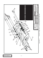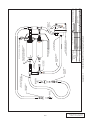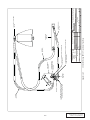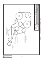
1
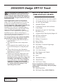
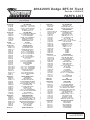
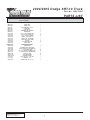
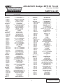
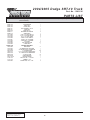
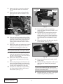
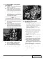
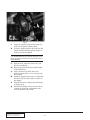
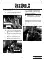
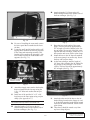
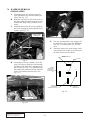
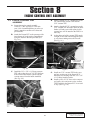
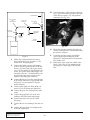
Owner Installation Manual for
PAXTON AUTOMOTIVE NOVI 2000
Supercharger Kit
for the
2004/2005 Dodge SRT-10 Truck
Paxton Automotive Corp . 1300 Beacon Place . Oxnard CA 93033
(805)604-1336 . FAX (805)604-1337
Paxton Automotive . 1300 Beacon Place . Oxnard CA 93033
(805 604-1336 . FAX (805) 604-1337
DP/N: 4809645 - v1.2 — SRT-10
01/16/06
FOREWORD
T
his manual provides information on the installation, maintenance
and service of the Paxton supercharger kit expressly designed for
the Dodge SRT-10 Truck. Contact Paxton Automotive Corporation
for any additional information regarding this kit and any of these modifications at (805) 604-1336 8:00 a.m. - 4:30 p.m. P.S.T..
An understanding of the information contained herein will help novices, as
well as experienced technicians, to correctly install and receive the greatest
possible benefit from their Paxton supercharger. When reference is made in
this manual to a brand name, number, specific tool or technique, an equivalent product may be used in place of the item mentioned. All information,
illustrations and specifications contained herein are based on the latest
product information available at the time of this publication. All rights
reserved to make changes at any time without notice.
© 2006 PAXTON AUTOMOTIVE
All rights reserved. No part of this publication may be reproduced, transmitted, transcribed,
or translated into another language in any form, by any means without written permission
of Paxton Automotive.
P/N: 4809645
©2006 Paxton Automotive
All Rights Reserved, Intl. Copr. Secured
16JAN06 v1.2 SRT-10(4809645v1.2)
ii
TABLE OF CONTENTS
FOREWARD . . . . . . . . . . . . . . . . . . . . . . . . . . . . . . . . . . . . . . . . . . . . . . . . . . . . . . . . . . . . .ii
TABLE OF CONTENTS . . . . . . . . . . . . . . . . . . . . . . . . . . . . . . . . . . . . . . . . . . . . . . . . . . .iii
RECOMMENDED TOOLS FOR INSTALLATION . . . . . . . . . . . . . . . . . . . . . . . . . . . .iv
PARTS LIST (2004/2005 Dodge SRT-10 Truck, Polished) . . . . . . . . . . . . . . . . . . . . . . . . . .v
PARTS LIST (2004/2005 Dodge SRT-10 Truck) . . . . . . . . . . . . . . . . . . . . . . . . . . . . . . . . .vii
1.
DISASSEMBLY . . . . . . . . . . . . . . . . . . . . . . . . . . . . . . . . . . . . . . . . . . . . . . .1-1
1.1
AIR INTAKE ASSEMBLY REMOVAL . . . . . . . . . . . . . . . . . . . . . . . . . . . . . .1-1
1.2
ACCESSORY BELT AND ALTERNATOR REMOVAL . . . . . . . . . . . . . . . . .1-3
1.3
CRANK PIN INSTALLATION . . . . . . . . . . . . . . . . . . . . . . . . . . . . . . . . . . . .1-3
2
OIL FEED AND ASSEMBLY . . . . . . . . . . . . . . . . . . . . . . . . . . . . . . . . . . . . .2-1
2.1
SUPERCHARGER OIL FEED INSTALLATION . . . . . . . . . . . . . . . . . . . . . .2-1
3
OIL DRAIN AND ASSEMBLY . . . . . . . . . . . . . . . . . . . . . . . . . . . . . . . . . . . .3-1
3.1
SUPERCHARGER OIL DRAIN INSTALLATION . . . . . . . . . . . . . . . . . . . . .3-1
4
SUPERCHARGER MOUNTING BRACKET ASSEMBLY . . . . . . . . . . . . . . .4-1
4.1
SUPERCHARGER MOUNTING BRACKET INSTALLATION . . . . . . . . . . .4-1
5
SUPERCHARGER ASSEMBLY INSTALLATION . . . . . . . . . . . . . . . . . . . . .5-1
5.1
SUPERCHARGER INSTALLATION . . . . . . . . . . . . . . . . . . . . . . . . . . . . . . .5-1
6
AIR INTAKE ASSEMBLY INSTALLATION . . . . . . . . . . . . . . . . . . . . . . . . .6-1
6.1
AIR INTAKE DUCT INSTALLATION . . . . . . . . . . . . . . . . . . . . . . . . . . . . . .6-1
6.2
AIR FILTER ENCLOSURE . . . . . . . . . . . . . . . . . . . . . . . . . . . . . . . . . . . . . .6-3
7.
CHARGE AIR COOLER ASSEMBLY INSTALLATION . . . . . . . . . . . . . . . . .7-1
7.1
CHARGE COOLER INSTALLATION . . . . . . . . . . . . . . . . . . . . . . . . . . . . . .7-1
7.2
WATER COOLER ASSEMBLY INSTALLATION . . . . . . . . . . . . . . . . . . . . .7-2
7.3
WATER PUMP INSTALLATION . . . . . . . . . . . . . . . . . . . . . . . . . . . . . . . . . .7-2
7.4
WATER PUMP RELAY INSTALLATION . . . . . . . . . . . . . . . . . . . . . . . . . . . .7-3
8
ENGINE CONTROL UNIT ASSEMBLY . . . . . . . . . . . . . . . . . . . . . . . . . . . .8-1
9.
FUEL PUMP FMU ASSEMBLY . . . . . . . . . . . . . . . . . . . . . . . . . . . . . . . . . . .9-1
9.1
FUEL PUMP FMU ASSEMBLY INSTALLATION . . . . . . . . . . . . . . . . . . . . .9-1
10
FINAL CHECK-0UT AND START-UP . . . . . . . . . . . . . . . . . . . . . . . . . . . . . .10-1
10.1 INSPECT THE FOLLOWING . . . . . . . . . . . . . . . . . . . . . . . . . . . . . . . . . . . .10-1
10.2 PERFORM THE FOLLOWING . . . . . . . . . . . . . . . . . . . . . . . . . . . . . . . . . . .10-1
10.3 CHECK FOR THE FOLLOWING . . . . . . . . . . . . . . . . . . . . . . . . . . . . . . . . .10-1
APPENDICES . . . . . . . . . . . . . . . . . . . . . . . . . . . . . . . . . . . . . . . . . . . . . . . . . . . . .A-1
Appendix A-2 2004/2005 Dodge SRT-10 Truck Supercharger Mounting Bracket . .A-2
Appendix A-3 2004/2005 Dodge SRT-10 Truck Auxiliary Fuel System . . . . . . . . . .A-3
Appendix A-4 2004/2005 Dodge SRT-10 Truck ECU Wiring Diagram . . . . . . . . . .A-4
Appendix A-5 2004/2005 Dodge SRT-10 Truck Water Tank/Hose . . . . . . . . . . . . . .A-5
Appendix A-6 2004/2005 Dodge SRT-10 Truck Belt Routing Diagram . . . . . . . . . .A-6
iii
P/N: 4809645
©2006 Paxton Automotive
All Rights Reserved, Intl. Copr. Secured
16JAN06 v1.2 SRT-10(4809645v1.2)
2004/2005 Dodge SRT-10 Truck
RECOMMENDED TOOLS
FOR INSTALLATION:
B
efore beginning this installation, please
read through this entire instruction booklet and the Street Supercharger System
Owner's Manual which includes the Automotive
Limited Warranties Program and the Warranty
Registration form.
Paxton supercharger systems are performance
improving devices. In most cases, increases in
torque of 30-35% and horsepower of 35-45% can
be expected with the boost levels specified by
Paxton Automotive. This product is intended for
use on healthy, well maintained engines.
Installation on a worn-out or damaged engine is
not recommended and may result in failure of the
engine as well as the supercharger. Paxton
Automotive is not responsible for engine damage.
Installation on new vehicles will not harm or
adversely affect the break-in period so long as factory break-in procedures are followed.
For best performance and continued durability,
please take note of the following key points:
1. Use only premium grade fuel 91 octane or
higher (R+M/2).
2. The engine must have stock compression
ratio.
3. If the engine has been modified in any way,
check with Paxton prior to using this product.
4. Always listen for any sign of detonation
(pinging) and discontinue hard use (no boost)
until problem is resolved.
5. Perform an oil and filter change upon completion of this installation and prior to test
driving your vehicle. Thereafter, always use a
high grade SF rated engine oil or a high quality synthetic, and change the oil and filter
every 3,000 miles or less. Never attempt to
extend the oil change interval beyond
3,000 miles, regardless of oil manufacturer's claims as potential damage to the
supercharger may result.
P/N: 4809645
©2006 Paxton Automotive
All Rights Reserved, Intl. Copr. Secured
16JAN06 v1.2 SRT-10(4809645v1.2)
1.
2.
3.
4.
5.
6.
7.
8.
9.
10.
11.
12.
13.
14.
15.
16.
17.
18.
19.
20.
21.
Factory Repair Manual
3/8" Socket and Drive Set: SAE & Metric
1/2" Socket and Drive Set: SAE & Metric
3/8" NPT Tap and Handle
Adjustable Wrench
Combination Wrench: SAE and Metric
Center Punch
Springlock 3/8" and 5/16" Fuel Fitting
Disconnect Tool
10 Quarts SH/CF Rated Quality Engine Oil
Oil Filter and Wrench
Flat #2 Screwdriver
Phillips #2 Screwdriver
Heavy Grease
Silicone Sealer
Drill Motor / Pneumatic Right Angle
1/4" Drill Bits
Stepless Clamp Pliers
3/16" Allen Wrench
Wire Strippers and Crimpers
Utility Knife
Pliers
22. Threadlocker (Blue)
23. Thread Sealant
24. Fuel Pressure Gauge
Prior to installation it will be necessary to
replace original spark plugs with spark plugs
noted below:
25. Spark Plug Socket
26. NEW Spark Plugs (NGK ZFR6F-11)
iv
2004/2005 Dodge SRT-10 Truck
Part No. 1201230-P
PARTS LIST
IMPORTANT:
PART NO.
4PCV130-026
7P125-004
7P125-005
7P125-034
7U100-055
7U250-000-220
4PCV130-036
7P375-017
7R001-008
7U030-036
7T560-001
7T 560- 002
7U100-066
21016430
1016430
4PCS037-285
4PCS111-044
4PSC010-044
4PCS010-034
4PCS017-011
7A375-166
7A375-175
7A375-250
7A375-276
7A375-278
7A375-451
7F375-017
7A375-500
7A312-525
7A312-500
7K375-030
7K312-001
2A017-010
2A017-754-04
2A017-754-05
2A017-754-03
4FU116-031
4GV016-150
4PCS116-150
2A040-011
2A047-110
8PN105-060
8N055-030
8N055-050
4PCS010-110
7P375-075
7P500-026
7R007-001
7U038-000
7U133-060
7U038-012
7A250-050
7A250-051
7E010-075
7J006-093
7U100-066
8PN106-060
8N006-010
7P500-026
7R007-001
4PCS010-010
4PCS010-020
4PCS010-030
7A250-126
7F250-021
7J006-093
8N107-150
Before beginning installation, verify that all parts are included in the kit. Report any shortages or damaged
parts immediately.
DESCRIPTION
OIL FEED ASSY
1/8"NPT 90° x -4 JIC FTG STL
1/8"NPT STR. x -4 JIC FTG STL
1/8"NPT x 1/8"NPT STRT TEE
TIE-WRAPS, 7.5" NYLON
OIL FEED HOSE, 22" -4
OIL DRAIN ASSY
3/8" x 1/2" BEADED HSE BARB FTG
# 8 STNL HOSE CLAMPS
1/2" OIL DRAIN HOSE
CUTTER, 9/16" ROTOBROACH
ARBOR, ROTOBROACH
TIE-WRAPS, 11" NYLON
SUPERCHARGER ASSY
S/C ASSY
2.85" S/C PULLEY
S/C MTG PLT ASSY
S/C MOUNTING PLATE
S/C SUPPORT PLATE
SPACER IDLER PULLEYS
STUD SPACER, SRT10
3/8-16 x 1.75" HXHD BOLTS
3/8-16 x 2.5" HXHD BOLTS
3/8-16 x 2.75" HXHD BOLTS
3/8-16 x 2.75" CSHD
3/8-16 x 4.50" HXHD BOLTS
3/8-16 NYLOCK NUT
3/8-16 x 5.0"
5/16-18 x 5.25" HXHD BOLTS
5/16-18 x 5.00" HXHD BOLTS
3/8"AN WASHERS
5/16"AN WASHERS
SPACER
1.677" x .75" x .386" SPACERS
1.543" x .75" x .386" SPACERS
1.625" x .75" x .328" SPACERS
IDLER PULLEY SMOOTH
7-RIB IDLER PULLEY
90mm SMOOTH PULLEY
IDLER PULLEY RETAINERS
GATES
WATER TANK MTG ASSY
SURGE TANK
SURGE TANK CAP
BKT MTG COOLANT RES
3/4" HOSE BARB UNION BRASS
1/2" x 3/4" BARB 90° FITTING
NYLON RATCHET CLAMP 1-1/8"
3/4" HEATER HOSE
3/4" HOSE (TANK-PUMP)
HOSE Ø3/4" x 90°
1/4-20 .75" HXHD
1/4-20 x .50" SCHDCP SCREW
12 x 3/4" SHT MTL SCREWS HXHD
6mm WASHERS
TIE-WRAPS, 11" NYLON
WATER COOLER ASSY
SINGLE PASS HT EXC
1/2" x 3/4" BARB 90° FITTINGS
NYLON RATCHET CLAMPS, 1-1/8"
HEAT EXCH MOUNTING BRKT “R”
HEAT EXCH MOUNTING BRKT “L”
HEAT EXCH BRKT SPACERS
1/4-20 x 1.25" HXHD
1/4-20 NYLOC PLT
6mm WASHERS
WATER PUMP ASSY C5
QTY.
PART NUMBER
1
1
1
1
10
1
1
1
2
1.75'
1
1
2
1
1
1
DESCRIPTION
8PN301-068
CAC, WELDED ASSY
8PN103-030
INLET DUCT, CAC
8N003-090
DISCHARGE DUCT, CAC
8N201-001
WELDED COOLER CORE
4PCS112-028
DISCHARGE ASSY
4PCS012-020/21/28
DISCHARGE DUCT T-BODY
4PCS012-041/048
DISCHARGE DUCT
4PCS010-040
CAC SUPPORT BRKT
7U250-200
TAPE, FOAM 1/4" x .250
7U038-012
HOSE Ø3/4" x 90° 4-11"
7P500-026
1/2" x 3/4" BARB 90° FTG
7P156-082
5/32" VAC TEE
7P375-250
3/8" x 3/8" x 1/4" VAC TEE
7U100-065
GROMMET .5"ID x .812"OD .187" GRV
7U030-046
5/32" VAC HOSE
8H040-175
FILTER RACE BYPASS
7PS300-200
SLEEVES, 3.00" x 2.0"L
7PS350-200
SLEEVE, 3.5" x 2.0"L
7PS400-200
SLEEVE, 4.0" x 2"L
7PS450-200
SLEEVE, 4.5" x 2"L
7R002-048
CLAMPS
7R002-056
CLAMPS
7R002-064
CLAMPS
7R002-072
CLAMPS
4PCS212-018
AIR INLET ASSY
4PCS012-011/018
CAST ELBOW MODIFIED
4PCS013-010
AIR FILTER ENCLOSURE
4PCS010-060
AIR FILTER FLANGE
4PCS110-060
A/F MOUNTING FLANGE ASSY
8H040-400
AIR FILTER
7R002-060
HOSE CLAMPS #60
7R002-064
HOSE CLAMPS #64
7U035-003
FLEX HOSE 4.0"
7A250-074
1/4-20 x 0.75" HXHD BOLTS
7F250-021
NYLOC NUTS
7J006-093
6mm WASHERS
7PS400-200
4.0" SLEEVE
7P500-001
1/2" HOSE UNION
7U030-050
1/2" FUEL HOSE (12mm)
7P375-055
3/8" x 90° x 1/2" HOSE BARB
7P375-113
PVC
7P???-???
1/2" x 3/8" REDUCER
7U030-056
3/8" PVC/VAC HOSE
5A001-071
ECU
8D204-010
RACE BYPASS ASSY
4PCV101-001
FUEL SYSTEM
5W001-005
3/8" WIRE LOOM
5W001-011
16-14 GA RING TERMINAL
5W014-030
14GA STRDWIRE BLACK
7E010-075
# 12 x 3/4" SHT METL SCRW HEX
7P312-005
5/16" FEM FUEL CNCT STEEL
7P312-007
FUEL FTG 5/16" GM x 5/16" HSE
7P312-017
5/16" HOSE BARB TO M10 x 1.0"
7P312-082
5/16" TEE HOSE BARB
7R003-027
ADEL CLAMP 1-11/16"
7R004-001
STEPLESS CLAMP 15.77.70
7U031-018
5/16" EFI FUEL HOSE
7U100-044
TIE-WRAP, 4" NYLON
7U100-055
TIE-WRAP, 7.5" NYLON
8F001-002
WALBRO IN-LINE F/P w/FTG
4PCS238-068
FMU ASSY SRT10 TRUCK
6Z001-001
DECAL PAXTON
6Z010-101
FMU HOUSING
6Z010-111
FMU VALVE BODY
6Z010-132
COVER w/SPRING
6Z020-130
SML DIAPHRAGM
6Z020-140
LG DIAPHRAGM
1
1
3
1
3
5
2
1
3
1
1
2
2
18
2
1
6
8
2
1
1
1
3
1
1
1
1
1
4
8
17'
1
1
2
1
2
5
5
1
2
2
1
1
2
5
5
16
1
v
QTY.
1
1
1
1
1
1
1'
1
1
3
1
1
15.0'
1
2
1
1
1
4
2
2
2
1
1
1
1
1
2
2
2'
4
4
8
1
1
2'
1
1
1
6"
1
1
1
6'
2
8"
4
1
1
2
4
1
22
8'
10
5
2
1
1
1
1
1
1
1
P/N: 4809645
©2006 Paxton Automotive
All Rights Reserved, Intl. Copr. Secured
16JAN06 v1.2 SRT-10(4809645v1.2)
2004/2005 Dodge SRT-10 Truck
Part No. 1201230-P
PARTS LIST
IMPORTANT:
Before beginning installation, verify that all parts are included in the kit. Report any shortages or damaged
parts immediately.
PART NO.
6Z030-150
6Z040-160
6Z050-191
6Z060-181
6Z070-030
6Z080-011
6Z090-010
7C010-050
7C010-075
7C024-025
7P125-025
7P125-031
7P125-032
7P156-082
7U030-046
7U100-030
4PCS101-010
7S625-000
7P375-072
7P375-006
5W012-000
7E010-075
5W001-037
5W001-032
5W014-030
4PCV110-010
7T100-120
7T110-125
7U250-023
DESCRIPTION
QTY.
BRKT, FMU
PISTON, FMU
FMU WASHER 8:1 PLTD
SHIM, FMU
RING, FMU 8:1
RETAINER, FMU SPRINGS
SPRING FMU
10-24 x .50" SHCS GR8 PLT
10-24 x 3/4" SHCS GR8 PLT
10-24 x .25" PHIL HEADS
1/8"NPT x 5/32" HOSE 90°
1/8"NPT x 90° 5/16" BARB
1/8"NPT SRT x 5/16" BARB
5/32" TEE
5/32" VACUUM HOSE
O-RING, FMU
SUPPORT PARTS ASSY
FIRE SLEEVE
3/8" FEMALE FUEL FTG STEEL
3/8" GM F/FTG TO 5/16" BARB FTG
12-10 GA RED WIRE
#12 x .75" SHT MTL SCREWS, HEX
12-10 INSUL BUTT CONNECTORS
1/4" SPLIT LOOM
14GA WIRE BLACK
FIXTURE w/GUIDE
DRILL BIT, #31 + .120 HSS
REAMER, .124"
DOWEL PINS, 1/8" x 1.25"L
1
1
1
1
1
2
1
6
4
3
1
1
1
2
8'
1
P/N: 4809645
©2006 Paxton Automotive
All Rights Reserved, Intl. Copr. Secured
16JAN06 v1.2 SRT-10(4809645v1.2)
4'
1
1
20'
4
2
15'
4'
1
1
1
2
vi
2004/2005 Dodge SRT-10 Truck
Part No. 1201230
PARTS LIST
IMPORTANT:
PART NO.
4PCV130-026
7P125-004
7P125-005
7P125-036
7P125-108
7U100-055
7U250-000-220
4PCV130-036
7P375-017
7R001-008
7U030-036
7T560-001
7T 560- 002
7U100-066
21016430
1016430
4PCS037-285
4PCS111-044
4PSC010-044
4PCS010-034
4PCS017-011
7A375-166
7A375-175
7A375-250
7A375-276
7A375-278
7A375-451
7F375-017
7A375-500
7A312-525
7A312-500
7K375-030
7K312-001
2A017-010
2A017-754-04
2A017-754-05
2A017-754-03
4FU116-031
4GV016-150
4PCS116-150
2A040-011
2A047-110
8PN105-060
8N055-030
8N055-050
4PCS010-110
7P375-075
7P500-026
7R007-001
7U038-000
7U133-060
7U038-012
7A250-050
7A250-051
7E010-075
7J006-093
7U100-066
8PN106-060
8N006-010
7P500-026
7R007-001
4PCS010-010
4PCS010-020
4PCS010-030
7A250-126
7F250-021
7J006-093
8N107-150
Before beginning installation, verify that all parts are included in the kit. Report any shortages or damaged
parts immediately.
DESCRIPTION
QTY.
PART NUMBER
OIL FEED ASSY
1/8"NPT 90° x -4 JIC FTG STL
1/8"NPT STR x -4 JIC FTG STL
1/8"NPT x 1/8"NPT STRT TEE
1/8"NPT x 1.5" NIPPLE
TIE-WRAPS 7.5" NYLON
OIL FEED HOSE, 22" -4
OIL DRAIN ASSY
3/8" x 1/2" BEADED HSE BARB FTG
#8 STNL HOSE CLAMPS
1/2" OIL DRAIN HOSE
CUTTER, 9/16" ROTOBROACH
ARBOR, ROTOBROACH
TIE-WRAP, 11" NYLON
SUPERCHARGER ASSY
S/C ASSY
2.85" S/C PULLEY
S/C MTG PLT ASSY
S/C MOUNTING PLATE
S/C SUPPORT PLATE
SPACER IDLER PULLEYS
STUD SPACER, SRT10
3/8-16 x 1.75" HXHD BOLTS
3/8" x 16 x 2.5" HXHD BOLTS
3/8" x 16 x 2.75" HXHD BOLTS
3/8" x 16 x 2.75" CSHD
3/8" x 16 x 4.50" HXHD BOLTS
3/8-16 NYLOCK NUT
3/8-16 x 5.00" HXHD BOLT
5/16" x 18 x 5.25" HXHD BOLTS
5/16-18 x 5.0" HXHD BOLT
3/8"AN WASHERS
5/16"AN WASHERS
SPACER
1.677" x .75" x .386" SPACERS
1.543" x .75" x .386" SPACERS
1.625" x .75" x .328" SPACERS
IDLER PULLEY SMOOTH
7-RIB IDLER PULLEY
90mm SMOOTH PULLEY
IDLER PULLEY RETAINERS
GATES 8PK2800 BELT
WATER TANK MTG ASSY
SURGE TANK
SURGE TANK CAP
BKT MTG COOLANT RES
3/4" HOSE-BARB UNION, BRASS
1/2" x 3/4"BARB x 90° FITTINGS
NYLON RATCHET CLAMPS 1-1/8"
3/4" HEATER HOSE
3/4" HOSE (TANK-PUMP)
HOSE Ø3/4" x 90°
1/4-20 .75" HXHD
1/4-20 x .50" SCHDCP SCREW
12 x 3/4" SHT-MTL SCREWS HXHD
6mm WASHERS
TIE-WRAPS, 11" NYLON
WATER COOLER ASSY
SINGLE PASS HT EXC
1/2" x 3/4" BARB 90° FITTINGS
NYLON RATCHET CLAMPS 1-1/8"
HEAT EXCH MOUNTING BRKT “R”
HEAT EXCH MOUNTING BRKT “L”
HEAT EXCH BRKT SPACERS
1/4-20 x 1.25" HXHD
1/4-20 NYLOC PLT
6mm WASHERS
WATER PUMP ASSY C5
1
1
1
1
1
10
1
1
1
2
1.75
1
1
8PN301-060
CAC, WELDED ASSY
8PN103-030
INLET DUCT, CAC
8N003-090
DISCHARGE DUCT, CAC
8N201-001
WELDED COOLER CORE
4PCS112-020
DISCHARGE ASSY
4PCS012-020/21/28
DISCHARGE DUCT T-BODY
4PCS012-041/048
DISCHARGE DUCT
4PCS010-040
CAC SUPPORT BRKT
7U250-200
TAPE, FOAM 1/4" x .250"
7U038-012
HOSE Ø3/4" x 90° 4-11"
7P500-026
1/2" x 3/4" BARB 90° FTG
7P156-082
5/32" VAC TEE
7P375-250
3/8" x 3/8" x 1/4" VAC TEE
7U100-065
GROMMET .5"ID x .812"OD .187" GRV
7U030-046
5/32" VAC HOSE
8H040-175
FILTER RACE BYPASS
7PS300-200
SLEEVES 3.0" x 2.0"L
7PS350-200
SLEEVE 3.5" x 2.0"L
7PS400-200
SLEEVE 4.0" x 2"L
7PS450-200
SLEEVE 4.5" x 2"L
7R002-052
CLAMPS
7R002-056
CLAMPS
7R002-064
CLAMPS
7R002-072
CLAMPS
4PCS212-010
AIR INLET ASSY
4PCS012-011/018
CAST ELBOW MODIFIED
4PCS013-010
AIR FILTER ENCLOSURE
4PCS010-060
AIR FILTER FLANGE
4PCS110-060
A/F MOUNTING FLANGE ASSY
8H040-400
AIR FILTER
7R002-060
HOSE CLAMPS # 60
7R002-064
HOSE CLAMPS # 64
7U035-003
FLEX HOSE 4.0"
7A250-126
1/4" x 20 x 1.0" HXHD BOLTS
7F250-021
NYLOC NUTS
7J006-093
6mm WASHERS
7PS400-200
4.0" SLEEVE
7P500-001
1/2" HOSE UNION
7U030-050
1/2" FUEL HOSE (12mm)
7P375-055
3/8" x 90° x 1/2" HOSE BARB
7P375-113
PVC
7P500-003
1/2" x 3/8" REDUCER
7U030-056
3/8" PVC/VAC HOSE
5A001-071(-070)
ECU
8D204-010
RACE BYPASS ASSY
4PCV101-001
FUEL SYSTEM
5W001-005
3/8" WIRE LOOM
5W001-011
16-14GA RING TERMINALS
5W014-030
14GA STRDWIRE BLACK
7E010-075
#12 x 3/4" SHT METL SCRW HEX
7P312-005
5/16" FEM FUEL CNCT STEEL
7P312-007
FUEL FTG 5/16" GM x 5/16" HSE
7P312-017
5/16" HOSE BARBS TO M10 x 1.0"
7P312-082
5/16" TEE HOSE BARBS
7R003-027
ADEL CLAMP 1-11/16"
7R004-001
STEPLESS CLAMPS, 15.77.70
7U031-018
5/16" EFI FUEL HOSE
7U100-044
TIE-WRAPS, 4" NYLON
7U100-055
TIE-WRAPS, 7.5" NYLON
8F001-002
WALBRO INLINE F/P w/FTGS
4PCS238-068
FMU ASSY SRT10 TRUCK
6Z001-001
DECAL PAXTON
6Z010-101
FMU HOUSING
6Z010-111
FMU VALVE BODY
6Z010-132
COVER w/SPRING
6Z020-130
SML DIAPHRAGM
1
1
1
1
1
3
1
3
5
2
1
3
1
1
2
2
18
2
1
6
8
2
1
1
1
3
1
1
1
1
1
4
8
17'
1
1
2
1
2
5
5
1
2
2
1
1
2
5
5
16
1
vii
DESCRIPTION
QTY.
1
1
1
1
1
1
1'
1
1
3
1
1
15.0'
1
2
1
1
1
4
2
2
2
1
1
1
1
1
2
2
2'
4
4
8
1
1
2'
1
1
1
6"
1
1
1
6'
2
8"
4
1
1
2
4
1
22
8'
10
5
2
1
1
1
1
1
1
P/N: 4809645
©2006 Paxton Automotive
All Rights Reserved, Intl. Copr. Secured
16JAN06 v1.2 SRT-10(4809645v1.2)
2004/2005 Dodge SRT-10 Truck
Part No. 1201230
PARTS LIST
IMPORTANT:
Before beginning installation, verify that all parts are included in the kit. Report any shortages or damaged
parts immediately.
PART NO.
6Z020-140
6Z030-150
6Z040-160
6Z050-191
6Z060-181
6Z070-030
6Z080-011
6Z090-010
7C010-050
7C010-075
7C024-025
7P125-025
7P125-031
7P125-032
7P156-082
7U030-046
7U100-030
4PCS101-010
7S625-000
7P375-072
7P375-006
5W012-000
7E010-075
5W001-037
5W001-032
5W014-030
4PCV110-010
7T100-120
7T110-125
7U250-023
DESCRIPTION
QTY.
LG DIAPHRAGM
BRKT, FMU
PISTON, FMU
FMU WASHER 8:1 PLTD
SHIM, FMU
RING, FMU 8:1
RETAINER, FMU SPRING
SPRING FMU
10-24 x .50" SHCS GR8 PLT
10-24 x .3/4" SHCS GR8 PLT
10-24 x .25" PHIL HEADS
1/8"NPT x 5/32" HOSE 90°
1/8"NPT - 90° 5/16" BARB
1/8"NPT SRT - 5/16" BARB
5/32" TEES
5/32" VACUUM HOSE
O-RING, FMU
SUPPORT PARTS ASSY
FIRE SLEEVE
3/8" FEMALE FUEL FTG STEEL
3/8" GM F/FTG TO 5/16" BARB FTG
12-10 GA RED WIRE
#12 x .75" SHT MTL SCREWS HEX
12-10 INSUL BUTT CONNECTORS
1/4" SPLIT LOOM
14GA WIRE BLACK
FIXTURE w/GUIDE
DRILL BIT, #31 + .120 HSS
REAMER, .124"
DOWEL PINS, 1/8" x 1.25"L
1
1
1
1
1
1
2
1
6
4
3
1
1
1
2
8'
1
P/N: 4809645
©2006 Paxton Automotive
All Rights Reserved, Intl. Copr. Secured
16JAN06 v1.2 SRT-10(4809645v1.2))
4'
1
1
20'
4
2
15'
4'
1
1
1
2
viii
Section 1
DISASSEMBLY
C. After removing the air inlet duct, remove the
two spring clips retaining the air filter cover
housing. Remove the air filter from the
housing. (See Fig. 1-c.)
1.1 AIR INTAKE ASSEMBLY REMOVAL
(Please note that before any work is performed,
disconnect the battery positive and negative terminals)
Before beginning installation, replace all
spark plugs with NGKZFR6F-11 (follow
the procedures indicated within the factory
repair manual and/or as indicated on the factory underhood emissions tag). Do not use
platinum spark plugs. Change spark plugs
at least every 15,000 miles and spark plug
wires at least every 50,000 miles.
CLIPS
A. Using a 5/16" nut driver or a flat blade
screw driver, loosen the hose clamp securing
the inlet duct to the throttle body. (See Fig.
1-a.)
Fig. 1-c
D. Remove the small clip retaining the crank
case breather hose to the upper air filter
housing and remove the hose. (See Fig.
1-d.)
QUAD CAB ON 2005
MODELS MAY BE
DIFFERENT
BREATHER HOSE
Fig. 1-a
B. Locate the intake air temp sensor on the side
of the intake air duct and remove the plug.
(See Fig. 1-b.)
Fig. 1-d
E.
IAT SENSOR
Remove the rubber inlet duct from the throttle body. Lift the duct and upper portion of
the air-filter cover out of the vehicle and set
aside. It will not be reused.
Fig. 1-b
1-1
P/N: 4809645
©2006 Paxton Automotive
All Rights Reserved, Intl. Copr. Secured
16JAN06 v1.2 SRT-10(4809645v1.2)
Remove the idle air control hose from the
IAC. Set the hose aside as it will not be
reused.
G. Remove the one 10mm nut located at the
front of the lower air box enclosure. (See
Fig. 1-e.)
F.
10mm HEADED
BOLT
13mm HEADED
BOLTS
INNER FENDER
FRAME-REAR
Fig. 1-f
10mm NUT
N. From inside the engine compartment,
remove the battery box and set aside. It will
not be reused.
O. In preparation for removing the plastic air
deflector shield that attaches to the inner
fender, remove the two 13mm headed bolts
securing the engine oil cooler in place. Set
the cooler aside to be reinstalled in a later
step.
P. Remove the plastic clips that retain the plastic air deflector. (See Fig. 1-g.)
Fig. 1-e
H. Lift up on the lower portion of the air filter
enclosure removing it from the rubber grommets that secure the back portion of the air
filter enclosure. Once removed from the
vehicle, set the enclosure aside. It will not
be reused.
I. Remove the crank case breather hose located
under the throttle body and set aside to be
modified and reinstalled in a later step.
*** NOTE ***
2005 6-speed and Quad Cab trucks may be different.
Remove the four 13mm headed bolts that
secure the top portion of the extra battery
box and set aside as they will not be reused.
(See Fig. 1-f for location.)
K. Remove the 10mm bolt that secures the
heater hoses to the battery box. (See Fig.
1-f.)
L. Remove the passenger’s side front tire and
remove the 8mm headed screw that retains
the inner fender liner. Remove the liner and
set aside to be reinstalled in a later step.
M. Locate the two bolts that secure the battery
box from inside the fender well. Remove
and set aside. (See Fig. 1-f.)
J.
Fig. 1-g
Q. Remove the deflector and set aside, it will
not be reused.
R. Reinstall the inner fender liner in the reverse
order removed. Reinstall the passenger’s
side tire.
*** NOTE ***
Two of the 8mm headed bolts that secure the inner
fender liner will not be reinstalled. Their location was in
the bottom of the battery cover.
S.
P/N: 4809645
©2006 Paxton Automotive
All Rights Reserved, Intl. Copr. Secured
16JAN06 v1.2 SRT-10(4809645v1.2))
1-2
Reinstall the factory oil cooler in its original
location using the factory hardware.
1.2 ACCESSORY BELT AND ALTERNATOR REMOVAL
A. Locate the factory belt tensioner on the passenger side of the vehicle.
B. Using a 15mm box end wrench, rotate the
tensioner counter clockwise to release the
accessory belt. Once the belt has been loosened, remove the belt from the vehicle. It
will not be reused.
C. Locate and remove the 9/16" headed bolt
retaining the top of the alternator. Remove
the 5/8" headed bolt and nut that secures the
lower mount of the alternator.
REMOVE BOLTS
*** NOTE ***
If you have not already disconnected the Positive and
the Negative battery cables you should do so now.
Fig. 1-i
D. Remove the electrical connectors from the
alternator to be reinstalled at a later stage of
the installation.
E. Remove the alternator. It may be necessary
to move the alternator toward the front of
the vehicle to release the bushing located in
the lower alternator mounting boss. Remove
the alternator and set aside to be reinstalled
in a later step. (See Fig. 1-h.)
1.3 CRANK PIN INSTALLATION
PLEASE NOTE: Because there is not a keyway
securing the crank pulley from the factory,
there is the possibility of the crank pulley
spinning on the crankshaft. This section will
guide you throught the procedure of
installing dowel pins to secure the crank
pulley to the crankshaft.
A. Remove the lines from the power steering
pump. These are the lines that drive the fan.
B. It has been found that a crow-foot type
wrench works best. But other types of
wrenches may work as well.
C. Drain the engine coolant into a suitable container.
D. Remove the upper and lower radiator hoses
from the radiator.
E. Remove the two 10mm headed bolts that
secure the radiator to the front core support.
F. Remove the nylon clips that retain the wire
leading to the connector on the fan motor.
Remove the nylon clips retaining the wire to
the fan motor.
G. Remove the radiator and fan assembly from
the truck and set aside.
H. Remove the bolts that retain the crank pulley
to the factory harmonic damper.
I. Remove the factory bolt that secures the
damper. (See Fig. 1-j.)
Fig. 1-h
Remove the factory idler pulley and set
aside to be reinstalled in a later step.
G. With the alternator removed and set aside,
remove the two 1/2"-headed bolts located
next to the alternator. Set these bolts asidethey will not be reused. (See Fig. 1-i.)
F.
1-3
P/N: 4809645
©2006 Paxton Automotive
All Rights Reserved, Intl. Copr. Secured
16JAN06 v1.2 SRT-10(4809645v1.2)
Fig.1-j
Install the supplied guide fixture using two
of the factory pulley retaining bolts.
K. Using the supplied drill bit and with the drill
fixture installed drill through the damper in
to the end of the crankshaft.
J.
*** NOTE ***
It is recommended that you measure the length of the
dowel pin and the drill fixture and mark the drill bit for
quick reference.
L.
M.
N.
O.
P.
Q.
Drill one hole, rotate the fixture 180° and
drill the second hole.
Remove the drill fixture and confirm depth
of the drilled hole.
After both dowel pin holes have been
drilled, ream the holes to size using the supplied reamer.
Install the supplied dowel pins. Confirm that
the dowel pins are flush with the surface of
the damper.
Reinstall the factory damper bolt and torque
to factory specs.
Reinstall the radiator in the reverse order of
its removal. Install the coolant hoses and
refill the radiator with coolant.
P/N: 4809645
©2006 Paxton Automotive
All Rights Reserved, Intl. Copr. Secured
16JAN06 v1.2 SRT-10(4809645v1.2))
1-4
Section 2
OIL FEED AND ASSEMBLY
2.1 SUPERCHARGER OIL FEED
INSTALLATION
*** NOTE ***
It is not recommended to use anything other than
engine oil on the threads. If Teflon paste or tape is
used, a piece could be dislodged and pass through the
oil feed jet clogging the oil feed jet. This will cause
severe damage to the supercharger.
A. Locate the oil-sending unit on the passenger’s side of the vehicle. Remove the sending unit connector. (See Fig. 2-a.)
E.
Install the straight 1/8" x –4 JIC fitting (supplied in assembly 4PCS130-026) into the
outlet facing toward the top of the engine.
*** NOTE ***
It maybe easier to install this fitting from the top of the
engine compartment. With the alternator out of the way
it is a straight shot to the top of the fitting installed in
an earlier step.
F.
OIL SENDING UNIT
CONNECTOR
Re-Install the Factory oil-sending unit. (See
Fig. 2-c.)
Fig. 2-a
B. Using a 1-1/8" socket, remove the sending
unit and set aside to be reinstalled in a later
step.
C. Locate the nylon-retaining clip located just
above the factory-sending unit that secures
the factory oil sending sensor wire. This clip
will have to be removed to gain clearance
for the 1/8" x –4 fitting. (See Fig. 2-b.)
D. Install the street TEE in the same location as
the factory-sending unit. (See Fig. 2-b.)
Fig. 2-c
NYLON RETAINING CLIP
TO BE REMOVED
Fig. 2-b
2-1
P/N: 4809645
©2006 Paxton Automotive
All Rights Reserved, Intl. Copr. Secured
16JAN06 v1.2 SRT-10(4809645v1.2)
G. Locate the supplied 22" long stainless steel
braided oil feed line and attach it to the fitting that was installed in Step E. (See
Fig. 2-d.)
Fig. 2-d
P/N: 4809645
©2006 Paxton Automotive
All Rights Reserved, Intl. Copr. Secured
16JAN06 v1.2 SRT-10(4809645v1.2))
2-2
Section 3
OIL DRAIN AND ASSEMBLY
3.1 SUPERCHARGER OIL DRAIN
INSTALLATION.
A. Locate the oil drain assembly 4PCV130-036
that is supplied in the supercharger kit
B. Locate the supplied 9/16" Rotobroach and
arbor. You will need a 3/8" electric or air
drill motor for this procedure.
C. Because the supercharger is oil fed, it
requires a provision for drainage. On the
passenger’s side of the vehicle there is a
small pad machined on the rail of the oil
pan. Just below this pad will be the location
for the oil drain fitting. (See Fig. 3-a.)
Fig. 3-b
G. Thread the hole using a 3/8"-18 NPT tap
(not provided). Make sure that the threads
are square to the face of the oil pan mounting surface. Do not thread any deeper than
half the length of the tap.
H. Locate the 3/8" x 1/2" barbed NPT fitting
that is supplied in the oil drain assembly.
Use some form of sealant such as RTV silicone to seal the threads and tighten the fitting into place. (See Fig. 3-c.)
Fig. 3-a
D. Measure down from the center of this
machined pad 3/4" and put a scribe mark.
This will be the location that will be drilled
and tapped for the oil drain fitting.
E. Drill a 3/16" pilot hole for the Rotobroach
this is necessary to keep the small piece that
is cut by the Rotobroach from falling into
the oil pan.
F. Using the Rotobroach that is supplied, slowly drill into the cast oil pan. Be careful not
to drop the small piece of aluminum into the
pan once you have gone all the way through.
(See Fig. 3-b.)
Fig. 3-c
3-1
P/N: 4809645
©2006 Paxton Automotive
All Rights Reserved, Intl. Copr. Secured
16JAN06 v1.2 SRT-10(4809645v1.2)
This Page Left Intentionally Blank
P/N: 4809645
©2006 Paxton Automotive
All Rights Reserved, Intl. Copr. Secured
16JAN06 v1.2 SRT-10(4809645v1.2))
3-2
Section 4
SUPERCHARGER MOUNTING BRACKET ASSEMBLY
4-1. SUPERCHARGER MOUNTING
BRACKET INSTALLATION
A. Remove the factory idler from the tensioner
and replace with the supplied large-diameter
idler using the factory hardware.
B. Please refer to the mounting bracket assembly 4PCS111-044 parts list in the front of
this manual to confirm that you have the
correct mounting hardware. Also see assembly drawing 4PCS111-044 (Appendix “A”)
for bolt and spacer locations.
C. In preparation for the supercharger mounting
plate to be installed, you will need to reinstall the alternator previously removed.
D. When installing the alternator you will not
be reusing the factory fasteners.
E. Locate the large 1/2" thick aluminum
mounting plate in the supercharger mounting
plate assembly, and the appropriate mounting hardware. (See Fig. 4-a.)
Fig. 4-b
*** NOTE ***
It has been found that some vehicles have different
depth holes. We provide 2-5/16-18 x 5.00" bolts in this
case.
G. Install the supercharger mounting plate with
the two 5/16-18 x 5.25" bolts, washers and
spacers as an assembly.
H. Insert the 3/8-16 x 5.00" long bolt with
washer through the mounting bracket and
lower alternator mounting hole. Secure with
a 3/8" washer and Nyloc nut. (See Fig. 4-c.)
3/4" x 5.00 BOLT
Fig. 4-a
*** NOTE ***
For ease of installation, all of the supercharger mounting plate bolts will be left loose until later in the installation of the mounting bracket.
F.
Locate the two 5/16-18 x 5.25" inch long
bolts and two 5/16"AN washers along with
two Ø1.625" x Ø.75" x .328" spacers. Install
the bolts, washers and spacers at the location
noted. (See Fig. 4-b.)
Fig. 4-c
4-1
P/N: 4809645
©2006 Paxton Automotive
All Rights Reserved, Intl. Copr. Secured
16JAN06 v1.2 SRT-10(4809645v1.2)
I.
Locate the .335" x 1.0" x .484" spacer and
the 3/8" x 16 x 2.75" bolt and 3/8"AN flat
washer. Install the spacer and the bolt in the
upper alternator mounting location. (See
Fig. 4-d.)
L.
*** NOTE ***
The spacer goes between the supercharger mounting
plate and the alternator. (See Fig. 4-d.)
Locate the three supplied accessory idler pulleys with their proper spacers and two 3/8" x
16 x 1.75" bolts and washers. Install the
smooth 90mm idler at the 3/8"-16 tapped hole
location next to the alternator. Install the plastic 7-rib grooved idler just above the smooth
idler using the provided fasteners. (See Fig.
4-f.) See assembly drawing 4PCS111-044 in
Appendix A for these locations.
*** NOTE ***
In Fig. 4-f, the upper A/C line will have to be removed
from its original location to gain clearance for the S/C
mounting plate.
SPACER
Fig. 4-d
With the supercharger mounting plate, spacers and bolts installed, start tightening the
1/2" headed bolt going into the front cover
of the engine. Next tighten the lower alternator through-bolt and then the upper alternator bolt.
K. Reinstall the factory idler pulley using the
stud spacer provided in place of the factory
retaining bolt. (See Fig. 4-e.)
J.
Fig. 4-f
M. Locate the supercharger support plate with
the seven 1.543" x .390" x Ø.750" spacers
and its mounting hardware.
N. Install the support plate over the stud bolt
that was installed in the factory idler location using the 3/8" –16 nyloc nut and washer
leave these fasteners loose until all of the
spacers and bolts are installed.
O. Please check the mounting hardware against
the bill of materials in the front of the manual for the lengths and quantities.
P. Install the 6-1.543" long spacer between the
supercharger support plate and the supercharger mounting plate with the bolts provided.
Q. There are three bolts that are 2.5" in length.
One will be located just above the alternator
and the other two are installed between the
supercharger mounting holes and the alternator.
*** NOTE ***
The photo shows the Factory fastener for reference
and will not be reused. (See Fig. 4-e.)
FACTORY SCREW
(DO NOT RE-USE)
Fig. 4-e
P/N: 4809645
©2006 Paxton Automotive
All Rights Reserved, Intl. Copr. Secured
16JAN06 v1.2 SRT-10(4809645v1.2))
4-2
Section 5
SUPERCHARGER ASSEMBLY INSTALLATION
5.1 SUPERCHARGER INSTALLATION
SUPERCHARGER
MOUNTING BOLT HOLES
A. Attach the 1/2" oil drain hose to the supercharger using the hose provided and one #8
hose clamp.
B. Lower the supercharger into place. Guide
the oil drain hose so there are no kinks or
dips in the hose.
C. Loosely install the 3/8-16 counter-sunk bolt
in the supercharger mounting plate (located
just below the tapped hole). Install this spacer between the supercharger and the plate.
*** NOTE ***
This bolt must be installed before the Idler pulley is
installed. (See Fig. 5-a.)
Fig. 5-b
When all of the supercharger mounting bolts
are installed, evenly tighten all supercharger
mounting bolts.
F. Using one #8 hose clamp, attach the oil
drain hose to the 1/2" barbed fitting that was
installed in Section 3 (oil drain installation).
G. Install the 90° x 1/4" x –4 fitting into the
supercharger oil feed jet. Use only oil on
this fitting rather then teflon paste or teflon
tape. Either of which may become dislodged
and enter the jet clogging the small orifice
of the oil feed jet. Attach the 22" long –4
stainless steel braided hose installed in an
earlier step. (See Fig. 5-c.)
E.
COUNTER SUNK
BOLT LOCATION
Fig. 5-a
D. Install the two supercharger mounting bolts
with their spacers in the outer most mounting holes of the supercharger mounting
plate. Loosely tighten these bolts. (See Fig.
5-b.)
Fig. 5-c
5-1
P/N: 4809645
©2006 Paxton Automotive
All Rights Reserved, Intl. Copr. Secured
16JAN06 v1.2 SRT-10(4809645v1.2)
This Page Left Intentionally Blank
P/N: 4809645
©2006 Paxton Automotive
All Rights Reserved, Intl. Copr. Secured
16JAN06 v1.2 SRT-10(4809645v1.2))
5-2
Section 6
AIR INTAKE ASSEMBLY INSTALLATION
6.1 AIR INTAKE DUCT INSTALLATION
A. Locate air intake assembly 4PCS212-010
(4PCS212-018 if polished).
B. Install the 4" sleeve and two #64 hose
clamps to the inlet of the supercharger leaving the clamps loose. They will be tightened
in a later step.
C. Locate the 4" cast duct and 3/8"NPT x 1/2"
x 90° barbed fitting.
D. Install the fitting into the cast duct using a
small amount of teflon sealant. (See Fig.
6-a.)
Fig. 6-b
G. Attach a length of 1/2" fuel hose to the
barbed fitting and route towards the crank
case vent hose located at the front of the
engine. (This vent hose was previously
removed in the disassembly of the factory
air intake system.) (See Fig. 6-c.)
Fig. 6-a
E
F.
Install the cast duct into the 4" sleeve previously installed to the inlet of the supercharger.
Orient the barbed fitting so it points to the
passenger’s side valve cover. (See Fig. 6–b.)
THIS PORTION WILL
NOT BE RE-USED
Fig. 6-c
6-1
P/N: 4809645
©2006 Paxton Automotive
All Rights Reserved, Intl. Copr. Secured
16JAN06 v1.2 SRT-10(4809645v1.2)
H. 2004 Model 6-Speed: This hose needs
to be oriented in reverse of the factory orientation. Install the 1/2" hose union into the
end of the hose previously installed to the
1/2" barbed fitting in the 4" cast duct. Attach
the hose union to the factory vent hose. (See
Fig. 6-d.)
FACTORY
BREATHER HOSE
TO VALVE
COVER
Fig. 6-f
Fig. 6-d
I.
K. Install the PCV valve in the location of the
factory breather on the passenger’s side of
the vehicle. (See Fig. 6-g.)
Locate the small rubber 90º fitting on the
passenger’s side valve cover. Remove the
fitting and set aside as it will not be reused.
(See Fig. 6-e.)
Fig. 6-g
Fig. 6-e
J
L.
Assemble the new PCV valve assembly (See
Fig. 6-f.)
P/N: 4809645
©2006 Paxton Automotive
All Rights Reserved, Intl. Copr. Secured
16JAN06 v1.2 SRT-10(4809645v1.2))
6-2
Connect the PCV valve to the factory hard
plastic line.
M. 2005 6-Speed Quad Cab: The PCV
valve will be installed at the front of the driver’s side valve cover. You will need to
remove the factory crank case breather hose
from under the throttle body. Modify the
hose to fit with the parts supplied. (See Fig.
6-h.)
N. Assemble the crank case breather assembly
as seen. (See Figs. 6-j, 6-k.)
S/C AIR INLET
FITTING
FACTORY, VALVE
COVER FITTING
FACTORY 90 ELBOW
ATTACHEDTO THE DRIVER’S
SIDE VALVE COVER
Fig. 6-j
Fig. 6-h
Fig. 6-k
Fig. 6-i
6-3
P/N: 4809645
©2006 Paxton Automotive
All Rights Reserved, Intl. Copr. Secured
16JAN06 v1.2 SRT-10(4809645v1.2)
6.2 AIR FILTER ENCLOSURE
A. In assembly 4PCS212-020 (or 4PCS212-028
if you have purchased a polished kit).
Locate the air filter, air-filter enclosure, nuts,
bolts and air-filter flange.
B. Attach the air filter flange to the formed air
filter enclosure with the fasteners that are
provided in the assembly. Secure the air filter to the flange.
C. Have the filter enclosure as far forward as
possible when mounting it to the passenger’s
side fender well. Mark and drill the holes.
Use the supplied sheet metal screws. Make
sure nothing is rubbing on the filter enclosure.
D Secure the air-filter enclosure with the provided self tapping fasteners. (See Figs. 6-l,
6-m.)
Fig. 6-l
Fig. 6-m
E.
Attach the supplied flex hose to the air filter
and the 4" cast inlet duct with the hose
clamps that are provided.
P/N: 4809645
©2006 Paxton Automotive
All Rights Reserved, Intl. Copr. Secured
16JAN06 v1.2 SRT-10(4809645v1.2))
6-4
Section 7
CHARGE AIR COOLER ASSEMBLY INSTALLATION
7.1 CHARGE AIR COOLER
INSTALLATION
bypass valve. You will need to move the
A.C. line to gain clearance for the charge
cooler bypass valve.
A. Locate the Charge Air Cooler. Install the 90°
x 1/2"NPT x 3/4" barbed fittings in the
charge cooler. Use teflon paste on these fittings to prevent leakage. (See Fig. 7-a.)
Fig. 7-c
Install the charge cooler to the discharge of
the supercharger. Tighten the hose clamps.
G. Install the discharge duct “A” (Viper Head)
to the Charge Air Cooler outlet and secure
with the hose clamp previously installed.
H. Attach the 4.5" sleeve to the throttle body.
Using two #67 clamps, secure the discharge
tube “B” onto the throttle body. Install the
factory air intake temperature sensor into
discharge tube “B”.
I. Check discharge ducts for proper fitment
and recheck all hose clamps.
F.
Fig. 7-a
B. Locate the charge air support bracket and
install it on two of the exhaust shield mounting bolts. Install the supplied foam padding
onto the support bracket. (See Fig. 7-b.)
Fig. 7-b
C. Install the 3" silicone sleeves and clamps to
the inlet and discharge of the charge air
cooler.
D. Install the compressor bypass valve with the
gasket and fastener provided (See Fig. 7-c.)
E. Install the compressor bypass filter to the
Fig. 7-d
7-1
P/N: 4809645
©2006 Paxton Automotive
All Rights Reserved, Intl. Copr. Secured
16JAN06 v1.2 SRT-10(4809645v1.2)
J.
7.3 WATER PUMP INSTALLATION
You will need to mark/drill in the brackets
that are in front of A.C.. Use the 1/4-20
bolts/nylock.
A. Locate the water pump assembly. The water
pump will be attached to the triangular
shaped water tank supplied in the kit.
B. Attach the water pump to the reservoir using
one 1-1/8" insulated clamp and a 1/4-20 x
1/2" socket head bolt and one 1/4"AN washer. (See Fig. 7-g.)
C. Attach the Ø3/4" x 4 x 12" “L” shaped hose
to the 1/2"NPT x 3/4" x 90º barbed fitting
located at the bottom of the triangle water
reservoir (NOTE the 90º hose attached to
the water pump and the fitting at the bottom
of the water tank will need to be trimmed to
fit) and secure with the provided nylon
clamps. (See Figs. 7-f, 7-g.)
7.2 WATER COOLER ASSEMBLY
INSTALLATION.
A. Attach the right and the left heat exchanger
bracket to the heat exchanger using the 1/420 x 1-1/4" bolts, nuts and washers provided
in the heat exchanger assembly.
B. Install the two 90º x 1/2"NPT x 3/4" fittings
into the heat exchanger using teflon paste on
the threads. These fittings, when installed,
should face the passenger’s side of the vehicle.
C. Attach the heat exchanger to the front of the
air conditioning condenser mounting brackets using the fasteners that are provided.
(See Figs. 7–e, 7-f.)
*** NOTE ***
The angled bracket that is attached to the water tank is
in place just to show its orientation to the water pump.
This bracket will be installed in a later step of the
installation.
*** NOTE ***
After the installation of the hoses from the heat
exchanger to the CAC and the water reservoir, the air
deflectors on the hood will need to be trimmed for
clearance.
Fig. 7-g
Fig. 7-e
Fig. 7-f
P/N: 4809645
©2006 Paxton Automotive
All Rights Reserved, Intl. Copr. Secured
16JAN06 v1.2 SRT-10(4809645v1.2))
7-2
H. Attach a length of 3/4" hose to the 90º
barbed fitting located on the farthest side of
the heat exchanger. (See Fig. 7-j.)
Fig. 7-h
Fig. 7-j
D. For ease of installing the water tank, remove
the lower panel that is attached to the front
air dam.
E. Locate the small angled bracket and the selftapping sheet metal screws that are provided
in the water tank mounting assembly. This
bracket will be attach to the passenger’s side
inner fender between the front radiator core
supports. (See Fig. 7-i.)
Route the hose to the outlet of the water
pump. This hose should be approximately
42" in length. (Check its fitment before cutting to length.) In one end of the hose coming from the heat exchanger, install one 3/4"
hose mender and secure with a nylon clamp.
J. Install the hose to the 90º that was attached
to the water pump in an earlier step. Secure
the hose with a nylon clamp.
K. At the heat exchanger, attach a length of
3/4" hose with a clamp to the 90º barbed fitting closest to the passenger’s side of the
vehicle. This hose should be approximately
86" in length. (See Fig. 7-k.)
I.
WATER TANK MOUNTING
BRACKET LOCATION
Fig. 7-i
Attach the triangle water tank to the bracket
that was installed in the last step using the
1/4" x 1/2" bolts and washers that are provided.
G. Install one of the provided 4" x 12" x 90º
long hoses to the water pump using a nylon
clamp. (See Appendix A-5.)
F.
Fig. 7-k
Attach the other end of the hose to the 90º
barbed fitting located on the charge air cooler. It should be attached to the fitting located
closest to the intake manifold. Secure with a
nylon clamp.
M. These hoses should be routed away from
any hot or sharp objects.
L.
*** NOTE ***
This formed hose may need to be trimmed to fit.
H. Attach a length of 3/4" hose to the 90º
barbed fitting located on the farthest side of
the heat exchanger. (See Fig. 7-j.)
7-3
P/N: 4809645
©2006 Paxton Automotive
All Rights Reserved, Intl. Copr. Secured
16JAN06 v1.2 SRT-10(4809645v1.2)
7.4 WATER PUMP RELAY
INSTALLATION
A. Locate the group of wires next to the fire
wall. Attach the relay with the fastener provided. (See Fig. 7-l.)
B. Route the long red wire #87 on the relay to
the water pump and attach to the green wire
with the blue stripe using a solderless connector.
C. Attach the black wire #85 (relay ground) to
the screw securing the factory ground wires
in place. (See Fig. 7-l.)
FACTORY WATER
PUMP RELAY
Fig. 7-n
E.
FACTORY GROUND
F.
The wire at terminal #86 (relay trigger) will
be attached in a later step of the installation.
(See Fig. 7-o and Appendix A-4. for reference)
Attach the ground wire at the charge cooler
water pump to one of the screws that retain
the water reservoir to the chassis.
POWER TO WATER PUMP
(RED WIRE)
NOT USED
Fig. 7-l
87
D. Locate the red wire at terminal # 30 on the
relay (12V power). Route this wire through
the factory wire loom that is running across
the fire wall. (See Fig. 7-m.) Attach the fuse
link with a butt connector and ring terminal
to the 12V terminal at the fuse box. (See
Fig. 7-n.)
TRIGGER
(FROM FACTORY
ECU PIN) #2 PINK
& GREY WIRE ON
ECU
85
87A
30
86
GROUND
(TOFACTORY
GROUND SCREW )
POWER SUPPLY
(RED WIRE FROM
TERMINAL ON FUSE BOX)
Fig. 7-o
FACTORY WIRE LOOM
Fig. 7-m
P/N: 4809645
©2006 Paxton Automotive
All Rights Reserved, Intl. Copr. Secured
16JAN06 v1.2 SRT-10(4809645v1.2))
7-4
Section 8
ENGINE CONTROL UNIT ASSEMBLY
8.1 ENGINE CONTROL UNIT
ASSEMBLY
D. Attach a length of 5/32" vacuum hose to the
1/4" outlet of the vacuum TEE and one
5/32" vacuum TEE.
E. Attach a length of 5/32" vacuum hose to the
5/32" vacuum TEE and route down the inner
fender well and secure with nylon ties this
vacuum hose will be attach to the FMU in a
later step.
F. At the other end of the vacuum TEE, attach
a length of hose and route through the factory wire loom running across the firewall.
(See Fig. 8-c.)
A. Locate the engine control assembly
5A001-077. (See Appendix A-4 for reference.) It is recommended that you refer to a
factory manual to confirm wire colors and
pin locations.
B. Attach the Paxton ECU to the passenger side
inner frame rail in the engine compartment
using the fasteners that are provided. (See
Fig. 8-a.)
TO BYPASS VALVE
& PAXTON ECU
FACTORY WIRE LOOM
Fig. 8-a
Fig. 8-c
C. Install the 3/8" x 3/8" x 1/4" brass vacuum
TEE with a short piece of 3/8" EFI fuel hose
between the brake master cylinder and the
vacuum source from the intake manifold.
(See Fig. 8-b.)
G. Install one 5/32" vacuum TEE in the vacuum hose coming out of the Paxton ECU
attach the hose coming from the 3/8" x 3/8"
x 1/4" fitting installed earlier.
H. Install a piece of 5/32" hose to the compressor bypass valve and secure to the vacuum
TEE installed in the Paxton ECU in an earlier step. (See Fig. 8-d.)
Fig. 8-b
8-1
P/N: 4809645
©2006 Paxton Automotive
All Rights Reserved, Intl. Copr. Secured
16JAN06 v1.2 SRT-10(4809645v1.2)
R. Connect the large 12GA red wire to the battery (+) positive terminal located at the front
of the fuse box using a 3/8" ring terminal
connector. (See Fig. 8-e.)
TO BRAKE BOOSTER
ROUTE TO VACCUM
TEE AT
BRAKE BOOSTER
7P156-082 5/32
VACCUM TEE
7P156-082 5/32
VACUUM TEE
7P375-250 3/8" x
3/8" x 1/4"
VACCUM TEE
ROUTE TO FUEL
MANAGEMENT
UNIT
ROUTE TO
COMPRESSOR
BYPASS
VACUUM/BOOST
TO ENGINE
VALVE COVER
PAXTON ECU
Fig. 8-e
S.
T.
Fig. 8-d
I.
J.
K.
L.
M.
N.
O.
P.
Q.
Follow the wiring schematic for factory
ECU pin location. (See Appendix A-4 for
Paxton ECU wiring diagram.)
Connect the 20GA red wire to the battery
positive switched ignition (black PCM connector # 32 pin #2 pink with a gray striped
wire). Use the supplied T-tap and spade connector. The yellow water pump trigger wire
(installed in Section 7.4) should also be connected to the same power source use the
supplied T-tap and spade connector.
Connect the black wire to the signal ground
at the (PCM connector #32 pin #4 dark blue
and green). Use the supplied T-Tap and
spade connector.
Cut the crank signal wire black PCM connector #32 pin #8 (brown and light blue).
Connect the gray wire leading to the crank
sensor
Connect the gray/black wire to the wire
leading to the PCM crank sensor input.
Cut the cam sensor wire pin #18 (dark
blue/gray).
Connect the tan wire leading to the cam sensor.
Connect the tan/yellow wire leading to the
PCM cam signal input.
P/N: 4809645
©2006 Paxton Automotive
All Rights Reserved, Intl. Copr. Secured
16JAN06 v1.2 SRT-10(4809645v1.2))
U.
8-2
Please note that the assembly provides solder-less connectors but is recommended that
the wires be soldered.
Locate the two large gauge red/stripped
wires with the fuses coming out of the
Paxton ECU and route these wires down the
inner fender well.
Route these wires across the vehicle to the
driver’s side. They will be attached to the
fuel pumps in a later stage of the installation.
Section 9
FUEL PUMP FMU ASSEMBLY
9.1 FUEL PUMP FMU ASSEMBLY
INSTALLATION
ROUTE TO CHASSIS GROUND LOCATION
INSTALL AND TIGHTEN CLAMP
USING STEPLESS CLAMP PLIERS
(20 PLACES)
SUPPLIED FUEL PUMP FITTINGS (4 PLACES)
(VERIFY THAT THE COPPER WASHER IS
INSTALLED AND FITTING IS TIGHT)
SUPPLIED FEMALE
SPRING LOCK
CONNECTOR
+
_
VEHICLE SUPPLY
LINE FROM FUEL
TANK
SUPPLIED
FUEL PUMPS
_
+
5/16" HOSE BARB
TEE (4 PLACES)
RED WIRES WITH STRIPE
(FROM IGNITION TIMING
CONTROL BOX)
VEHICLE
FUEL RAIL
ROUTE TO TEE
IN BYPASS
VALVE VACUUM
LINE
5/32" HOSE (CONNECTED
TO MANIFOLD PRESSURE)
CUT SUPPLIED EFI FUEL
HOSE TO LENGTH (10
PLACES)
SUPPLIED FEMALE
SPRING LOCK
CONNECTOR
MARK AND DRILL TWO HOLES.
INSTALL THE SUPPLIED SHETT METAL
SCREWS TO HOLD THE FUEL CONTROL UNIT
Fig. 9-a
*** NOTE ***
Because of the close proximity to the exhaust system,
the fuel lines need to be shielded. Install the supplied
heat resistant covering to all of the fuel lines leading to
the fuel management unit and the feed and supply
lines.
A. Plumb the supplied fuel pumps in parallel by
connecting the pump outlets. The pumps are
now configured so that one TEE feeds both
pump inlets and another TEE draws from
both pump outlets. In back of the manual
(See Appendix A-3) as a reference to assemble the pump assembly.
Fig. 9-b
9-1
P/N: 4809645
©2006 Paxton Automotive
All Rights Reserved, Intl. Copr. Secured
16JAN06 v1.2 SRT-10(4809645v1.2)
Loosen the heat shields on the underside of
the vehicle and route the wire across the top
of the transmission to the fuel pumps. (See
Figs. 9-b, 9-c.)
C. Route the fuel pump control wires (red with
inline fuses) from the Paxton supplied ECU
controller across the vehicle. Remove the
two 10mm headed nuts retaining the heat
shield and route the wires across to the supplied fuel pumps. (See Figs. 9-c, 9-d.)
D. Using the supplied self-tapping screw provided, drill a .190" hole in the frame rail.
Connect the ground wire to the self-tapping
screw with the provided ring terminal.
E. Compress the plastic ring or use a spring
lock disconnect tool to disconnect the fuel
lines.
F. Connect the supplied spring lock connector
to the factory fuel line running to the intake
manifold
B.
*** NOTE ***
This vehicle has been manufactured with one of two
available size connectors. Both sizes are supplied in the
kit. It is advised that you confirm what size you have
before installing the fittings in the fuel line.
G. Connect the other supplied spring lock fitting to the factory fuel supply line.
H. Install the Fuel Management Unit just in
front of the transmission cross-member with
the fittings facing the rear of the vehicle and
toward the fuel pumps.
I. Attach the fuel lines as seen in Appendix A3
in back of this manual.
J. Attach the vacuum/boost line that was run
down from the vacuum source at the brake
master cylinder in an earlier step.
K. Route all of the fuel lines as far away from
heat and or sharp edges and in as smooth a
fashion as possible.
L. The photos at the beginning of this section
do not show the installation of the fire
sleeve covering. It is very important that the
lines that run close to the exhaust be covered.
M. All of the hose connections should have
stepless clamps installed on them and
secured with nylon ties, away from any heat
source.
Fig. 9-c
Fig. 9-d
P/N: 4809645
©2006 Paxton Automotive
All Rights Reserved, Intl. Copr. Secured
16JAN06 v1.2 SRT-10(4809645v1.2))
9-2
Section 10
FINAL CHECK-OUT AND START-UP
10.3 CHECK FOR THE FOLLOWING:
T
his section covers pre-start checks and
inspections, as well as initial start-up. Your
vehicle is now a high performance truck.
Be sure to use only premium high octane fuel
from now on.
A.
B.
C.
D.
FLUID LEAKS.
FLUID LEVELS.
BELT SLIPPAGE.
THROTTLE RESPONSE.
***CAUTION***
See the supercharger service manual included in your kit for
information on supercharger servicing and maintenance,
belt tightening, troubleshooting, special tuning, and warranty information.
10.1 INSPECT THE FOLLOWING:
A. Wires, harnesses and electrical connections.
See that all items are properly dressed, connected and secured.
B. Hoses, lines and fittings. See that all items
are properly dressed, connected, and
secured.
C. Fasteners, brackets, and clamps. See that all
items are properly installed and tightened.
D. Fluid levels. Fill the radiator coolant and
engine oil to their proper levels. Check carefully for fluid leaks.
E. Belt(s). The serpentine drive belt (or accessory drive and supercharger drive belts,
depending on requirement of your vehicle)
must be properly installed, aligned and tensioned.
Now that the work is done, remember, the
response and performance will now be different
from that to which you have been accustomed.
Have fun!
10.2 PERFORM THE FOLLOWING:
A. Cycle the ignition key from “OFF” to “ON”
position three (3) times at fifteen (15) second intervals. Afterwards, check the entire
fuel system for any leaks.
B. Start the car. Verify that the oil pressure is
within the normal operating range. Listen
closely. The engine should idle and sound
the same as it did before you began the
installation.
C. Allow the engine to come up to normal
operating temperature. Bleed the cooling
system and top off as necessary.
10-1
P/N: 4809645
©2006 Paxton Automotive
All Rights Reserved, Intl. Copr. Secured
16JAN06 v1.2 SRT-10(4809645v1.2)
This Page Left Intentionally Blank
P/N: 4809645
©2006 Paxton Automotive
All Rights Reserved, Intl. Copr. Secured
16JAN06 v1.2 SRT-10(4809645v1.2))
10-2
Appendices
A-1
P/N: 4809645
©2006 Paxton Automotive
All Rights Reserved, Intl. Copr. Secured
16JAN06 v1.2 SRT-10(4809645v1.2)
P/N: 4809645
©2006 Paxton Automotive
All Rights Reserved, Intl. Copr. Secured
16JAN06 v1.2 SRT-10(4809645v1.2))
A-2
9
10
x7 19
6
Appendix A-2
24
7
11
6
24
21
23
4
13
5
2
ITEM
1
2
3
4
5
6
7
8
9
10
11
12
13
14
15
16
17
18
19
20
21
22
23
24
25
FINISH
NONE
WEIGHT
APPR.
----- LBS
-----
-----
SCALE:
SIZE
PART NO.
4PCS111-044
4PCS010-044
4PCS010-034
4PCS017-011
7A375-166
7A375-175
7A375-278
7A375-276
7A375-250
7A375-451
7F375-017
7A312-500
7A312-525
7K375-030
7K312-001
2A017-010
2A017-754-03
7A017-754-04
2A017-754-05
4PCS116-150
4PCS016-160
4FR016-150
4GV016-150
2A040-011
2A047-110
16
UNLESS OTHERWISE SPECIFIED
CAD GENERATED DRAWING,
DIMENSIONS ARE IN INCHES
DO NOT MANUALLY UPDATE
TOLERANCES ARE: .XX± .01
.XXX±.005
DECIMALS:
DATE
APPROVALS
±1/2•
FRACTIONS:
DRAWN
LK
07/02/04
ANGLES:
±1/16
ENGINEERING
--------MATERIAL
R&D
SEE PARTS LIST
---------
8
2004/2005 Dodge SRT-10 Truck Supercharger Mounting Bracket
22
4
17
----DO NOT SCALE DRAWING
DWG. NO.
4PCS111-044 S/C MTG BRKT
REV.
Q
SHEET 1 OF 1
DODGE SRT10 S/C MOUNTING BRACKET
1:4
C
QTY.
1
1
1
3
3
3
2.75
1
2.50
3
21pcs
1
2
18
2
1
21
62
76
7
1
1
1
1
3
1
1300 BEACON PLACE OXNARD, CA 93033
TEL: (805) 604-1336 FAX: (805) 604-1337
DESCRIPTION
S/C MTG BRKT ASSY, '04 SRT10 TRUCK
S/C MTG PLT, SRT10 TRUCK
S/C SUPPORT PLT, SRT10 TRUCK
SPACER, IDLER PULLEY, SRT10 TRUCK
STUD SPACER, SRT10 TRUCK
3/8"-16 x 1-3/4" HXHD GR5 PLT
3/8"-16 x 2.75" PLT HD GR5
3/8"-16 x 2-3/4" HXHD ZINC
3/8"-16 x 2.5" GR8 HX
3/8"-16 x 4.50" HXHD GR5 ZINC
3/8"-16 NYLOCK NUT
3/8"-16 x 5" HXHD GR8
5/16"-18 x 5.25 HXCS GR8 ZINC
3/8" AN FLATWASHER SS
5/16" AN WASHER, PLATED
SPACER, .335 x 1.0 x .484, ALT. SPACER
SPACER, 1.625
SPACER, .750" OD x 1.625 LONG x 1.677
SPACER, .750 OD x 1.543 LONG
TENS ASSY, SRT10 TRUCK
PULLEY, IDLER, SRT10 TRUCK
STEEL IDLER PLY, 3" SMOOTH
IDLER PULLEY, 7-RIB
PULLEY RETAINER S/C
BELT, 7-RIB, 110 3/4" LONG
18
A-3
P/N: 4809645
©2006 Paxton Automotive
All Rights Reserved, Intl. Copr. Secured
16JAN06 v1.2 SRT-10(4809645v1.2)
VEHICLE
FUEL RAIL
ROUTE TO CHASSIS GROUND LOCATION
+
_
_
+
NONE
WEIGHT
APPR.
----- LBS
-----
2004/2005 Dodge SRT-10 Truck Auxiliary Fuel System
FINISH
-----
UNLESS OTHERWISE SPECIFIED
CAD GENERATED DRAWING,
DIMENSIONS ARE IN INCHES
DO NOT MANUALLY UPDATE
TOLERANCES ARE: .XX± .01
DECIMALS:
.XXX±.005
DATE
APPROVALS
±1/2•
FRACTIONS:
DRAWN
--------ANGLES:
±1/16
ENGINEERING
--------MATERIAL
R&D
SEE PARTS LIST
---------
MARK AND DRILL TWO HOLES.
INSTALL THE SUPPLIED SHETT METAL
SCREWS TO HOLD THE FUEL CONTROL UNIT
CUT SUPPLIED EFI FUEL
HOSE TO LENGTH (10
PLACES)
5/32" HOSE (CONNECTED
TO MANIFOLD PRESSURE)
RED WIRES WITH STRIPE
(FROM IGNITION TIMING
CONTROL BOX)
SUPPLIED FUEL PUMP FITTINGS (4 PLACES)
(VERIFY THAT THE COPPER WASHER IS
INSTALLED AND FITTING IS TIGHT)
5/16" HOSE BARB
TEE (4 PLACES)
SUPPLIED
FUEL PUMPS
SUPPLIED FEMALE
SPRING LOCK
CONNECTOR
Appendix A-3
VEHICLE SUPPLY
LINE FROM FUEL
TANK
SUPPLIED FEMALE
SPRING LOCK
CONNECTOR
INSTALL AND TIGHTEN CLAMP
USING STEPLESS CLAMP PLIERS
(20 PLACES)
D
SCALE: -----
SIZE
REV.
B
SHEET 1 OF 1
4PCV101-001
DO NOT SCALE DRAWING
DWG. NO.
Dodge SRT-10 Truck
Dodge SRT-10 Truck
1300 BEACON PLACE OXNARD, CA 93033
TEL: (805) 604-1336 FAX: (805) 604-1337
ROUTE TO TEE
IN BYPASS
VALVE VACUUM
LINE
P/N: 4809645
©2006 Paxton Automotive
All Rights Reserved, Intl. Copr. Secured
16JAN06 v1.2 SRT-10(4809645v1.2))
A-4
PAXTON IGNITION
CONTROL UNIT
LARGE RED WIRE
Appendix A-4
BLACK PCM
TAN
GRAY
GRAY/ BLACK
TAN / YELLOW
CMP SIGNAL PIN # 18
CKP SIGNAL PIN #8
CONNECTOR #32
DARK BLUE/ GRAY
NONE
WEIGHT
APPR.
----- LBS
-----
2004/2005 Dodge SRT-10 Truck ECU Wiring Diagram
FINISH
-----
D
SCALE: -----
SIZE
BROWN / LIGHT BLUE
UNLESS OTHERWISE SPECIFIED
CAD GENERATED DRAWING,
DIMENSIONS ARE IN INCHES
DO NOT MANUALLY UPDATE
TOLERANCES ARE: .XX± .01
DECIMALS:
.XXX±.005
DATE
APPROVALS
±1/2•
FRACTIONS:
DRAWN
LK
11/11/04
ANGLES:
±1/16
ENGINEERING
--------MATERIAL
R&D
SEE PARTS LIST
---------
BLACK - 20 GA TO PIN #4 BLACK PCM
CONNECTOR # 32
BLUE/GREEN STRIPE
RED-20 GA TO PIN # 2 IN
PINK WITH A GRAY STRIP
BLACK PCM CONNECTOR #32
VIOLET COLORED WIRE NOT USED
TO POSITIVE TERMINALS
ON FUEL PUMPS
VACUUM / BOOST AT BRAKE
BOOSTER
RED/ GREEN
RED/BLACK
TO POWER TERMINAL
AT FRONT OF FUSE
BOX
5A001-071
DO NOT SCALE DRAWING
DWG. NO.
PAXTON ECU, SRT10 TRUCK
SRT10 TRUCK
REV.
B
SHEET 1 OF 1
1300 BEACON PLACE OXNARD, CA 93033
TEL: (805) 604-1336 FAX: (805) 604-1337
CAM POSITION SENS
CRANK POSITION SENS
A-5
P/N: 4809645
©2006 Paxton Automotive
All Rights Reserved, Intl. Copr. Secured
16JAN06 v1.2 SRT-10(4809645v1.2)
WATER PUMP CLAMP
1/2" SOCKET HEAD CAP SCREW (7A250-050)
(INSTALL THROUGH ADEL CLAMP AND INTO
WATER TANK TO HOLD WATER PUMP)
3/4" HOSE
(7U038-000)
Appendix A-5
WATER PUMP
(8F001-402)
WATERCOOLER
(8N006-010)
NONE
WEIGHT
APPR.
-----
-----
2004/2005 Dodge SRT-10 Truck Water Tank/Hose
FINISH
-----
UNLESS OTHERWISE SPECIFIED
CAD GENERATED DRAWING,
DIMENSIONS ARE IN INCHES
DO NOT MANUALLY UPDATE
TOLERANCES ARE: .XX± .01
DECIMALS:
.XXX±.005
DATE
APPROVALS
±1/2•
FRACTIONS:
DRAWN
--------ANGLES:
±1/16
ENGINEERING
--------MATERIAL
R&D
SEE PARTS LIST
---------
90° MOLDED HOSE ELBOW(CONNECTS FITTING ON BOTTOM OF TANK
TO INLET OF WATERPUMP
2 x 90° 1/2 x 3/4 HOSE BARB FITTING TOP AND BOTTOM
AT TANK 7P500-026
WATER FLOW
1" NPT HOLE NOT USED
HOLE SHOULD BE BLIND
OR PLUGGED
WATER RESERVOIR
(8N055-030)
3/4" HOSE
(7U038-000)
A
SCALE: -----
SIZE
1300 BEACON PLACE OXNARD, CA 93033
TEL: (805) 604-1336 FAX: (805) 604-1337
----DO NOT SCALE DRAWING
DWG. NO.
SRT10 TRUCK
REV.
B
SHEET 1 OF 1
CAC HOSE DIAGRAM, SRT10 TRUCK
3/4" HOSE (7U038-000)
CUT TO FIT
2 x 90° 1/2NPT x 3/4 HOSE BARB
7P500-026
P/N: 4809645
©2006 Paxton Automotive
All Rights Reserved, Intl. Copr. Secured
16JAN06 v1.2 SRT-10(4809645v1.2))
A-6
SUPERCHARGER
PULLEY
Appendix A-6
ACCESSORY DRIVE TENSIONER
REPLACE WITH PAXTON
SUPPLIED PULLEY
ALTERNATOR PULLEY
PAXTON SUPPLIED 3.5INCH
IDLER PULLEY
CRANK
SHAFT
PULLEY
FACTORY
IDLER
PULLEY
NONE
WEIGHT
APPR.
----- LBS
-----
2004/2005 Dodge SRT-10 Truck Belt Routing Diagram
FINISH
-----
A
SCALE: -----
SIZE
1300 BEACON PLACE OXNARD, CA 93033
TEL: (805) 604-1336 FAX: (805) 604-1337
----DO NOT SCALE DRAWING
DWG. NO.
SRT10 TRUCK
REV.
B
SHEET 1 OF 1
BELT ROUTING DIAGRAM, SRT10 TRUCK
A/C COMPRESSOR
PULLEY
POWER
STEERING
PULLEY
UNLESS OTHERWISE SPECIFIED
CAD GENERATED DRAWING,
DIMENSIONS ARE IN INCHES
DO NOT MANUALLY UPDATE
TOLERANCES ARE: .XX± .01
DECIMALS:
.XXX±.005
DATE
APPROVALS
±1/2•
FRACTIONS:
DRAWN
--------ANGLES:
±1/16
ENGINEERING
--------MATERIAL
R&D
SEE PARTS LIST
---------
PAXTON SUPPLIED SMOOTH AND
GROOVED PULLEYS
This Page Left Intentionally Blank
A-7
P/N: 4809645
©2006 Paxton Automotive
All Rights Reserved, Intl. Copr. Secured
16JAN06 v1.2 SRT-10(4809645v1.2)
1300 Beacon Place • Oxnard, CA 93033-9901 • (805) 604-1336
FAX (805) 604-1337 • paxtonautomotive.com • M-F 8:00 AM - 4:30 PM PST
DP/N: 4809645 - v1.2 — SRT-10
12/08/05