1
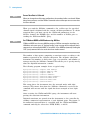
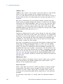
Agilent InfiniiVision
5000 Series
Oscilloscopes
Programmer's Guide
Notices
© Agilent Technologies, Inc. 2005-2010
Manual Part Number
No part of this manual may be reproduced
in any form or by any means (including
electronic storage and retrieval or translation into a foreign language) without prior
agreement and written consent from Agilent Technologies, Inc. as governed by
United States and international copyright
laws.
Version 06.10.0001
Trademarks
Microsoft®, MS-DOS®, Windows®, Windows 2000®, and Windows XP® are U.S.
registered trademarks of Microsoft Corporation.
Adobe®, Acrobat®, and the Acrobat
Logo® are trademarks of Adobe Systems
Incorporated.
Edition
June 30, 2010
Available in electronic format only
Agilent Technologies, Inc.
1900 Garden of the Gods Road
Colorado Springs, CO 80907 USA
agency regulation or contract clause. Use,
duplication or disclosure of Software is
subject to Agilent Technologies’ standard
commercial license terms, and non-DOD
Departments and Agencies of the U.S. Government will receive no greater than
Restricted Rights as defined in FAR
52.227-19(c)(1-2) (June 1987). U.S. Government users will receive no greater than
Limited Rights as defined in FAR 52.227-14
(June 1987) or DFAR 252.227-7015 (b)(2)
(November 1995), as applicable in any
technical data.
Warranty
The material contained in this document is provided “as is,” and is subject to being changed, without notice,
in future editions. Further, to the maximum extent permitted by applicable
law, Agilent disclaims all warranties,
either express or implied, with regard
to this manual and any information
contained herein, including but not
limited to the implied warranties of
merchantability and fitness for a particular purpose. Agilent shall not be
liable for errors or for incidental or
consequential damages in connection
with the furnishing, use, or performance of this document or of any
information contained herein. Should
Agilent and the user have a separate
written agreement with warranty
terms covering the material in this
document that conflict with these
terms, the warranty terms in the separate agreement shall control.
Technology Licenses
The hardware and/or software described in
this document are furnished under a
license and may be used or copied only in
accordance with the terms of such license.
Restricted Rights Legend
If software is for use in the performance of
a U.S. Government prime contract or subcontract, Software is delivered and
licensed as “Commercial computer software” as defined in DFAR 252.227-7014
(June 1995), or as a “commercial item” as
defined in FAR 2.101(a) or as “Restricted
computer software” as defined in FAR
52.227-19 (June 1987) or any equivalent
Safety Notices
CAUTION
A CAUTION notice denotes a hazard. It calls attention to an operating procedure, practice, or the like
that, if not correctly performed or
adhered to, could result in damage
to the product or loss of important
data. Do not proceed beyond a
CAUTION notice until the indicated
conditions are fully understood and
met.
WA R N I N G
A WARNING notice denotes a
hazard. It calls attention to an
operating procedure, practice, or
the like that, if not correctly performed or adhered to, could result
in personal injury or death. Do not
proceed beyond a WARNING
notice until the indicated conditions are fully understood and met.
In This Book
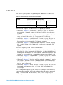
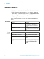
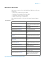
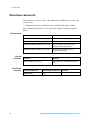
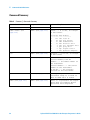
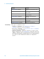
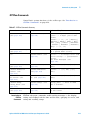
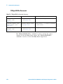
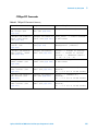
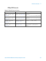
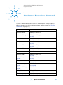
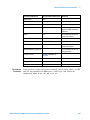
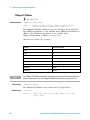
This book is your guide to programming the 5000 Series oscilloscopes:
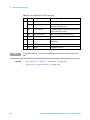
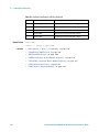
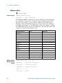
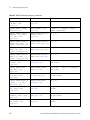
Table 1
Channels
InfiniiVision 5000 Series Oscilloscope Models
Input Bandwidth (Maximum Sample Rate)
500 MHz (4 GSa/s)
300 MHz (2 GSa/s)
100 MHz (2 GSa/s)
4 analog
DSO5054A
DSO5034A
DSO5014A
2 analog
DSO5052A
DSO5032A
DSO5012A
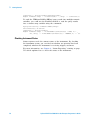
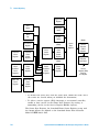
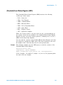
The first few chapters describe how to set up and get started:
• Chapter 1, Chapter 1, “What's New,” starting on page 21, describes
programming command changes in the latest version of oscilloscope
software.
• Chapter 2, Chapter 2, “Setting Up,” starting on page 37, describes the
steps you must take before you can program the oscilloscope.
• Chapter 3, Chapter 3, “Getting Started,” starting on page 47, gives a
general overview of oscilloscope program structure and shows how to
program the oscilloscope using a few simple examples.
• Chapter 4, Chapter 4, “Commands Quick Reference,” starting on page
61, is a brief listing of the 5000 Series oscilloscope commands and
syntax.
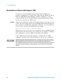
The next chapters provide reference information:
• Chapter 5, Chapter 5, “Commands by Subsystem,” starting on page 109,
describes the set of commands that belong to an individual subsystem
and explains the function of each command. Command arguments and
syntax are described. Some command descriptions have example code.
• Chapter 6, Chapter 6, “Commands A- Z,” starting on page 625, contains
an alphabetical listing of all command elements.
• Chapter 7, Chapter 7, “Obsolete and Discontinued Commands,” starting
on page 657, describes obsolete commands which still work but have
been replaced by newer commands and discontinued commands which
are no longer supported.
• Chapter 8, Chapter 8, “Error Messages,” starting on page 707, lists the
instrument error messages that can occur while programming the
oscilloscope.
The command descriptions in this reference show upper and lowercase
characters. For example, :AUToscale indicates that the entire command
name is :AUTOSCALE. The short form, :AUT, is also accepted by the
oscilloscope.
Agilent InfiniiVision 5000 Series Oscilloscopes Programmer's Guide
3
Then, there are chapters that describe programming topics and conceptual
information in more detail:
• Chapter 9, Chapter 9, “Status Reporting,” starting on page 715,
describes the oscilloscope's status registers and how to check the status
of the instrument.
• Chapter 10, Chapter 10, “Synchronizing Acquisitions,” starting on page
739, describes how to wait for acquisitions to complete before querying
measurement results or performing other operations with the captured
data.
• Chapter 11, Chapter 11, “More About Oscilloscope Commands,” starting
on page 749, contains additional information about oscilloscope
programming commands.
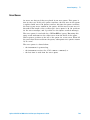
Finally, there is a chapter that contains programming examples:
• Chapter 12, Chapter 12, “Programming Examples,” starting on page 775.
See Also
• For more information on using the SICL, VISA, and VISA COM libraries
in general, see the documentation that comes with the Agilent IO
Libraries Suite.
• For information on controller PC interface configuration, see the
documentation for the interface card used (for example, the Agilent
82350A GPIB interface).
• For information on oscilloscope front- panel operation, see the User's
Guide.
• For detailed connectivity information, refer to the Agilent Technologies
USB/LAN/GPIB Connectivity Guide. For a printable electronic copy of
the Connectivity Guide, direct your Web browser to "www.agilent.com"
and search for "Connectivity Guide".
• For the latest versions of this and other manuals, see:
"http://www.agilent.com/find/5000manual"
4
Agilent InfiniiVision 5000 Series Oscilloscopes Programmer's Guide
Contents
In This Book
3
1 What's New
What's New in Version 6.10
22
What's New in Version 6.00
23
What's New in Version 5.25
25
What's New in Version 5.20
27
What's New in Version 5.15
30
What's New in Version 5.10
32
What's New in Version 5.00
33
What's New in Version 4.10
35
Version 4.00 at Introduction
36
2 Setting Up
Step 1. Install Agilent IO Libraries Suite software
Step 2. Connect and set up the oscilloscope
Using the USB (Device) Interface 39
Using the LAN Interface 39
Using the GPIB Interface 40
Step 3. Verify the oscilloscope connection
38
39
41
3 Getting Started
Basic Oscilloscope Program Structure
Initializing 48
Capturing Data 48
Analyzing Captured Data 49
48
Agilent InfiniiVision 5000 Series Oscilloscopes Programmer's Guide
5
Programming the Oscilloscope 50
Referencing the IO Library 50
Opening the Oscilloscope Connection via the IO Library 51
Initializing the Interface and the Oscilloscope 51
Using :AUToscale to Automate Oscilloscope Setup 52
Using Other Oscilloscope Setup Commands 52
Capturing Data with the :DIGitize Command 53
Reading Query Responses from the Oscilloscope 55
Reading Query Results into String Variables 56
Reading Query Results into Numeric Variables 56
Reading Definite-Length Block Query Response Data 56
Sending Multiple Queries and Reading Results 57
Checking Instrument Status 58
Other Ways of Sending Commands 59
Telnet Sockets 59
Sending SCPI Commands Using Browser Web Control
59
4 Commands Quick Reference
Command Summary
62
Syntax Elements 106
Number Format 106
<NL> (Line Terminator) 106
[ ] (Optional Syntax Terms) 106
{ } (Braces) 106
::= (Defined As) 106
< > (Angle Brackets) 107
... (Ellipsis) 107
n,..,p (Value Ranges) 107
d (Digits) 107
Quoted ASCII String 107
Definite-Length Block Response Data
107
5 Commands by Subsystem
Common (*) Commands 111
*CLS (Clear Status) 115
*ESE (Standard Event Status Enable) 116
*ESR (Standard Event Status Register) 118
*IDN (Identification Number) 120
*LRN (Learn Device Setup) 121
*OPC (Operation Complete) 122
6
Agilent InfiniiVision 5000 Series Oscilloscopes Programmer's Guide
*OPT (Option Identification) 123
*RCL (Recall) 124
*RST (Reset) 125
*SAV (Save) 128
*SRE (Service Request Enable) 129
*STB (Read Status Byte) 131
*TRG (Trigger) 133
*TST (Self Test) 134
*WAI (Wait To Continue) 135
Root (:) Commands 136
:AER (Arm Event Register) 139
:AUToscale 140
:AUToscale:AMODE 142
:AUToscale:CHANnels 143
:BLANk 144
:CDISplay 145
:DIGitize 146
:HWEenable (Hardware Event Enable Register) 148
:HWERegister:CONDition (Hardware Event Condition Register)
:HWERegister[:EVENt] (Hardware Event Event Register) 152
:MERGe 154
:MTEenable (Mask Test Event Enable Register) 155
:MTERegister[:EVENt] (Mask Test Event Event Register) 157
:OPEE (Operation Status Enable Register) 159
:OPERegister:CONDition (Operation Status Condition Register)
:OPERegister[:EVENt] (Operation Status Event Register) 163
:OVLenable (Overload Event Enable Register) 165
:OVLRegister (Overload Event Register) 167
:PRINt 169
:RUN 170
:SERial 171
:SINGle 172
:STATus 173
:STOP 174
:TER (Trigger Event Register) 175
:VIEW 176
150
161
:ACQuire Commands 177
:ACQuire:AALias 179
:ACQuire:COMPlete 180
:ACQuire:COUNt 181
:ACQuire:DAALias 182
Agilent InfiniiVision 5000 Series Oscilloscopes Programmer's Guide
7
:ACQuire:MODE 183
:ACQuire:POINts 184
:ACQuire:SEGMented:ANALyze 185
:ACQuire:SEGMented:COUNt 186
:ACQuire:SEGMented:INDex 187
:ACQuire:SRATe 190
:ACQuire:TYPE 191
:CALibrate Commands 193
:CALibrate:DATE 195
:CALibrate:LABel 196
:CALibrate:OUTPut 197
:CALibrate:STARt 198
:CALibrate:STATus 199
:CALibrate:SWITch 200
:CALibrate:TEMPerature 201
:CALibrate:TIME 202
:CHANnel<n> Commands 203
:CHANnel<n>:BWLimit 206
:CHANnel<n>:COUPling 207
:CHANnel<n>:DISPlay 208
:CHANnel<n>:IMPedance 209
:CHANnel<n>:INVert 210
:CHANnel<n>:LABel 211
:CHANnel<n>:OFFSet 212
:CHANnel<n>:PROBe 213
:CHANnel<n>:PROBe:HEAD[:TYPE]
:CHANnel<n>:PROBe:ID 215
:CHANnel<n>:PROBe:SKEW 216
:CHANnel<n>:PROBe:STYPe 217
:CHANnel<n>:PROTection 218
:CHANnel<n>:RANGe 219
:CHANnel<n>:SCALe 220
:CHANnel<n>:UNITs 221
:CHANnel<n>:VERNier 222
214
:DISPlay Commands 223
:DISPlay:CLEar 225
:DISPlay:DATA 226
:DISPlay:LABel 228
:DISPlay:LABList 229
:DISPlay:PERSistence 230
8
Agilent InfiniiVision 5000 Series Oscilloscopes Programmer's Guide
:DISPlay:SOURce
:DISPlay:VECTors
231
232
:EXTernal Trigger Commands 233
:EXTernal:BWLimit 235
:EXTernal:IMPedance 236
:EXTernal:PROBe 237
:EXTernal:PROBe:ID 238
:EXTernal:PROBe:STYPe 239
:EXTernal:PROTection 240
:EXTernal:RANGe 241
:EXTernal:UNITs 242
:FUNCtion Commands 243
:FUNCtion:CENTer 246
:FUNCtion:DISPlay 247
:FUNCtion:GOFT:OPERation 248
:FUNCtion:GOFT:SOURce1 249
:FUNCtion:GOFT:SOURce2 250
:FUNCtion:OFFSet 251
:FUNCtion:OPERation 252
:FUNCtion:RANGe 253
:FUNCtion:REFerence 254
:FUNCtion:SCALe 255
:FUNCtion:SOURce1 256
:FUNCtion:SOURce2 257
:FUNCtion:SPAN 258
:FUNCtion:WINDow 259
:HARDcopy Commands 260
:HARDcopy:AREA 262
:HARDcopy:APRinter 263
:HARDcopy:FACTors 264
:HARDcopy:FFEed 265
:HARDcopy:INKSaver 266
:HARDcopy:LAYout 267
:HARDcopy:PALette 268
:HARDcopy:PRINter:LIST 269
:HARDcopy:STARt 270
:LISTer Commands 271
:LISTer:DATA 272
:LISTer:DISPlay 273
:MARKer Commands
274
Agilent InfiniiVision 5000 Series Oscilloscopes Programmer's Guide
9
:MARKer:MODE 276
:MARKer:X1Position 277
:MARKer:X1Y1source 278
:MARKer:X2Position 279
:MARKer:X2Y2source 280
:MARKer:XDELta 281
:MARKer:Y1Position 282
:MARKer:Y2Position 283
:MARKer:YDELta 284
:MEASure Commands 285
:MEASure:CLEar 292
:MEASure:COUNter 293
:MEASure:DEFine 294
:MEASure:DELay 297
:MEASure:DUTYcycle 299
:MEASure:FALLtime 300
:MEASure:FREQuency 301
:MEASure:NWIDth 302
:MEASure:OVERshoot 303
:MEASure:PERiod 305
:MEASure:PHASe 306
:MEASure:PREShoot 307
:MEASure:PWIDth 308
:MEASure:RESults 309
:MEASure:RISetime 312
:MEASure:SDEViation 313
:MEASure:SHOW 314
:MEASure:SOURce 315
:MEASure:STATistics 317
:MEASure:STATistics:INCRement 318
:MEASure:STATistics:RESet 319
:MEASure:TEDGe 320
:MEASure:TVALue 322
:MEASure:VAMPlitude 324
:MEASure:VAVerage 325
:MEASure:VBASe 326
:MEASure:VMAX 327
:MEASure:VMIN 328
:MEASure:VPP 329
:MEASure:VRATio 330
:MEASure:VRMS 331
10
Agilent InfiniiVision 5000 Series Oscilloscopes Programmer's Guide
:MEASure:VTIMe 332
:MEASure:VTOP 333
:MEASure:WINDow 334
:MEASure:XMAX 335
:MEASure:XMIN 336
:MTESt Commands 337
:MTESt:AMASk:CREate 342
:MTESt:AMASk:SOURce 343
:MTESt:AMASk:UNITs 344
:MTESt:AMASk:XDELta 345
:MTESt:AMASk:YDELta 346
:MTESt:COUNt:FWAVeforms 347
:MTESt:COUNt:RESet 348
:MTESt:COUNt:TIME 349
:MTESt:COUNt:WAVeforms 350
:MTESt:DATA 351
:MTESt:DELete 352
:MTESt:ENABle 353
:MTESt:LOCK 354
:MTESt:OUTPut 355
:MTESt:RMODe 356
:MTESt:RMODe:FACTion:MEASure 357
:MTESt:RMODe:FACTion:PRINt 358
:MTESt:RMODe:FACTion:SAVE 359
:MTESt:RMODe:FACTion:STOP 360
:MTESt:RMODe:SIGMa 361
:MTESt:RMODe:TIME 362
:MTESt:RMODe:WAVeforms 363
:MTESt:SCALe:BIND 364
:MTESt:SCALe:X1 365
:MTESt:SCALe:XDELta 366
:MTESt:SCALe:Y1 367
:MTESt:SCALe:Y2 368
:MTESt:SOURce 369
:MTESt:TITLe 370
:RECall Commands 371
:RECall:FILename 372
:RECall:IMAGe[:STARt] 373
:RECall:MASK[:STARt] 374
:RECall:PWD 375
:RECall:SETup[:STARt] 376
Agilent InfiniiVision 5000 Series Oscilloscopes Programmer's Guide
11
:SAVE Commands 377
:SAVE:FILename 379
:SAVE:IMAGe[:STARt] 380
:SAVE:IMAGe:AREA 381
:SAVE:IMAGe:FACTors 382
:SAVE:IMAGe:FORMat 383
:SAVE:IMAGe:INKSaver 384
:SAVE:IMAGe:PALette 385
:SAVE:LISTer[:STARt] 386
:SAVE:MASK[:STARt] 387
:SAVE:PWD 388
:SAVE:SETup[:STARt] 389
:SAVE:WAVeform[:STARt] 390
:SAVE:WAVeform:FORMat 391
:SAVE:WAVeform:LENGth 392
:SAVE:WAVeform:SEGMented 393
:SBUS Commands 394
:SBUS:CAN:COUNt:ERRor 396
:SBUS:CAN:COUNt:OVERload 397
:SBUS:CAN:COUNt:RESet 398
:SBUS:CAN:COUNt:TOTal 399
:SBUS:CAN:COUNt:UTILization 400
:SBUS:DISPlay 401
:SBUS:FLEXray:COUNt:NULL 402
:SBUS:FLEXray:COUNt:RESet 403
:SBUS:FLEXray:COUNt:SYNC 404
:SBUS:FLEXray:COUNt:TOTal 405
:SBUS:I2S:BASE 406
:SBUS:IIC:ASIZe 407
:SBUS:LIN:PARity 408
:SBUS:M1553:BASE 409
:SBUS:MODE 410
:SBUS:SPI:BITorder 411
:SBUS:SPI:WIDTh 412
:SBUS:UART:BASE 413
:SBUS:UART:COUNt:ERRor 414
:SBUS:UART:COUNt:RESet 415
:SBUS:UART:COUNt:RXFRames 416
:SBUS:UART:COUNt:TXFRames 417
:SBUS:UART:FRAMing 418
:SYSTem Commands
12
419
Agilent InfiniiVision 5000 Series Oscilloscopes Programmer's Guide
:SYSTem:DATE 420
:SYSTem:DSP 421
:SYSTem:ERRor 422
:SYSTem:LOCK 423
:SYSTem:PRECision 424
:SYSTem:PROTection:LOCK
:SYSTem:SETup 426
:SYSTem:TIME 428
425
:TIMebase Commands 429
:TIMebase:MODE 431
:TIMebase:POSition 432
:TIMebase:RANGe 433
:TIMebase:REFerence 434
:TIMebase:SCALe 435
:TIMebase:VERNier 436
:TIMebase:WINDow:POSition 437
:TIMebase:WINDow:RANGe 438
:TIMebase:WINDow:SCALe 439
:TRIGger Commands 440
General :TRIGger Commands 443
:TRIGger:HFReject 444
:TRIGger:HOLDoff 445
:TRIGger:LFIFty 446
:TRIGger:MODE 447
:TRIGger:NREJect 448
:TRIGger:PATTern 449
:TRIGger:SWEep 451
:TRIGger:CAN Commands 452
:TRIGger:CAN:PATTern:DATA 454
:TRIGger:CAN:PATTern:DATA:LENGth 455
:TRIGger:CAN:PATTern:ID 456
:TRIGger:CAN:PATTern:ID:MODE 457
:TRIGger:CAN:SAMPlepoint 458
:TRIGger:CAN:SIGNal:BAUDrate 459
:TRIGger:CAN:SIGNal:DEFinition 460
:TRIGger:CAN:SOURce 461
:TRIGger:CAN:TRIGger 462
:TRIGger:DURation Commands 464
:TRIGger:DURation:GREaterthan 465
:TRIGger:DURation:LESSthan 466
:TRIGger:DURation:PATTern 467
Agilent InfiniiVision 5000 Series Oscilloscopes Programmer's Guide
13
:TRIGger:DURation:QUALifier 468
:TRIGger:DURation:RANGe 469
:TRIGger:EBURst Commands 470
:TRIGger:EBURst:COUNt 471
:TRIGger:EBURst:IDLE 472
:TRIGger:EBURst:SLOPe 473
:TRIGger[:EDGE] Commands 474
:TRIGger[:EDGE]:COUPling 475
:TRIGger[:EDGE]:LEVel 476
:TRIGger[:EDGE]:REJect 477
:TRIGger[:EDGE]:SLOPe 478
:TRIGger[:EDGE]:SOURce 479
:TRIGger:FLEXray Commands 480
:TRIGger:FLEXray:AUTosetup 481
:TRIGger:FLEXray:BAUDrate 482
:TRIGger:FLEXray:CHANnel 483
:TRIGger:FLEXray:ERRor:TYPE 484
:TRIGger:FLEXray:EVENt:TYPE 485
:TRIGger:FLEXray:FRAMe:CCBase 486
:TRIGger:FLEXray:FRAMe:CCRepetition 487
:TRIGger:FLEXray:FRAMe:ID 488
:TRIGger:FLEXray:FRAMe:TYPE 489
:TRIGger:FLEXray:SOURce 490
:TRIGger:FLEXray:TRIGger 491
:TRIGger:GLITch Commands 492
:TRIGger:GLITch:GREaterthan 493
:TRIGger:GLITch:LESSthan 494
:TRIGger:GLITch:LEVel 495
:TRIGger:GLITch:POLarity 496
:TRIGger:GLITch:QUALifier 497
:TRIGger:GLITch:RANGe 498
:TRIGger:GLITch:SOURce 499
:TRIGger:I2S Commands 500
:TRIGger:I2S:ALIGnment 502
:TRIGger:I2S:AUDio 503
:TRIGger:I2S:CLOCk:SLOPe 504
:TRIGger:I2S:PATTern:DATA 505
:TRIGger:I2S:PATTern:FORMat 507
:TRIGger:I2S:RANGe 508
:TRIGger:I2S:RWIDth 510
:TRIGger:I2S:SOURce:CLOCk 511
:TRIGger:I2S:SOURce:DATA 512
14
Agilent InfiniiVision 5000 Series Oscilloscopes Programmer's Guide
:TRIGger:I2S:SOURce:WSELect 513
:TRIGger:I2S:TRIGger 514
:TRIGger:I2S:TWIDth 516
:TRIGger:I2S:WSLow 517
:TRIGger:IIC Commands 518
:TRIGger:IIC:PATTern:ADDRess 519
:TRIGger:IIC:PATTern:DATA 520
:TRIGger:IIC:PATTern:DATa2 521
:TRIGger:IIC[:SOURce]:CLOCk 522
:TRIGger:IIC[:SOURce]:DATA 523
:TRIGger:IIC:TRIGger:QUALifier 524
:TRIGger:IIC:TRIGger[:TYPE] 525
:TRIGger:LIN Commands 527
:TRIGger:LIN:ID 529
:TRIGger:LIN:PATTern:DATA 530
:TRIGger:LIN:PATTern:DATA:LENGth 532
:TRIGger:LIN:PATTern:FORMat 533
:TRIGger:LIN:SAMPlepoint 534
:TRIGger:LIN:SIGNal:BAUDrate 535
:TRIGger:LIN:SOURce 536
:TRIGger:LIN:STANdard 537
:TRIGger:LIN:SYNCbreak 538
:TRIGger:LIN:TRIGger 539
:TRIGger:M1553 Commands 540
:TRIGger:M1553:AUTosetup 541
:TRIGger:M1553:PATTern:DATA 542
:TRIGger:M1553:RTA 543
:TRIGger:M1553:SOURce:LOWer 544
:TRIGger:M1553:SOURce:UPPer 545
:TRIGger:M1553:TYPE 546
:TRIGger:SEQuence Commands 547
:TRIGger:SEQuence:COUNt 548
:TRIGger:SEQuence:EDGE 549
:TRIGger:SEQuence:FIND 550
:TRIGger:SEQuence:PATTern 551
:TRIGger:SEQuence:RESet 552
:TRIGger:SEQuence:TIMer 553
:TRIGger:SEQuence:TRIGger 554
:TRIGger:SPI Commands 555
:TRIGger:SPI:CLOCk:SLOPe 556
:TRIGger:SPI:CLOCk:TIMeout 557
:TRIGger:SPI:FRAMing 558
Agilent InfiniiVision 5000 Series Oscilloscopes Programmer's Guide
15
:TRIGger:SPI:PATTern:DATA 559
:TRIGger:SPI:PATTern:WIDTh 560
:TRIGger:SPI:SOURce:CLOCk 561
:TRIGger:SPI:SOURce:DATA 562
:TRIGger:SPI:SOURce:FRAMe 563
:TRIGger:TV Commands 564
:TRIGger:TV:LINE 565
:TRIGger:TV:MODE 566
:TRIGger:TV:POLarity 567
:TRIGger:TV:SOURce 568
:TRIGger:TV:STANdard 569
:TRIGger:UART Commands 570
:TRIGger:UART:BASE 572
:TRIGger:UART:BAUDrate 573
:TRIGger:UART:BITorder 574
:TRIGger:UART:BURSt 575
:TRIGger:UART:DATA 576
:TRIGger:UART:IDLE 577
:TRIGger:UART:PARity 578
:TRIGger:UART:POLarity 579
:TRIGger:UART:QUALifier 580
:TRIGger:UART:SOURce:RX 581
:TRIGger:UART:SOURce:TX 582
:TRIGger:UART:TYPE 583
:TRIGger:UART:WIDTh 584
:TRIGger:USB Commands 585
:TRIGger:USB:SOURce:DMINus 586
:TRIGger:USB:SOURce:DPLus 587
:TRIGger:USB:SPEed 588
:TRIGger:USB:TRIGger 589
:WAVeform Commands 590
:WAVeform:BYTeorder 597
:WAVeform:COUNt 598
:WAVeform:DATA 599
:WAVeform:FORMat 601
:WAVeform:POINts 602
:WAVeform:POINts:MODE 604
:WAVeform:PREamble 606
:WAVeform:SEGMented:COUNt 609
:WAVeform:SEGMented:TTAG 610
:WAVeform:SOURce 611
16
Agilent InfiniiVision 5000 Series Oscilloscopes Programmer's Guide
:WAVeform:SOURce:SUBSource
:WAVeform:TYPE 616
:WAVeform:UNSigned 617
:WAVeform:VIEW 618
:WAVeform:XINCrement 619
:WAVeform:XORigin 620
:WAVeform:XREFerence 621
:WAVeform:YINCrement 622
:WAVeform:YORigin 623
:WAVeform:YREFerence 624
615
6 Commands A-Z
7 Obsolete and Discontinued Commands
:CHANnel:LABel 662
:CHANnel2:SKEW 663
:CHANnel<n>:INPut 664
:CHANnel<n>:PMODe 665
:DISPlay:CONNect 666
:ERASe 667
:EXTernal:INPut 668
:EXTernal:PMODe 669
:FUNCtion:SOURce 670
:FUNCtion:VIEW 671
:HARDcopy:DESTination 672
:HARDcopy:DEVice 673
:HARDcopy:FILename 674
:HARDcopy:FORMat 675
:HARDcopy:GRAYscale 676
:HARDcopy:IGColors 677
:HARDcopy:PDRiver 678
:MEASure:LOWer 679
:MEASure:SCRatch 680
:MEASure:TDELta 681
:MEASure:THResholds 682
:MEASure:TMAX 683
:MEASure:TMIN 684
:MEASure:TSTArt 685
:MEASure:TSTOp 686
:MEASure:TVOLt 687
:MEASure:UPPer 689
:MEASure:VDELta 690
Agilent InfiniiVision 5000 Series Oscilloscopes Programmer's Guide
17
:MEASure:VSTArt 691
:MEASure:VSTOp 692
:MTESt:AMASk:{SAVE | STORe} 693
:MTESt:AVERage 694
:MTESt:AVERage:COUNt 695
:MTESt:LOAD 696
:MTESt:RUMode 697
:MTESt:RUMode:SOFailure 698
:MTESt:{STARt | STOP} 699
:MTESt:TRIGger:SOURce 700
:PRINt? 701
:TIMebase:DELay 703
:TRIGger:CAN:ACKNowledge 704
:TRIGger:LIN:SIGNal:DEFinition 705
:TRIGger:TV:TVMode 706
8 Error Messages
9 Status Reporting
Status Reporting Data Structures
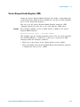
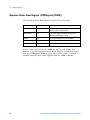
Status Byte Register (STB)
718
721
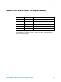
Service Request Enable Register (SRE)
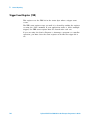
Trigger Event Register (TER)
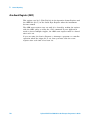
Output Queue
723
724
725
Message Queue
726
(Standard) Event Status Register (ESR)
727
(Standard) Event Status Enable Register (ESE)
Error Queue
728
729
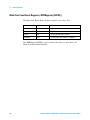
Operation Status Event Register (:OPERegister[:EVENt])
730
Operation Status Condition Register (:OPERegister:CONDition)
Arm Event Register (AER)
732
Overload Event Register (:OVLRegister)
733
Hardware Event Event Register (:HWERegister[:EVENt])
734
Hardware Event Condition Register (:HWERegister:CONDition)
Mask Test Event Event Register (:MTERegister[:EVENt])
Clearing Registers and Queues
18
731
735
736
737
Agilent InfiniiVision 5000 Series Oscilloscopes Programmer's Guide
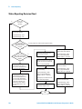
Status Reporting Decision Chart
738
10 Synchronizing Acquisitions
Synchronization in the Programming Flow
Set Up the Oscilloscope 740
Acquire a Waveform 740
Retrieve Results 740
Blocking Synchronization
740
741
Polling Synchronization With Timeout
742
Synchronizing with a Single-Shot Device Under Test (DUT)
Synchronization with an Averaging Acquisition
744
746
11 More About Oscilloscope Commands
Command Classifications 750
Core Commands 750
Non-Core Commands 750
Obsolete Commands 750
Valid Command/Query Strings 751
Program Message Syntax
751
Command Tree 755
Duplicate Mnemonics 769
Tree Traversal Rules and Multiple Commands
Query Return Values
769
772
All Oscilloscope Commands Are Sequential
773
12 Programming Examples
VISA COM Examples 776
VISA COM Example in Visual Basic 776
VISA COM Example in C# 786
VISA COM Example in Visual Basic .NET 798
VISA Examples 809
VISA Example in C 809
VISA Example in Visual Basic 818
VISA Example in C# 828
VISA Example in Visual Basic .NET 841
SICL Examples 855
SICL Example in C 855
SICL Example in Visual Basic
864
Agilent InfiniiVision 5000 Series Oscilloscopes Programmer's Guide
19
Index
20
Agilent InfiniiVision 5000 Series Oscilloscopes Programmer's Guide
Agilent InfiniiVision 5000 Series Oscilloscopes
Programmer's Guide
1
What's New
What's New in Version 6.10
What's New in Version 6.00
What's New in Version 5.25
What's New in Version 5.20
What's New in Version 5.15
What's New in Version 5.10
What's New in Version 5.00
What's New in Version 4.10
Version 4.00 at Introduction
22
23
25
27
30
32
33
35
36
21
1
What's New
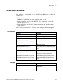
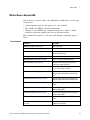
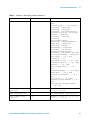
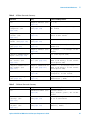
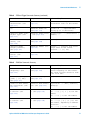
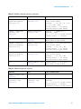
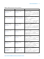
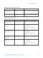
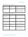
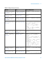
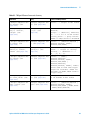
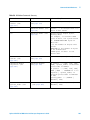
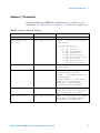
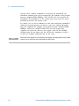
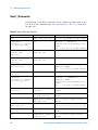
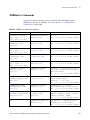
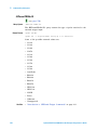
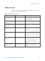
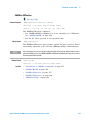
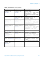
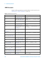
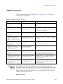
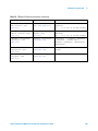
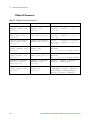
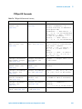
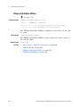
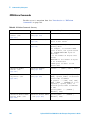
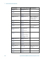
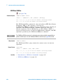
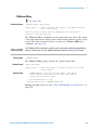
What's New in Version 6.10
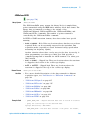
New features in version 6.10 of the InfiniiVision 5000 Series oscilloscope
software are:
• When the zoomed time base mode is on, you can select whether the
Main window or the Zoom window is used as the measurement window.
• An interval specification for the V average and dc RMS measurements
has been added.
• A 50% trigger level command.
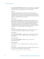
More detailed descriptions of the new and changed commands appear
below.
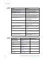
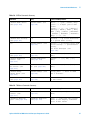
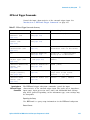
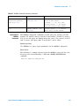
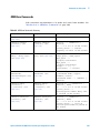
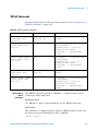
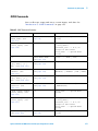
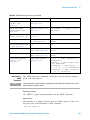
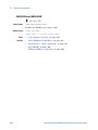
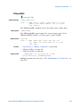
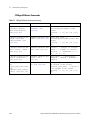
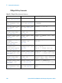
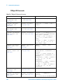
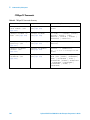
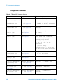
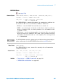
New Commands
Changed
Commands
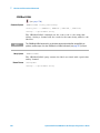
22
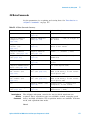
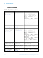
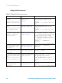
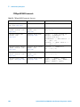
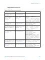
Command
Description
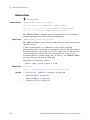
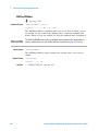
:MEASure:WINDow (see page 334)
When the zoomed time base mode is on,
specifies whether the Main window or the
Zoom window is used as the measurement
window.
:TRIGger:LFIFty (see page 446)
Sets the trigger level of a displayed analog
channel trigger source to the waveform's 50%
value.
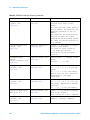
Command
Differences
:MEASure:VAVerage (see page 325)
There is now an option for specifying the
interval.
:MEASure:VRMS (see page 331)
There is now an option for specifying the
interval.
:TRIGger:CAN:SIGNal:DEFinition (see
page 460)
There are now DIFH (differential H-L) and DIFL
(differential L-H) options. The DIFL option is the
same as the existing DIFFerential option. Also,
this command is no longer classified as
obsolete.
Agilent InfiniiVision 5000 Series Oscilloscopes Programmer's Guide
1
What's New
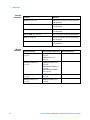
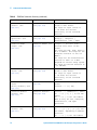
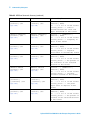
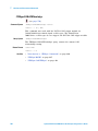
What's New in Version 6.00
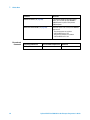
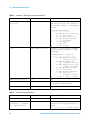
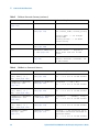
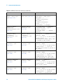
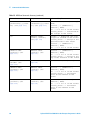
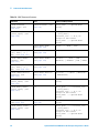
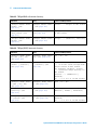
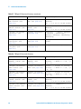
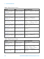
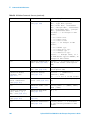
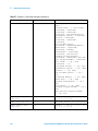
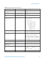
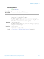
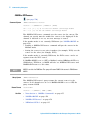
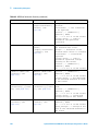
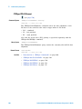
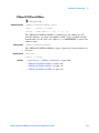
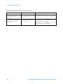
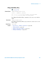
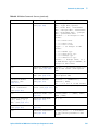
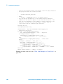
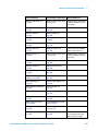
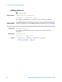
New features in version 6.00 of the InfiniiVision 5000 Series oscilloscope
software are:
• The ability to perform measurements and math functions on a
10K- point (maximum) precision analysis data record.
• Support for the new N5469A MIL- STD 1553 triggering and decode
option (Option 553).
• Support for the new N5432C FlexRay triggering and decode option
(Option FLX).
More detailed descriptions of the new and changed commands appear
below.
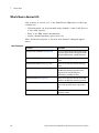
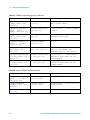
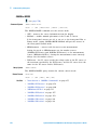
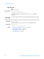
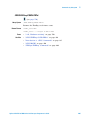
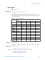
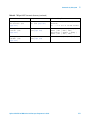
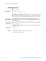
New Commands
Changed
Commands
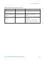
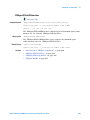
Command
Description
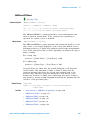
:SBUS:FLEXray:COUNt:NULL? (see page 402)
Returns the FlexRay null frame count.
:SBUS:FLEXray:COUNt:RESet (see page 403)
Resets the FlexRay frame counters.
:SBUS:FLEXray:COUNt:SYNC? (see page 404)
Returns the FlexRay sync frame count.
:SBUS:FLEXray:COUNt:TOTal? (see page 405)
Returns the FlexRay total frame count.
:SBUS:M1553:BASE (see page 409)
Determines the base to use for the MIL-STD
1553 decode display.
:SBUS:SPI:BITorder (see page 411)
Selects the bit order used when displaying data
in the SPI serial decode waveform and in the
Lister.
:SYSTem:PRECision (see page 424)
Allows measurements and math functions to
be performed on a precision analysis record (at
the expense of waveform update rate).
:TRIGger:FLEXray Commands (see page 500)
Commands for triggering on FlexRay signals.
:TRIGger:M1553 Commands (see page 540)
Commands for triggering on MIL-STD 1553
signals.
Command
Differences
:SBUS:MODE (see page 410)
You can now select the M1553 serial bus
decode mode.
:TRIGger:MODE (see page 447)
You can now select the M1553 trigger mode.
Agilent InfiniiVision 5000 Series Oscilloscopes Programmer's Guide
23
1
What's New
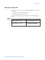
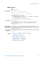
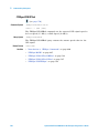
Discontinued
Commands
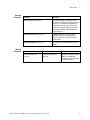
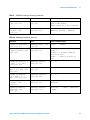
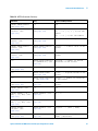
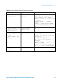
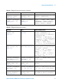
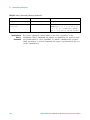
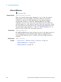
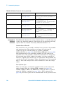
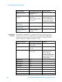
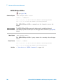
24
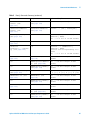
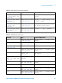
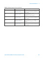
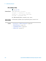
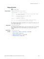
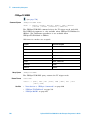
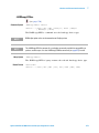
Command
Differences
:WAVeform:POINts (see page 604)
In the RAW or MAXimum waveform points
modes, you can now specify 4,000,000 or
8,000,000 points in place of the previous
5,000,000 option.
:WAVeform:POINts:MODE (see page 604)
Command syntax is the same, but the NORMal
mode returns:
• The measurement record when
:SYSTem:PRECision is OFF.
• The precision analysis record when
:SYSTem:PRECision is ON.
Discontinued Command
Current Command Equivalent
:DISPlay:FREeze
none
Comments
Agilent InfiniiVision 5000 Series Oscilloscopes Programmer's Guide
1
What's New
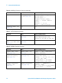
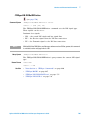
What's New in Version 5.25
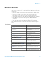
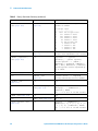
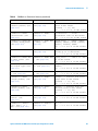
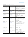
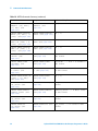
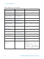
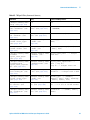
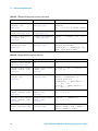
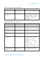
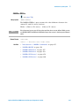
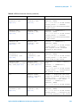
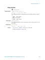
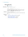
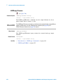
New features in version 5.25 of the InfiniiVision 5000 Series oscilloscope
software are:
• The Lister display for showing decoded serial data in tabular format.
• The ability to trigger on and decode I2S serial bus data with a
four- channel oscilloscope that includes the Option SND license.
• The EBURst trigger mode and supporting :TRIGger:EBURst commands.
• The SEQuence trigger mode and supporting :TRIGger:SEQuence
commands.
• The USB trigger mode and supporting :TRIGger:USB commands.
More detailed descriptions of the new and changed commands appear
below.
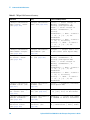
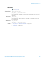
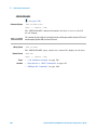
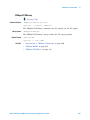
New Commands
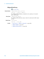
Command
Description
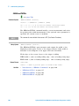
:CHANnel<n>:PROBe:HEAD[:TYPE] (see
page 214)
Sets an analog channel probe head type and dB
value.
:DISPlay:FREeze
Freezes the display without stopping currently
running acquisitions.
:LISTer Commands (see page 271)
Commands for turning the Lister display on/off
and for returning the Lister data.
:MTESt:RMODe:FACTion:MEASure (see
page 357)
Lets you enable or disable measurements on
mask test failures.
:SAVE:LISTer[:STARt] (see page 386)
Saves the Lister display data to a file.
:SBUS:I2S:BASE (see page 406)
Determines the base to use for the I2S decode
display.
:TRIGger:EBURst Commands (see page 470)
Commands for triggering on the Nth edge of a
burst that occurs after an idle time.
:TRIGger:I2S Commands (see page 500)
Commands for triggering on I2S signals.
:TRIGger:LIN:PATTern:DATA (see page 530)
Sets the data value when triggering on a LIN
frame ID and data.
:TRIGger:LIN:PATTern:DATA:LENGth (see
page 532)
Sets the byte length of the LIN data string.
:TRIGger:LIN:PATTern:FORMat (see page 533)
Sets the entry (and query) number base used
by the :TRIGger:LIN:PATTern:DATA command.
Agilent InfiniiVision 5000 Series Oscilloscopes Programmer's Guide
25
1
What's New
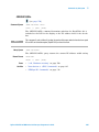
Changed
Commands
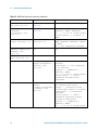
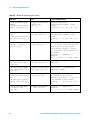
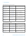
26
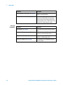
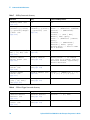
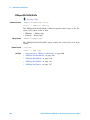
Command
Description
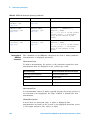
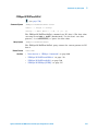
:TRIGger:SEQuence Commands (see page 547)
Commands for triggering the oscilloscope after
finding a sequence of events.
:TRIGger:USB Commands (see page 585)
Commands for triggering on a Start of Packet
(SOP), End of Packet (EOP), Reset Complete,
Enter Suspend, or Exit Suspend signal on the
differential USB data lines. USB Low Speed and
Full Speed are supported by this trigger.
Command
Differences
:SBUS:MODE (see page 410)
You can now select the I2S serial bus decode
mode.
:TRIGger:LIN:TRIGger (see page 539)
You can now select the DATA option for
triggering on a LIN frame ID and data.
:TRIGger:MODE (see page 447)
You can now select the EBURst, I2S,
SEQuence, and USB trigger modes.
:TRIGger:TV:STANdard (see page 569)
The P1080L50HZ and P1080L60HZ standards
have been added.
Agilent InfiniiVision 5000 Series Oscilloscopes Programmer's Guide
1
What's New
What's New in Version 5.20
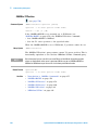
New features in version 5.20 of the InfiniiVision 5000 Series oscilloscope
software are:
• Mask testing, enabled with Option LMT.
• Tracking cursors (markers) have been added.
• Measurement statistics have been added.
• Labels can now be up to 10 characters.
More detailed descriptions of the new and changed commands appear
below.
New Commands
Command
Description
:ACQuire:SEGMented:ANALyze (see page 185)
Calculates measurement statistics and/or
infinite persistence over all segments that have
been acquired.
:CALibrate:OUTPut (see page 197)
Selects the signal output on the rear panel
TRIG OUT BNC.
:HARDcopy:LAYout (see page 267)
Sets the hardcopy layout mode.
:MEASure:RESults (see page 309)
Returns measurement statistics values.
:MEASure:STATistics (see page 317)
Sets the type of measurement statistics to
return.
:MEASure:STATistics:INCRement (see
page 318)
Updates the statistics once (incrementing the
count by one) using the current measurement
values.
:MEASure:STATistics:RESet (see page 319)
Resets the measurement statistics values.
:MTEenable (Mask Test Event Enable Register)
(see page 155)
Sets a mask in the Mask Test Event Enable
register.
:MTERegister[:EVENt] (Mask Test Event Event
Register) (see page 157)
Returns the integer value contained in the
Mask Test Event Event Register and clears the
register.
:MTESt Commands (see page 337)
Commands and queries to control the mask
test (Option LMT) features.
:RECall:MASK[:STARt] (see page 387)
Recalls a mask.
:SAVE:MASK[:STARt] (see page 387)
Saves the current mask.
:SAVE:WAVeform:SEGMented (see page 393)
Specifies which segments are included when
the waveform is saved.
:TRIGger:UART:BASE (see page 572)
Selects the front panel UART/RS232 trigger
setup data selection option from HEX or
BINary.
Agilent InfiniiVision 5000 Series Oscilloscopes Programmer's Guide
27
1
What's New
Changed
Commands
Obsolete
Commands
28
Command
Differences
:CHANnel<n>:LABel (see page 211)
Labels can now be up to 10 characters.
:DISPlay:LABList (see page 229)
Labels can now be up to 10 characters.
:MARKer:MODE (see page 276)
You can now select the WAVeform tracking
cursors mode.
:RECall:PWD (see page 375)
You can set the present working directory in
addition to querying for this information.
:SAVE:IMAGe[:STARt] (see page 380)
The file extension specified will change the
:SAVE:IMAGe:FORMat setting if it is a valid
image file extension.
:SAVE:PWD (see page 388)
You can set the present working directory in
addition to querying for this information.
:SAVE:WAVeform[:STARt] (see page 380)
The file extension specified will change the
:SAVE:WAVeform:FORMat setting if it is a valid
waveform file extension.
:TRIGger:CAN:SIGNal:BAUDrate (see
page 459)
The baud rate value can now be set in 100 b/s
increments.
:TRIGger:LIN:SIGNal:BAUDrate (see page 535)
The baud rate value can now be set in 100 b/s
increments.
:TRIGger:UART:BAUDrate (see page 573)
The baud rate value can now be set in 100 b/s
increments and the maximum baud rate is now
3 Mb/s.
:TRIGger:UART:DATA (see page 576)
You can now specify the data value using a
quoted ASCII character.
Obsolete Command
Current Command Equivalent
:MTESt:AMASk:{SAVE |
STORe} (see page 693)
:SAVE:MASK[:STARt] (see
page 387)
:MTESt:AVERage (see
page 694)
:ACQuire:TYPE AVERage (see
page 191)
:MTESt:AVERage:COUNt (see
page 695)
:ACQuire:COUNt (see
page 181)
:MTESt:LOAD (see page 696)
:RECall:MASK[:STARt] (see
page 374)
:MTESt:RUMode (see
page 697)
:MTESt:RMODe (see
page 356)
:MTESt:RUMode:SOFailure
(see page 698)
:MTESt:RMODe:FACTion:STO
P (see page 360)
Behavior Differences
Agilent InfiniiVision 5000 Series Oscilloscopes Programmer's Guide
What's New
Obsolete Command
Current Command Equivalent
:MTESt:{STARt | STOP} (see
page 699)
:RUN (see page 170) or :STOP
(see page 174)
:MTESt:TRIGger:SOURce (see
page 700)
:TRIGger Commands (see
page 440)
Agilent InfiniiVision 5000 Series Oscilloscopes Programmer's Guide
1
Behavior Differences
There are various commands
for setting the source with
different types of triggers.
29
1
What's New
What's New in Version 5.15
New features in version 5.15 of the InfiniiVision 5000 Series oscilloscope
software are:
• Waveform math can be performed using channels 3 and 4, and there is
a new ADD operator.
• Ratio of AC RMS values measurement.
• Analog channel impedance protection lock.
More detailed descriptions of the new and changed commands appear
below.
New Commands
30
Command
Description
:FUNCtion:GOFT:OPERation (see page 248)
Selects the math operation for the internal g(t)
source that can be used as the input to the FFT,
INTegrate, DIFFerentiate, and SQRT functions.
:FUNCtion:GOFT:SOURce1 (see page 249)
Selects the first input channel for the g(t)
source.
:FUNCtion:GOFT:SOURce2 (see page 250)
Selects the second input channel for the g(t)
source.
:FUNCtion:SOURce1 (see page 256)
Selects the first source for the ADD, SUBTract,
and MULTiply arithmetic operations or the
single source for the FFT, INTegrate,
DIFFerentiate, and SQRT functions.
:FUNCtion:SOURce2 (see page 257)
Selects the second input channel for the ADD,
SUBTract, and MULTiply arithmetic operations.
:MEASure:VRATio (see page 330)
Measures and returns the ratio of AC RMS
values of the specified sources expressed in
dB.
:SYSTem:PROTection:LOCK (see page 425)
Disables/enables the fifty ohm input
impedance setting.
Agilent InfiniiVision 5000 Series Oscilloscopes Programmer's Guide
What's New
Changed
Commands
Obsolete
Commands
Command
Differences
:ACQuire:COUNt (see page 181)
The :ACQuire:COUNt 1 command has been
deprecated. The AVERage acquisition type with
a count of 1 is functionally equivalent to the
HRESolution acquisition type; however, you
should select the high-resolution acquisition
mode with the :ACQuire:TYPE HRESolution
command instead.
:FUNCtion:OPERation (see page 252)
The ADD parameter is new, and now that
waveform math can be performed using
channels 3 and 4, this command selects the
operation only.
:FUNCtion:WINDow (see page 259)
You can now select the Blackman-Harris FFT
window.
Obsolete Command
Current Command Equivalent
Behavior Differences
:FUNCtion:SOURce (see
page 670)
:FUNCtion:SOURce1 (see
page 256)
Obsolete command has ADD,
SUBTract, and MULTiply
parameters; current command
has GOFT parameter.
Agilent InfiniiVision 5000 Series Oscilloscopes Programmer's Guide
1
31
1
What's New
What's New in Version 5.10
New features in version 5.10 of the InfiniiVision 5000 Series oscilloscope
software are:
• Segmented memory acquisition mode, enabled with Option SGM.
More detailed descriptions of the new and changed commands appear
below.
New Commands
Changed
Commands
Discontinued
Commands
32
Command
Description
:ACQuire:SEGMented:COUNt (see page 186)
Sets the number of memory segments.
:ACQuire:SEGMented:INDex (see page 187)
Selects the segmented memory index.
:WAVeform:SEGMented:COUNt (see page 609)
Returns the number of segments in the
currently acquired waveform data.
:WAVeform:SEGMented:TTAG (see page 610)
Returns the time tag for the selected
segmented memory index.
Command
Differences
:ACQuire:MODE (see page 183)
You can now select the SEGMented memory
mode.
Discontinued Command
Current Command Equivalent
:DISPlay:FREeze
none
Comments
Agilent InfiniiVision 5000 Series Oscilloscopes Programmer's Guide
1
What's New
What's New in Version 5.00
New features in version 5.00 of the InfiniiVision 5000 Series oscilloscope
software are:
• Serial triggering and decode options are now available.
• The :SAVE and :RECall command subsystems.
• Changes to the :HARDcopy command subsystem to make a clearer
distinction between printing and save/recall functionality.
More detailed descriptions of the new and changed commands appear
below.
New Commands
Command
Description
:HARDcopy:STARt (see page 270)
Starts a print job.
:HARDcopy:APRinter (see page 263)
Sets the active printer.
:HARDcopy:AREA (see page 262)
Specifies the area of the display to print
(currently SCReen only).
:HARDcopy:INKSaver (see page 266)
Inverts screen colors to save ink when printing.
:HARDcopy:PRinter:LIST (see page 269)
Returns a list of the available printers.
:RECall Commands (see page 371)
Commands for recalling previously saved
oscilloscope setups and traces.
:SAVE Commands (see page 377)
Commands for saving oscilloscope setups and
traces, screen images, and data.
:SBUS Commands (see page 394)
Commands for controlling oscilloscope
functions associated with the serial decode
bus.
:TRIGger:CAN Commands (see page 452)
Commands for triggering on Controller Area
Network (CAN) version 2.0A and 2.0B signals.
:TRIGger:IIC Commands (see page 518)
Commands for triggering on Inter-IC (IIC)
signals.
:TRIGger:LIN Commands (see page 527)
Commands for triggering on Local Interconnect
Network (LIN) signals.
:TRIGger:SPI Commands (see page 555)
Commands for triggering on Serial Peripheral
Interface (SPI) signals.
:TRIGger:UART Commands (see page 570)
Commands for triggering on UART/RS-232
signals.
:WAVeform:SOURce:SUBSource (see
page 615)
Selects subsource when :WAVeform:SOURce
is SBUS (serial decode).
Agilent InfiniiVision 5000 Series Oscilloscopes Programmer's Guide
33
1
What's New
Changed
Commands
Obsolete
Commands
34
Command
Differences
:BLANk (see page 144)
Now, you can also use this command with the
serial decode bus.
:DIGitize (see page 146)
Now, you can also use this command with the
serial decode bus.
:STATus (see page 173)
Now, you can also use this command with the
serial decode bus.
:TRIGger:MODE (see page 447)
You can now select the serial triggering modes.
:VIEW (see page 176)
Now, you can now use this command with the
serial decode bus.
:WAVeform:SOURce (see page 611)
Now, you can also use this command with the
serial decode bus.
Obsolete Command
Current Command Equivalent
:HARDcopy:FILename (see
page 674)
:RECall:FILename (see
page 372)
:SAVE:FILename (see
page 372)
:HARDcopy:FORMat (see
page 675)
:HARDcopy:APRinter (see
page 263)
:SAVE:IMAGe:FORMat (see
page 383)
:SAVE:WAVeform:FORMat
(see page 391)
:HARDcopy:IGColors (see
page 677)
:HARDcopy:INKSaver (see
page 266)
:HARDcopy:PDRiver (see
page 678)
:HARDcopy:APRinter (see
page 263)
Behavior Differences
Agilent InfiniiVision 5000 Series Oscilloscopes Programmer's Guide
1
What's New
What's New in Version 4.10
New features in version 4.10 of the InfiniiVision 5000 Series oscilloscope
software are:
• The square root waveform math function.
• Several new hardcopy printer drivers.
More detailed descriptions of the new and changed commands appear
below.
Changed
Commands
Command
Differences
:FUNCtion:OPERation (see page 252)
You can now select the SQRT (square root)
waveform math function.
:HARDcopy:PDRiver (see page 678)
You can now select the new DJPR0kx50,
DJ55xx, PS470, and LJFastraster printer
drivers.
Agilent InfiniiVision 5000 Series Oscilloscopes Programmer's Guide
35
1
What's New
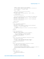
Version 4.00 at Introduction
The Agilent InfiniiVision 5000 Series oscilloscopes were introduced with
version 4.00 of oscilloscope operating software. The command set is
similar to the 6000 Series oscilloscopes (and the 54620/54640 Series
oscilloscopes before them) except that digital channels, rear- panel 10 Mhz
reference BNC input/output, and serial bus triggering/decode features are
not present.
36
Agilent InfiniiVision 5000 Series Oscilloscopes Programmer's Guide
Agilent InfiniiVision 5000 Series Oscilloscopes
Programmer's Guide
2
Setting Up
Step 1. Install Agilent IO Libraries Suite software 38
Step 2. Connect and set up the oscilloscope 39
Step 3. Verify the oscilloscope connection 41
This chapter explains how to install the Agilent IO Libraries Suite
software, connect the oscilloscope to the controller PC, set up the
oscilloscope, and verify the oscilloscope connection.
37
2
Setting Up
Step 1. Install Agilent IO Libraries Suite software
Insert the Automation- Ready CD that was shipped with your oscilloscope
into the controller PC's CD- ROM drive, and follow its installation
instructions.
You can also download the Agilent IO Libraries Suite software from the
web at:
• "http://www.agilent.com/find/iolib"
38
Agilent InfiniiVision 5000 Series Oscilloscopes Programmer's Guide
2
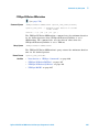
Setting Up
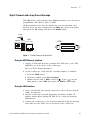
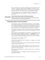
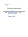
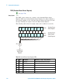
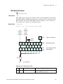
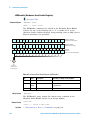
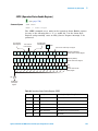
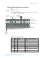
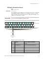
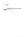
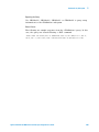
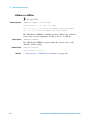
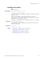
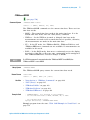
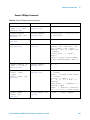
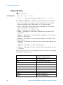
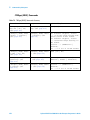
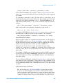
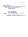
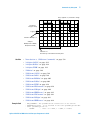
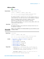
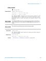
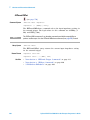
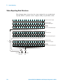
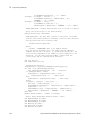
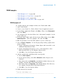
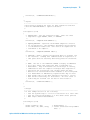
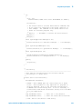
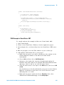
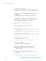
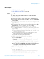
Step 2. Connect and set up the oscilloscope
The 5000 Series oscilloscope has three different interfaces you can use for
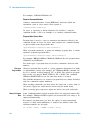
programming: USB (device), LAN, or GPIB.
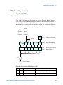
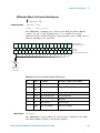
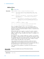
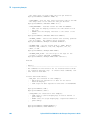
All three interfaces are "live" by default, but you can turn them off if
desired. To access these settings press the Utility key on the front panel,
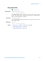
then press the I/O softkey, then press the Control softkey.
USB
DEVICE HOST
LAN
NON-AUTO-MDIX
Figure 1
GPIB
Control Connectors on Rear Panel
Using the USB (Device) Interface
1 Connect a USB cable from the controller PC's USB port to the "USB
DEVICE" port on the back of the oscilloscope.
This is a USB 2.0 high- speed port.
2 On the oscilloscope, verify that the controller interface is enabled:
a Press the Utility button.
b Using the softkeys, press I/O and Control.
c Ensure the box next to USB is selected (
). If not ( ), use the
Entry knob to select USB; then, press the Control softkey again.
Using the LAN Interface
1 If the controller PC isn't already connected to the local area network
(LAN), do that first.
2 Get the oscilloscope's network parameters (hostname, domain, IP
address, subnet mask, gateway IP, DNS IP, etc.) from your network
administrator.
3 Connect the oscilloscope to the local area network (LAN) by inserting
LAN cable into the "LAN" port on the back of the oscilloscope.
Agilent InfiniiVision 5000 Series Oscilloscopes Programmer's Guide
39
2
Setting Up
4 On the oscilloscope, verify that the controller interface is enabled:
a Press the Utility button.
b Using the softkeys, press I/O and Control.
c Ensure the box next to LAN is selected (
). If not ( ), use the
Entry knob to select LAN; then, press the Control softkey again.
5 Configure the oscilloscope's LAN interface:
a Press the Configure softkey until "LAN" is selected.
b Press the LAN Settings softkey.
c Press the Addresses softkey. Use the IP Options softkey and the Entry
knob to select DHCP, AutoIP, or netBIOS. Use the Modify softkey (and
the other softkeys and the Entry knob) to enter the IP Address,
Subnet Mask, Gateway IP, and DNS IP values. When you are done,
press the return (up arrow) softkey.
d Press the Domain softkey. Use the Modify softkey (and the other
softkeys and the Entry knob) to enter the Host name and the
Domain name. When you are done, press the return (up arrow)
softkey.
Using the GPIB Interface
1 Connect a GPIB cable from the controller PC's GPIB interface to the
"GPIB" port on the back of the oscilloscope.
2 On the oscilloscope, verify that the controller interface is enabled:
a Press the Utility button.
b Using the softkeys, press I/O and Control.
c Use the Entry knob to select "GPIB"; then, press the Control softkey
again.
Ensure the box next to GPIB is selected ( ). If not ( ), use the
Entry knob to select GPIB; then, press the Control softkey again.
3 Configure the oscilloscope's GPIB interface:
a Press the Configure softkey until "GPIB" is selected.
b Use the Entry knob to select the Address value.
40
Agilent InfiniiVision 5000 Series Oscilloscopes Programmer's Guide
Setting Up
2
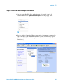
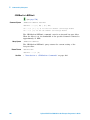
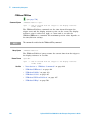
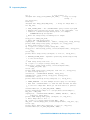
Step 3. Verify the oscilloscope connection
1 On the controller PC, click on the Agilent IO Control icon in the
taskbar and choose Agilent Connection Expert from the popup menu.
2 In the Agilent Connection Expert application, instruments connected to
the controller's USB and GPIB interfaces should automatically appear.
(You can click Refresh All to update the list of instruments on these
interfaces.)
Agilent InfiniiVision 5000 Series Oscilloscopes Programmer's Guide
41
2
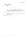
Setting Up
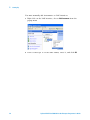
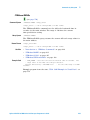
You must manually add instruments on LAN interfaces:
a Right- click on the LAN interface, choose Add Instrument from the
popup menu
b If the oscilloscope is on the same subnet, select it, and click OK.
42
Agilent InfiniiVision 5000 Series Oscilloscopes Programmer's Guide
2
Setting Up
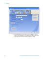
Otherwise, if the instrument is not on the same subnet, click Add
Address.
i
In the next dialog, select either Hostname or IP address, and enter
the oscilloscope's hostname or IP address.
ii Click Test Connection.
Agilent InfiniiVision 5000 Series Oscilloscopes Programmer's Guide
43
2
Setting Up
iii If the instrument is successfully opened, click OK to close the
dialog. If the instrument is not opened successfully, go back and
verify the LAN connections and the oscilloscope setup.
44
Agilent InfiniiVision 5000 Series Oscilloscopes Programmer's Guide
2
Setting Up
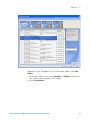
3 Test some commands on the instrument:
a Right- click on the instrument and choose Send Commands To This
Instrument from the popup menu.
b In the Agilent Interactive IO application, enter commands in the
Command field and press Send Command, Read Response, or Send&Read.
c Choose Connect>Exit from the menu to exit the Agilent Interactive IO
application.
4 In the Agilent Connection Expert application, choose File>Exit from the
menu to exit the application.
Agilent InfiniiVision 5000 Series Oscilloscopes Programmer's Guide
45
2
46
Setting Up
Agilent InfiniiVision 5000 Series Oscilloscopes Programmer's Guide
Agilent InfiniiVision 5000 Series Oscilloscopes
Programmer's Guide
3
Getting Started
Basic Oscilloscope Program Structure 48
Programming the Oscilloscope 50
Other Ways of Sending Commands 59
This chapter gives you an overview of programming the 5000 Series
oscilloscopes. It describes basic oscilloscope program structure and shows
how to program the oscilloscope using a few simple examples.
The getting started examples show how to send oscilloscope setup, data
capture, and query commands, and they show how to read query results.
NOTE
Language for Program Examples
The programming examples in this guide are written in Visual Basic using the Agilent VISA
COM library.
47
3
Getting Started
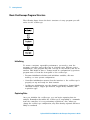
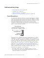
Basic Oscilloscope Program Structure
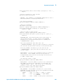
The following figure shows the basic structure of every program you will
write for the oscilloscope.
Initializing
To ensure consistent, repeatable performance, you need to start the
program, controller, and oscilloscope in a known state. Without correct
initialization, your program may run correctly in one instance and not in
another. This might be due to changes made in configuration by previous
program runs or from the front panel of the oscilloscope.
• Program initialization defines and initializes variables, allocates
memory, or tests system configuration.
• Controller initialization ensures that the interface to the oscilloscope is
properly set up and ready for data transfer.
• Oscilloscope initialization sets the channel configuration, channel labels,
threshold voltages, trigger specification, trigger mode, timebase, and
acquisition type.
Capturing Data
Once you initialize the oscilloscope, you can begin capturing data for
analysis. Remember that while the oscilloscope is responding to commands
from the controller, it is not performing acquisitions. Also, when you
change the oscilloscope configuration, any data already captured will most
likely be rendered.
48
Agilent InfiniiVision 5000 Series Oscilloscopes Programmer's Guide
Getting Started
3
To collect data, you use the :DIGitize command. This command clears the
waveform buffers and starts the acquisition process. Acquisition continues
until acquisition memory is full, then stops. The acquired data is displayed
by the oscilloscope, and the captured data can be measured, stored in
trace memory in the oscilloscope, or transferred to the controller for
further analysis. Any additional commands sent while :DIGitize is working
are buffered until :DIGitize is complete.
You could also put the oscilloscope into run mode, then use a wait loop in
your program to ensure that the oscilloscope has completed at least one
acquisition before you make a measurement. Agilent does not recommend
this because the needed length of the wait loop may vary, causing your
program to fail. :DIGitize, on the other hand, ensures that data capture is
complete. Also, :DIGitize, when complete, stops the acquisition process so
that all measurements are on displayed data, not on a constantly changing
data set.
Analyzing Captured Data
After the oscilloscope has completed an acquisition, you can find out more
about the data, either by using the oscilloscope measurements or by
transferring the data to the controller for manipulation by your program.
Built- in measurements include: frequency, duty cycle, period, positive
pulse width, and negative pulse width.
Using the :WAVeform commands, you can transfer the data to your
controller. You may want to display the data, compare it to a known good
measurement, or simply check logic patterns at various time intervals in
the acquisition.
Agilent InfiniiVision 5000 Series Oscilloscopes Programmer's Guide
49
3
Getting Started
Programming the Oscilloscope
• "Referencing the IO Library" on page 50
• "Opening the Oscilloscope Connection via the IO Library" on page 51
• "Using :AUToscale to Automate Oscilloscope Setup" on page 52
• "Using Other Oscilloscope Setup Commands" on page 52
• "Capturing Data with the :DIGitize Command" on page 53
• "Reading Query Responses from the Oscilloscope" on page 55
• "Reading Query Results into String Variables" on page 56
• "Reading Query Results into Numeric Variables" on page 56
• "Reading Definite- Length Block Query Response Data" on page 56
• "Sending Multiple Queries and Reading Results" on page 57
• "Checking Instrument Status" on page 58
Referencing the IO Library
No matter which instrument programming library you use (SICL, VISA, or
VISA COM), you must reference the library from your program.
In C/C++, you must tell the compiler where to find the include and library
files (see the Agilent IO Libraries Suite documentation for more
information).
To reference the Agilent VISA COM library in Visual Basic for Applications
(VBA, which comes with Microsoft Office products like Excel):
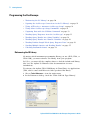
1 Choose Tools>References... from the main menu.
2 In the References dialog, check the "VISA COM 3.0 Type Library".
50
Agilent InfiniiVision 5000 Series Oscilloscopes Programmer's Guide
3
Getting Started
3 Click OK.
To reference the Agilent VISA COM library in Microsoft Visual Basic 6.0:
1 Choose Project>References... from the main menu.
2 In the References dialog, check the "VISA COM 3.0 Type Library".
3 Click OK.
Opening the Oscilloscope Connection via the IO Library
PC controllers communicate with the oscilloscope by sending and receiving
messages over a remote interface. Once you have opened a connection to
the oscilloscope over the remote interface, programming instructions
normally appear as ASCII character strings embedded inside write
statements of the programing language. Read statements are used to read
query responses from the oscilloscope.
For example, when using the Agilent VISA COM library in Visual Basic
(after opening the connection to the instrument using the
ResourceManager object's Open method), the FormattedIO488 object's
WriteString, WriteNumber, WriteList, or WriteIEEEBlock methods are used
for sending commands and queries. After a query is sent, the response is
read using the ReadString, ReadNumber, ReadList, or ReadIEEEBlock
methods.
The following Visual Basic statements open the connection and send a
command that turns on the oscilloscope's label display.
Dim myMgr As VisaComLib.ResourceManager
Dim myScope As VisaComLib.FormattedIO488
Set myMgr = New VisaComLib.ResourceManager
Set myScope = New VisaComLib.FormattedIO488
' Open the connection to the oscilloscope. Get the VISA Address from the
' Agilent Connection Expert (installed with Agilent IO Libraries Suite).
Set myScope.IO = myMgr.Open("<VISA Address>")
' Send a command.
myScope.WriteString ":DISPlay:LABel ON"
The ":DISPLAY:LABEL ON" in the above example is called a program
message. Program messages are explained in more detail in "Program
Message Syntax" on page 751.
Initializing the Interface and the Oscilloscope
To make sure the bus and all appropriate interfaces are in a known state,
begin every program with an initialization statement. When using the
Agilent VISA COM library, you can use the resource session object's Clear
method to clears the interface buffer:
Agilent InfiniiVision 5000 Series Oscilloscopes Programmer's Guide
51
3
Getting Started
Dim myMgr As VisaComLib.ResourceManager
Dim myScope As VisaComLib.FormattedIO488
Set myMgr = New VisaComLib.ResourceManager
Set myScope = New VisaComLib.FormattedIO488
' Open the connection to the oscilloscope. Get the VISA Address from the
' Agilent Connection Expert (installed with Agilent IO Libraries Suite).
Set myScope.IO = myMgr.Open("<VISA Address>")
' Clear the interface buffer.
myScope.IO.Clear
When you are using GPIB, CLEAR also resets the oscilloscope's parser. The
parser is the program which reads in the instructions which you send it.
After clearing the interface, initialize the instrument to a preset state:
myScope.WriteString "*RST"
NOTE
Information for Initializing the Instrument
The actual commands and syntax for initializing the instrument are discussed in "Common
(*) Commands" on page 111.
Refer to the Agilent IO Libraries Suite documentation for information on initializing the
interface.
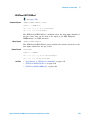
Using :AUToscale to Automate Oscilloscope Setup
The :AUToscale command performs a very useful function for unknown
waveforms by setting up the vertical channel, time base, and trigger level
of the instrument.
The syntax for the autoscale command is:
myScope.WriteString ":AUToscale"
Using Other Oscilloscope Setup Commands
A typical oscilloscope setup would set the vertical range and offset voltage,
the horizontal range, delay time, delay reference, trigger mode, trigger
level, and slope. An example of the commands that might be sent to the
oscilloscope are:
myScope.WriteString
myScope.WriteString
myScope.WriteString
myScope.WriteString
myScope.WriteString
myScope.WriteString
52
":CHANnel1:PROBe 10"
":CHANnel1:RANGe 16"
":CHANnel1:OFFSet 1.00"
":TIMebase:MODE MAIN"
":TIMebase:RANGe 1E-3"
":TIMebase:DELay 100E-6"
Agilent InfiniiVision 5000 Series Oscilloscopes Programmer's Guide
Getting Started
3
Vertical is set to 16 V full- scale (2 V/div) with center of screen at 1 V and
probe attenuation set to 10. This example sets the time base at 1 ms
full- scale (100 ms/div) with a delay of 100 µs.
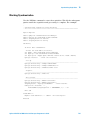
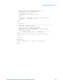
Example Oscilloscope Setup Code
This program demonstrates the basic command structure used to program
the oscilloscope.
' Initialize the instrument interface to a known state.
myScope.IO.Clear
' Initialize the instrument to a preset state.
myScope.WriteString "*RST"
' Set the time base mode to normal with the horizontal time at
' 50 ms/div with 0 s of delay referenced at the center of the
' graticule.
myScope.WriteString ":TIMebase:RANGe 5E-4"
' Time base to 50 us/div.
myScope.WriteString ":TIMebase:DELay 0"
' Delay to zero.
myScope.WriteString ":TIMebase:REFerence CENTer"
' Display ref. at
' center.
' Set the vertical range to 1.6 volts full scale with center screen
' at -0.4 volts with 10:1 probe attenuation and DC coupling.
myScope.WriteString ":CHANnel1:PROBe 10"
' Probe attenuation
' to 10:1.
myScope.WriteString ":CHANnel1:RANGe 1.6"
' Vertical range
' 1.6 V full scale.
myScope.WriteString ":CHANnel1:OFFSet -.4"
' Offset to -0.4.
myScope.WriteString ":CHANnel1:COUPling DC" ' Coupling to DC.
' Configure the instrument to trigger at -0.4 volts with normal
' triggering.
myScope.WriteString ":TRIGger:SWEep NORMal" ' Normal triggering.
myScope.WriteString ":TRIGger:LEVel -.4"
' Trigger level to -0.4.
myScope.WriteString ":TRIGger:SLOPe POSitive" ' Trigger on pos. slope.
' Configure the instrument for normal acquisition.
myScope.WriteString ":ACQuire:TYPE NORMal"
' Normal acquisition.
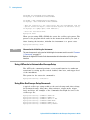
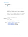
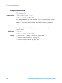
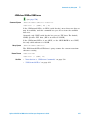
Capturing Data with the :DIGitize Command
The :DIGitize command captures data that meets the specifications set up
by the :ACQuire subsystem. When the digitize process is complete, the
acquisition is stopped. The captured data can then be measured by the
instrument or transferred to the controller for further analysis. The
captured data consists of two parts: the waveform data record, and the
preamble.
Agilent InfiniiVision 5000 Series Oscilloscopes Programmer's Guide
53
3
Getting Started
NOTE
Ensure New Data is Collected
When you change the oscilloscope configuration, the waveform buffers are cleared. Before
doing a measurement, send the :DIGitize command to the oscilloscope to ensure new data
has been collected.
When you send the :DIGitize command to the oscilloscope, the specified
channel signal is digitized with the current :ACQuire parameters. To obtain
waveform data, you must specify the :WAVeform parameters for the
SOURce channel, the FORMat type, and the number of POINts prior to
sending the :WAVeform:DATA? query.
NOTE
Set :TIMebase:MODE to MAIN when using :DIGitize
:TIMebase:MODE must be set to MAIN to perform a :DIGitize command or to perform any
:WAVeform subsystem query. A "Settings conflict" error message will be returned if these
commands are executed when MODE is set to ROLL, XY, or WINDow (zoomed). Sending the
*RST (reset) command will also set the time base mode to normal.
The number of data points comprising a waveform varies according to the
number requested in the :ACQuire subsystem. The :ACQuire subsystem
determines the number of data points, type of acquisition, and number of
averages used by the :DIGitize command. This allows you to specify exactly
what the digitized information contains.
The following program example shows a typical setup:
myScope.WriteString
myScope.WriteString
myScope.WriteString
myScope.WriteString
myScope.WriteString
myScope.WriteString
myScope.WriteString
myScope.WriteString
":ACQuire:TYPE AVERage"
":ACQuire:COMPlete 100"
":ACQuire:COUNt 8"
":DIGitize CHANnel1"
":WAVeform:SOURce CHANnel1"
":WAVeform:FORMat BYTE"
":WAVeform:POINts 500"
":WAVeform:DATA?"
This setup places the instrument into the averaged mode with eight
averages. This means that when the :DIGitize command is received, the
command will execute until the signal has been averaged at least eight
times.
After receiving the :WAVeform:DATA? query, the instrument will start
passing the waveform information.
Digitized waveforms are passed from the instrument to the controller by
sending a numerical representation of each digitized point. The format of
the numerical representation is controlled with the :WAVeform:FORMat
command and may be selected as BYTE, WORD, or ASCii.
54
Agilent InfiniiVision 5000 Series Oscilloscopes Programmer's Guide
3
Getting Started
The easiest method of transferring a digitized waveform depends on data
structures, formatting available and I/O capabilities. You must scale the
integers to determine the voltage value of each point. These integers are
passed starting with the left most point on the instrument's display.
For more information, see the waveform subsystem commands and
corresponding program code examples in ":WAVeform Commands" on
page 590.
NOTE
Aborting a Digitize Operation Over the Programming Interface
When using the programming interface, you can abort a digitize operation by sending a
Device Clear over the bus (for example, myScope.IO.Clear).
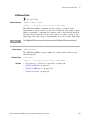
Reading Query Responses from the Oscilloscope
After receiving a query (command header followed by a question mark),
the instrument interrogates the requested function and places the answer
in its output queue. The answer remains in the output queue until it is
read or another command is issued. When read, the answer is transmitted
across the interface to the designated listener (typically a controller).
The statement for reading a query response message from an instrument's
output queue typically has a format specification for handling the response
message.
When using the VISA COM library in Visual Basic, you use different read
methods (ReadString, ReadNumber, ReadList, or ReadIEEEBlock) for the
various query response formats. For example, to read the result of the
query command :CHANnel1:COUPling? you would execute the statements:
myScope.WriteString ":CHANnel1:COUPling?"
Dim strQueryResult As String
strQueryResult = myScope.ReadString
This reads the current setting for the channel one coupling into the string
variable strQueryResult.
All results for queries (sent in one program message) must be read before
another program message is sent.
Sending another command before reading the result of the query clears
the output buffer and the current response. This also causes an error to
be placed in the error queue.
Executing a read statement before sending a query causes the controller to
wait indefinitely.
The format specification for handling response messages depends on the
programming language.
Agilent InfiniiVision 5000 Series Oscilloscopes Programmer's Guide
55
3
Getting Started
Reading Query Results into String Variables
The output of the instrument may be numeric or character data depending
on what is queried. Refer to the specific command descriptions in
Chapter 5, “Commands by Subsystem,” starting on page 109 for the
formats and types of data returned from queries.
NOTE
Express String Variables Using Exact Syntax
In Visual Basic, string variables are case sensitive and must be expressed exactly the same
each time they are used.
The following example shows numeric data being returned to a string
variable:
myScope.WriteString ":CHANnel1:RANGe?"
Dim strQueryResult As String
strQueryResult = myScope.ReadString
MsgBox "Range (string):" + strQueryResult
After running this program, the controller displays:
Range (string): +40.0E+00
Reading Query Results into Numeric Variables
The following example shows numeric data being returned to a numeric
variable:
myScope.WriteString ":CHANnel1:RANGe?"
Dim varQueryResult As Variant
strQueryResult = myScope.ReadNumber
MsgBox "Range (variant):" + CStr(varQueryResult)
After running this program, the controller displays:
Range (variant): 40
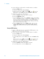
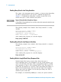
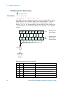
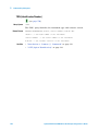
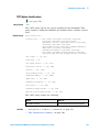
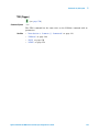
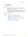
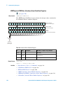
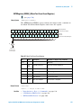
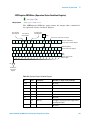
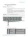
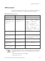
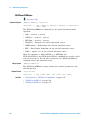
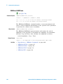
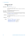
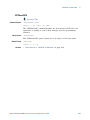
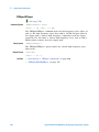
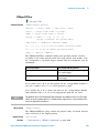
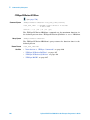
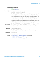
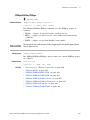
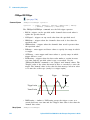
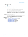
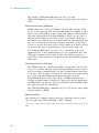
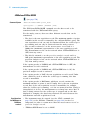
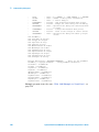
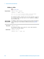
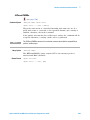
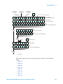
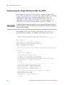
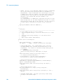
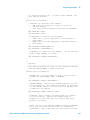
Reading Definite-Length Block Query Response Data
Definite- length block query response data allows any type of
device- dependent data to be transmitted over the system interface as a
series of 8- bit binary data bytes. This is particularly useful for sending
large quantities of data or 8- bit extended ASCII codes. The syntax is a
pound sign (#) followed by a non- zero digit representing the number of
digits in the decimal integer. After the non- zero digit is the decimal
integer that states the number of 8- bit data bytes being sent. This is
followed by the actual data.
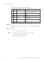
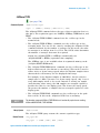
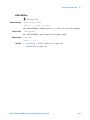
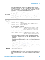
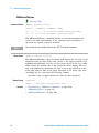
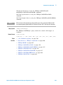
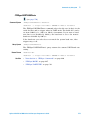
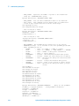
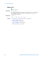
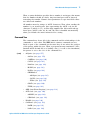
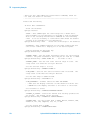
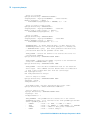
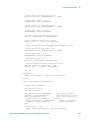
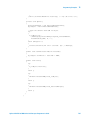
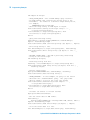
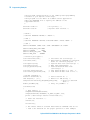
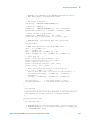
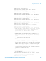
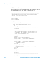
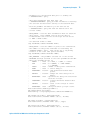
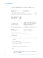
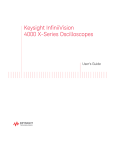
For example, for transmitting 1000 bytes of data, the syntax would be:
56
Agilent InfiniiVision 5000 Series Oscilloscopes Programmer's Guide
3
Getting Started
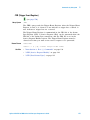
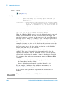
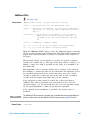
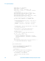
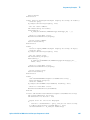
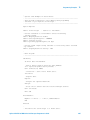
/TLADQNE%HFHSR
5G@S'NKKNV
"BST@K%@S@
AXSDRNEC@S@SDQLHM@SNQ
/TLADQNE#XSDR
SNAD5Q@MRLHSSDC
Figure 2
Definite-length block response data
The "8" states the number of digits that follow, and "00001000" states the
number of bytes to be transmitted.
The VISA COM library's ReadIEEEBlock and WriteIEEEBlock methods
understand the definite- length block syntax, so you can simply use
variables that contain the data:
' Read oscilloscope setup using ":SYSTem:SETup?" query.
myScope.WriteString ":SYSTem:SETup?"
Dim varQueryResult As Variant
varQueryResult = myScope.ReadIEEEBlock(BinaryType_UI1)
' Write learn string back to oscilloscope using ":SYSTem:SETup" command:
myScope.WriteIEEEBlock ":SYSTem:SETup ", varQueryResult
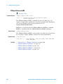
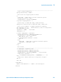
Sending Multiple Queries and Reading Results
You can send multiple queries to the instrument within a single command
string, but you must also read them back as a single query result. This can
be accomplished by reading them back into a single string variable,
multiple string variables, or multiple numeric variables.
For example, to read the :TIMebase:RANGe?;DELay? query result into a
single string variable, you could use the commands:
myScope.WriteString ":TIMebase:RANGe?;DELay?"
Dim strQueryResult As String
strQueryResult = myScope.ReadString
MsgBox "Timebase range; delay:" + strQueryResult
When you read the result of multiple queries into a single string variable,
each response is separated by a semicolon. For example, the output of the
previous example would be:
Timebase range; delay: <range_value>;<delay_value>
To read the :TIMebase:RANGe?;DELay? query result into multiple string
variables, you could use the ReadList method to read the query results
into a string array variable using the commands:
myScope.WriteString ":TIMebase:RANGe?;DELay?"
Dim strResults() As String
Agilent InfiniiVision 5000 Series Oscilloscopes Programmer's Guide
57
3
Getting Started
strResults() = myScope.ReadList(ASCIIType_BSTR)
MsgBox "Timebase range: " + strResults(0) + ", delay: " + strResults(1)
To read the :TIMebase:RANGe?;DELay? query result into multiple numeric
variables, you could use the ReadList method to read the query results
into a variant array variable using the commands:
myScope.WriteString ":TIMebase:RANGe?;DELay?"
Dim varResults() As Variant
varResults() = myScope.ReadList
MsgBox "Timebase range: " + FormatNumber(varResults(0) * 1000, 4) + _
" ms, delay: " + FormatNumber(varResults(1) * 1000000, 4) + " us"
Checking Instrument Status
Status registers track the current status of the instrument. By checking
the instrument status, you can find out whether an operation has been
completed, whether the instrument is receiving triggers, and more.
For more information, see Chapter 9, “Status Reporting,” starting on page
715 which explains how to check the status of the instrument.
58
Agilent InfiniiVision 5000 Series Oscilloscopes Programmer's Guide
Getting Started
3
Other Ways of Sending Commands
Standard Commands for Programmable Instrumentation (SCPI) can be sent
via a Telnet socket or through the Browser Web Control.
Telnet Sockets
The following information is provided for programmers who wish to
control the oscilloscope with SCPI commands in a Telnet session.
To connect to the oscilloscope via a telnet socket, issue the following
command:
telnet <hostname> 5024
where <hostname> is the hostname of the oscilloscope. This will give you a
command line with prompt.
For a command line without a prompt, use port 5025. For example:
telnet <hostname> 5025
Sending SCPI Commands Using Browser Web Control
To send SCPI commands using the Browser Web Control feature, establish
a connection to the oscilloscope via LAN as described in the 5000 Series
Oscilloscopes User's Guide. When you make the connection to the
oscilloscope via LAN and the instrument's welcome page is displayed,
select the Browser Web Control tab, then select the Remote Programming link.
Agilent InfiniiVision 5000 Series Oscilloscopes Programmer's Guide
59
3
60
Getting Started
Agilent InfiniiVision 5000 Series Oscilloscopes Programmer's Guide
Agilent InfiniiVision 5000 Series Oscilloscopes
Programmer's Guide
4
Commands Quick Reference
Command Summary 62
Syntax Elements 106
61
4
Commands Quick Reference
Command Summary
Table 2
Common (*) Commands Summary
Command
Query
Options and Query Returns
*CLS (see page 115)
n/a
n/a
*ESE <mask> (see
page 116)
*ESE? (see page 117)
<mask> ::= 0 to 255; an integer
in NR1 format:
Bit Weight Name Enables
--- ------ ---- ---------7
128 PON Power On
6
64 URQ User Request
5
32 CME Command Error
4
16 EXE Execution Error
3
8 DDE Dev. Dependent Error
2
4 QYE Query Error
1
2 RQL Request Control
0
1 OPC Operation Complete
n/a
*ESR? (see page 118)
<status> ::= 0 to 255; an integer
in NR1 format
n/a
*IDN? (see page 118)
AGILENT TECHNOLOGIES,<model>,
<serial number>,X.XX.XX
<model> ::= the model number of
the instrument
<serial number> ::= the serial
number of the instrument
<X.XX.XX> ::= the software
revision of the instrument
n/a
*LRN? (see page 121)
<learn_string> ::= current
instrument setup as a block of
data in IEEE 488.2 # format
*OPC (see page 122)
*OPC? (see page 122)
ASCII "1" is placed in the output
queue when all pending device
operations have completed.
62
Agilent InfiniiVision 5000 Series Oscilloscopes Programmer's Guide
4
Commands Quick Reference
Table 2
Common (*) Commands Summary (continued)
Command
Query
Options and Query Returns
n/a
*OPT? (see page 123)
<return_value> ::= 0,0,<license
info>
<license info> ::= <All field>,
<reserved>, <reserved>,
<reserved>, <reserved>,
<reserved>, <Low Speed Serial>,
<Automotive Serial>, <reserved>,
<Secure>, <reserved>,
<reserved>, <reserved>,
<reserved>,
<RS-232/UART Serial>,
<reserved>, <Segmented Memory>,
<Mask Test>, <reserved>,
<reserved>, <FlexRay
Conformance>, <reserved>,
<reserved>, <I2S Serial>,
<FlexRay Trigger/Decode>,
<reserved>, <reserved>, <MIL-STD
1553 Trigger/Decode>, <reserved>
<All field> ::= {0 | All}
<reserved> ::= 0
<Low Speed Serial> ::= {0 | LSS}
<Automotive Serial> ::= {0 | AMS}
<Secure> ::= {0 | SEC}
<RS-232/UART Serial> ::= {0 |
232}
<Segmented Memory> ::= {0 | SGM}
<Mask Test> ::= {0 | LMT}
<FlexRay Conformance> ::= {0 |
FRC}
<I2S Serial> ::= {0 | SND}
<FlexRay Trigger/Decode> ::= {0 |
FLX}
<MIL-STD 1553 Trigger/Decode>
::= {0 | 553}
*RCL <value> (see
page 124)
n/a
<value> ::= {0 | 1 | 2 | 3 | 4 |
5 | 6 | 7 | 8 | 9}
*RST (see page 125)
n/a
See *RST (Reset) (see page 125)
*SAV <value> (see
page 128)
n/a
<value> ::= {0 | 1 | 2 | 3 | 4 |
5 | 6 | 7 | 8 | 9}
Agilent InfiniiVision 5000 Series Oscilloscopes Programmer's Guide
63
4
Commands Quick Reference
Table 2
Common (*) Commands Summary (continued)
Command
Query
Options and Query Returns
*SRE <mask> (see
page 129)
*SRE? (see page 130)
<mask> ::= sum of all bits that
are set, 0 to 255; an integer in
NR1 format. <mask> ::= following
values:
Bit Weight Name Enables
--- ------ ---- ---------7
128 OPER Operation Status Reg
6
64 ---- (Not used.)
5
32 ESB Event Status Bit
4
16 MAV Message Available
3
8 ---- (Not used.)
2
4 MSG Message
1
2 USR User
0
1 TRG Trigger
n/a
*STB? (see page 131)
<value> ::= 0 to 255; an integer
in NR1 format, as shown in the
following:
Bit Weight Name "1" Indicates
--- ------ ---- --------------7
128 OPER Operation status
condition occurred.
6
64 RQS/ Instrument is
MSS requesting service.
5
32 ESB Enabled event status
condition occurred.
4
16 MAV Message available.
3
8 ---- (Not used.)
2
4 MSG Message displayed.
1
2 USR User event
condition occurred.
0
1 TRG A trigger occurred.
*TRG (see page 133)
n/a
n/a
n/a
*TST? (see page 134)
<result> ::= 0 or non-zero value;
an integer in NR1 format
*WAI (see page 135)
n/a
n/a
Table 3
Root (:) Commands Summary
Command
Query
Options and Query Returns
n/a
:AER? (see page 139)
{0 | 1}; an integer in NR1 format
:AUToscale
[<source>[,..,<source
>]] (see page 140)
n/a
<source> ::= CHANnel<n>
<source> can be repeated up to 5
times
<n> ::= 1-2 or 1-4 in NR1 format
64
Agilent InfiniiVision 5000 Series Oscilloscopes Programmer's Guide
4
Commands Quick Reference
Table 3
Root (:) Commands Summary (continued)
Command
Query
Options and Query Returns
:AUToscale:AMODE
<value> (see
page 142)
:AUToscale:AMODE?
(see page 142)
<value> ::= {NORMal | CURRent}}
:AUToscale:CHANnels
<value> (see
page 143)
:AUToscale:CHANnels?
(see page 143)
<value> ::= {ALL | DISPlayed}}
:BLANk [<source>]
(see page 144)
n/a
<source> ::= {CHANnel<n>} |
FUNCtion | MATH}
<n> ::= 1-2 or 1-4 in NR1 format
:CDISplay (see
page 145)
n/a
n/a
:DIGitize
[<source>[,..,<source
>]] (see page 146)
n/a
<source> ::= {CHANnel<n> |
FUNCtion | MATH}
<source> can be repeated up to 5
times
<n> ::= 1-2 or 1-4 in NR1 format
:HWEenable <n> (see
page 148)
:HWEenable? (see
page 148)
<n> ::= 16-bit integer in NR1
format
n/a
:HWERregister:CONDiti
on? (see page 150)
<n> ::= 16-bit integer in NR1
format
n/a
:HWERegister[:EVENt]?
(see page 152)
<n> ::= 16-bit integer in NR1
format
:MERGe <pixel memory>
(see page 154)
n/a
<pixel memory> ::= {PMEMory{0 | 1
| 2 | 3 | 4 | 5 | 6 | 7 | 8 | 9}}
:MTEenable <n> (see
page 155)
:MTEenable? (see
page 155)
<n> ::= 16-bit integer in NR1
format
n/a
:MTERegister[:EVENt]?
(see page 157)
<n> ::= 16-bit integer in NR1
format
:OPEE <n> (see
page 159)
:OPEE? (see page 160)
<n> ::= 16-bit integer in NR1
format
n/a
:OPERregister:CONDiti
on? (see page 161)
<n> ::= 16-bit integer in NR1
format
n/a
:OPERegister[:EVENt]?
(see page 163)
<n> ::= 16-bit integer in NR1
format
Agilent InfiniiVision 5000 Series Oscilloscopes Programmer's Guide
65
4
Commands Quick Reference
Table 3
Root (:) Commands Summary (continued)
Command
Query
Options and Query Returns
:OVLenable <mask>
(see page 165)
:OVLenable? (see
page 166)
<mask> ::= 16-bit integer in NR1
format as shown:
Bit Weight Input
--- ------ ---------10
1024 Ext Trigger Fault
9
512 Channel 4 Fault
8
256 Channel 3 Fault
7
128 Channel 2 Fault
6
64 Channel 1 Fault
4
16 Ext Trigger OVL
3
8 Channel 4 OVL
2
4 Channel 3 OVL
1
2 Channel 2 OVL
0
1 Channel 1 OVL
n/a
:OVLRegister? (see
page 167)
<value> ::= integer in NR1
format. See OVLenable for <value>
:PRINt [<options>]
(see page 169)
n/a
<options> ::= [<print
option>][,..,<print option>]
<print option> ::= {COLor |
GRAYscale | PRINter0 | BMP8bit |
BMP | PNG | NOFactors | FACTors}
<print option> can be repeated up
to 5 times.
:RUN (see page 170)
n/a
n/a
n/a
:SERial (see
page 171)
<return value> ::= unquoted
string containing serial number
:SINGle (see
page 172)
n/a
n/a
n/a
:STATus? <display>
(see page 173)
{0 | 1}
<display> ::= {CHANnel<n> |
FUNCtion | MATH}
<n> ::= 1-2 or 1-4 in NR1 format
:STOP (see page 174)
n/a
n/a
n/a
:TER? (see page 175)
{0 | 1}
:VIEW <source> (see
page 176)
n/a
<source> ::= {CHANnel<n> |
PMEMory{0 | 1 | 2 | 3 | 4 | 5 | 6
| 7 | 8 | 9} | FUNCtion | MATH}
<n> ::= 1-2 or 1-4 in NR1 format
66
Agilent InfiniiVision 5000 Series Oscilloscopes Programmer's Guide
Commands Quick Reference
Table 4
:ACQuire Commands Summary
Command
Query
Options and Query Returns
n/a
:ACQuire:AALias? (see
page 179)
{1 | 0}
:ACQuire:COMPlete
<complete> (see
page 180)
:ACQuire:COMPlete?
(see page 180)
<complete> ::= 100; an integer in
NR1 format
:ACQuire:COUNt
<count> (see
page 181)
:ACQuire:COUNt? (see
page 181)
<count> ::= an integer from 2 to
65536 in NR1 format
:ACQuire:DAALias
<mode> (see page 182)
:ACQuire:DAALias?
(see page 182)
<mode> ::= {DISable | AUTO}
:ACQuire:MODE <mode>
(see page 183)
:ACQuire:MODE? (see
page 183)
<mode> ::= {RTIMe | ETIMe |
SEGMented}
n/a
:ACQuire:POINts? (see
page 184)
<# points> ::= an integer in NR1
format
:ACQuire:SEGMented:AN
ALyze (see page 185)
n/a
n/a (with Option SGM)
:ACQuire:SEGMented:CO
UNt <count> (see
page 186)
:ACQuire:SEGMented:CO
UNt? (see page 186)
<count> ::= an integer from 2 to
2000 (w/8M memory) in NR1 format
(with Option SGM)
:ACQuire:SEGMented:IN
Dex <index> (see
page 187)
:ACQuire:SEGMented:IN
Dex? (see page 187)
<index> ::= an integer from 2 to
2000 (w/8M memory) in NR1 format
(with Option SGM)
n/a
:ACQuire:SRATe? (see
page 190)
<sample_rate> ::= sample rate
(samples/s) in NR3 format
:ACQuire:TYPE <type>
(see page 191)
:ACQuire:TYPE? (see
page 191)
<type> ::= {NORMal | AVERage |
HRESolution | PEAK}
Table 5
4
:CALibrate Commands Summary
Command
Query
Options and Query Returns
n/a
:CALibrate:DATE? (see
page 195)
<return value> ::=
<day>,<month>,<year>; all in NR1
format
:CALibrate:LABel
<string> (see
page 196)
:CALibrate:LABel?
(see page 196)
<string> ::= quoted ASCII string
up to 32 characters
:CALibrate:OUTPut
<signal> (see
page 197)
:CALibrate:OUTPut?
(see page 197)
<signal> ::= {TRIGgers | SOURce |
DSOurce | MASK}
Agilent InfiniiVision 5000 Series Oscilloscopes Programmer's Guide
67
4
Commands Quick Reference
Table 5
:CALibrate Commands Summary (continued)
Command
Query
Options and Query Returns
:CALibrate:STARt (see
page 198)
n/a
n/a
n/a
:CALibrate:STATus?
(see page 199)
<return value> ::=
ALL,<status_code>,<status_string
>
<status_code> ::= an integer
status code
<status_string> ::= an ASCII
status string
n/a
:CALibrate:SWITch?
(see page 200)
{PROTected | UNPRotected}
n/a
:CALibrate:TEMPeratur
e? (see page 201)
<return value> ::= degrees C
delta since last cal in NR3
format
n/a
:CALibrate:TIME? (see
page 202)
<return value> ::=
<hours>,<minutes>,<seconds>; all
in NR1 format
Table 6
:CHANnel<n> Commands Summary
Command
Query
Options and Query Returns
:CHANnel<n>:BWLimit
{{0 | OFF} | {1 |
ON}} (see page 206)
:CHANnel<n>:BWLimit?
(see page 206)
{0 | 1}
<n> ::= 1-2 or 1-4 in NR1 format
:CHANnel<n>:COUPling
<coupling> (see
page 207)
:CHANnel<n>:COUPling?
(see page 207)
<coupling> ::= {AC | DC}
<n> ::= 1-2 or 1-4 in NR1 format
:CHANnel<n>:DISPlay
{{0 | OFF} | {1 |
ON}} (see page 208)
:CHANnel<n>:DISPlay?
(see page 208)
{0 | 1}
<n> ::= 1-2 or 1-4 in NR1 format
:CHANnel<n>:IMPedance
<impedance> (see
page 209)
:CHANnel<n>:IMPedance
? (see page 209)
<impedance> ::= {ONEMeg | FIFTy}
<n> ::= 1-2 or 1-4 in NR1 format
:CHANnel<n>:INVert
{{0 | OFF} | {1 |
ON}} (see page 210)
:CHANnel<n>:INVert?
(see page 210)
{0 | 1}
<n> ::= 1-2 or 1-4 in NR1 format
:CHANnel<n>:LABel
<string> (see
page 211)
:CHANnel<n>:LABel?
(see page 211)
<string> ::= any series of 10 or
less ASCII characters enclosed in
quotation marks
<n> ::= 1-2 or 1-4 in NR1 format
68
Agilent InfiniiVision 5000 Series Oscilloscopes Programmer's Guide
4
Commands Quick Reference
Table 6
:CHANnel<n> Commands Summary (continued)
Command
Query
Options and Query Returns
:CHANnel<n>:OFFSet
<offset>[suffix] (see
page 212)
:CHANnel<n>:OFFSet?
(see page 212)
<offset> ::= Vertical offset
value in NR3 format
[suffix] ::= {V | mV}
<n> ::= 1-2 or 1-4; in NR1 format
:CHANnel<n>:PROBe
<attenuation> (see
page 213)
:CHANnel<n>:PROBe?
(see page 213)
<attenuation> ::= Probe
attenuation ratio in NR3 format
<n> ::= 1-2 or 1-4r in NR1 format
:CHANnel<n>:PROBe:HEA
D[:TYPE] <head_param>
(see page 214)
:CHANnel<n>:PROBe:HEA
D[:TYPE]? (see
page 214)
<head_param> ::= {SEND0 | SEND6 |
SEND12 | SEND20 | DIFF0 | DIFF6 |
DIFF12 | DIFF20 | NONE}
<n> ::= 1-2 or 1-4 in NR1 format
n/a
:CHANnel<n>:PROBe:ID?
(see page 215)
<probe id> ::= unquoted ASCII
string up to 11 characters
<n> ::= 1-2 or 1-4 in NR1 format
:CHANnel<n>:PROBe:SKE
W <skew_value> (see
page 216)
:CHANnel<n>:PROBe:SKE
W? (see page 216)
<skew_value> ::= -100 ns to +100
ns in NR3 format
<n> ::= 1-2 or 1-4 in NR1 format
:CHANnel<n>:PROBe:STY
Pe <signal type> (see
page 217)
:CHANnel<n>:PROBe:STY
Pe? (see page 217)
<signal type> ::= {DIFFerential |
SINGle}
<n> ::= 1-2 or 1-4 in NR1 format
:CHANnel<n>:PROTectio
n (see page 218)
:CHANnel<n>:PROTectio
n? (see page 218)
{NORM | TRIP}
<n> ::= 1-2 or 1-4 in NR1 format
:CHANnel<n>:RANGe
<range>[suffix] (see
page 219)
:CHANnel<n>:RANGe?
(see page 219)
<range> ::= Vertical full-scale
range value in NR3 format
[suffix] ::= {V | mV}
<n> ::= 1-2 or 1-4 in NR1 format
:CHANnel<n>:SCALe
<scale>[suffix] (see
page 220)
:CHANnel<n>:SCALe?
(see page 220)
<scale> ::= Vertical units per
division value in NR3 format
[suffix] ::= {V | mV}
<n> ::= 1-2 or 1-4 in NR1 format
:CHANnel<n>:UNITs
<units> (see
page 221)
:CHANnel<n>:UNITs?
(see page 221)
<units> ::= {VOLT | AMPere}
<n> ::= 1-2 or 1-4 in NR1 format
:CHANnel<n>:VERNier
{{0 | OFF} | {1 |
ON}} (see page 222)
:CHANnel<n>:VERNier?
(see page 222)
{0 | 1}
<n> ::= 1-2 or 1-4 in NR1 format
Agilent InfiniiVision 5000 Series Oscilloscopes Programmer's Guide
69
4
Commands Quick Reference
Table 7
:DISPlay Commands Summary
Command
Query
Options and Query Returns
:DISPlay:CLEar (see
page 225)
n/a
n/a
:DISPlay:DATA
[<format>][,][<area>]
[,][<palette>]<displa
y data> (see
page 226)
:DISPlay:DATA?
[<format>][,][<area>]
[,][<palette>] (see
page 226)
<format> ::= {TIFF} (command)
<area> ::= {GRATicule} (command)
<palette> ::= {MONochrome}
(command)
<format> ::= {TIFF | BMP |
BMP8bit | PNG} (query)
<area> ::= {GRATicule | SCReen}
(query)
<palette> ::= {MONochrome |
GRAYscale | COLor} (query)
<display data> ::= data in IEEE
488.2 # format
:DISPlay:LABel {{0 |
OFF} | {1 | ON}} (see
page 228)
:DISPlay:LABel? (see
page 228)
{0 | 1}
:DISPlay:LABList
<binary block> (see
page 229)
:DISPlay:LABList?
(see page 229)
<binary block> ::= an ordered
list of up to 75 labels, each 10
characters maximum, separated by
newline characters
:DISPlay:PERSistence
<value> (see
page 230)
:DISPlay:PERSistence?
(see page 230)
<value> ::= {MINimum | INFinite}}
:DISPlay:SOURce
<value> (see
page 231)
:DISPlay:SOURce? (see
page 231)
<value> ::= {PMEMory{0 | 1 | 2 |
3 | 4 | 5 | 6 | 7 | 8 | 9}}
:DISPlay:VECTors {{1
| ON} | {0 | OFF}}
(see page 232)
:DISPlay:VECTors?
(see page 232)
{1 | 0}
Table 8
:EXTernal Trigger Commands Summary
Command
Query
Options and Query Returns
:EXTernal:BWLimit
<bwlimit> (see
page 235)
:EXTernal:BWLimit?
(see page 235)
<bwlimit> ::= {0 | OFF}
:EXTernal:IMPedance
<value> (see
page 236)
:EXTernal:IMPedance?
(see page 236)
<impedance> ::= {ONEMeg | FIFTy}
70
Agilent InfiniiVision 5000 Series Oscilloscopes Programmer's Guide
Commands Quick Reference
Table 8
:EXTernal Trigger Commands Summary (continued)
Command
Query
Options and Query Returns
:EXTernal:PROBe
<attenuation> (see
page 237)
:EXTernal:PROBe? (see
page 237)
<attenuation> ::= probe
attenuation ratio in NR3 format
n/a
:EXTernal:PROBe:ID?
(see page 238)
<probe id> ::= unquoted ASCII
string up to 11 characters
:EXTernal:PROBe:STYPe
<signal type> (see
page 239)
:EXTernal:PROBe:STYPe
? (see page 239)
<signal type> ::= {DIFFerential |
SINGle}
:EXTernal:PROTection[
:CLEar] (see
page 240)
:EXTernal:PROTection?
(see page 240)
{NORM | TRIP}
:EXTernal:RANGe
<range>[<suffix>]
(see page 241)
:EXTernal:RANGe? (see
page 241)
<range> ::= vertical full-scale
range value in NR3 format
<suffix> ::= {V | mV}
:EXTernal:UNITs
<units> (see
page 242)
:EXTernal:UNITs? (see
page 242)
<units> ::= {VOLT | AMPere}
Table 9
4
:FUNCtion Commands Summary
Command
Query
Options and Query Returns
:FUNCtion:CENTer
<frequency> (see
page 246)
:FUNCtion:CENTer?
(see page 246)
<frequency> ::= the current
center frequency in NR3 format.
The range of legal values is from
0 Hz to 25 GHz.
:FUNCtion:DISPlay {{0
| OFF} | {1 | ON}}
(see page 247)
:FUNCtion:DISPlay?
(see page 247)
{0 | 1}
:FUNCtion:GOFT:OPERat
ion <operation> (see
page 248)
:FUNCtion:GOFT:OPERat
ion? (see page 248)
<operation> ::= {ADD | SUBTract |
MULTiply}
:FUNCtion:GOFT:SOURce
1 <source> (see
page 249)
:FUNCtion:GOFT:SOURce
1? (see page 249)
<source> ::= CHANnel<n>
<n> ::= {1 | 2 | 3 | 4} for 4ch
models
<n> ::= {1 | 2} for 2ch models
:FUNCtion:GOFT:SOURce
2 <source> (see
page 250)
:FUNCtion:GOFT:SOURce
2? (see page 250)
<source> ::= CHANnel<n>
<n> ::= {{1 | 2} | {3 | 4}} for
4ch models, depending on SOURce1
selection
<n> ::= {1 | 2} for 2ch models
Agilent InfiniiVision 5000 Series Oscilloscopes Programmer's Guide
71
4
Commands Quick Reference
Table 9
:FUNCtion Commands Summary (continued)
Command
Query
Options and Query Returns
:FUNCtion:OFFSet
<offset> (see
page 251)
:FUNCtion:OFFSet?
(see page 251)
<offset> ::= the value at center
screen in NR3 format.
The range of legal values is
+/-10 times the current
sensitivity of the selected
function.
:FUNCtion:OPERation
<operation> (see
page 252)
:FUNCtion:OPERation?
(see page 252)
<operation> ::= {ADD | SUBTract |
MULTiply | INTegrate |
DIFFerentiate | FFT | SQRT}
:FUNCtion:RANGe
<range> (see
page 253)
:FUNCtion:RANGe? (see
page 253)
<range> ::= the full-scale
vertical axis value in NR3
format.
The range for ADD, SUBT, MULT is
8E-6 to 800E+3. The range for the
INTegrate function is 8E-9 to
400E+3.
The range for the DIFFerentiate
function is 80E-3 to 8.0E12
(depends on current sweep speed).
The range for the FFT function is
8 to 800 dBV.
:FUNCtion:REFerence
<level> (see
page 254)
:FUNCtion:REFerence?
(see page 254)
<level> ::= the value at center
screen in NR3 format.
The range of legal values is
+/-10 times the current
sensitivity of the selected
function.
:FUNCtion:SCALe
<scale
value>[<suffix>] (see
page 255)
:FUNCtion:SCALe? (see
page 255)
<scale value> ::= integer in NR1
format
<suffix> ::= {V | dB}
:FUNCtion:SOURce1
<source> (see
page 256)
:FUNCtion:SOURce1?
(see page 256)
<source> ::= {CHANnel<n> | GOFT}
<n> ::= {1 | 2 | 3 | 4} for 4ch
models
<n> ::= {1 | 2} for 2ch models
GOFT is only for FFT, INTegrate,
DIFFerentiate, and SQRT
operations.
:FUNCtion:SOURce2
<source> (see
page 257)
:FUNCtion:SOURce2?
(see page 257)
<source> ::= {CHANnel<n> | NONE}
<n> ::= {{1 | 2} | {3 | 4}} for
4ch models, depending on SOURce1
selection
<n> ::= {1 | 2} for 2ch models
72
Agilent InfiniiVision 5000 Series Oscilloscopes Programmer's Guide
4
Commands Quick Reference
Table 9
:FUNCtion Commands Summary (continued)
Command
Query
Options and Query Returns
:FUNCtion:SPAN <span>
(see page 258)
:FUNCtion:SPAN? (see
page 258)
<span> ::= the current frequency
span in NR3 format.
Legal values are 1 Hz to 100 GHz.
:FUNCtion:WINDow
<window> (see
page 259)
:FUNCtion:WINDow?
(see page 259)
<window> ::= {RECTangular |
HANNing | FLATtop | BHARris}
Table 10 :HARDcopy Commands Summary
Command
Query
Options and Query Returns
:HARDcopy:AREA <area>
(see page 262)
:HARDcopy:AREA? (see
page 262)
<area> ::= SCReen
:HARDcopy:APRinter
<active_printer> (see
page 263)
:HARDcopy:APRinter?
(see page 263)
<active_printer> ::= {<index> |
<name>}
<index> ::= integer index of
printer in list
<name> ::= name of printer in
list
:HARDcopy:FACTors {{0
| OFF} | {1 | ON}}
(see page 264)
:HARDcopy:FACTors?
(see page 264)
{0 | 1}
:HARDcopy:FFEed {{0 |
OFF} | {1 | ON}} (see
page 265)
:HARDcopy:FFEed? (see
page 265)
{0 | 1}
:HARDcopy:INKSaver
{{0 | OFF} | {1 |
ON}} (see page 266)
:HARDcopy:INKSaver?
(see page 266)
{0 | 1}
:HARDcopy:LAYout
<layout> (see
page 267)
:HARDcopy:LAYout?
(see page 267)
<layout> ::= {LANDscape |
PORTrait}
:HARDcopy:PALette
<palette> (see
page 268)
:HARDcopy:PALette?
(see page 268)
<palette> ::= {COLor | GRAYscale
| NONE}
Agilent InfiniiVision 5000 Series Oscilloscopes Programmer's Guide
73
4
Commands Quick Reference
Table 10 :HARDcopy Commands Summary (continued)
Command
Query
Options and Query Returns
n/a
:HARDcopy:PRINter:LIS
T? (see page 269)
<list> ::= [<printer_spec>] ...
[printer_spec>]
<printer_spec> ::=
"<index>,<active>,<name>;"
<index> ::= integer index of
printer
<active> ::= {Y | N}
<name> ::= name of printer
:HARDcopy:STARt (see
page 270)
n/a
n/a
Table 11 :LISTer Commands Summary
Command
Query
Options and Query Returns
n/a
:LISTer:DATA? (see
page 272)
<binary_block> ::=
comma-separated data with
newlines at the end of each row
:LISTer:DISPlay {{0 |
OFF} | {1 | ON}} (see
page 273)
:LISTer:DISPlay? (see
page 273)
{0 | 1}
Table 12 :MARKer Commands Summary
Command
Query
Options and Query Returns
:MARKer:MODE <mode>
(see page 276)
:MARKer:MODE? (see
page 276)
<mode> ::= {OFF | MEASurement |
MANual | WAVeform}
:MARKer:X1Position
<position>[suffix]
(see page 277)
:MARKer:X1Position?
(see page 277)
<position> ::= X1 cursor position
value in NR3 format
[suffix] ::= {s | ms | us | ns |
ps | Hz | kHz | MHz}
<return_value> ::= X1 cursor
position value in NR3 format
:MARKer:X1Y1source
<source> (see
page 278)
:MARKer:X1Y1source?
(see page 278)
<source> ::= {CHANnel<n> |
FUNCtion | MATH}
<n> ::= 1-2 or 1-4 in NR1 format
<return_value> ::= <source>
74
Agilent InfiniiVision 5000 Series Oscilloscopes Programmer's Guide
Commands Quick Reference
4
Table 12 :MARKer Commands Summary (continued)
Command
Query
Options and Query Returns
:MARKer:X2Position
<position>[suffix]
(see page 279)
:MARKer:X2Position?
(see page 279)
<position> ::= X2 cursor position
value in NR3 format
[suffix] ::= {s | ms | us | ns |
ps | Hz | kHz | MHz}
<return_value> ::= X2 cursor
position value in NR3 format
:MARKer:X2Y2source
<source> (see
page 280)
:MARKer:X2Y2source?
(see page 280)
<source> ::= {CHANnel<n> |
FUNCtion | MATH}
<n> ::= 1-2 or 1-4 in NR1 format
<return_value> ::= <source>
n/a
:MARKer:XDELta? (see
page 281)
<return_value> ::= X cursors
delta value in NR3 format
:MARKer:Y1Position
<position>[suffix]
(see page 282)
:MARKer:Y1Position?
(see page 282)
<position> ::= Y1 cursor position
value in NR3 format
[suffix] ::= {V | mV | dB}
<return_value> ::= Y1 cursor
position value in NR3 format
:MARKer:Y2Position
<position>[suffix]
(see page 283)
:MARKer:Y2Position?
(see page 283)
<position> ::= Y2 cursor position
value in NR3 format
[suffix] ::= {V | mV | dB}
<return_value> ::= Y2 cursor
position value in NR3 format
n/a
:MARKer:YDELta? (see
page 284)
<return_value> ::= Y cursors
delta value in NR3 format
Table 13 :MEASure Commands Summary
Command
Query
Options and Query Returns
:MEASure:CLEar (see
page 292)
n/a
n/a
:MEASure:COUNter
[<source>] (see
page 293)
:MEASure:COUNter?
[<source>] (see
page 293)
<source> ::= {CHANnel<n> |
EXTernal}
<n> ::= 1-2 or 1-4 in NR1 format
<return_value> ::= counter
frequency in Hertz in NR3 format
Agilent InfiniiVision 5000 Series Oscilloscopes Programmer's Guide
75
4
Commands Quick Reference
Table 13 :MEASure Commands Summary (continued)
Command
Query
Options and Query Returns
:MEASure:DEFine
DELay, <delay spec>
(see page 294)
:MEASure:DEFine?
DELay (see page 295)
<delay spec> ::=
<edge_spec1>,<edge_spec2>
edge_spec1 ::=
[<slope>]<occurrence>
edge_spec2 ::=
[<slope>]<occurrence>
<slope> ::= {+ | -}
<occurrence> ::= integer
:MEASure:DEFine
THResholds,
<threshold spec> (see
page 294)
:MEASure:DEFine?
THResholds (see
page 295)
<threshold spec> ::= {STANdard} |
{<threshold mode>,<upper>,
<middle>,<lower>}
<threshold mode> ::= {PERCent |
ABSolute}
:MEASure:DELay
[<source1>]
[,<source2>] (see
page 297)
:MEASure:DELay?
[<source1>]
[,<source2>] (see
page 297)
<source1,2> ::= {CHANnel<n> |
FUNCtion | MATH}
<n> ::= 1-2 or 1-4 in NR1 format
<return_value> ::=
floating-point number delay time
in seconds in NR3 format
:MEASure:DUTYcycle
[<source>] (see
page 299)
:MEASure:DUTYcycle?
[<source>] (see
page 299)
<source> ::= {CHANnel<n> |
FUNCtion | MATH}
<n> ::= 1-2 or 1-4 in NR1 format
<return_value> ::= ratio of
positive pulse width to period in
NR3 format
:MEASure:FALLtime
[<source>] (see
page 300)
:MEASure:FALLtime?
[<source>] (see
page 300)
<source> ::= {CHANnel<n> |
FUNCtion | MATH}
<n> ::= 1-2 or 1-4 in NR1 format
<return_value> ::= time in
seconds between the lower and
upper thresholds in NR3 format
:MEASure:FREQuency
[<source>] (see
page 301)
:MEASure:FREQuency?
[<source>] (see
page 301)
<source> ::= {CHANnel<n> |
FUNCtion | MATH}
<n> ::= 1-2 or 1-4 in NR1 format
<return_value> ::= frequency in
Hertz in NR3 format
:MEASure:NWIDth
[<source>] (see
page 302)
:MEASure:NWIDth?
[<source>] (see
page 302)
<source> ::= {CHANnel<n> |
FUNCtion | MATH}
<n> ::= 1-2 or 1-4 in NR1 format
<return_value> ::= negative
pulse width in seconds-NR3 format
76
Agilent InfiniiVision 5000 Series Oscilloscopes Programmer's Guide
Commands Quick Reference
4
Table 13 :MEASure Commands Summary (continued)
Command
Query
Options and Query Returns
:MEASure:OVERshoot
[<source>] (see
page 303)
:MEASure:OVERshoot?
[<source>] (see
page 303)
<source> ::= {CHANnel<n> |
FUNCtion | MATH}
<n> ::= 1-2 or 1-4 in NR1 format
<return_value> ::= the percent of
the overshoot of the selected
waveform in NR3 format
:MEASure:PERiod
[<source>] (see
page 305)
:MEASure:PERiod?
[<source>] (see
page 305)
<source> ::= {CHANnel<n> |
FUNCtion | MATH}
<n> ::= 1-2 or 1-4 in NR1 format
<return_value> ::= waveform
period in seconds in NR3 format
:MEASure:PHASe
[<source1>]
[,<source2>] (see
page 306)
:MEASure:PHASe?
[<source1>]
[,<source2>] (see
page 306)
<source1,2> ::= {CHANnel<n> |
FUNCtion | MATH}
<n> ::= 1-2 or 1-4 in NR1 format
<return_value> ::= the phase
angle value in degrees in NR3
format
:MEASure:PREShoot
[<source>] (see
page 307)
:MEASure:PREShoot?
[<source>] (see
page 307)
<source> ::= {CHANnel<n> |
FUNCtion | MATH}
<n> ::= 1-2 or 1-4 in NR1 format
<return_value> ::= the percent of
preshoot of the selected waveform
in NR3 format
:MEASure:PWIDth
[<source>] (see
page 308)
:MEASure:PWIDth?
[<source>] (see
page 308)
<source> ::= {CHANnel<n> |
FUNCtion | MATH}
<n> ::= 1-2 or 1-4 in NR1 format
<return_value> ::= width of
positive pulse in seconds in NR3
format
n/a
:MEASure:RESults?
<result_list> (see
page 309)
<result_list> ::=
comma-separated list of
measurement results
:MEASure:RISetime
[<source>] (see
page 312)
:MEASure:RISetime?
[<source>] (see
page 312)
<source> ::= {CHANnel<n> |
FUNCtion | MATH}
<n> ::= 1-2 or 1-4 in NR1 format
<return_value> ::= rise time in
seconds in NR3 format
:MEASure:SDEViation
[<source>] (see
page 313)
:MEASure:SDEViation?
[<source>] (see
page 313)
<source> ::= {CHANnel<n> |
FUNCtion | MATH}
<n> ::= 1-2 or 1-4 in NR1 format
<return_value> ::= calculated
std deviation in NR3 format
Agilent InfiniiVision 5000 Series Oscilloscopes Programmer's Guide
77
4
Commands Quick Reference
Table 13 :MEASure Commands Summary (continued)
Command
Query
Options and Query Returns
:MEASure:SHOW {1 |
ON} (see page 314)
:MEASure:SHOW? (see
page 314)
{1}
:MEASure:SOURce
<source1>
[,<source2>] (see
page 315)
:MEASure:SOURce? (see
page 315)
<source1,2> ::= {CHANnel<n> |
FUNCtion | MATH | EXTernal}
<n> ::= 1-2 or 1-4 in NR1 format
<return_value> ::= {<source> |
NONE}
:MEASure:STATistics
<type> (see page 317)
:MEASure:STATistics?
(see page 317)
<type> ::= {{ON | 1} | CURRent |
MEAN | MINimum | MAXimum | STDDev
| COUNt}
ON ::= all statistics returned
:MEASure:STATistics:I
NCRement (see
page 318)
n/a
n/a
:MEASure:STATistics:R
ESet (see page 319)
n/a
n/a
n/a
:MEASure:TEDGe?
<slope><occurrence>[,
<source>] (see
page 320)
<slope> ::= direction of the
waveform
<occurrence> ::= the transition
to be reported
<source> ::= {CHANnel<n> |
FUNCtion | MATH}
<n> ::= 1-2 or 1-4 in NR1 format
<return_value> ::= time in
seconds of the specified
transition
n/a
:MEASure:TVALue?
<value>,
[<slope>]<occurrence>
[,<source>] (see
page 322)
<value> ::= voltage level that
the waveform must cross.
<slope> ::= direction of the
waveform when <value> is crossed.
<occurrence> ::= transitions
reported.
<return_value> ::= time in
seconds of specified voltage
crossing in NR3 format
<source> ::= {CHANnel<n> |
FUNCtion | MATH}
<n> ::= 1-2 or 1-4 in NR1 format
78
Agilent InfiniiVision 5000 Series Oscilloscopes Programmer's Guide
Commands Quick Reference
4
Table 13 :MEASure Commands Summary (continued)
Command
Query
Options and Query Returns
:MEASure:VAMPlitude
[<source>] (see
page 324)
:MEASure:VAMPlitude?
[<source>] (see
page 324)
<source> ::= {CHANnel<n> |
FUNCtion | MATH}
<n> ::= 1-2 or 1-4 in NR1 format
<return_value> ::= the amplitude
of the selected waveform in volts
in NR3 format
:MEASure:VAVerage
[<interval>][,][<sour
ce>] (see page 325)
:MEASure:VAVerage?
[<interval>][,][<sour
ce>] (see page 325)
<interval> ::= {CYCLe | DISPlay |
AUTO}
<source> ::= {CHANnel<n> |
FUNCtion | MATH}
<n> ::= 1-2 or 1-4 in NR1 format
<return_value> ::= calculated
average voltage in NR3 format
:MEASure:VBASe
[<source>] (see
page 326)
:MEASure:VBASe?
[<source>] (see
page 326)
<source> ::= {CHANnel<n> |
FUNCtion | MATH}
<n> ::= 1-2 or 1-4 in NR1 format
<base_voltage> ::= voltage at the
base of the selected waveform in
NR3 format
:MEASure:VMAX
[<source>] (see
page 327)
:MEASure:VMAX?
[<source>] (see
page 327)
<source> ::= {CHANnel<n> |
FUNCtion | MATH}
<n> ::= 1-2 or 1-4 in NR1 format
<return_value> ::= maximum
voltage of the selected waveform
in NR3 format
:MEASure:VMIN
[<source>] (see
page 328)
:MEASure:VMIN?
[<source>] (see
page 328)
<source> ::= {CHANnel<n> |
FUNCtion | MATH}
<n> ::= 1-2 or 1-4 in NR1 format
<return_value> ::= minimum
voltage of the selected waveform
in NR3 format
:MEASure:VPP
[<source>] (see
page 329)
:MEASure:VPP?
[<source>] (see
page 329)
<source> ::= {CHANnel<n> |
FUNCtion | MATH}
<n> ::= 1-2 or 1-4 in NR1 format
<return_value> ::= voltage
peak-to-peak of the selected
waveform in NR3 format
:MEASure:VRATio
[<source1>]
[,<source2>] (see
page 306)
:MEASure:VRATio?
[<source1>]
[,<source2>] (see
page 330)
<source1,2> ::= {CHANnel<n> |
FUNCtion | MATH}
<n> ::= 1-2 or 1-4 in NR1 format
<return_value> ::= the ratio
value in dB in NR3 format
Agilent InfiniiVision 5000 Series Oscilloscopes Programmer's Guide
79
4
Commands Quick Reference
Table 13 :MEASure Commands Summary (continued)
Command
Query
Options and Query Returns
:MEASure:VRMS
[<interval>][,][<sour
ce>] (see page 331)
:MEASure:VRMS?
[<interval>][,][<sour
ce>] (see page 331)
<interval> ::= {CYCLe | DISPlay |
AUTO}
<source> ::= {CHANnel<n> |
FUNCtion | MATH}
<n> ::= 1-2 or 1-4 in NR1 format
<return_value> ::= calculated dc
RMS voltage in NR3 format
n/a
:MEASure:VTIMe?
<vtime>[,<source>]
(see page 332)
<vtime> ::= displayed time from
trigger in seconds in NR3 format
<return_value> ::= voltage at the
specified time in NR3 format
<source> ::= {CHANnel<n> |
FUNCtion | MATH}
<n> ::= 1-2 or 1-4 in NR1 format
:MEASure:VTOP
[<source>] (see
page 333)
:MEASure:VTOP?
[<source>] (see
page 333)
<source> ::= {CHANnel<n> |
FUNCtion | MATH}
<n> ::= 1-2 or 1-4 in NR1 format
<return_value> ::= voltage at the
top of the waveform in NR3 format
:MEASure:WINDow
<window> (see
page 334)
:MEASure:WINDow? (see
page 334)
<window> ::= {MAIN | ZOOM | AUTO}
:MEASure:XMAX
[<source>] (see
page 335)
:MEASure:XMAX?
[<source>] (see
page 335)
<source> ::= {CHANnel<n> |
FUNCtion | MATH}
<n> ::= 1-2 or 1-4 in NR1 format
<return_value> ::= horizontal
value of the maximum in NR3
format
:MEASure:XMIN
[<source>] (see
page 336)
:MEASure:XMIN?
[<source>] (see
page 336)
<source> ::= {CHANnel<n> |
FUNCtion | MATH}
<n> ::= 1-2 or 1-4 in NR1 format
<return_value> ::= horizontal
value of the maximum in NR3
format
80
Agilent InfiniiVision 5000 Series Oscilloscopes Programmer's Guide
4
Commands Quick Reference
Table 14 :MTESt Commands Summary
Command
Query
Options and Query Returns
:MTESt:AMASk:CREate
(see page 342)
n/a
n/a
:MTESt:AMASk:SOURce
<source> (see
page 343)
:MTESt:AMASk:SOURce?
(see page 343)
<source> ::= CHANnel<n>
<n> ::= {1 | 2 | 3 | 4} for 4ch
models
<n> ::= {1 | 2} for 2ch models
:MTESt:AMASk:UNITs
<units> (see
page 344)
:MTESt:AMASk:UNITs?
(see page 344)
<units> ::= {CURRent | DIVisions}
:MTESt:AMASk:XDELta
<value> (see
page 345)
:MTESt:AMASk:XDELta?
(see page 345)
<value> ::= X delta value in NR3
format
:MTESt:AMASk:YDELta
<value> (see
page 346)
:MTESt:AMASk:YDELta?
(see page 346)
<value> ::= Y delta value in NR3
format
n/a
:MTESt:COUNt:FWAVefor
ms? [CHANnel<n>] (see
page 347)
<failed> ::= number of failed
waveforms in NR1 format
:MTESt:COUNt:RESet
(see page 348)
n/a
n/a
n/a
:MTESt:COUNt:TIME?
(see page 349)
<time> ::= elapsed seconds in NR3
format
n/a
:MTESt:COUNt:WAVeform
s? (see page 350)
<count> ::= number of waveforms
in NR1 format
:MTESt:DATA <mask>
(see page 351)
:MTESt:DATA? (see
page 351)
<mask> ::= data in IEEE 488.2 #
format.
:MTESt:DELete (see
page 352)
n/a
n/a
:MTESt:ENABle {{0 |
OFF} | {1 | ON}} (see
page 353)
:MTESt:ENABle? (see
page 353)
{0 | 1}
:MTESt:LOCK {{0 |
OFF} | {1 | ON}} (see
page 354)
:MTESt:LOCK? (see
page 354)
{0 | 1}
:MTESt:OUTPut
<signal> (see
page 355)
:MTESt:OUTPut? (see
page 355)
<signal> ::= {FAIL | PASS}
:MTESt:RMODe <rmode>
(see page 356)
:MTESt:RMODe? (see
page 356)
<rmode> ::= {FORever | TIME |
SIGMa | WAVeforms}
Agilent InfiniiVision 5000 Series Oscilloscopes Programmer's Guide
81
4
Commands Quick Reference
Table 14 :MTESt Commands Summary (continued)
Command
Query
Options and Query Returns
:MTESt:RMODe:FACTion:
MEASure {{0 | OFF} |
{1 | ON}} (see
page 357)
:MTESt:RMODe:FACTion:
MEASure? (see
page 357)
{0 | 1}
:MTESt:RMODe:FACTion:
PRINt {{0 | OFF} | {1
| ON}} (see page 358)
:MTESt:RMODe:FACTion:
PRINt? (see page 358)
{0 | 1}
:MTESt:RMODe:FACTion:
SAVE {{0 | OFF} | {1
| ON}} (see page 359)
:MTESt:RMODe:FACTion:
SAVE? (see page 359)
{0 | 1}
:MTESt:RMODe:FACTion:
STOP {{0 | OFF} | {1
| ON}} (see page 360)
:MTESt:RMODe:FACTion:
STOP? (see page 360)
{0 | 1}
:MTESt:RMODe:SIGMa
<level> (see
page 361)
:MTESt:RMODe:SIGMa?
(see page 361)
<level> ::= from 0.1 to 9.3 in
NR3 format
:MTESt:RMODe:TIME
<seconds> (see
page 362)
:MTESt:RMODe:TIME?
(see page 362)
<seconds> ::= from 1 to 86400 in
NR3 format
:MTESt:RMODe:WAVeform
s <count> (see
page 363)
:MTESt:RMODe:WAVeform
s? (see page 363)
<count> ::= number of waveforms
in NR1 format
:MTESt:SCALe:BIND {{0
| OFF} | {1 | ON}}
(see page 364)
:MTESt:SCALe:BIND?
(see page 364)
{0 | 1}
:MTESt:SCALe:X1
<x1_value> (see
page 365)
:MTESt:SCALe:X1? (see
page 365)
<x1_value> ::= X1 value in NR3
format
:MTESt:SCALe:XDELta
<xdelta_value> (see
page 366)
:MTESt:SCALe:XDELta?
(see page 366)
<xdelta_value> ::= X delta value
in NR3 format
:MTESt:SCALe:Y1
<y1_value> (see
page 367)
:MTESt:SCALe:Y1? (see
page 367)
<y1_value> ::= Y1 value in NR3
format
:MTESt:SCALe:Y2
<y2_value> (see
page 368)
:MTESt:SCALe:Y2? (see
page 368)
<y2_value> ::= Y2 value in NR3
format
82
Agilent InfiniiVision 5000 Series Oscilloscopes Programmer's Guide
Commands Quick Reference
4
Table 14 :MTESt Commands Summary (continued)
Command
Query
Options and Query Returns
:MTESt:SOURce
<source> (see
page 369)
:MTESt:SOURce? (see
page 369)
<source> ::= {CHANnel<n> | NONE}
<n> ::= {1 | 2 | 3 | 4} for 4ch
models
<n> ::= {1 | 2} for 2ch models
n/a
:MTESt:TITLe? (see
page 370)
<title> ::= a string of up to 128
ASCII characters
Table 15 :RECall Commands Summary
Command
Query
Options and Query Returns
:RECall:FILename
<base_name> (see
page 372)
:RECall:FILename?
(see page 372)
<base_name> ::= quoted ASCII
string
:RECall:IMAGe[:STARt]
[<file_spec>] (see
page 373)
n/a
<file_spec> ::= {<internal_loc>
| <file_name>}
<internal_loc> ::= 0-9; an
integer in NR1 format
<file_name> ::= quoted ASCII
string
:RECall:MASK[:STARt]
[<file_spec>] (see
page 374)
n/a
<file_spec> ::= {<internal_loc>
| <file_name>}
<internal_loc> ::= 0-3; an
integer in NR1 format
<file_name> ::= quoted ASCII
string
:RECall:PWD
<path_name> (see
page 375)
:RECall:PWD? (see
page 375)
<path_name> ::= quoted ASCII
string
:RECall:SETup[:STARt]
[<file_spec>] (see
page 376)
n/a
<file_spec> ::= {<internal_loc>
| <file_name>}
<internal_loc> ::= 0-9; an
integer in NR1 format
<file_name> ::= quoted ASCII
string
Agilent InfiniiVision 5000 Series Oscilloscopes Programmer's Guide
83
4
Commands Quick Reference
Table 16 :SAVE Commands Summary
Command
Query
Options and Query Returns
:SAVE:FILename
<base_name> (see
page 379)
:SAVE:FILename? (see
page 379)
<base_name> ::= quoted ASCII
string
:SAVE:IMAGe[:STARt]
[<file_spec>] (see
page 380)
n/a
<file_spec> ::= {<internal_loc>
| <file_name>}
<internal_loc> ::= 0-9; an
integer in NR1 format
<file_name> ::= quoted ASCII
string
n/a
:SAVE:IMAGe:AREA?
(see page 381)
<area> ::= {GRAT | SCR}
:SAVE:IMAGe:FACTors
{{0 | OFF} | {1 |
ON}} (see page 382)
:SAVE:IMAGe:FACTors?
(see page 382)
{0 | 1}
:SAVE:IMAGe:FORMat
<format> (see
page 383)
:SAVE:IMAGe:FORMat?
(see page 383)
<format> ::= {TIFF | {BMP |
BMP24bit} | BMP8bit | PNG | NONE}
:SAVE:IMAGe:INKSaver
{{0 | OFF} | {1 |
ON}} (see page 384)
:SAVE:IMAGe:INKSaver?
(see page 384)
{0 | 1}
:SAVE:IMAGe:PALette
<palette> (see
page 385)
:SAVE:IMAGe:PALette?
(see page 385)
<palette> ::= {COLor | GRAYscale
| MONochrome}
:SAVE:LISTer[:STARt]
[<file_name>] (see
page 386)
n/a
<file_name> ::= quoted ASCII
string
:SAVE:MASK[:STARt]
[<file_spec>] (see
page 387)
n/a
<file_spec> ::= {<internal_loc>
| <file_name>}
<internal_loc> ::= 0-3; an
integer in NR1 format
<file_name> ::= quoted ASCII
string
:SAVE:PWD <path_name>
(see page 388)
:SAVE:PWD? (see
page 388)
<path_name> ::= quoted ASCII
string
:SAVE:SETup[:STARt]
[<file_spec>] (see
page 389)
n/a
<file_spec> ::= {<internal_loc>
| <file_name>}
<internal_loc> ::= 0-9; an
integer in NR1 format
<file_name> ::= quoted ASCII
string
84
Agilent InfiniiVision 5000 Series Oscilloscopes Programmer's Guide
Commands Quick Reference
4
Table 16 :SAVE Commands Summary (continued)
Command
Query
Options and Query Returns
:SAVE:WAVeform[:STARt
] [<file_name>] (see
page 390)
n/a
<file_name> ::= quoted ASCII
string
:SAVE:WAVeform:FORMat
<format> (see
page 391)
:SAVE:WAVeform:FORMat
? (see page 391)
<format> ::= {ALB | ASCiixy | CSV
| BINary | NONE}
:SAVE:WAVeform:LENGth
<length> (see
page 392)
:SAVE:WAVeform:LENGth
? (see page 392)
<length> ::= 100 to max. length;
an integer in NR1 format
:SAVE:WAVeform:SEGMen
ted <option> (see
page 393)
:SAVE:WAVeform:SEGMen
ted? (see page 393)
<option> ::= {ALL | CURRent}
Table 17 :SBUS Commands Summary
Command
Query
Options and Query Returns
n/a
:SBUS:CAN:COUNt:ERRor
? (see page 396)
<frame_count> ::= integer in NR1
format
n/a
:SBUS:CAN:COUNt:OVERl
oad? (see page 397)
<frame_count> ::= integer in NR1
format
:SBUS:CAN:COUNt:RESet
(see page 398)
n/a
n/a
n/a
:SBUS:CAN:COUNt:TOTal
? (see page 399)
<frame_count> ::= integer in NR1
format
n/a
:SBUS:CAN:COUNt:UTILi
zation? (see
page 400)
<percent> ::= floating-point in
NR3 format
:SBUS:DISPlay {{0 |
OFF} | {1 | ON}} (see
page 401)
:SBUS:DISPlay? (see
page 401)
{0 | 1}
n/a
:SBUS:FLEXray:COUNt:N
ULL? (see page 402)
<frame_count> ::= integer in NR1
format
:SBUS:FLEXray:COUNt:R
ESet (see page 403)
n/a
n/a
n/a
:SBUS:FLEXray:COUNt:S
YNC? (see page 404)
<frame_count> ::= integer in NR1
format
n/a
:SBUS:FLEXray:COUNt:T
OTal? (see page 405)
<frame_count> ::= integer in NR1
format
Agilent InfiniiVision 5000 Series Oscilloscopes Programmer's Guide
85
4
Commands Quick Reference
Table 17 :SBUS Commands Summary (continued)
Command
Query
Options and Query Returns
:SBUS:I2S:BASE <base>
(see page 406)
:SBUS:I2S:BASE? (see
page 406)
<base> ::= {DECimal | HEX}
:SBUS:IIC:ASIZe
<size> (see page 407)
:SBUS:IIC:ASIZe? (see
page 407)
<size> ::= {BIT7 | BIT8}
:SBUS:LIN:PARity {{0
| OFF} | {1 | ON}}
(see page 408)
:SBUS:LIN:PARity?
(see page 408)
{0 | 1}
:SBUS:M1553:BASE
<base> (see page 409)
:SBUS:M1553:BASE?
(see page 409)
<base> ::= {DECimal | HEX}
:SBUS:MODE <mode>
(see page 410)
:SBUS:MODE? (see
page 410)
<mode> ::= {CAN | I2S | IIC | LIN
| SPI | UART}
:SBUS:SPI:BITorder
<order> (see
page 411)
:SBUS:SPI:BITorder?
(see page 411)
<order> ::= {LSBFirst | MSBFirst}
:SBUS:SPI:WIDTh
<word_width> (see
page 412)
:SBUS:SPI:WIDTh? (see
page 412)
<word_width> ::= integer 4-16 in
NR1 format
:SBUS:UART:BASE
<base> (see page 413)
:SBUS:UART:BASE? (see
page 413)
<base> ::= {ASCii | BINary | HEX}
n/a
:SBUS:UART:COUNt:ERRo
r? (see page 414)
<frame_count> ::= integer in NR1
format
:SBUS:UART:COUNt:RESe
t (see page 415)
n/a
n/a
n/a
:SBUS:UART:COUNt:RXFR
ames? (see page 416)
<frame_count> ::= integer in NR1
format
n/a
:SBUS:UART:COUNt:TXFR
ames? (see page 417)
<frame_count> ::= integer in NR1
format
:SBUS:UART:FRAMing
<value> (see
page 418)
:SBUS:UART:FRAMing?
(see page 418)
<value> ::= {OFF | <decimal> |
<nondecimal>}
<decimal> ::= 8-bit integer from
0-255 (0x00-0xff)
<nondecimal> ::= #Hnn where n ::=
{0,..,9 | A,..,F} for hexadecimal
<nondecimal> ::= #Bnn...n where n
::= {0 | 1} for binary
86
Agilent InfiniiVision 5000 Series Oscilloscopes Programmer's Guide
4
Commands Quick Reference
Table 18 :SYSTem Commands Summary
Command
Query
Options and Query Returns
:SYSTem:DATE <date>
(see page 420)
:SYSTem:DATE? (see
page 420)
<date> ::= <year>,<month>,<day>
<year> ::= 4-digit year in NR1
format
<month> ::= {1,..,12 | JANuary |
FEBruary | MARch | APRil | MAY |
JUNe | JULy | AUGust | SEPtember
| OCTober | NOVember | DECember}
<day> ::= {1,..31}
:SYSTem:DSP <string>
(see page 421)
n/a
<string> ::= up to 254 characters
as a quoted ASCII string
n/a
:SYSTem:ERRor? (see
page 422)
<error> ::= an integer error code
<error string> ::= quoted ASCII
string.
See Error Messages (see
page 707).
:SYSTem:LOCK <value>
(see page 423)
:SYSTem:LOCK? (see
page 423)
<value> ::= {{1 | ON} | {0 |
OFF}}
:SYSTem:PRECision
<value> (see
page 424)
:SYSTem:PRECision?
(see page 424)
<value> ::= {{1 | ON} | {0 |
OFF}}
:SYSTem:PROTection:LO
CK <value> (see
page 425)
:SYSTem:PROTection:LO
CK? (see page 425)
<value> ::= {{1 | ON} | {0 |
OFF}}
:SYSTem:SETup
<setup_data> (see
page 426)
:SYSTem:SETup? (see
page 426)
<setup_data> ::= data in IEEE
488.2 # format.
:SYSTem:TIME <time>
(see page 428)
:SYSTem:TIME? (see
page 428)
<time> ::= hours,minutes,seconds
in NR1 format
Table 19 :TIMebase Commands Summary
Command
Query
Options and Query Returns
:TIMebase:MODE
<value> (see
page 431)
:TIMebase:MODE? (see
page 431)
<value> ::= {MAIN | WINDow | XY |
ROLL}
:TIMebase:POSition
<pos> (see page 432)
:TIMebase:POSition?
(see page 432)
<pos> ::= time from the trigger
event to the display reference
point in NR3 format
Agilent InfiniiVision 5000 Series Oscilloscopes Programmer's Guide
87
4
Commands Quick Reference
Table 19 :TIMebase Commands Summary (continued)
Command
Query
Options and Query Returns
:TIMebase:RANGe
<range_value> (see
page 433)
:TIMebase:RANGe? (see
page 433)
<range_value> ::= 10 ns through
500 s in NR3 format
:TIMebase:REFerence
{LEFT | CENTer |
RIGHt} (see page 434)
:TIMebase:REFerence?
(see page 434)
<return_value> ::= {LEFT | CENTer
| RIGHt}
:TIMebase:SCALe
<scale_value> (see
page 435)
:TIMebase:SCALe? (see
page 435)
<scale_value> ::= scale value in
seconds in NR3 format
:TIMebase:VERNier {{0
| OFF} | {1 | ON}}
(see page 436)
:TIMebase:VERNier?
(see page 436)
{0 | 1}
:TIMebase:WINDow:POSi
tion <pos> (see
page 437)
:TIMebase:WINDow:POSi
tion? (see page 437)
<pos> ::= time from the trigger
event to the zoomed view
reference point in NR3 format
:TIMebase:WINDow:RANG
e <range_value> (see
page 438)
:TIMebase:WINDow:RANG
e? (see page 438)
<range value> ::= range value in
seconds in NR3 format for the
zoomed window
:TIMebase:WINDow:SCAL
e <scale_value> (see
page 439)
:TIMebase:WINDow:SCAL
e? (see page 439)
<scale_value> ::= scale value in
seconds in NR3 format for the
zoomed window
Table 20 General :TRIGger Commands Summary
Command
Query
Options and Query Returns
:TRIGger:HFReject {{0
| OFF} | {1 | ON}}
(see page 444)
:TRIGger:HFReject?
(see page 444)
{0 | 1}
:TRIGger:HOLDoff
<holdoff_time> (see
page 445)
:TRIGger:HOLDoff?
(see page 445)
<holdoff_time> ::= 60 ns to 10 s
in NR3 format
:TRIGger:LFIFty (see
page 446)
n/a
n/a
88
Agilent InfiniiVision 5000 Series Oscilloscopes Programmer's Guide
Commands Quick Reference
4
Table 20 General :TRIGger Commands Summary (continued)
Command
Query
Options and Query Returns
:TRIGger:MODE <mode>
(see page 447)
:TRIGger:MODE? (see
page 447)
<mode> ::= {EDGE | GLITch |
PATTern | CAN | DURation | I2S
|IIC | EBURst | LIN | M1553|
SEQuence | SPI | TV | UART | USB
| FLEXray}
<return_value> ::= {<mode> |
<none>}
<none> ::= query returns "NONE"
if the :TIMebase:MODE is ROLL or
XY
:TRIGger:NREJect {{0
| OFF} | {1 | ON}}
(see page 448)
:TRIGger:NREJect?
(see page 448)
{0 | 1}
:TRIGger:PATTern
<value>, <mask>
[,<edge
source>,<edge>] (see
page 449)
:TRIGger:PATTern?
(see page 449)
<value> ::= integer in NR1 format
or <string>
<mask> ::= integer in NR1 format
or <string>
<string> ::= "0xnn"; n ::=
{0,..,9 | A,..,F} (# bits = #
channels)
<edge source> ::= {CHANnel<n> |
EXTernal | NONE}
<edge> ::= {POSitive | NEGative}
<n> ::= 1-2 or 1-4 in NR1 format
:TRIGger:SWEep
<sweep> (see
page 451)
:TRIGger:SWEep? (see
page 451)
<sweep> ::= {AUTO | NORMal}
Agilent InfiniiVision 5000 Series Oscilloscopes Programmer's Guide
89
4
Commands Quick Reference
Table 21 :TRIGger:CAN Commands Summary
Command
Query
Options and Query Returns
:TRIGger:CAN:PATTern:
DATA <value>, <mask>
(see page 454)
:TRIGger:CAN:PATTern:
DATA? (see page 454)
<value> ::= 64-bit integer in
decimal, <nondecimal>, or
<string> (with Option AMS)
<mask> ::= 64-bit integer in
decimal, <nondecimal>, or
<string>
<nondecimal> ::= #Hnn...n where n
::= {0,..,9 | A,..,F} for
hexadecimal
<nondecimal> ::= #Bnn...n where n
::= {0 | 1} for binary
<string> ::= "0xnn...n" where n
::= {0,..,9 | A,..,F} for
hexadecimal
:TRIGger:CAN:PATTern:
DATA:LENGth <length>
(see page 455)
:TRIGger:CAN:PATTern:
DATA:LENGth? (see
page 455)
<length> ::= integer from 1 to 8
in NR1 format (with Option AMS)
:TRIGger:CAN:PATTern:
ID <value>, <mask>
(see page 456)
:TRIGger:CAN:PATTern:
ID? (see page 456)
<value> ::= 32-bit integer in
decimal, <nondecimal>, or
<string> (with Option AMS)
<mask> ::= 32-bit integer in
decimal, <nondecimal>, or
<string>
<nondecimal> ::= #Hnn...n where n
::= {0,..,9 | A,..,F} for
hexadecimal
<nondecimal> ::= #Bnn...n where n
::= {0 | 1} for binary
<string> ::= "0xnn...n" where n
::= {0,..,9 | A,..,F} for
hexadecimal
:TRIGger:CAN:PATTern:
ID:MODE <value> (see
page 457)
:TRIGger:CAN:PATTern:
ID:MODE? (see
page 457)
<value> ::= {STANdard | EXTended}
(with Option AMS)
:TRIGger:CAN:SAMPlepo
int <value> (see
page 458)
:TRIGger:CAN:SAMPlepo
int? (see page 458)
<value> ::= {60 | 62.5 | 68 | 70
| 75 | 80 | 87.5} in NR3 format
:TRIGger:CAN:SIGNal:B
AUDrate <baudrate>
(see page 459)
:TRIGger:CAN:SIGNal:B
AUDrate? (see
page 459)
<baudrate> ::= integer from 10000
to 1000000 in 100 b/s increments
:TRIGger:CAN:SIGNal:D
EFinition <value>
(see page 460)
:TRIGger:CAN:SIGNal:D
EFinition? (see
page 460)
<value> ::= {CANH | CANL | RX |
TX | DIFFerential | DIFL | DIFH}
90
Agilent InfiniiVision 5000 Series Oscilloscopes Programmer's Guide
Commands Quick Reference
4
Table 21 :TRIGger:CAN Commands Summary (continued)
Command
Query
Options and Query Returns
:TRIGger:CAN:SOURce
<source> (see
page 461)
:TRIGger:CAN:SOURce?
(see page 461)
<source> ::= {CHANnel<n> |
EXTernal}
<n> ::= 1-2 or 1-4 in NR1 format
:TRIGger:CAN:TRIGger
<condition> (see
page 462)
:TRIGger:CAN:TRIGger?
(see page 463)
<condition> ::= {SOF} (without
Option AMS)
<condition> ::= {SOF | DATA |
ERRor | IDData | IDEither |
IDRemote | ALLerrors | OVERload |
ACKerror} (with Option AMS)
Table 22 :TRIGger:DURation Commands Summary
Command
Query
Options and Query Returns
:TRIGger:DURation:GRE
aterthan <greater
than time>[suffix]
(see page 465)
:TRIGger:DURation:GRE
aterthan? (see
page 465)
<greater_than_time> ::=
floating-point number in NR3
format
[suffix] ::= {s | ms | us | ns |
ps}
:TRIGger:DURation:LES
Sthan <less than
time>[suffix] (see
page 466)
:TRIGger:DURation:LES
Sthan? (see page 466)
<less_than_time> ::=
floating-point number from in NR3
format
[suffix] ::= {s | ms | us | ns |
ps}
:TRIGger:DURation:PAT
Tern <value>, <mask>
(see page 467)
:TRIGger:DURation:PAT
Tern? (see page 467)
<value> ::= integer or <string>
<mask> ::= integer or <string>
<string> ::= ""0xnnnnnn"" n ::=
{0,..,9 | A,..,F}
:TRIGger:DURation:QUA
Lifier <qualifier>
(see page 468)
:TRIGger:DURation:QUA
Lifier? (see
page 468)
<qualifier> ::= {GREaterthan |
LESSthan | INRange | OUTRange |
TIMeout}
:TRIGger:DURation:RAN
Ge
<less_than_time>[suff
ix],
<greater_than_time>[s
uffix] (see page 469)
:TRIGger:DURation:RAN
Ge? (see page 469)
<less_than_time> ::= 15 ns to
10 seconds in NR3 format
<greater_than_time> ::= 10 ns to
9.99 seconds in NR3 format
[suffix] ::= {s | ms | us | ns |
ps}
Agilent InfiniiVision 5000 Series Oscilloscopes Programmer's Guide
91
4
Commands Quick Reference
Table 23 :TRIGger:EBURst Commands Summary
Command
Query
Options and Query Returns
:TRIGger:EBURst:COUNt
<count> (see
page 471)
:TRIGger:EBURst:COUNt
? (see page 471)
<count> ::= integer in NR1 format
:TRIGger:EBURst:IDLE
<time_value> (see
page 472)
:TRIGger:EBURst:IDLE?
(see page 472)
<time_value> ::= time in seconds
in NR3 format
:TRIGger:EBURst:SLOPe
<slope> (see
page 473)
:TRIGger:EBURst:SLOPe
? (see page 473)
<slope> ::= {NEGative | POSitive}
Table 24 :TRIGger[:EDGE] Commands Summary
Command
Query
Options and Query Returns
:TRIGger[:EDGE]:COUPl
ing {AC | DC | LF}
(see page 475)
:TRIGger[:EDGE]:COUPl
ing? (see page 475)
{AC | DC | LF}
:TRIGger[:EDGE]:LEVel
<level> [,<source>]
(see page 476)
:TRIGger[:EDGE]:LEVel
? [<source>] (see
page 476)
For internal triggers, <level>
::= .75 x full-scale voltage from
center screen in NR3 format.
For external triggers, <level>
::= ±(external range setting) in
NR3 format.
<source> ::= {CHANnel<n> |
EXTernal}
<n> ::= 1-2 or 1-4 in NR1 format
:TRIGger[:EDGE]:REJec
t {OFF | LF | HF}
(see page 477)
:TRIGger[:EDGE]:REJec
t? (see page 477)
{OFF | LF | HF}
:TRIGger[:EDGE]:SLOPe
<polarity> (see
page 478)
:TRIGger[:EDGE]:SLOPe
? (see page 478)
<polarity> ::= {POSitive |
NEGative | EITHer | ALTernate}
:TRIGger[:EDGE]:SOURc
e <source> (see
page 479)
:TRIGger[:EDGE]:SOURc
e? (see page 479)
<source> ::= {CHANnel<n> |
EXTernal}
<n> ::= 1-2 or 1-4 in NR1 format
92
Agilent InfiniiVision 5000 Series Oscilloscopes Programmer's Guide
4
Commands Quick Reference
Table 25 :TRIGger:FLEXray Commands Summary
Command
Query
Options and Query Returns
:TRIGger:FLEXray:AUTo
setup (see page 481)
n/a
n/a
:TRIGger:FLEXray:BAUD
rate <baudrate> (see
page 482)
:TRIGger:FLEXray:BAUD
rate? (see page 482)
<baudrate> ::= {2500000 | 5000000
| 10000000}
:TRIGger:FLEXray:CHAN
nel <channel> (see
page 483)
:TRIGger:FLEXray:CHAN
nel? (see page 483)
<channel> ::= {A | B}
:TRIGger:FLEXray:ERRo
r:TYPE <error_type>
(see page 484)
:TRIGger:FLEXray:ERRo
r:TYPE? (see
page 484)
<error_type> ::= {ALL | HCRC |
FCRC}
:TRIGger:FLEXray:EVEN
t:TYPE <event> (see
page 485)
:TRIGger:FLEXray:EVEN
t:TYPE? (see
page 485)
<event> ::= {WAKeup | TSS | {FES
| DTS} | BSS}
:TRIGger:FLEXray:FRAM
e:CCBase
<cycle_count_base>
(see page 486)
:TRIGger:FLEXray:FRAM
e:CCBase? (see
page 486)
<cycle_count_base> ::= integer
from 0-63
:TRIGger:FLEXray:FRAM
e:CCRepetition
<cycle_count_repetiti
on> (see page 487)
:TRIGger:FLEXray:FRAM
e:CCRepetition? (see
page 487)
<cycle_count_repetition> ::=
{ALL | <rep #>}
<rep #> ::= integer from 2-64
:TRIGger:FLEXray:FRAM
e:ID <frame_id> (see
page 488)
:TRIGger:FLEXray:FRAM
e:ID? (see page 488)
<frame_id> ::= {ALL | <frame #>}
<frame #> ::= integer from 1-2047
:TRIGger:FLEXray:FRAM
e:TYPE <frame_type>
(see page 489)
:TRIGger:FLEXray:FRAM
e:TYPE? (see
page 489)
<frame_type> ::= {NORMal |
STARtup | NULL | SYNC | NSTArtup
| NNULl | NSYNc | ALL}
:TRIGger:FLEXray:SOUR
ce <source> (see
page 490)
:TRIGger:FLEXray:SOUR
ce? (see page 490)
<source> ::= {CHANnel<n>}
<n> ::= 1-2 or 1-4 in NR1 format
:TRIGger:FLEXray:TRIG
ger <condition> (see
page 491)
:TRIGger:FLEXray:TRIG
ger? (see page 491)
<condition> ::= {FRAMe | ERRor |
EVENt}
Agilent InfiniiVision 5000 Series Oscilloscopes Programmer's Guide
93
4
Commands Quick Reference
Table 26 :TRIGger:GLITch Commands Summary
Command
Query
Options and Query Returns
:TRIGger:GLITch:GREat
erthan
<greater_than_time>[s
uffix] (see page 493)
:TRIGger:GLITch:GREat
erthan? (see
page 493)
<greater_than_time> ::=
floating-point number in NR3
format
[suffix] ::= {s | ms | us | ns |
ps}
:TRIGger:GLITch:LESSt
han
<less_than_time>[suff
ix] (see page 494)
:TRIGger:GLITch:LESSt
han? (see page 494)
<less_than_time> ::=
floating-point number in NR3
format
[suffix] ::= {s | ms | us | ns |
ps}
:TRIGger:GLITch:LEVel
<level> [<source>]
(see page 495)
:TRIGger:GLITch:LEVel
? (see page 495)
For internal triggers, <level>
::= .75 x full-scale voltage from
center screen in NR3 format.
For external triggers, <level>
::= ±(external range setting) in
NR3 format.
<source> ::= {CHANnel<n> |
EXTernal}
<n> ::= 1-2 or 1-4 in NR1 format
:TRIGger:GLITch:POLar
ity <polarity> (see
page 496)
:TRIGger:GLITch:POLar
ity? (see page 496)
<polarity> ::= {POSitive |
NEGative}
:TRIGger:GLITch:QUALi
fier <qualifier> (see
page 497)
:TRIGger:GLITch:QUALi
fier? (see page 497)
<qualifier> ::= {GREaterthan |
LESSthan | RANGe}
:TRIGger:GLITch:RANGe
<less_than_time>[suff
ix],
<greater_than_time>[s
uffix] (see page 498)
:TRIGger:GLITch:RANGe
? (see page 498)
<less_than_time> ::= 15 ns to
10 seconds in NR3 format
<greater_than_time> ::= 10 ns to
9.99 seconds in NR3 format
[suffix] ::= {s | ms | us | ns |
ps}
:TRIGger:GLITch:SOURc
e <source> (see
page 499)
:TRIGger:GLITch:SOURc
e? (see page 499)
<source> ::= {CHANnel<n> |
EXTernal}
<n> ::= 1-2 or 1-4 in NR1 format
94
Agilent InfiniiVision 5000 Series Oscilloscopes Programmer's Guide
4
Commands Quick Reference
Table 27 :TRIGger:I2S Commands Summary
Command
Query
Options and Query Returns
:TRIGger:I2S:ALIGnmen
t <setting> (see
page 502)
:TRIGger:I2S:ALIGnmen
t? (see page 502)
<setting> ::= {I2S | LJ | RJ}
:TRIGger:I2S:AUDio
<audio_ch> (see
page 503)
:TRIGger:I2S:AUDio?
(see page 503)
<audio_ch> ::= {RIGHt | LEFT |
EITHer}
:TRIGger:I2S:CLOCk:SL
OPe <slope> (see
page 504)
:TRIGger:I2S:CLOCk:SL
OPe? (see page 504)
<slope> ::= {NEGative | POSitive}
:TRIGger:I2S:PATTern:
DATA <string> (see
page 505)
:TRIGger:I2S:PATTern:
DATA? (see page 506)
<string> ::= "n" where n ::=
32-bit integer in signed decimal
when <base> = DECimal
<string> ::= "nn...n" where n ::=
{0 | 1 | X | $} when <base> =
BINary
<string> ::= "0xnn...n" where n
::= {0,..,9 | A,..,F | X | $}
when <base> = HEX
:TRIGger:I2S:PATTern:
FORMat <base> (see
page 507)
:TRIGger:I2S:PATTern:
FORMat? (see
page 507)
<base> ::= {BINary | HEX |
DECimal}
:TRIGger:I2S:RANGe
<upper>,<lower> (see
page 508)
:TRIGger:I2S:RANGe?
(see page 508)
<upper> ::= 32-bit integer in
signed decimal, <nondecimal>, or
<string>
<lower> ::= 32-bit integer in
signed decimal, <nondecimal>, or
<string>
<nondecimal> ::= #Hnn...n where n
::= {0,..,9 | A,..,F} for
hexadecimal
<nondecimal> ::= #Bnn...n where n
::= {0 | 1} for binary
<string> ::= "0xnn...n" where n
::= {0,..,9 | A,..,F} for
hexadecimal
:TRIGger:I2S:RWIDth
<receiver> (see
page 510)
:TRIGger:I2S:RWIDth?
(see page 510)
<receiver> ::= 4-32 in NR1 format
:TRIGger:I2S:SOURce:C
LOCk <source> (see
page 511)
:TRIGger:I2S:SOURce:C
LOCk? (see page 511)
<source> ::= {CHANnel<n> |
EXTernal}
<n> ::= 1-2 or 1-4 in NR1 format
Agilent InfiniiVision 5000 Series Oscilloscopes Programmer's Guide
95
4
Commands Quick Reference
Table 27 :TRIGger:I2S Commands Summary (continued)
Command
Query
Options and Query Returns
:TRIGger:I2S:SOURce:D
ATA <source> (see
page 512)
:TRIGger:I2S:SOURce:D
ATA? (see page 512)
<source> ::= {CHANnel<n> |
EXTernal}
<n> ::= 1-2 or 1-4 in NR1 format
:TRIGger:I2S:SOURce:W
SELect <source> (see
page 513)
:TRIGger:I2S:SOURce:W
SELect? (see
page 513)
<source> ::= {CHANnel<n> |
EXTernal}
<n> ::= 1-2 or 1-4 in NR1 format
:TRIGger:I2S:TRIGger
<operator> (see
page 514)
:TRIGger:I2S:TRIGger?
(see page 514)
<operator> ::= {EQUal | NOTequal
| LESSthan | GREaterthan |
INRange | OUTRange | INCReasing |
DECReasing}
:TRIGger:I2S:TWIDth
<word_size> (see
page 516)
:TRIGger:I2S:TWIDth?
(see page 516)
<word_size> ::= 4-32 in NR1
format
:TRIGger:I2S:WSLow
<low_def> (see
page 517)
:TRIGger:I2S:WSLow?
(see page 517)
<low_def> ::= {LEFT | RIGHt}
Table 28 :TRIGger:IIC Commands Summary
Command
Query
Options and Query Returns
:TRIGger:IIC:PATTern:
ADDRess <value> (see
page 519)
:TRIGger:IIC:PATTern:
ADDRess? (see
page 519)
<value> ::= integer or <string>
<string> ::= "0xnn" n ::= {0,..,9
| A,..,F}
:TRIGger:IIC:PATTern:
DATA <value> (see
page 520)
:TRIGger:IIC:PATTern:
DATA? (see page 520)
<value> ::= integer or <string>
<string> ::= "0xnn" n ::= {0,..,9
| A,..,F}
:TRIGger:IIC:PATTern:
DATa2 <value> (see
page 521)
:TRIGger:IIC:PATTern:
DATa2? (see page 521)
<value> ::= integer or <string>
<string> ::= "0xnn" n ::= {0,..,9
| A,..,F}
:TRIGger:IIC[:SOURce]
:CLOCk <source> (see
page 522)
:TRIGger:IIC[:SOURce]
:CLOCk? (see
page 522)
<source> ::= {CHANnel<n> |
EXTernal}
<n> ::= 1-2 or 1-4 in NR1 format
:TRIGger:IIC[:SOURce]
:DATA <source> (see
page 523)
:TRIGger:IIC[:SOURce]
:DATA? (see page 523)
<source> ::= {CHANnel<n> |
EXTernal}
<n> ::= 1-2 or 1-4 in NR1 format
96
Agilent InfiniiVision 5000 Series Oscilloscopes Programmer's Guide
4
Commands Quick Reference
Table 28 :TRIGger:IIC Commands Summary (continued)
Command
Query
Options and Query Returns
:TRIGger:IIC:TRIGger:
QUALifier <value>
(see page 524)
:TRIGger:IIC:TRIGger:
QUALifier? (see
page 524)
<value> ::= {EQUal | NOTequal |
LESSthan | GREaterthan}
:TRIGger:IIC:TRIGger[
:TYPE] <type> (see
page 525)
:TRIGger:IIC:TRIGger[
:TYPE]? (see
page 525)
<type> ::= {STARt | STOP | READ7
| READEprom | WRITe7 | WRITe10 |
NACKnowledge | ANACknowledge |
R7Data2 | W7Data2 | RESTart}
Table 29 :TRIGger:LIN Commands Summary
Command
Query
Options and Query Returns
:TRIGger:LIN:ID
<value> (see
page 529)
:TRIGger:LIN:ID? (see
page 529)
<value> ::= 7-bit integer in
decimal, <nondecimal>, or
<string> from 0-63 or 0x00-0x3f
(with Option AMS)
<nondecimal> ::= #Hnn where n ::=
{0,..,9 | A,..,F} for hexadecimal
<nondecimal> ::= #Bnn...n where n
::= {0 | 1} for binary
<string> ::= "0xnn" where n ::=
{0,..,9 | A,..,F} for hexadecimal
:TRIGger:LIN:PATTern:
DATA <string> (see
page 530)
:TRIGger:LIN:PATTern:
DATA? (see page 531)
<string> ::= "n" where n ::=
32-bit integer in signed decimal
when <base> = DECimal
<string> ::= "nn...n" where n ::=
{0 | 1 | X | $} when <base> =
BINary
<string> ::= "0xnn...n" where n
::= {0,..,9 | A,..,F | X | $}
when <base> = HEX
:TRIGger:LIN:PATTern:
DATA:LENGth <length>
(see page 532)
:TRIGger:LIN:PATTern:
DATA:LENGth? (see
page 532)
<length> ::= integer from 1 to 8
in NR1 format
:TRIGger:LIN:PATTern:
FORMat <base> (see
page 533)
:TRIGger:LIN:PATTern:
FORMat? (see
page 533)
<base> ::= {BINary | HEX |
DECimal}
:TRIGger:LIN:SAMPlepo
int <value> (see
page 534)
:TRIGger:LIN:SAMPlepo
int? (see page 534)
<value> ::= {60 | 62.5 | 68 | 70
| 75 | 80 | 87.5} in NR3 format
:TRIGger:LIN:SIGNal:B
AUDrate <baudrate>
(see page 535)
:TRIGger:LIN:SIGNal:B
AUDrate? (see
page 535)
<baudrate> ::= integer from 2400
to 625000 in 100 b/s increments
Agilent InfiniiVision 5000 Series Oscilloscopes Programmer's Guide
97
4
Commands Quick Reference
Table 29 :TRIGger:LIN Commands Summary (continued)
Command
Query
Options and Query Returns
:TRIGger:LIN:SOURce
<source> (see
page 536)
:TRIGger:LIN:SOURce?
(see page 536)
<source> ::= {CHANnel<n> |
EXTernal}
<n> ::= 1-2 or 1-4 in NR1 format
:TRIGger:LIN:STANdard
<std> (see page 537)
:TRIGger:LIN:STANdard
? (see page 537)
<std> ::= {LIN13 | LIN20}
:TRIGger:LIN:SYNCbrea
k <value> (see
page 538)
:TRIGger:LIN:SYNCbrea
k? (see page 538)
<value> ::= integer = {11 | 12 |
13}
:TRIGger:LIN:TRIGger
<condition> (see
page 539)
:TRIGger:LIN:TRIGger?
(see page 539)
<condition> ::= {SYNCbreak}
(without Option AMS)
<condition> ::= {SYNCbreak | ID |
DATA} (with Option AMS)
Table 30 :TRIGger:M1553 Commands Summary
Command
Query
Options and Query Returns
:TRIGger:M1553:AUTose
tup (see page 541)
n/a
n/a
:TRIGger:M1553:PATTer
n:DATA <string> (see
page 542)
:TRIGger:M1553:PATTer
n:DATA? (see
page 542)
<string> ::= "nn...n" where n ::=
{0 | 1 | X}
:TRIGger:M1553:RTA
<value> (see
page 543)
:TRIGger:M1553:RTA?
(see page 543)
<value> ::= 5-bit integer in
decimal, <nondecimal>, or
<string> from 0-31
<nondecimal> ::= #Hnn where n ::=
{0,..,9|A,..,F}
<string> ::= "0xnn" where n::=
{0,..,9|A,..,F}
:TRIGger:M1553:SOURce
:LOWer <source> (see
page 544)
:TRIGger:M1553:SOURce
:LOWer? (see
page 544)
<source> ::= {CHANnel<n>}
<n> ::= {2 | 4}
:TRIGger:M1553:SOURce
:UPPer <source> (see
page 545)
:TRIGger:M1553:SOURce
:UPPer? (see
page 545)
<source> ::= {CHANnel<n>}
<n> ::= {1 | 3}
:TRIGger:M1553:TYPE
<type> (see page 546)
:TRIGger:M1553:TYPE?
(see page 546)
<type> ::= {DSTArt | DSTOp |
CSTArt | CSTOp | RTA | PERRor |
SERRor | MERRor | RTA11}
98
Agilent InfiniiVision 5000 Series Oscilloscopes Programmer's Guide
4
Commands Quick Reference
Table 31 :TRIGger:SEQuence Commands Summary
Command
Query
Options and Query Returns
:TRIGger:SEQuence:COU
Nt <count> (see
page 548)
:TRIGger:SEQuence:COU
Nt? (see page 548)
<count> ::= integer in NR1 format
:TRIGger:SEQuence:EDG
E{1|2} <source>,
<slope> (see
page 549)
:TRIGger:SEQuence:EDG
E{1|2}? (see
page 549)
<source> ::= {CHANnel<n> |
EXTernal}
<slope> ::= {POSitive | NEGative}
<n> ::= 1-2 or 1-4 in NR1 format
<return_value> ::= query returns
"NONE" if edge source is disabled
:TRIGger:SEQuence:FIN
D <value> (see
page 550)
:TRIGger:SEQuence:FIN
D? (see page 550)
<value> ::= {PATTern1,ENTered |
PATTern1,EXITed | EDGE1 |
PATTern1,AND,EDGE1}
:TRIGger:SEQuence:PAT
Tern{1|2} <value>,
<mask> (see page 551)
:TRIGger:SEQuence:PAT
Tern{1|2}? (see
page 551)
<value> ::= integer or <string>
<mask> ::= integer or <string>
<string> ::= "0xnnnnnn" n ::=
{0,..,9 | A,..,F}
:TRIGger:SEQuence:RES
et <value> (see
page 552)
:TRIGger:SEQuence:RES
et? (see page 552)
<value> ::= {NONE |
PATTern1,ENTered |
PATTern1,EXITed | EDGE1 |
PATTern1,AND,EDGE1 |
PATTern2,ENTered |
PATTern2,EXITed | EDGE2 | TIMer}
Values used in find and trigger
stages not available. EDGE2 not
available if EDGE2,COUNt used in
trigger stage.
:TRIGger:SEQuence:TIM
er <time_value> (see
page 553)
:TRIGger:SEQuence:TIM
er? (see page 553)
<time_value> ::= time from 10 ns
to 10 seconds in NR3 format
:TRIGger:SEQuence:TRI
Gger <value> (see
page 554)
:TRIGger:SEQuence:TRI
Gger? (see page 554)
<value> ::= {PATTern2,ENTered |
PATTern2,EXITed | EDGE2 |
PATTern2,AND,EDGE2 | EDGE2,COUNt
| EDGE2,COUNt,NREFind}
Agilent InfiniiVision 5000 Series Oscilloscopes Programmer's Guide
99
4
Commands Quick Reference
Table 32 :TRIGger:SPI Commands Summary
Command
Query
Options and Query Returns
:TRIGger:SPI:CLOCk:SL
OPe <slope> (see
page 556)
:TRIGger:SPI:CLOCk:SL
OPe? (see page 556)
<slope> ::= {NEGative | POSitive}
:TRIGger:SPI:CLOCk:TI
Meout <time_value>
(see page 557)
:TRIGger:SPI:CLOCk:TI
Meout? (see page 557)
<time_value> ::= time in seconds
in NR1 format
:TRIGger:SPI:FRAMing
<value> (see
page 558)
:TRIGger:SPI:FRAMing?
(see page 558)
<value> ::= {CHIPselect |
NOTChipselect | TIMeout}
:TRIGger:SPI:PATTern:
DATA <value>, <mask>
(see page 559)
:TRIGger:SPI:PATTern:
DATA? (see page 559)
<value> ::= integer or <string>
<mask> ::= integer or <string>
<string> ::= "0xnnnnnn" where n
::= {0,..,9 | A,..,F}
:TRIGger:SPI:PATTern:
WIDTh <width> (see
page 560)
:TRIGger:SPI:PATTern:
WIDTh? (see page 560)
<width> ::= integer from 4 to 32
in NR1 format
:TRIGger:SPI:SOURce:C
LOCk <source> (see
page 561)
:TRIGger:SPI:SOURce:C
LOCk? (see page 561)
<value> ::= {CHANnel<n> |
EXTernal}
<n> ::= 1-2 or 1-4 in NR1 format
:TRIGger:SPI:SOURce:D
ATA <source> (see
page 562)
:TRIGger:SPI:SOURce:D
ATA? (see page 562)
<value> ::= {CHANnel<n> |
EXTernal}
<n> ::= 1-2 or 1-4 in NR1 format
:TRIGger:SPI:SOURce:F
RAMe <source> (see
page 563)
:TRIGger:SPI:SOURce:F
RAMe? (see page 563)
<value> ::= {CHANnel<n> |
EXTernal}
<n> ::= 1-2 or 1-4 in NR1 format
Table 33 :TRIGger:TV Commands Summary
Command
Query
Options and Query Returns
:TRIGger:TV:LINE
<line number> (see
page 565)
:TRIGger:TV:LINE?
(see page 565)
<line number> ::= integer in NR1
format
:TRIGger:TV:MODE <tv
mode> (see page 566)
:TRIGger:TV:MODE?
(see page 566)
<tv mode> ::= {FIEld1 | FIEld2 |
AFIelds | ALINes | LINE |
VERTical | LFIeld1 | LFIeld2 |
LALTernate | LVERtical}
:TRIGger:TV:POLarity
<polarity> (see
page 567)
:TRIGger:TV:POLarity?
(see page 567)
<polarity> ::= {POSitive |
NEGative}
100
Agilent InfiniiVision 5000 Series Oscilloscopes Programmer's Guide
4
Commands Quick Reference
Table 33 :TRIGger:TV Commands Summary (continued)
Command
Query
Options and Query Returns
:TRIGger:TV:SOURce
<source> (see
page 568)
:TRIGger:TV:SOURce?
(see page 568)
<source> ::= {CHANnel<n>}
<n> ::= 1-2 or 1-4 integer in NR1
format
:TRIGger:TV:STANdard
<standard> (see
page 569)
:TRIGger:TV:STANdard?
(see page 569)
<standard> ::= {GENeric | NTSC |
PALM | PAL | SECam | {P480L60HZ |
P480} | {P720L60HZ | P720} |
{P1080L24HZ | P1080} | P1080L25HZ
| P1080L50HZ | P1080L60HZ |
{I1080L50HZ | I1080} |
I1080L60HZ}
Table 34 :TRIGger:UART Commands Summary
Command
Query
Options and Query Returns
:TRIGger:UART:BASE
<base> (see page 572)
:TRIGger:UART:BASE?
(see page 572)
<base> ::= {ASCii | HEX}
:TRIGger:UART:BAUDrat
e <baudrate> (see
page 573)
:TRIGger:UART:BAUDrat
e? (see page 573)
<baudrate> ::= integer from 1200
to 3000000 in 100 b/s increments
:TRIGger:UART:BITorde
r <bitorder> (see
page 574)
:TRIGger:UART:BITorde
r? (see page 574)
<bitorder> ::= {LSBFirst |
MSBFirst}
:TRIGger:UART:BURSt
<value> (see
page 575)
:TRIGger:UART:BURSt?
(see page 575)
<value> ::= {OFF | 1 to 4096 in
NR1 format}
:TRIGger:UART:DATA
<value> (see
page 576)
:TRIGger:UART:DATA?
(see page 576)
<value> ::= 8-bit integer from
0-255 (0x00-0xff) in decimal,
<hexadecimal>, <binary>, or
<quoted_string> format
<hexadecimal> ::= #Hnn where n
::= {0,..,9 | A,..,F} for
hexadecimal
<binary> ::= #Bnn...n where n ::=
{0 | 1} for binary
<quoted_string> ::= any of the
128 valid 7-bit ASCII characters
(or standard abbreviations)
:TRIGger:UART:IDLE
<time_value> (see
page 577)
:TRIGger:UART:IDLE?
(see page 577)
<time_value> ::= time from 1 us
to 10 s in NR3 format
Agilent InfiniiVision 5000 Series Oscilloscopes Programmer's Guide
101
4
Commands Quick Reference
Table 34 :TRIGger:UART Commands Summary (continued)
Command
Query
Options and Query Returns
:TRIGger:UART:PARity
<parity> (see
page 578)
:TRIGger:UART:PARity?
(see page 578)
<parity> ::= {EVEN | ODD | NONE}
:TRIGger:UART:POLarit
y <polarity> (see
page 579)
:TRIGger:UART:POLarit
y? (see page 579)
<polarity> ::= {HIGH | LOW}
:TRIGger:UART:QUALifi
er <value> (see
page 580)
:TRIGger:UART:QUALifi
er? (see page 580)
<value> ::= {EQUal | NOTequal |
GREaterthan | LESSthan}
:TRIGger:UART:SOURce:
RX <source> (see
page 581)
:TRIGger:UART:SOURce:
RX? (see page 581)
<source> ::= {CHANnel<n> |
EXTernal}
<n> ::= 1-2 or 1-4 in NR1 format
:TRIGger:UART:SOURce:
TX <source> (see
page 582)
:TRIGger:UART:SOURce:
TX? (see page 582)
<source> ::= {CHANnel<n> |
EXTernal}
<n> ::= 1-2 or 1-4 in NR1 format
:TRIGger:UART:TYPE
<value> (see
page 583)
:TRIGger:UART:TYPE?
(see page 583)
<value> ::=
RDATa | RD1
PARityerror
TDATa | TD1
:TRIGger:UART:WIDTh
<width> (see
page 584)
:TRIGger:UART:WIDTh?
(see page 584)
<width> ::= {5 | 6 | 7 | 8 | 9}
{RSTArt | RSTOp |
| RD0 | RDX |
| TSTArt | TSTOp |
| TD0 | TDX}
Table 35 :TRIGger:USB Commands Summary
Command
Query
Options and Query Returns
:TRIGger:USB:SOURce:D
MINus <source> (see
page 586)
:TRIGger:USB:SOURce:D
MINus? (see page 586)
<source> ::= {CHANnel<n> |
EXTernal}
<n> ::= 1-2 or 1-4 in NR1 format
:TRIGger:USB:SOURce:D
PLus <source> (see
page 587)
:TRIGger:USB:SOURce:D
PLus? (see page 587)
<source> ::= {CHANnel<n> |
EXTernal}
<n> ::= 1-2 or 1-4 in NR1 format
:TRIGger:USB:SPEed
<value> (see
page 588)
:TRIGger:USB:SPEed?
(see page 588)
<value> ::= {LOW | FULL}
:TRIGger:USB:TRIGger
<value> (see
page 589)
:TRIGger:USB:TRIGger?
(see page 589)
<value> ::= {SOP | EOP |
ENTersuspend | EXITsuspend |
RESet}
102
Agilent InfiniiVision 5000 Series Oscilloscopes Programmer's Guide
4
Commands Quick Reference
Table 36 :WAVeform Commands Summary
Command
Query
Options and Query Returns
:WAVeform:BYTeorder
<value> (see
page 597)
:WAVeform:BYTeorder?
(see page 597)
<value> ::= {LSBFirst | MSBFirst}
n/a
:WAVeform:COUNt? (see
page 598)
<count> ::= an integer from 1 to
65536 in NR1 format
n/a
:WAVeform:DATA? (see
page 599)
<binary block length bytes>,
<binary data>
For example, to transmit 1000
bytes of data, the syntax would
be: #800001000<1000 bytes of
data><NL>
8 is the number of digits that
follow
00001000 is the number of bytes
to be transmitted
<1000 bytes of data> is the
actual data
:WAVeform:FORMat
<value> (see
page 601)
:WAVeform:FORMat?
(see page 601)
<value> ::= {WORD | BYTE | ASCII}
:WAVeform:POINts
<# points> (see
page 602)
:WAVeform:POINts?
(see page 602)
<# points> ::= {100 | 250 | 500 |
1000 | <points_mode>} if waveform
points mode is NORMal
<# points> ::= {100 | 250 | 500 |
1000 | 2000 ... 8000000 in 1-2-5
sequence | <points_mode>} if
waveform points mode is MAXimum
or RAW
<points_mode> ::= {NORMal |
MAXimum | RAW}
:WAVeform:POINts:MODE
<points_mode> (see
page 604)
:WAVeform:POINts:MODE
? (see page 605)
<points_mode> ::= {NORMal |
MAXimum | RAW}
Agilent InfiniiVision 5000 Series Oscilloscopes Programmer's Guide
103
4
Commands Quick Reference
Table 36 :WAVeform Commands Summary (continued)
Command
Query
Options and Query Returns
n/a
:WAVeform:PREamble?
(see page 606)
<preamble_block> ::= <format
NR1>, <type NR1>,<points
NR1>,<count NR1>, <xincrement
NR3>, <xorigin NR3>, <xreference
NR1>,<yincrement NR3>, <yorigin
NR3>, <yreference NR1>
<format> ::= an integer in NR1
format:
• 0 for BYTE format
• 1 for WORD format
• 2 for ASCii format
<type> ::= an integer in NR1
format:
•
•
•
•
0
1
2
3
for
for
for
for
NORMal type
PEAK detect type
AVERage type
HRESolution type
<count> ::= Average count, or 1
if PEAK detect type or NORMal; an
integer in NR1 format
n/a
:WAVeform:SEGMented:C
OUNt? (see page 609)
<count> ::= an integer from 2 to
250 in NR1 format (with Option
SGM)
n/a
:WAVeform:SEGMented:T
TAG? (see page 610)
<time_tag> ::= in NR3 format
(with Option SGM)
:WAVeform:SOURce
<source> (see
page 611)
:WAVeform:SOURce?
(see page 611)
<source> ::= {CHANnel<n> |
FUNCtion | MATH}
<n> ::= 1-2 or 1-4 in NR1 format
:WAVeform:SOURce:SUBS
ource <subsource>
(see page 615)
:WAVeform:SOURce:SUBS
ource? (see page 615)
<subsource> ::= {{NONE | RX} |
TX}
n/a
:WAVeform:TYPE? (see
page 616)
<return_mode> ::= {NORM | PEAK |
AVER | HRES}
:WAVeform:UNSigned
{{0 | OFF} | {1 |
ON}} (see page 617)
:WAVeform:UNSigned?
(see page 617)
{0 | 1}
:WAVeform:VIEW <view>
(see page 618)
:WAVeform:VIEW? (see
page 618)
<view> ::= {MAIN}
n/a
:WAVeform:XINCrement?
(see page 619)
<return_value> ::= x-increment
in the current preamble in NR3
format
104
Agilent InfiniiVision 5000 Series Oscilloscopes Programmer's Guide
4
Commands Quick Reference
Table 36 :WAVeform Commands Summary (continued)
Command
Query
Options and Query Returns
n/a
:WAVeform:XORigin?
(see page 620)
<return_value> ::= x-origin
value in the current preamble in
NR3 format
n/a
:WAVeform:XREFerence?
(see page 621)
<return_value> ::= 0
(x-reference value in the current
preamble in NR1 format)
n/a
:WAVeform:YINCrement?
(see page 622)
<return_value> ::= y-increment
value in the current preamble in
NR3 format
n/a
:WAVeform:YORigin?
(see page 623)
<return_value> ::= y-origin in
the current preamble in NR3
format
n/a
:WAVeform:YREFerence?
(see page 624)
<return_value> ::= y-reference
value in the current preamble in
NR1 format
Agilent InfiniiVision 5000 Series Oscilloscopes Programmer's Guide
105
4
Commands Quick Reference
Syntax Elements
• "Number Format" on page 106
• "<NL> (Line Terminator)" on page 106
• "[ ] (Optional Syntax Terms)" on page 106
• "{ } (Braces)" on page 106
• "::= (Defined As)" on page 106
• "< > (Angle Brackets)" on page 107
• "... (Ellipsis)" on page 107
• "n,..,p (Value Ranges)" on page 107
• "d (Digits)" on page 107
• "Quoted ASCII String" on page 107
• "Definite- Length Block Response Data" on page 107
Number Format
NR1 specifies integer data.
NR3 specifies exponential data in floating point format (for example,
- 1.0E- 3).
<NL> (Line Terminator)
<NL> = new line or linefeed (ASCII decimal 10).
The line terminator, or a leading colon, will send the parser to the "root"
of the command tree.
[ ] (Optional Syntax Terms)
Items enclosed in square brackets, [ ], are optional.
{ } (Braces)
When several items are enclosed by braces, { }, only one of these elements
may be selected. Vertical line ( | ) indicates "or". For example, {ON | OFF}
indicates that only ON or OFF may be selected, not both.
::= (Defined As)
::= means "defined as".
106
Agilent InfiniiVision 5000 Series Oscilloscopes Programmer's Guide
4
Commands Quick Reference
For example, <A> ::= <B> indicates that <A> can be replaced by <B> in any
statement containing <A>.
< > (Angle Brackets)
< > Angle brackets enclose words or characters that symbolize a program
code parameter or an interface command.
... (Ellipsis)
... An ellipsis (trailing dots) indicates that the preceding element may be
repeated one or more times.
n,..,p (Value Ranges)
n,..,p ::= all integers between n and p inclusive.
d (Digits)
d ::= A single ASCII numeric character 0 - 9.
Quoted ASCII String
A quoted ASCII string is a string delimited by either double quotes (") or
single quotes ('). Some command parameters require a quoted ASCII
string. For example, when using the Agilent VISA COM library in Visual
Basic, the command:
myScope.WriteString ":CHANNEL1:LABEL 'One'"
has a quoted ASCII string of:
'One'
In order to read quoted ASCII strings from query return values, some
programming languages require special handling or syntax.
Definite-Length Block Response Data
Definite- length block response data allows any type of device- dependent
data to be transmitted over the system interface as a series of 8- bit binary
data bytes. This is particularly useful for sending large quantities of data
or 8- bit extended ASCII codes. This syntax is a pound sign (#) followed by
a non- zero digit representing the number of digits in the decimal integer.
After the non- zero digit is the decimal integer that states the number of
8- bit data bytes being sent. This is followed by the actual data.
For example, for transmitting 1000 bytes of data, the syntax would be
Agilent InfiniiVision 5000 Series Oscilloscopes Programmer's Guide
107
4
Commands Quick Reference
#800001000<1000 bytes of data> <NL>
8 is the number of digits that follow
00001000 is the number of bytes to be transmitted
<1000 bytes of data> is the actual data
108
Agilent InfiniiVision 5000 Series Oscilloscopes Programmer's Guide
Agilent InfiniiVision 5000 Series Oscilloscopes
Programmer's Guide
5
Commands by Subsystem
Subsystem
Description
"Common (*) Commands" on page 111
Commands defined by IEEE 488.2 standard that
are common to all instruments.
"Root (:) Commands" on page 136
Control many of the basic functions of the
oscilloscope and reside at the root level of the
command tree.
":ACQuire Commands" on page 177
Set the parameters for acquiring and storing
data.
":CALibrate Commands" on page 193
Utility commands for determining the state of
the calibration factor protection switch.
":CHANnel<n> Commands" on page 203
Control all oscilloscope functions associated
with individual analog channels or groups of
channels.
":DISPlay Commands" on page 223
Control how waveforms, graticule, and text are
displayed and written on the screen.
":EXTernal Trigger Commands" on page 233
Control the input characteristics of the external
trigger input.
":FUNCtion Commands" on page 243
Control functions in the measurement/storage
module.
":HARDcopy Commands" on page 260
Set and query the selection of hardcopy device
and formatting options.
":LISTer Commands" on page 271
Turn on/off the Lister display for decoded serial
data and get the Lister data.
":MARKer Commands" on page 274
Set and query the settings of X-axis markers
(X1 and X2 cursors) and the Y-axis markers (Y1
and Y2 cursors).
":MEASure Commands" on page 285
Select automatic measurements to be made
and control time markers.
":MTESt Commands" on page 337
Control the mask test features provided with
Option LMT.
109
5
Commands by Subsystem
Command Types
Subsystem
Description
":RECall Commands" on page 371
Recall previously saved oscilloscope setups
and traces.
":SAVE Commands" on page 377
Save oscilloscope setups and traces, screen
images, and data.
":SBUS Commands" on page 394
Control oscilloscope functions associated with
the serial decode bus.
":SYSTem Commands" on page 419
Control basic system functions of the
oscilloscope.
":TIMebase Commands" on page 429
Control all horizontal sweep functions.
":TRIGger Commands" on page 440
Control the trigger modes and parameters for
each trigger type.
":WAVeform Commands" on page 590
Provide access to waveform data.
Three types of commands are used:
• Common (*) Commands — See "Introduction to Common (*)
Commands" on page 113 for more information.
• Root Level (:) Commands — See "Introduction to Root (:) Commands"
on page 138 for more information.
• Subsystem Commands — Subsystem commands are grouped together
under a common node of the "Command Tree" on page 755, such as the
:TIMebase commands. Only one subsystem may be selected at any given
time. When the instrument is initially turned on, the command parser is
set to the root of the command tree; therefore, no subsystem is
selected.
110
Agilent InfiniiVision 5000 Series Oscilloscopes Programmer's Guide
5
Commands by Subsystem
Common (*) Commands
Commands defined by IEEE 488.2 standard that are common to all
instruments. See "Introduction to Common (*) Commands" on page 113.
Table 37 Common (*) Commands Summary
Command
Query
Options and Query Returns
*CLS (see page 115)
n/a
n/a
*ESE <mask> (see
page 116)
*ESE? (see page 117)
<mask> ::= 0 to 255; an integer
in NR1 format:
Bit Weight Name Enables
--- ------ ---- ---------7
128 PON Power On
6
64 URQ User Request
5
32 CME Command Error
4
16 EXE Execution Error
3
8 DDE Dev. Dependent Error
2
4 QYE Query Error
1
2 RQL Request Control
0
1 OPC Operation Complete
n/a
*ESR? (see page 118)
<status> ::= 0 to 255; an integer
in NR1 format
n/a
*IDN? (see page 118)
AGILENT TECHNOLOGIES,<model>,
<serial number>,X.XX.XX
<model> ::= the model number of
the instrument
<serial number> ::= the serial
number of the instrument
<X.XX.XX> ::= the software
revision of the instrument
n/a
*LRN? (see page 121)
<learn_string> ::= current
instrument setup as a block of
data in IEEE 488.2 # format
*OPC (see page 122)
*OPC? (see page 122)
ASCII "1" is placed in the output
queue when all pending device
operations have completed.
Agilent InfiniiVision 5000 Series Oscilloscopes Programmer's Guide
111
5
Commands by Subsystem
Table 37 Common (*) Commands Summary (continued)
Command
Query
Options and Query Returns
n/a
*OPT? (see page 123)
<return_value> ::= 0,0,<license
info>
<license info> ::= <All field>,
<reserved>, <reserved>,
<reserved>, <reserved>,
<reserved>, <Low Speed Serial>,
<Automotive Serial>, <reserved>,
<Secure>, <reserved>,
<reserved>, <reserved>,
<reserved>,
<RS-232/UART Serial>,
<reserved>, <Segmented Memory>,
<Mask Test>, <reserved>,
<reserved>, <FlexRay
Conformance>, <reserved>,
<reserved>, <I2S Serial>,
<FlexRay Trigger/Decode>,
<reserved>, <reserved>, <MIL-STD
1553 Trigger/Decode>, <reserved>
<All field> ::= {0 | All}
<reserved> ::= 0
<Low Speed Serial> ::= {0 | LSS}
<Automotive Serial> ::= {0 | AMS}
<Secure> ::= {0 | SEC}
<RS-232/UART Serial> ::= {0 |
232}
<Segmented Memory> ::= {0 | SGM}
<Mask Test> ::= {0 | LMT}
<FlexRay Conformance> ::= {0 |
FRC}
<I2S Serial> ::= {0 | SND}
<FlexRay Trigger/Decode> ::= {0 |
FLX}
<MIL-STD 1553 Trigger/Decode>
::= {0 | 553}
*RCL <value> (see
page 124)
n/a
<value> ::= {0 | 1 | 2 | 3 | 4 |
5 | 6 | 7 | 8 | 9}
*RST (see page 125)
n/a
See *RST (Reset) (see page 125)
*SAV <value> (see
page 128)
n/a
<value> ::= {0 | 1 | 2 | 3 | 4 |
5 | 6 | 7 | 8 | 9}
112
Agilent InfiniiVision 5000 Series Oscilloscopes Programmer's Guide
5
Commands by Subsystem
Table 37 Common (*) Commands Summary (continued)
Command
Query
Options and Query Returns
*SRE <mask> (see
page 129)
*SRE? (see page 130)
<mask> ::= sum of all bits that
are set, 0 to 255; an integer in
NR1 format. <mask> ::= following
values:
Bit Weight Name Enables
--- ------ ---- ---------7
128 OPER Operation Status Reg
6
64 ---- (Not used.)
5
32 ESB Event Status Bit
4
16 MAV Message Available
3
8 ---- (Not used.)
2
4 MSG Message
1
2 USR User
0
1 TRG Trigger
n/a
*STB? (see page 131)
<value> ::= 0 to 255; an integer
in NR1 format, as shown in the
following:
Bit Weight Name "1" Indicates
--- ------ ---- --------------7
128 OPER Operation status
condition occurred.
6
64 RQS/ Instrument is
MSS requesting service.
5
32 ESB Enabled event status
condition occurred.
4
16 MAV Message available.
3
8 ---- (Not used.)
2
4 MSG Message displayed.
1
2 USR User event
condition occurred.
0
1 TRG A trigger occurred.
*TRG (see page 133)
n/a
n/a
n/a
*TST? (see page 134)
<result> ::= 0 or non-zero value;
an integer in NR1 format
*WAI (see page 135)
n/a
n/a
Introduction to
Common (*)
Commands
The common commands are defined by the IEEE 488.2 standard. They are
implemented by all instruments that comply with the IEEE 488.2 standard.
They provide some of the basic instrument functions, such as instrument
identification and reset, reading the instrument setup, and determining
how status is read and cleared.
Common commands can be received and processed by the instrument
whether they are sent over the interface as separate program messages or
within other program messages. If an instrument subsystem has been
Agilent InfiniiVision 5000 Series Oscilloscopes Programmer's Guide
113
5
Commands by Subsystem
selected and a common command is received by the instrument, the
instrument remains in the selected subsystem. For example, if the program
message ":ACQuire:TYPE AVERage; *CLS; COUNt 256" is received by the
instrument, the instrument sets the acquire type, then clears the status
information and sets the average count.
In contrast, if a root level command or some other subsystem command is
within the program message, you must re- enter the original subsystem
after the command. For example, the program message ":ACQuire:TYPE
AVERage; :AUToscale; :ACQuire:COUNt 256" sets the acquire type,
completes the autoscale, then sets the acquire count. In this example,
:ACQuire must be sent again after the :AUToscale command in order to
re- enter the ACQuire subsystem and set the count.
NOTE
114
Each of the status registers has an enable (mask) register. By setting the bits in the enable
register, you can select the status information you want to use.
Agilent InfiniiVision 5000 Series Oscilloscopes Programmer's Guide
Commands by Subsystem
5
*CLS (Clear Status)
(see page 750)
Command Syntax
*CLS
The *CLS common command clears the status data structures, the
device- defined error queue, and the Request- for- OPC flag.
NOTE
See Also
If the *CLS command immediately follows a program message terminator, the output queue
and the MAV (message available) bit are cleared.
• "Introduction to Common (*) Commands" on page 113
• "*STB (Read Status Byte)" on page 131
• "*ESE (Standard Event Status Enable)" on page 116
• "*ESR (Standard Event Status Register)" on page 118
• "*SRE (Service Request Enable)" on page 129
• ":SYSTem:ERRor" on page 422
Agilent InfiniiVision 5000 Series Oscilloscopes Programmer's Guide
115
5
Commands by Subsystem
*ESE (Standard Event Status Enable)
(see page 750)
Command Syntax
*ESE <mask_argument>
<mask_argument> ::= integer from 0 to 255
The *ESE common command sets the bits in the Standard Event Status
Enable Register. The Standard Event Status Enable Register contains a
mask value for the bits to be enabled in the Standard Event Status
Register. A "1" in the Standard Event Status Enable Register enables the
corresponding bit in the Standard Event Status Register. A zero disables
the bit.
OR
PON
URQ
CME
EXE
DDE
QYE
RQL
OPC
7
6
5
4
3
2
1
0
*ESR?
Standard Event
Status Register
*ESE
*ESE?
Standard Event
Status Enable
(Mask) Register
+
To ESB bit in
Status Byte
Register
Table 38 Standard Event Status Enable (ESE)
116
Bit
Name
Description
When Set (1 = High = True), Enables:
7
PON
Power On
Event when an OFF to ON transition occurs.
6
URQ
User Request
Event when a front-panel key is pressed.
5
CME
Command Error
Event when a command error is detected.
4
EXE
Execution Error
Event when an execution error is detected.
3
DDE
Device Dependent Error
Event when a device-dependent error is detected.
2
QYE
Query Error
Event when a query error is detected.
Agilent InfiniiVision 5000 Series Oscilloscopes Programmer's Guide
5
Commands by Subsystem
Table 38 Standard Event Status Enable (ESE) (continued)
Query Syntax
Bit
Name
Description
When Set (1 = High = True), Enables:
1
RQL
Request Control
Event when the device is requesting control. (Not
used.)
0
OPC
Operation Complete
Event when an operation is complete.
*ESE?
The *ESE? query returns the current contents of the Standard Event
Status Enable Register.
Return Format
<mask_argument><NL>
<mask_argument> ::= 0,..,255; an integer in NR1 format.
See Also
• "Introduction to Common (*) Commands" on page 113
• "*ESR (Standard Event Status Register)" on page 118
• "*OPC (Operation Complete)" on page 122
• "*CLS (Clear Status)" on page 115
Agilent InfiniiVision 5000 Series Oscilloscopes Programmer's Guide
117
5
Commands by Subsystem
*ESR (Standard Event Status Register)
(see page 750)
Query Syntax
*ESR?
The *ESR? query returns the contents of the Standard Event Status
Register. When you read the Event Status Register, the value returned is
the total bit weights of all of the bits that are high at the time you read
the byte. Reading the register clears the Event Status Register.
The following table shows bit weight, name, and condition for each bit.
OR
PON
URQ
CME
EXE
DDE
QYE
RQL
OPC
7
6
5
4
3
2
1
0
*ESR?
Standard Event
Status Register
*ESE
*ESE?
Standard Event
Status Enable
(Mask) Register
+
To ESB bit in
Status Byte
Register
Table 39 Standard Event Status Register (ESR)
118
Bit
Name
Description
When Set (1 = High = True), Indicates:
7
PON
Power On
An OFF to ON transition has occurred.
6
URQ
User Request
A front-panel key has been pressed.
5
CME
Command Error
A command error has been detected.
4
EXE
Execution Error
An execution error has been detected.
3
DDE
Device Dependent Error
A device-dependent error has been detected.
2
QYE
Query Error
A query error has been detected.
Agilent InfiniiVision 5000 Series Oscilloscopes Programmer's Guide
Commands by Subsystem
5
Table 39 Standard Event Status Register (ESR) (continued)
Return Format
Bit
Name
Description
When Set (1 = High = True), Indicates:
1
RQL
Request Control
The device is requesting control. (Not used.)
0
OPC
Operation Complete
Operation is complete.
<status><NL>
<status> ::= 0,..,255; an integer in NR1 format.
NOTE
See Also
Reading the Standard Event Status Register clears it. High or 1 indicates the bit is true.
• "Introduction to Common (*) Commands" on page 113
• "*ESE (Standard Event Status Enable)" on page 116
• "*OPC (Operation Complete)" on page 122
• "*CLS (Clear Status)" on page 115
• ":SYSTem:ERRor" on page 422
Agilent InfiniiVision 5000 Series Oscilloscopes Programmer's Guide
119
5
Commands by Subsystem
*IDN (Identification Number)
(see page 750)
Query Syntax
*IDN?
The *IDN? query identifies the instrument type and software version.
Return Format
AGILENT TECHNOLOGIES,<model>,<serial number>,X.XX.XX <NL>
<model> ::= the model number of the instrument
<serial number> ::= the serial number of the instrument
X.XX.XX ::= the software revision of the instrument
See Also
• "Introduction to Common (*) Commands" on page 113
• "*OPT (Option Identification)" on page 123
120
Agilent InfiniiVision 5000 Series Oscilloscopes Programmer's Guide
5
Commands by Subsystem
*LRN (Learn Device Setup)
(see page 750)
Query Syntax
*LRN?
The *LRN? query result contains the current state of the instrument. This
query is similar to the :SYSTem:SETup? (see page 426) query, except that
it contains ":SYST:SET " before the binary block data. The query result is a
valid command that can be used to restore instrument settings at a later
time.
Return Format
<learn_string><NL>
<learn_string> ::= :SYST:SET <setup_data>
<setup_data> ::= binary block data in IEEE 488.2 # format
<learn string> specifies the current instrument setup. The block size is
subject to change with different firmware revisions.
NOTE
See Also
The *LRN? query return format has changed from previous Agilent oscilloscopes to match
the IEEE 488.2 specification which says that the query result must contain ":SYST:SET "
before the binary block data.
• "Introduction to Common (*) Commands" on page 113
• "*RCL (Recall)" on page 124
• "*SAV (Save)" on page 128
• ":SYSTem:SETup" on page 426
Agilent InfiniiVision 5000 Series Oscilloscopes Programmer's Guide
121
5
Commands by Subsystem
*OPC (Operation Complete)
(see page 750)
Command Syntax
*OPC
The *OPC command sets the operation complete bit in the Standard Event
Status Register when all pending device operations have finished.
Query Syntax
*OPC?
The *OPC? query places an ASCII "1" in the output queue when all
pending device operations have completed. The interface hangs until this
query returns.
Return Format
<complete><NL>
<complete> ::= 1
See Also
• "Introduction to Common (*) Commands" on page 113
• "*ESE (Standard Event Status Enable)" on page 116
• "*ESR (Standard Event Status Register)" on page 118
• "*CLS (Clear Status)" on page 115
122
Agilent InfiniiVision 5000 Series Oscilloscopes Programmer's Guide
5
Commands by Subsystem
*OPT (Option Identification)
(see page 750)
Query Syntax
*OPT?
The *OPT? query reports the options installed in the instrument. This
query returns a string that identifies the module and its software revision
level.
Return Format
0,0,<license info>
<license info> ::= <All field>,<reserved>,<reserved>,<reserved>,
<reserved>,<reserved>,<Low Speed Serial>,
<Automotive Serial>,<reserved>,<Secure>,<reserved>,
<reserved>,<reserved>,<reserved>,
<RS-232/UART Serial>,<reserved>,<Segmented Memory>,
<Mask Test>,<reserved>,<reserved>,
<FlexRay Conformance>,<reserved>,<reserved>,
<I2S Serial>,<FlexRay Trigger/Decode>,<reserved>,
<reserved>,<MIL-STD 1553 Trigger/Decode>,<reserved>
<All field> ::= {0 | All}
<reserved> ::= 0
<Low Speed Serial> ::= {0 | LSS}
<Automotive Serial> ::= {0 | AMS}
<Secure> ::= {0 | SEC}
<RS-232/UART Serial> ::= {0 | 232}
<Segmented Memory> ::= {0 | SGM}
<Mask Test> ::= {0 | LMT}
<FlexRay Conformance> ::= {0 | FRC}
<I2S Serial> ::= {0 | SND}
<FlexRay Trigger/Decode> ::= {0 | FLX}
<MIL-STD 1553 Trigger/Decode> ::= {0 | 553}
The *OPT? query returns the following:
See Also
Module
Module Id
No modules attached
0,0,0,0,0,0,0,0,0,0,0,0,0,0,0,0,0,0,0,0,0,0,0,0,0
• "Introduction to Common (*) Commands" on page 113
• "*IDN (Identification Number)" on page 120
Agilent InfiniiVision 5000 Series Oscilloscopes Programmer's Guide
123
5
Commands by Subsystem
*RCL (Recall)
(see page 750)
Command Syntax
*RCL <value>
<value> ::= {0 | 1 | 2 | 3 | 4 | 5 | 6 | 7 | 8 | 9}
The *RCL command restores the state of the instrument from the specified
save/recall register.
See Also
• "Introduction to Common (*) Commands" on page 113
• "*SAV (Save)" on page 128
124
Agilent InfiniiVision 5000 Series Oscilloscopes Programmer's Guide
Commands by Subsystem
5
*RST (Reset)
(see page 750)
Command Syntax
*RST
The *RST command places the instrument in a known state. Reset
conditions are:
Acquire Menu
Mode
Normal
Realtime
On
Averaging
Off
# Averages
8
Analog Channel Menu
Channel 1
On
Channel 2
Off
Volts/division
5.00 V
Offset
0.00
Coupling
DC
Probe attenuation
AutoProbe (if AutoProbe is connected),
otherwise 1.0:1
Vernier
Off
Invert
Off
BW limit
Off
Impedance
1 M Ohm
Units
Volts
Skew
0
Cursor Menu
Source
Agilent InfiniiVision 5000 Series Oscilloscopes Programmer's Guide
Channel 1
125
5
Commands by Subsystem
Display Menu
Definite persistence
Off
Grid
33%
Vectors
On
Quick Meas Menu
Source
Channel 1
Run Control
Scope is running
Time Base Menu
Main time/division
100 us
Main time base delay
0.00 s
Delay time/division
500 ns
Delay time base delay
0.00 s
Reference
center
Mode
main
Vernier
Off
Trigger Menu
126
Type
Edge
Mode
Auto
Coupling
dc
Source
Channel 1
Level
0.0 V
Slope
Positive
HF Reject and noise reject
Off
Holdoff
60 ns
External probe attenuation
AutoProbe (if AutoProbe is connected),
otherwise 1.0:1
Agilent InfiniiVision 5000 Series Oscilloscopes Programmer's Guide
Commands by Subsystem
5
Trigger Menu
See Also
Example Code
External Units
Volts
External Impedance
1 M Ohm
• "Introduction to Common (*) Commands" on page 113
' RESET - This command puts the oscilloscope into a known state.
' This statement is very important for programs to work as expected.
' Most of the following initialization commands are initialized by
' *RST. It is not necessary to reinitialize them unless the default
' setting is not suitable for your application.
myScope.WriteString "*RST" ' Reset the oscilloscope to the defaults.
Example program from the start: "VISA COM Example in Visual Basic" on
page 776
Agilent InfiniiVision 5000 Series Oscilloscopes Programmer's Guide
127
5
Commands by Subsystem
*SAV (Save)
(see page 750)
Command Syntax
*SAV <value>
<value> ::= {0 | 1 | 2 | 3 | 4 | 5 | 6 | 7 | 8 | 9}
The *SAV command stores the current state of the instrument in a save
register. The data parameter specifies the register where the data will be
saved.
See Also
• "Introduction to Common (*) Commands" on page 113
• "*RCL (Recall)" on page 124
128
Agilent InfiniiVision 5000 Series Oscilloscopes Programmer's Guide
5
Commands by Subsystem
*SRE (Service Request Enable)
(see page 750)
Command Syntax
*SRE <mask>
<mask> ::= integer with values defined in the following table.
The *SRE command sets the bits in the Service Request Enable Register.
The Service Request Enable Register contains a mask value for the bits to
be enabled in the Status Byte Register. A one in the Service Request
Enable Register enables the corresponding bit in the Status Byte Register.
A zero disables the bit.
From
Operation
Status
Registers
From
Standard
Event
Status
Registers
TRG
Reg
TER?
Trigger Event Register
*STB?
Status Byte Register
*SRE
*SRE?
Service Request Enable
(Mask) Register
Output
Queue
RQS/
OPER MSS ESB MAV
7
OR
6
5
4
MSG USR TRG
3
2
1
0
+
SRQ
Service Request
Table 40 Service Request Enable Register (SRE)
Bit
Name
Description
When Set (1 = High = True), Enables:
7
OPER
Operation Status Register
Interrupts when enabled conditions in the
Operation Status Register (OPER) occur.
6
---
---
(Not used.)
Agilent InfiniiVision 5000 Series Oscilloscopes Programmer's Guide
129
5
Commands by Subsystem
Table 40 Service Request Enable Register (SRE) (continued)
Query Syntax
Bit
Name
Description
When Set (1 = High = True), Enables:
5
ESB
Event Status Bit
Interrupts when enabled conditions in the
Standard Event Status Register (ESR) occur.
4
MAV
Message Available
Interrupts when messages are in the Output
Queue.
3
---
---
(Not used.)
2
MSG
Message
Interrupts when an advisory has been displayed
on the oscilloscope.
1
USR
User Event
Interrupts when enabled user event conditions
occur.
0
TRG
Trigger
Interrupts when a trigger occurs.
*SRE?
The *SRE? query returns the current value of the Service Request Enable
Register.
Return Format
<mask><NL>
<mask> ::= sum of all bits that are set, 0,..,255;
an integer in NR1 format
See Also
• "Introduction to Common (*) Commands" on page 113
• "*STB (Read Status Byte)" on page 131
• "*CLS (Clear Status)" on page 115
130
Agilent InfiniiVision 5000 Series Oscilloscopes Programmer's Guide
5
Commands by Subsystem
*STB (Read Status Byte)
(see page 750)
Query Syntax
*STB?
The *STB? query returns the current value of the instrument's status byte.
The MSS (Master Summary Status) bit is reported on bit 6 instead of the
RQS (request service) bit. The MSS indicates whether or not the device
has at least one reason for requesting service.
Return Format
<value><NL>
<value> ::= 0,..,255; an integer in NR1 format
From
Operation
Status
Registers
From
Standard
Event
Status
Registers
TRG
Reg
TER?
Trigger Event Register
*STB?
Status Byte Register
*SRE
*SRE?
Service Request Enable
(Mask) Register
Output
Queue
RQS/
OPER MSS ESB MAV
7
OR
6
5
4
MSG USR TRG
3
2
1
0
+
SRQ
Service Request
Table 41 Status Byte Register (STB)
Bit
Name
Description
When Set (1 = High = True), Indicates:
7
OPER
Operation Status Register
An enabled condition in the Operation Status
Register (OPER) has occurred.
Agilent InfiniiVision 5000 Series Oscilloscopes Programmer's Guide
131
5
Commands by Subsystem
Table 41 Status Byte Register (STB) (continued)
NOTE
See Also
Bit
Name
Description
When Set (1 = High = True), Indicates:
6
RQS
Request Service
When polled, that the device is requesting service.
MSS
Master Summary Status
When read (by *STB?), whether the device has a
reason for requesting service.
5
ESB
Event Status Bit
An enabled condition in the Standard Event Status
Register (ESR) has occurred.
4
MAV
Message Available
There are messages in the Output Queue.
3
---
---
(Not used, always 0.)
2
MSG
Message
An advisory has been displayed on the
oscilloscope.
1
USR
User Event
An enabled user event condition has occurred.
0
TRG
Trigger
A trigger has occurred.
To read the instrument's status byte with RQS reported on bit 6, use the interface Serial
Poll.
• "Introduction to Common (*) Commands" on page 113
• "*SRE (Service Request Enable)" on page 129
132
Agilent InfiniiVision 5000 Series Oscilloscopes Programmer's Guide
Commands by Subsystem
5
*TRG (Trigger)
(see page 750)
Command Syntax
*TRG
The *TRG command has the same effect as the :DIGitize command with no
parameters.
See Also
• "Introduction to Common (*) Commands" on page 113
• ":DIGitize" on page 146
• ":RUN" on page 170
• ":STOP" on page 174
Agilent InfiniiVision 5000 Series Oscilloscopes Programmer's Guide
133
5
Commands by Subsystem
*TST (Self Test)
(see page 750)
Query Syntax
*TST?
The *TST? query performs a self- test on the instrument. The result of the
test is placed in the output queue. A zero indicates the test passed and a
non- zero indicates the test failed. If the test fails, refer to the
troubleshooting section of the Service Guide.
Return Format
<result><NL>
<result> ::= 0 or non-zero value; an integer in NR1 format
See Also
134
• "Introduction to Common (*) Commands" on page 113
Agilent InfiniiVision 5000 Series Oscilloscopes Programmer's Guide
Commands by Subsystem
5
*WAI (Wait To Continue)
(see page 750)
Command Syntax
*WAI
The *WAI command has no function in the oscilloscope, but is parsed for
compatibility with other instruments.
See Also
• "Introduction to Common (*) Commands" on page 113
Agilent InfiniiVision 5000 Series Oscilloscopes Programmer's Guide
135
5
Commands by Subsystem
Root (:) Commands
Control many of the basic functions of the oscilloscope and reside at the
root level of the command tree. See "Introduction to Root (:) Commands"
on page 138.
Table 42 Root (:) Commands Summary
Command
Query
Options and Query Returns
n/a
:AER? (see page 139)
{0 | 1}; an integer in NR1 format
:AUToscale
[<source>[,..,<source
>]] (see page 140)
n/a
<source> ::= CHANnel<n>
<source> can be repeated up to 5
times
<n> ::= 1-2 or 1-4 in NR1 format
:AUToscale:AMODE
<value> (see
page 142)
:AUToscale:AMODE?
(see page 142)
<value> ::= {NORMal | CURRent}}
:AUToscale:CHANnels
<value> (see
page 143)
:AUToscale:CHANnels?
(see page 143)
<value> ::= {ALL | DISPlayed}}
:BLANk [<source>]
(see page 144)
n/a
<source> ::= {CHANnel<n>} |
FUNCtion | MATH}
<n> ::= 1-2 or 1-4 in NR1 format
:CDISplay (see
page 145)
n/a
n/a
:DIGitize
[<source>[,..,<source
>]] (see page 146)
n/a
<source> ::= {CHANnel<n> |
FUNCtion | MATH}
<source> can be repeated up to 5
times
<n> ::= 1-2 or 1-4 in NR1 format
:HWEenable <n> (see
page 148)
:HWEenable? (see
page 148)
<n> ::= 16-bit integer in NR1
format
n/a
:HWERregister:CONDiti
on? (see page 150)
<n> ::= 16-bit integer in NR1
format
n/a
:HWERegister[:EVENt]?
(see page 152)
<n> ::= 16-bit integer in NR1
format
:MERGe <pixel memory>
(see page 154)
n/a
<pixel memory> ::= {PMEMory{0 | 1
| 2 | 3 | 4 | 5 | 6 | 7 | 8 | 9}}
:MTEenable <n> (see
page 155)
:MTEenable? (see
page 155)
<n> ::= 16-bit integer in NR1
format
n/a
:MTERegister[:EVENt]?
(see page 157)
<n> ::= 16-bit integer in NR1
format
136
Agilent InfiniiVision 5000 Series Oscilloscopes Programmer's Guide
5
Commands by Subsystem
Table 42 Root (:) Commands Summary (continued)
Command
Query
Options and Query Returns
:OPEE <n> (see
page 159)
:OPEE? (see page 160)
<n> ::= 16-bit integer in NR1
format
n/a
:OPERregister:CONDiti
on? (see page 161)
<n> ::= 16-bit integer in NR1
format
n/a
:OPERegister[:EVENt]?
(see page 163)
<n> ::= 16-bit integer in NR1
format
:OVLenable <mask>
(see page 165)
:OVLenable? (see
page 166)
<mask> ::= 16-bit integer in NR1
format as shown:
Bit Weight Input
--- ------ ---------10
1024 Ext Trigger Fault
9
512 Channel 4 Fault
8
256 Channel 3 Fault
7
128 Channel 2 Fault
6
64 Channel 1 Fault
4
16 Ext Trigger OVL
3
8 Channel 4 OVL
2
4 Channel 3 OVL
1
2 Channel 2 OVL
0
1 Channel 1 OVL
n/a
:OVLRegister? (see
page 167)
<value> ::= integer in NR1
format. See OVLenable for <value>
:PRINt [<options>]
(see page 169)
n/a
<options> ::= [<print
option>][,..,<print option>]
<print option> ::= {COLor |
GRAYscale | PRINter0 | BMP8bit |
BMP | PNG | NOFactors | FACTors}
<print option> can be repeated up
to 5 times.
:RUN (see page 170)
n/a
n/a
n/a
:SERial (see
page 171)
<return value> ::= unquoted
string containing serial number
:SINGle (see
page 172)
n/a
n/a
n/a
:STATus? <display>
(see page 173)
{0 | 1}
<display> ::= {CHANnel<n> |
FUNCtion | MATH}
<n> ::= 1-2 or 1-4 in NR1 format
:STOP (see page 174)
n/a
n/a
Agilent InfiniiVision 5000 Series Oscilloscopes Programmer's Guide
137
5
Commands by Subsystem
Table 42 Root (:) Commands Summary (continued)
Command
Query
Options and Query Returns
n/a
:TER? (see page 175)
{0 | 1}
:VIEW <source> (see
page 176)
n/a
<source> ::= {CHANnel<n> |
PMEMory{0 | 1 | 2 | 3 | 4 | 5 | 6
| 7 | 8 | 9} | FUNCtion | MATH}
<n> ::= 1-2 or 1-4 in NR1 format
Introduction to
Root (:)
Commands
138
Root level commands control many of the basic operations of the
instrument. These commands are always recognized by the parser if they
are prefixed with a colon, regardless of current command tree position.
After executing a root- level command, the parser is positioned at the root
of the command tree.
Agilent InfiniiVision 5000 Series Oscilloscopes Programmer's Guide
5
Commands by Subsystem
:AER (Arm Event Register)
(see page 750)
Query Syntax
:AER?
The AER query reads the Arm Event Register. After the Arm Event
Register is read, it is cleared. A "1" indicates the trigger system is in the
armed state, ready to accept a trigger.
The Armed Event Register is summarized in the Wait Trig bit of the
Operation Status Event Register. A Service Request can be generated when
the Wait Trig bit transitions and the appropriate enable bits have been set
in the Operation Status Enable Register (OPEE) and the Service Request
Enable Register (SRE).
Return Format
<value><NL>
<value> ::= {0 | 1}; an integer in NR1 format.
See Also
• "Introduction to Root (:) Commands" on page 138
• ":OPEE (Operation Status Enable Register)" on page 159
• ":OPERegister:CONDition (Operation Status Condition Register)" on
page 161
• ":OPERegister[:EVENt] (Operation Status Event Register)" on page 163
• "*STB (Read Status Byte)" on page 131
• "*SRE (Service Request Enable)" on page 129
Agilent InfiniiVision 5000 Series Oscilloscopes Programmer's Guide
139
5
Commands by Subsystem
:AUToscale
(see page 750)
Command Syntax
:AUToscale
:AUToscale [<source>[,..,<source>]]
<source> ::= CHANnel<n>
<n> ::= {1 | 2 | 3 | 4} for the four channel oscilloscope models
<n> ::= {1 | 2} for the two channel oscilloscope models
The <source> parameter may be repeated up to 5 times.
The :AUToscale command evaluates all input signals and sets the correct
conditions to display the signals. This is the same as pressing the
Autoscale key on the front panel.
If one or more sources are specified, those specified sources will be
enabled and all others blanked. The autoscale channels mode (see
":AUToscale:CHANnels" on page 143) is set to DISPlayed channels. Then,
the autoscale is performed.
When the :AUToscale command is sent, the following conditions are
affected and actions are taken:
• Thresholds.
• Channels with activity around the trigger point are turned on, others
are turned off.
• Channels are reordered on screen; analog channel 1 first, followed by
the remaining analog channels.
• Delay is set to 0 seconds.
• Time/Div.
The :AUToscale command does not affect the following conditions:
• Label names.
• Trigger conditioning.
The :AUToscale command turns off the following items:
• Cursors.
• Measurements.
• Trace memories.
• Zoomed (delayed) time base mode.
For further information on :AUToscale, see the User's Guide.
See Also
• "Introduction to Root (:) Commands" on page 138
• ":AUToscale:CHANnels" on page 143
140
Agilent InfiniiVision 5000 Series Oscilloscopes Programmer's Guide
5
Commands by Subsystem
• ":AUToscale:AMODE" on page 142
Example Code
' AUTOSCALE - This command evaluates all the input signals and sets
' the correct conditions to display all of the active signals.
myScope.WriteString ":AUTOSCALE"
' Same as pressing Autoscale key.
Example program from the start: "VISA COM Example in Visual Basic" on
page 776
Agilent InfiniiVision 5000 Series Oscilloscopes Programmer's Guide
141
5
Commands by Subsystem
:AUToscale:AMODE
(see page 750)
Command Syntax
:AUToscale:AMODE <value>
<value> ::= {NORMal | CURRent}
The :AUTOscale:AMODE command specifies the acquisition mode that is
set by subsequent :AUToscales.
• When NORMal is selected, an :AUToscale command sets the NORMal
acquisition type and the RTIMe (real- time) acquisition mode.
• When CURRent is selected, the current acquisition type and mode are
kept on subsequent :AUToscales.
Use the :ACQuire:TYPE and :ACQuire:MODE commands to set the
acquisition type and mode.
Query Syntax
:AUToscale:AMODE?
The :AUToscale:AMODE? query returns the autoscale acquire mode setting.
Return Format
<value><NL>
<value> ::= {NORM | CURR}
See Also
• "Introduction to Root (:) Commands" on page 138
• ":AUToscale" on page 140
• ":AUToscale:CHANnels" on page 143
• ":ACQuire:TYPE" on page 191
• ":ACQuire:MODE" on page 183
142
Agilent InfiniiVision 5000 Series Oscilloscopes Programmer's Guide
5
Commands by Subsystem
:AUToscale:CHANnels
(see page 750)
Command Syntax
:AUToscale:CHANnels <value>
<value> ::= {ALL | DISPlayed}
The :AUTOscale:CHANnels command specifies which channels will be
displayed on subsequent :AUToscales.
• When ALL is selected, all channels that meet the requirements of
:AUToscale will be displayed.
• When DISPlayed is selected, only the channels that are turned on are
autoscaled.
Use the :VIEW or :BLANk root commands to turn channels on or off.
Query Syntax
:AUToscale:CHANnels?
The :AUToscale:CHANnels? query returns the autoscale channels setting.
Return Format
<value><NL>
<value> ::= {ALL | DISP}
See Also
• "Introduction to Root (:) Commands" on page 138
• ":AUToscale" on page 140
• ":AUToscale:AMODE" on page 142
• ":VIEW" on page 176
• ":BLANk" on page 144
Agilent InfiniiVision 5000 Series Oscilloscopes Programmer's Guide
143
5
Commands by Subsystem
:BLANk
(see page 750)
Command Syntax
:BLANk [<source>]
<source> ::= {CHANnel<n> | FUNCtion | MATH | SBUS}
<n> ::= {1 | 2 | 3 | 4} for the four channel oscilloscope models
<n> ::= {1 | 2} for the two channel oscilloscope models
The :BLANk command turns off (stops displaying) the specified channel,
math function, or serial decode bus. The :BLANk command with no
parameter turns off all sources.
NOTE
To turn on (start displaying) a channel, etc., use the :VIEW command. The DISPlay
commands, :CHANnel<n>:DISPlay, :FUNCtion:DISPlay, or :SBUS:DISPlay are the preferred
method to turn on/off a channel, etc.
NOTE
MATH is an alias for FUNCtion.
See Also
• "Introduction to Root (:) Commands" on page 138
• ":CDISplay" on page 145
• ":CHANnel<n>:DISPlay" on page 208
• ":FUNCtion:DISPlay" on page 247
• ":SBUS:DISPlay" on page 401
• ":STATus" on page 173
• ":VIEW" on page 176
Example Code
144
• "Example Code" on page 176
Agilent InfiniiVision 5000 Series Oscilloscopes Programmer's Guide
Commands by Subsystem
5
:CDISplay
(see page 750)
Command Syntax
:CDISplay
The :CDISplay command clears the display and resets all associated
measurements. If the oscilloscope is stopped, all currently displayed data
is erased. If the oscilloscope is running, all the data in active channels and
functions is erased; however, new data is displayed on the next
acquisition.
See Also
• "Introduction to Root (:) Commands" on page 138
• ":DISPlay:CLEar" on page 225
Agilent InfiniiVision 5000 Series Oscilloscopes Programmer's Guide
145
5
Commands by Subsystem
:DIGitize
(see page 750)
Command Syntax
:DIGitize [<source>[,..,<source>]]
<source> ::= {CHANnel<n> | FUNCtion | MATH | SBUS}
<n> ::= {1 | 2 | 3 | 4} for the four channel oscilloscope models
<n> ::= {1 | 2} for the two channel oscilloscope models
The <source> parameter may be repeated up to 5 times.
The :DIGitize command is a specialized RUN command. It causes the
instrument to acquire waveforms according to the settings of the :ACQuire
commands subsystem. When the acquisition is complete, the instrument is
stopped. If no argument is given, :DIGitize acquires the channels currently
displayed. If no channels are displayed, all channels are acquired.
NOTE
To halt a :DIGitize in progress, use the device clear command.
NOTE
MATH is an alias for FUNCtion.
See Also
• "Introduction to Root (:) Commands" on page 138
• ":RUN" on page 170
• ":SINGle" on page 172
• ":STOP" on page 174
• ":ACQuire Commands" on page 177
• ":WAVeform Commands" on page 590
Example Code
146
'
'
'
'
'
'
'
'
'
'
'
'
'
'
'
'
DIGITIZE - Used to acquire the waveform data for transfer over
the interface. Sending this command causes an acquisition to
take place with the resulting data being placed in the buffer.
NOTE! The DIGITIZE command is highly recommended for triggering
modes other than SINGLE. This ensures that sufficient data is
available for measurement. If DIGITIZE is used with single mode,
the completion criteria may never be met. The number of points
gathered in Single mode is related to the sweep speed, memory
depth, and maximum sample rate. For example, take an oscilloscope
with a 1000-point memory, a sweep speed of 10 us/div (100 us
total time across the screen), and a 20 MSa/s maximum sample rate.
1000 divided by 100 us equals 10 MSa/s. Because this number is
less than or equal to the maximum sample rate, the full 1000 points
will be digitized in a single acquisition. Now, use 1 us/div
(10 us across the screen). 1000 divided by 10 us equals 100 MSa/s;
Agilent InfiniiVision 5000 Series Oscilloscopes Programmer's Guide
5
Commands by Subsystem
' because this is greater than the maximum sample rate by 5 times,
' only 400 points (or 1/5 the points) can be gathered on a single
' trigger. Keep in mind when the oscilloscope is running,
' communication with the computer interrupts data acquisition.
' Setting up the oscilloscope over the bus causes the data buffers
' to be cleared and internal hardware to be reconfigured. If a
' measurement is immediately requested, there may have not been
' enough time for the data acquisition process to collect data, and
' the results may not be accurate. An error value of 9.9E+37 may be
' returned over the bus in this situation.
'
myScope.WriteString ":DIGITIZE CHAN1"
Example program from the start: "VISA COM Example in Visual Basic" on
page 776
Agilent InfiniiVision 5000 Series Oscilloscopes Programmer's Guide
147
5
Commands by Subsystem
:HWEenable (Hardware Event Enable Register)
(see page 750)
Command Syntax
:HWEenable <mask>
<mask> ::= 16-bit integer
The :HWEenable command sets a mask in the Hardware Event Enable
register. Set any of the following bits to "1" to enable bit 12 in the
Operation Status Condition Register and potentially cause an SRQ (Service
Request interrupt to be generated.
PLL
Locked
:HWERegister:CONDition?
Hardware Event Condition Register
12
PLL
Locked
15
14
13
12
:HWERegister[:EVENt]?
Hardware Event Event Register
11
10
9
8
7
6
5
4
3
2
1
0
:HWEenable
:HWEenable?
Hardware Event Enable (Mask) Register
OR
+
To HWE bit in
Operation Status
Condition Register
Table 43 Hardware Event Enable Register (HWEenable)
Query Syntax
Bit
Name
Description
When Set (1 = High = True), Enables:
15-13
---
---
(Not used.)
12
PLL
Locked
PLL Locked
This bit is for internal use and is not intended
for general use.
11-0
---
---
(Not used.)
:HWEenable?
The :HWEenable? query returns the current value contained in the
Hardware Event Enable register as an integer number.
Return Format
<value><NL>
<value> ::= integer in NR1 format.
See Also
148
• "Introduction to Root (:) Commands" on page 138
Agilent InfiniiVision 5000 Series Oscilloscopes Programmer's Guide
5
Commands by Subsystem
• ":AER (Arm Event Register)" on page 139
• ":CHANnel<n>:PROTection" on page 218
• ":EXTernal:PROTection" on page 240
• ":OPERegister[:EVENt] (Operation Status Event Register)" on page 163
• ":OVLenable (Overload Event Enable Register)" on page 165
• ":OVLRegister (Overload Event Register)" on page 167
• "*STB (Read Status Byte)" on page 131
• "*SRE (Service Request Enable)" on page 129
Agilent InfiniiVision 5000 Series Oscilloscopes Programmer's Guide
149
5
Commands by Subsystem
:HWERegister:CONDition (Hardware Event Condition Register)
(see page 750)
Query Syntax
:HWERegister:CONDition?
The :HWERegister:CONDition? query returns the integer value contained in
the Hardware Event Condition Register.
PLL
Locked
:HWERegister:CONDition?
Hardware Event Condition Register
12
PLL
Locked
15
14
13
12
:HWERegister[:EVENt]?
Hardware Event Event Register
11
10
9
8
7
6
5
4
3
2
1
0
:HWEenable
:HWEenable?
Hardware Event Enable (Mask) Register
OR
+
To HWE bit in
Operation Status
Condition Register
Table 44 Hardware Event Condition Register
Return Format
Bit
Name
Description
When Set (1 = High = True), Indicates:
15-13
---
---
(Not used.)
12
PLL
Locked
PLL Locked
This bit is for internal use and is not intended
for general use.
11-0
---
---
(Not used.)
<value><NL>
<value> ::= integer in NR1 format.
See Also
• "Introduction to Root (:) Commands" on page 138
• ":CHANnel<n>:PROTection" on page 218
• ":EXTernal:PROTection" on page 240
• ":OPEE (Operation Status Enable Register)" on page 159
• ":OPERegister[:EVENt] (Operation Status Event Register)" on page 163
• ":OVLenable (Overload Event Enable Register)" on page 165
150
Agilent InfiniiVision 5000 Series Oscilloscopes Programmer's Guide
Commands by Subsystem
5
• ":OVLRegister (Overload Event Register)" on page 167
• "*STB (Read Status Byte)" on page 131
• "*SRE (Service Request Enable)" on page 129
Agilent InfiniiVision 5000 Series Oscilloscopes Programmer's Guide
151
5
Commands by Subsystem
:HWERegister[:EVENt] (Hardware Event Event Register)
(see page 750)
Query Syntax
:HWERegister[:EVENt]?
The :HWERegister[:EVENt]? query returns the integer value contained in
the Hardware Event Event Register.
PLL
Locked
:HWERegister:CONDition?
Hardware Event Condition Register
12
PLL
Locked
15
14
13
12
:HWERegister[:EVENt]?
Hardware Event Event Register
11
10
9
8
7
6
5
4
3
2
1
0
:HWEenable
:HWEenable?
Hardware Event Enable (Mask) Register
OR
+
To HWE bit in
Operation Status
Condition Register
Table 45 Hardware Event Event Register
Return Format
Bit
Name
Description
When Set (1 = High = True), Indicates:
15-13
---
---
(Not used.)
12
PLL
Locked
PLL Locked
This bit is for internal use and is not intended
for general use.
11-0
---
---
(Not used.)
<value><NL>
<value> ::= integer in NR1 format.
See Also
• "Introduction to Root (:) Commands" on page 138
• ":CHANnel<n>:PROTection" on page 218
• ":EXTernal:PROTection" on page 240
• ":OPEE (Operation Status Enable Register)" on page 159
• ":OPERegister:CONDition (Operation Status Condition Register)" on
page 161
• ":OVLenable (Overload Event Enable Register)" on page 165
152
Agilent InfiniiVision 5000 Series Oscilloscopes Programmer's Guide
Commands by Subsystem
5
• ":OVLRegister (Overload Event Register)" on page 167
• "*STB (Read Status Byte)" on page 131
• "*SRE (Service Request Enable)" on page 129
Agilent InfiniiVision 5000 Series Oscilloscopes Programmer's Guide
153
5
Commands by Subsystem
:MERGe
(see page 750)
Command Syntax
:MERGe <pixel memory>
<pixel memory> ::= {PMEMory0 | PMEMory1 | PMEMory2 | PMEMory3
| PMEMory4 | PMEMory5 | PMEMory6 | PMEMory7
| PMEMory8 | PMEMory9}
The :MERGe command stores the contents of the active display in the
specified pixel memory. The previous contents of the pixel memory are
overwritten. The pixel memories are PMEMory0 through PMEMory9. This
command is similar to the function of the "Save To: INTERN_<n>" key in
the Save/Recall menu.
See Also
• "Introduction to Root (:) Commands" on page 138
• "*SAV (Save)" on page 128
• "*RCL (Recall)" on page 124
• ":VIEW" on page 176
• ":BLANk" on page 144
154
Agilent InfiniiVision 5000 Series Oscilloscopes Programmer's Guide
5
Commands by Subsystem
:MTEenable (Mask Test Event Enable Register)
(see page 750)
Command Syntax
:MTEenable <mask>
<mask> ::= 16-bit integer
The :MTEenable command sets a mask in the Mask Test Event Enable
register. Set any of the following bits to "1" to enable bit 9 in the
Operation Status Condition Register and potentially cause an SRQ (Service
Request interrupt to be generated.
Auto
Mask
15
14
13
12
11
10
Started
9
8
7
6
5
4
3
Fail
Complete
1
0
2
:MTERegister[:EVENt]?
Mask Test Event Event Register
:MTEenable
:MTEenable?
Mask Test Event Enable (Mask) Register
OR
+
To MTE bit in
Operation Status
Condition Register
Table 46 Mask Test Event Enable Register (MTEenable)
Query Syntax
Bit
Name
Description
When Set (1 = High = True), Enables:
15-11
---
---
(Not used.)
10
Auto
Mask
Auto Mask Created
Auto mask creation completed.
9
---
---
(Not used.)
8
Started
Mask Testing Started
Mask testing started.
7-2
---
---
(Not used.)
1
Fail
Mask Test Fail
Mask test failed.
0
Comple
te
Mask Test Complete
Mask test is complete.
:MTEenable?
The :MTEenable? query returns the current value contained in the Mask
Test Event Enable register as an integer number.
Agilent InfiniiVision 5000 Series Oscilloscopes Programmer's Guide
155
5
Commands by Subsystem
Return Format
<value><NL>
<value> ::= integer in NR1 format.
See Also
• "Introduction to Root (:) Commands" on page 138
• ":AER (Arm Event Register)" on page 139
• ":CHANnel<n>:PROTection" on page 218
• ":EXTernal:PROTection" on page 240
• ":OPERegister[:EVENt] (Operation Status Event Register)" on page 163
• ":OVLenable (Overload Event Enable Register)" on page 165
• ":OVLRegister (Overload Event Register)" on page 167
• "*STB (Read Status Byte)" on page 131
• "*SRE (Service Request Enable)" on page 129
156
Agilent InfiniiVision 5000 Series Oscilloscopes Programmer's Guide
5
Commands by Subsystem
:MTERegister[:EVENt] (Mask Test Event Event Register)
(see page 750)
Query Syntax
:MTERegister[:EVENt]?
The :MTERegister[:EVENt]? query returns the integer value contained in
the Mask Test Event Event Register and clears the register.
Auto
Mask
15
14
13
12
11
10
Started
9
8
7
6
5
4
3
Fail
Complete
1
0
2
:MTERegister[:EVENt]?
Mask Test Event Event Register
:MTEenable
:MTEenable?
Mask Test Event Enable (Mask) Register
OR
+
To MTE bit in
Operation Status
Condition Register
Table 47 Mask Test Event Event Register
Return Format
Bit
Name
Description
When Set (1 = High = True), Indicates:
15-11
---
---
(Not used.)
10
Auto
Mask
Auto Mask Created
Auto mask creation completed.
9
---
---
(Not used.)
8
Started
Mask Testing Started
Mask testing started.
7-2
---
---
(Not used.)
1
Fail
Mask Test Fail
The mask test failed.
0
Comple
te
Mask Test Complete
The mask test is complete.
<value><NL>
<value> ::= integer in NR1 format.
See Also
• "Introduction to Root (:) Commands" on page 138
• ":CHANnel<n>:PROTection" on page 218
• ":EXTernal:PROTection" on page 240
Agilent InfiniiVision 5000 Series Oscilloscopes Programmer's Guide
157
5
Commands by Subsystem
• ":OPEE (Operation Status Enable Register)" on page 159
• ":OPERegister:CONDition (Operation Status Condition Register)" on
page 161
• ":OVLenable (Overload Event Enable Register)" on page 165
• ":OVLRegister (Overload Event Register)" on page 167
• "*STB (Read Status Byte)" on page 131
• "*SRE (Service Request Enable)" on page 129
158
Agilent InfiniiVision 5000 Series Oscilloscopes Programmer's Guide
Commands by Subsystem
5
:OPEE (Operation Status Enable Register)
(see page 750)
Command Syntax
:OPEE <mask>
<mask> ::= 16-bit integer
The :OPEE command sets a mask in the Operation Status Enable register.
Set any of the following bits to "1" to enable bit 7 in the Status Byte
Register and potentially cause an SRQ (Service Request interrupt to be
generated.
From Hardware
Event Registers
From Mask Test
Event Registers
From Overload
Event Registers
Arm
Reg
AER?
Run bit set if oscilloscope not stopped
HWE OVLR
MTE
Wait
Trig
Run
11
9
5
3
HWE OVLR
MTE
Wait
Trig
Run
12
15
14
13
12
11
10
9
8
7
6
5
4
3
:OPEReration:CONDition?
Operation Status Condition Register
:OPERation[:EVENt]?
Operation Status Event Register
2
1
0
:OPEE
:OPEE?
Operation Status Enable
(Mask) Register
OR
+
To OPER bit in
Status Byte
Register
Table 48 Operation Status Enable Register (OPEE)
Bit
Name
Description
When Set (1 = High = True), Enables:
15-13
---
---
(Not used.)
12
HWE
Hardware Event
Event when hardware event occurs.
11
OVLR
Overload
Event when 50 input overload occurs.
10
---
---
(Not used.)
9
MTE
Mask Test Event
Event when mask test event occurs.
8-6
---
---
(Not used.)
Agilent InfiniiVision 5000 Series Oscilloscopes Programmer's Guide
159
5
Commands by Subsystem
Table 48 Operation Status Enable Register (OPEE) (continued)
Query Syntax
Bit
Name
Description
When Set (1 = High = True), Enables:
5
Wait
Trig
Wait Trig
Event when the trigger is armed.
4
---
---
(Not used.)
3
Run
Running
Event when the oscilloscope is running (not
stopped).
2-0
---
---
(Not used.)
:OPEE?
The :OPEE? query returns the current value contained in the Operation
Status Enable register as an integer number.
Return Format
<value><NL>
<value> ::= integer in NR1 format.
See Also
• "Introduction to Root (:) Commands" on page 138
• ":AER (Arm Event Register)" on page 139
• ":CHANnel<n>:PROTection" on page 218
• ":EXTernal:PROTection" on page 240
• ":OPERegister[:EVENt] (Operation Status Event Register)" on page 163
• ":OVLenable (Overload Event Enable Register)" on page 165
• ":OVLRegister (Overload Event Register)" on page 167
• "*STB (Read Status Byte)" on page 131
• "*SRE (Service Request Enable)" on page 129
160
Agilent InfiniiVision 5000 Series Oscilloscopes Programmer's Guide
5
Commands by Subsystem
:OPERegister:CONDition (Operation Status Condition Register)
(see page 750)
Query Syntax
:OPERegister:CONDition?
The :OPERegister:CONDition? query returns the integer value contained in
the Operation Status Condition Register.
From Hardware
Event Registers
From Mask Test
Event Registers
From Overload
Event Registers
Arm
Reg
AER?
Run bit set if oscilloscope not stopped
13
9
5
3
MTE
Wait
Trig
Run
11
HWE OVLR
14
Run
MTE
12
15
Wait
Trig
HWE OVLR
12
11
10
9
8
7
6
5
4
3
:OPEReration:CONDition?
Operation Status Condition Register
:OPERation[:EVENt]?
Operation Status Event Register
2
1
0
:OPEE
:OPEE?
Operation Status Enable
(Mask) Register
OR
+
To OPER bit in
Status Byte
Register
Table 49 Operation Status Condition Register
Bit
Name
Description
When Set (1 = High = True), Indicates:
15-13
---
---
(Not used.)
12
HWE
Hardware Event
A hardware event has occurred..
11
OVLR
Overload
A 50 input overload has occurred.
10
---
---
(Not used.)
9
MTE
Mask Test Event
A mask test event has occurred.
8-6
---
---
(Not used.)
5
Wait
Trig
Wait Trig
The trigger is armed (set by the Trigger Armed
Event Register (TER)).
4
---
---
(Not used.)
Agilent InfiniiVision 5000 Series Oscilloscopes Programmer's Guide
161
5
Commands by Subsystem
Table 49 Operation Status Condition Register (continued)
Return Format
Bit
Name
Description
When Set (1 = High = True), Indicates:
3
Run
Running
The oscilloscope is running (not stopped).
2-0
---
---
(Not used.)
<value><NL>
<value> ::= integer in NR1 format.
See Also
• "Introduction to Root (:) Commands" on page 138
• ":CHANnel<n>:PROTection" on page 218
• ":EXTernal:PROTection" on page 240
• ":OPEE (Operation Status Enable Register)" on page 159
• ":OPERegister[:EVENt] (Operation Status Event Register)" on page 163
• ":OVLenable (Overload Event Enable Register)" on page 165
• ":OVLRegister (Overload Event Register)" on page 167
• "*STB (Read Status Byte)" on page 131
• "*SRE (Service Request Enable)" on page 129
• ":HWERegister[:EVENt] (Hardware Event Event Register)" on page 152
• ":HWEenable (Hardware Event Enable Register)" on page 148
• ":MTERegister[:EVENt] (Mask Test Event Event Register)" on page 157
• ":MTEenable (Mask Test Event Enable Register)" on page 155
162
Agilent InfiniiVision 5000 Series Oscilloscopes Programmer's Guide
5
Commands by Subsystem
:OPERegister[:EVENt] (Operation Status Event Register)
(see page 750)
Query Syntax
:OPERegister[:EVENt]?
The :OPERegister[:EVENt]? query returns the integer value contained in
the Operation Status Event Register.
From Hardware
Event Registers
From Mask Test
Event Registers
From Overload
Event Registers
Arm
Reg
AER?
Run bit set if oscilloscope not stopped
13
9
5
3
MTE
Wait
Trig
Run
11
HWE OVLR
14
Run
MTE
12
15
Wait
Trig
HWE OVLR
12
11
10
9
8
7
6
5
4
3
:OPEReration:CONDition?
Operation Status Condition Register
:OPERation[:EVENt]?
Operation Status Event Register
2
1
0
:OPEE
:OPEE?
Operation Status Enable
(Mask) Register
OR
+
To OPER bit in
Status Byte
Register
Table 50 Operation Status Event Register
Bit
Name
Description
When Set (1 = High = True), Indicates:
15-13
---
---
(Not used.)
12
HWE
Hardware Event
A hardware event has occurred.
11
OVLR
Overload
A 50 input overload has occurred.
10
---
---
(Not used.)
9
MTE
Mask Test Event
A mask test event has occurred.
8-6
---
---
(Not used.)
5
Wait
Trig
Wait Trig
The trigger is armed (set by the Trigger Armed
Event Register (TER)).
4
---
---
(Not used.)
Agilent InfiniiVision 5000 Series Oscilloscopes Programmer's Guide
163
5
Commands by Subsystem
Table 50 Operation Status Event Register (continued)
Return Format
Bit
Name
Description
When Set (1 = High = True), Indicates:
3
Run
Running
The oscilloscope has gone from a stop state to
a single or running state.
2-0
---
---
(Not used.)
<value><NL>
<value> ::= integer in NR1 format.
See Also
• "Introduction to Root (:) Commands" on page 138
• ":CHANnel<n>:PROTection" on page 218
• ":EXTernal:PROTection" on page 240
• ":OPEE (Operation Status Enable Register)" on page 159
• ":OPERegister:CONDition (Operation Status Condition Register)" on
page 161
• ":OVLenable (Overload Event Enable Register)" on page 165
• ":OVLRegister (Overload Event Register)" on page 167
• "*STB (Read Status Byte)" on page 131
• "*SRE (Service Request Enable)" on page 129
• ":HWERegister[:EVENt] (Hardware Event Event Register)" on page 152
• ":HWEenable (Hardware Event Enable Register)" on page 148
• ":MTERegister[:EVENt] (Mask Test Event Event Register)" on page 157
• ":MTEenable (Mask Test Event Enable Register)" on page 155
164
Agilent InfiniiVision 5000 Series Oscilloscopes Programmer's Guide
5
Commands by Subsystem
:OVLenable (Overload Event Enable Register)
(see page 750)
Command Syntax
:OVLenable <enable_mask>
<enable_mask> ::= 16-bit integer
The overload enable mask is an integer representing an input as described
in the following table.
The :OVLenable command sets the mask in the Overload Event Enable
Register and enables the reporting of the Overload Event Register. If an
overvoltage is sensed on a 50 input, the input will automatically switch
to 1 M input impedance. If enabled, such an event will set bit 11 in the
Operation Status Register.
You can set analog channel input impedance to 50. If there are only two analog channels,
you can also set external trigger input impedance to 50.
NOTE
Ext Trig Chan4 Chan3 Chan2 Chan1
Fault Fault Fault Fault Fault
15
14
13
12
11
10
9
8
7
6
Ext Trig Chan4 Chan3 Chan2 Chan1
OVL OVL OVL OVL OVL
5
4
3
2
1
:OVLR?
Overload Event Register
0
:OVL
:OVL?
Overload Event Enable
(Mask) Register
+
OR
To OVLR bit in
O peration Status
Register
Table 51 Overload Event Enable Register (OVL)
Bit
Description
When Set (1 = High = True), Enables:
15-11
---
(Not used.)
10
External Trigger Fault
Event when fault occurs on External Trigger input.
9
Channel 4 Fault
Event when fault occurs on Channel 4 input.
8
Channel 3 Fault
Event when fault occurs on Channel 3 input.
Agilent InfiniiVision 5000 Series Oscilloscopes Programmer's Guide
165
5
Commands by Subsystem
Table 51 Overload Event Enable Register (OVL) (continued)
Query Syntax
Bit
Description
When Set (1 = High = True), Enables:
7
Channel 2 Fault
Event when fault occurs on Channel 2 input.
6
Channel 1 Fault
Event when fault occurs on Channel 1 input.
5
---
(Not used.)
4
External Trigger OVL
Event when overload occurs on External Trigger
input.
3
Channel 4 OVL
Event when overload occurs on Channel 4 input.
2
Channel 3 OVL
Event when overload occurs on Channel 3 input.
1
Channel 2 OVL
Event when overload occurs on Channel 2 input.
0
Channel 1 OVL
Event when overload occurs on Channel 1 input.
:OVLenable?
The :OVLenable query returns the current enable mask value contained in
the Overload Event Enable Register.
Return Format
<enable_mask><NL>
<enable_mask> ::= integer in NR1 format.
See Also
• "Introduction to Root (:) Commands" on page 138
• ":CHANnel<n>:PROTection" on page 218
• ":EXTernal:PROTection" on page 240
• ":OPEE (Operation Status Enable Register)" on page 159
• ":OPERegister:CONDition (Operation Status Condition Register)" on
page 161
• ":OPERegister[:EVENt] (Operation Status Event Register)" on page 163
• ":OVLRegister (Overload Event Register)" on page 167
• "*STB (Read Status Byte)" on page 131
• "*SRE (Service Request Enable)" on page 129
166
Agilent InfiniiVision 5000 Series Oscilloscopes Programmer's Guide
5
Commands by Subsystem
:OVLRegister (Overload Event Register)
(see page 750)
Query Syntax
:OVLRegister?
The :OVLRegister query returns the overload protection value stored in the
Overload Event Register (OVLR). If an overvoltage is sensed on a 50
input, the input will automatically switch to 1 M input impedance. A "1"
indicates an overload has occurred.
You can set analog channel input impedance to 50. If there are only two analog channels,
you can also set external trigger input impedance to 50.
NOTE
Ext Trig Chan4 Chan3 Chan2 Chan1
Fault Fault Fault Fault Fault
15
14
13
12
11
10
9
8
7
6
Ext Trig Chan4 Chan3 Chan2 Chan1
OVL OVL OVL OVL OVL
5
4
3
2
1
:OVLR?
Overload Event Register
0
:OVL
:OVL?
Overload Event Enable
(Mask) Register
+
OR
To OVLR bit in
O peration Status
Register
Table 52 Overload Event Register (OVLR)
Bit
Description
When Set (1 = High = True), Indicates:
15-11
---
(Not used.)
10
External Trigger Fault
Fault has occurred on External Trigger input.
9
Channel 4 Fault
Fault has occurred on Channel 4 input.
8
Channel 3 Fault
Fault has occurred on Channel 3 input.
7
Channel 2 Fault
Fault has occurred on Channel 2 input.
6
Channel 1 Fault
Fault has occurred on Channel 1 input.
5
---
(Not used.)
Agilent InfiniiVision 5000 Series Oscilloscopes Programmer's Guide
167
5
Commands by Subsystem
Table 52 Overload Event Register (OVLR) (continued)
Return Format
Bit
Description
When Set (1 = High = True), Indicates:
4
External Trigger OVL
Overload has occurred on External Trigger input.
3
Channel 4 OVL
Overload has occurred on Channel 4 input.
2
Channel 3 OVL
Overload has occurred on Channel 3 input.
1
Channel 2 OVL
Overload has occurred on Channel 2 input.
0
Channel 1 OVL
Overload has occurred on Channel 1 input.
<value><NL>
<value> ::= integer in NR1 format.
See Also
• "Introduction to Root (:) Commands" on page 138
• ":CHANnel<n>:PROTection" on page 218
• ":EXTernal:PROTection" on page 240
• ":OPEE (Operation Status Enable Register)" on page 159
• ":OVLenable (Overload Event Enable Register)" on page 165
• "*STB (Read Status Byte)" on page 131
• "*SRE (Service Request Enable)" on page 129
168
Agilent InfiniiVision 5000 Series Oscilloscopes Programmer's Guide
5
Commands by Subsystem
:PRINt
(see page 750)
Command Syntax
:PRINt [<options>]
<options> ::= [<print option>][,..,<print option>]
<print option> ::= {COLor | GRAYscale | PRINter0 | BMP8bit | BMP | PNG
| NOFactors | FACTors}
The <print option> parameter may be repeated up to 5 times.
The PRINt command formats the output according to the currently
selected format (device). If an option is not specified, the value selected in
the Print Config menu is used. Refer to ":HARDcopy:FORMat" on page 675
for more information.
See Also
• "Introduction to Root (:) Commands" on page 138
• "Introduction to :HARDcopy Commands" on page 261
• ":HARDcopy:FORMat" on page 675
• ":HARDcopy:FACTors" on page 264
• ":HARDcopy:GRAYscale" on page 676
• ":DISPlay:DATA" on page 226
Agilent InfiniiVision 5000 Series Oscilloscopes Programmer's Guide
169
5
Commands by Subsystem
:RUN
(see page 750)
Command Syntax
:RUN
The :RUN command starts repetitive acquisitions. This is the same as
pressing the Run key on the front panel.
See Also
• "Introduction to Root (:) Commands" on page 138
• ":SINGle" on page 172
• ":STOP" on page 174
Example Code
' RUN_STOP - (not executed in this example)
' - RUN starts the data acquisition for the active waveform display.
' - STOP stops the data acquisition and turns off AUTOSTORE.
' myScope.WriteString ":RUN"
' Start data acquisition.
' myScope.WriteString ":STOP"
' Stop the data acquisition.
Example program from the start: "VISA COM Example in Visual Basic" on
page 776
170
Agilent InfiniiVision 5000 Series Oscilloscopes Programmer's Guide
Commands by Subsystem
5
:SERial
(see page 750)
Query Syntax
:SERial?
The :SERial? query returns the serial number of the instrument.
Return Format:
See Also
Unquoted string<NL>
• "Introduction to Root (:) Commands" on page 138
Agilent InfiniiVision 5000 Series Oscilloscopes Programmer's Guide
171
5
Commands by Subsystem
:SINGle
(see page 750)
Command Syntax
:SINGle
The :SINGle command causes the instrument to acquire a single trigger of
data. This is the same as pressing the Single key on the front panel.
See Also
• "Introduction to Root (:) Commands" on page 138
• ":RUN" on page 170
• ":STOP" on page 174
172
Agilent InfiniiVision 5000 Series Oscilloscopes Programmer's Guide
Commands by Subsystem
5
:STATus
(see page 750)
Query Syntax
:STATus? <source>
<source> ::= {CHANnel<n> | FUNCtion | MATH | SBUS}
<n> ::= {1 | 2 | 3 | 4} for the four channel oscilloscope models
<n> ::= {1 | 2} for the two channel oscilloscope models
The :STATus? query reports whether the channel, function, or serial
decode bus specified by <source> is displayed.
NOTE
Return Format
MATH is an alias for FUNCtion.
<value><NL>
<value> ::= {1 | 0}
See Also
• "Introduction to Root (:) Commands" on page 138
• ":BLANk" on page 144
• ":CHANnel<n>:DISPlay" on page 208
• ":FUNCtion:DISPlay" on page 247
• ":SBUS:DISPlay" on page 401
• ":VIEW" on page 176
Agilent InfiniiVision 5000 Series Oscilloscopes Programmer's Guide
173
5
Commands by Subsystem
:STOP
(see page 750)
Command Syntax
:STOP
The :STOP command stops the acquisition. This is the same as pressing
the Stop key on the front panel.
See Also
• "Introduction to Root (:) Commands" on page 138
• ":RUN" on page 170
• ":SINGle" on page 172
Example Code
174
• "Example Code" on page 170
Agilent InfiniiVision 5000 Series Oscilloscopes Programmer's Guide
Commands by Subsystem
5
:TER (Trigger Event Register)
(see page 750)
Query Syntax
:TER?
The :TER? query reads the Trigger Event Register. After the Trigger Event
Register is read, it is cleared. A one indicates a trigger has occurred. A
zero indicates a trigger has not occurred.
The Trigger Event Register is summarized in the TRG bit of the Status
Byte Register (STB). A Service Request (SRQ) can be generated when the
TRG bit of the Status Byte transitions, and the TRG bit is set in the
Service Request Enable register. The Trigger Event Register must be
cleared each time you want a new service request to be generated.
Return Format
<value><NL>
<value> ::= {1 | 0}; a 16-bit integer in NR1 format.
See Also
• "Introduction to Root (:) Commands" on page 138
• "*SRE (Service Request Enable)" on page 129
• "*STB (Read Status Byte)" on page 131
Agilent InfiniiVision 5000 Series Oscilloscopes Programmer's Guide
175
5
Commands by Subsystem
:VIEW
(see page 750)
Command Syntax
:VIEW <source>
<source> ::= {CHANnel<n> | PMEMory0,..,PMEMory9 | FUNCtion | MATH
| SBUS}
<n> ::= {1 | 2 | 3 | 4} for the four channel oscilloscope models
<n> ::= {1 | 2} for the two channel oscilloscope models
The :VIEW command turns on the specified channel, function, trace
memory, or serial decode bus.
NOTE
See Also
MATH is an alias for FUNCtion.
• "Introduction to Root (:) Commands" on page 138
• ":BLANk" on page 144
• ":CHANnel<n>:DISPlay" on page 208
• ":FUNCtion:DISPlay" on page 247
• ":SBUS:DISPlay" on page 401
• ":STATus" on page 173
Example Code
' VIEW_BLANK - (not executed in this example)
' - VIEW turns on (starts displaying) a channel or pixel memory.
' - BLANK turns off (stops displaying) a channel or pixel memory.
' myScope.WriteString ":BLANK CHANNEL1"
' Turn channel 1 off.
' myScope.WriteString ":VIEW CHANNEL1"
' Turn channel 1 on.
Example program from the start: "VISA COM Example in Visual Basic" on
page 776
176
Agilent InfiniiVision 5000 Series Oscilloscopes Programmer's Guide
5
Commands by Subsystem
:ACQuire Commands
Set the parameters for acquiring and storing data. See "Introduction to
:ACQuire Commands" on page 177.
Table 53 :ACQuire Commands Summary
Command
Query
Options and Query Returns
n/a
:ACQuire:AALias? (see
page 179)
{1 | 0}
:ACQuire:COMPlete
<complete> (see
page 180)
:ACQuire:COMPlete?
(see page 180)
<complete> ::= 100; an integer in
NR1 format
:ACQuire:COUNt
<count> (see
page 181)
:ACQuire:COUNt? (see
page 181)
<count> ::= an integer from 2 to
65536 in NR1 format
:ACQuire:DAALias
<mode> (see page 182)
:ACQuire:DAALias?
(see page 182)
<mode> ::= {DISable | AUTO}
:ACQuire:MODE <mode>
(see page 183)
:ACQuire:MODE? (see
page 183)
<mode> ::= {RTIMe | ETIMe |
SEGMented}
n/a
:ACQuire:POINts? (see
page 184)
<# points> ::= an integer in NR1
format
:ACQuire:SEGMented:AN
ALyze (see page 185)
n/a
n/a (with Option SGM)
:ACQuire:SEGMented:CO
UNt <count> (see
page 186)
:ACQuire:SEGMented:CO
UNt? (see page 186)
<count> ::= an integer from 2 to
2000 (w/8M memory) in NR1 format
(with Option SGM)
:ACQuire:SEGMented:IN
Dex <index> (see
page 187)
:ACQuire:SEGMented:IN
Dex? (see page 187)
<index> ::= an integer from 2 to
2000 (w/8M memory) in NR1 format
(with Option SGM)
n/a
:ACQuire:SRATe? (see
page 190)
<sample_rate> ::= sample rate
(samples/s) in NR3 format
:ACQuire:TYPE <type>
(see page 191)
:ACQuire:TYPE? (see
page 191)
<type> ::= {NORMal | AVERage |
HRESolution | PEAK}
Introduction to
:ACQuire
Commands
The ACQuire subsystem controls the way in which waveforms are
acquired. These acquisition types are available: normal, averaging, peak
detect, and high resolution. Two acquisition modes are available: real- time
mode, and equivalent- time mode.
Normal
Agilent InfiniiVision 5000 Series Oscilloscopes Programmer's Guide
177
5
Commands by Subsystem
The :ACQuire:TYPE NORMal command sets the oscilloscope in the normal
acquisition mode. For the majority of user models and signals, NORMal
mode yields the best oscilloscope picture of the waveform.
Averaging
The :ACQuire:TYPE AVERage command sets the oscilloscope in the
averaging mode. You can set the count by sending the :ACQuire:COUNt
command followed by the number of averages. In this mode, the value for
averages is an integer from 2 to 65536. The COUNt value determines the
number of averages that must be acquired.
High-Resolution
The :ACQuire:TYPE HRESolution command sets the oscilloscope in the
high- resolution mode (also known as smoothing). This mode is used to
reduce noise at slower sweep speeds where the digitizer samples faster
than needed to fill memory for the displayed time range. Instead of
decimating samples, they are averaged together to provide the value for
one display point. The slower the sweep speed, the greater the number of
samples that are averaged together for each display point.
Peak Detect
The :ACQuire:TYPE PEAK command sets the oscilloscope in the peak
detect mode. In this mode, :ACQuire:COUNt has no meaning.
Real-time Mode
The :ACQuire:MODE RTIMe command sets the oscilloscope in real- time
mode. This mode is useful to inhibit equivalent time sampling at fast
sweep speeds.
Equivalent-time Mode
The :ACQuire:MODE ETIME command sets the oscilloscope in
equivalent- time mode.
Reporting the Setup
Use :ACQuire? to query setup information for the ACQuire subsystem.
Return Format
The following is a sample response from the :ACQuire? query. In this case,
the query was issued following a *RST command.
:ACQ:MODE RTIM;TYPE NORM;COMP 100;COUNT 8;SEGM:COUN 2
178
Agilent InfiniiVision 5000 Series Oscilloscopes Programmer's Guide
5
Commands by Subsystem
:ACQuire:AALias
(see page 750)
Query Syntax
:ACQuire:AALias?
The :ACQuire:AALias? query returns the current state of the oscilloscope
acquisition anti- alias control. This control can be directly disabled or
disabled automatically.
Return Format
<value><NL>
<value> ::= {1 | 0}
See Also
• "Introduction to :ACQuire Commands" on page 177
• ":ACQuire:DAALias" on page 182
Agilent InfiniiVision 5000 Series Oscilloscopes Programmer's Guide
179
5
Commands by Subsystem
:ACQuire:COMPlete
(see page 750)
Command Syntax
:ACQuire:COMPlete <complete>
<complete> ::= 100; an integer in NR1 format
The :ACQuire:COMPlete command affects the operation of the :DIGitize
command. It specifies the minimum completion criteria for an acquisition.
The parameter determines the percentage of the time buckets that must be
"full" before an acquisition is considered complete. If :ACQuire:TYPE is
NORMal, it needs only one sample per time bucket for that time bucket to
be considered full.
The only legal value for the :COMPlete command is 100. All time buckets
must contain data for the acquisition to be considered complete.
Query Syntax
:ACQuire:COMPlete?
The :ACQuire:COMPlete? query returns the completion criteria (100) for
the currently selected mode.
Return Format
<completion_criteria><NL>
<completion_criteria> ::= 100; an integer in NR1 format
See Also
• "Introduction to :ACQuire Commands" on page 177
• ":ACQuire:TYPE" on page 191
• ":DIGitize" on page 146
• ":WAVeform:POINts" on page 602
Example Code
' AQUIRE_COMPLETE - Specifies the minimum completion criteria for
' an acquisition. The parameter determines the percentage of time
' buckets needed to be "full" before an acquisition is considered
' to be complete.
myScope.WriteString ":ACQUIRE:COMPLETE 100"
Example program from the start: "VISA COM Example in Visual Basic" on
page 776
180
Agilent InfiniiVision 5000 Series Oscilloscopes Programmer's Guide
Commands by Subsystem
5
:ACQuire:COUNt
(see page 750)
Command Syntax
:ACQuire:COUNt <count>
<count> ::= integer in NR1 format
In averaging mode, the :ACQuire:COUNt command specifies the number of
values to be averaged for each time bucket before the acquisition is
considered to be complete for that time bucket. When :ACQuire:TYPE is set
to AVERage, the count can be set to any value from 2 to 65536.
NOTE
Query Syntax
The :ACQuire:COUNt 1 command has been deprecated. The AVERage acquisition type with
a count of 1 is functionally equivalent to the HRESolution acquisition type; however, you
should select the high-resolution acquisition mode with the :ACQuire:TYPE HRESolution
command instead.
:ACQuire:COUNT?
The :ACQuire:COUNT? query returns the currently selected count value for
averaging mode.
Return Format
<count_argument><NL>
<count_argument> ::= an integer from 2 to 65536 in NR1 format
See Also
• "Introduction to :ACQuire Commands" on page 177
• ":ACQuire:TYPE" on page 191
• ":DIGitize" on page 146
• ":WAVeform:COUNt" on page 598
Agilent InfiniiVision 5000 Series Oscilloscopes Programmer's Guide
181
5
Commands by Subsystem
:ACQuire:DAALias
(see page 750)
Command Syntax
:ACQuire:DAALias <mode>
<mode> ::= {DISable | AUTO}
The :ACQuire:DAALias command sets the disable anti- alias mode of the
oscilloscope.
When set to DISable, anti- alias is always disabled. This is good for cases
where dithered data is not desired.
When set to AUTO, the oscilloscope turns off anti- alias control as needed.
Such cases are when the FFT or differentiate math functions are silent.
The :DIGitize command always turns off the anti- alias control as well.
Query Syntax
:ACQuire:DAALias?
The :ACQuire:DAALias? query returns the oscilloscope's current disable
anti- alias mode setting.
Return Format
<mode><NL>
<mode> ::= {DIS | AUTO}
See Also
• "Introduction to :ACQuire Commands" on page 177
• ":ACQuire:AALias" on page 179
182
Agilent InfiniiVision 5000 Series Oscilloscopes Programmer's Guide
Commands by Subsystem
5
:ACQuire:MODE
(see page 750)
Command Syntax
:ACQuire:MODE <mode>
<mode> ::= {RTIMe | ETIMe | SEGMented}
The :ACQuire:MODE command sets the acquisition mode of the
oscilloscope.
• The :ACQuire:MODE RTIMe command sets the oscilloscope in real time
mode. This mode is useful to inhibit equivalent time sampling at fast
sweep speeds.
Real time mode is not available when averaging (:ACQuire:TYPE
AVERage).
NOTE
The obsolete command ACQuire:TYPE:REALtime is functionally equivalent to sending
ACQuire:MODE RTIMe; TYPE NORMal.
• The :ACQuire:MODE ETIMe command sets the oscilloscope in equivalent
time mode.
• The :ACQuire:MODE SEGMented command sets the oscilloscope in
segmented memory mode.
Query Syntax
:ACQuire:MODE?
The :ACQuire:MODE? query returns the acquisition mode of the
oscilloscope.
Return Format
<mode_argument><NL>
<mode_argument> ::= {RTIM | ETIM | SEGM}
See Also
• "Introduction to :ACQuire Commands" on page 177
• ":ACQuire:TYPE" on page 191
Agilent InfiniiVision 5000 Series Oscilloscopes Programmer's Guide
183
5
Commands by Subsystem
:ACQuire:POINts
(see page 750)
Query Syntax
:ACQuire:POINts?
The :ACQuire:POINts? query returns the number of data points that the
hardware will acquire from the input signal. The number of points
acquired is not directly controllable. To set the number of points to be
transferred from the oscilloscope, use the command :WAVeform:POINts. The
:WAVeform:POINts? query will return the number of points available to be
transferred from the oscilloscope.
Return Format
<points_argument><NL>
<points_argument> ::= an integer in NR1 format
See Also
• "Introduction to :ACQuire Commands" on page 177
• ":DIGitize" on page 146
• ":WAVeform:POINts" on page 602
184
Agilent InfiniiVision 5000 Series Oscilloscopes Programmer's Guide
5
Commands by Subsystem
:ACQuire:SEGMented:ANALyze
(see page 750)
Command Syntax
NOTE
:ACQuire:SEGMented:ANALyze
This command is available when the segmented memory option (Option SGM) is enabled.
This command calculates measurement statistics and/or infinite
persistence over all segments that have been acquired. It corresponds to
the front panel Analyze Segments softkey which appears in both the
Measurement Statistics and Segmented Memory Menus.
In order to use this command, the oscilloscope must be stopped and in
segmented acquisition mode, with either quick measurements or infinite
persistence on.
See Also
• ":ACQuire:MODE" on page 183
• ":ACQuire:SEGMented:COUNt" on page 186
• "Introduction to :ACQuire Commands" on page 177
Agilent InfiniiVision 5000 Series Oscilloscopes Programmer's Guide
185
5
Commands by Subsystem
:ACQuire:SEGMented:COUNt
(see page 750)
Command Syntax
:ACQuire:SEGMented:COUNt <count>
<count> ::= an integer from 2 to 2000 (w/8M memory) in NR1 format
NOTE
This command is available when the segmented memory option (Option SGM) is enabled.
The :ACQuire:SEGMented:COUNt command sets the number of memory
segments to acquire.
The segmented memory acquisition mode is enabled with the
:ACQuire:MODE command, and data is acquired using the :DIGitize,
:SINGle, or :RUN commands. The number of memory segments in the
current acquisition is returned by the :WAVeform:SEGMented:COUNt?
query.
The maximum number of segments may be limited by the memory depth
of your oscilloscope. For example, an oscilloscope with 1M memory allows
a maximum of 250 segments.
Query Syntax
:ACQuire:SEGMented:COUNt?
The :ACQuire:SEGMented:COUNt? query returns the current count setting.
Return Format
<count><NL>
<count> ::= an integer from 2 to 2000 (w/8M memory) in NR1 format
See Also
• ":ACQuire:MODE" on page 183
• ":DIGitize" on page 146
• ":SINGle" on page 172
• ":RUN" on page 170
• ":WAVeform:SEGMented:COUNt" on page 609
• ":ACQuire:SEGMented:ANALyze" on page 185
• "Introduction to :ACQuire Commands" on page 177
Example Code
186
• "Example Code" on page 187
Agilent InfiniiVision 5000 Series Oscilloscopes Programmer's Guide
5
Commands by Subsystem
:ACQuire:SEGMented:INDex
(see page 750)
Command Syntax
:ACQuire:SEGMented:INDex <index>
<index> ::= an integer from 2 to 2000 (w/8M memory) in NR1 format
NOTE
This command is available when the segmented memory option (Option SGM) is enabled.
The :ACQuire:SEGMented:INDex command sets the index into the memory
segments that have been acquired.
The segmented memory acquisition mode is enabled with the
:ACQuire:MODE command. The number of segments to acquire is set using
the :ACQuire:SEGMented:COUNt command, and data is acquired using the
:DIGitize, :SINGle, or :RUN commands. The number of memory segments
that have been acquired is returned by the :WAVeform:SEGMented:COUNt?
query. The time tag of the currently indexed memory segment is returned
by the :WAVeform:SEGMented:TTAG? query.
The maximum number of segments may be limited by the memory depth
of your oscilloscope. For example, an oscilloscope with 1M memory allows
a maximum of 250 segments.
Query Syntax
:ACQuire:SEGMented:INDex?
The :ACQuire:SEGMented:INDex? query returns the current segmented
memory index setting.
Return Format
<index><NL>
<index> ::= an integer from 2 to 2000 (w/8M memory) in NR1 format
See Also
• ":ACQuire:MODE" on page 183
• ":ACQuire:SEGMented:COUNt" on page 186
• ":DIGitize" on page 146
• ":SINGle" on page 172
• ":RUN" on page 170
• ":WAVeform:SEGMented:COUNt" on page 609
• ":WAVeform:SEGMented:TTAG" on page 610
• ":ACQuire:SEGMented:ANALyze" on page 185
• "Introduction to :ACQuire Commands" on page 177
Example Code
' Segmented memory commands example.
' -------------------------------------------------------------------
Agilent InfiniiVision 5000 Series Oscilloscopes Programmer's Guide
187
5
Commands by Subsystem
Option Explicit
Public
Public
Public
Public
myMgr As VisaComLib.ResourceManager
myScope As VisaComLib.FormattedIO488
varQueryResult As Variant
strQueryResult As String
Private Declare Sub Sleep Lib "kernel32" (ByVal dwMilliseconds As Long)
Sub Main()
On Error GoTo VisaComError
' Create the VISA COM I/O resource.
Set myMgr = New VisaComLib.ResourceManager
Set myScope = New VisaComLib.FormattedIO488
Set myScope.IO = myMgr.Open("TCPIP0::130.29.70.228::inst0::INSTR")
myScope.IO.Clear
' Clear the interface.
' Turn on segmented memory acquisition mode.
myScope.WriteString ":ACQuire:MODE SEGMented"
myScope.WriteString ":ACQuire:MODE?"
strQueryResult = myScope.ReadString
Debug.Print "Acquisition mode: " + strQueryResult
' Set the number of segments to 50.
myScope.WriteString ":ACQuire:SEGMented:COUNt 50"
myScope.WriteString ":ACQuire:SEGMented:COUNt?"
strQueryResult = myScope.ReadString
Debug.Print "Acquisition memory segments: " + strQueryResult
' If data will be acquired within the IO timeout:
'myScope.IO.Timeout = 10000
'myScope.WriteString ":DIGitize"
'Debug.Print ":DIGitize blocks until all segments acquired."
'myScope.WriteString ":WAVeform:SEGMented:COUNt?"
'varQueryResult = myScope.ReadNumber
' Or, to poll until the desired number of segments acquired:
myScope.WriteString ":SINGle"
Debug.Print ":SINGle does not block until all segments acquired."
Do
Sleep 100
' Small wait to prevent excessive queries.
myScope.WriteString ":WAVeform:SEGMented:COUNt?"
varQueryResult = myScope.ReadNumber
Loop Until varQueryResult = 50
Debug.Print "Number of segments in acquired data: " _
+ FormatNumber(varQueryResult)
Dim lngSegments As Long
lngSegments = varQueryResult
' For each segment:
Dim dblTimeTag As Double
Dim lngI As Long
188
Agilent InfiniiVision 5000 Series Oscilloscopes Programmer's Guide
Commands by Subsystem
5
For lngI = lngSegments To 1 Step -1
' Set the segmented memory index.
myScope.WriteString ":ACQuire:SEGMented:INDex " + CStr(lngI)
myScope.WriteString ":ACQuire:SEGMented:INDex?"
strQueryResult = myScope.ReadString
Debug.Print "Acquisition memory segment index: " + strQueryResult
' Display the segment time tag.
myScope.WriteString ":WAVeform:SEGMented:TTAG?"
dblTimeTag = myScope.ReadNumber
Debug.Print "Segment " + CStr(lngI) + " time tag: " _
+ FormatNumber(dblTimeTag, 12)
Next lngI
Exit Sub
VisaComError:
MsgBox "VISA COM Error:" + vbCrLf + Err.Description
End Sub
Agilent InfiniiVision 5000 Series Oscilloscopes Programmer's Guide
189
5
Commands by Subsystem
:ACQuire:SRATe
(see page 750)
Query Syntax
:ACQuire:SRATe?
The :ACQuire:SRATe? query returns the current oscilloscope acquisition
sample rate. The sample rate is not directly controllable.
Return Format
<sample_rate><NL>
<sample_rate> ::= sample rate in NR3 format
See Also
• "Introduction to :ACQuire Commands" on page 177
• ":ACQuire:POINts" on page 184
190
Agilent InfiniiVision 5000 Series Oscilloscopes Programmer's Guide
5
Commands by Subsystem
:ACQuire:TYPE
(see page 750)
Command Syntax
:ACQuire:TYPE <type>
<type> ::= {NORMal | AVERage | HRESolution | PEAK}
The :ACQuire:TYPE command selects the type of data acquisition that is to
take place. The acquisition types are: NORMal, AVERage, HRESolution, and
PEAK.
• The :ACQuire:TYPE NORMal command sets the oscilloscope in the
normal mode.
• The :ACQuire:TYPE AVERage command sets the oscilloscope in the
averaging mode. You can set the count by sending the :ACQuire:COUNt
command followed by the number of averages. In this mode, the value
for averages is an integer from 1 to 65536. The COUNt value determines
the number of averages that must be acquired.
Setting the :ACQuire:TYPE to AVERage automatically sets
:ACQuire:MODE to ETIMe (equivalent time sampling).
The AVERage type is not available when in segmented memory mode
(:ACQuire:MODE SEGMented).
• The :ACQuire:TYPE HRESolution command sets the oscilloscope in the
high- resolution mode (also known as smoothing). This mode is used to
reduce noise at slower sweep speeds where the digitizer samples faster
than needed to fill memory for the displayed time range.
For example, if the digitizer samples at 200 MSa/s, but the effective
sample rate is 1 MSa/s (because of a slower sweep speed), only 1 out of
every 200 samples needs to be stored. Instead of storing one sample
(and throwing others away), the 200 samples are averaged together to
provide the value for one display point. The slower the sweep speed,
the greater the number of samples that are averaged together for each
display point.
• The :ACQuire:TYPE PEAK command sets the oscilloscope in the peak
detect mode. In this mode, :ACQuire:COUNt has no meaning.
NOTE
Query Syntax
The obsolete command ACQuire:TYPE:REALtime is functionally equivalent to sending
ACQuire:MODE RTIME; TYPE NORMal.
:ACQuire:TYPE?
The :ACQuire:TYPE? query returns the current acquisition type.
Return Format
<acq_type><NL>
<acq_type> ::= {NORM | AVER | HRES | PEAK}
Agilent InfiniiVision 5000 Series Oscilloscopes Programmer's Guide
191
5
Commands by Subsystem
See Also
• "Introduction to :ACQuire Commands" on page 177
• ":ACQuire:COUNt" on page 181
• ":ACQuire:MODE" on page 183
• ":DIGitize" on page 146
• ":WAVeform:TYPE" on page 616
• ":WAVeform:PREamble" on page 606
Example Code
' AQUIRE_TYPE - Sets the acquisition mode, which can be NORMAL,
' PEAK, or AVERAGE.
myScope.WriteString ":ACQUIRE:TYPE NORMAL"
Example program from the start: "VISA COM Example in Visual Basic" on
page 776
192
Agilent InfiniiVision 5000 Series Oscilloscopes Programmer's Guide
5
Commands by Subsystem
:CALibrate Commands
Utility commands for viewing calibration status and for starting the user
calibration procedure. See "Introduction to :CALibrate Commands" on
page 193.
Table 54 :CALibrate Commands Summary
Command
Query
Options and Query Returns
n/a
:CALibrate:DATE? (see
page 195)
<return value> ::=
<day>,<month>,<year>; all in NR1
format
:CALibrate:LABel
<string> (see
page 196)
:CALibrate:LABel?
(see page 196)
<string> ::= quoted ASCII string
up to 32 characters
:CALibrate:OUTPut
<signal> (see
page 197)
:CALibrate:OUTPut?
(see page 197)
<signal> ::= {TRIGgers | SOURce |
DSOurce | MASK}
:CALibrate:STARt (see
page 198)
n/a
n/a
n/a
:CALibrate:STATus?
(see page 199)
<return value> ::=
ALL,<status_code>,<status_string
>
<status_code> ::= an integer
status code
<status_string> ::= an ASCII
status string
n/a
:CALibrate:SWITch?
(see page 200)
{PROTected | UNPRotected}
n/a
:CALibrate:TEMPeratur
e? (see page 201)
<return value> ::= degrees C
delta since last cal in NR3
format
n/a
:CALibrate:TIME? (see
page 202)
<return value> ::=
<hours>,<minutes>,<seconds>; all
in NR1 format
Introduction to
:CALibrate
Commands
The CALibrate subsystem provides utility commands for:
• Determining the state of the calibration factor protection switch
(CAL PROTECT).
• Saving and querying the calibration label string.
• Reporting the calibration time and date.
• Reporting changes in the temperature since the last calibration.
Agilent InfiniiVision 5000 Series Oscilloscopes Programmer's Guide
193
5
Commands by Subsystem
• Starting the user calibration procedure.
194
Agilent InfiniiVision 5000 Series Oscilloscopes Programmer's Guide
Commands by Subsystem
5
:CALibrate:DATE
(see page 750)
Query Syntax
:CALibrate:DATE?
The :CALibrate:DATE? query returns the date of the last calibration.
Return Format
<date><NL>
<date> ::= day,month,year in NR1 format<NL>
See Also
• "Introduction to :CALibrate Commands" on page 193
Agilent InfiniiVision 5000 Series Oscilloscopes Programmer's Guide
195
5
Commands by Subsystem
:CALibrate:LABel
(see page 750)
Command Syntax
:CALibrate:LABel <string>
<string> ::= quoted ASCII string of up to 32 characters in length,
not including the quotes
The CALibrate:LABel command saves a string that is up to 32 characters
in length into the instrument's non- volatile memory. The string may be
used to record calibration dates or other information as needed.
Query Syntax
:CALibrate:LABel?
The :CALibrate:LABel? query returns the contents of the calibration label
string.
Return Format
<string><NL>
<string>::= unquoted ASCII string of up to 32 characters in length
See Also
196
• "Introduction to :CALibrate Commands" on page 193
Agilent InfiniiVision 5000 Series Oscilloscopes Programmer's Guide
5
Commands by Subsystem
:CALibrate:OUTPut
(see page 750)
Command Syntax
:CALibrate:OUTPut <signal>
<signal> ::= {TRIGgers | SOURce | DSOurce | MASK}
The CALibrate:OUTPut command sets the signal that is available on the
rear panel TRIG OUT BNC:
• TRIGgers — pulse when a trigger event occurs.
• SOURce — raw output of trigger comparator.
• DSOurce — SOURce frequency divided by 8.
• MASK — signal from mask test indicating a success or fail mask test.
Query Syntax
:CALibrate:OUTPut?
The :CALibrate:OUTPut query returns the current source of the TRIG OUT
BNC signal.
Return Format
<signal><NL>
<signal> ::= {TRIG | SOUR | DSO | MASK}
See Also
• "Introduction to :CALibrate Commands" on page 193
• ":MTESt:OUTPut" on page 355
Agilent InfiniiVision 5000 Series Oscilloscopes Programmer's Guide
197
5
Commands by Subsystem
:CALibrate:STARt
(see page 750)
Command Syntax
:CALibrate:STARt
The CALibrate:STARt command starts the user calibration procedure.
NOTE
See Also
Before starting the user calibration procedure, you must set the rear panel CALIBRATION
switch to UNPROTECTED, and you must connect BNC cables from the TRIG OUT connector
to the analog channel inputs. See the User's Guide for details.
• "Introduction to :CALibrate Commands" on page 193
• ":CALibrate:SWITch" on page 200
198
Agilent InfiniiVision 5000 Series Oscilloscopes Programmer's Guide
Commands by Subsystem
5
:CALibrate:STATus
(see page 750)
Query Syntax
:CALibrate:STATus?
The :CALibrate:STATus? query returns the summary results of the last
user calibration procedure.
Return Format
<return value><NL>
<return value> ::= ALL,<status_code>,<status_string>
<status_code> ::= an integer status code
<status_string> ::= an ASCII status string
See Also
• "Introduction to :CALibrate Commands" on page 193
Agilent InfiniiVision 5000 Series Oscilloscopes Programmer's Guide
199
5
Commands by Subsystem
:CALibrate:SWITch
(see page 750)
Query Syntax
:CALibrate:SWITch?
The :CALibrate:SWITch? query returns the rear- panel calibration protect
(CAL PROTECT) switch state. The value PROTected indicates calibration is
disabled, and UNPRotected indicates calibration is enabled.
Return Format
<switch><NL>
<switch> ::= {PROT | UNPR}
See Also
200
• "Introduction to :CALibrate Commands" on page 193
Agilent InfiniiVision 5000 Series Oscilloscopes Programmer's Guide
Commands by Subsystem
5
:CALibrate:TEMPerature
(see page 750)
Query Syntax
:CALibrate:TEMPerature?
The :CALibrate:TEMPerature? query returns the change in temperature
since the last user calibration procedure.
Return Format
<return value><NL>
<return value> ::= degrees C delta since last cal in NR3 format
See Also
• "Introduction to :CALibrate Commands" on page 193
Agilent InfiniiVision 5000 Series Oscilloscopes Programmer's Guide
201
5
Commands by Subsystem
:CALibrate:TIME
(see page 750)
Query Syntax
:CALibrate:TIME?
The :CALibrate:TIME? query returns the time of the last calibration.
Return Format
<date><NL>
<date> ::= hour,minutes,seconds in NR1 format
See Also
202
• "Introduction to :CALibrate Commands" on page 193
Agilent InfiniiVision 5000 Series Oscilloscopes Programmer's Guide
5
Commands by Subsystem
:CHANnel<n> Commands
Control all oscilloscope functions associated with individual analog
channels or groups of channels. See "Introduction to :CHANnel<n>
Commands" on page 204.
Table 55 :CHANnel<n> Commands Summary
Command
Query
Options and Query Returns
:CHANnel<n>:BWLimit
{{0 | OFF} | {1 |
ON}} (see page 206)
:CHANnel<n>:BWLimit?
(see page 206)
{0 | 1}
<n> ::= 1-2 or 1-4 in NR1 format
:CHANnel<n>:COUPling
<coupling> (see
page 207)
:CHANnel<n>:COUPling?
(see page 207)
<coupling> ::= {AC | DC}
<n> ::= 1-2 or 1-4 in NR1 format
:CHANnel<n>:DISPlay
{{0 | OFF} | {1 |
ON}} (see page 208)
:CHANnel<n>:DISPlay?
(see page 208)
{0 | 1}
<n> ::= 1-2 or 1-4 in NR1 format
:CHANnel<n>:IMPedance
<impedance> (see
page 209)
:CHANnel<n>:IMPedance
? (see page 209)
<impedance> ::= {ONEMeg | FIFTy}
<n> ::= 1-2 or 1-4 in NR1 format
:CHANnel<n>:INVert
{{0 | OFF} | {1 |
ON}} (see page 210)
:CHANnel<n>:INVert?
(see page 210)
{0 | 1}
<n> ::= 1-2 or 1-4 in NR1 format
:CHANnel<n>:LABel
<string> (see
page 211)
:CHANnel<n>:LABel?
(see page 211)
<string> ::= any series of 10 or
less ASCII characters enclosed in
quotation marks
<n> ::= 1-2 or 1-4 in NR1 format
:CHANnel<n>:OFFSet
<offset>[suffix] (see
page 212)
:CHANnel<n>:OFFSet?
(see page 212)
<offset> ::= Vertical offset
value in NR3 format
[suffix] ::= {V | mV}
<n> ::= 1-2 or 1-4; in NR1 format
:CHANnel<n>:PROBe
<attenuation> (see
page 213)
:CHANnel<n>:PROBe?
(see page 213)
<attenuation> ::= Probe
attenuation ratio in NR3 format
<n> ::= 1-2 or 1-4r in NR1 format
:CHANnel<n>:PROBe:HEA
D[:TYPE] <head_param>
(see page 214)
:CHANnel<n>:PROBe:HEA
D[:TYPE]? (see
page 214)
<head_param> ::= {SEND0 | SEND6 |
SEND12 | SEND20 | DIFF0 | DIFF6 |
DIFF12 | DIFF20 | NONE}
<n> ::= 1-2 or 1-4 in NR1 format
n/a
:CHANnel<n>:PROBe:ID?
(see page 215)
<probe id> ::= unquoted ASCII
string up to 11 characters
<n> ::= 1-2 or 1-4 in NR1 format
Agilent InfiniiVision 5000 Series Oscilloscopes Programmer's Guide
203
5
Commands by Subsystem
Table 55 :CHANnel<n> Commands Summary (continued)
Command
Query
Options and Query Returns
:CHANnel<n>:PROBe:SKE
W <skew_value> (see
page 216)
:CHANnel<n>:PROBe:SKE
W? (see page 216)
<skew_value> ::= -100 ns to +100
ns in NR3 format
<n> ::= 1-2 or 1-4 in NR1 format
:CHANnel<n>:PROBe:STY
Pe <signal type> (see
page 217)
:CHANnel<n>:PROBe:STY
Pe? (see page 217)
<signal type> ::= {DIFFerential |
SINGle}
<n> ::= 1-2 or 1-4 in NR1 format
:CHANnel<n>:PROTectio
n (see page 218)
:CHANnel<n>:PROTectio
n? (see page 218)
{NORM | TRIP}
<n> ::= 1-2 or 1-4 in NR1 format
:CHANnel<n>:RANGe
<range>[suffix] (see
page 219)
:CHANnel<n>:RANGe?
(see page 219)
<range> ::= Vertical full-scale
range value in NR3 format
[suffix] ::= {V | mV}
<n> ::= 1-2 or 1-4 in NR1 format
:CHANnel<n>:SCALe
<scale>[suffix] (see
page 220)
:CHANnel<n>:SCALe?
(see page 220)
<scale> ::= Vertical units per
division value in NR3 format
[suffix] ::= {V | mV}
<n> ::= 1-2 or 1-4 in NR1 format
:CHANnel<n>:UNITs
<units> (see
page 221)
:CHANnel<n>:UNITs?
(see page 221)
<units> ::= {VOLT | AMPere}
<n> ::= 1-2 or 1-4 in NR1 format
:CHANnel<n>:VERNier
{{0 | OFF} | {1 |
ON}} (see page 222)
:CHANnel<n>:VERNier?
(see page 222)
{0 | 1}
<n> ::= 1-2 or 1-4 in NR1 format
Introduction to
:CHANnel<n>
Commands
<n> ::= {1 | 2 | 3 | 4} for the four channel oscilloscope models
<n> ::= {1 | 2} for the two channel oscilloscope models
The CHANnel<n> subsystem commands control an analog channel (vertical
or Y- axis of the oscilloscope). Channels are independently programmable
for all offset, probe, coupling, bandwidth limit, inversion, vernier, and
range (scale) functions. The channel number (1, 2, 3, or 4) specified in the
command selects the analog channel that is affected by the command.
A label command provides identifying annotations of up to 10 characters.
You can toggle the channel displays on and off with the
:CHANnel<n>:DISPlay command as well as with the root level commands
:VIEW and :BLANk.
NOTE
204
The obsolete CHANnel subsystem is supported.
Agilent InfiniiVision 5000 Series Oscilloscopes Programmer's Guide
5
Commands by Subsystem
Reporting the Setup
Use :CHANnel1?, :CHANnel2?, :CHANnel3? or :CHANnel4? to query setup
information for the CHANnel<n> subsystem.
Return Format
The following are sample responses from the :CHANnel<n>? query. In this
case, the query was issued following a *RST command.
:CHAN1:RANG +40.0E+00;OFFS +0.00000E+00;COUP DC;IMP ONEM;DISP 1;BWL 0;
INV 0;LAB "1";UNIT VOLT;PROB +10E+00;PROB:SKEW +0.00E+00;STYP SING
Agilent InfiniiVision 5000 Series Oscilloscopes Programmer's Guide
205
5
Commands by Subsystem
:CHANnel<n>:BWLimit
(see page 750)
Command Syntax
:CHANnel<n>:BWLimit <bwlimit>
<bwlimit> ::= {{1 | ON} | {0 | OFF}
<n> ::= {1 | 2 | 3 | 4} for the four channel oscilloscope models
<n> ::= {1 | 2} for the two channel oscilloscope models
The :CHANnel<n>:BWLimit command controls an internal low- pass filter.
When the filter is on, the bandwidth of the specified channel is limited to
approximately 25 MHz.
Query Syntax
:CHANnel<n>:BWLimit?
The :CHANnel<n>:BWLimit? query returns the current setting of the
low- pass filter.
Return Format
<bwlimit><NL>
<bwlimit> ::= {1 | 0}
See Also
206
• "Introduction to :CHANnel<n> Commands" on page 204
Agilent InfiniiVision 5000 Series Oscilloscopes Programmer's Guide
Commands by Subsystem
5
:CHANnel<n>:COUPling
(see page 750)
Command Syntax
:CHANnel<n>:COUPling <coupling>
<coupling> ::= {AC | DC}
<n> ::= {1 | 2 | 3 | 4} for the four channel oscilloscope models
<n> ::= {1 | 2} for the two channel oscilloscope models
The :CHANnel<n>:COUPling command selects the input coupling for the
specified channel. The coupling for each analog channel can be set to AC
or DC.
Query Syntax
:CHANnel<n>:COUPling?
The :CHANnel<n>:COUPling? query returns the current coupling for the
specified channel.
Return Format
<coupling value><NL>
<coupling value> ::= {AC | DC}
See Also
• "Introduction to :CHANnel<n> Commands" on page 204
Agilent InfiniiVision 5000 Series Oscilloscopes Programmer's Guide
207
5
Commands by Subsystem
:CHANnel<n>:DISPlay
(see page 750)
Command Syntax
:CHANnel<n>:DISPlay <display value>
<display value> ::= {{1 | ON} | {0 | OFF}}
<n> ::= {1 | 2 | 3 | 4} for the four channel oscilloscope models
<n> ::= {1 | 2} for the two channel oscilloscope models
The :CHANnel<n>:DISPlay command turns the display of the specified
channel on or off.
Query Syntax
:CHANnel<n>:DISPlay?
The :CHANnel<n>:DISPlay? query returns the current display setting for
the specified channel.
Return Format
<display value><NL>
<display value> ::= {1 | 0}
See Also
• "Introduction to :CHANnel<n> Commands" on page 204
• ":VIEW" on page 176
• ":BLANk" on page 144
• ":STATus" on page 173
208
Agilent InfiniiVision 5000 Series Oscilloscopes Programmer's Guide
5
Commands by Subsystem
:CHANnel<n>:IMPedance
(see page 750)
Command Syntax
:CHANnel<n>:IMPedance <impedance>
<impedance> ::= {ONEMeg | FIFTy}
<n> ::= {1 | 2 | 3 | 4} for the four channel oscilloscope models
<n> ::= {1 | 2} for the two channel oscilloscope models
The :CHANnel<n>:IMPedance command selects the input impedance setting
for the specified analog channel. The legal values for this command are
ONEMeg (1 M) and FIFTy (50).
Query Syntax
:CHANnel<n>:IMPedance?
The :CHANnel<n>:IMPedance? query returns the current input impedance
setting for the specified channel.
Return Format
<impedance value><NL>
<impedance value> ::= {ONEM | FIFT}
See Also
• "Introduction to :CHANnel<n> Commands" on page 204
Agilent InfiniiVision 5000 Series Oscilloscopes Programmer's Guide
209
5
Commands by Subsystem
:CHANnel<n>:INVert
(see page 750)
Command Syntax
:CHANnel<n>:INVert <invert value>
<invert value> ::= {{1 | ON} | {0 | OFF}
<n> ::= {1 | 2 | 3 | 4} for the four channel oscilloscope models
<n> ::= {1 | 2} for the two channel oscilloscope models
The :CHANnel<n>:INVert command selects whether or not to invert the
input signal for the specified channel. The inversion may be 1
(ON/inverted) or 0 (OFF/not inverted).
Query Syntax
:CHANnel<n>:INVert?
The :CHANnel<n>:INVert? query returns the current state of the channel
inversion.
Return Format
<invert value><NL>
<invert value> ::= {0 | 1}
See Also
210
• "Introduction to :CHANnel<n> Commands" on page 204
Agilent InfiniiVision 5000 Series Oscilloscopes Programmer's Guide
Commands by Subsystem
5
:CHANnel<n>:LABel
(see page 750)
Command Syntax
:CHANnel<n>:LABel <string>
<string> ::= quoted ASCII string
<n> ::= {1 | 2 | 3 | 4} for the four channel oscilloscope models
<n> ::= {1 | 2} for the two channel oscilloscope models
NOTE
Label strings are 10 characters or less, and may contain any commonly used ASCII
characters. Labels with more than 10 characters are truncated to 10 characters. Lower case
characters are converted to upper case.
The :CHANnel<n>:LABel command sets the analog channel label to the
string that follows. Setting a label for a channel also adds the name to the
label list in non- volatile memory (replacing the oldest label in the list).
Query Syntax
:CHANnel<n>:LABel?
The :CHANnel<n>:LABel? query returns the label associated with a
particular analog channel.
Return Format
<string><NL>
<string> ::= quoted ASCII string
See Also
• "Introduction to :CHANnel<n> Commands" on page 204
• ":DISPlay:LABel" on page 228
• ":DISPlay:LABList" on page 229
Example Code
' LABEL - This command allows you to write a name (10 characters
' maximum) next to the channel number. It is not necessary, but
' can be useful for organizing the display.
myScope.WriteString ":CHANNEL1:LABEL ""CAL 1""" ' Label ch1 "CAL 1".
myScope.WriteString ":CHANNEL2:LABEL ""CAL2"""
' Label ch1 "CAL2".
Example program from the start: "VISA COM Example in Visual Basic" on
page 776
Agilent InfiniiVision 5000 Series Oscilloscopes Programmer's Guide
211
5
Commands by Subsystem
:CHANnel<n>:OFFSet
(see page 750)
Command Syntax
:CHANnel<n>:OFFSet <offset> [<suffix>]
<offset> ::= Vertical offset value in NR3 format
<suffix> ::= {V | mV}
<n> ::= {1 | 2 | 3 | 4} for the four channel oscilloscope models
<n> ::= {1 | 2} for the two channel oscilloscope models
The :CHANnel<n>:OFFSet command sets the value that is represented at
center screen for the selected channel. The range of legal values varies
with the value set by the :CHANnel<n>:RANGe and :CHANnel<n>:SCALe
commands. If you set the offset to a value outside of the legal range, the
offset value is automatically set to the nearest legal value. Legal values are
affected by the probe attenuation setting.
Query Syntax
:CHANnel<n>:OFFSet?
The :CHANnel<n>:OFFSet? query returns the current offset value for the
selected channel.
Return Format
<offset><NL>
<offset> ::= Vertical offset value in NR3 format
See Also
• "Introduction to :CHANnel<n> Commands" on page 204
• ":CHANnel<n>:RANGe" on page 219
• ":CHANnel<n>:SCALe" on page 220
• ":CHANnel<n>:PROBe" on page 213
212
Agilent InfiniiVision 5000 Series Oscilloscopes Programmer's Guide
5
Commands by Subsystem
:CHANnel<n>:PROBe
(see page 750)
Command Syntax
:CHANnel<n>:PROBe <attenuation>
<attenuation> ::= probe attenuation ratio in NR3 format
<n> ::= {1 | 2 | 3 | 4} for the four channel oscilloscope models
<n> ::= {1 | 2} for the two channel oscilloscope models
The obsolete attenuation values X1, X10, X20, X100 are also supported.
The :CHANnel<n>:PROBe command specifies the probe attenuation factor
for the selected channel. The probe attenuation factor may be 0.1 to 1000.
This command does not change the actual input sensitivity of the
oscilloscope. It changes the reference constants for scaling the display
factors, for making automatic measurements, and for setting trigger levels.
If an AutoProbe probe is connected to the oscilloscope, the attenuation
value cannot be changed from the sensed value. Attempting to set the
oscilloscope to an attenuation value other than the sensed value produces
an error.
Query Syntax
:CHANnel<n>:PROBe?
The :CHANnel<n>:PROBe? query returns the current probe attenuation
factor for the selected channel.
Return Format
<attenuation><NL>
<attenuation> ::= probe attenuation ratio in NR3 format
See Also
• "Introduction to :CHANnel<n> Commands" on page 204
• ":CHANnel<n>:RANGe" on page 219
• ":CHANnel<n>:SCALe" on page 220
• ":CHANnel<n>:OFFSet" on page 212
Example Code
' CHANNEL_PROBE - Sets the probe attenuation factor for the selected
' channel. The probe attenuation factor may be set from 0.1 to 1000.
myScope.WriteString ":CHAN1:PROBE 10"
' Set Probe to 10:1.
Example program from the start: "VISA COM Example in Visual Basic" on
page 776
Agilent InfiniiVision 5000 Series Oscilloscopes Programmer's Guide
213
5
Commands by Subsystem
:CHANnel<n>:PROBe:HEAD[:TYPE]
(see page 750)
Command Syntax
NOTE
This command is valid only for the 113xA Series probes.
:CHANnel<n>:PROBe:HEAD[:TYPE] <head_param>
<head_param> ::= {SEND0 | SEND6 | SEND12 | SEND20 | DIFF0 | DIFF6
| DIFF12 | DIFF20 | NONE}
<n> ::= {1 | 2 | 3 | 4}
The :CHANnel<n>:PROBe:HEAD[:TYPE] command sets an analog channel
probe head type and dB value. You can choose from:
• SEND0 — Single- ended, 0dB.
• SEND6 — Single- ended, 6dB.
• SEND12 — Single- ended, 12dB.
• SEND20 — Single- ended, 20dB.
• DIFF0 — Differential, 0dB.
• DIFF6 — Differential, 6dB.
• DIFF12 — Differential, 12dB.
• DIFF20 — Differential, 20dB.
Query Syntax
:CHANnel<n>:PROBe:HEAD[:TYPE]?
The :CHANnel<n>:PROBe:HEAD[:TYPE]? query returns the current probe
head type setting for the selected channel.
Return Format
<head_param><NL>
<head_param> ::= {SEND0 | SEND6 | SEND12 | SEND20 | DIFF0 | DIFF6
| DIFF12 | DIFF20 | NONE}
See Also
• "Introduction to :CHANnel<n> Commands" on page 204
• ":CHANnel<n>:PROBe" on page 213
• ":CHANnel<n>:PROBe:ID" on page 215
• ":CHANnel<n>:PROBe:SKEW" on page 216
• ":CHANnel<n>:PROBe:STYPe" on page 217
214
Agilent InfiniiVision 5000 Series Oscilloscopes Programmer's Guide
5
Commands by Subsystem
:CHANnel<n>:PROBe:ID
(see page 750)
Query Syntax
:CHANnel<n>:PROBe:ID?
<n> ::= {1 | 2 | 3 | 4} for the four channel oscilloscope models
<n> ::= {1 | 2} for the two channel oscilloscope models
The :CHANnel<n>:PROBe:ID? query returns the type of probe attached to
the specified oscilloscope channel.
Return Format
<probe id><NL>
<probe id> ::= unquoted ASCII string up to 11 characters
Some of the possible returned values are:
• 1131A
• 1132A
• 1134A
• 1147A
• 1153A
• 1154A
• 1156A
• 1157A
• 1158A
• 1159A
• AutoProbe
• E2621A
• E2622A
• E2695A
• E2697A
• HP1152A
• HP1153A
• NONE
• Probe
• Unknown
• Unsupported
See Also
• "Introduction to :CHANnel<n> Commands" on page 204
Agilent InfiniiVision 5000 Series Oscilloscopes Programmer's Guide
215
5
Commands by Subsystem
:CHANnel<n>:PROBe:SKEW
(see page 750)
Command Syntax
:CHANnel<n>:PROBe:SKEW <skew value>
<skew value> ::= skew time in NR3 format
<skew value> ::= -100 ns to +100 ns
<n> ::= {1 | 2 | 3 | 4}
The :CHANnel<n>:PROBe:SKEW command sets the channel- to- channel
skew factor for the specified channel. Each analog channel can be adjusted
+ or - 100 ns for a total of 200 ns difference between channels. You can
use the oscilloscope's probe skew control to remove cable- delay errors
between channels.
Query Syntax
:CHANnel<n>:PROBe:SKEW?
The :CHANnel<n>:PROBe:SKEW? query returns the current probe skew
setting for the selected channel.
Return Format
<skew value><NL>
<skew value> ::= skew value in NR3 format
See Also
216
• "Introduction to :CHANnel<n> Commands" on page 204
Agilent InfiniiVision 5000 Series Oscilloscopes Programmer's Guide
Commands by Subsystem
5
:CHANnel<n>:PROBe:STYPe
(see page 750)
Command Syntax
NOTE
This command is valid only for the 113xA Series probes.
:CHANnel<n>:PROBe:STYPe <signal type>
<signal type> ::= {DIFFerential | SINGle}
<n> ::= {1 | 2 | 3 | 4} for the four channel oscilloscope models
<n> ::= {1 | 2} for the two channel oscilloscope models
The :CHANnel<n>:PROBe:STYPe command sets the channel probe signal
type (STYPe) to differential or single- ended when using the 113xA Series
probes and determines how offset is applied.
When single- ended is selected, the :CHANnel<n>:OFFset command changes
the offset value of the probe amplifier. When differential is selected, the
:CHANnel<n>:OFFset command changes the offset value of the channel
amplifier.
Query Syntax
:CHANnel<n>:PROBe:STYPe?
The :CHANnel<n>:PROBe:STYPe? query returns the current probe signal
type setting for the selected channel.
Return Format
<signal type><NL>
<signal type> ::= {DIFF | SING}
See Also
• "Introduction to :CHANnel<n> Commands" on page 204
• ":CHANnel<n>:OFFSet" on page 212
Agilent InfiniiVision 5000 Series Oscilloscopes Programmer's Guide
217
5
Commands by Subsystem
:CHANnel<n>:PROTection
(see page 750)
Command Syntax
:CHANnel<n>:PROTection[:CLEar]
<n> ::= {1 | 2 | 3 | 4}
When the analog channel input impedance is set to 50, the input
channels are protected against overvoltage. When an overvoltage condition
is sensed, the input impedance for the channel is automatically changed to
1 M. The :CHANnel<n>:PROTection[:CLEar] command is used to clear
(reset) the overload protection. It allows the channel to be used again in
50 mode after the signal that caused the overload has been removed
from the channel input. Reset the analog channel input impedance to 50
(see ":CHANnel<n>:IMPedance" on page 209) after clearing the overvoltage
protection.
Query Syntax
:CHANnel<n>:PROTection?
The :CHANnel<n>:PROTection query returns the state of the input
protection for CHANnel<n>. If a channel input has experienced an
overload, TRIP (tripped) will be returned; otherwise NORM (normal) is
returned.
Return Format
See Also
{NORM | TRIP}<NL>
• "Introduction to :CHANnel<n> Commands" on page 204
• ":CHANnel<n>:COUPling" on page 207
• ":CHANnel<n>:IMPedance" on page 209
• ":CHANnel<n>:PROBe" on page 213
218
Agilent InfiniiVision 5000 Series Oscilloscopes Programmer's Guide
5
Commands by Subsystem
:CHANnel<n>:RANGe
(see page 750)
Command Syntax
:CHANnel<n>:RANGe <range>[<suffix>]
<range> ::= vertical full-scale range value in NR3 format
<suffix> ::= {V | mV}
<n> ::= {1 | 2 | 3 | 4} for the four channel oscilloscope models
<n> ::= {1 | 2} for the two channel oscilloscope models
The :CHANnel<n>:RANGe command defines the full- scale vertical axis of
the selected channel. When using 1:1 probe attenuation, the range can be
set to any value from:
• 16 mV to 40 V (input impedance 1 M or 50 ).
If the probe attenuation is changed, the range value is multiplied by the
probe attenuation factor.
Query Syntax
:CHANnel<n>:RANGe?
The :CHANnel<n>:RANGe? query returns the current full- scale range
setting for the specified channel.
Return Format
<range_argument><NL>
<range_argument> ::= vertical full-scale range value in NR3 format
See Also
• "Introduction to :CHANnel<n> Commands" on page 204
• ":CHANnel<n>:SCALe" on page 220
• ":CHANnel<n>:PROBe" on page 213
Example Code
' CHANNEL_RANGE - Sets the full scale vertical range in volts. The
' range value is 8 times the volts per division.
myScope.WriteString ":CHANNEL1:RANGE 8"
' Set the vertical range to
8 volts.
Example program from the start: "VISA COM Example in Visual Basic" on
page 776
Agilent InfiniiVision 5000 Series Oscilloscopes Programmer's Guide
219
5
Commands by Subsystem
:CHANnel<n>:SCALe
(see page 750)
Command Syntax
:CHANnel<n>:SCALe <scale>[<suffix>]
<scale> ::= vertical units per division in NR3 format
<suffix> ::= {V | mV}
<n> ::= {1 | 2 | 3 | 4} for the four channel oscilloscope models
<n> ::= {1 | 2} for the two channel oscilloscope models
The :CHANnel<n>:SCALe command sets the vertical scale, or units per
division, of the selected channel. When using 1:1 probe attenuation, legal
values for the scale range from:
• 2 mV to 5 V (input impedance 1 M or 50 ).
If the probe attenuation is changed, the scale value is multiplied by the
probe's attenuation factor.
Query Syntax
:CHANnel<n>:SCALe?
The :CHANnel<n>:SCALe? query returns the current scale setting for the
specified channel.
Return Format
<scale value><NL>
<scale value> ::= vertical units per division in NR3 format
See Also
• "Introduction to :CHANnel<n> Commands" on page 204
• ":CHANnel<n>:RANGe" on page 219
• ":CHANnel<n>:PROBe" on page 213
220
Agilent InfiniiVision 5000 Series Oscilloscopes Programmer's Guide
5
Commands by Subsystem
:CHANnel<n>:UNITs
(see page 750)
Command Syntax
:CHANnel<n>:UNITs <units>
<units> ::= {VOLT | AMPere}
<n> ::= {1 | 2} for the two channel oscilloscope models
<n> ::= {1 | 2 | 3 | 4} for the four channel oscilloscope models
The :CHANnel<n>:UNITs command sets the measurement units for the
connected probe. Select VOLT for a voltage probe and select AMPere for a
current probe. Measurement results, channel sensitivity, and trigger level
will reflect the measurement units you select.
Query Syntax
:CHANnel<n>:UNITs?
The :CHANnel<n>:UNITs? query returns the current units setting for the
specified channel.
Return Format
<units><NL>
<units> ::= {VOLT | AMP}
See Also
• "Introduction to :CHANnel<n> Commands" on page 204
• ":CHANnel<n>:RANGe" on page 219
• ":CHANnel<n>:PROBe" on page 213
• ":EXTernal:UNITs" on page 242
Agilent InfiniiVision 5000 Series Oscilloscopes Programmer's Guide
221
5
Commands by Subsystem
:CHANnel<n>:VERNier
(see page 750)
Command Syntax
:CHANnel<n>:VERNier <vernier value>
<vernier value> ::= {{1 | ON} | {0 | OFF}
<n> ::= {1 | 2 | 3 | 4} for the four channel oscilloscope models
<n> ::= {1 | 2} for the two channel oscilloscope models
The :CHANnel<n>:VERNier command specifies whether the channel's
vernier (fine vertical adjustment) setting is ON (1) or OFF (0).
Query Syntax
:CHANnel<n>:VERNier?
The :CHANnel<n>:VERNier? query returns the current state of the
channel's vernier setting.
Return Format
<vernier value><NL>
<vernier value> ::= {0 | 1}
See Also
222
• "Introduction to :CHANnel<n> Commands" on page 204
Agilent InfiniiVision 5000 Series Oscilloscopes Programmer's Guide
5
Commands by Subsystem
:DISPlay Commands
Control how waveforms, graticule, and text are displayed and written on
the screen. See "Introduction to :DISPlay Commands" on page 223.
Table 56 :DISPlay Commands Summary
Command
Query
Options and Query Returns
:DISPlay:CLEar (see
page 225)
n/a
n/a
:DISPlay:DATA
[<format>][,][<area>]
[,][<palette>]<displa
y data> (see
page 226)
:DISPlay:DATA?
[<format>][,][<area>]
[,][<palette>] (see
page 226)
<format> ::= {TIFF} (command)
<area> ::= {GRATicule} (command)
<palette> ::= {MONochrome}
(command)
<format> ::= {TIFF | BMP |
BMP8bit | PNG} (query)
<area> ::= {GRATicule | SCReen}
(query)
<palette> ::= {MONochrome |
GRAYscale | COLor} (query)
<display data> ::= data in IEEE
488.2 # format
:DISPlay:LABel {{0 |
OFF} | {1 | ON}} (see
page 228)
:DISPlay:LABel? (see
page 228)
{0 | 1}
:DISPlay:LABList
<binary block> (see
page 229)
:DISPlay:LABList?
(see page 229)
<binary block> ::= an ordered
list of up to 75 labels, each 10
characters maximum, separated by
newline characters
:DISPlay:PERSistence
<value> (see
page 230)
:DISPlay:PERSistence?
(see page 230)
<value> ::= {MINimum | INFinite}}
:DISPlay:SOURce
<value> (see
page 231)
:DISPlay:SOURce? (see
page 231)
<value> ::= {PMEMory{0 | 1 | 2 |
3 | 4 | 5 | 6 | 7 | 8 | 9}}
:DISPlay:VECTors {{1
| ON} | {0 | OFF}}
(see page 232)
:DISPlay:VECTors?
(see page 232)
{1 | 0}
Introduction to
:DISPlay
Commands
The DISPlay subsystem is used to control the display storage and retrieval
of waveform data, labels, and text. This subsystem allows the following
actions:
• Clear the waveform area on the display.
• Turn vectors on or off.
Agilent InfiniiVision 5000 Series Oscilloscopes Programmer's Guide
223
5
Commands by Subsystem
• Set waveform persistence.
• Specify labels.
• Save and Recall display data.
Reporting the Setup
Use :DISPlay? to query the setup information for the DISPlay subsystem.
Return Format
The following is a sample response from the :DISPlay? query. In this case,
the query was issued following a *RST command.
:DISP:CONN 1;PERS MIN;SOUR PMEM1
224
Agilent InfiniiVision 5000 Series Oscilloscopes Programmer's Guide
Commands by Subsystem
5
:DISPlay:CLEar
(see page 750)
Command Syntax
:DISPlay:CLEar
The :DISPlay:CLEar command clears the display and resets all associated
measurements. If the oscilloscope is stopped, all currently displayed data
is erased. If the oscilloscope is running, all of the data for active channels
and functions is erased; however, new data is displayed on the next
acquisition.
See Also
• "Introduction to :DISPlay Commands" on page 223
• ":CDISplay" on page 145
Agilent InfiniiVision 5000 Series Oscilloscopes Programmer's Guide
225
5
Commands by Subsystem
:DISPlay:DATA
(see page 750)
Command Syntax
:DISPlay:DATA [<format>][,][<area>][,][<palette>]<display data>
<format> ::= {TIFF}
<area> ::= {GRATicule}
<palette> ::= {MONochrome}
<display data> ::= binary block data in IEEE-488.2 # format.
The :DISPlay:DATA command writes trace memory data (a display bitmap)
to the display or to one of the trace memories in the instrument.
If a data format or area is specified, the :DISPlay:DATA command
transfers the data directly to the display. If neither the data format nor
the area is specified, the command transfers data to the trace memory
specified by the :DISPlay:SOURce command. Available trace memories are
PMEMory0- 9 and these memories correspond to the INTERN_0- 9 files in
the front panel Save/Recall menu.
Graticule data is a low resolution bitmap of the graticule area in TIFF
format. This is the same data saved using the front panel Save/Recall
menu or the *SAV (Save) command.
Query Syntax
:DISPlay:DATA? [<format>][,] [<area>][,] [<palette>]
<format> ::= {TIFF | BMP | BMP8bit | PNG}
<area> ::= {GRATicule | SCReen}
<palette> ::= {MONochrome | GRAYscale | COLor}
The :DISPlay:DATA? query reads display data from the screen or from one
of the trace memories in the instrument. The format for the data
transmission is the # format defined in the IEEE 488.2 specification.
If a data format or area is specified, the :DISPlay:DATA query transfers
the data directly from the display. If neither the data format nor the area
is specified, the query transfers data from the trace memory specified by
the :DISPlay:SOURce command.
Screen data is the full display and is high resolution in grayscale or color.
The :HARDcopy:INKSaver setting also affects the screen data. It may be
read from the instrument in 24- bit bmp, 8- bit bmp, or 24- bit png format.
This data cannot be sent back to the instrument.
Graticule data is a low resolution bitmap of the graticule area in TIFF
format. You can get this data and send it back to the oscilloscope.
226
Agilent InfiniiVision 5000 Series Oscilloscopes Programmer's Guide
Commands by Subsystem
NOTE
5
If the format is TIFF, the only valid value area parameter is GRATicule, and the only valid
palette parameter is MONOchrome.
If the format is something other than TIFF, the only valid area parameter is SCReen, and the
only valid values for palette are GRAYscale or COLor.
Return Format
<display data><NL>
<display data> ::= binary block data in IEEE-488.2 # format.
See Also
• "Introduction to :DISPlay Commands" on page 223
• ":DISPlay:SOURce" on page 231
• ":HARDcopy:INKSaver" on page 266
• ":MERGe" on page 154
• ":PRINt" on page 169
• "*RCL (Recall)" on page 124
• "*SAV (Save)" on page 128
• ":VIEW" on page 176
Example Code
' IMAGE_TRANSFER - In this example, we will query for the image data
' with ":DISPLAY:DATA?", read the data, and then save it to a file.
Dim byteData() As Byte
myScope.IO.Timeout = 15000
myScope.WriteString ":DISPLAY:DATA? BMP, SCREEN, COLOR"
byteData = myScope.ReadIEEEBlock(BinaryType_UI1)
' Output display data to a file:
strPath = "c:\scope\data\screen.bmp"
' Remove file if it exists.
If Len(Dir(strPath)) Then
Kill strPath
End If
Close #1
' If #1 is open, close it.
Open strPath For Binary Access Write Lock Write As #1
' Open file f
or output.
Put #1, , byteData
' Write data.
Close #1
' Close file.
myScope.IO.Timeout = 5000
Example program from the start: "VISA COM Example in Visual Basic" on
page 776
Agilent InfiniiVision 5000 Series Oscilloscopes Programmer's Guide
227
5
Commands by Subsystem
:DISPlay:LABel
(see page 750)
Command Syntax
:DISPlay:LABel <value>
<value> ::= {{1 | ON} | {0 | OFF}}
The :DISPlay:LABel command turns the analog channel labels on and off.
Query Syntax
:DISPlay:LABel?
The :DISPlay:LABel? query returns the display mode of the analog channel
labels.
Return Format
<value><NL>
<value> ::= {0 | 1}
See Also
• "Introduction to :DISPlay Commands" on page 223
• ":CHANnel<n>:LABel" on page 211
Example Code
' DISP_LABEL (not executed in this example)
' - Turns label names ON or OFF on the analyzer display.
myScope.WriteString ":DISPLAY:LABEL ON"
' Turn on labels.
Example program from the start: "VISA COM Example in Visual Basic" on
page 776
228
Agilent InfiniiVision 5000 Series Oscilloscopes Programmer's Guide
5
Commands by Subsystem
:DISPlay:LABList
(see page 750)
Command Syntax
:DISPlay:LABList <binary block data>
<binary block> ::= an ordered list of up to 75 labels, a maximum of 10
characters each, separated by newline characters.
The :DISPlay:LABList command adds labels to the label list. Labels are
added in alphabetical order.
NOTE
Query Syntax
Labels that begin with the same alphabetic base string followed by decimal digits are
considered duplicate labels. Duplicate labels are not added to the label list. For example, if
label "A0" is in the list and you try to add a new label called "A123456789", the new label is
not added.
:DISPlay:LABList?
The :DISPlay:LABList? query returns the alphabetical label list.
Return Format
<binary block><NL>
<binary block> ::= an ordered list of up to 75 labels, a maximum of 10
characters each, separated by newline characters.
See Also
• "Introduction to :DISPlay Commands" on page 223
• ":DISPlay:LABel" on page 228
• ":CHANnel<n>:LABel" on page 211
Agilent InfiniiVision 5000 Series Oscilloscopes Programmer's Guide
229
5
Commands by Subsystem
:DISPlay:PERSistence
(see page 750)
Command Syntax
:DISPlay:PERSistence <value>
<value> ::= {MINimum | INFinite}
The :DISPlay:PERSistence command specifies the persistence setting.
MINimum indicates zero persistence and INFinite indicates infinite
persistence. Use the :DISPlay:CLEar or :CDISplay root command to erase
points stored by infinite persistence.
Query Syntax
:DISPlay:PERSistence?
The :DISPlay:PERSistence? query returns the specified persistence value.
Return Format
<value><NL>
<value> ::= {MIN | INF}
See Also
• "Introduction to :DISPlay Commands" on page 223
• ":DISPlay:CLEar" on page 225
• ":CDISplay" on page 145
230
Agilent InfiniiVision 5000 Series Oscilloscopes Programmer's Guide
5
Commands by Subsystem
:DISPlay:SOURce
(see page 750)
Command Syntax
:DISPlay:SOURce <value>
<value> ::= {PMEMory0 | PMEMory1 | PMEMory2 | PMEMory3 | PMEMory4
| PMEMory5 | PMEMory6 | PMEMory7 | PMEMory8 | PMEMory9}
PMEMory0-9 ::= pixel memory 0 through 9
The :DISPlay:SOURce command specifies the default source and
destination for the :DISPlay:DATA command and query. PMEMory0- 9
correspond to the INTERN_0- 9 files found in the front panel Save/Recall
menu.
Query Syntax
:DISPlay:SOURce?
The :DISPlay:SOURce? query returns the specified SOURce.
Return Format
<value><NL>
<value> ::= {PMEM0 | PMEM1 | PMEM2 | PMEM3 | PMEM4 | PMEM5 | PMEM6
| PMEM7 | PMEM8 | PMEM9}
See Also
• "Introduction to :DISPlay Commands" on page 223
• ":DISPlay:DATA" on page 226
Agilent InfiniiVision 5000 Series Oscilloscopes Programmer's Guide
231
5
Commands by Subsystem
:DISPlay:VECTors
(see page 750)
Command Syntax
:DISPlay:VECTors <vectors>
<vectors> ::= {{1 | ON} | {0 | OFF}}
The :DISPlay:VECTors command turns vector display on or off. When
vectors are turned on, the oscilloscope displays lines connecting sampled
data points. When vectors are turned off, only the sampled data is
displayed.
Query Syntax
:DISPlay:VECTors?
The :DISPlay:VECTors? query returns whether vector display is on or off.
Return Format
<vectors><NL>
<vectors> ::= {1 | 0}
See Also
232
• "Introduction to :DISPlay Commands" on page 223
Agilent InfiniiVision 5000 Series Oscilloscopes Programmer's Guide
5
Commands by Subsystem
:EXTernal Trigger Commands
Control the input characteristics of the external trigger input. See
"Introduction to :EXTernal Trigger Commands" on page 233.
Table 57 :EXTernal Trigger Commands Summary
Command
Query
Options and Query Returns
:EXTernal:BWLimit
<bwlimit> (see
page 235)
:EXTernal:BWLimit?
(see page 235)
<bwlimit> ::= {0 | OFF}
:EXTernal:IMPedance
<value> (see
page 236)
:EXTernal:IMPedance?
(see page 236)
<impedance> ::= {ONEMeg | FIFTy}
:EXTernal:PROBe
<attenuation> (see
page 237)
:EXTernal:PROBe? (see
page 237)
<attenuation> ::= probe
attenuation ratio in NR3 format
n/a
:EXTernal:PROBe:ID?
(see page 238)
<probe id> ::= unquoted ASCII
string up to 11 characters
:EXTernal:PROBe:STYPe
<signal type> (see
page 239)
:EXTernal:PROBe:STYPe
? (see page 239)
<signal type> ::= {DIFFerential |
SINGle}
:EXTernal:PROTection[
:CLEar] (see
page 240)
:EXTernal:PROTection?
(see page 240)
{NORM | TRIP}
:EXTernal:RANGe
<range>[<suffix>]
(see page 241)
:EXTernal:RANGe? (see
page 241)
<range> ::= vertical full-scale
range value in NR3 format
<suffix> ::= {V | mV}
:EXTernal:UNITs
<units> (see
page 242)
:EXTernal:UNITs? (see
page 242)
<units> ::= {VOLT | AMPere}
Introduction to
:EXTernal Trigger
Commands
The EXTernal trigger subsystem commands control the input
characteristics of the external trigger input. The probe factor, impedance,
input range, input protection state, units, and bandwidth limit settings
may all be queried. Depending on the instrument type, some settings may
be changeable.
Reporting the Setup
Use :EXTernal? to query setup information for the EXTernal subsystem.
Return Format
Agilent InfiniiVision 5000 Series Oscilloscopes Programmer's Guide
233
5
Commands by Subsystem
The following is a sample response from the :EXTernal query. In this case,
the query was issued following a *RST command.
:EXT:BWL 0;IMP ONEM;RANG +8.0E+00;UNIT VOLT;PROB +1.0E+00;PROB:STYP SING
234
Agilent InfiniiVision 5000 Series Oscilloscopes Programmer's Guide
5
Commands by Subsystem
:EXTernal:BWLimit
(see page 750)
Command Syntax
:EXTernal:BWLimit <bwlimit>
<bwlimit> ::= {0 | OFF}
The :EXTernal:BWLimit command is provided for product compatibility.
The only legal value is 0 or OFF. Use the :TRIGger:HFReject command to
limit bandwidth on the external trigger input.
Query Syntax
:EXTernal:BWLimit?
The :EXTernal:BWLimit? query returns the current setting of the low- pass
filter (always 0).
Return Format
<bwlimit><NL>
<bwlimit> ::= 0
See Also
• "Introduction to :EXTernal Trigger Commands" on page 233
• "Introduction to :TRIGger Commands" on page 440
• ":TRIGger:HFReject" on page 444
Agilent InfiniiVision 5000 Series Oscilloscopes Programmer's Guide
235
5
Commands by Subsystem
:EXTernal:IMPedance
(see page 750)
Command Syntax
:EXTernal:IMPedance <value>
<value> ::= {ONEMeg | FIFTy}
The :EXTernal:IMPedance command selects the input impedance setting for
the external trigger. The legal values for this command are ONEMeg
(1 M) and FIFTy (50).
Query Syntax
:EXTernal:IMPedance?
The :EXTernal:IMPedance? query returns the current input impedance
setting for the external trigger.
Return Format
<impedance value><NL>
<impedance value> ::= {ONEM | FIFT}
See Also
• "Introduction to :EXTernal Trigger Commands" on page 233
• "Introduction to :TRIGger Commands" on page 440
• ":CHANnel<n>:IMPedance" on page 209
236
Agilent InfiniiVision 5000 Series Oscilloscopes Programmer's Guide
Commands by Subsystem
5
:EXTernal:PROBe
(see page 750)
Command Syntax
:EXTernal:PROBe <attenuation>
<attenuation> ::= probe attenuation ratio in NR3 format
The :EXTernal:PROBe command specifies the probe attenuation factor for
the external trigger. The probe attenuation factor may be 0.1 to 1000. This
command does not change the actual input sensitivity of the oscilloscope.
It changes the reference constants for scaling the display factors and for
setting trigger levels.
If an AutoProbe probe is connected to the oscilloscope, the attenuation
value cannot be changed from the sensed value. Attempting to set the
oscilloscope to an attenuation value other than the sensed value produces
an error.
Query Syntax
:EXTernal:PROBe?
The :EXTernal:PROBe? query returns the current probe attenuation factor
for the external trigger.
Return Format
<attenuation><NL>
<attenuation> ::= probe attenuation ratio in NR3 format
See Also
• "Introduction to :EXTernal Trigger Commands" on page 233
• ":EXTernal:RANGe" on page 241
• "Introduction to :TRIGger Commands" on page 440
• ":CHANnel<n>:PROBe" on page 213
Agilent InfiniiVision 5000 Series Oscilloscopes Programmer's Guide
237
5
Commands by Subsystem
:EXTernal:PROBe:ID
(see page 750)
Query Syntax
:EXTernal:PROBe:ID?
The :EXTernal:PROBe:ID? query returns the type of probe attached to the
external trigger input.
Return Format
<probe id><NL>
<probe id> ::= unquoted ASCII string up to 11 characters
Some of the possible returned values are:
• 1131A
• 1132A
• 1134A
• 1147A
• 1153A
• 1154A
• 1156A
• 1157A
• 1158A
• 1159A
• AutoProbe
• E2621A
• E2622A
• E2695A
• E2697A
• HP1152A
• HP1153A
• NONE
• Probe
• Unknown
• Unsupported
See Also
238
• "Introduction to :EXTernal Trigger Commands" on page 233
Agilent InfiniiVision 5000 Series Oscilloscopes Programmer's Guide
5
Commands by Subsystem
:EXTernal:PROBe:STYPe
(see page 750)
Command Syntax
NOTE
This command is valid only for the 113xA Series probes.
:EXTernal:PROBe:STYPe <signal type>
<signal type> ::= {DIFFerential | SINGle}
The :EXTernal:PROBe:STYPe command sets the external trigger probe
signal type (STYPe) to differential or single- ended when using the 113xA
Series probes and determines how offset is applied.
Query Syntax
:EXTernal:PROBe:STYPe?
The :EXTernal:PROBe:STYPe? query returns the current probe signal type
setting for the external trigger.
Return Format
<signal type><NL>
<signal type> ::= {DIFF | SING}
See Also
• "Introduction to :EXTernal Trigger Commands" on page 233
Agilent InfiniiVision 5000 Series Oscilloscopes Programmer's Guide
239
5
Commands by Subsystem
:EXTernal:PROTection
(see page 750)
Command Syntax
:EXTernal:PROTection[:CLEar]
When the external trigger input impedance is set to 50, the external
trigger input is protected against overvoltage. When an overvoltage
condition is sensed, the input impedance for the external trigger is
automatically changed to 1 M. The :EXTernal:PROTection[:CLEar]
command is used to clear (reset) the overload protection. It allows the
external trigger to be used again in 50 mode after the signal that caused
the overload has been removed from the external trigger input. Reset the
external trigger input impedance to 50 (see ":EXTernal:IMPedance" on
page 236) after clearing the overvoltage protection.
Query Syntax
:EXTernal:PROTection?
The :EXTernal:PROTection query returns the state of the input protection
for external trigger. If the external trigger input has experienced an
overload, TRIP (tripped) will be returned; otherwise NORM (normal) is
returned.
Return Format
See Also
{NORM | TRIP}<NL>
• "Introduction to :EXTernal Trigger Commands" on page 233
• ":EXTernal:IMPedance" on page 236
• ":EXTernal:PROBe" on page 237
240
Agilent InfiniiVision 5000 Series Oscilloscopes Programmer's Guide
5
Commands by Subsystem
:EXTernal:RANGe
(see page 750)
Command Syntax
:EXTernal:RANGe <range>[<suffix>]
<range> ::= vertical full-scale range value in NR3 format
<suffix> ::= {V | mV}
The :EXTernal:RANGe command is provided for product compatibility.
When using 1:1 probe attenuation:
• In 2- channel models, the range can be set to 1.0 V or 8.0 V.
• In 4- channel models, the range can only be set to 5.0 V.
If the probe attenuation is changed, the range value is multiplied by the
probe attenuation factor.
Query Syntax
:EXTernal:RANGe?
The :EXTernal:RANGe? query returns the current full- scale range setting
for the external trigger.
Return Format
<range_argument><NL>
<range_argument> ::= external trigger range value in NR3 format
See Also
• "Introduction to :EXTernal Trigger Commands" on page 233
• ":EXTernal:PROBe" on page 237
• "Introduction to :TRIGger Commands" on page 440
Agilent InfiniiVision 5000 Series Oscilloscopes Programmer's Guide
241
5
Commands by Subsystem
:EXTernal:UNITs
(see page 750)
Command Syntax
:EXTernal:UNITs <units>
<units> ::= {VOLT | AMPere}
The :EXTernal:UNITs command sets the measurement units for the probe
connected to the external trigger input. Select VOLT for a voltage probe
and select AMPere for a current probe. Measurement results, channel
sensitivity, and trigger level will reflect the measurement units you select.
Query Syntax
:EXTernal:UNITs?
The :CHANnel<n>:UNITs? query returns the current units setting for the
external trigger.
Return Format
<units><NL>
<units> ::= {VOLT | AMP}
See Also
• "Introduction to :EXTernal Trigger Commands" on page 233
• "Introduction to :TRIGger Commands" on page 440
• ":EXTernal:RANGe" on page 241
• ":EXTernal:PROBe" on page 237
• ":CHANnel<n>:UNITs" on page 221
242
Agilent InfiniiVision 5000 Series Oscilloscopes Programmer's Guide
5
Commands by Subsystem
:FUNCtion Commands
Control functions in the measurement/storage module. See "Introduction to
:FUNCtion Commands" on page 245.
Table 58 :FUNCtion Commands Summary
Command
Query
Options and Query Returns
:FUNCtion:CENTer
<frequency> (see
page 246)
:FUNCtion:CENTer?
(see page 246)
<frequency> ::= the current
center frequency in NR3 format.
The range of legal values is from
0 Hz to 25 GHz.
:FUNCtion:DISPlay {{0
| OFF} | {1 | ON}}
(see page 247)
:FUNCtion:DISPlay?
(see page 247)
{0 | 1}
:FUNCtion:GOFT:OPERat
ion <operation> (see
page 248)
:FUNCtion:GOFT:OPERat
ion? (see page 248)
<operation> ::= {ADD | SUBTract |
MULTiply}
:FUNCtion:GOFT:SOURce
1 <source> (see
page 249)
:FUNCtion:GOFT:SOURce
1? (see page 249)
<source> ::= CHANnel<n>
<n> ::= {1 | 2 | 3 | 4} for 4ch
models
<n> ::= {1 | 2} for 2ch models
:FUNCtion:GOFT:SOURce
2 <source> (see
page 250)
:FUNCtion:GOFT:SOURce
2? (see page 250)
<source> ::= CHANnel<n>
<n> ::= {{1 | 2} | {3 | 4}} for
4ch models, depending on SOURce1
selection
<n> ::= {1 | 2} for 2ch models
:FUNCtion:OFFSet
<offset> (see
page 251)
:FUNCtion:OFFSet?
(see page 251)
<offset> ::= the value at center
screen in NR3 format.
The range of legal values is
+/-10 times the current
sensitivity of the selected
function.
:FUNCtion:OPERation
<operation> (see
page 252)
:FUNCtion:OPERation?
(see page 252)
<operation> ::= {ADD | SUBTract |
MULTiply | INTegrate |
DIFFerentiate | FFT | SQRT}
Agilent InfiniiVision 5000 Series Oscilloscopes Programmer's Guide
243
5
Commands by Subsystem
Table 58 :FUNCtion Commands Summary (continued)
Command
Query
Options and Query Returns
:FUNCtion:RANGe
<range> (see
page 253)
:FUNCtion:RANGe? (see
page 253)
<range> ::= the full-scale
vertical axis value in NR3
format.
The range for ADD, SUBT, MULT is
8E-6 to 800E+3. The range for the
INTegrate function is 8E-9 to
400E+3.
The range for the DIFFerentiate
function is 80E-3 to 8.0E12
(depends on current sweep speed).
The range for the FFT function is
8 to 800 dBV.
:FUNCtion:REFerence
<level> (see
page 254)
:FUNCtion:REFerence?
(see page 254)
<level> ::= the value at center
screen in NR3 format.
The range of legal values is
+/-10 times the current
sensitivity of the selected
function.
:FUNCtion:SCALe
<scale
value>[<suffix>] (see
page 255)
:FUNCtion:SCALe? (see
page 255)
<scale value> ::= integer in NR1
format
<suffix> ::= {V | dB}
:FUNCtion:SOURce1
<source> (see
page 256)
:FUNCtion:SOURce1?
(see page 256)
<source> ::= {CHANnel<n> | GOFT}
<n> ::= {1 | 2 | 3 | 4} for 4ch
models
<n> ::= {1 | 2} for 2ch models
GOFT is only for FFT, INTegrate,
DIFFerentiate, and SQRT
operations.
:FUNCtion:SOURce2
<source> (see
page 257)
:FUNCtion:SOURce2?
(see page 257)
<source> ::= {CHANnel<n> | NONE}
<n> ::= {{1 | 2} | {3 | 4}} for
4ch models, depending on SOURce1
selection
<n> ::= {1 | 2} for 2ch models
:FUNCtion:SPAN <span>
(see page 258)
:FUNCtion:SPAN? (see
page 258)
<span> ::= the current frequency
span in NR3 format.
Legal values are 1 Hz to 100 GHz.
:FUNCtion:WINDow
<window> (see
page 259)
:FUNCtion:WINDow?
(see page 259)
<window> ::= {RECTangular |
HANNing | FLATtop | BHARris}
244
Agilent InfiniiVision 5000 Series Oscilloscopes Programmer's Guide
5
Commands by Subsystem
Introduction to
:FUNCtion
Commands
The FUNCtion subsystem controls the math functions in the oscilloscope.
Add, subtract, multiply, differentiate, integrate, square root, and FFT (Fast
Fourier Transform) operations are available. These math operations only
use the analog (vertical) channels.
The SOURce1, DISPlay, RANGe, and OFFSet commands apply to any
function. The SPAN, CENTer, and WINDow commands are only useful for
FFT functions. When FFT is selected, the cursors change from volts and
time to decibels (dB) and frequency (Hz).
Reporting the Setup
Use :FUNCtion? to query setup information for the FUNCtion subsystem.
Return Format
The following is a sample response from the :FUNCtion? queries. In this
case, the query was issued following a *RST command.
:FUNC:OPER ADD;DISP 0;SOUR1 CHAN1;SOUR2 CHAN2;RANG +8.00E+00;OFFS
+0.0E+00;:FUNC:GOFT:OPER ADD;SOUR1 CHAN1;SOUR2 CHAN2
Agilent InfiniiVision 5000 Series Oscilloscopes Programmer's Guide
245
5
Commands by Subsystem
:FUNCtion:CENTer
(see page 750)
Command Syntax
:FUNCtion:CENTer <frequency>
<frequency> ::= the current center frequency in NR3 format.
of legal values is from 0 Hz to 25 GHz.
The range
The :FUNCtion:CENTer command sets the center frequency when FFT
(Fast Fourier Transform) is selected.
Query Syntax
:FUNCtion:CENTer?
The :FUNCtion:CENTer? query returns the current center frequency in
Hertz.
Return Format
<frequency><NL>
<frequency> ::= the current center frequency in NR3 format.
of legal values is from 0 Hz to 25 GHz.
NOTE
See Also
The range
After a *RST (Reset) or :AUToscale command, the values returned by the
:FUNCtion:CENTer? and :FUNCtion:SPAN? queries depend on the current :TIMebase:RANGe
value. Once you change either the :FUNCtion:CENTer or :FUNCtion:SPAN value, they no
longer track the :TIMebase:RANGe value.
• "Introduction to :FUNCtion Commands" on page 245
• ":FUNCtion:SPAN" on page 258
• ":TIMebase:RANGe" on page 433
• ":TIMebase:SCALe" on page 435
246
Agilent InfiniiVision 5000 Series Oscilloscopes Programmer's Guide
5
Commands by Subsystem
:FUNCtion:DISPlay
(see page 750)
Command Syntax
:FUNCtion:DISPlay <display>
<display> ::= {{1 | ON} | {0 | OFF}}
The :FUNCtion:DISPlay command turns the display of the function on or
off. When ON is selected, the function performs as specified using the
other FUNCtion commands. When OFF is selected, function is neither
calculated nor displayed.
Query Syntax
:FUNCtion:DISPlay?
The :FUNCtion:DISPlay? query returns whether the function display is on
or off.
Return Format
<display><NL>
<display> ::= {1 | 0}
See Also
• "Introduction to :FUNCtion Commands" on page 245
• ":VIEW" on page 176
• ":BLANk" on page 144
• ":STATus" on page 173
Agilent InfiniiVision 5000 Series Oscilloscopes Programmer's Guide
247
5
Commands by Subsystem
:FUNCtion:GOFT:OPERation
(see page 750)
Command Syntax
:FUNCtion:GOFT:OPERation <operation>
<operation> ::= {ADD | SUBTract | MULTiply}
The :FUNCtion:GOFT:OPERation command sets the math operation for the
g(t) source that can be used as the input to the FFT, INTegrate,
DIFFerentiate, or SQRT functions:
• ADD — Source1 + source2.
• SUBTract — Source1 - source2.
• MULTiply — Source1 * source2.
The :FUNCtion:GOFT:SOURce1 and :FUNCtion:GOFT:SOURce2 commands
are used to select source1 and source2.
Query Syntax
:FUNCtion:GOFT:OPERation?
The :FUNCtion:GOFT:OPERation? query returns the current g(t) source
operation setting.
Return Format
<operation><NL>
<operation> ::= {ADD | SUBT | MULT}
See Also
• "Introduction to :FUNCtion Commands" on page 245
• ":FUNCtion:GOFT:SOURce1" on page 249
• ":FUNCtion:GOFT:SOURce2" on page 250
• ":FUNCtion:SOURce1" on page 256
248
Agilent InfiniiVision 5000 Series Oscilloscopes Programmer's Guide
Commands by Subsystem
5
:FUNCtion:GOFT:SOURce1
(see page 750)
Command Syntax
:FUNCtion:GOFT:SOURce1 <value>
<value> ::= CHANnel<n>
<n> ::= {1 | 2 | 3 | 4} for 4ch models
<n> ::= {1 | 2} for 2ch models
The :FUNCtion:GOFT:SOURce1 command selects the first input channel for
the g(t) source that can be used as the input to the FFT, INTegrate,
DIFFerentiate, or SQRT functions.
Query Syntax
:FUNCtion:GOFT:SOURce1?
The :FUNCtion:GOFT:SOURce1? query returns the current selection for the
first input channel for the g(t) source.
Return Format
<value><NL>
<value> ::= CHAN<n>
<n> ::= {1 | 2 | 3 | 4} for the 4ch models
<n> ::= {1 | 2} for the 2ch models
See Also
• "Introduction to :FUNCtion Commands" on page 245
• ":FUNCtion:GOFT:SOURce2" on page 250
• ":FUNCtion:GOFT:OPERation" on page 248
Agilent InfiniiVision 5000 Series Oscilloscopes Programmer's Guide
249
5
Commands by Subsystem
:FUNCtion:GOFT:SOURce2
(see page 750)
Command Syntax
:FUNCtion:GOFT:SOURce2 <value>
<value> ::= CHANnel<n>
<n> ::= {{1 | 2} | {3 | 4}} for 4ch models, depending on SOURce1
selection
<n> ::= {1 | 2} for 2ch models
The :FUNCtion:GOFT:SOURce2 command selects the second input channel
for the g(t) source that can be used as the input to the FFT, INTegrate,
DIFFerentiate, or SQRT functions.
If CHANnel1 or CHANnel2 is selected for :FUNCtion:GOFT:SOURce1, the
SOURce2 selection can be CHANnel1 or CHANnel2. Likewise, if CHANnel3
or CHANnel4 is selected for :FUNCtion:GOFT:SOURce1, the SOURce2
selection can be CHANnel3 or CHANnel4.
Query Syntax
:FUNCtion:GOFT:SOURce2?
The :FUNCtion:GOFT:SOURce2? query returns the current selection for the
second input channel for the g(t) source.
Return Format
<value><NL>
<value> ::= CHAN<n>
<n> ::= {{1 | 2} | {3 | 4}} for 4ch models, depending on SOURce1
selection
<n> ::= {1 | 2} for 2ch models
See Also
• "Introduction to :FUNCtion Commands" on page 245
• ":FUNCtion:GOFT:SOURce1" on page 249
• ":FUNCtion:GOFT:OPERation" on page 248
250
Agilent InfiniiVision 5000 Series Oscilloscopes Programmer's Guide
Commands by Subsystem
5
:FUNCtion:OFFSet
(see page 750)
Command Syntax
:FUNCtion:OFFSet <offset>
<offset> ::= the value at center screen in NR3 format.
The :FUNCtion:OFFSet command sets the voltage or vertical value
represented at center screen for the selected function. The range of legal
values is generally +/- 10 times the current scale of the selected function,
but will vary by function. If you set the offset to a value outside of the
legal range, the offset value is automatically set to the nearest legal value.
NOTE
Query Syntax
The :FUNCtion:OFFset command is equivalent to the :FUNCtion:REFerence command.
:FUNCtion:OFFSet?
The :FUNCtion:OFFSet? query outputs the current offset value for the
selected function.
Return Format
<offset><NL>
<offset> ::= the value at center screen in NR3 format.
See Also
• "Introduction to :FUNCtion Commands" on page 245
• ":FUNCtion:RANGe" on page 253
• ":FUNCtion:REFerence" on page 254
• ":FUNCtion:SCALe" on page 255
Agilent InfiniiVision 5000 Series Oscilloscopes Programmer's Guide
251
5
Commands by Subsystem
:FUNCtion:OPERation
(see page 750)
Command Syntax
:FUNCtion:OPERation <operation>
<operation> ::= {ADD | SUBTract | MULTiply | INTegrate | DIFFerentiate
| FFT | SQRT}
The :FUNCtion:OPERation command sets the desired waveform math
operation:
• ADD — Source1 + source2.
• SUBTract — Source1 - source2.
• MULTiply — Source1 * source2.
• INTegrate — Integrate the selected waveform source.
• DIFFerentiate — Differentiate the selected waveform source.
• FFT — Fast Fourier Transform on the selected waveform source.
• SQRT — Square root on the selected waveform source.
When the operation is ADD, SUBTract, or MULTiply, the
:FUNCtion:SOURce1 and :FUNCtion:SOURce2 commands are used to select
source1 and source2. For all other operations, the :FUNCtion:SOURce1
command selects the waveform source.
Query Syntax
:FUNCtion:OPERation?
The :FUNCtion:OPERation? query returns the current operation for the
selected function.
Return Format
<operation><NL>
<operation> ::= {ADD | SUBT | MULT | INT | DIFF | FFT | SQRT}
See Also
• "Introduction to :FUNCtion Commands" on page 245
• ":FUNCtion:SOURce1" on page 256
• ":FUNCtion:SOURce2" on page 257
252
Agilent InfiniiVision 5000 Series Oscilloscopes Programmer's Guide
5
Commands by Subsystem
:FUNCtion:RANGe
(see page 750)
Command Syntax
:FUNCtion:RANGe <range>
<range> ::= the full-scale vertical axis value in NR3 format.
The :FUNCtion:RANGe command defines the full- scale vertical axis for the
selected function.
Query Syntax
:FUNCtion:RANGe?
The :FUNCtion:RANGe? query returns the current full- scale range value for
the selected function.
Return Format
<range><NL>
<range> ::= the full-scale vertical axis value in NR3 format.
The range for ADD, SUBT, MULT is 8E- 6 to 800E+3.
The range for the INTegrate function is 8E- 9 to 400E+3 (depends on sweep
speed).
The range for the DIFFerentiate function is 80E- 3 to 8.0E12 (depends on
sweep speed).
The range for the FFT (Fast Fourier Transform) function is 8 to 800 dBV.
See Also
• "Introduction to :FUNCtion Commands" on page 245
• ":FUNCtion:SCALe" on page 255
Agilent InfiniiVision 5000 Series Oscilloscopes Programmer's Guide
253
5
Commands by Subsystem
:FUNCtion:REFerence
(see page 750)
Command Syntax
:FUNCtion:REFerence <level>
<level> ::= the current reference level in NR3 format.
The :FUNCtion:REFerence command sets the voltage or vertical value
represented at center screen for the selected function. The range of legal
values is generally +/- 10 times the current scale of the selected function,
but will vary by function. If you set the reference level to a value outside
of the legal range, the level is automatically set to the nearest legal value.
NOTE
Query Syntax
The FUNCtion:REFerence command is equivalent to the :FUNCtion:OFFSet command.
:FUNCtion:REFerence?
The :FUNCtion:REFerence? query outputs the current reference level value
for the selected function.
Return Format
<level><NL>
<level> ::= the current reference level in NR3 format.
See Also
• "Introduction to :FUNCtion Commands" on page 245
• ":FUNCtion:OFFSet" on page 251
• ":FUNCtion:RANGe" on page 253
• ":FUNCtion:SCALe" on page 255
254
Agilent InfiniiVision 5000 Series Oscilloscopes Programmer's Guide
Commands by Subsystem
5
:FUNCtion:SCALe
(see page 750)
Command Syntax
:FUNCtion:SCALe <scale value>[<suffix>]
<scale value> ::= integer in NR1 format
<suffix> ::= {V | dB}
The :FUNCtion:SCALe command sets the vertical scale, or units per
division, of the selected function. Legal values for the scale depend on the
selected function.
Query Syntax
:FUNCtion:SCALe?
The :FUNCtion:SCALe? query returns the current scale value for the
selected function.
Return Format
<scale value><NL>
<scale value> ::= integer in NR1 format
See Also
• "Introduction to :FUNCtion Commands" on page 245
• ":FUNCtion:RANGe" on page 253
Agilent InfiniiVision 5000 Series Oscilloscopes Programmer's Guide
255
5
Commands by Subsystem
:FUNCtion:SOURce1
(see page 750)
Command Syntax
:FUNCtion:SOURce1 <value>
<value> ::= {CHANnel<n> | GOFT}
<n> ::= {1 | 2 | 3 | 4} for 4ch models
<n> ::= {1 | 2} for 2ch models
The :FUNCtion:SOURce1 command is used for any :FUNCtion:OPERation
selection (including the ADD, SUBTract, or MULTiply channel math
operations and the FFT, INTegrate, DIFFerentiate, or SQRT transforms).
This command selects the first source for channel math operations or the
single source for the transforms.
The GOFT parameter is only available for the FFT, INTegrate,
DIFFerentiate, or SQRT functions. It lets you specify, as the function input
source, the addition, subtraction, or multiplication of two channels. When
GOFT is used, the g(t) source is specified by the
:FUNCtion:GOFT:OPERation, :FUNCtion:GOFT:SOURce1, and
:FUNCtion:GOFT:SOURce2 commands.
NOTE
Query Syntax
Another shorthand notation for SOURce1 in this command/query (besides SOUR1) is
SOUR.
:FUNCtion:SOURce1?
The :FUNCtion:SOURce1? query returns the current source1 for function
operations.
Return Format
<value><NL>
<value> ::= {CHAN<n> | GOFT}
<n> ::= {1 | 2 | 3 | 4} for 4ch models
<n> ::= {1 | 2} for 2ch models
See Also
• "Introduction to :FUNCtion Commands" on page 245
• ":FUNCtion:OPERation" on page 252
• ":FUNCtion:GOFT:OPERation" on page 248
• ":FUNCtion:GOFT:SOURce1" on page 249
• ":FUNCtion:GOFT:SOURce2" on page 250
256
Agilent InfiniiVision 5000 Series Oscilloscopes Programmer's Guide
Commands by Subsystem
5
:FUNCtion:SOURce2
(see page 750)
Command Syntax
:FUNCtion:SOURce2 <value>
<value> ::= {CHANnel<n> | NONE}
<n> ::= {{1 | 2} | {3 | 4}} for 4ch models, depending on SOURce1
selection
<n> ::= {1 | 2} for 2ch models
The :FUNCtion:SOURce2 command is only used when an FFT (Fast Fourier
Transform), DIFF, or INT operation is selected (see
the:FUNCtion:OPERation command for more information about selecting an
operation). The :FUNCtion:SOURce2 command selects the source for
function operations. Choose CHANnel<n>, or ADD, SUBT, or MULT to
specify the desired source for function DIFFerentiate, INTegrate, and FFT
operations specified by the :FUNCtion:OPERation command.
If CHANnel1 or CHANnel2 is selected for :FUNCtion:SOURce1, the
SOURce2 selection can be CHANnel1 or CHANnel2. Likewise, if CHANnel3
or CHANnel4 is selected for :FUNCtion:SOURce1, the SOURce2 selection
can be CHANnel3 or CHANnel4.
Query Syntax
:FUNCtion:SOURce2?
The :FUNCtion:SOURce2? query returns the second source for function
operations on two waveforms.
Return Format
<value><NL>
<value> ::= {CHAN<n> | NONE}
<n> ::= {{1 | 2} | {3 | 4}} for 4ch models, depending on SOURce1
selection
<n> ::= {1 | 2} for 2ch models
See Also
• "Introduction to :FUNCtion Commands" on page 245
• ":FUNCtion:OPERation" on page 252
Agilent InfiniiVision 5000 Series Oscilloscopes Programmer's Guide
257
5
Commands by Subsystem
:FUNCtion:SPAN
(see page 750)
Command Syntax
:FUNCtion:SPAN <span>
<span> ::= the current frequency span in NR3 format. Legal values are
1 Hz to 100 GHz.
If you set the frequency span to a value outside of the legal range, the
step size is automatically set to the nearest legal value.
The :FUNCtion:SPAN command sets the frequency span of the display (left
graticule to right graticule) when FFT (Fast Fourier Transform) is selected.
Query Syntax
:FUNCtion:SPAN?
The :FUNCtion:SPAN? query returns the current frequency span in Hertz.
NOTE
Return Format
After a *RST (Reset) or :AUToscale command, the values returned by the
:FUNCtion:CENTer? and :FUNCtion:SPAN? queries depend on the current :TIMebase:RANGe
value. Once you change either the :FUNCtion:CENTer or :FUNCtion:SPAN value, they no
longer track the :TIMebase:RANGe value.
<span><NL>
<span> ::= the current frequency span in NR3 format. Legal values are 1
Hz to 100 GHz.
See Also
• "Introduction to :FUNCtion Commands" on page 245
• ":FUNCtion:CENTer" on page 246
• ":TIMebase:RANGe" on page 433
• ":TIMebase:SCALe" on page 435
258
Agilent InfiniiVision 5000 Series Oscilloscopes Programmer's Guide
5
Commands by Subsystem
:FUNCtion:WINDow
(see page 750)
Command Syntax
:FUNCtion:WINDow <window>
<window> ::= {RECTangular | HANNing | FLATtop | BHARris}
The :FUNCtion:WINDow command allows the selection of four different
windowing transforms or operations for the FFT (Fast Fourier Transform)
function.
The FFT operation assumes that the time record repeats. Unless an
integral number of sampled waveform cycles exist in the record, a
discontinuity is created between the end of one record and the beginning
of the next. This discontinuity introduces additional frequency components
about the peaks into the spectrum. This is referred to as leakage. To
minimize leakage, windows that approach zero smoothly at the start and
end of the record are employed as filters to the FFTs. Each window is
useful for certain classes of input signals.
• RECTangular — useful for transient signals, and signals where there are
an integral number of cycles in the time record.
• HANNing — useful for frequency resolution and general purpose use. It
is good for resolving two frequencies that are close together, or for
making frequency measurements. This is the default window.
• FLATtop — best for making accurate amplitude measurements of
frequency peaks.
• BHARris (Blackman- Harris) — reduces time resolution compared to the
rectangular window, but it improves the capacity to detect smaller
impulses due to lower secondary lobes (provides minimal spectral
leakage).
Query Syntax
:FUNCtion:WINDow?
The :FUNCtion:WINDow? query returns the value of the window selected
for the FFT function.
Return Format
<window><NL>
<window> ::= {RECT | HANN | FLAT | BHAR}
See Also
• "Introduction to :FUNCtion Commands" on page 245
Agilent InfiniiVision 5000 Series Oscilloscopes Programmer's Guide
259
5
Commands by Subsystem
:HARDcopy Commands
Set and query the selection of hardcopy device and formatting options. See
"Introduction to :HARDcopy Commands" on page 261.
Table 59 :HARDcopy Commands Summary
Command
Query
Options and Query Returns
:HARDcopy:AREA <area>
(see page 262)
:HARDcopy:AREA? (see
page 262)
<area> ::= SCReen
:HARDcopy:APRinter
<active_printer> (see
page 263)
:HARDcopy:APRinter?
(see page 263)
<active_printer> ::= {<index> |
<name>}
<index> ::= integer index of
printer in list
<name> ::= name of printer in
list
:HARDcopy:FACTors {{0
| OFF} | {1 | ON}}
(see page 264)
:HARDcopy:FACTors?
(see page 264)
{0 | 1}
:HARDcopy:FFEed {{0 |
OFF} | {1 | ON}} (see
page 265)
:HARDcopy:FFEed? (see
page 265)
{0 | 1}
:HARDcopy:INKSaver
{{0 | OFF} | {1 |
ON}} (see page 266)
:HARDcopy:INKSaver?
(see page 266)
{0 | 1}
:HARDcopy:LAYout
<layout> (see
page 267)
:HARDcopy:LAYout?
(see page 267)
<layout> ::= {LANDscape |
PORTrait}
:HARDcopy:PALette
<palette> (see
page 268)
:HARDcopy:PALette?
(see page 268)
<palette> ::= {COLor | GRAYscale
| NONE}
n/a
:HARDcopy:PRINter:LIS
T? (see page 269)
<list> ::= [<printer_spec>] ...
[printer_spec>]
<printer_spec> ::=
"<index>,<active>,<name>;"
<index> ::= integer index of
printer
<active> ::= {Y | N}
<name> ::= name of printer
:HARDcopy:STARt (see
page 270)
n/a
n/a
260
Agilent InfiniiVision 5000 Series Oscilloscopes Programmer's Guide
5
Commands by Subsystem
Introduction to
:HARDcopy
Commands
The HARDcopy subsystem provides commands to set and query the
selection of hardcopy device and formatting options such as inclusion of
instrument settings (FACTors) and generation of formfeed (FFEed).
:HARDC is an acceptable short form for :HARDcopy.
Reporting the Setup
Use :HARDcopy? to query setup information for the HARDcopy subsystem.
Return Format
The following is a sample response from the :HARDcopy? query. In this
case, the query was issued following the *RST command.
:HARD:APR "";AREA SCR;FACT 0;FFE 0;INKS 1;PAL NONE;LAY PORT
Agilent InfiniiVision 5000 Series Oscilloscopes Programmer's Guide
261
5
Commands by Subsystem
:HARDcopy:AREA
(see page 750)
Command Syntax
:HARDcopy:AREA <area>
<area> ::= SCReen
The :HARDcopy:AREA command controls what part of the display area is
printed. Currently, the only legal choice is SCReen.
Query Syntax
:HARDcopy:AREA?
The :HARDcopy:AREA? query returns the selected display area.
Return Format
<area><NL>
<area> ::= SCR
See Also
• "Introduction to :HARDcopy Commands" on page 261
• ":HARDcopy:STARt" on page 270
• ":HARDcopy:APRinter" on page 263
• ":HARDcopy:PRINter:LIST" on page 269
• ":HARDcopy:FACTors" on page 264
• ":HARDcopy:FFEed" on page 265
• ":HARDcopy:INKSaver" on page 266
• ":HARDcopy:LAYout" on page 267
• ":HARDcopy:PALette" on page 268
262
Agilent InfiniiVision 5000 Series Oscilloscopes Programmer's Guide
Commands by Subsystem
5
:HARDcopy:APRinter
(see page 750)
Command Syntax
:HARDcopy:APRinter <active_printer>
<active_printer> ::= {<index> | <name>}
<index> ::= integer index of printer in list
<name> ::= name of printer in list
The :HARDcopy:APRinter command sets the active printer.
Query Syntax
:HARDcopy:APRinter?
The :HARDcopy:APRinter? query returns the name of the active printer.
Return Format
<name><NL>
<name> ::= name of printer in list
See Also
• "Introduction to :HARDcopy Commands" on page 261
• ":HARDcopy:PRINter:LIST" on page 269
• ":HARDcopy:STARt" on page 270
Agilent InfiniiVision 5000 Series Oscilloscopes Programmer's Guide
263
5
Commands by Subsystem
:HARDcopy:FACTors
(see page 750)
Command Syntax
:HARDcopy:FACTors <factors>
<factors> ::= {{OFF | 0} | {ON | 1}}
The HARDcopy:FACTors command controls whether the scale factors are
output on the hardcopy dump.
Query Syntax
:HARDcopy:FACTors?
The :HARDcopy:FACTors? query returns a flag indicating whether
oscilloscope instrument settings are output on the hardcopy.
Return Format
<factors><NL>
<factors> ::= {0 | 1}
See Also
• "Introduction to :HARDcopy Commands" on page 261
• ":HARDcopy:STARt" on page 270
• ":HARDcopy:FFEed" on page 265
• ":HARDcopy:INKSaver" on page 266
• ":HARDcopy:LAYout" on page 267
• ":HARDcopy:PALette" on page 268
264
Agilent InfiniiVision 5000 Series Oscilloscopes Programmer's Guide
Commands by Subsystem
5
:HARDcopy:FFEed
(see page 750)
Command Syntax
:HARDcopy:FFEed <ffeed>
<ffeed> ::= {{OFF | 0} | {ON | 1}}
The HARDcopy:FFEed command controls whether a formfeed is output
between the screen image and factors of a hardcopy dump.
ON (or 1) is only valid when PRINter0 or PRINter1 is set as the
:HARDcopy:FORMat type.
Query Syntax
:HARDcopy:FFEed?
The :HARDcopy:FFEed? query returns a flag indicating whether a formfeed
is output at the end of the hardcopy dump.
Return Format
<ffeed><NL>
<ffeed> ::= {0 | 1}
See Also
• "Introduction to :HARDcopy Commands" on page 261
• ":HARDcopy:STARt" on page 270
• ":HARDcopy:FACTors" on page 264
• ":HARDcopy:INKSaver" on page 266
• ":HARDcopy:LAYout" on page 267
• ":HARDcopy:PALette" on page 268
Agilent InfiniiVision 5000 Series Oscilloscopes Programmer's Guide
265
5
Commands by Subsystem
:HARDcopy:INKSaver
(see page 750)
Command Syntax
:HARDcopy:INKSaver <value>
<value> ::= {{OFF | 0} | {ON | 1}}
The HARDcopy:INKSaver command controls whether the graticule colors
are inverted or not.
Query Syntax
:HARDcopy:INKSaver?
The :HARDcopy:INKSaver? query returns a flag indicating whether
graticule colors are inverted or not.
Return Format
<value><NL>
<value> ::= {0 | 1}
See Also
• "Introduction to :HARDcopy Commands" on page 261
• ":HARDcopy:STARt" on page 270
• ":HARDcopy:FACTors" on page 264
• ":HARDcopy:FFEed" on page 265
• ":HARDcopy:LAYout" on page 267
• ":HARDcopy:PALette" on page 268
266
Agilent InfiniiVision 5000 Series Oscilloscopes Programmer's Guide
Commands by Subsystem
5
:HARDcopy:LAYout
(see page 750)
Command Syntax
:HARDcopy:LAYout <layout>
<layout> ::= {LANDscape | PORTrait}
The :HARDcopy:LAYout command sets the hardcopy layout mode.
Query Syntax
:HARDcopy:LAYout?
The :HARDcopy:LAYout? query returns the selected hardcopy layout mode.
Return Format
<layout><NL>
<layout> ::= {LAND | PORT}
See Also
• "Introduction to :HARDcopy Commands" on page 261
• ":HARDcopy:STARt" on page 270
• ":HARDcopy:FACTors" on page 264
• ":HARDcopy:PALette" on page 268
• ":HARDcopy:FFEed" on page 265
• ":HARDcopy:INKSaver" on page 266
Agilent InfiniiVision 5000 Series Oscilloscopes Programmer's Guide
267
5
Commands by Subsystem
:HARDcopy:PALette
(see page 750)
Command Syntax
:HARDcopy:PALette <palette>
<palette> ::= {COLor | GRAYscale | NONE}
The :HARDcopy:PALette command sets the hardcopy palette color.
NOTE
Query Syntax
If no printer is connected, NONE is the only valid parameter.
:HARDcopy:PALette?
The :HARDcopy:PALette? query returns the selected hardcopy palette color.
Return Format
<palette><NL>
<palette> ::= {COL | GRAY | NONE}
See Also
• "Introduction to :HARDcopy Commands" on page 261
• ":HARDcopy:STARt" on page 270
• ":HARDcopy:FACTors" on page 264
• ":HARDcopy:LAYout" on page 267
• ":HARDcopy:FFEed" on page 265
• ":HARDcopy:INKSaver" on page 266
268
Agilent InfiniiVision 5000 Series Oscilloscopes Programmer's Guide
Commands by Subsystem
5
:HARDcopy:PRINter:LIST
(see page 750)
Query Syntax
:HARDcopy:PRINter:LIST?
The :HARDcopy:PRINter:LIST? query returns a list of available printers.
The list can be empty.
Return Format
<list><NL>
<list> ::= [<printer_spec>] ... [printer_spec>]
<printer_spec> ::= "<index>,<active>,<name>;"
<index> ::= integer index of printer
<active> ::= {Y | N}
<name> ::= name of printer (for example "DESKJET 950C")
See Also
• "Introduction to :HARDcopy Commands" on page 261
• ":HARDcopy:APRinter" on page 263
• ":HARDcopy:STARt" on page 270
Agilent InfiniiVision 5000 Series Oscilloscopes Programmer's Guide
269
5
Commands by Subsystem
:HARDcopy:STARt
(see page 750)
Command Syntax
:HARDcopy:STARt
The :HARDcopy:STARt command starts a print job.
See Also
• "Introduction to :HARDcopy Commands" on page 261
• ":HARDcopy:APRinter" on page 263
• ":HARDcopy:PRINter:LIST" on page 269
• ":HARDcopy:FACTors" on page 264
• ":HARDcopy:FFEed" on page 265
• ":HARDcopy:INKSaver" on page 266
• ":HARDcopy:LAYout" on page 267
• ":HARDcopy:PALette" on page 268
270
Agilent InfiniiVision 5000 Series Oscilloscopes Programmer's Guide
Commands by Subsystem
5
:LISTer Commands
Table 60 :LISTer Commands Summary
Command
Query
Options and Query Returns
n/a
:LISTer:DATA? (see
page 272)
<binary_block> ::=
comma-separated data with
newlines at the end of each row
:LISTer:DISPlay {{0 |
OFF} | {1 | ON}} (see
page 273)
:LISTer:DISPlay? (see
page 273)
{0 | 1}
Introduction to
:LISTer
Commands
The LISTer subsystem is used to turn on/off the serial decode Lister
display and return data from the Lister display.
Agilent InfiniiVision 5000 Series Oscilloscopes Programmer's Guide
271
5
Commands by Subsystem
:LISTer:DATA
(see page 750)
Query Syntax
:LISTer:DATA?
The :LISTer:DATA? query returns the lister data.
Return Format
<binary block><NL>
<binary_block> ::= comma-separated data with newlines at the
end of each row
See Also
• "Introduction to :LISTer Commands" on page 271
• ":LISTer:DISPlay" on page 273
• "Definite- Length Block Response Data" on page 107
272
Agilent InfiniiVision 5000 Series Oscilloscopes Programmer's Guide
Commands by Subsystem
5
:LISTer:DISPlay
(see page 750)
Command Syntax
:LISTer:DISPlay <value>
<value> ::= {{1 | ON} | {0 | OFF}}
The :LISTer:DISPlay command turns on or off the on- screen lister display.
Query Syntax
:LISTer:DISPlay?
The :LISTer:DISPlay? query returns lister display setting.
Return Format
<value><NL>
<value> ::= {0 | 1}
See Also
• "Introduction to :LISTer Commands" on page 271
• ":LISTer:DATA" on page 272
Agilent InfiniiVision 5000 Series Oscilloscopes Programmer's Guide
273
5
Commands by Subsystem
:MARKer Commands
Set and query the settings of X- axis markers (X1 and X2 cursors) and the
Y- axis markers (Y1 and Y2 cursors). See "Introduction to :MARKer
Commands" on page 275.
Table 61 :MARKer Commands Summary
Command
Query
Options and Query Returns
:MARKer:MODE <mode>
(see page 276)
:MARKer:MODE? (see
page 276)
<mode> ::= {OFF | MEASurement |
MANual | WAVeform}
:MARKer:X1Position
<position>[suffix]
(see page 277)
:MARKer:X1Position?
(see page 277)
<position> ::= X1 cursor position
value in NR3 format
[suffix] ::= {s | ms | us | ns |
ps | Hz | kHz | MHz}
<return_value> ::= X1 cursor
position value in NR3 format
:MARKer:X1Y1source
<source> (see
page 278)
:MARKer:X1Y1source?
(see page 278)
<source> ::= {CHANnel<n> |
FUNCtion | MATH}
<n> ::= 1-2 or 1-4 in NR1 format
<return_value> ::= <source>
:MARKer:X2Position
<position>[suffix]
(see page 279)
:MARKer:X2Position?
(see page 279)
<position> ::= X2 cursor position
value in NR3 format
[suffix] ::= {s | ms | us | ns |
ps | Hz | kHz | MHz}
<return_value> ::= X2 cursor
position value in NR3 format
:MARKer:X2Y2source
<source> (see
page 280)
:MARKer:X2Y2source?
(see page 280)
<source> ::= {CHANnel<n> |
FUNCtion | MATH}
<n> ::= 1-2 or 1-4 in NR1 format
<return_value> ::= <source>
n/a
:MARKer:XDELta? (see
page 281)
<return_value> ::= X cursors
delta value in NR3 format
:MARKer:Y1Position
<position>[suffix]
(see page 282)
:MARKer:Y1Position?
(see page 282)
<position> ::= Y1 cursor position
value in NR3 format
[suffix] ::= {V | mV | dB}
<return_value> ::= Y1 cursor
position value in NR3 format
274
Agilent InfiniiVision 5000 Series Oscilloscopes Programmer's Guide
5
Commands by Subsystem
Table 61 :MARKer Commands Summary (continued)
Command
Query
Options and Query Returns
:MARKer:Y2Position
<position>[suffix]
(see page 283)
:MARKer:Y2Position?
(see page 283)
<position> ::= Y2 cursor position
value in NR3 format
[suffix] ::= {V | mV | dB}
<return_value> ::= Y2 cursor
position value in NR3 format
n/a
:MARKer:YDELta? (see
page 284)
<return_value> ::= Y cursors
delta value in NR3 format
Introduction to
:MARKer
Commands
The MARKer subsystem commands set and query the settings of X- axis
markers (X1 and X2 cursors) and the Y- axis markers (Y1 and Y2 cursors).
You can set and query the marker mode and source, the position of the X
and Y cursors, and query delta X and delta Y cursor values.
Reporting the Setup
Use :MARKer? to query setup information for the MARKer subsystem.
Return Format
The following is a sample response from the :MARKer? query. In this case,
the query was issued following a *RST and :MARKer:MODE:MANual
command.
:MARK:X1Y1 NONE;X2Y2 NONE;MODE OFF
Agilent InfiniiVision 5000 Series Oscilloscopes Programmer's Guide
275
5
Commands by Subsystem
:MARKer:MODE
(see page 750)
Command Syntax
:MARKer:MODE <mode>
<mode> ::= {OFF | MEASurement | MANual | WAVeform}
The :MARKer:MODE command sets the cursors mode:
• OFF — removes the cursor information from the display.
• MANual — enables manual placement of the X and Y cursors.
If the front- panel cursors are off, or are set to the front- panel Hex or
Binary mode, setting :MARKer:MODE MANual will put the cursors in
the front- panel Normal mode.
• MEASurement — cursors track the most recent measurement.
Setting the mode to MEASurement sets the marker sources
(:MARKer:X1Y1source and :MARKer:X2Y2source) to the measurement
source (:MEASure:SOURce). Setting the measurement source remotely
always sets the marker sources.
• WAVeform — the Y1 cursor tracks the voltage value at the X1 cursor of
the waveform specified by the X1Y1source, and the Y2 cursor does the
same for the X2 cursor and its X2Y2source.
Query Syntax
:MARKer:MODE?
The :MARKer:MODE? query returns the current cursors mode.
Return Format
<mode><NL>
<mode> ::= {OFF | MEAS | MAN | WAV}
See Also
• "Introduction to :MARKer Commands" on page 275
• ":MARKer:X1Y1source" on page 278
• ":MARKer:X2Y2source" on page 280
• ":MEASure:SOURce" on page 315
• ":MARKer:X1Position" on page 277
• ":MARKer:X2Position" on page 279
• ":MARKer:Y1Position" on page 282
• ":MARKer:Y2Position" on page 283
276
Agilent InfiniiVision 5000 Series Oscilloscopes Programmer's Guide
5
Commands by Subsystem
:MARKer:X1Position
(see page 750)
Command Syntax
:MARKer:X1Position <position> [suffix]
<position> ::= X1 cursor position in NR3 format
<suffix> ::= {s | ms | us | ns | ps | Hz | kHz | MHz}
The :MARKer:X1Position command:
• Sets :MARKer:MODE to MANual if it is not currently set to WAVeform
(see ":MARKer:MODE" on page 276).
• Sets the X1 cursor position to the specified value.
Query Syntax
:MARKer:X1Position?
The :MARKer:X1Position? query returns the current X1 cursor position.
This is functionally equivalent to the obsolete :MEASure:TSTArt
command/query.
NOTE
Return Format
If the front-panel cursors are off, the marker position values are not defined and an error is
generated. Make sure to set :MARKer:MODE to MANual or WAVeform to put the cursors in
the front-panel Normal mode.
<position><NL>
<position> ::= X1 cursor position in NR3 format
See Also
• "Introduction to :MARKer Commands" on page 275
• ":MARKer:MODE" on page 276
• ":MARKer:X2Position" on page 279
• ":MARKer:X1Y1source" on page 278
• ":MARKer:X2Y2source" on page 280
• ":MEASure:TSTArt" on page 685
Agilent InfiniiVision 5000 Series Oscilloscopes Programmer's Guide
277
5
Commands by Subsystem
:MARKer:X1Y1source
(see page 750)
Command Syntax
:MARKer:X1Y1source <source>
<source> ::= {CHANnel<n> | FUNCtion | MATH}
<n> ::= {1 | 2 | 3 | 4} for the four channel oscilloscope models
<n> ::= {1 | 2} for the two channel oscilloscope models
The :MARKer:X1Y1source command sets the source for the cursors. The
channel you specify must be enabled for cursors to be displayed. If the
channel or function is not on, an error message is issued.
If the marker mode is not currently WAVeform (see ":MARKer:MODE" on
page 276):
• Sending a :MARKer:X1Y1source command will put the cursors in the
MANual mode.
• Setting the source for one pair of markers (for example, X1Y1) sets the
source for the other (for example, X2Y2).
If the marker mode is currently WAVeform, the X1Y1 source can be set
separate from the X2Y2 source.
If :MARKer:MODE is set to OFF or MANual, setting :MEASure:SOURce to
CHANnel<n>, FUNCtion, or MATH will also set :MARKer:X1Y1source and
:MARKer:X2Y2source to this value.
NOTE
Query Syntax
MATH is an alias for FUNCtion. The query will return FUNC if the source is FUNCtion or
MATH.
:MARKer:X1Y1source?
The :MARKer:X1Y1source? query returns the current source for the
cursors. If all channels are off or if :MARKer:MODE is set to OFF, the
query returns NONE.
Return Format
<source><NL>
<source> ::= {CHAN<n> | FUNC | NONE}
See Also
• "Introduction to :MARKer Commands" on page 275
• ":MARKer:MODE" on page 276
• ":MARKer:X2Y2source" on page 280
• ":MEASure:SOURce" on page 315
278
Agilent InfiniiVision 5000 Series Oscilloscopes Programmer's Guide
5
Commands by Subsystem
:MARKer:X2Position
(see page 750)
Command Syntax
:MARKer:X2Position <position> [suffix]
<position> ::= X2 cursor position in NR3 format
<suffix> ::= {s | ms | us | ns | ps | Hz | kHz | MHz}
The :MARKer:X2Position command:
• Sets :MARKer:MODE to MANual if it is not currently set to WAVeform
(see ":MARKer:MODE" on page 276).
• Sets the X2 cursor position to the specified value.
Query Syntax
:MARKer:X2Position?
The :MARKer:X2Position? query returns current X2 cursor position. This is
functionally equivalent to the obsolete :MEASure:TSTOp command/query.
NOTE
Return Format
If the front-panel cursors are off, the marker position values are not defined and an error is
generated. Make sure to set :MARKer:MODE to MANual or WAVeform to put the cursors in
the front-panel Normal mode.
<position><NL>
<position> ::= X2 cursor position in NR3 format
See Also
• "Introduction to :MARKer Commands" on page 275
• ":MARKer:MODE" on page 276
• ":MARKer:X1Position" on page 277
• ":MARKer:X2Y2source" on page 280
• ":MEASure:TSTOp" on page 686
Agilent InfiniiVision 5000 Series Oscilloscopes Programmer's Guide
279
5
Commands by Subsystem
:MARKer:X2Y2source
(see page 750)
Command Syntax
:MARKer:X2Y2source <source>
<source> ::= {CHANnel<n> | FUNCtion | MATH}
<n> ::= {1 | 2 | 3 | 4} for the four channel oscilloscope models
<n> ::= {1 | 2} for the two channel oscilloscope models
The :MARKer:X2Y2source command sets the source for the cursors. The
channel you specify must be enabled for cursors to be displayed. If the
channel or function is not on, an error message is issued.
If the marker mode is not currently WAVeform (see ":MARKer:MODE" on
page 276):
• Sending a :MARKer:X2Y2source command will put the cursors in the
MANual mode.
• Setting the source for one pair of markers (for example, X2Y2) sets the
source for the other (for example, X1Y1).
If the marker mode is currently WAVeform, the X2Y2 source can be set
separate from the X1Y1 source.
If :MARKer:MODE is set to OFF or MANual, setting :MEASure:SOURce to
CHANnel<n>, FUNCtion, or MATH will also set :MARKer:X1Y1source and
:MARKer:X2Y2source to this value.
NOTE
Query Syntax
MATH is an alias for FUNCtion. The query will return FUNC if the source is FUNCtion or
MATH.
:MARKer:X2Y2source?
The :MARKer:X2Y2source? query returns the current source for the
cursors. If all channels are off or if :MARKer:MODE is set to OFF, the
query returns NONE.
Return Format
<source><NL>
<source> ::= {CHAN<n> | FUNC | NONE}
See Also
• "Introduction to :MARKer Commands" on page 275
• ":MARKer:MODE" on page 276
• ":MARKer:X1Y1source" on page 278
• ":MEASure:SOURce" on page 315
280
Agilent InfiniiVision 5000 Series Oscilloscopes Programmer's Guide
5
Commands by Subsystem
:MARKer:XDELta
(see page 750)
Query Syntax
:MARKer:XDELta?
The MARKer:XDELta? query returns the value difference between the
current X1 and X2 cursor positions.
Xdelta = (Value at X2 cursor) - (Value at X1 cursor)
NOTE
Return Format
If the front-panel cursors are off, the marker position values are not defined. Make sure to
set :MARKer:MODE to MANual or WAVeform to put the cursors in the front-panel Normal
mode.
<value><NL>
<value> ::= difference value in NR3 format.
See Also
• "Introduction to :MARKer Commands" on page 275
• ":MARKer:MODE" on page 276
• ":MARKer:X1Position" on page 277
• ":MARKer:X2Position" on page 279
• ":MARKer:X1Y1source" on page 278
• ":MARKer:X2Y2source" on page 280
Agilent InfiniiVision 5000 Series Oscilloscopes Programmer's Guide
281
5
Commands by Subsystem
:MARKer:Y1Position
(see page 750)
Command Syntax
:MARKer:Y1Position <position> [suffix]
<position> ::= Y1 cursor position in NR3 format
<suffix> ::= {mV | V | dB}
If the :MARKer:MODE is not currently set to WAVeform (see
":MARKer:MODE" on page 276), the :MARKer:Y1Position command:
• Sets :MARKer:MODE to MANual.
• Sets the Y1 cursor position to the specified value.
When the :MARKer:MODE is set to WAVeform, Y positions cannot be set.
Query Syntax
:MARKer:Y1Position?
The :MARKer:Y1Position? query returns current Y1 cursor position. This is
functionally equivalent to the obsolete :MEASure:VSTArt command/query.
NOTE
Return Format
If the front-panel cursors are off or are set to Binary or Hex Mode, the marker position
values are not defined and an error is generated. Make sure to set :MARKer:MODE to
MANual or WAVeform to put the cursors in the front-panel Normal mode.
<position><NL>
<position> ::= Y1 cursor position in NR3 format
See Also
• "Introduction to :MARKer Commands" on page 275
• ":MARKer:MODE" on page 276
• ":MARKer:X1Y1source" on page 278
• ":MARKer:X2Y2source" on page 280
• ":MARKer:Y2Position" on page 283
• ":MEASure:VSTArt" on page 691
282
Agilent InfiniiVision 5000 Series Oscilloscopes Programmer's Guide
5
Commands by Subsystem
:MARKer:Y2Position
(see page 750)
Command Syntax
:MARKer:Y2Position <position> [suffix]
<position> ::= Y2 cursor position in NR3 format
<suffix> ::= {mV | V | dB}
If the :MARKer:MODE is not currently set to WAVeform (see
":MARKer:MODE" on page 276), the :MARKer:Y1Position command:
• Sets :MARKer:MODE to MANual.
• Sets the Y2 cursor position to the specified value.
When the :MARKer:MODE is set to WAVeform, Y positions cannot be set.
Query Syntax
:MARKer:Y2Position?
The :MARKer:Y2Position? query returns current Y2 cursor position. This is
functionally equivalent to the obsolete :MEASure:VSTOp command/query.
NOTE
Return Format
If the front-panel cursors are off or are set to Binary or Hex Mode, the marker position
values are not defined and an error is generated. Make sure to set :MARKer:MODE to
MANual or WAVeform to put the cursors in the front-panel Normal mode.
<position><NL>
<position> ::= Y2 cursor position in NR3 format
See Also
• "Introduction to :MARKer Commands" on page 275
• ":MARKer:MODE" on page 276
• ":MARKer:X1Y1source" on page 278
• ":MARKer:X2Y2source" on page 280
• ":MARKer:Y1Position" on page 282
• ":MEASure:VSTOp" on page 692
Agilent InfiniiVision 5000 Series Oscilloscopes Programmer's Guide
283
5
Commands by Subsystem
:MARKer:YDELta
(see page 750)
Query Syntax
:MARKer:YDELta?
The :MARKer:YDELta? query returns the value difference between the
current Y1 and Y2 cursor positions.
Ydelta = (Value at Y2 cursor) - (Value at Y1 cursor)
NOTE
Return Format
If the front-panel cursors are off or are set to Binary or Hex Mode, the marker position
values are not defined. Make sure to set :MARKer:MODE to MANual or WAVeform to put
the cursors in the front-panel Normal mode.
<value><NL>
<value> ::= difference value in NR3 format
See Also
• "Introduction to :MARKer Commands" on page 275
• ":MARKer:MODE" on page 276
• ":MARKer:X1Y1source" on page 278
• ":MARKer:X2Y2source" on page 280
• ":MARKer:Y1Position" on page 282
• ":MARKer:Y2Position" on page 283
284
Agilent InfiniiVision 5000 Series Oscilloscopes Programmer's Guide
5
Commands by Subsystem
:MEASure Commands
Select automatic measurements to be made and control time markers. See
"Introduction to :MEASure Commands" on page 290.
Table 62 :MEASure Commands Summary
Command
Query
Options and Query Returns
:MEASure:CLEar (see
page 292)
n/a
n/a
:MEASure:COUNter
[<source>] (see
page 293)
:MEASure:COUNter?
[<source>] (see
page 293)
<source> ::= {CHANnel<n> |
EXTernal}
<n> ::= 1-2 or 1-4 in NR1 format
<return_value> ::= counter
frequency in Hertz in NR3 format
:MEASure:DEFine
DELay, <delay spec>
(see page 294)
:MEASure:DEFine?
DELay (see page 295)
<delay spec> ::=
<edge_spec1>,<edge_spec2>
edge_spec1 ::=
[<slope>]<occurrence>
edge_spec2 ::=
[<slope>]<occurrence>
<slope> ::= {+ | -}
<occurrence> ::= integer
:MEASure:DEFine
THResholds,
<threshold spec> (see
page 294)
:MEASure:DEFine?
THResholds (see
page 295)
<threshold spec> ::= {STANdard} |
{<threshold mode>,<upper>,
<middle>,<lower>}
<threshold mode> ::= {PERCent |
ABSolute}
:MEASure:DELay
[<source1>]
[,<source2>] (see
page 297)
:MEASure:DELay?
[<source1>]
[,<source2>] (see
page 297)
<source1,2> ::= {CHANnel<n> |
FUNCtion | MATH}
<n> ::= 1-2 or 1-4 in NR1 format
<return_value> ::=
floating-point number delay time
in seconds in NR3 format
:MEASure:DUTYcycle
[<source>] (see
page 299)
:MEASure:DUTYcycle?
[<source>] (see
page 299)
<source> ::= {CHANnel<n> |
FUNCtion | MATH}
<n> ::= 1-2 or 1-4 in NR1 format
<return_value> ::= ratio of
positive pulse width to period in
NR3 format
Agilent InfiniiVision 5000 Series Oscilloscopes Programmer's Guide
285
5
Commands by Subsystem
Table 62 :MEASure Commands Summary (continued)
Command
Query
Options and Query Returns
:MEASure:FALLtime
[<source>] (see
page 300)
:MEASure:FALLtime?
[<source>] (see
page 300)
<source> ::= {CHANnel<n> |
FUNCtion | MATH}
<n> ::= 1-2 or 1-4 in NR1 format
<return_value> ::= time in
seconds between the lower and
upper thresholds in NR3 format
:MEASure:FREQuency
[<source>] (see
page 301)
:MEASure:FREQuency?
[<source>] (see
page 301)
<source> ::= {CHANnel<n> |
FUNCtion | MATH}
<n> ::= 1-2 or 1-4 in NR1 format
<return_value> ::= frequency in
Hertz in NR3 format
:MEASure:NWIDth
[<source>] (see
page 302)
:MEASure:NWIDth?
[<source>] (see
page 302)
<source> ::= {CHANnel<n> |
FUNCtion | MATH}
<n> ::= 1-2 or 1-4 in NR1 format
<return_value> ::= negative
pulse width in seconds-NR3 format
:MEASure:OVERshoot
[<source>] (see
page 303)
:MEASure:OVERshoot?
[<source>] (see
page 303)
<source> ::= {CHANnel<n> |
FUNCtion | MATH}
<n> ::= 1-2 or 1-4 in NR1 format
<return_value> ::= the percent of
the overshoot of the selected
waveform in NR3 format
:MEASure:PERiod
[<source>] (see
page 305)
:MEASure:PERiod?
[<source>] (see
page 305)
<source> ::= {CHANnel<n> |
FUNCtion | MATH}
<n> ::= 1-2 or 1-4 in NR1 format
<return_value> ::= waveform
period in seconds in NR3 format
:MEASure:PHASe
[<source1>]
[,<source2>] (see
page 306)
:MEASure:PHASe?
[<source1>]
[,<source2>] (see
page 306)
<source1,2> ::= {CHANnel<n> |
FUNCtion | MATH}
<n> ::= 1-2 or 1-4 in NR1 format
<return_value> ::= the phase
angle value in degrees in NR3
format
:MEASure:PREShoot
[<source>] (see
page 307)
:MEASure:PREShoot?
[<source>] (see
page 307)
<source> ::= {CHANnel<n> |
FUNCtion | MATH}
<n> ::= 1-2 or 1-4 in NR1 format
<return_value> ::= the percent of
preshoot of the selected waveform
in NR3 format
286
Agilent InfiniiVision 5000 Series Oscilloscopes Programmer's Guide
5
Commands by Subsystem
Table 62 :MEASure Commands Summary (continued)
Command
Query
Options and Query Returns
:MEASure:PWIDth
[<source>] (see
page 308)
:MEASure:PWIDth?
[<source>] (see
page 308)
<source> ::= {CHANnel<n> |
FUNCtion | MATH}
<n> ::= 1-2 or 1-4 in NR1 format
<return_value> ::= width of
positive pulse in seconds in NR3
format
n/a
:MEASure:RESults?
<result_list> (see
page 309)
<result_list> ::=
comma-separated list of
measurement results
:MEASure:RISetime
[<source>] (see
page 312)
:MEASure:RISetime?
[<source>] (see
page 312)
<source> ::= {CHANnel<n> |
FUNCtion | MATH}
<n> ::= 1-2 or 1-4 in NR1 format
<return_value> ::= rise time in
seconds in NR3 format
:MEASure:SDEViation
[<source>] (see
page 313)
:MEASure:SDEViation?
[<source>] (see
page 313)
<source> ::= {CHANnel<n> |
FUNCtion | MATH}
<n> ::= 1-2 or 1-4 in NR1 format
<return_value> ::= calculated
std deviation in NR3 format
:MEASure:SHOW {1 |
ON} (see page 314)
:MEASure:SHOW? (see
page 314)
{1}
:MEASure:SOURce
<source1>
[,<source2>] (see
page 315)
:MEASure:SOURce? (see
page 315)
<source1,2> ::= {CHANnel<n> |
FUNCtion | MATH | EXTernal}
<n> ::= 1-2 or 1-4 in NR1 format
<return_value> ::= {<source> |
NONE}
:MEASure:STATistics
<type> (see page 317)
:MEASure:STATistics?
(see page 317)
<type> ::= {{ON | 1} | CURRent |
MEAN | MINimum | MAXimum | STDDev
| COUNt}
ON ::= all statistics returned
:MEASure:STATistics:I
NCRement (see
page 318)
n/a
n/a
:MEASure:STATistics:R
ESet (see page 319)
n/a
n/a
Agilent InfiniiVision 5000 Series Oscilloscopes Programmer's Guide
287
5
Commands by Subsystem
Table 62 :MEASure Commands Summary (continued)
Command
Query
Options and Query Returns
n/a
:MEASure:TEDGe?
<slope><occurrence>[,
<source>] (see
page 320)
<slope> ::= direction of the
waveform
<occurrence> ::= the transition
to be reported
<source> ::= {CHANnel<n> |
FUNCtion | MATH}
<n> ::= 1-2 or 1-4 in NR1 format
<return_value> ::= time in
seconds of the specified
transition
n/a
:MEASure:TVALue?
<value>,
[<slope>]<occurrence>
[,<source>] (see
page 322)
<value> ::= voltage level that
the waveform must cross.
<slope> ::= direction of the
waveform when <value> is crossed.
<occurrence> ::= transitions
reported.
<return_value> ::= time in
seconds of specified voltage
crossing in NR3 format
<source> ::= {CHANnel<n> |
FUNCtion | MATH}
<n> ::= 1-2 or 1-4 in NR1 format
:MEASure:VAMPlitude
[<source>] (see
page 324)
:MEASure:VAMPlitude?
[<source>] (see
page 324)
<source> ::= {CHANnel<n> |
FUNCtion | MATH}
<n> ::= 1-2 or 1-4 in NR1 format
<return_value> ::= the amplitude
of the selected waveform in volts
in NR3 format
:MEASure:VAVerage
[<interval>][,][<sour
ce>] (see page 325)
:MEASure:VAVerage?
[<interval>][,][<sour
ce>] (see page 325)
<interval> ::= {CYCLe | DISPlay |
AUTO}
<source> ::= {CHANnel<n> |
FUNCtion | MATH}
<n> ::= 1-2 or 1-4 in NR1 format
<return_value> ::= calculated
average voltage in NR3 format
:MEASure:VBASe
[<source>] (see
page 326)
:MEASure:VBASe?
[<source>] (see
page 326)
<source> ::= {CHANnel<n> |
FUNCtion | MATH}
<n> ::= 1-2 or 1-4 in NR1 format
<base_voltage> ::= voltage at the
base of the selected waveform in
NR3 format
288
Agilent InfiniiVision 5000 Series Oscilloscopes Programmer's Guide
5
Commands by Subsystem
Table 62 :MEASure Commands Summary (continued)
Command
Query
Options and Query Returns
:MEASure:VMAX
[<source>] (see
page 327)
:MEASure:VMAX?
[<source>] (see
page 327)
<source> ::= {CHANnel<n> |
FUNCtion | MATH}
<n> ::= 1-2 or 1-4 in NR1 format
<return_value> ::= maximum
voltage of the selected waveform
in NR3 format
:MEASure:VMIN
[<source>] (see
page 328)
:MEASure:VMIN?
[<source>] (see
page 328)
<source> ::= {CHANnel<n> |
FUNCtion | MATH}
<n> ::= 1-2 or 1-4 in NR1 format
<return_value> ::= minimum
voltage of the selected waveform
in NR3 format
:MEASure:VPP
[<source>] (see
page 329)
:MEASure:VPP?
[<source>] (see
page 329)
<source> ::= {CHANnel<n> |
FUNCtion | MATH}
<n> ::= 1-2 or 1-4 in NR1 format
<return_value> ::= voltage
peak-to-peak of the selected
waveform in NR3 format
:MEASure:VRATio
[<source1>]
[,<source2>] (see
page 306)
:MEASure:VRATio?
[<source1>]
[,<source2>] (see
page 330)
<source1,2> ::= {CHANnel<n> |
FUNCtion | MATH}
<n> ::= 1-2 or 1-4 in NR1 format
<return_value> ::= the ratio
value in dB in NR3 format
:MEASure:VRMS
[<interval>][,][<sour
ce>] (see page 331)
:MEASure:VRMS?
[<interval>][,][<sour
ce>] (see page 331)
<interval> ::= {CYCLe | DISPlay |
AUTO}
<source> ::= {CHANnel<n> |
FUNCtion | MATH}
<n> ::= 1-2 or 1-4 in NR1 format
<return_value> ::= calculated dc
RMS voltage in NR3 format
n/a
:MEASure:VTIMe?
<vtime>[,<source>]
(see page 332)
<vtime> ::= displayed time from
trigger in seconds in NR3 format
<return_value> ::= voltage at the
specified time in NR3 format
<source> ::= {CHANnel<n> |
FUNCtion | MATH}
<n> ::= 1-2 or 1-4 in NR1 format
:MEASure:VTOP
[<source>] (see
page 333)
:MEASure:VTOP?
[<source>] (see
page 333)
<source> ::= {CHANnel<n> |
FUNCtion | MATH}
<n> ::= 1-2 or 1-4 in NR1 format
<return_value> ::= voltage at the
top of the waveform in NR3 format
Agilent InfiniiVision 5000 Series Oscilloscopes Programmer's Guide
289
5
Commands by Subsystem
Table 62 :MEASure Commands Summary (continued)
Command
Query
Options and Query Returns
:MEASure:WINDow
<window> (see
page 334)
:MEASure:WINDow? (see
page 334)
<window> ::= {MAIN | ZOOM | AUTO}
:MEASure:XMAX
[<source>] (see
page 335)
:MEASure:XMAX?
[<source>] (see
page 335)
<source> ::= {CHANnel<n> |
FUNCtion | MATH}
<n> ::= 1-2 or 1-4 in NR1 format
<return_value> ::= horizontal
value of the maximum in NR3
format
:MEASure:XMIN
[<source>] (see
page 336)
:MEASure:XMIN?
[<source>] (see
page 336)
<source> ::= {CHANnel<n> |
FUNCtion | MATH}
<n> ::= 1-2 or 1-4 in NR1 format
<return_value> ::= horizontal
value of the maximum in NR3
format
Introduction to
:MEASure
Commands
The commands in the MEASure subsystem are used to make parametric
measurements on displayed waveforms.
Measurement Setup
To make a measurement, the portion of the waveform required for that
measurement must be displayed on the oscilloscope screen.
Measurement Type
Portion of waveform that must be displayed
period, duty cycle, or frequency
at least one complete cycle
pulse width
the entire pulse
rise time
rising edge, top and bottom of pulse
fall time
falling edge, top and bottom of pulse
Measurement Error
If a measurement cannot be made (typically because the proper portion of
the waveform is not displayed), the value +9.9E+37 is returned for that
measurement.
Making Measurements
If more than one waveform, edge, or pulse is displayed, time
measurements are made on the portion of the displayed waveform closest
to the trigger reference (left, center, or right).
290
Agilent InfiniiVision 5000 Series Oscilloscopes Programmer's Guide
5
Commands by Subsystem
When making measurements in the zoomed (delayed) time base mode
(:TIMebase:MODE WINDow), the oscilloscope will attempt to make the
measurement inside the zoomed sweep window. If the measurement is an
average and there are not three edges, the oscilloscope will revert to the
mode of making the measurement at the start of the main sweep.
When the command form is used, the measurement result is displayed on
the instrument. When the query form of these measurements is used, the
measurement is made one time, and the measurement result is returned
over the bus.
Measurements are made on the displayed waveforms specified by the
:MEASure:SOURce command. The MATH source is an alias for the
FUNCtion source.
Not all measurements are available on the FFT (Fast Fourier Transform).
Reporting the Setup
Use the :MEASure? query to obtain setup information for the MEASure
subsystem. (Currently, this is only :MEASure:SOURce.)
Return Format
The following is a sample response from the :MEASure? query. In this
case, the query was issued following a *RST command.
:MEAS:SOUR CHAN1,CHAN2;STAT ON
Agilent InfiniiVision 5000 Series Oscilloscopes Programmer's Guide
291
5
Commands by Subsystem
:MEASure:CLEar
(see page 750)
Command Syntax
:MEASure:CLEar
This command clears all selected measurements and markers from the
screen.
See Also
292
• "Introduction to :MEASure Commands" on page 290
Agilent InfiniiVision 5000 Series Oscilloscopes Programmer's Guide
Commands by Subsystem
5
:MEASure:COUNter
(see page 750)
Command Syntax
:MEASure:COUNter [<source>]
<source> ::= {CHANnel<n> | EXTernal}
<n> ::= {1 | 2 | 3 | 4} for the four channel oscilloscope models
<n> ::= {1 | 2} for the two channel oscilloscope models
The :MEASure:COUNter command installs a screen measurement and
starts a counter measurement. If the optional source parameter is
specified, the current source is modified. Any channel except Math may be
selected for the source.
The counter measurement counts trigger level crossings at the selected
trigger slope and displays the results in Hz. The gate time for the
measurement is automatically adjusted to be 100 ms or twice the current
time window, whichever is longer, up to 1 second. The counter
measurement can measure frequencies up to 125 MHz. The minimum
frequency supported is 1/(2 X gate time).
The Y cursor shows the the edge threshold level used in the measurement.
Only one counter measurement may be displayed at a time.
NOTE
Query Syntax
This command is not available if the source is MATH.
:MEASure:COUNter? [<source>]
The :MEASure:COUNter? query measures and outputs the counter
frequency of the specified source.
NOTE
Return Format
The :MEASure:COUNter? query times out if the counter measurement is installed on the
front panel. Use :MEASure:CLEar to remove the front-panel measurement before executing
the :MEASure:COUNter? query.
<source><NL>
<source> ::= count in Hertz in NR3 format
See Also
• "Introduction to :MEASure Commands" on page 290
• ":MEASure:SOURce" on page 315
• ":MEASure:FREQuency" on page 301
• ":MEASure:CLEar" on page 292
Agilent InfiniiVision 5000 Series Oscilloscopes Programmer's Guide
293
5
Commands by Subsystem
:MEASure:DEFine
(see page 750)
Command Syntax
:MEASure:DEFine <meas_spec>
<meas_spec> ::= {DELay | THResholds}
The :MEASure:DEFine command sets up the definition for measurements
by specifying the delta time or threshold values. Changing these values
may affect the results of other measure commands. The table below
identifies which measurement results that can be affected by redefining
the DELay specification or the THResholds values. For example, changing
the THResholds definition from the default 10%, 50%, and 90% values may
change the returned measurement result.
MEASure Command
DELay
DUTYcycle
x
DELay
:MEASure:DEFine
DELay Command
Syntax
THResholds
x
x
FALLtime
x
FREQuency
x
NWIDth
x
OVERshoot
x
PERiod
x
PHASe
x
PREShoot
x
PWIDth
x
RISetime
x
VAVerage
x
VRMS
x
:MEASure:DEFine DELay,<delay spec>
<delay spec> ::= <edge_spec1>,<edge_spec2>
<edge_spec1> ::= [<slope>]<occurrence>
<edge_spec2> ::= [<slope>]<occurrence>
<slope> ::= {+ | -}
<occurrence> ::= integer
294
Agilent InfiniiVision 5000 Series Oscilloscopes Programmer's Guide
5
Commands by Subsystem
This command defines the behavior of the :MEASure:DELay? query by
specifying the start and stop edge to be used. <edge_spec1> specifies the
slope and edge number on source1. <edge_spec2> specifies the slope and
edge number on source2. The measurement is taken as:
delay = t(<edge_spec2>) - t(<edge_spec1>)
NOTE
:MEASure:DEFine
THResholds
Command Syntax
The :MEASure:DELay command and the front-panel delay measurement use an auto-edge
selection method to determine the actual edge used for the measurement. The
:MEASure:DEFine command has no effect on these delay measurements. The edges
specified by the :MEASure:DEFine command only define the edges used by the
:MEASure:DELay? query.
:MEASure:DEFine THResholds,<threshold spec>
<threshold spec> ::= {STANdard}
| {<threshold mode>,<upper>,<middle>,<lower>}
<threshold mode> ::= {PERCent | ABSolute}
for <threshold mode> = PERCent:
<upper>, <middle>, <lower> ::= A number specifying the upper, middle,
and lower threshold percentage values
between Vbase and Vtop in NR3 format.
for <threshold mode> = ABSolute:
<upper>, <middle>, <lower> ::= A number specifying the upper, middle,
and lower threshold absolute values in
NR3 format.
• STANdard threshold specification sets the lower, middle, and upper
measurement thresholds to 10%, 50%, and 90% values between Vbase
and Vtop.
• Threshold mode PERCent sets the measurement thresholds to any
user- defined percentages between 5% and 95% of values between Vbase
and Vtop.
• Threshold mode ABSolute sets the measurement thresholds to absolute
values. ABSolute thresholds are dependent on channel scaling
(:CHANnel<n>:RANGe or ":CHANnel<n>:SCALe" on
page 220:CHANnel<n>:SCALe), probe attenuation (:CHANnel<n>:PROBe),
and probe units (:CHANnel<n>:UNITs). Always set these values first
before setting ABSolute thresholds.
Query Syntax
:MEASure:DEFine? <meas_spec>
<meas_spec> ::= {DELay | THResholds}
The :MEASure:DEFine? query returns the current edge specification for the
delay measurements setup or the current specification for the thresholds
setup.
Agilent InfiniiVision 5000 Series Oscilloscopes Programmer's Guide
295
5
Commands by Subsystem
Return Format
for <meas_spec> = DELay:
{ <edge_spec1> | <edge_spec2> | <edge_spec1>,<edge_spec2>} <NL>
for <meas_spec> = THResholds and <threshold mode> = PERCent:
THR,PERC,<upper>,<middle>,<lower><NL>
<upper>, <middle>, <lower> ::= A number specifying the upper, middle,
and lower threshold percentage values
between Vbase and Vtop in NR3 format.
for <meas_spec> = THResholds and <threshold mode> = ABSolute:
THR,ABS,<upper>,<middle>,<lower><NL>
<upper>, <middle>, <lower> ::= A number specifying the upper, middle,
and lower threshold voltages in NR3
format.
for <threshold spec> = STANdard:
THR,PERC,+90.0,+50.0,+10.0
See Also
• "Introduction to :MEASure Commands" on page 290
• ":MEASure:DELay" on page 297
• ":MEASure:SOURce" on page 315
• ":CHANnel<n>:RANGe" on page 219
• ":CHANnel<n>:SCALe" on page 220
• ":CHANnel<n>:PROBe" on page 213
• ":CHANnel<n>:UNITs" on page 221
296
Agilent InfiniiVision 5000 Series Oscilloscopes Programmer's Guide
5
Commands by Subsystem
:MEASure:DELay
(see page 750)
Command Syntax
:MEASure:DELay [<source1>][,<source2>]
<source1>, <source2> ::= {CHANnel<n> | FUNCtion | MATH}
<n> ::= {1 | 2 | 3 | 4} for the four channel oscilloscope models
<n> ::= {1 | 2} for the two channel oscilloscope models
The :MEASure:DELay command places the instrument in the continuous
measurement mode and starts a delay measurement.
The measurement is taken as:
delay = t(<edge spec 2>) - t(<edge spec 1>)
where the <edge spec> definitions are set by the :MEASure:DEFine
command
NOTE
The :MEASure:DELay command and the front-panel delay measurement differ from the
:MEASure:DELay? query.
The delay command or front-panel measurement run the delay measurement in auto-edge
select mode. In this mode, you can select the edge polarity, but the instrument will select
the edges that will make the best possible delay measurement. The source1 edge chosen
will be the edge that meets the polarity specified and is closest to the trigger reference
point. The source2 edge selected will be that edge of the specified polarity that gives the
first of the following criteria:
• The smallest positive delay value that is less than source1 period.
• The smallest negative delay that is less than source1 period.
• The smallest absolute value of delay.
The :MEASure:DELay? query will make the measurement using the edges specified by the
:MEASure:DEFine command.
Query Syntax
:MEASure:DELay? [<source1>][,<source2>]
The :MEASure:DELay? query measures and returns the delay between
source1 and source2. The delay measurement is made from the
user- defined slope and edge count of the signal connected to source1, to
the defined slope and edge count of the signal connected to source2. Delay
measurement slope and edge parameters are selected using the
:MEASure:DEFine command.
Also in the :MEASure:DEFine command, you can set upper, middle, and
lower threshold values. It is the middle threshold value that is used when
performing the delay query. The standard upper, middle, and lower
measurement thresholds are 90%, 50%, and 10% values between Vbase and
Agilent InfiniiVision 5000 Series Oscilloscopes Programmer's Guide
297
5
Commands by Subsystem
Vtop. If you want to move the delay measurement point nearer to Vtop or
Vbase, you must change the threshold values with the :MEASure:DEFine
THResholds command.
Return Format
<value><NL>
<value> ::= floating-point number delay time in seconds in NR3 format
See Also
• "Introduction to :MEASure Commands" on page 290
• ":MEASure:DEFine" on page 294
• ":MEASure:PHASe" on page 306
298
Agilent InfiniiVision 5000 Series Oscilloscopes Programmer's Guide
5
Commands by Subsystem
:MEASure:DUTYcycle
(see page 750)
Command Syntax
:MEASure:DUTYcycle [<source>]
<source> ::= {CHANnel<n> | FUNCtion | MATH}
<n> ::= {1 | 2 | 3 | 4} for the four channel oscilloscope models
<n> ::= {1 | 2} for the two channel oscilloscope models
The :MEASure:DUTYcycle command installs a screen measurement and
starts a duty cycle measurement on the current :MEASure:SOURce. If the
optional source parameter is specified, the current source is modified.
NOTE
Query Syntax
The signal must be displayed to make the measurement. This command is not available if
the source is FFT (Fast Fourier Transform).
:MEASure:DUTYcycle? [<source>]
The :MEASure:DUTYcycle? query measures and outputs the duty cycle of
the signal specified by the :MEASure:SOURce command. The value
returned for the duty cycle is the ratio of the positive pulse width to the
period. The positive pulse width and the period of the specified signal are
measured, then the duty cycle is calculated with the following formula:
duty cycle = (+pulse width/period)*100
Return Format
<value><NL>
<value> ::= ratio of positive pulse width to period in NR3 format
See Also
• "Introduction to :MEASure Commands" on page 290
• ":MEASure:PERiod" on page 305
• ":MEASure:PWIDth" on page 308
• ":MEASure:SOURce" on page 315
Example Code
• "Example Code" on page 315
Agilent InfiniiVision 5000 Series Oscilloscopes Programmer's Guide
299
5
Commands by Subsystem
:MEASure:FALLtime
(see page 750)
Command Syntax
:MEASure:FALLtime [<source>]
<source> ::= {CHANnel<n> | FUNCtion | MATH}
<n> ::= {1 | 2 | 3 | 4} for the four channel oscilloscope models
<n> ::= {1 | 2} for the two channel oscilloscope models
The :MEASure:FALLtime command installs a screen measurement and
starts a fall- time measurement. For highest measurement accuracy, set the
sweep speed as fast as possible, while leaving the falling edge of the
waveform on the display. If the optional source parameter is specified, the
current source is modified.
NOTE
Query Syntax
This command is not available if the source is FFT (Fast Fourier Transform).
:MEASure:FALLtime? [<source>]
The :MEASure:FALLtime? query measures and outputs the fall time of the
displayed falling (negative- going) edge closest to the trigger reference. The
fall time is determined by measuring the time at the upper threshold of
the falling edge, then measuring the time at the lower threshold of the
falling edge, and calculating the fall time with the following formula:
fall time = time at lower threshold - time at upper threshold
Return Format
<value><NL>
<value> ::= time in seconds between the lower threshold and upper
threshold in NR3 format
See Also
• "Introduction to :MEASure Commands" on page 290
• ":MEASure:RISetime" on page 312
• ":MEASure:SOURce" on page 315
300
Agilent InfiniiVision 5000 Series Oscilloscopes Programmer's Guide
5
Commands by Subsystem
:MEASure:FREQuency
(see page 750)
Command Syntax
:MEASure:FREQuency [<source>]
<source> ::= {CHANnel<n> | FUNCtion | MATH}
<n> ::= {1 | 2 | 3 | 4} for the four channel oscilloscope models
<n> ::= {1 | 2} for the two channel oscilloscope models
The :MEASure:FREQuency command installs a screen measurement and
starts a frequency measurement. If the optional source parameter is
specified, the current source is modified.
IF the edge on the screen closest to the trigger reference is rising:
THEN frequency = 1/(time at trailing rising edge - time at leading rising
edge)
ELSE frequency = 1/(time at trailing falling edge - time at leading falling
edge)
NOTE
Query Syntax
This command is not available if the source is FFT (Fast Fourier Transform).
:MEASure:FREQuency? [<source>]
The :MEASure:FREQuency? query measures and outputs the frequency of
the cycle on the screen closest to the trigger reference.
Return Format
<source><NL>
<source> ::= frequency in Hertz in NR3 format
See Also
• "Introduction to :MEASure Commands" on page 290
• ":MEASure:SOURce" on page 315
• ":MEASure:PERiod" on page 305
Example Code
• "Example Code" on page 315
Agilent InfiniiVision 5000 Series Oscilloscopes Programmer's Guide
301
5
Commands by Subsystem
:MEASure:NWIDth
(see page 750)
Command Syntax
:MEASure:NWIDth [<source>]
<source> ::= {CHANnel<n> | FUNCtion | MATH}
<n> ::= {1 | 2 | 3 | 4} for the four channel oscilloscope models
<n> ::= {1 | 2} for the two channel oscilloscope models
The :MEASure:NWIDth command installs a screen measurement and starts
a negative pulse width measurement. If the optional source parameter is
specified, the current source is modified.
NOTE
Query Syntax
This command is not available if the source is FFT (Fast Fourier Transform).
:MEASure:NWIDth? [<source>]
The :MEASure:NWIDth? query measures and outputs the width of the
negative pulse on the screen closest to the trigger reference using the
midpoint between the upper and lower thresholds.
FOR the negative pulse closest to the trigger point:
width = (time at trailing rising edge - time at leading falling edge)
Return Format
<value><NL>
<value> ::= negative pulse width in seconds in NR3 format
See Also
• "Introduction to :MEASure Commands" on page 290
• ":MEASure:SOURce" on page 315
• ":MEASure:PWIDth" on page 308
• ":MEASure:PERiod" on page 305
302
Agilent InfiniiVision 5000 Series Oscilloscopes Programmer's Guide
5
Commands by Subsystem
:MEASure:OVERshoot
(see page 750)
Command Syntax
:MEASure:OVERshoot [<source>]
<source> ::= {CHANnel<n> | FUNCtion | MATH}
<n> ::= {1 | 2 | 3 | 4} for the four channel oscilloscope models
<n> ::= {1 | 2} for the two channel oscilloscope models
The :MEASure:OVERshoot command installs a screen measurement and
starts an overshoot measurement. If the optional source parameter is
specified, the current source is modified.
NOTE
Query Syntax
This command is not available if the source is FFT (Fast Fourier Transform).
:MEASure:OVERshoot? [<source>]
The :MEASure:OVERshoot? query measures and returns the overshoot of
the edge closest to the trigger reference, displayed on the screen. The
method used to determine overshoot is to make three different vertical
value measurements: Vtop, Vbase, and either Vmax or Vmin, depending on
whether the edge is rising or falling.
For a rising edge:
overshoot = ((Vmax- Vtop) / (Vtop- Vbase)) x 100
For a falling edge:
overshoot = ((Vbase- Vmin) / (Vtop- Vbase)) x 100
Vtop and Vbase are taken from the normal histogram of all waveform
vertical values. The extremum of Vmax or Vmin is taken from the
waveform interval right after the chosen edge, halfway to the next edge.
This more restricted definition is used instead of the normal one, because
it is conceivable that a signal may have more preshoot than overshoot, and
the normal extremum would then be dominated by the preshoot of the
following edge.
Return Format
<overshoot><NL>
<overshoot>::= the percent of the overshoot of the selected waveform in
NR3 format
See Also
• "Introduction to :MEASure Commands" on page 290
• ":MEASure:PREShoot" on page 307
• ":MEASure:SOURce" on page 315
• ":MEASure:VMAX" on page 327
Agilent InfiniiVision 5000 Series Oscilloscopes Programmer's Guide
303
5
Commands by Subsystem
• ":MEASure:VTOP" on page 333
• ":MEASure:VBASe" on page 326
• ":MEASure:VMIN" on page 328
304
Agilent InfiniiVision 5000 Series Oscilloscopes Programmer's Guide
5
Commands by Subsystem
:MEASure:PERiod
(see page 750)
Command Syntax
:MEASure:PERiod [<source>]
<source> ::= {CHANnel<n> | FUNCtion | MATH}
<n> ::= {1 | 2 | 3 | 4} for the four channel oscilloscope models
<n> ::= {1 | 2} for the two channel oscilloscope models
The :MEASure:PERiod command installs a screen measurement and starts
the period measurement. If the optional source parameter is specified, the
current source is modified.
NOTE
Query Syntax
This command is not available if the source is FFT (Fast Fourier Transform).
:MEASure:PERiod? [<source>]
The :MEASure:PERiod? query measures and outputs the period of the
cycle closest to the trigger reference on the screen. The period is measured
at the midpoint of the upper and lower thresholds.
IF the edge closest to the trigger reference on screen is rising:
THEN period = (time at trailing rising edge - time at leading rising edge)
ELSE period = (time at trailing falling edge - time at leading falling edge)
Return Format
<value><NL>
<value> ::= waveform period in seconds in NR3 format
See Also
• "Introduction to :MEASure Commands" on page 290
• ":MEASure:SOURce" on page 315
• ":MEASure:NWIDth" on page 302
• ":MEASure:PWIDth" on page 308
• ":MEASure:FREQuency" on page 301
Example Code
• "Example Code" on page 315
Agilent InfiniiVision 5000 Series Oscilloscopes Programmer's Guide
305
5
Commands by Subsystem
:MEASure:PHASe
(see page 750)
Command Syntax
:MEASure:PHASe [<source1>][,<source2>]
<source1>, <source2> ::= {CHANnel<n> | FUNCtion | MATH}
<n> ::= {1 | 2 | 3 | 4} for the four channel oscilloscope models
<n> ::= {1 | 2} for the two channel oscilloscope models
The :MEASure:PHASe command places the instrument in the continuous
measurement mode and starts a phase measurement.
Query Syntax
:MEASure:PHASe? [<source1>][,<source2>]
The :MEASure:PHASe? query measures and returns the phase between the
specified sources.
A phase measurement is a combination of the period and delay
measurements. First, the period is measured on source1. Then the delay is
measured between source1 and source2. The edges used for delay are the
source1 rising edge used for the period measurement closest to the
horizontal reference and the rising edge on source 2. See :MEASure:DELay
for more detail on selecting the 2nd edge.
The phase is calculated as follows:
phase = (delay / period of input 1) x 360
Return Format
<value><NL>
<value> ::= the phase angle value in degrees in NR3 format
See Also
• "Introduction to :MEASure Commands" on page 290
• ":MEASure:DELay" on page 297
• ":MEASure:PERiod" on page 305
• ":MEASure:SOURce" on page 315
306
Agilent InfiniiVision 5000 Series Oscilloscopes Programmer's Guide
Commands by Subsystem
5
:MEASure:PREShoot
(see page 750)
Command Syntax
:MEASure:PREShoot [<source>]
<source> ::= {CHANnel<n> | FUNCtion | MATH}
<n> ::= {1 | 2 | 3 | 4} for the four channel oscilloscope models
<n> ::= {1 | 2} for the two channel oscilloscope models
The :MEASure:PREShoot command installs a screen measurement and
starts a preshoot measurement. If the optional source parameter is
specified, the current source is modified.
Query Syntax
:MEASure:PREShoot? [<source>]
The :MEASure:PREShoot? query measures and returns the preshoot of the
edge closest to the trigger, displayed on the screen. The method used to
determine preshoot is to make three different vertical value measurements:
Vtop, Vbase, and either Vmin or Vmax, depending on whether the edge is
rising or falling.
For a rising edge:
preshoot = ((Vmin- Vbase) / (Vtop- Vbase)) x 100
For a falling edge:
preshoot = ((Vmax- Vtop) / (Vtop- Vbase)) x 100
Vtop and Vbase are taken from the normal histogram of all waveform
vertical values. The extremum of Vmax or Vmin is taken from the
waveform interval right before the chosen edge, halfway back to the
previous edge. This more restricted definition is used instead of the
normal one, because it is likely that a signal may have more overshoot
than preshoot, and the normal extremum would then be dominated by the
overshoot of the preceding edge.
Return Format
<value><NL>
<value> ::= the percent of preshoot of the selected waveform
in NR3 format
See Also
• "Introduction to :MEASure Commands" on page 290
• ":MEASure:SOURce" on page 315
• ":MEASure:VMIN" on page 328
• ":MEASure:VMAX" on page 327
• ":MEASure:VTOP" on page 333
• ":MEASure:VBASe" on page 326
Agilent InfiniiVision 5000 Series Oscilloscopes Programmer's Guide
307
5
Commands by Subsystem
:MEASure:PWIDth
(see page 750)
Command Syntax
:MEASure:PWIDth [<source>]
<source> ::= {CHANnel<n> | FUNCtion | MATH}
<n> ::= {1 | 2 | 3 | 4} for the four channel oscilloscope models
<n> ::= {1 | 2} for the two channel oscilloscope models
The :MEASure:PWIDth command installs a screen measurement and starts
the positive pulse width measurement. If the optional source parameter is
specified, the current source is modified.
NOTE
Query Syntax
This command is not available if the source is FFT (Fast Fourier Transform).
:MEASure:PWIDth? [<source>]
The :MEASure:PWIDth? query measures and outputs the width of the
displayed positive pulse closest to the trigger reference. Pulse width is
measured at the midpoint of the upper and lower thresholds.
IF the edge on the screen closest to the trigger is falling:
THEN width = (time at trailing falling edge - time at leading rising edge)
ELSE width = (time at leading falling edge - time at leading rising edge)
Return Format
<value><NL>
<value> ::= width of positive pulse in seconds in NR3 format
See Also
• "Introduction to :MEASure Commands" on page 290
• ":MEASure:SOURce" on page 315
• ":MEASure:NWIDth" on page 302
• ":MEASure:PERiod" on page 305
308
Agilent InfiniiVision 5000 Series Oscilloscopes Programmer's Guide
5
Commands by Subsystem
:MEASure:RESults
(see page 750)
Query Syntax
:MEASure:RESults?
The :MEASure:RESults? query returns the results of the continuously
displayed measurements. The response to the MEASure:RESults? query is a
list of comma- separated values.
If more than one measurement is running continuously, the
:MEASure:RESults return values are duplicated for each continuous
measurement from the first to last (left to right) result displayed. Each
result returned is separated from the previous result by a comma. There is
a maximum of four continuous measurements that can be continuously
displayed at a time.
When no quick measurements are installed, the :MEASure:RESults? query
returns nothing (empty string). When the count for any of the
measurements is 0, the value of infinity (9.9E+37) is returned for the min,
max, mean, and standard deviation.
Return Format
<result_list><NL>
<result_list> ::= comma-separated list of measurement results
The following shows the order of values received for a single measurement
if :MEASure:STATistics is set to ON.
Measurem
ent label
current
min
max
mean
std dev
count
Measurement label, current, min, max, mean, std dev, and count are only
returned if :MEASure:STATistics is ON.
If :MEASure:STATistics is set to CURRent, MIN, MAX, MEAN, STDDev, or
COUNt only that particular statistic value is returned for each
measurement that is on.
See Also
• "Introduction to :MEASure Commands" on page 290
• ":MEASure:STATistics" on page 317
Example Code
' This program shows the InfiniiVision oscilloscopes' measurement
' statistics commands.
' ------------------------------------------------------------------Option Explicit
Public
Public
Public
Public
myMgr As VisaComLib.ResourceManager
myScope As VisaComLib.FormattedIO488
varQueryResult As Variant
strQueryResult As String
Agilent InfiniiVision 5000 Series Oscilloscopes Programmer's Guide
309
5
Commands by Subsystem
Private Declare Sub Sleep Lib "kernel32" (ByVal dwMilliseconds As Long)
Sub Main()
On Error GoTo VisaComError
' Create the VISA COM I/O resource.
Set myMgr = New VisaComLib.ResourceManager
Set myScope = New VisaComLib.FormattedIO488
Set myScope.IO = myMgr.Open("TCPIP0::130.29.70.228::inst0::INSTR")
' Initialize.
myScope.IO.Clear
' Clear the interface.
myScope.WriteString "*RST"
' Reset to the defaults.
myScope.WriteString "*CLS"
' Clear the status data structures.
myScope.WriteString ":AUToscale"
' Install some measurements.
myScope.WriteString ":MEASure:SOURce CHANnel1"
' Input source.
Dim MeasurementArray(3) As String
MeasurementArray(0) = "FREQuency"
MeasurementArray(1) = "DUTYcycle"
MeasurementArray(2) = "VAMPlitude"
MeasurementArray(3) = "VPP"
Dim Measurement As Variant
For Each Measurement In MeasurementArray
myScope.WriteString ":MEASure:" + Measurement
myScope.WriteString ":MEASure:" + Measurement + "?"
varQueryResult = myScope.ReadNumber
' Read measurement value.
Debug.Print Measurement + ": " + FormatNumber(varQueryResult, 4)
Next
myScope.WriteString ":MEASure:STATistics:RESet"
Sleep 5000
' Wait for 5 seconds.
' Reset stats.
' Select the statistics results type.
Dim ResultsTypeArray(6) As String
ResultsTypeArray(0) = "CURRent"
ResultsTypeArray(1) = "MINimum"
ResultsTypeArray(2) = "MAXimum"
ResultsTypeArray(3) = "MEAN"
ResultsTypeArray(4) = "STDDev"
ResultsTypeArray(5) = "COUNt"
ResultsTypeArray(6) = "ON"
' All results.
Dim ResultType As Variant
Dim ResultsList()
Dim ValueColumnArray(6) As String
ValueColumnArray(0) = "Meas_Lbl"
ValueColumnArray(1) = "Current"
ValueColumnArray(2) = "Min"
ValueColumnArray(3) = "Max"
ValueColumnArray(4) = "Mean"
310
Agilent InfiniiVision 5000 Series Oscilloscopes Programmer's Guide
Commands by Subsystem
5
ValueColumnArray(5) = "Std_Dev"
ValueColumnArray(6) = "Count"
Dim ValueColumn As Variant
For Each ResultType In ResultsTypeArray
myScope.WriteString ":MEASure:STATistics " + ResultType
' Get the statistics results.
Dim intCounter As Integer
intCounter = 0
myScope.WriteString ":MEASure:RESults?"
ResultsList() = myScope.ReadList
For Each Measurement In MeasurementArray
If ResultType = "ON" Then
' All statistics.
For Each ValueColumn In ValueColumnArray
If VarType(ResultsList(intCounter)) <> vbString Then
Debug.Print "Measure statistics result CH1, " + _
Measurement + ", "; ValueColumn + ": " + _
FormatNumber(ResultsList(intCounter), 4)
Else
' Result is a string (e.g., measurement label).
Debug.Print "Measure statistics result CH1, " + _
Measurement + ", "; ValueColumn + ": " + _
ResultsList(intCounter)
End If
intCounter = intCounter + 1
Next
Else
' Specific statistic (e.g., Current, Max, Min, etc.).
Debug.Print "Measure statistics result CH1, " + _
Measurement + ", "; ResultType + ": " + _
FormatNumber(ResultsList(intCounter), 4)
intCounter = intCounter + 1
End If
Next
Next
Exit Sub
VisaComError:
MsgBox "VISA COM Error:" + vbCrLf + Err.Description
End Sub
Agilent InfiniiVision 5000 Series Oscilloscopes Programmer's Guide
311
5
Commands by Subsystem
:MEASure:RISetime
(see page 750)
Command Syntax
:MEASure: RISetime [<source>]
<source> ::= {CHANnel<n> | FUNCtion | MATH}
<n> ::= {1 | 2 | 3 | 4} for the four channel oscilloscope models
<n> ::= {1 | 2} for the two channel oscilloscope models
The :MEASure:RISetime command installs a screen measurement and
starts a rise- time measurement. If the optional source parameter is
specified, the current source is modified.
NOTE
Query Syntax
This command is not available if the source is FFT (Fast Fourier Transform).
:MEASure: RISetime? [<source>]
The :MEASure:RISetime? query measures and outputs the rise time of the
displayed rising (positive- going) edge closest to the trigger reference. For
maximum measurement accuracy, set the sweep speed as fast as possible
while leaving the leading edge of the waveform on the display. The rise
time is determined by measuring the time at the lower threshold of the
rising edge and the time at the upper threshold of the rising edge, then
calculating the rise time with the following formula:
rise time = time at upper threshold - time at lower threshold
Return Format
<value><NL>
<value> ::= rise time in seconds in NR3 format
See Also
• "Introduction to :MEASure Commands" on page 290
• ":MEASure:SOURce" on page 315
• ":MEASure:FALLtime" on page 300
312
Agilent InfiniiVision 5000 Series Oscilloscopes Programmer's Guide
5
Commands by Subsystem
:MEASure:SDEViation
(see page 750)
Command Syntax
:MEASure:SDEViation [<source>]
<source> ::= {CHANnel<n> | FUNCtion | MATH}
<n> ::= {1 | 2 | 3 | 4} for the four channel oscilloscope models
<n> ::= {1 | 2} for the two channel oscilloscope models
The :MEASure:SDEViation command installs a screen measurement and
starts std deviation measurement. If the optional source parameter is
specified, the current source is modified.
NOTE
Query Syntax
This command is not available if the source is FFT (Fast Fourier Transform).
:MEASure:SDEViation? [<source>]
The :MEASure:SDEViation? query measures and outputs the std deviation
of the selected waveform. The oscilloscope computes the std deviation on
all displayed data points.
Return Format
<value><NL>
<value> ::= calculated std deviation value in NR3 format
See Also
• "Introduction to :MEASure Commands" on page 290
• ":MEASure:SOURce" on page 315
Agilent InfiniiVision 5000 Series Oscilloscopes Programmer's Guide
313
5
Commands by Subsystem
:MEASure:SHOW
(see page 750)
Command Syntax
:MEASure:SHOW <show>
<show> ::= {1 | ON}
The :MEASure:SHOW command enables markers for tracking measurements
on the display. This feature is always on.
Query Syntax
:MEASure:SHOW?
The :MEASure:SHOW? query returns the current state of the markers.
Return Format
<show><NL>
<show> ::= 1
See Also
314
• "Introduction to :MEASure Commands" on page 290
Agilent InfiniiVision 5000 Series Oscilloscopes Programmer's Guide
5
Commands by Subsystem
:MEASure:SOURce
(see page 750)
Command Syntax
:MEASure:SOURce <source1>[,<source2>]
<source1>,<source2> ::= {CHANnel<n> | FUNCtion | MATH | EXTernal}
<n> ::= {1 | 2 | 3 | 4} for the four channel oscilloscope models
<n> ::= {1 | 2} for the two channel oscilloscope models
The :MEASure:SOURce command sets the default sources for
measurements. The specified sources are used as the sources for the
MEASure subsystem commands if the sources are not explicitly set with
the command.
If a source is specified for any measurement, the current source is
changed to this new value.
If :MARKer:MODE is set to OFF or MANual, setting :MEASure:SOURce to
CHANnel<n>, FUNCtion, or MATH will also set :MARKer:X1Y1source to
source1 and :MARKer:X2Y2source to source2.
EXTernal is only a valid source for the counter measurement (and
<source1>).
Query Syntax
:MEASure:SOURce?
The :MEASure:SOURce? query returns the current source selections. If
source2 is not specified, the query returns "NONE" for source2. If all
channels are off, the query returns "NONE,NONE". Source2 only applies to
:MEASure:DELay and :MEASure:PHASe measurements.
NOTE
Return Format
MATH is an alias for FUNCtion. The query will return FUNC if the source is FUNCtion or
MATH.
<source1>,<source2><NL>
<source1>,<source2> ::= {CHAN<n> | FUNC | EXT | NONE}
See Also:
• "Introduction to :MEASure Commands" on page 290
• ":MARKer:MODE" on page 276
• ":MARKer:X1Y1source" on page 278
• ":MARKer:X2Y2source" on page 280
• ":MEASure:DELay" on page 297
• ":MEASure:PHASe" on page 306
Example Code
' MEASURE - The commands in the MEASURE subsystem are used to make
' measurements on displayed waveforms.
myScope.WriteString ":MEASURE:SOURCE CHANNEL1"
' Source to measure.
Agilent InfiniiVision 5000 Series Oscilloscopes Programmer's Guide
315
5
Commands by Subsystem
myScope.WriteString ":MEASURE:FREQUENCY?"
' Query for frequency.
varQueryResult = myScope.ReadNumber
' Read frequency.
MsgBox "Frequency:" + vbCrLf _
+ FormatNumber(varQueryResult / 1000, 4) + " kHz"
myScope.WriteString ":MEASURE:DUTYCYCLE?"
' Query for duty cycle.
varQueryResult = myScope.ReadNumber
' Read duty cycle.
MsgBox "Duty cycle:" + vbCrLf _
+ FormatNumber(varQueryResult, 3) + "%"
myScope.WriteString ":MEASURE:RISETIME?"
' Query for risetime.
varQueryResult = myScope.ReadNumber
' Read risetime.
MsgBox "Risetime:" + vbCrLf _
+ FormatNumber(varQueryResult * 1000000, 4) + " us"
myScope.WriteString ":MEASURE:VPP?"
' Query for Pk to Pk voltage.
varQueryResult = myScope.ReadNumber
' Read VPP.
MsgBox "Peak to peak voltage:" + vbCrLf _
+ FormatNumber(varQueryResult, 4) + " V"
myScope.WriteString ":MEASURE:VMAX?"
' Query for Vmax.
varQueryResult = myScope.ReadNumber
' Read Vmax.
MsgBox "Maximum voltage:" + vbCrLf _
+ FormatNumber(varQueryResult, 4) + " V"
Example program from the start: "VISA COM Example in Visual Basic" on
page 776
316
Agilent InfiniiVision 5000 Series Oscilloscopes Programmer's Guide
Commands by Subsystem
5
:MEASure:STATistics
(see page 750)
Command Syntax
:MEASure:STATistics <type>
<type> ::= {{ON | 1} | CURRent | MINimum | MAXimum | MEAN | STDDev
| COUNt}
The :MEASure:STATistics command determines the type of information
returned by the :MEASure:RESults? query. ON means all the statistics are
on.
Query Syntax
:MEASure:STATistics?
The :MEASure:STATistics? query returns the current statistics mode.
Return Format
<type><NL>
<type> ::= {ON | CURR | MIN | MAX | MEAN | STDD | COUN}
See Also
• "Introduction to :MEASure Commands" on page 290
• ":MEASure:RESults" on page 309
• ":MEASure:STATistics:RESet" on page 319
• ":MEASure:STATistics:INCRement" on page 318
Example Code
• "Example Code" on page 309
Agilent InfiniiVision 5000 Series Oscilloscopes Programmer's Guide
317
5
Commands by Subsystem
:MEASure:STATistics:INCRement
(see page 750)
Command Syntax
:MEASure:STATistics:INCRement
This command updates the statistics once (incrementing the count by one)
using the current measurement values. It corresponds to the front panel
Increment Statistics softkey in the Measurement Statistics Menu. This
command lets you, for example, gather statistics over multiple pulses
captured in a single acquisition. To do this, change the horizontal position
and enter the command for each new pulse that is measured.
This command is only allowed when the oscilloscope is stopped and quick
measurements are on.
The command is allowed in segmented acquisition mode even though the
corresponding front panel softkey is not available.
See Also
• "Introduction to :MEASure Commands" on page 290
• ":MEASure:STATistics" on page 317
• ":MEASure:STATistics:RESet" on page 319
• ":MEASure:RESults" on page 309
318
Agilent InfiniiVision 5000 Series Oscilloscopes Programmer's Guide
Commands by Subsystem
5
:MEASure:STATistics:RESet
(see page 750)
Command Syntax
:MEASure:STATistics:RESet
This command resets the measurement statistics, zeroing the counts.
Note that the measurement (statistics) configuration is not deleted.
See Also
• "Introduction to :MEASure Commands" on page 290
• ":MEASure:STATistics" on page 317
• ":MEASure:RESults" on page 309
• ":MEASure:STATistics:INCRement" on page 318
Example Code
• "Example Code" on page 309
Agilent InfiniiVision 5000 Series Oscilloscopes Programmer's Guide
319
5
Commands by Subsystem
:MEASure:TEDGe
(see page 750)
Query Syntax
:MEASure:TEDGe? <slope><occurrence>[,<source>]
<slope> ::= direction of the waveform. A rising slope is indicated by a
space or plus sign (+). A falling edge is indicated by a
minus sign (-).
<occurrence> ::= the transition to be reported. If the occurrence number
is one, the first crossing from the left screen edge is
reported. If the number is two, the second crossing is
reported, etc.
<source> ::= {CHANnel<n> | FUNCtion | MATH}
<n> ::= {1 | 2 | 3 | 4} for the four channel oscilloscope models
<n> ::= {1 | 2} for the two channel oscilloscope models
When the :MEASure:TEDGe query is sent, the displayed signal is searched
for the specified transition. The time interval between the trigger event
and this occurrence is returned as the response to the query. The sign of
the slope selects a rising (+) or falling (- ) edge. If no sign is specified for
the slope, it is assumed to be the rising edge.
The magnitude of occurrence defines the occurrence to be reported. For
example, +3 returns the time for the third time the waveform crosses the
midpoint threshold in the positive direction. Once this crossing is found,
the oscilloscope reports the time at that crossing in seconds, with the
trigger point (time zero) as the reference.
If the specified crossing cannot be found, the oscilloscope reports
+9.9E+37. This value is returned if the waveform does not cross the
specified vertical value, or if the waveform does not cross the specified
vertical value for the specific number of times in the direction specified.
You can make delay and phase measurements using the MEASure:TEDGe
command:
Delay = time at the nth rising or falling edge of the channel - time at
the same edge of another channel
Phase = (delay between channels / period of channel) x 360
For an example of making a delay and phase measurement, see
":MEASure:TEDGe Code" on page 321.
If the optional source parameter is specified, the current source is
modified.
NOTE
320
This query is not available if the source is FFT (Fast Fourier Transform).
Agilent InfiniiVision 5000 Series Oscilloscopes Programmer's Guide
Commands by Subsystem
Return Format
5
<value><NL>
<value> ::= time in seconds of the specified transition in NR3 format
:MEASure:TEDGe
Code
' Make a delay measurement between channel 1 and 2.
Dim dblChan1Edge1 As Double
Dim dblChan2Edge1 As Double
Dim dblChan1Edge2 As Double
Dim dblDelay As Double
Dim dblPeriod As Double
Dim dblPhase As Double
' Query time at 1st rising edge on ch1.
myScope.WriteString ":MEASURE:TEDGE? +1, CHAN1"
' Read time at edge 1 on ch 1.
dblChan1Edge1 = myScope.ReadNumber
' Query time at 1st rising edge on ch2.
myScope.WriteString ":MEASURE:TEDGE? +1, CHAN2"
' Read time at edge 1 on ch 2.
dblChan2Edge1 = myScope.ReadNumber
' Calculate delay time between ch1 and ch2.
dblDelay = dblChan2Edge1 - dblChan1Edge1
' Write calculated delay time to screen.
MsgBox "Delay = " + vbCrLf + CStr(dblDelay)
' Make a phase difference measurement between channel 1 and 2.
' Query time at 1st rising edge on ch1.
myScope.WriteString ":MEASURE:TEDGE? +2, CHAN1"
' Read time at edge 2 on ch 1.
dblChan1Edge2 = myScope.ReadNumber
' Calculate period of ch 1.
dblPeriod = dblChan1Edge2 - dblChan1Edge1
' Calculate phase difference between ch1 and ch2.
dblPhase = (dblDelay / dblPeriod) * 360
MsgBox "Phase = " + vbCrLf + CStr(dblPhase)
Example program from the start: "VISA COM Example in Visual Basic" on
page 776
See Also
• "Introduction to :MEASure Commands" on page 290
• ":MEASure:TVALue" on page 322
• ":MEASure:VTIMe" on page 332
Agilent InfiniiVision 5000 Series Oscilloscopes Programmer's Guide
321
5
Commands by Subsystem
:MEASure:TVALue
(see page 750)
Query Syntax
:MEASure:TVALue? <value>, [<slope>]<occurrence>[,<source>]
<value> ::= the vertical value that the waveform must cross. The
value can be volts or a math function value such as dB,
Vs, or V/s.
<slope> ::= direction of the waveform. A rising slope is indicated
by a plus sign (+). A falling edge is indicated by a
minus sign (-).
<occurrence> ::= the transition to be reported. If the occurrence
number is one, the first crossing is reported. If
the number is two, the second crossing is reported,
etc.
<source> ::= {CHANnel<n> | FUNCtion | MATH}
<n> ::= {1 | 2 | 3 | 4} for the four channel oscilloscope models
<n> ::= {1 | 2} for the two channel oscilloscope models
When the :MEASure:TVALue? query is sent, the displayed signal is
searched for the specified value level and transition. The time interval
between the trigger event and this defined occurrence is returned as the
response to the query.
The specified value can be negative or positive. To specify a negative
value, use a minus sign (- ). The sign of the slope selects a rising (+) or
falling (- ) edge. If no sign is specified for the slope, it is assumed to be
the rising edge.
The magnitude of the occurrence defines the occurrence to be reported.
For example, +3 returns the time for the third time the waveform crosses
the specified value level in the positive direction. Once this value crossing
is found, the oscilloscope reports the time at that crossing in seconds,
with the trigger point (time zero) as the reference.
If the specified crossing cannot be found, the oscilloscope reports
+9.9E+37. This value is returned if the waveform does not cross the
specified value, or if the waveform does not cross the specified value for
the specified number of times in the direction specified.
If the optional source parameter is specified, the current source is
modified.
NOTE
Return Format
322
This query is not available if the source is FFT (Fast Fourier Transform).
<value><NL>
Agilent InfiniiVision 5000 Series Oscilloscopes Programmer's Guide
Commands by Subsystem
5
<value> ::= time in seconds of the specified value crossing in
NR3 format
See Also
• "Introduction to :MEASure Commands" on page 290
• ":MEASure:TEDGe" on page 320
• ":MEASure:VTIMe" on page 332
Agilent InfiniiVision 5000 Series Oscilloscopes Programmer's Guide
323
5
Commands by Subsystem
:MEASure:VAMPlitude
(see page 750)
Command Syntax
:MEASure:VAMPlitude [<source>]
<source> ::= {CHANnel<n> | FUNCtion | MATH}
<n> ::= {1 | 2 | 3 | 4} for the four channel oscilloscope models
<n> ::= {1 | 2} for the two channel oscilloscope models
The :MEASure:VAMPlitude command installs a screen measurement and
starts a vertical amplitude measurement. If the optional source parameter
is specified, the current source is modified.
Query Syntax
:MEASure:VAMPlitude? [<source>]
The :MEASure:VAMPlitude? query measures and returns the vertical
amplitude of the waveform. To determine the amplitude, the instrument
measures Vtop and Vbase, then calculates the amplitude as follows:
vertical amplitude = Vtop - Vbase
Return Format
<value><NL>
<value> ::= the amplitude of the selected waveform in NR3 format
See Also
• "Introduction to :MEASure Commands" on page 290
• ":MEASure:SOURce" on page 315
• ":MEASure:VBASe" on page 326
• ":MEASure:VTOP" on page 333
• ":MEASure:VPP" on page 329
324
Agilent InfiniiVision 5000 Series Oscilloscopes Programmer's Guide
5
Commands by Subsystem
:MEASure:VAVerage
(see page 750)
Command Syntax
:MEASure:VAVerage [<interval>][,][<source>]
<interval> ::= {CYCLe | DISPlay | AUTO}
<source> ::= {CHANnel<n> | FUNCtion | MATH}
<n> ::= {1 | 2 | 3 | 4} for the four channel oscilloscope models
<n> ::= {1 | 2} for the two channel oscilloscope models
The :MEASure:VAVerage command installs a screen measurement and
starts an average value measurement. If the optional source parameter is
specified, the current source is modified.
Query Syntax
:MEASure:VAVerage? [<interval>][,][<source>]
The :MEASure:VAVerage? query returns the average value of an integral
number of periods of the signal. If at least three edges are not present, the
oscilloscope averages all data points.
The :MEASure:VRMS? query returns the average value of the selected
waveform. How the average value is measured depends on the <interval>
specification:
• If <interval> is CYCLe, the average value is measured on an integral
number of periods of the displayed signal. If less than three edges are
present, the measurement fails, and +9.9E+37 is returned.
• If <interval> is DISPlay, the average value is measured on all displayed
data points.
• If <interval> is AUTO or is not specified, the measurement attempts to
compute a value using the CYCLe interval. If less than three edges are
present, the measurement is computed using the DISPlay interval.
Return Format
<value><NL>
<value> ::= calculated average value in NR3 format
See Also
• "Introduction to :MEASure Commands" on page 290
• ":MEASure:SOURce" on page 315
Agilent InfiniiVision 5000 Series Oscilloscopes Programmer's Guide
325
5
Commands by Subsystem
:MEASure:VBASe
(see page 750)
Command Syntax
:MEASure:VBASe [<source>]
<source> ::= {CHANnel<n> | FUNCtion | MATH}
<n> ::= {1 | 2 | 3 | 4} for the four channel oscilloscope models
<n> ::= {1 | 2} for the two channel oscilloscope models
The :MEASure:VBASe command installs a screen measurement and starts a
waveform base value measurement. If the optional source parameter is
specified, the current source is modified.
NOTE
Query Syntax
This command is not available if the source is FFT (Fast Fourier Transform).
:MEASure:VBASe? [<source>]
The :MEASure:VBASe? query returns the vertical value at the base of the
waveform. The base value of a pulse is normally not the same as the
minimum value.
Return Format
<base_voltage><NL>
<base_voltage> ::= value at the base of the selected waveform in
NR3 format
See Also
• "Introduction to :MEASure Commands" on page 290
• ":MEASure:SOURce" on page 315
• ":MEASure:VTOP" on page 333
• ":MEASure:VAMPlitude" on page 324
• ":MEASure:VMIN" on page 328
326
Agilent InfiniiVision 5000 Series Oscilloscopes Programmer's Guide
5
Commands by Subsystem
:MEASure:VMAX
(see page 750)
Command Syntax
:MEASure:VMAX [<source>]
<source> ::= {CHANnel<n> | FUNCtion | MATH}
<n> ::= {1 | 2 | 3 | 4} for the four channel oscilloscope models
<n> ::= {1 | 2} for the two channel oscilloscope models
The :MEASure:VMAX command installs a screen measurement and starts a
maximum vertical value measurement. If the optional source parameter is
specified, the current source is modified.
Query Syntax
:MEASure:VMAX? [<source>]
The :MEASure:VMAX? query measures and outputs the maximum vertical
value present on the selected waveform.
Return Format
<value><NL>
<value> ::= maximum vertical value of the selected waveform in
NR3 format
See Also
• "Introduction to :MEASure Commands" on page 290
• ":MEASure:SOURce" on page 315
• ":MEASure:VMIN" on page 328
• ":MEASure:VPP" on page 329
• ":MEASure:VTOP" on page 333
Agilent InfiniiVision 5000 Series Oscilloscopes Programmer's Guide
327
5
Commands by Subsystem
:MEASure:VMIN
(see page 750)
Command Syntax
:MEASure:VMIN [<source>]
<source> ::= {CHANnel<n> | FUNCtion | MATH}
<n> ::= {1 | 2 | 3 | 4} for the four channel oscilloscope models
<n> ::= {1 | 2} for the two channel oscilloscope models
The :MEASure:VMIN command installs a screen measurement and starts a
minimum vertical value measurement. If the optional source parameter is
specified, the current source is modified.
Query Syntax
:MEASure:VMIN? [<source>]
The :MEASure:VMIN? query measures and outputs the minimum vertical
value present on the selected waveform.
Return Format
<value><NL>
<value> ::= minimum vertical value of the selected waveform in
NR3 format
See Also
• "Introduction to :MEASure Commands" on page 290
• ":MEASure:SOURce" on page 315
• ":MEASure:VBASe" on page 326
• ":MEASure:VMAX" on page 327
• ":MEASure:VPP" on page 329
328
Agilent InfiniiVision 5000 Series Oscilloscopes Programmer's Guide
5
Commands by Subsystem
:MEASure:VPP
(see page 750)
Command Syntax
:MEASure:VPP [<source>]
<source> ::= {CHANnel<n> | FUNCtion | MATH}
<n> ::= {1 | 2 | 3 | 4} for the four channel oscilloscope models
<n> ::= {1 | 2} for the two channel oscilloscope models
The :MEASure:VPP command installs a screen measurement and starts a
vertical peak- to- peak measurement. If the optional source parameter is
specified, the current source is modified.
Query Syntax
:MEASure:VPP? [<source>]
The :MEASure:VPP? query measures the maximum and minimum vertical
value for the selected source, then calculates the vertical peak- to- peak
value and returns that value. The peak- to- peak value (Vpp) is calculated
with the following formula:
Vpp = Vmax - Vmin
Vmax and Vmin are the vertical maximum and minimum values present on
the selected source.
Return Format
<value><NL>
<value> ::= vertical peak to peak value in NR3 format
See Also
• "Introduction to :MEASure Commands" on page 290
• ":MEASure:SOURce" on page 315
• ":MEASure:VMAX" on page 327
• ":MEASure:VMIN" on page 328
• ":MEASure:VAMPlitude" on page 324
Agilent InfiniiVision 5000 Series Oscilloscopes Programmer's Guide
329
5
Commands by Subsystem
:MEASure:VRATio
(see page 750)
Command Syntax
:MEASure:VRATio [<source1>][,<source2>]
<source1>, <source2> ::= {CHANnel<n> | FUNCtion | MATH}
<n> ::= {1 | 2 | 3 | 4} for the four channel oscilloscope models
<n> ::= {1 | 2} for the two channel oscilloscope models
The :MEASure:VRATio command places the instrument in the continuous
measurement mode and starts a ratio measurement.
Query Syntax
:MEASure:VRATio? [<source1>][,<source2>]
The :MEASure:VRATio? query measures and returns the ratio of AC RMS
values of the specified sources expressed as dB.
Return Format
<value><NL>
<value> ::= the ratio value in dB in NR3 format
See Also
• "Introduction to :MEASure Commands" on page 290
• ":MEASure:VRMS" on page 331
• ":MEASure:SOURce" on page 315
330
Agilent InfiniiVision 5000 Series Oscilloscopes Programmer's Guide
5
Commands by Subsystem
:MEASure:VRMS
(see page 750)
Command Syntax
:MEASure:VRMS [<interval>][,][<source>]
<interval> ::= {CYCLe | DISPlay | AUTO}
<source> ::= {CHANnel<n> | FUNCtion | MATH}
<n> ::= {1 | 2 | 3 | 4} for the four channel oscilloscope models
<n> ::= {1 | 2} for the two channel oscilloscope models
The :MEASure:VRMS command installs a screen measurement and starts a
dc RMS value measurement. If the optional source parameter is specified,
the current source is modified.
NOTE
Query Syntax
This command is not available if the source is FFT (Fast Fourier Transform).
:MEASure:VRMS? [<interval>][,][<source>]
The :MEASure:VRMS? query measures and outputs the dc RMS value of
the selected waveform. How the dc RMS value is measured depends on the
<interval> specification:
• If <interval> is CYCLe, the dc RMS value is measured on an integral
number of periods of the displayed signal. If less than three edges are
present, the measurement fails, and +9.9E+37 is returned.
• If <interval> is DISPlay, the dc RMS value is measured on all displayed
data points.
• If <interval> is AUTO or is not specified, the measurement attempts to
compute a value using the CYCLe interval. If less than three edges are
present, the measurement is computed using the DISPlay interval.
Return Format
<value><NL>
<value> ::= calculated dc RMS value in NR3 format
See Also
• "Introduction to :MEASure Commands" on page 290
• ":MEASure:SOURce" on page 315
Agilent InfiniiVision 5000 Series Oscilloscopes Programmer's Guide
331
5
Commands by Subsystem
:MEASure:VTIMe
(see page 750)
Query Syntax
:MEASure:VTIMe? <vtime_argument>[,<source>]
<vtime_argument> ::= time from trigger in seconds
<source> ::= {CHANnel<n> | FUNCtion | MATH}
<n> ::= {1 | 2 | 3 | 4} for the four channel oscilloscope models
<n> ::= {1 | 2} for the two channel oscilloscope models
The :MEASure:VTIMe? query returns the value at a specified time on the
source specified with :MEASure:SOURce. The specified time must be on
the screen and is referenced to the trigger event. If the optional source
parameter is specified, the current source is modified.
NOTE
Return Format
This query is not available if the source is FFT (Fast Fourier Transform).
<value><NL>
<value> ::= value at the specified time in NR3 format
See Also
• "Introduction to :MEASure Commands" on page 290
• ":MEASure:SOURce" on page 315
• ":MEASure:TEDGe" on page 320
• ":MEASure:TVALue" on page 322
332
Agilent InfiniiVision 5000 Series Oscilloscopes Programmer's Guide
Commands by Subsystem
5
:MEASure:VTOP
(see page 750)
Command Syntax
:MEASure:VTOP [<source>]
<source> ::= {CHANnel<n> | FUNCtion | MATH}
<n> ::= {1 | 2 | 3 | 4} for the four channel oscilloscope models
<n> ::= {1 | 2} for the two channel oscilloscope models
The :MEASure:VTOP command installs a screen measurement and starts a
waveform top value measurement.
NOTE
Query Syntax
This query is not available if the source is FFT (Fast Fourier Transform).
:MEASure:VTOP? [<source>]
The :MEASure:VTOP? query returns the vertical value at the top of the
waveform. The top value of the pulse is normally not the same as the
maximum value.
Return Format
<value><NL>
<value> ::= vertical value at the top of the waveform in NR3 format
See Also
• "Introduction to :MEASure Commands" on page 290
• ":MEASure:SOURce" on page 315
• ":MEASure:VMAX" on page 327
• ":MEASure:VAMPlitude" on page 324
• ":MEASure:VBASe" on page 326
Agilent InfiniiVision 5000 Series Oscilloscopes Programmer's Guide
333
5
Commands by Subsystem
:MEASure:WINDow
(see page 750)
Command Syntax
:MEASure:WINDow <window>
<window> ::= {MAIN | ZOOM | AUTO}
The :MEASure:WINDow command specifies, in the zoomed time base mode,
which window is used as the measurement window:
• MAIN — the measurement window is the Main window.
• ZOOM — the measurement window is the Zoom window.
• AUTO — the measurement is attempted in the Zoom window; if it
cannot be made there, the Main window is used.
Query Syntax
:MEASure:WINDow?
The :MEASure:WINDow? query returns the currently specified
measurement window.
Return Format
<window><NL>
<window> ::= {MAIN | ZOOM | AUTO}
See Also
334
• "Introduction to :MEASure Commands" on page 290
Agilent InfiniiVision 5000 Series Oscilloscopes Programmer's Guide
5
Commands by Subsystem
:MEASure:XMAX
(see page 750)
Command Syntax
:MEASure:XMAX [<source>]
<source> ::= {CHANnel<n> | FUNCtion | MATH}
<n> ::= {1 | 2 | 3 | 4} for the four channel oscilloscope models
<n> ::= {1 | 2} for the two channel oscilloscope models
The :MEASure:XMAX command installs a screen measurement and starts
an X- at- Max- Y measurement on the selected window. If the optional
source parameter is specified, the current source is modified.
NOTE
Query Syntax
:MEASure:XMAX is an alias for :MEASure:TMAX.
:MEASure:XMAX? [<source>]
The :MEASure:XMAX? query measures and returns the horizontal axis
value at which the maximum vertical value occurs. If the optional source
is specified, the current source is modified. If all channels are off, the
query returns 9.9E+37.
Return Format
<value><NL>
<value> ::= horizontal value of the maximum in NR3 format
See Also
• "Introduction to :MEASure Commands" on page 290
• ":MEASure:XMIN" on page 336
• ":MEASure:TMAX" on page 683
Agilent InfiniiVision 5000 Series Oscilloscopes Programmer's Guide
335
5
Commands by Subsystem
:MEASure:XMIN
(see page 750)
Command Syntax
:MEASure:XMIN [<source>]
<source> ::= {CHANnel<n> | FUNCtion | MATH}
<n> ::= {1 | 2 | 3 | 4} for the four channel oscilloscope models
<n> ::= {1 | 2} for the two channel oscilloscope models
The :MEASure:XMIN command installs a screen measurement and starts
an X- at- Min- Y measurement on the selected window. If the optional source
parameter is specified, the current source is modified.
NOTE
Query Syntax
:MEASure:XMIN is an alias for :MEASure:TMIN.
:MEASure:XMIN? [<source>]
The :MEASure:XMIN? query measures and returns the horizontal axis
value at which the minimum vertical value occurs. If the optional source is
specified, the current source is modified. If all channels are off, the query
returns 9.9E+37.
Return Format
<value><NL>
<value> ::= horizontal value of the minimum in NR3 format
See Also
• "Introduction to :MEASure Commands" on page 290
• ":MEASure:XMAX" on page 335
• ":MEASure:TMIN" on page 684
336
Agilent InfiniiVision 5000 Series Oscilloscopes Programmer's Guide
5
Commands by Subsystem
:MTESt Commands
The MTESt subsystem commands and queries control the mask test
features. See "Introduction to :MTESt Commands" on page 339.
Table 63 :MTESt Commands Summary
Command
Query
Options and Query Returns
:MTESt:AMASk:CREate
(see page 342)
n/a
n/a
:MTESt:AMASk:SOURce
<source> (see
page 343)
:MTESt:AMASk:SOURce?
(see page 343)
<source> ::= CHANnel<n>
<n> ::= {1 | 2 | 3 | 4} for 4ch
models
<n> ::= {1 | 2} for 2ch models
:MTESt:AMASk:UNITs
<units> (see
page 344)
:MTESt:AMASk:UNITs?
(see page 344)
<units> ::= {CURRent | DIVisions}
:MTESt:AMASk:XDELta
<value> (see
page 345)
:MTESt:AMASk:XDELta?
(see page 345)
<value> ::= X delta value in NR3
format
:MTESt:AMASk:YDELta
<value> (see
page 346)
:MTESt:AMASk:YDELta?
(see page 346)
<value> ::= Y delta value in NR3
format
n/a
:MTESt:COUNt:FWAVefor
ms? [CHANnel<n>] (see
page 347)
<failed> ::= number of failed
waveforms in NR1 format
:MTESt:COUNt:RESet
(see page 348)
n/a
n/a
n/a
:MTESt:COUNt:TIME?
(see page 349)
<time> ::= elapsed seconds in NR3
format
n/a
:MTESt:COUNt:WAVeform
s? (see page 350)
<count> ::= number of waveforms
in NR1 format
:MTESt:DATA <mask>
(see page 351)
:MTESt:DATA? (see
page 351)
<mask> ::= data in IEEE 488.2 #
format.
:MTESt:DELete (see
page 352)
n/a
n/a
:MTESt:ENABle {{0 |
OFF} | {1 | ON}} (see
page 353)
:MTESt:ENABle? (see
page 353)
{0 | 1}
:MTESt:LOCK {{0 |
OFF} | {1 | ON}} (see
page 354)
:MTESt:LOCK? (see
page 354)
{0 | 1}
Agilent InfiniiVision 5000 Series Oscilloscopes Programmer's Guide
337
5
Commands by Subsystem
Table 63 :MTESt Commands Summary (continued)
Command
Query
Options and Query Returns
:MTESt:OUTPut
<signal> (see
page 355)
:MTESt:OUTPut? (see
page 355)
<signal> ::= {FAIL | PASS}
:MTESt:RMODe <rmode>
(see page 356)
:MTESt:RMODe? (see
page 356)
<rmode> ::= {FORever | TIME |
SIGMa | WAVeforms}
:MTESt:RMODe:FACTion:
MEASure {{0 | OFF} |
{1 | ON}} (see
page 357)
:MTESt:RMODe:FACTion:
MEASure? (see
page 357)
{0 | 1}
:MTESt:RMODe:FACTion:
PRINt {{0 | OFF} | {1
| ON}} (see page 358)
:MTESt:RMODe:FACTion:
PRINt? (see page 358)
{0 | 1}
:MTESt:RMODe:FACTion:
SAVE {{0 | OFF} | {1
| ON}} (see page 359)
:MTESt:RMODe:FACTion:
SAVE? (see page 359)
{0 | 1}
:MTESt:RMODe:FACTion:
STOP {{0 | OFF} | {1
| ON}} (see page 360)
:MTESt:RMODe:FACTion:
STOP? (see page 360)
{0 | 1}
:MTESt:RMODe:SIGMa
<level> (see
page 361)
:MTESt:RMODe:SIGMa?
(see page 361)
<level> ::= from 0.1 to 9.3 in
NR3 format
:MTESt:RMODe:TIME
<seconds> (see
page 362)
:MTESt:RMODe:TIME?
(see page 362)
<seconds> ::= from 1 to 86400 in
NR3 format
:MTESt:RMODe:WAVeform
s <count> (see
page 363)
:MTESt:RMODe:WAVeform
s? (see page 363)
<count> ::= number of waveforms
in NR1 format
:MTESt:SCALe:BIND {{0
| OFF} | {1 | ON}}
(see page 364)
:MTESt:SCALe:BIND?
(see page 364)
{0 | 1}
:MTESt:SCALe:X1
<x1_value> (see
page 365)
:MTESt:SCALe:X1? (see
page 365)
<x1_value> ::= X1 value in NR3
format
:MTESt:SCALe:XDELta
<xdelta_value> (see
page 366)
:MTESt:SCALe:XDELta?
(see page 366)
<xdelta_value> ::= X delta value
in NR3 format
:MTESt:SCALe:Y1
<y1_value> (see
page 367)
:MTESt:SCALe:Y1? (see
page 367)
<y1_value> ::= Y1 value in NR3
format
338
Agilent InfiniiVision 5000 Series Oscilloscopes Programmer's Guide
5
Commands by Subsystem
Table 63 :MTESt Commands Summary (continued)
Command
Query
Options and Query Returns
:MTESt:SCALe:Y2
<y2_value> (see
page 368)
:MTESt:SCALe:Y2? (see
page 368)
<y2_value> ::= Y2 value in NR3
format
:MTESt:SOURce
<source> (see
page 369)
:MTESt:SOURce? (see
page 369)
<source> ::= {CHANnel<n> | NONE}
<n> ::= {1 | 2 | 3 | 4} for 4ch
models
<n> ::= {1 | 2} for 2ch models
n/a
:MTESt:TITLe? (see
page 370)
<title> ::= a string of up to 128
ASCII characters
Introduction to
:MTESt
Commands
Mask testing automatically compares the current displayed waveform with
the boundaries of a set of polygons that you define. Any waveform or
sample that falls within the boundaries of one or more polygons is
recorded as a failure.
Reporting the Setup
Use :MTESt? to query setup information for the MTESt subsystem.
Return Format
The following is a sample response from the :MTESt? query. In this case,
the query was issued following a *RST command.
:MTES:SOUR CHAN1;ENAB 0;LOCK 1;:MTES:AMAS:SOUR CHAN1;UNIT DIV;XDEL
+2.50000000E-001;YDEL +2.50000000E-001;:MTES:SCAL:X1 +200.000E-06;XDEL
+400.000E-06;Y1 -3.00000E+00;Y2 +3.00000E+00;BIND 0;:MTES:RMOD
FOR;RMOD:TIME +1E+00;WAV 1000;SIGM +6.0E+00;:MTES:RMOD:FACT:STOP
0;PRIN 0;SAVE 0
Example Code
' Mask testing commands example.
' ------------------------------------------------------------------Option Explicit
Public
Public
Public
Public
myMgr As VisaComLib.ResourceManager
myScope As VisaComLib.FormattedIO488
varQueryResult As Variant
strQueryResult As String
Private Declare Sub Sleep Lib "kernel32" (ByVal dwMilliseconds As Long)
Sub Main()
On Error GoTo VisaComError
' Create the VISA COM I/O resource.
Agilent InfiniiVision 5000 Series Oscilloscopes Programmer's Guide
339
5
Commands by Subsystem
Set myMgr = New VisaComLib.ResourceManager
Set myScope = New VisaComLib.FormattedIO488
Set myScope.IO = myMgr.Open("TCPIP0::130.29.70.228::inst0::INSTR")
myScope.IO.Clear
' Clear the interface.
' Make sure oscilloscope is running.
myScope.WriteString ":RUN"
' Set mask test termination conditions.
myScope.WriteString ":MTESt:RMODe SIGMa"
myScope.WriteString ":MTESt:RMODe?"
strQueryResult = myScope.ReadString
Debug.Print "Mask test termination mode: " + strQueryResult
myScope.WriteString ":MTESt:RMODe:SIGMa 4.2"
myScope.WriteString ":MTESt:RMODe:SIGMa?"
varQueryResult = myScope.ReadNumber
Debug.Print "Mask test termination 'test sigma': " + _
FormatNumber(varQueryResult)
' Use auto-mask to create mask.
myScope.WriteString ":MTESt:AMASk:SOURce CHANnel1"
myScope.WriteString ":MTESt:AMASk:SOURce?"
strQueryResult = myScope.ReadString
Debug.Print "Mask test auto-mask source: " + strQueryResult
myScope.WriteString ":MTESt:AMASk:UNITs DIVisions"
myScope.WriteString ":MTESt:AMASk:UNITs?"
strQueryResult = myScope.ReadString
Debug.Print "Mask test auto-mask units: " + strQueryResult
myScope.WriteString ":MTESt:AMASk:XDELta 0.1"
myScope.WriteString ":MTESt:AMASk:XDELta?"
varQueryResult = myScope.ReadNumber
Debug.Print "Mask test auto-mask X delta: " + _
FormatNumber(varQueryResult)
myScope.WriteString ":MTESt:AMASk:YDELta 0.1"
myScope.WriteString ":MTESt:AMASk:YDELta?"
varQueryResult = myScope.ReadNumber
Debug.Print "Mask test auto-mask Y delta: " + _
FormatNumber(varQueryResult)
' Enable "Auto Mask Created" event (bit 10, &H400)
myScope.WriteString "*CLS"
myScope.WriteString ":MTEenable " + CStr(CInt("&H400"))
' Create mask.
myScope.WriteString ":MTESt:AMASk:CREate"
Debug.Print "Auto-mask created, mask test automatically enabled."
' Set up timeout variables.
Dim lngTimeout As Long
' Max millisecs to wait.
Dim lngElapsed As Long
lngTimeout = 60000
' 60 seconds.
' Wait until mask is created.
340
Agilent InfiniiVision 5000 Series Oscilloscopes Programmer's Guide
Commands by Subsystem
5
lngElapsed = 0
Do While lngElapsed <= lngTimeout
myScope.WriteString ":OPERegister:CONDition?"
varQueryResult = myScope.ReadNumber
' Operation Status Condition Register MTE bit (bit 9, &H200).
If (varQueryResult And &H200) <> 0 Then
Exit Do
Else
Sleep 100
' Small wait to prevent excessive queries.
lngElapsed = lngElapsed + 100
End If
Loop
' Look for RUN bit = stopped (mask test termination).
lngElapsed = 0
Do While lngElapsed <= lngTimeout
myScope.WriteString ":OPERegister:CONDition?"
varQueryResult = myScope.ReadNumber
' Operation Status Condition Register RUN bit (bit 3, &H8).
If (varQueryResult And &H8) = 0 Then
Exit Do
Else
Sleep 100
' Small wait to prevent excessive queries.
lngElapsed = lngElapsed + 100
End If
Loop
' Get total waveforms, failed waveforms, and test time.
myScope.WriteString ":MTESt:COUNt:WAVeforms?"
strQueryResult = myScope.ReadString
Debug.Print "Mask test total waveforms: " + strQueryResult
myScope.WriteString ":MTESt:COUNt:FWAVeforms?"
strQueryResult = myScope.ReadString
Debug.Print "Mask test failed waveforms: " + strQueryResult
myScope.WriteString ":MTESt:COUNt:TIME?"
strQueryResult = myScope.ReadString
Debug.Print "Mask test elapsed seconds: " + strQueryResult
Exit Sub
VisaComError:
MsgBox "VISA COM Error:" + vbCrLf + Err.Description
End Sub
Agilent InfiniiVision 5000 Series Oscilloscopes Programmer's Guide
341
5
Commands by Subsystem
:MTESt:AMASk:CREate
(see page 750)
Command Syntax
:MTESt:AMASk:CREate
The :MTESt:AMASk:CREate command automatically constructs a mask
around the current selected channel, using the tolerance parameters
defined by the :MTESt:AMASk:XDELta, :MTESt:AMASk:YDELta, and
:MTESt:AMASk:UNITs commands. The mask only encompasses the portion
of the waveform visible on the display, so you must ensure that the
waveform is acquired and displayed consistently to obtain repeatable
results.
The :MTESt:SOURce command selects the channel and should be set before
using this command.
See Also
• "Introduction to :MTESt Commands" on page 339
• ":MTESt:AMASk:XDELta" on page 345
• ":MTESt:AMASk:YDELta" on page 346
• ":MTESt:AMASk:UNITs" on page 344
• ":MTESt:AMASk:SOURce" on page 343
• ":MTESt:SOURce" on page 369
Example Code
342
• "Example Code" on page 339
Agilent InfiniiVision 5000 Series Oscilloscopes Programmer's Guide
5
Commands by Subsystem
:MTESt:AMASk:SOURce
(see page 750)
Command Syntax
:MTESt:AMASk:SOURce <source>
<source> ::= CHANnel<n>
<n> ::= {1 | 2 | 3 | 4} for the four channel oscilloscope models
<n> ::= {1 | 2} for the two channel oscilloscope models
The :MTESt:AMASk:SOURce command selects the source for the
interpretation of the :MTESt:AMASk:XDELta and :MTESt:AMASk:YDELta
parameters when :MTESt:AMASk:UNITs is set to CURRent.
When UNITs are CURRent, the XDELta and YDELta parameters are
defined in terms of the channel units, as set by the :CHANnel<n>:UNITs
command, of the selected source.
Suppose that UNITs are CURRent and that you set SOURce to CHANNEL1,
which is using units of volts. Then you can define AMASk:XDELta in
terms of volts and AMASk:YDELta in terms of seconds.
This command is the same as the :MTESt:SOURce command.
Query Syntax
:MTESt:AMASk:SOURce?
The :MTESt:AMASk:SOURce? query returns the currently set source.
Return Format
<source> ::= CHAN<n>
<n> ::= {1 | 2 | 3 | 4} for the four channel oscilloscope models
<n> ::= {1 | 2} for the two channel oscilloscope models
See Also
• "Introduction to :MTESt Commands" on page 339
• ":MTESt:AMASk:XDELta" on page 345
• ":MTESt:AMASk:YDELta" on page 346
• ":MTESt:AMASk:UNITs" on page 344
• ":MTESt:SOURce" on page 369
Example Code
• "Example Code" on page 339
Agilent InfiniiVision 5000 Series Oscilloscopes Programmer's Guide
343
5
Commands by Subsystem
:MTESt:AMASk:UNITs
(see page 750)
Command Syntax
:MTESt:AMASk:UNITs <units>
<units> ::= {CURRent | DIVisions}
The :MTESt:AMASk:UNITs command alters the way the mask test
subsystem interprets the tolerance parameters for automasking as defined
by :MTESt:AMASk:XDELta and :MTESt:AMASk:YDELta commands.
• CURRent — the mask test subsystem uses the units as set by the
:CHANnel<n>:UNITs command, usually time for X and voltage for Y.
• DIVisions — the mask test subsystem uses the graticule as the
measurement system, so tolerance settings are specified as parts of a
screen division. The mask test subsystem maintains separate XDELta
and YDELta settings for CURRent and DIVisions. Thus, XDELta and
YDELta are not converted to new values when the UNITs setting is
changed.
Query Syntax
:MTESt:AMASk:UNITs?
The :MTESt:AMASk:UNITs query returns the current measurement units
setting for the mask test automask feature.
Return Format
<units><NL>
<units> ::= {CURR | DIV}
See Also
• "Introduction to :MTESt Commands" on page 339
• ":MTESt:AMASk:XDELta" on page 345
• ":MTESt:AMASk:YDELta" on page 346
• ":CHANnel<n>:UNITs" on page 221
• ":MTESt:AMASk:SOURce" on page 343
• ":MTESt:SOURce" on page 369
Example Code
344
• "Example Code" on page 339
Agilent InfiniiVision 5000 Series Oscilloscopes Programmer's Guide
5
Commands by Subsystem
:MTESt:AMASk:XDELta
(see page 750)
Command Syntax
:MTESt:AMASk:XDELta <value>
<value> ::= X delta value in NR3 format
The :MTESt:AMASk:XDELta command sets the tolerance in the X direction
around the waveform for the automasking feature. The absolute value of
the tolerance will be added and subtracted to horizontal values of the
waveform to determine the boundaries of the mask.
The horizontal tolerance value is interpreted based on the setting specified
by the :MTESt:AMASk:UNITs command; thus, if you specify 250- E3, the
setting for :MTESt:AMASk:UNITs is CURRent, and the current setting
specifies time in the horizontal direction, the tolerance will be ±250 ms. If
the setting for :MTESt:AMASk:UNITs is DIVisions, the same X delta value
will set the tolerance to ±250 millidivisions, or 1/4 of a division.
Query Syntax
:MTESt:AMASk:XDELta?
The :MTEST:AMASk:XDELta? query returns the current setting of the X
tolerance for automasking. If your computer program will interpret this
value, it should also request the current measurement system using the
:MTESt:AMASk:UNITs query.
Return Format
<value><NL>
<value> ::= X delta value in NR3 format
See Also
• "Introduction to :MTESt Commands" on page 339
• ":MTESt:AMASk:UNITs" on page 344
• ":MTESt:AMASk:YDELta" on page 346
• ":MTESt:AMASk:SOURce" on page 343
• ":MTESt:SOURce" on page 369
Example Code
• "Example Code" on page 339
Agilent InfiniiVision 5000 Series Oscilloscopes Programmer's Guide
345
5
Commands by Subsystem
:MTESt:AMASk:YDELta
(see page 750)
Command Syntax
:MTESt:AMASk:YDELta <value>
<value> ::= Y delta value in NR3 format
The :MTESt:AMASk:YDELta command sets the vertical tolerance around
the waveform for the automasking feature. The absolute value of the
tolerance will be added and subtracted to vertical values of the waveform
to determine the boundaries of the mask.
The vertical tolerance value is interpreted based on the setting specified
by the :MTESt:AMASk:UNITs command; thus, if you specify 250- E3, the
setting for :MTESt:AMASk:UNITs is CURRent, and the current setting
specifies voltage in the vertical direction, the tolerance will be ±250 mV. If
the setting for :MTESt:AMASk:UNITs is DIVisions, the same Y delta value
will set the tolerance to ±250 millidivisions, or 1/4 of a division.
Query Syntax
:MTESt:AMASk:YDELta?
The :MTESt:AMASk:YDELta? query returns the current setting of the Y
tolerance for automasking. If your computer program will interpret this
value, it should also request the current measurement system using the
:MTESt:AMASk:UNITs query.
Return Format
<value><NL>
<value> ::= Y delta value in NR3 format
See Also
• "Introduction to :MTESt Commands" on page 339
• ":MTESt:AMASk:UNITs" on page 344
• ":MTESt:AMASk:XDELta" on page 345
• ":MTESt:AMASk:SOURce" on page 343
• ":MTESt:SOURce" on page 369
Example Code
346
• "Example Code" on page 339
Agilent InfiniiVision 5000 Series Oscilloscopes Programmer's Guide
Commands by Subsystem
5
:MTESt:COUNt:FWAVeforms
(see page 750)
Query Syntax
:MTESt:COUNt:FWAVeforms? [CHANnel<n>]
<n> ::= {1 | 2 | 3 | 4} for the four channel oscilloscope models
<n> ::= {1 | 2} for the two channel oscilloscope models
The :MTESt:COUNt:FWAVeforms? query returns the total number of failed
waveforms in the current mask test run. This count is for all regions and
all waveforms.
Return Format
<failed><NL>
<failed> ::= number of failed waveforms in NR1 format.
See Also
• "Introduction to :MTESt Commands" on page 339
• ":MTESt:COUNt:WAVeforms" on page 350
• ":MTESt:COUNt:TIME" on page 349
• ":MTESt:COUNt:RESet" on page 348
• ":MTESt:SOURce" on page 369
Example Code
• "Example Code" on page 339
Agilent InfiniiVision 5000 Series Oscilloscopes Programmer's Guide
347
5
Commands by Subsystem
:MTESt:COUNt:RESet
(see page 750)
Command Syntax
:MTESt:COUNt:RESet
The :MTESt:COUNt:RESet command resets the mask statistics.
See Also
• "Introduction to :MTESt Commands" on page 339
• ":MTESt:COUNt:WAVeforms" on page 350
• ":MTESt:COUNt:FWAVeforms" on page 347
• ":MTESt:COUNt:TIME" on page 349
348
Agilent InfiniiVision 5000 Series Oscilloscopes Programmer's Guide
5
Commands by Subsystem
:MTESt:COUNt:TIME
(see page 750)
Query Syntax
:MTESt:COUNt:TIME?
The :MTESt:COUNt:TIME? query returns the elapsed time in the current
mask test run.
Return Format
<time><NL>
<time> ::= elapsed seconds in NR3 format.
See Also
• "Introduction to :MTESt Commands" on page 339
• ":MTESt:COUNt:WAVeforms" on page 350
• ":MTESt:COUNt:FWAVeforms" on page 347
• ":MTESt:COUNt:RESet" on page 348
Example Code
• "Example Code" on page 339
Agilent InfiniiVision 5000 Series Oscilloscopes Programmer's Guide
349
5
Commands by Subsystem
:MTESt:COUNt:WAVeforms
(see page 750)
Query Syntax
:MTESt:COUNt:WAVeforms?
The :MTESt:COUNt:WAVeforms? query returns the total number of
waveforms acquired in the current mask test run.
Return Format
<count><NL>
<count> ::= number of waveforms in NR1 format.
See Also
• "Introduction to :MTESt Commands" on page 339
• ":MTESt:COUNt:FWAVeforms" on page 347
• ":MTESt:COUNt:TIME" on page 349
• ":MTESt:COUNt:RESet" on page 348
Example Code
350
• "Example Code" on page 339
Agilent InfiniiVision 5000 Series Oscilloscopes Programmer's Guide
Commands by Subsystem
5
:MTESt:DATA
(see page 750)
Command Syntax
:MTESt:DATA <mask>
<mask> ::= binary block data in IEEE 488.2 # format.
The :MTESt:DATA command loads a mask from binary block data.
Query Syntax
:MTESt:DATA?
The :MTESt:DATA? query returns a mask in binary block data format. The
format for the data transmission is the # format defined in the IEEE 488.2
specification.
Return Format
<mask><NL>
<mask> ::= binary block data in IEEE 488.2 # format
See Also
• ":SAVE:MASK[:STARt]" on page 387
• ":RECall:MASK[:STARt]" on page 374
Agilent InfiniiVision 5000 Series Oscilloscopes Programmer's Guide
351
5
Commands by Subsystem
:MTESt:DELete
(see page 750)
Command Syntax
:MTESt:DELete
The :MTESt:DELete command clears the currently loaded mask.
See Also
• "Introduction to :MTESt Commands" on page 339
• ":MTESt:AMASk:CREate" on page 342
352
Agilent InfiniiVision 5000 Series Oscilloscopes Programmer's Guide
5
Commands by Subsystem
:MTESt:ENABle
(see page 750)
Command Syntax
:MTESt:ENABle <on_off>
<on_off> ::= {{1 | ON} | {0 | OFF}}
The :MTESt:ENABle command enables or disables the mask test features.
• ON — Enables the mask test features.
• OFF — Disables the mask test features.
Query Syntax
:MTESt:ENABle?
The :MTESt:ENABle? query returns the current state of mask test features.
Return Format
<on_off><NL>
<on_off> ::= {1 | 0}
See Also
• "Introduction to :MTESt Commands" on page 339
Agilent InfiniiVision 5000 Series Oscilloscopes Programmer's Guide
353
5
Commands by Subsystem
:MTESt:LOCK
(see page 750)
Command Syntax
:MTESt:LOCK <on_off>
<on_off> ::= {{1 | ON} | {0 | OFF}}
The :MTESt:LOCK command enables or disables the mask lock feature:
• ON — Locks a mask to the SOURce. As the vertical or horizontal scaling
or position of the SOURce changes, the mask is redrawn accordingly.
• OFF — The mask is static and does not move.
Query Syntax
:MTESt:LOCK?
The :MTESt:LOCK? query returns the current mask lock setting.
Return Format
<on_off><NL>
<on_off> ::= {1 | 0}
See Also
• "Introduction to :MTESt Commands" on page 339
• ":MTESt:SOURce" on page 369
354
Agilent InfiniiVision 5000 Series Oscilloscopes Programmer's Guide
Commands by Subsystem
5
:MTESt:OUTPut
(see page 750)
Command Syntax
:MTESt:OUTPut <signal>
<signal> ::= {FAIL | PASS}
The :MTESt:OUTPut command selects the mask test output condition:
• FAIL — the output occurs when there are mask test failures.
• PASS — the output occurs when the mask test passes.
You can place the mask test signal on the rear panel TRIG OUT BNC using
the ":CALibrate:OUTPut" on page 197 command.
Query Syntax
:MTESt:OUTPut?
The :MTESt:OUTPut? query returns the currently set output signal.
Return Format
<signal><NL>
<signal> ::= {FAIL | PASS}
See Also
• "Introduction to :MTESt Commands" on page 339
• ":CALibrate:OUTPut" on page 197
Agilent InfiniiVision 5000 Series Oscilloscopes Programmer's Guide
355
5
Commands by Subsystem
:MTESt:RMODe
(see page 750)
Command Syntax
:MTESt:RMODe <rmode>
<rmode> ::= {FORever | SIGMa | TIME | WAVeforms}
The :MTESt:RMODe command specifies the termination conditions for the
mask test:
• FORever — the mask test runs until it is turned off.
• SIGMa — the mask test runs until the Sigma level is reached. This level
is set by the ":MTESt:RMODe:SIGMa" on page 361 command.
• TIME — the mask test runs for a fixed amount of time. The amount of
time is set by the ":MTESt:RMODe:TIME" on page 362 command.
• WAVeforms — the mask test runs until a fixed number of waveforms are
acquired. The number of waveforms is set by the
":MTESt:RMODe:WAVeforms" on page 363 command.
Query Syntax
:MTESt:RMODe?
The :MTESt:RMODe? query returns the currently set termination condition.
Return Format
<rmode><NL>
<rmode> ::= {FOR | SIGM | TIME | WAV}
See Also
• "Introduction to :MTESt Commands" on page 339
• ":MTESt:RMODe:SIGMa" on page 361
• ":MTESt:RMODe:TIME" on page 362
• ":MTESt:RMODe:WAVeforms" on page 363
Example Code
356
• "Example Code" on page 339
Agilent InfiniiVision 5000 Series Oscilloscopes Programmer's Guide
Commands by Subsystem
5
:MTESt:RMODe:FACTion:MEASure
(see page 750)
Command Syntax
:MTESt:RMODe:FACTion:MEASure <on_off>
<on_off> ::= {{1 | ON} | {0 | OFF}}
The :MTESt:RMODe:FACTion:MEASure command sets measuring only mask
failures on or off.
When ON, measurements and measurement statistics run only on
waveforms that contain a mask violation; passing waveforms do not affect
measurements and measurement statistics.
This mode is not available when the acquisition mode is set to Averaging.
Query Syntax
:MTESt:RMODe:FACTion:MEASure?
The :MTESt:RMODe:FACTion:MEASure? query returns the current mask
failure measure setting.
Return Format
<on_off><NL>
<on_off> ::= {1 | 0}
See Also
• "Introduction to :MTESt Commands" on page 339
• ":MTESt:RMODe:FACTion:PRINt" on page 358
• ":MTESt:RMODe:FACTion:SAVE" on page 359
• ":MTESt:RMODe:FACTion:STOP" on page 360
Agilent InfiniiVision 5000 Series Oscilloscopes Programmer's Guide
357
5
Commands by Subsystem
:MTESt:RMODe:FACTion:PRINt
(see page 750)
Command Syntax
:MTESt:RMODe:FACTion:PRINt <on_off>
<on_off> ::= {{1 | ON} | {0 | OFF}}
The :MTESt:RMODe:FACTion:PRINt command sets printing on mask failures
on or off.
NOTE
Setting :MTESt:RMODe:FACTion:PRINt ON automatically sets
:MTESt:RMODe:FACTion:SAVE OFF.
See ":HARDcopy Commands" on page 260 for more information on setting
the hardcopy device and formatting options.
Query Syntax
:MTESt:RMODe:FACTion:PRINt?
The :MTESt:RMODe:FACTion:PRINt? query returns the current mask failure
print setting.
Return Format
<on_off><NL>
<on_off> ::= {1 | 0}
See Also
• "Introduction to :MTESt Commands" on page 339
• ":MTESt:RMODe:FACTion:MEASure" on page 357
• ":MTESt:RMODe:FACTion:SAVE" on page 359
• ":MTESt:RMODe:FACTion:STOP" on page 360
358
Agilent InfiniiVision 5000 Series Oscilloscopes Programmer's Guide
5
Commands by Subsystem
:MTESt:RMODe:FACTion:SAVE
(see page 750)
Command Syntax
:MTESt:RMODe:FACTion:SAVE <on_off>
<on_off> ::= {{1 | ON} | {0 | OFF}}
The :MTESt:RMODe:FACTion:SAVE command sets saving on mask failures
on or off.
NOTE
Setting :MTESt:RMODe:FACTion:SAVE ON automatically sets
:MTESt:RMODe:FACTion:PRINt OFF.
See ":SAVE Commands" on page 377 for more information on save options.
Query Syntax
:MTESt:RMODe:FACTion:SAVE?
The :MTESt:RMODe:FACTion:SAVE? query returns the current mask failure
save setting.
Return Format
<on_off><NL>
<on_off> ::= {1 | 0}
See Also
• "Introduction to :MTESt Commands" on page 339
• ":MTESt:RMODe:FACTion:MEASure" on page 357
• ":MTESt:RMODe:FACTion:PRINt" on page 358
• ":MTESt:RMODe:FACTion:STOP" on page 360
Agilent InfiniiVision 5000 Series Oscilloscopes Programmer's Guide
359
5
Commands by Subsystem
:MTESt:RMODe:FACTion:STOP
(see page 750)
Command Syntax
:MTESt:RMODe:FACTion:STOP <on_off>
<on_off> ::= {{1 | ON} | {0 | OFF}}
The :MTESt:RMODe:FACTion:STOP command sets stopping on a mask
failure on or off. When this setting is ON and a mask violation is detected,
the mask test is stopped and the acquisition system is stopped.
Query Syntax
:MTESt:RMODe:FACTion:STOP?
The :MTESt:RMODe:FACTion:STOP? query returns the current mask failure
stop setting.
Return Format
<on_off><NL>
<on_off> ::= {1 | 0}
See Also
• "Introduction to :MTESt Commands" on page 339
• ":MTESt:RMODe:FACTion:MEASure" on page 357
• ":MTESt:RMODe:FACTion:PRINt" on page 358
• ":MTESt:RMODe:FACTion:SAVE" on page 359
360
Agilent InfiniiVision 5000 Series Oscilloscopes Programmer's Guide
5
Commands by Subsystem
:MTESt:RMODe:SIGMa
(see page 750)
Command Syntax
:MTESt:RMODe:SIGMa <level>
<level> ::= from 0.1 to 9.3 in NR3 format
When the :MTESt:RMODe command is set to SIGMa, the
:MTESt:RMODe:SIGMa command sets the test sigma level to which a mask
test runs. Test sigma is the best achievable process sigma, assuming no
failures. (Process sigma is calculated using the number of failures per
test.) The test sigma level indirectly specifies the number of waveforms
that must be tested (in order to reach the sigma level).
Query Syntax
:MTESt:RMODe:SIGMa?
The :MTESt:RMODe:SIGMa? query returns the current Sigma level setting.
Return Format
<level><NL>
<level> ::= from 0.1 to 9.3 in NR3 format
See Also
• "Introduction to :MTESt Commands" on page 339
• ":MTESt:RMODe" on page 356
Example Code
• "Example Code" on page 339
Agilent InfiniiVision 5000 Series Oscilloscopes Programmer's Guide
361
5
Commands by Subsystem
:MTESt:RMODe:TIME
(see page 750)
Command Syntax
:MTESt:RMODe:TIME <seconds>
<seconds> ::= from 1 to 86400 in NR3 format
When the :MTESt:RMODe command is set to TIME, the
:MTESt:RMODe:TIME command sets the number of seconds for a mask test
to run.
Query Syntax
:MTESt:RMODe:TIME?
The :MTESt:RMODe:TIME? query returns the number of seconds currently
set.
Return Format
<seconds><NL>
<seconds> ::= from 1 to 86400 in NR3 format
See Also
• "Introduction to :MTESt Commands" on page 339
• ":MTESt:RMODe" on page 356
362
Agilent InfiniiVision 5000 Series Oscilloscopes Programmer's Guide
5
Commands by Subsystem
:MTESt:RMODe:WAVeforms
(see page 750)
Command Syntax
:MTESt:RMODe:WAVeforms <count>
<count> ::= number of waveforms in NR1 format
from 1 to 2,000,000,000
When the :MTESt:RMODe command is set to WAVeforms, the
:MTESt:RMODe:WAVeforms command sets the number of waveform
acquisitions that are mask tested.
Query Syntax
:MTESt:RMODe:WAVeforms?
The :MTESt:RMODe:WAVeforms? query returns the number of waveforms
currently set.
Return Format
<count><NL>
<count> ::= number of waveforms in NR1 format
from 1 to 2,000,000,000
See Also
• "Introduction to :MTESt Commands" on page 339
• ":MTESt:RMODe" on page 356
Agilent InfiniiVision 5000 Series Oscilloscopes Programmer's Guide
363
5
Commands by Subsystem
:MTESt:SCALe:BIND
(see page 750)
Command Syntax
:MTESt:SCALe:BIND <on_off>
<on_off> ::= {{1 | ON} | {0 | OFF}}
The :MTESt:SCALe:BIND command enables or disables Bind 1 & 0 Levels
(Bind - 1 & 0 Levels for inverted masks) control:
• ON —
If the Bind 1 & 0 Levels control is enabled, the 1 Level and the 0 Level
controls track each other. Adjusting either the 1 Level or the 0 Level
control shifts the position of the mask up or down without changing its
size.
If the Bind - 1 & 0 Levels control is enabled, the - 1 Level and the 0
Level controls track each other. Adjusting either the - 1 Level or the 0
Level control shifts the position of the mask up or down without
changing its size.
• OFF —
If the Bind 1 & 0 Levels control is disabled, adjusting either the 1 Level
or the 0 Level control changes the vertical height of the mask.
If the Bind - 1 & 0 Levels control is disabled, adjusting either the - 1
Level or the 0 Level control changes the vertical height of the mask.
Query Syntax
:MTESt:SCALe:BIND?
The :MTESt:SCALe:BIND? query returns the value of the Bind 1&0 control
(Bind - 1&0 for inverted masks).
Return Format
<on_off><NL>
<on_off> ::= {1 | 0}
See Also
• "Introduction to :MTESt Commands" on page 339
• ":MTESt:SCALe:X1" on page 365
• ":MTESt:SCALe:XDELta" on page 366
• ":MTESt:SCALe:Y1" on page 367
• ":MTESt:SCALe:Y2" on page 368
364
Agilent InfiniiVision 5000 Series Oscilloscopes Programmer's Guide
5
Commands by Subsystem
:MTESt:SCALe:X1
(see page 750)
Command Syntax
:MTESt:SCALe:X1 <x1_value>
<x1_value> ::= X1 value in NR3 format
The :MTESt:SCALe:X1 command defines where X=0 in the base coordinate
system used for mask testing. The other X- coordinate is defined by the
:MTESt:SCALe:XDELta command. Once the X1 and XDELta coordinates are
set, all X values of vertices in the mask regions are defined with respect
to this value, according to the equation:
X = (X * X) + X1
Thus, if you set X1 to 100 ms, and XDELta to 100 ms, an X value of 0.100
is a vertex at 110 ms.
The oscilloscope uses this equation to normalize vertices. This simplifies
reprogramming to handle different data rates. For example, if you halve
the period of the waveform of interest, you need only to adjust the
XDELta value to set up the mask for the new waveform.
The X1 value is a time value specifying the location of the X1 coordinate,
which will then be treated as X=0 for mask regions coordinates.
Query Syntax
:MTESt:SCALe:X1?
The :MTESt:SCALe:X1? query returns the current X1 coordinate setting.
Return Format
<x1_value><NL>
<x1_value> ::= X1 value in NR3 format
See Also
• "Introduction to :MTESt Commands" on page 339
• ":MTESt:SCALe:BIND" on page 364
• ":MTESt:SCALe:XDELta" on page 366
• ":MTESt:SCALe:Y1" on page 367
• ":MTESt:SCALe:Y2" on page 368
Agilent InfiniiVision 5000 Series Oscilloscopes Programmer's Guide
365
5
Commands by Subsystem
:MTESt:SCALe:XDELta
(see page 750)
Command Syntax
:MTESt:SCALe:XDELta <xdelta_value>
<xdelta_value> ::= X delta value in NR3 format
The :MTESt:SCALe:XDELta command defines the position of the X2
marker with respect to the X1 marker. In the mask test coordinate system,
the X1 marker defines where X=0; thus, the X2 marker defines where X=1.
Because all X vertices of the regions defined for mask testing are
normalized with respect to X1 and X, redefining X also moves those
vertices to stay in the same locations with respect to X1 and X. Thus, in
many applications, it is best if you define XDELta as a pulse width or bit
period. Then, a change in data rate without corresponding changes in the
waveform can easily be handled by changing X.
The X- coordinate of polygon vertices is normalized using this equation:
X = (X * X) + X1
The X delta value is a time value specifying the distance of the X2 marker
with respect to the X1 marker.
For example, if the period of the waveform you wish to test is 1 ms,
setting X to 1 ms ensures that the waveform's period is between the X1
and X2 markers.
Query Syntax
:MTESt:SCALe:XDELta?
The :MTESt:SCALe:XDELta? query returns the current value of X.
Return Format
<xdelta_value><NL>
<xdelta_value> ::= X delta value in NR3 format
See Also
• "Introduction to :MTESt Commands" on page 339
• ":MTESt:SCALe:BIND" on page 364
• ":MTESt:SCALe:X1" on page 365
• ":MTESt:SCALe:Y1" on page 367
• ":MTESt:SCALe:Y2" on page 368
366
Agilent InfiniiVision 5000 Series Oscilloscopes Programmer's Guide
Commands by Subsystem
5
:MTESt:SCALe:Y1
(see page 750)
Command Syntax
:MTESt:SCALe:Y1 <y1_value>
<y1_value> ::= Y1 value in NR3 format
The :MTESt:SCALe:Y1 command defines where Y=0 in the coordinate
system for mask testing. All Y values of vertices in the coordinate system
are defined with respect to the boundaries set by SCALe:Y1 and SCALe:Y2
according to the equation:
Y = (Y * (Y2 - Y1)) + Y1
Thus, if you set Y1 to 100 mV, and Y2 to 1 V, a Y value of 0.100 in a
vertex is at 190 mV.
The Y1 value is a voltage value specifying the point at which Y=0.
Query Syntax
:MTESt:SCALe:Y1?
The :MTESt:SCALe:Y1? query returns the current setting of the Y1 marker.
Return Format
<y1_value><NL>
<y1_value> ::= Y1 value in NR3 format
See Also
• "Introduction to :MTESt Commands" on page 339
• ":MTESt:SCALe:BIND" on page 364
• ":MTESt:SCALe:X1" on page 365
• ":MTESt:SCALe:XDELta" on page 366
• ":MTESt:SCALe:Y2" on page 368
Agilent InfiniiVision 5000 Series Oscilloscopes Programmer's Guide
367
5
Commands by Subsystem
:MTESt:SCALe:Y2
(see page 750)
Command Syntax
:MTESt:SCALe:Y2 <y2_value>
<y2_value> ::= Y2 value in NR3 format
The :MTESt:SCALe:Y2 command defines the Y2 marker in the coordinate
system for mask testing. All Y values of vertices in the coordinate system
are defined with respect to the boundaries defined by SCALe:Y1 and
SCALe:Y2 according to the following equation:
Y = (Y * (Y2 - Y1)) + Y1
Thus, if you set Y1 to 100 mV, and Y2 to 1 V, a Y value of 0.100 in a
vertex is at 190 mV.
The Y2 value is a voltage value specifying the location of the Y2 marker.
Query Syntax
:MTESt:SCALe:Y2?
The :MTESt:SCALe:Y2? query returns the current setting of the Y2 marker.
Return Format
<y2_value><NL>
<y2_value> ::= Y2 value in NR3 format
See Also
• "Introduction to :MTESt Commands" on page 339
• ":MTESt:SCALe:BIND" on page 364
• ":MTESt:SCALe:X1" on page 365
• ":MTESt:SCALe:XDELta" on page 366
• ":MTESt:SCALe:Y1" on page 367
368
Agilent InfiniiVision 5000 Series Oscilloscopes Programmer's Guide
5
Commands by Subsystem
:MTESt:SOURce
(see page 750)
Command Syntax
:MTESt:SOURce <source>
<source> ::= CHANnel<n>
<n> ::= {1 | 2 | 3 | 4} for the four channel oscilloscope models
<n> ::= {1 | 2} for the two channel oscilloscope models
The :MTESt:SOURce command selects the channel which is configured by
the commands contained in a mask file when it is loaded.
Query Syntax
:MTESt:SOURce?
The :MTESt:SOURce? query returns the channel which is configured by the
commands contained in the current mask file.
Return Format
<source><NL>
<source> ::= {CHAN<n> | NONE}
<n> ::= {1 | 2 | 3 | 4} for the four channel oscilloscope models
<n> ::= {1 | 2} for the two channel oscilloscope models
See Also
• "Introduction to :MTESt Commands" on page 339
• ":MTESt:AMASk:SOURce" on page 343
Agilent InfiniiVision 5000 Series Oscilloscopes Programmer's Guide
369
5
Commands by Subsystem
:MTESt:TITLe
(see page 750)
Query Syntax
:MTESt:TITLe?
The :MTESt:TITLe? query returns the mask title which is a string of up to
128 characters. The title is displayed in the mask test dialog box and mask
test tab when a mask file is loaded.
Return Format
<title><NL>
<title> ::= a string of up to 128 ASCII characters.
See Also
370
• "Introduction to :MTESt Commands" on page 339
Agilent InfiniiVision 5000 Series Oscilloscopes Programmer's Guide
Commands by Subsystem
5
:RECall Commands
Recall previously saved oscilloscope setups and traces. See "Introduction to
:RECall Commands" on page 371.
Table 64 :RECall Commands Summary
Command
Query
Options and Query Returns
:RECall:FILename
<base_name> (see
page 372)
:RECall:FILename?
(see page 372)
<base_name> ::= quoted ASCII
string
:RECall:IMAGe[:STARt]
[<file_spec>] (see
page 373)
n/a
<file_spec> ::= {<internal_loc>
| <file_name>}
<internal_loc> ::= 0-9; an
integer in NR1 format
<file_name> ::= quoted ASCII
string
:RECall:MASK[:STARt]
[<file_spec>] (see
page 374)
n/a
<file_spec> ::= {<internal_loc>
| <file_name>}
<internal_loc> ::= 0-3; an
integer in NR1 format
<file_name> ::= quoted ASCII
string
:RECall:PWD
<path_name> (see
page 375)
:RECall:PWD? (see
page 375)
<path_name> ::= quoted ASCII
string
:RECall:SETup[:STARt]
[<file_spec>] (see
page 376)
n/a
<file_spec> ::= {<internal_loc>
| <file_name>}
<internal_loc> ::= 0-9; an
integer in NR1 format
<file_name> ::= quoted ASCII
string
Introduction to
:RECall
Commands
The :RECall subsystem provides commands to recall previously saved
oscilloscope setups and traces.
Reporting the Setup
Use :RECall? to query setup information for the RECall subsystem.
Return Format
The following is a sample response from the :RECall? query. In this case,
the query was issued following the *RST command.
:REC:FIL "scope_0"
Agilent InfiniiVision 5000 Series Oscilloscopes Programmer's Guide
371
5
Commands by Subsystem
:RECall:FILename
(see page 750)
Command Syntax
:RECall:FILename <base_name>
<base_name> ::= quoted ASCII string
The :RECall:FILename command specifies the source for any RECall
operations.
NOTE
Query Syntax
This command specifies a file's base name only, without path information or an extension.
:RECall:FILename?
The :RECall:FILename? query returns the current RECall filename.
Return Format
<base_name><NL>
<base_name> ::= quoted ASCII string
See Also
• "Introduction to :RECall Commands" on page 371
• ":RECall:IMAGe[:STARt]" on page 373
• ":RECall:SETup[:STARt]" on page 376
• ":SAVE:FILename" on page 379
372
Agilent InfiniiVision 5000 Series Oscilloscopes Programmer's Guide
Commands by Subsystem
5
:RECall:IMAGe[:STARt]
(see page 750)
Command Syntax
:RECall:IMAGe[:STARt] [<file_spec>]
<file_spec> ::= {<internal_loc> | <file_name>}
<internal_loc> ::= 0-9; an integer in NR1 format
<file_name> ::= quoted ASCII string
The :RECall:IMAGe[:STARt] command recalls a trace (TIFF) image.
NOTE
See Also
If a file extension is provided as part of a specified <file_name>, it must be ".tif".
• "Introduction to :RECall Commands" on page 371
• ":RECall:FILename" on page 372
• ":SAVE:IMAGe[:STARt]" on page 380
Agilent InfiniiVision 5000 Series Oscilloscopes Programmer's Guide
373
5
Commands by Subsystem
:RECall:MASK[:STARt]
(see page 750)
Command Syntax
:RECall:MASK[:STARt] [<file_spec>]
<file_spec> ::= {<internal_loc> | <file_name>}
<internal_loc> ::= 0-3; an integer in NR1 format
<file_name> ::= quoted ASCII string
The :RECall:MASK[:STARt] command recalls a mask.
NOTE
See Also
If a file extension is provided as part of a specified <file_name>, it must be ".msk".
• "Introduction to :RECall Commands" on page 371
• ":RECall:FILename" on page 372
• ":SAVE:MASK[:STARt]" on page 387
• ":MTESt:DATA" on page 351
374
Agilent InfiniiVision 5000 Series Oscilloscopes Programmer's Guide
5
Commands by Subsystem
:RECall:PWD
(see page 750)
Command Syntax
:RECall:PWD <path_name>
<path_name> ::= quoted ASCII string
The :RECall:PWD command sets the present working directory for recall
operations.
Query Syntax
:RECall:PWD?
The :RECall:PWD? query returns the currently set working directory for
recall operations.
Return Format
<path_name><NL>
<path_name> ::= quoted ASCII string
See Also
• "Introduction to :RECall Commands" on page 371
• ":SAVE:PWD" on page 388
Agilent InfiniiVision 5000 Series Oscilloscopes Programmer's Guide
375
5
Commands by Subsystem
:RECall:SETup[:STARt]
(see page 750)
Command Syntax
:RECall:SETup[:STARt] [<file_spec>]
<file_spec> ::= {<internal_loc> | <file_name>}
<internal_loc> ::= 0-9; an integer in NR1 format
<file_name> ::= quoted ASCII string
The :RECall:SETup[:STARt] command recalls an oscilloscope setup.
NOTE
See Also
If a file extension is provided as part of a specified <file_name>, it must be ".scp".
• "Introduction to :RECall Commands" on page 371
• ":RECall:FILename" on page 372
• ":SAVE:SETup[:STARt]" on page 389
376
Agilent InfiniiVision 5000 Series Oscilloscopes Programmer's Guide
5
Commands by Subsystem
:SAVE Commands
Save oscilloscope setups and traces, screen images, and data. See
"Introduction to :SAVE Commands" on page 378.
Table 65 :SAVE Commands Summary
Command
Query
Options and Query Returns
:SAVE:FILename
<base_name> (see
page 379)
:SAVE:FILename? (see
page 379)
<base_name> ::= quoted ASCII
string
:SAVE:IMAGe[:STARt]
[<file_spec>] (see
page 380)
n/a
<file_spec> ::= {<internal_loc>
| <file_name>}
<internal_loc> ::= 0-9; an
integer in NR1 format
<file_name> ::= quoted ASCII
string
n/a
:SAVE:IMAGe:AREA?
(see page 381)
<area> ::= {GRAT | SCR}
:SAVE:IMAGe:FACTors
{{0 | OFF} | {1 |
ON}} (see page 382)
:SAVE:IMAGe:FACTors?
(see page 382)
{0 | 1}
:SAVE:IMAGe:FORMat
<format> (see
page 383)
:SAVE:IMAGe:FORMat?
(see page 383)
<format> ::= {TIFF | {BMP |
BMP24bit} | BMP8bit | PNG | NONE}
:SAVE:IMAGe:INKSaver
{{0 | OFF} | {1 |
ON}} (see page 384)
:SAVE:IMAGe:INKSaver?
(see page 384)
{0 | 1}
:SAVE:IMAGe:PALette
<palette> (see
page 385)
:SAVE:IMAGe:PALette?
(see page 385)
<palette> ::= {COLor | GRAYscale
| MONochrome}
:SAVE:LISTer[:STARt]
[<file_name>] (see
page 386)
n/a
<file_name> ::= quoted ASCII
string
:SAVE:MASK[:STARt]
[<file_spec>] (see
page 387)
n/a
<file_spec> ::= {<internal_loc>
| <file_name>}
<internal_loc> ::= 0-3; an
integer in NR1 format
<file_name> ::= quoted ASCII
string
:SAVE:PWD <path_name>
(see page 388)
:SAVE:PWD? (see
page 388)
<path_name> ::= quoted ASCII
string
Agilent InfiniiVision 5000 Series Oscilloscopes Programmer's Guide
377
5
Commands by Subsystem
Table 65 :SAVE Commands Summary (continued)
Command
Query
Options and Query Returns
:SAVE:SETup[:STARt]
[<file_spec>] (see
page 389)
n/a
<file_spec> ::= {<internal_loc>
| <file_name>}
<internal_loc> ::= 0-9; an
integer in NR1 format
<file_name> ::= quoted ASCII
string
:SAVE:WAVeform[:STARt
] [<file_name>] (see
page 390)
n/a
<file_name> ::= quoted ASCII
string
:SAVE:WAVeform:FORMat
<format> (see
page 391)
:SAVE:WAVeform:FORMat
? (see page 391)
<format> ::= {ALB | ASCiixy | CSV
| BINary | NONE}
:SAVE:WAVeform:LENGth
<length> (see
page 392)
:SAVE:WAVeform:LENGth
? (see page 392)
<length> ::= 100 to max. length;
an integer in NR1 format
:SAVE:WAVeform:SEGMen
ted <option> (see
page 393)
:SAVE:WAVeform:SEGMen
ted? (see page 393)
<option> ::= {ALL | CURRent}
Introduction to
:SAVE Commands
The :SAVE subsystem provides commands to save oscilloscope setups and
traces, screen images, and data.
:SAV is an acceptable short form for :SAVE.
Reporting the Setup
Use :SAVE? to query setup information for the SAVE subsystem.
Return Format
The following is a sample response from the :SAVE? query. In this case,
the query was issued following the *RST command.
:SAVE:FIL "";:SAVE:IMAG:AREA GRAT;FACT 0;FORM TIFF;INKS 0;PAL
MON;:SAVE:PWD "C:/setups/";:SAVE:WAV:FORM NONE;LENG 1000;SEGM CURR
378
Agilent InfiniiVision 5000 Series Oscilloscopes Programmer's Guide
Commands by Subsystem
5
:SAVE:FILename
(see page 750)
Command Syntax
:SAVE:FILename <base_name>
<base_name> ::= quoted ASCII string
The :SAVE:FILename command specifies the source for any SAVE
operations.
NOTE
Query Syntax
This command specifies a file's base name only, without path information or an extension.
:SAVE:FILename?
The :SAVE:FILename? query returns the current SAVE filename.
Return Format
<base_name><NL>
<base_name> ::= quoted ASCII string
See Also
• "Introduction to :SAVE Commands" on page 378
• ":SAVE:IMAGe[:STARt]" on page 380
• ":SAVE:SETup[:STARt]" on page 389
• ":SAVE:WAVeform[:STARt]" on page 390
• ":SAVE:PWD" on page 388
• ":RECall:FILename" on page 372
Agilent InfiniiVision 5000 Series Oscilloscopes Programmer's Guide
379
5
Commands by Subsystem
:SAVE:IMAGe[:STARt]
(see page 750)
Command Syntax
:SAVE:IMAGe[:STARt] [<file_spec>]
<file_spec> ::= {<internal_loc> | <file_name>}
<internal_loc> ::= 0-9; an integer in NR1 format
<file_name> ::= quoted ASCII string
The :SAVE:IMAGe[:STARt] command saves an image.
NOTE
If a file extension is provided as part of a specified <file_name>, and it does not match the
extension expected by the format specified in :SAVE:IMAGe:FORMat, the format will be
changed if the extension is a valid image file extension.
NOTE
If the extension ".bmp" is used and the current :SAVE:IMAGe:FORMat is not BMP or BMP8,
the format will be changed to BMP.
NOTE
When the <internal_loc> option is used, the :SAVE:IMAGe:FORMat will be changed to TIFF.
See Also
• "Introduction to :SAVE Commands" on page 378
• ":SAVE:IMAGe:AREA" on page 381
• ":SAVE:IMAGe:FACTors" on page 382
• ":SAVE:IMAGe:FORMat" on page 383
• ":SAVE:IMAGe:INKSaver" on page 384
• ":SAVE:IMAGe:PALette" on page 385
• ":SAVE:FILename" on page 379
• ":RECall:IMAGe[:STARt]" on page 373
380
Agilent InfiniiVision 5000 Series Oscilloscopes Programmer's Guide
Commands by Subsystem
5
:SAVE:IMAGe:AREA
(see page 750)
Query Syntax
:SAVE:IMAGe:AREA?
The :SAVE:IMAGe:AREA? query returns the selected image area. If the
:SAVE:IMAGe:FORMat is TIFF, the area is GRAT (graticule). Otherwise, it is
SCR (screen).
Return Format
<area><NL>
<area> ::= {GRAT | SCR}
See Also
• "Introduction to :SAVE Commands" on page 378
• ":SAVE:IMAGe[:STARt]" on page 380
• ":SAVE:IMAGe:FACTors" on page 382
• ":SAVE:IMAGe:FORMat" on page 383
• ":SAVE:IMAGe:INKSaver" on page 384
• ":SAVE:IMAGe:PALette" on page 385
Agilent InfiniiVision 5000 Series Oscilloscopes Programmer's Guide
381
5
Commands by Subsystem
:SAVE:IMAGe:FACTors
(see page 750)
Command Syntax
:SAVE:IMAGe:FACTors <factors>
<factors> ::= {{OFF | 0} | {ON | 1}}
The :SAVE:IMAGe:FACTors command controls whether the oscilloscope
factors are output along with the image.
NOTE
Query Syntax
Factors are written to a separate file with the same path and base name but with the ".txt"
extension.
:SAVE:IMAGe:FACTors?
The :SAVE:IMAGe:FACTors? query returns a flag indicating whether
oscilloscope factors are output along with the image.
Return Format
<factors><NL>
<factors> ::= {0 | 1}
See Also
• "Introduction to :SAVE Commands" on page 378
• ":SAVE:IMAGe[:STARt]" on page 380
• ":SAVE:IMAGe:AREA" on page 381
• ":SAVE:IMAGe:FORMat" on page 383
• ":SAVE:IMAGe:INKSaver" on page 384
• ":SAVE:IMAGe:PALette" on page 385
382
Agilent InfiniiVision 5000 Series Oscilloscopes Programmer's Guide
5
Commands by Subsystem
:SAVE:IMAGe:FORMat
(see page 750)
Command Syntax
:SAVE:IMAGe:FORMat <format>
<format> ::= {TIFF | {BMP | BMP24bit} | BMP8bit | PNG}
The :SAVE:IMAGe:FORMat command sets the image format type.
Query Syntax
:SAVE:IMAGe:FORMat?
The :SAVE:IMAGe:FORMat? query returns the selected image format type.
Return Format
<format><NL>
<format> ::= {TIFF | BMP | BMP8 | PNG | NONE}
When NONE is returned, it indicates that a waveform data file format is
currently selected.
See Also
• "Introduction to :SAVE Commands" on page 378
• ":SAVE:IMAGe[:STARt]" on page 380
• ":SAVE:IMAGe:AREA" on page 381
• ":SAVE:IMAGe:FACTors" on page 382
• ":SAVE:IMAGe:INKSaver" on page 384
• ":SAVE:IMAGe:PALette" on page 385
• ":SAVE:WAVeform:FORMat" on page 391
Agilent InfiniiVision 5000 Series Oscilloscopes Programmer's Guide
383
5
Commands by Subsystem
:SAVE:IMAGe:INKSaver
(see page 750)
Command Syntax
:SAVE:IMAGe:INKSaver <value>
<value> ::= {{OFF | 0} | {ON | 1}}
The :SAVE:IMAGe:INKSaver command controls whether the graticule colors
are inverted or not.
Query Syntax
:SAVE:IMAGe:INKSaver?
The :SAVE:IMAGe:INKSaver? query returns a flag indicating whether
graticule colors are inverted or not.
Return Format
<value><NL>
<value> ::= {0 | 1}
See Also
• "Introduction to :SAVE Commands" on page 378
• ":SAVE:IMAGe[:STARt]" on page 380
• ":SAVE:IMAGe:AREA" on page 381
• ":SAVE:IMAGe:FACTors" on page 382
• ":SAVE:IMAGe:FORMat" on page 383
• ":SAVE:IMAGe:PALette" on page 385
384
Agilent InfiniiVision 5000 Series Oscilloscopes Programmer's Guide
5
Commands by Subsystem
:SAVE:IMAGe:PALette
(see page 750)
Command Syntax
:SAVE:IMAGe:PALette <palette>
<palette> ::= {COLor | GRAYscale | MONochrome}
The :SAVE:IMAGe:PALette command sets the image palette color.
NOTE
Query Syntax
MONochrome is the only valid choice when the :SAVE:IMAGe:FORMat is TIFF. COLor and
GRAYscale are the only valid choices when the format is not TIFF.
:SAVE:IMAGe:PALette?
The :SAVE:IMAGe:PALette? query returns the selected image palette color.
Return Format
<palette><NL>
<palette> ::= {COL | GRAY | MON}
See Also
• "Introduction to :SAVE Commands" on page 378
• ":SAVE:IMAGe[:STARt]" on page 380
• ":SAVE:IMAGe:AREA" on page 381
• ":SAVE:IMAGe:FACTors" on page 382
• ":SAVE:IMAGe:FORMat" on page 383
• ":SAVE:IMAGe:INKSaver" on page 384
Agilent InfiniiVision 5000 Series Oscilloscopes Programmer's Guide
385
5
Commands by Subsystem
:SAVE:LISTer[:STARt]
(see page 750)
Command Syntax
:SAVE:LISTer[:STARt] [<file_name>]
<file_name> ::= quoted ASCII string
The :SAVE:LISTer[:STARt] command saves the Lister display data to a file.
NOTE
See Also
If a file extension is provided as part of a specified <file_name>, it must be ".csv".
• "Introduction to :SAVE Commands" on page 378
• ":SAVE:FILename" on page 379
• ":LISTer Commands" on page 271
386
Agilent InfiniiVision 5000 Series Oscilloscopes Programmer's Guide
Commands by Subsystem
5
:SAVE:MASK[:STARt]
(see page 750)
Command Syntax
:SAVE:MASK[:STARt] [<file_spec>]
<file_spec> ::= {<internal_loc> | <file_name>}
<internal_loc> ::= 0-3; an integer in NR1 format
<file_name> ::= quoted ASCII string
The :SAVE:MASK[:STARt] command saves a mask.
NOTE
See Also
If a file extension is provided as part of a specified <file_name>, it must be ".msk".
• "Introduction to :SAVE Commands" on page 378
• ":SAVE:FILename" on page 379
• ":RECall:MASK[:STARt]" on page 374
• ":MTESt:DATA" on page 351
Agilent InfiniiVision 5000 Series Oscilloscopes Programmer's Guide
387
5
Commands by Subsystem
:SAVE:PWD
(see page 750)
Command Syntax
:SAVE:PWD <path_name>
<path_name> ::= quoted ASCII string
The :SAVE:PWD command sets the present working directory for save
operations.
Query Syntax
:SAVE:PWD?
The :SAVE:PWD? query returns the currently set working directory for
save operations.
Return Format
<path_name><NL>
<path_name> ::= quoted ASCII string
See Also
• "Introduction to :SAVE Commands" on page 378
• ":SAVE:FILename" on page 379
• ":RECall:PWD" on page 375
388
Agilent InfiniiVision 5000 Series Oscilloscopes Programmer's Guide
Commands by Subsystem
5
:SAVE:SETup[:STARt]
(see page 750)
Command Syntax
:SAVE:SETup[:STARt] [<file_spec>]
<file_spec> ::= {<internal_loc> | <file_name>}
<internal_loc> ::= 0-9; an integer in NR1 format
<file_name> ::= quoted ASCII string
The :SAVE:SETup[:STARt] command saves an oscilloscope setup.
NOTE
See Also
If a file extension is provided as part of a specified <file_name>, it must be ".scp".
• "Introduction to :SAVE Commands" on page 378
• ":SAVE:FILename" on page 379
• ":RECall:SETup[:STARt]" on page 376
Agilent InfiniiVision 5000 Series Oscilloscopes Programmer's Guide
389
5
Commands by Subsystem
:SAVE:WAVeform[:STARt]
(see page 750)
Command Syntax
:SAVE:WAVeform[:STARt] [<file_name>]
<file_name> ::= quoted ASCII string
The :SAVE:WAVeform[:STARt] command saves oscilloscope waveform data
to a file.
NOTE
See Also
If a file extension is provided as part of a specified <file_name>, and it does not match the
extension expected by the format specified in :SAVE:WAVeform:FORMat, the format will be
changed if the extension is a valid waveform file extension.
• "Introduction to :SAVE Commands" on page 378
• ":SAVE:WAVeform:FORMat" on page 391
• ":SAVE:WAVeform:LENGth" on page 392
• ":SAVE:FILename" on page 379
• ":RECall:SETup[:STARt]" on page 376
390
Agilent InfiniiVision 5000 Series Oscilloscopes Programmer's Guide
5
Commands by Subsystem
:SAVE:WAVeform:FORMat
(see page 750)
Command Syntax
:SAVE:WAVeform:FORMat <format>
<format> ::= {ALB | ASCiixy | CSV | BINary}
The :SAVE:WAVeform:FORMat command sets the waveform data format
type:
• ALB — creates an Agilent module binary format file. These files can be
viewed offline by the Agilent Logic Analyzer application software. The
proper file extension for this format is ".alb".
• ASCiixy — creates comma- separated value files for each analog channel
that is displayed (turned on). The proper file extension for this format
is ".csv".
• CSV — creates one comma- separated value file that contains
information for all analog channels that are displayed (turned on). The
proper file extension for this format is ".csv".
• BINary — creates an oscilloscope binary data format file. See the User's
Guide for a description of this format. The proper file extension for this
format is ".bin".
Query Syntax
:SAVE:WAVeform:FORMat?
The :SAVE:WAVeform:FORMat? query returns the selected waveform data
format type.
Return Format
<format><NL>
<format> ::= {ALB | ASC | CSV | BIN | NONE}
When NONE is returned, it indicates that an image file format is currently
selected.
See Also
• "Introduction to :SAVE Commands" on page 378
• ":SAVE:WAVeform[:STARt]" on page 390
• ":SAVE:WAVeform:LENGth" on page 392
• ":SAVE:IMAGe:FORMat" on page 383
Agilent InfiniiVision 5000 Series Oscilloscopes Programmer's Guide
391
5
Commands by Subsystem
:SAVE:WAVeform:LENGth
(see page 750)
Command Syntax
:SAVE:WAVeform:LENGth <length>
<length> ::= 100 to max. length; an integer in NR1 format
The :SAVE:WAVeform:LENGth command sets the waveform data length
(that is, the number of points saved).
Query Syntax
:SAVE:WAVeform:LENGth?
The :SAVE:WAVeform:LENGth? query returns the specified waveform data
length.
Return Format
<length><NL>
<length> ::= 100 to max. length; an integer in NR1 format
See Also
• "Introduction to :SAVE Commands" on page 378
• ":SAVE:WAVeform[:STARt]" on page 390
• ":WAVeform:POINts" on page 602
• ":SAVE:WAVeform:FORMat" on page 391
392
Agilent InfiniiVision 5000 Series Oscilloscopes Programmer's Guide
Commands by Subsystem
5
:SAVE:WAVeform:SEGMented
(see page 750)
Command Syntax
:SAVE:WAVeform:SEGMented <option>
<option> ::= {ALL | CURRent}
When segmented memory is used for acquisitions, the
:SAVE:WAVeform:SEGMented command specifies which segments are
included when the waveform is saved:
• ALL — all acquired segments are saved.
• CURRent — only the currently selected segment is saved.
Query Syntax
:SAVE:WAVeform:SEGMented?
The :SAVE:WAVeform:SEGMented? query returns the current segmented
waveform save option setting.
Return Format
<option><NL>
<option> ::= {ALL | CURR}
See Also
• "Introduction to :SAVE Commands" on page 378
• ":SAVE:WAVeform[:STARt]" on page 390
• ":SAVE:WAVeform:FORMat" on page 391
• ":SAVE:WAVeform:LENGth" on page 392
Agilent InfiniiVision 5000 Series Oscilloscopes Programmer's Guide
393
5
Commands by Subsystem
:SBUS Commands
Control oscilloscope functions associated with the serial decode bus. See
"Introduction to :SBUS Commands" on page 395.
Table 66 :SBUS Commands Summary
Command
Query
Options and Query Returns
n/a
:SBUS:CAN:COUNt:ERRor
? (see page 396)
<frame_count> ::= integer in NR1
format
n/a
:SBUS:CAN:COUNt:OVERl
oad? (see page 397)
<frame_count> ::= integer in NR1
format
:SBUS:CAN:COUNt:RESet
(see page 398)
n/a
n/a
n/a
:SBUS:CAN:COUNt:TOTal
? (see page 399)
<frame_count> ::= integer in NR1
format
n/a
:SBUS:CAN:COUNt:UTILi
zation? (see
page 400)
<percent> ::= floating-point in
NR3 format
:SBUS:DISPlay {{0 |
OFF} | {1 | ON}} (see
page 401)
:SBUS:DISPlay? (see
page 401)
{0 | 1}
n/a
:SBUS:FLEXray:COUNt:N
ULL? (see page 402)
<frame_count> ::= integer in NR1
format
:SBUS:FLEXray:COUNt:R
ESet (see page 403)
n/a
n/a
n/a
:SBUS:FLEXray:COUNt:S
YNC? (see page 404)
<frame_count> ::= integer in NR1
format
n/a
:SBUS:FLEXray:COUNt:T
OTal? (see page 405)
<frame_count> ::= integer in NR1
format
:SBUS:I2S:BASE <base>
(see page 406)
:SBUS:I2S:BASE? (see
page 406)
<base> ::= {DECimal | HEX}
:SBUS:IIC:ASIZe
<size> (see page 407)
:SBUS:IIC:ASIZe? (see
page 407)
<size> ::= {BIT7 | BIT8}
:SBUS:LIN:PARity {{0
| OFF} | {1 | ON}}
(see page 408)
:SBUS:LIN:PARity?
(see page 408)
{0 | 1}
:SBUS:M1553:BASE
<base> (see page 409)
:SBUS:M1553:BASE?
(see page 409)
<base> ::= {DECimal | HEX}
:SBUS:MODE <mode>
(see page 410)
:SBUS:MODE? (see
page 410)
<mode> ::= {CAN | I2S | IIC | LIN
| SPI | UART}
394
Agilent InfiniiVision 5000 Series Oscilloscopes Programmer's Guide
5
Commands by Subsystem
Table 66 :SBUS Commands Summary (continued)
Command
Query
Options and Query Returns
:SBUS:SPI:BITorder
<order> (see
page 411)
:SBUS:SPI:BITorder?
(see page 411)
<order> ::= {LSBFirst | MSBFirst}
:SBUS:SPI:WIDTh
<word_width> (see
page 412)
:SBUS:SPI:WIDTh? (see
page 412)
<word_width> ::= integer 4-16 in
NR1 format
:SBUS:UART:BASE
<base> (see page 413)
:SBUS:UART:BASE? (see
page 413)
<base> ::= {ASCii | BINary | HEX}
n/a
:SBUS:UART:COUNt:ERRo
r? (see page 414)
<frame_count> ::= integer in NR1
format
:SBUS:UART:COUNt:RESe
t (see page 415)
n/a
n/a
n/a
:SBUS:UART:COUNt:RXFR
ames? (see page 416)
<frame_count> ::= integer in NR1
format
n/a
:SBUS:UART:COUNt:TXFR
ames? (see page 417)
<frame_count> ::= integer in NR1
format
:SBUS:UART:FRAMing
<value> (see
page 418)
:SBUS:UART:FRAMing?
(see page 418)
<value> ::= {OFF | <decimal> |
<nondecimal>}
<decimal> ::= 8-bit integer from
0-255 (0x00-0xff)
<nondecimal> ::= #Hnn where n ::=
{0,..,9 | A,..,F} for hexadecimal
<nondecimal> ::= #Bnn...n where n
::= {0 | 1} for binary
Introduction to
:SBUS
Commands
NOTE
The :SBUS subsystem commands control the serial decode bus viewing,
mode, and other options.
These commands are only valid on 4 (analog) channel oscilloscope models when a serial
decode option has been licensed.
Reporting the Setup
Use :SBUS? to query setup information for the :SBUS subsystem.
Return Format
The following is a sample response from the :SBUS? query. In this case,
the query was issued following a *RST command.
:SBUS:DISP 0;MODE IIC
Agilent InfiniiVision 5000 Series Oscilloscopes Programmer's Guide
395
5
Commands by Subsystem
:SBUS:CAN:COUNt:ERRor
(see page 750)
Query Syntax
:SBUS:CAN:COUNt:ERRor?
Returns the error frame count.
Return Format
<frame_count><NL>
<frame_count> ::= integer in NR1 format
Errors
See Also
• "- 241, Hardware missing" on page 709
• ":SBUS:CAN:COUNt:RESet" on page 398
• "Introduction to :SBUS Commands" on page 395
• ":SBUS:MODE" on page 410
• ":TRIGger:CAN Commands" on page 452
396
Agilent InfiniiVision 5000 Series Oscilloscopes Programmer's Guide
Commands by Subsystem
5
:SBUS:CAN:COUNt:OVERload
(see page 750)
Query Syntax
:SBUS:CAN:COUNt:OVERload?
Returns the overload frame count.
Return Format
<frame_count><NL>
<frame_count> ::= integer in NR1 format
Errors
See Also
• "- 241, Hardware missing" on page 709
• ":SBUS:CAN:COUNt:RESet" on page 398
• "Introduction to :SBUS Commands" on page 395
• ":SBUS:MODE" on page 410
• ":TRIGger:CAN Commands" on page 452
Agilent InfiniiVision 5000 Series Oscilloscopes Programmer's Guide
397
5
Commands by Subsystem
:SBUS:CAN:COUNt:RESet
(see page 750)
Command Syntax
:SBUS:CAN:COUNt:RESet
Resets the frame counters.
Errors
See Also
• "- 241, Hardware missing" on page 709
• ":SBUS:CAN:COUNt:ERRor" on page 396
• ":SBUS:CAN:COUNt:OVERload" on page 397
• ":SBUS:CAN:COUNt:TOTal" on page 399
• ":SBUS:CAN:COUNt:UTILization" on page 400
• "Introduction to :SBUS Commands" on page 395
• ":SBUS:MODE" on page 410
• ":TRIGger:CAN Commands" on page 452
398
Agilent InfiniiVision 5000 Series Oscilloscopes Programmer's Guide
Commands by Subsystem
5
:SBUS:CAN:COUNt:TOTal
(see page 750)
Query Syntax
:SBUS:CAN:COUNt:TOTal?
Returns the total frame count.
Return Format
<frame_count><NL>
<frame_count> ::= integer in NR1 format
Errors
See Also
• "- 241, Hardware missing" on page 709
• ":SBUS:CAN:COUNt:RESet" on page 398
• "Introduction to :SBUS Commands" on page 395
• ":SBUS:MODE" on page 410
• ":TRIGger:CAN Commands" on page 452
Agilent InfiniiVision 5000 Series Oscilloscopes Programmer's Guide
399
5
Commands by Subsystem
:SBUS:CAN:COUNt:UTILization
(see page 750)
Query Syntax
:SBUS:CAN:COUNt:UTILization?
Returns the percent utilization.
Return Format
<percent><NL>
<percent> ::= floating-point in NR3 format
Errors
See Also
• "- 241, Hardware missing" on page 709
• ":SBUS:CAN:COUNt:RESet" on page 398
• "Introduction to :SBUS Commands" on page 395
• ":SBUS:MODE" on page 410
• ":TRIGger:CAN Commands" on page 452
400
Agilent InfiniiVision 5000 Series Oscilloscopes Programmer's Guide
Commands by Subsystem
5
:SBUS:DISPlay
(see page 750)
Command Syntax
:SBUS:DISPlay <display>
<display> ::= {{1 | ON} | {0 | OFF}}
The :SBUS:DISPlay command turns displaying of the serial decode bus on
or off.
NOTE
Query Syntax
This command is only valid on 4 (analog) channel oscilloscope models when a serial decode
option has been licensed.
:SBUS:DISPlay?
The :SBUS:DISPlay? query returns the current display setting of the serial
decode bus.
Return Format
<display><NL>
<display> ::= {0 | 1}
Errors
See Also
• "- 241, Hardware missing" on page 709
• "Introduction to :SBUS Commands" on page 395
• ":CHANnel<n>:DISPlay" on page 208
• ":VIEW" on page 176
• ":BLANk" on page 144
• ":STATus" on page 173
Agilent InfiniiVision 5000 Series Oscilloscopes Programmer's Guide
401
5
Commands by Subsystem
:SBUS:FLEXray:COUNt:NULL
(see page 750)
Query Syntax
:SBUS:FLEXray:COUNt:NULL?
Returns the FlexRay null frame count.
Return Format
<frame_count><NL>
<frame_count> ::= integer in NR1 format
Errors
See Also
• "- 241, Hardware missing" on page 709
• ":SBUS:FLEXray:COUNt:RESet" on page 403
• "Introduction to :SBUS Commands" on page 395
• ":SBUS:MODE" on page 410
• ":TRIGger:FLEXray Commands" on page 480
402
Agilent InfiniiVision 5000 Series Oscilloscopes Programmer's Guide
Commands by Subsystem
5
:SBUS:FLEXray:COUNt:RESet
(see page 750)
Command Syntax
:SBUS:FLEXray:COUNt:RESet
Resets the FlexRay frame counters.
Errors
See Also
• "- 241, Hardware missing" on page 709
• ":SBUS:FLEXray:COUNt:NULL" on page 402
• ":SBUS:FLEXray:COUNt:SYNC" on page 404
• ":SBUS:FLEXray:COUNt:TOTal" on page 405
• "Introduction to :SBUS Commands" on page 395
• ":SBUS:MODE" on page 410
• ":TRIGger:FLEXray Commands" on page 480
Agilent InfiniiVision 5000 Series Oscilloscopes Programmer's Guide
403
5
Commands by Subsystem
:SBUS:FLEXray:COUNt:SYNC
(see page 750)
Query Syntax
:SBUS:FLEXray:COUNt:SYNC?
Returns the FlexRay sync frame count.
Return Format
<frame_count><NL>
<frame_count> ::= integer in NR1 format
Errors
See Also
• "- 241, Hardware missing" on page 709
• ":SBUS:FLEXray:COUNt:RESet" on page 403
• "Introduction to :SBUS Commands" on page 395
• ":SBUS:MODE" on page 410
• ":TRIGger:FLEXray Commands" on page 480
404
Agilent InfiniiVision 5000 Series Oscilloscopes Programmer's Guide
Commands by Subsystem
5
:SBUS:FLEXray:COUNt:TOTal
(see page 750)
Query Syntax
:SBUS:FLEXray:COUNt:TOTal?
Returns the FlexRay total frame count.
Return Format
<frame_count><NL>
<frame_count> ::= integer in NR1 format
Errors
See Also
• "- 241, Hardware missing" on page 709
• ":SBUS:FLEXray:COUNt:RESet" on page 403
• "Introduction to :SBUS Commands" on page 395
• ":SBUS:MODE" on page 410
• ":TRIGger:FLEXray Commands" on page 480
Agilent InfiniiVision 5000 Series Oscilloscopes Programmer's Guide
405
5
Commands by Subsystem
:SBUS:I2S:BASE
(see page 750)
Command Syntax
:SBUS:I2S:BASE <base>
<base> ::= {DECimal | HEX}
The :SBUS:I2S:BASE command determines the base to use for the I2S
decode display.
NOTE
Query Syntax
This command is only valid on 4 (analog) channel oscilloscope models when the I2S serial
decode option (Option SND) has been licensed.
:SBUS:I2S:BASE?
The :SBUS:I2S:BASE? query returns the current I2S display decode base.
Return Format
<base><NL>
<base> ::= {DECimal | HEX}
Errors
See Also
• "- 241, Hardware missing" on page 709
• "Introduction to :SBUS Commands" on page 395
• ":TRIGger:I2S Commands" on page 500
406
Agilent InfiniiVision 5000 Series Oscilloscopes Programmer's Guide
Commands by Subsystem
5
:SBUS:IIC:ASIZe
(see page 750)
Command Syntax
:SBUS:IIC:ASIZe <size>
<size> ::= {BIT7 | BIT8}
The :SBUS:IIC:ASIZe command determines whether the Read/Write bit is
included as the LSB in the display of the IIC address field of the decode
bus.
NOTE
Query Syntax
This command is only valid on 4 (analog) channel oscilloscope models when the low-speed
IIC and SPI serial decode option (Option LSS) has been licensed.
:SBUS:IIC:ASIZe?
The :SBUS:IIC:ASIZe? query returns the current IIC address width setting.
Return Format
<mode><NL>
<mode> ::= {BIT7 | BIT8}
Errors
See Also
• "- 241, Hardware missing" on page 709
• "Introduction to :SBUS Commands" on page 395
• ":TRIGger:IIC Commands" on page 518
Agilent InfiniiVision 5000 Series Oscilloscopes Programmer's Guide
407
5
Commands by Subsystem
:SBUS:LIN:PARity
(see page 750)
Command Syntax
:SBUS:LIN:PARity <display>
<display> ::= {{1 | ON} | {0 | OFF}}
The :SBUS:LIN:PARity command determines whether the parity bits are
included as the most significant bits (MSB) in the display of the Frame Id
field in the LIN decode bus.
NOTE
Query Syntax
This command is only valid on 4 (analog) channel oscilloscope models when the
automotive CAN and LIN serial decode option (Option AMS) has been licensed.
:SBUS:LIN:PARity?
The :SBUS:LIN:PARity? query returns the current LIN parity bits display
setting of the serial decode bus.
Return Format
<display><NL>
<display> ::= {0 | 1}
Errors
See Also
• "- 241, Hardware missing" on page 709
• "Introduction to :SBUS Commands" on page 395
• ":TRIGger:LIN Commands" on page 527
408
Agilent InfiniiVision 5000 Series Oscilloscopes Programmer's Guide
5
Commands by Subsystem
:SBUS:M1553:BASE
(see page 750)
Command Syntax
:SBUS:M1553:BASE <base>
<base> ::= {BINary | HEX}
The :SBUS:M1553:BASE command determines the base to use for the
MIL- STD 1553 decode display.
NOTE
Query Syntax
This command is only valid on 4 (analog) channel oscilloscope models when the MIL-STD
1553 serial decode option (Option 553) has been licensed.
:SBUS:M1553:BASE?
The :SBUS:M1553:BASE? query returns the current MIL- STD 1553 display
decode base.
Return Format
<base><NL>
<base> ::= {BIN | HEX}
Errors
See Also
• "- 241, Hardware missing" on page 709
• "Introduction to :SBUS Commands" on page 395
• ":TRIGger:M1553 Commands" on page 540
Agilent InfiniiVision 5000 Series Oscilloscopes Programmer's Guide
409
5
Commands by Subsystem
:SBUS:MODE
(see page 750)
Command Syntax
:SBUS:MODE <mode>
<mode> ::= {CAN | FLEXray | I2S | IIC | LIN | M1553 | SPI | UART}
The :SBUS:MODE command determines the decode mode for the serial
bus.
NOTE
Query Syntax
This command is only valid on 4 (analog) channel oscilloscope models when a serial decode
option has been licensed.
:SBUS:MODE?
The :SBUS:MODE? query returns the current serial bus decode mode
setting.
Return Format
<mode><NL>
<mode> ::= {CAN | FLEX | I2S | IIC | LIN | M1553 | SPI | UART | NONE}
Errors
See Also
• "- 241, Hardware missing" on page 709
• "Introduction to :SBUS Commands" on page 395
• ":TRIGger:MODE" on page 447
• ":TRIGger:CAN Commands" on page 452
• ":TRIGger:FLEXray Commands" on page 480
• ":TRIGger:I2S Commands" on page 500
• ":TRIGger:IIC Commands" on page 518
• ":TRIGger:LIN Commands" on page 527
• ":TRIGger:M1553 Commands" on page 540
• ":TRIGger:SPI Commands" on page 555
• ":TRIGger:UART Commands" on page 570
410
Agilent InfiniiVision 5000 Series Oscilloscopes Programmer's Guide
5
Commands by Subsystem
:SBUS:SPI:BITorder
(see page 750)
Command Syntax
:SBUS:SPI:BITorder <order>
<order> ::= {LSBFirst | MSBFirst}
The :SBUS:SPI:BITorder command selects the bit order, most significant bit
first (MSB) or least significant bit first (LSB), used when displaying data
in the serial decode waveform and in the Lister.
NOTE
Query Syntax
This command is only valid on 4 (analog) channel oscilloscope models when the low-speed
IIC and SPI serial decode option (Option LSS) has been licensed.
:SBUS:SPI:BITorder?
The :SBUS:SPI:BITorder? query returns the current SPI decode bit order.
Return Format
<order><NL>
<order> ::= {LSBF | MSBF}
Errors
See Also
• "- 241, Hardware missing" on page 709
• "Introduction to :SBUS Commands" on page 395
• ":SBUS:MODE" on page 410
• ":TRIGger:SPI Commands" on page 555
Agilent InfiniiVision 5000 Series Oscilloscopes Programmer's Guide
411
5
Commands by Subsystem
:SBUS:SPI:WIDTh
(see page 750)
Command Syntax
:SBUS:SPI:WIDTh <word_width>
<word_width> ::= integer 4-16 in NR1 format
The :SBUS:SPI:WIDTh command determines the number of bits in a word
of data for SPI.
NOTE
Query Syntax
This command is only valid on 4 (analog) channel oscilloscope models when the low-speed
IIC and SPI serial decode option (Option LSS) has been licensed.
:SBUS:SPI:WIDTh?
The :SBUS:SPI:WIDTh? query returns the current SPI decode word width.
Return Format
<word_width><NL>
<word_width> ::= integer 4-16 in NR1 format
Errors
See Also
• "- 241, Hardware missing" on page 709
• "Introduction to :SBUS Commands" on page 395
• ":SBUS:MODE" on page 410
• ":TRIGger:SPI Commands" on page 555
412
Agilent InfiniiVision 5000 Series Oscilloscopes Programmer's Guide
Commands by Subsystem
5
:SBUS:UART:BASE
(see page 750)
Command Syntax
:SBUS:UART:BASE <base>
<base> ::= {ASCii | BINary | HEX}
The :SBUS:UART:BASE command determines the base to use for the UART
decode display.
NOTE
Query Syntax
This command is only valid on 4 (analog) channel oscilloscope models when the
UART/RS-232 triggering and serial decode option (Option 232) has been licensed.
:SBUS:UART:BASE?
The :SBUS:UART:BASE? query returns the current UART decode base
setting.
Return Format
<base><NL>
<base> ::= {ASCii | BINary | HEX}
Errors
See Also
• "- 241, Hardware missing" on page 709
• "Introduction to :SBUS Commands" on page 395
• ":TRIGger:UART Commands" on page 570
Agilent InfiniiVision 5000 Series Oscilloscopes Programmer's Guide
413
5
Commands by Subsystem
:SBUS:UART:COUNt:ERRor
(see page 750)
Query Syntax
:SBUS:UART:COUNt:ERRor?
Returns the UART error frame count.
NOTE
Return Format
This command is only valid on 4 (analog) channel oscilloscope models when the
UART/RS-232 triggering and serial decode option (Option 232) has been licensed.
<frame_count><NL>
<frame_count> ::= integer in NR1 format
Errors
See Also
• "- 241, Hardware missing" on page 709
• ":SBUS:UART:COUNt:RESet" on page 415
• "Introduction to :SBUS Commands" on page 395
• ":SBUS:MODE" on page 410
• ":TRIGger:UART Commands" on page 570
414
Agilent InfiniiVision 5000 Series Oscilloscopes Programmer's Guide
Commands by Subsystem
5
:SBUS:UART:COUNt:RESet
(see page 750)
Command Syntax
:SBUS:UART:COUNt:RESet
Resets the UART frame counters.
NOTE
Errors
See Also
This command is only valid on 4 (analog) channel oscilloscope models when the
UART/RS-232 triggering and serial decode option (Option 232) has been licensed.
• "- 241, Hardware missing" on page 709
• ":SBUS:UART:COUNt:ERRor" on page 414
• ":SBUS:UART:COUNt:RXFRames" on page 416
• ":SBUS:UART:COUNt:TXFRames" on page 417
• "Introduction to :SBUS Commands" on page 395
• ":SBUS:MODE" on page 410
• ":TRIGger:UART Commands" on page 570
Agilent InfiniiVision 5000 Series Oscilloscopes Programmer's Guide
415
5
Commands by Subsystem
:SBUS:UART:COUNt:RXFRames
(see page 750)
Query Syntax
:SBUS:UART:COUNt:RXFRames?
Returns the UART Rx frame count.
NOTE
Return Format
This command is only valid on 4 (analog) channel oscilloscope models when the
UART/RS-232 triggering and serial decode option (Option 232) has been licensed.
<frame_count><NL>
<frame_count> ::= integer in NR1 format
Errors
See Also
• "- 241, Hardware missing" on page 709
• ":SBUS:UART:COUNt:RESet" on page 415
• "Introduction to :SBUS Commands" on page 395
• ":SBUS:MODE" on page 410
• ":TRIGger:UART Commands" on page 570
416
Agilent InfiniiVision 5000 Series Oscilloscopes Programmer's Guide
Commands by Subsystem
5
:SBUS:UART:COUNt:TXFRames
(see page 750)
Query Syntax
:SBUS:UART:COUNt:TXFRames?
Returns the UART Tx frame count.
NOTE
Return Format
This command is only valid on 4 (analog) channel oscilloscope models when the
UART/RS-232 triggering and serial decode option (Option 232) has been licensed.
<frame_count><NL>
<frame_count> ::= integer in NR1 format
Errors
See Also
• "- 241, Hardware missing" on page 709
• ":SBUS:UART:COUNt:RESet" on page 415
• "Introduction to :SBUS Commands" on page 395
• ":SBUS:MODE" on page 410
• ":TRIGger:UART Commands" on page 570
Agilent InfiniiVision 5000 Series Oscilloscopes Programmer's Guide
417
5
Commands by Subsystem
:SBUS:UART:FRAMing
(see page 750)
Command Syntax
:SBUS:UART:FRAMing <value>
<value> ::= {OFF | <decimal> | <nondecimal>}
<decimal> ::= 8-bit integer in decimal from 0-255 (0x00-0xff)
<nondecimal> ::= #Hnn where n ::= {0,..,9 | A,..,F} for hexadecimal
<nondecimal> ::= #Bnn...n where n ::= {0 | 1} for binary
The :SBUS:UART:FRAMing command determines the byte value to use for
framing (end of packet) or to turn off framing for UART decode.
NOTE
Query Syntax
This command is only valid on 4 (analog) channel oscilloscope models when the
UART/RS-232 triggering and serial decode option (Option 232) has been licensed.
:SBUS:UART:FRAMing?
The :SBUS:UART:FRAMing? query returns the current UART decode base
setting.
Return Format
<value><NL>
<value> ::= {OFF | <decimal>}
<decimal> ::= 8-bit integer in decimal from 0-255
Errors
See Also
• "- 241, Hardware missing" on page 709
• "Introduction to :SBUS Commands" on page 395
• ":TRIGger:UART Commands" on page 570
418
Agilent InfiniiVision 5000 Series Oscilloscopes Programmer's Guide
5
Commands by Subsystem
:SYSTem Commands
Control basic system functions of the oscilloscope. See "Introduction to
:SYSTem Commands" on page 419.
Table 67 :SYSTem Commands Summary
Command
Query
Options and Query Returns
:SYSTem:DATE <date>
(see page 420)
:SYSTem:DATE? (see
page 420)
<date> ::= <year>,<month>,<day>
<year> ::= 4-digit year in NR1
format
<month> ::= {1,..,12 | JANuary |
FEBruary | MARch | APRil | MAY |
JUNe | JULy | AUGust | SEPtember
| OCTober | NOVember | DECember}
<day> ::= {1,..31}
:SYSTem:DSP <string>
(see page 421)
n/a
<string> ::= up to 254 characters
as a quoted ASCII string
n/a
:SYSTem:ERRor? (see
page 422)
<error> ::= an integer error code
<error string> ::= quoted ASCII
string.
See Error Messages (see
page 707).
:SYSTem:LOCK <value>
(see page 423)
:SYSTem:LOCK? (see
page 423)
<value> ::= {{1 | ON} | {0 |
OFF}}
:SYSTem:PRECision
<value> (see
page 424)
:SYSTem:PRECision?
(see page 424)
<value> ::= {{1 | ON} | {0 |
OFF}}
:SYSTem:PROTection:LO
CK <value> (see
page 425)
:SYSTem:PROTection:LO
CK? (see page 425)
<value> ::= {{1 | ON} | {0 |
OFF}}
:SYSTem:SETup
<setup_data> (see
page 426)
:SYSTem:SETup? (see
page 426)
<setup_data> ::= data in IEEE
488.2 # format.
:SYSTem:TIME <time>
(see page 428)
:SYSTem:TIME? (see
page 428)
<time> ::= hours,minutes,seconds
in NR1 format
Introduction to
:SYSTem
Commands
SYSTem subsystem commands enable writing messages to the display,
setting and reading both the time and the date, querying for errors, and
saving and recalling setups.
Agilent InfiniiVision 5000 Series Oscilloscopes Programmer's Guide
419
5
Commands by Subsystem
:SYSTem:DATE
(see page 750)
Command Syntax
:SYSTem:DATE <date>
<date> ::= <year>,<month>,<day>
<year> ::= 4-digit year in NR1 format
<month> ::= {1,..,12 | JANuary | FEBruary | MARch | APRil | MAY | JUNe
| JULy | AUGust | SEPtember | OCTober | NOVember | DECember}
<day> ::= {1,..,31}
The :SYSTem:DATE command sets the date. Validity checking is performed
to ensure that the date is valid.
Query Syntax
:SYSTem:DATE?
The SYSTem:DATE? query returns the date.
Return Format
See Also
<year>,<month>,<day><NL>
• "Introduction to :SYSTem Commands" on page 419
• ":SYSTem:TIME" on page 428
420
Agilent InfiniiVision 5000 Series Oscilloscopes Programmer's Guide
Commands by Subsystem
5
:SYSTem:DSP
(see page 750)
Command Syntax
:SYSTem:DSP <string>
<string> ::= quoted ASCII string (up to 254 characters)
The :SYSTem:DSP command writes the quoted string (excluding quotation
marks) to a text box in the center of the display. Use :SYStem:DSP "" to
remotely remove the message from the display. (Two sets of quote marks
without a space between them creates a NULL string.) Press any menu key
to manually remove the message from the display.
See Also
• "Introduction to :SYSTem Commands" on page 419
Agilent InfiniiVision 5000 Series Oscilloscopes Programmer's Guide
421
5
Commands by Subsystem
:SYSTem:ERRor
(see page 750)
Query Syntax
:SYSTem:ERRor?
The :SYSTem:ERRor? query outputs the next error number and text from
the error queue. The instrument has an error queue that is 30 errors deep
and operates on a first- in, first- out basis. Repeatedly sending the
:SYSTem:ERRor? query returns the errors in the order that they occurred
until the queue is empty. Any further queries then return zero until
another error occurs.
Return Format
<error number>,<error string><NL>
<error number> ::= an integer error code in NR1 format
<error string> ::= quoted ASCII string containing the error message
Error messages are listed in Chapter 8, “Error Messages,” starting on page
707.
See Also
• "Introduction to :SYSTem Commands" on page 419
• "*ESR (Standard Event Status Register)" on page 118
• "*CLS (Clear Status)" on page 115
422
Agilent InfiniiVision 5000 Series Oscilloscopes Programmer's Guide
Commands by Subsystem
5
:SYSTem:LOCK
(see page 750)
Command Syntax
:SYSTem:LOCK <value>
<value> ::= {{1 | ON} | {0 | OFF}}
The :SYSTem:LOCK command disables the front panel. LOCK ON is the
equivalent of sending a local lockout message over the programming
interface.
Query Syntax
:SYSTem:LOCK?
The :SYSTem:LOCK? query returns the lock status of the front panel.
Return Format
<value><NL>
<value> ::= {1 | 0}
See Also
• "Introduction to :SYSTem Commands" on page 419
Agilent InfiniiVision 5000 Series Oscilloscopes Programmer's Guide
423
5
Commands by Subsystem
:SYSTem:PRECision
(see page 750)
Command Syntax
:SYSTem:PRECision <value>
<value> ::= {{1 | ON} | {0 | OFF}}
The :SYSTem:PRECision command turns the oscilloscope's precision
analysis setting on or off.
• OFF (0) — provides the maximum oscilloscope waveform update rate by
performing measurements and math functions on a 1000- point
measurement record.
• ON (1) — at the expense of oscilloscope waveform update rate, this
setting allows measurements and math functions to be performed on a
precision analysis record (see ":WAVeform:POINts:MODE" on page 604).
The precision analysis setting is OFF after a *RST command.
Precision analysis is not available when:
• Realtime sampling mode is off.
• Averaging or High Resolution acquisition modes are selected.
• XY or Roll time modes are selected.
Query Syntax
:SYSTem:PRECision?
The :SYSTem:PRECision? query returns the current precision analysis
setting.
Return Format
<value><NL>
<value> ::= {1 | 0}
See Also
• "Introduction to :SYSTem Commands" on page 419
• ":WAVeform:POINts:MODE" on page 604
• "*RST (Reset)" on page 125
424
Agilent InfiniiVision 5000 Series Oscilloscopes Programmer's Guide
Commands by Subsystem
5
:SYSTem:PROTection:LOCK
(see page 750)
Command Syntax
:SYSTem:PROTection:LOCK <value>
<value> ::= {{1 | ON} | {0 | OFF}}
The :SYSTem:PROTection:LOCK command disables the fifty ohm impedance
setting for all analog channels.
Query Syntax
:SYSTem:PROTection:LOCK?
The :SYSTem:PROTection:LOCK? query returns the analog channel
protection lock status.
Return Format
<value><NL>
<value> ::= {1 | 0}
See Also
• "Introduction to :SYSTem Commands" on page 419
Agilent InfiniiVision 5000 Series Oscilloscopes Programmer's Guide
425
5
Commands by Subsystem
:SYSTem:SETup
(see page 750)
Command Syntax
:SYSTem:SETup <setup_data>
<setup_data> ::= binary block data in IEEE 488.2 # format.
The :SYSTem:SETup command sets the oscilloscope as defined by the data
in the setup (learn) string sent from the controller. The setup string does
not change the interface mode or interface address.
Query Syntax
:SYSTem:SETup?
The :SYSTem:SETup? query operates the same as the *LRN? query. It
outputs the current oscilloscope setup in the form of a learn string to the
controller. The setup (learn) string is sent and received as a binary block
of data. The format for the data transmission is the # format defined in
the IEEE 488.2 specification.
Return Format
<setup_data><NL>
<setup_data> ::= binary block data in IEEE 488.2 # format
See Also
• "Introduction to :SYSTem Commands" on page 419
• "*LRN (Learn Device Setup)" on page 121
Example Code
' SAVE_SYSTEM_SETUP - The :SYSTEM:SETUP? query returns a program
' message that contains the current state of the instrument. Its
' format is a definite-length binary block, for example,
' #800002204<setup string><NL>
' where the setup string is 2204 bytes in length.
myScope.WriteString ":SYSTEM:SETUP?"
varQueryResult = myScope.ReadIEEEBlock(BinaryType_UI1)
CheckForInstrumentErrors
' After reading query results.
' Output setup string to a file:
Dim strPath As String
strPath = "c:\scope\config\setup.dat"
' Open file for output.
Close #1
' If #1 is open, close it.
Open strPath For Binary Access Write Lock Write As #1
Put #1, , varQueryResult
' Write data.
Close #1
' Close file.
' RESTORE_SYSTEM_SETUP - Read the setup string from a file and
' write it back to the oscilloscope.
Dim varSetupString As Variant
strPath = "c:\scope\config\setup.dat"
' Open file for input.
Open strPath For Binary Access Read As #1
Get #1, , varSetupString
' Read data.
Close #1
' Close file.
426
Agilent InfiniiVision 5000 Series Oscilloscopes Programmer's Guide
Commands by Subsystem
5
' Write setup string back to oscilloscope using ":SYSTEM:SETUP"
' command:
myScope.WriteIEEEBlock ":SYSTEM:SETUP ", varSetupString
CheckForInstrumentErrors
Example program from the start: "VISA COM Example in Visual Basic" on
page 776
Agilent InfiniiVision 5000 Series Oscilloscopes Programmer's Guide
427
5
Commands by Subsystem
:SYSTem:TIME
(see page 750)
Command Syntax
:SYSTem:TIME <time>
<time> ::= hours,minutes,seconds in NR1 format
The :SYSTem:TIME command sets the system time, using a 24- hour format.
Commas are used as separators. Validity checking is performed to ensure
that the time is valid.
Query Syntax
:SYSTem:TIME? <time>
The :SYSTem:TIME? query returns the current system time.
Return Format
<time><NL>
<time> ::= hours,minutes,seconds in NR1 format
See Also
• "Introduction to :SYSTem Commands" on page 419
• ":SYSTem:DATE" on page 420
428
Agilent InfiniiVision 5000 Series Oscilloscopes Programmer's Guide
5
Commands by Subsystem
:TIMebase Commands
Control all horizontal sweep functions. See "Introduction to :TIMebase
Commands" on page 429.
Table 68 :TIMebase Commands Summary
Command
Query
Options and Query Returns
:TIMebase:MODE
<value> (see
page 431)
:TIMebase:MODE? (see
page 431)
<value> ::= {MAIN | WINDow | XY |
ROLL}
:TIMebase:POSition
<pos> (see page 432)
:TIMebase:POSition?
(see page 432)
<pos> ::= time from the trigger
event to the display reference
point in NR3 format
:TIMebase:RANGe
<range_value> (see
page 433)
:TIMebase:RANGe? (see
page 433)
<range_value> ::= 10 ns through
500 s in NR3 format
:TIMebase:REFerence
{LEFT | CENTer |
RIGHt} (see page 434)
:TIMebase:REFerence?
(see page 434)
<return_value> ::= {LEFT | CENTer
| RIGHt}
:TIMebase:SCALe
<scale_value> (see
page 435)
:TIMebase:SCALe? (see
page 435)
<scale_value> ::= scale value in
seconds in NR3 format
:TIMebase:VERNier {{0
| OFF} | {1 | ON}}
(see page 436)
:TIMebase:VERNier?
(see page 436)
{0 | 1}
:TIMebase:WINDow:POSi
tion <pos> (see
page 437)
:TIMebase:WINDow:POSi
tion? (see page 437)
<pos> ::= time from the trigger
event to the zoomed view
reference point in NR3 format
:TIMebase:WINDow:RANG
e <range_value> (see
page 438)
:TIMebase:WINDow:RANG
e? (see page 438)
<range value> ::= range value in
seconds in NR3 format for the
zoomed window
:TIMebase:WINDow:SCAL
e <scale_value> (see
page 439)
:TIMebase:WINDow:SCAL
e? (see page 439)
<scale_value> ::= scale value in
seconds in NR3 format for the
zoomed window
Introduction to
:TIMebase
Commands
The TIMebase subsystem commands control the horizontal (X- axis)
functions and set the oscilloscope to X- Y mode (where channel 1 becomes
the X input and channel 2 becomes the Y input). The time per division,
delay, vernier control, and reference can be controlled for the main and
window (zoomed) time bases.
Reporting the Setup
Agilent InfiniiVision 5000 Series Oscilloscopes Programmer's Guide
429
5
Commands by Subsystem
Use :TIMebase? to query setup information for the TIMebase subsystem.
Return Format
The following is a sample response from the :TIMebase? query. In this
case, the query was issued following a *RST command.
:TIM:MODE MAIN;REF CENT;MAIN:RANG +1.00E-03;POS +0.0E+00
430
Agilent InfiniiVision 5000 Series Oscilloscopes Programmer's Guide
Commands by Subsystem
5
:TIMebase:MODE
(see page 750)
Command Syntax
:TIMebase:MODE <value>
<value> ::= {MAIN | WINDow | XY | ROLL}
The :TIMebase:MODE command sets the current time base. There are four
time base modes:
• MAIN — The normal time base mode is the main time base. It is the
default time base mode after the *RST (Reset) command.
• WINDow — In the WINDow (zoomed or delayed) time base mode,
measurements are made in the zoomed time base if possible; otherwise,
the measurements are made in the main time base.
• XY — In the XY mode, the :TIMebase:RANGe, :TIMebase:POSition, and
:TIMebase:REFerence commands are not available. No measurements are
available in this mode.
• ROLL — In the ROLL mode, data moves continuously across the display
from left to right. The oscilloscope runs continuously and is untriggered.
The :TIMebase:REFerence selection changes to RIGHt.
NOTE
Query Syntax
If a :DIGitize command is executed when the :TIMebase:MODE is not MAIN, the
:TIMebase:MODE is set to MAIN.
:TIMebase:MODE?
The :TIMebase:MODE query returns the current time base mode.
Return Format
<value><NL>
<value> ::= {MAIN | WIND | XY | ROLL}
See Also
• "Introduction to :TIMebase Commands" on page 429
• "*RST (Reset)" on page 125
• ":TIMebase:RANGe" on page 433
• ":TIMebase:POSition" on page 432
• ":TIMebase:REFerence" on page 434
Example Code
' TIMEBASE_MODE - (not executed in this example)
' Set the time base mode to MAIN, DELAYED, XY, or ROLL.
' Set time base mode to main.
myScope.WriteString ":TIMEBASE:MODE MAIN"
Example program from the start: "VISA COM Example in Visual Basic" on
page 776
Agilent InfiniiVision 5000 Series Oscilloscopes Programmer's Guide
431
5
Commands by Subsystem
:TIMebase:POSition
(see page 750)
Command Syntax
:TIMebase:POSition <pos>
<pos> ::= time in seconds from the trigger to the display reference
in NR3 format
The :TIMebase:POSition command sets the time interval between the
trigger event and the display reference point on the screen. The display
reference point is either left, right, or center and is set with the
:TIMebase:REFerence command. The maximum position value depends on
the time/division settings.
NOTE
Query Syntax
This command is an alias for the :TIMebase:DELay command.
:TIMebase:POSition?
The :TIMebase:POSition? query returns the current time from the trigger to
the display reference in seconds.
Return Format
<pos><NL>
<pos> ::= time in seconds from the trigger to the display reference
in NR3 format
See Also
• "Introduction to :TIMebase Commands" on page 429
• ":TIMebase:REFerence" on page 434
• ":TIMebase:RANGe" on page 433
• ":TIMebase:SCALe" on page 435
• ":TIMebase:WINDow:POSition" on page 437
• ":TIMebase:DELay" on page 703
432
Agilent InfiniiVision 5000 Series Oscilloscopes Programmer's Guide
5
Commands by Subsystem
:TIMebase:RANGe
(see page 750)
Command Syntax
:TIMebase:RANGe <range_value>
<range_value> ::= 10 ns through 500 s in NR3 format
The :TIMebase:RANGe command sets the full- scale horizontal time in
seconds for the main window. The range is 10 times the current
time- per- division setting.
Query Syntax
:TIMebase:RANGe?
The :TIMebase:RANGe query returns the current full- scale range value for
the main window.
Return Format
<range_value><NL>
<range_value> ::= 10 ns through 500 s in NR3 format
See Also
• "Introduction to :TIMebase Commands" on page 429
• ":TIMebase:MODE" on page 431
• ":TIMebase:SCALe" on page 435
• ":TIMebase:WINDow:RANGe" on page 438
Example Code
' TIME_RANGE - Sets the full scale horizontal time in seconds. The
' range value is 10 times the time per division.
myScope.WriteString ":TIM:RANG 2e-3"
' Set the time range to 0.002
seconds.
Example program from the start: "VISA COM Example in Visual Basic" on
page 776
Agilent InfiniiVision 5000 Series Oscilloscopes Programmer's Guide
433
5
Commands by Subsystem
:TIMebase:REFerence
(see page 750)
Command Syntax
:TIMebase:REFerence <reference>
<reference> ::= {LEFT | CENTer | RIGHt}
The :TIMebase:REFerence command sets the time reference to one division
from the left side of the screen, to the center of the screen, or to one
division from the right side of the screen. Time reference is the point on
the display where the trigger point is referenced.
Query Syntax
:TIMebase:REFerence?
The :TIMebase:REFerence? query returns the current display reference for
the main window.
Return Format
<reference><NL>
<reference> ::= {LEFT | CENT | RIGH}
See Also
• "Introduction to :TIMebase Commands" on page 429
• ":TIMebase:MODE" on page 431
Example Code
' TIME_REFERENCE - Possible values are LEFT and CENTER.
' - LEFT sets the display reference on time division from the left.
' - CENTER sets the display reference to the center of the screen.
myScope.WriteString ":TIMEBASE:REFERENCE CENTER"
' Set reference to
center.
Example program from the start: "VISA COM Example in Visual Basic" on
page 776
434
Agilent InfiniiVision 5000 Series Oscilloscopes Programmer's Guide
Commands by Subsystem
5
:TIMebase:SCALe
(see page 750)
Command Syntax
:TIMebase:SCALe <scale_value>
<scale_value> ::= 1 ns through 50 s in NR3 format
The :TIMebase:SCALe command sets the horizontal scale or units per
division for the main window.
Query Syntax
:TIMebase:SCALe?
The :TIMebase:SCALe? query returns the current horizontal scale setting in
seconds per division for the main window.
Return Format
<scale_value><NL>
<scale_value> ::= 1 ns through 50 s in NR3 format
See Also
• "Introduction to :TIMebase Commands" on page 429
• ":TIMebase:RANGe" on page 433
• ":TIMebase:WINDow:SCALe" on page 439
• ":TIMebase:WINDow:RANGe" on page 438
Agilent InfiniiVision 5000 Series Oscilloscopes Programmer's Guide
435
5
Commands by Subsystem
:TIMebase:VERNier
(see page 750)
Command Syntax
:TIMebase:VERNier <vernier value>
<vernier value> ::= {{1 | ON} | {0 | OFF}
The :TIMebase:VERNier command specifies whether the time base control's
vernier (fine horizontal adjustment) setting is ON (1) or OFF (0).
Query Syntax
:TIMebase:VERNier?
The :TIMebase:VERNier? query returns the current state of the time base
control's vernier setting.
Return Format
<vernier value><NL>
<vernier value> ::= {0 | 1}
See Also
436
• "Introduction to :TIMebase Commands" on page 429
Agilent InfiniiVision 5000 Series Oscilloscopes Programmer's Guide
Commands by Subsystem
5
:TIMebase:WINDow:POSition
(see page 750)
Command Syntax
:TIMebase:WINDow:POSition <pos value>
<pos value> ::= time from the trigger event to the zoomed (delayed)
view reference point in NR3 format
The :TIMebase:WINDow:POSition command sets the horizontal position in
the zoomed (delayed) view of the main sweep. The main sweep range and
the main sweep horizontal position determine the range for this command.
The value for this command must keep the zoomed view window within
the main sweep range.
Query Syntax
:TIMebase:WINDow:POSition?
The :TIMebase:WINDow:POSition? query returns the current horizontal
window position setting in the zoomed view.
Return Format
<value><NL>
<value> ::= position value in seconds
See Also
• "Introduction to :TIMebase Commands" on page 429
• ":TIMebase:MODE" on page 431
• ":TIMebase:POSition" on page 432
• ":TIMebase:RANGe" on page 433
• ":TIMebase:SCALe" on page 435
• ":TIMebase:WINDow:RANGe" on page 438
• ":TIMebase:WINDow:SCALe" on page 439
Agilent InfiniiVision 5000 Series Oscilloscopes Programmer's Guide
437
5
Commands by Subsystem
:TIMebase:WINDow:RANGe
(see page 750)
Command Syntax
:TIMebase:WINDow:RANGe <range value>
<range value> ::= range value in seconds in NR3 format
The :TIMebase:WINDow:RANGe command sets the full- scale horizontal time
in seconds for the zoomed (delayed) window. The range is 10 times the
current zoomed view window seconds per division setting. The main sweep
range determines the range for this command. The maximum value is one
half of the :TIMebase:RANGe value.
Query Syntax
:TIMebase:WINDow:RANGe?
The :TIMebase:WINDow:RANGe? query returns the current window
timebase range setting.
Return Format
<value><NL>
<value> ::= range value in seconds
See Also
• "Introduction to :TIMebase Commands" on page 429
• ":TIMebase:RANGe" on page 433
• ":TIMebase:POSition" on page 432
• ":TIMebase:SCALe" on page 435
438
Agilent InfiniiVision 5000 Series Oscilloscopes Programmer's Guide
Commands by Subsystem
5
:TIMebase:WINDow:SCALe
(see page 750)
Command Syntax
:TIMebase:WINDow:SCALe <scale_value>
<scale_value> ::= scale value in seconds in NR3 format
The :TIMebase:WINDow:SCALe command sets the zoomed (delayed)
window horizontal scale (seconds/division). The main sweep scale
determines the range for this command. The maximum value is one half of
the :TIMebase:SCALe value.
Query Syntax
:TIMebase:WINDow:SCALe?
The :TIMebase:WINDow:SCALe? query returns the current zoomed window
scale setting.
Return Format
<scale_value><NL>
<scale_value> ::= current seconds per division for the zoomed window
See Also
• "Introduction to :TIMebase Commands" on page 429
• ":TIMebase:RANGe" on page 433
• ":TIMebase:POSition" on page 432
• ":TIMebase:SCALe" on page 435
• ":TIMebase:WINDow:RANGe" on page 438
Agilent InfiniiVision 5000 Series Oscilloscopes Programmer's Guide
439
5
Commands by Subsystem
:TRIGger Commands
Control the trigger modes and parameters for each trigger type. See:
• "Introduction to :TRIGger Commands" on page 440
• "General :TRIGger Commands" on page 443
• ":TRIGger:CAN Commands" on page 452
• ":TRIGger:DURation Commands" on page 464
• ":TRIGger:EBURst Commands" on page 470
• ":TRIGger[:EDGE] Commands" on page 474
• ":TRIGger:FLEXray Commands" on page 480
• ":TRIGger:GLITch Commands" on page 492 (Pulse Width trigger)
• ":TRIGger:I2S Commands" on page 500
• ":TRIGger:IIC Commands" on page 518
• ":TRIGger:LIN Commands" on page 527
• ":TRIGger:M1553 Commands" on page 540
• ":TRIGger:SEQuence Commands" on page 547
• ":TRIGger:SPI Commands" on page 555
• ":TRIGger:TV Commands" on page 564
• ":TRIGger:UART Commands" on page 570
• ":TRIGger:USB Commands" on page 585
Introduction to
:TRIGger
Commands
The commands in the TRIGger subsystem define the conditions for an
internal trigger. Many of these commands are valid in multiple trigger
modes.
The default trigger mode is :EDGE.
The trigger subsystem controls the trigger sweep mode and the trigger
specification. The trigger sweep (see ":TRIGger:SWEep" on page 451) can
be AUTO or NORMal.
• NORMal mode — displays a waveform only if a trigger signal is present
and the trigger conditions are met. Otherwise the oscilloscope does not
trigger and the display is not updated. This mode is useful for
low- repetitive- rate signals.
• AUTO trigger mode — generates an artificial trigger event if the trigger
specification is not satisfied within a preset time, acquires
unsynchronized data and displays it.
AUTO mode is useful for signals other than low- repetitive- rate signals.
You must use this mode to display a DC signal because there are no
edges on which to trigger.
440
Agilent InfiniiVision 5000 Series Oscilloscopes Programmer's Guide
5
Commands by Subsystem
The following trigger types are available (see ":TRIGger:MODE" on
page 447).
• CAN (Controller Area Network) triggering— will trigger on CAN
version 2.0A and 2.0B signals. Setup consists of connecting the
oscilloscope to a CAN signal. Baud rate, signal source, and signal
polarity, and type of data to trigger on can be specified. With the
automotive CAN and LIN serial decode option (Option ASM), you can
also trigger on CAN data and identifier patterns, set the bit sample
point, and have the module send an acknowledge to the bus when it
receives a valid message.
NOTE
The CAN and LIN serial decode option (Option ASM) replaces the functionality that was
available with the N2758A CAN trigger module for the 54620/54640 Series oscilloscopes.
• Duration triggering— lets you define a pattern, then trigger on a
specified time duration.
• Nth Edge Burst triggering— lets you trigger on the Nth edge of a burst
that occurs after an idle time.
• Edge triggering— identifies a trigger by looking for a specified slope
and voltage level on a waveform.
• Pulse width triggering— (:TRIGger:GLITch commands) sets the
oscilloscope to trigger on a positive pulse or on a negative pulse of a
specified width.
• Pattern triggering— identifies a trigger condition by looking for a
specified pattern. This pattern is a logical AND combination of the
channels.
• I2S (Inter- IC Sound or Integrated Interchip Sound bus) triggering—
consists of connecting the oscilloscope to the serial clock, word select,
and serial data lines, then triggering on a data value.
• IIC (Inter- IC bus) triggering— consists of connecting the oscilloscope
to the serial data (SDA) line and the serial clock (SCL) line, then
triggering on a stop/start condition, a restart, a missing acknowledge, or
on a read/write frame with a specific device address and data value.
• LIN (Local Interconnect Network) triggering— will trigger on LIN sync
break at the beginning of a message frame. With the automotive CAN
and LIN serial decode option (Option ASM), you can also trigger on
Frame IDs.
• MIL- STD 1553 triggering (with Option 553) — lets you trigger on
MIL- STD 1553 serial data.
Agilent InfiniiVision 5000 Series Oscilloscopes Programmer's Guide
441
5
Commands by Subsystem
• Sequence triggering— allows you to trigger the oscilloscope after
finding a sequence of events. Defining a sequence trigger requires three
steps:
a Define the event to find before you trigger on the next event. This
event can be a pattern, and edge from a single channel, or the
combination of a pattern and a channel edge.
b Define the trigger event. This event can be a pattern, and edge from
a single channel, the combination of a pattern and a channel edge,
or the nth occurrence of an edge from a single channel.
c Set an optional reset event. This event can be a pattern, an edge
from a single channel, the combination of a pattern and a channel
edge, or a timeout value.
• SPI (Serial Peripheral Interface) triggering— consists of connecting
the oscilloscope to a clock, data, and framing signal. You can then
trigger on a data pattern during a specific framing period. The serial
data string can be specified to be from 4 to 32 bits long.
• TV triggering— is used to capture the complicated waveforms of
television equipment. The trigger circuitry detects the vertical and
horizontal interval of the waveform and produces triggers based on the
TV trigger settings you selected. TV triggering requires greater than º
division of sync amplitude with any analog channel as the trigger
source.
• UART/RS- 232 triggering (with Option 232) — lets you trigger on
RS- 232 serial data.
• USB (Universal Serial Bus) triggering— will trigger on a Start of
Packet (SOP), End of Packet (EOP), Reset Complete, Enter Suspend, or
Exit Suspend signal on the differential USB data lines. USB Low Speed
and Full Speed are supported by this trigger.
Reporting the Setup
Use :TRIGger? to query setup information for the TRIGger subsystem.
Return Format
The return format for the TRIGger? query varies depending on the current
mode. The following is a sample response from the :TRIGger? query. In
this case, the query was issued following a *RST command.
:TRIG:MODE EDGE;SWE AUTO;NREJ 0;HFR 0;HOLD +60.0000000000000E-09;
:TRIG:EDGE:SOUR CHAN1;LEV +0.00000E+00;SLOP POS;REJ OFF;COUP DC
442
Agilent InfiniiVision 5000 Series Oscilloscopes Programmer's Guide
5
Commands by Subsystem
General :TRIGger Commands
Table 69 General :TRIGger Commands Summary
Command
Query
Options and Query Returns
:TRIGger:HFReject {{0
| OFF} | {1 | ON}}
(see page 444)
:TRIGger:HFReject?
(see page 444)
{0 | 1}
:TRIGger:HOLDoff
<holdoff_time> (see
page 445)
:TRIGger:HOLDoff?
(see page 445)
<holdoff_time> ::= 60 ns to 10 s
in NR3 format
:TRIGger:LFIFty (see
page 446)
n/a
n/a
:TRIGger:MODE <mode>
(see page 447)
:TRIGger:MODE? (see
page 447)
<mode> ::= {EDGE | GLITch |
PATTern | CAN | DURation | I2S
|IIC | EBURst | LIN | M1553|
SEQuence | SPI | TV | UART | USB
| FLEXray}
<return_value> ::= {<mode> |
<none>}
<none> ::= query returns "NONE"
if the :TIMebase:MODE is ROLL or
XY
:TRIGger:NREJect {{0
| OFF} | {1 | ON}}
(see page 448)
:TRIGger:NREJect?
(see page 448)
{0 | 1}
:TRIGger:PATTern
<value>, <mask>
[,<edge
source>,<edge>] (see
page 449)
:TRIGger:PATTern?
(see page 449)
<value> ::= integer in NR1 format
or <string>
<mask> ::= integer in NR1 format
or <string>
<string> ::= "0xnn"; n ::=
{0,..,9 | A,..,F} (# bits = #
channels)
<edge source> ::= {CHANnel<n> |
EXTernal | NONE}
<edge> ::= {POSitive | NEGative}
<n> ::= 1-2 or 1-4 in NR1 format
:TRIGger:SWEep
<sweep> (see
page 451)
:TRIGger:SWEep? (see
page 451)
<sweep> ::= {AUTO | NORMal}
Agilent InfiniiVision 5000 Series Oscilloscopes Programmer's Guide
443
5
Commands by Subsystem
:TRIGger:HFReject
(see page 750)
Command Syntax
:TRIGger:HFReject <value>
<value> ::= {{0 | OFF} | {1 | ON}}
The :TRIGger:HFReject command turns the high frequency reject filter off
and on. The high frequency reject filter adds a 50 kHz low- pass filter in
the trigger path to remove high frequency components from the trigger
waveform. Use this filter to remove high- frequency noise, such as AM or
FM broadcast stations, from the trigger path.
Query Syntax
:TRIGger:HFReject?
The :TRIGger:HFReject? query returns the current high frequency reject
filter mode.
Return Format
<value><NL>
<value> ::= {0 | 1}
See Also
• "Introduction to :TRIGger Commands" on page 440
• ":TRIGger[:EDGE]:REJect" on page 477
444
Agilent InfiniiVision 5000 Series Oscilloscopes Programmer's Guide
Commands by Subsystem
5
:TRIGger:HOLDoff
(see page 750)
Command Syntax
:TRIGger:HOLDoff <holdoff_time>
<holdoff_time> ::= 60 ns to 10 s in NR3 format
The :TRIGger:HOLDoff command defines the holdoff time value in seconds.
Holdoff keeps a trigger from occurring until after a certain amount of time
has passed since the last trigger. This feature is valuable when a waveform
crosses the trigger level multiple times during one period of the waveform.
Without holdoff, the oscilloscope could trigger on each of the crossings,
producing a confusing waveform. With holdoff set correctly, the
oscilloscope always triggers on the same crossing. The correct holdoff
setting is typically slightly less than one period.
Query Syntax
:TRIGger:HOLDoff?
The :TRIGger:HOLDoff? query returns the holdoff time value for the
current trigger mode.
Return Format
<holdoff_time><NL>
<holdoff_time> ::= the holdoff time value in seconds in NR3 format.
See Also
• "Introduction to :TRIGger Commands" on page 440
Agilent InfiniiVision 5000 Series Oscilloscopes Programmer's Guide
445
5
Commands by Subsystem
:TRIGger:LFIFty
(see page 750)
Command Syntax
:TRIGger:LFIFty
The :TRIGger:LFIFty command sets the trigger level of a displayed analog
channel trigger source to the waveform's 50% value.
See Also
• "Introduction to :TRIGger Commands" on page 440
• ":TRIGger[:EDGE]:SOURce" on page 479
• ":TRIGger[:EDGE]:LEVel" on page 476
446
Agilent InfiniiVision 5000 Series Oscilloscopes Programmer's Guide
Commands by Subsystem
5
:TRIGger:MODE
(see page 750)
Command Syntax
:TRIGger:MODE <mode>
<mode> ::= {EDGE | GLITch | PATTern | CAN | DURation | I2S |IIC
| EBURst | LIN | M1553| SEQuence | SPI | TV | UART
| USB | FLEXray}
The :TRIGger:MODE command selects the trigger mode (trigger type).
Query Syntax
:TRIGger:MODE?
The :TRIGger:MODE? query returns the current trigger mode. If the
:TIMebase:MODE is ROLL or XY, the query returns "NONE".
Return Format
<mode><NL>
<mode> ::= {NONE | EDGE | GLIT | PATT | CAN | DUR | I2S
| IIC | EBUR | LIN | M1553| SEQ | SPI | TV | UART
| USB | FLEX}
See Also
• "Introduction to :TRIGger Commands" on page 440
• ":TRIGger:SWEep" on page 451
• ":TIMebase:MODE" on page 431
Example Code
' TRIGGER_MODE - Set the trigger mode to EDGE.
myScope.WriteString ":TRIGGER:MODE EDGE"
Example program from the start: "VISA COM Example in Visual Basic" on
page 776
Agilent InfiniiVision 5000 Series Oscilloscopes Programmer's Guide
447
5
Commands by Subsystem
:TRIGger:NREJect
(see page 750)
Command Syntax
:TRIGger:NREJect <value>
<value> ::= {{0 | OFF} | {1 | ON}}
The :TRIGger:NREJect command turns the noise reject filter off and on.
When the noise reject filter is on, the trigger circuitry is less sensitive to
noise but may require a greater amplitude waveform to trigger the
oscilloscope. This command is not valid in TV trigger mode.
Query Syntax
:TRIGger:NREJect?
The :TRIGger:NREJect? query returns the current noise reject filter mode.
Return Format
<value><NL>
<value> ::= {0 | 1}
See Also
448
• "Introduction to :TRIGger Commands" on page 440
Agilent InfiniiVision 5000 Series Oscilloscopes Programmer's Guide
5
Commands by Subsystem
:TRIGger:PATTern
(see page 750)
Command Syntax
:TRIGger:PATTern <pattern>
<pattern> ::= <value>, <mask> [, <edge source>, <edge>]
<value> ::= integer in NR1 format or <string>
<mask> ::= integer in NR1 format or <string>
<string> ::= "0xnn"; n ::= {0,..,9 | A,..,F}
(# bits = # channels, see following table)
<edge source> ::= {CHANnel<n> | EXTernal | NONE}
<n> ::= {1 | 2 | 3 | 4} for the four channel oscilloscope models
<n> ::= {1 | 2} for the two channel oscilloscope models
<edge> ::= {POSitive | NEGative}
The :TRIGger:PATTern command defines the specified pattern resource
according to the value and the mask. For both <value> and <mask>, each
bit corresponds to a possible trigger channel. The bit assignments vary by
instrument:
Oscilloscope Models
Value and Mask Bit Assignments
4 analog channels
Bits 0 through 3 - analog channels 1 through 4.
Bit 4 - external trigger.
2 analog channels
Bits 0 and 1 - analog channels 1 and 2. Bit 4 external trigger.
Set a <value> bit to "0" to set the pattern for the corresponding channel to
low. Set a <value> bit to "1" to set the pattern to high.
Set a <mask> bit to "0" to ignore the data for the corresponding channel.
Only channels with a "1" set on the appropriate mask bit are used.
NOTE
Query Syntax
The optional source and the optional edge should be sent together or not at all. The edge
will be set in the simple pattern if it is included. If the edge source is also specified in the
mask, the edge takes precedence.
:TRIGger:PATTern?
The :TRIGger:PATTern? query returns the pattern value, the mask, and the
edge of interest in the simple pattern.
Return Format
See Also
<pattern><NL>
• "Introduction to :TRIGger Commands" on page 440
Agilent InfiniiVision 5000 Series Oscilloscopes Programmer's Guide
449
5
Commands by Subsystem
• ":TRIGger:MODE" on page 447
450
Agilent InfiniiVision 5000 Series Oscilloscopes Programmer's Guide
Commands by Subsystem
5
:TRIGger:SWEep
(see page 750)
Command Syntax
:TRIGger:SWEep <sweep>
<sweep> ::= {AUTO | NORMal}
The :TRIGger:SWEep command selects the trigger sweep mode.
When AUTO sweep mode is selected, a baseline is displayed in the absence
of a signal. If a signal is present but the oscilloscope is not triggered, the
unsynchronized signal is displayed instead of a baseline.
When NORMal sweep mode is selected and no trigger is present, the
instrument does not sweep, and the data acquired on the previous trigger
remains on the screen.
NOTE
Query Syntax
This feature is called "Mode" on the instrument's front panel.
:TRIGger:SWEep?
The :TRIGger:SWEep? query returns the current trigger sweep mode.
Return Format
<sweep><NL>
<sweep> ::= current trigger sweep mode
See Also
• "Introduction to :TRIGger Commands" on page 440
Agilent InfiniiVision 5000 Series Oscilloscopes Programmer's Guide
451
5
Commands by Subsystem
:TRIGger:CAN Commands
Table 70 :TRIGger:CAN Commands Summary
Command
Query
Options and Query Returns
:TRIGger:CAN:PATTern:
DATA <value>, <mask>
(see page 454)
:TRIGger:CAN:PATTern:
DATA? (see page 454)
<value> ::= 64-bit integer in
decimal, <nondecimal>, or
<string> (with Option AMS)
<mask> ::= 64-bit integer in
decimal, <nondecimal>, or
<string>
<nondecimal> ::= #Hnn...n where n
::= {0,..,9 | A,..,F} for
hexadecimal
<nondecimal> ::= #Bnn...n where n
::= {0 | 1} for binary
<string> ::= "0xnn...n" where n
::= {0,..,9 | A,..,F} for
hexadecimal
:TRIGger:CAN:PATTern:
DATA:LENGth <length>
(see page 455)
:TRIGger:CAN:PATTern:
DATA:LENGth? (see
page 455)
<length> ::= integer from 1 to 8
in NR1 format (with Option AMS)
:TRIGger:CAN:PATTern:
ID <value>, <mask>
(see page 456)
:TRIGger:CAN:PATTern:
ID? (see page 456)
<value> ::= 32-bit integer in
decimal, <nondecimal>, or
<string> (with Option AMS)
<mask> ::= 32-bit integer in
decimal, <nondecimal>, or
<string>
<nondecimal> ::= #Hnn...n where n
::= {0,..,9 | A,..,F} for
hexadecimal
<nondecimal> ::= #Bnn...n where n
::= {0 | 1} for binary
<string> ::= "0xnn...n" where n
::= {0,..,9 | A,..,F} for
hexadecimal
:TRIGger:CAN:PATTern:
ID:MODE <value> (see
page 457)
:TRIGger:CAN:PATTern:
ID:MODE? (see
page 457)
<value> ::= {STANdard | EXTended}
(with Option AMS)
:TRIGger:CAN:SAMPlepo
int <value> (see
page 458)
:TRIGger:CAN:SAMPlepo
int? (see page 458)
<value> ::= {60 | 62.5 | 68 | 70
| 75 | 80 | 87.5} in NR3 format
:TRIGger:CAN:SIGNal:B
AUDrate <baudrate>
(see page 459)
:TRIGger:CAN:SIGNal:B
AUDrate? (see
page 459)
<baudrate> ::= integer from 10000
to 1000000 in 100 b/s increments
452
Agilent InfiniiVision 5000 Series Oscilloscopes Programmer's Guide
5
Commands by Subsystem
Table 70 :TRIGger:CAN Commands Summary (continued)
Command
Query
Options and Query Returns
:TRIGger:CAN:SIGNal:D
EFinition <value>
(see page 460)
:TRIGger:CAN:SIGNal:D
EFinition? (see
page 460)
<value> ::= {CANH | CANL | RX |
TX | DIFFerential | DIFL | DIFH}
:TRIGger:CAN:SOURce
<source> (see
page 461)
:TRIGger:CAN:SOURce?
(see page 461)
<source> ::= {CHANnel<n> |
EXTernal}
<n> ::= 1-2 or 1-4 in NR1 format
:TRIGger:CAN:TRIGger
<condition> (see
page 462)
:TRIGger:CAN:TRIGger?
(see page 463)
<condition> ::= {SOF} (without
Option AMS)
<condition> ::= {SOF | DATA |
ERRor | IDData | IDEither |
IDRemote | ALLerrors | OVERload |
ACKerror} (with Option AMS)
Agilent InfiniiVision 5000 Series Oscilloscopes Programmer's Guide
453
5
Commands by Subsystem
:TRIGger:CAN:PATTern:DATA
(see page 750)
Command Syntax
:TRIGger:CAN:PATTern:DATA <value>,<mask>
<value> ::= 64-bit integer in decimal, <nondecimal>, or <string>
<mask> ::= 64-bit integer in decimal, <nondecimal>, or <string>
<nondecimal> ::= #Hnn...n where n ::= {0,..,9 | A,..,F} for hexadecimal
<nondecimal> ::= #Bnn...n where n ::= {0 | 1} for binary
<string> ::= "0xnn...n" where n ::= {0,..,9 | A,..,F} for hexadecimal
The :TRIGger:CAN:PATTern:DATA command defines the CAN data pattern
resource according to the value and the mask. This pattern, along with the
data length (set by the :TRIGger:CAN:PATTern:DATA:LENGth command),
control the data pattern searched for in each CAN message.
Set a <value> bit to "0" to set the corresponding bit in the data pattern to
low. Set a <value> bit to "1" to set the bit to high.
Set a <mask> bit to "0" to ignore that bit in the data stream. Only bits
with a "1" set on the mask are used.
NOTE
If more bytes are sent for <value> or <mask> than specified by the
:TRIGger:CAN:PATTern:DATA:LENGth command, the most significant bytes will be
truncated. If the data length is changed after the <value> and <mask> are programmed, the
added or deleted bytes will be added to or deleted from the least significant bytes.
NOTE
This command is only valid when the automotive CAN and LIN serial decode option (Option
AMS) has been licensed.
Query Syntax
:TRIGger:CAN:PATTern:DATA?
The :TRIGger:CAN:PATTern:DATA? query returns the current settings of
the specified CAN data pattern resource.
Return Format
Errors
See Also
<value>, <mask><NL> in nondecimal format
• "- 241, Hardware missing" on page 709
• "Introduction to :TRIGger Commands" on page 440
• ":TRIGger:CAN:PATTern:DATA:LENGth" on page 455
• ":TRIGger:CAN:PATTern:ID" on page 456
454
Agilent InfiniiVision 5000 Series Oscilloscopes Programmer's Guide
Commands by Subsystem
5
:TRIGger:CAN:PATTern:DATA:LENGth
(see page 750)
Command Syntax
:TRIGger:CAN:PATTern:DATA:LENGth <length>
<length> ::= integer from 1 to 8 in NR1 format
The :TRIGger:CAN:PATTern:DATA:LENGth command sets the number of
8- bit bytes in the CAN data string. The number of bytes in the string can
be anywhere from 0 bytes to 8 bytes (64 bits). The value for these bytes is
set by the :TRIGger:CAN:PATTern:DATA command.
NOTE
Query Syntax
This command is only valid when the automotive CAN and LIN serial decode option (Option
AMS) has been licensed.
:TRIGger:CAN:PATTern:DATA:LENGth?
The :TRIGger:CAN:PATTern:DATA:LENGth? query returns the current CAN
data pattern length setting.
Return Format
<count><NL>
<count> ::= integer from 1 to 8 in NR1 format
Errors
See Also
• "- 241, Hardware missing" on page 709
• "Introduction to :TRIGger Commands" on page 440
• ":TRIGger:CAN:PATTern:DATA" on page 454
• ":TRIGger:CAN:SOURce" on page 461
Agilent InfiniiVision 5000 Series Oscilloscopes Programmer's Guide
455
5
Commands by Subsystem
:TRIGger:CAN:PATTern:ID
(see page 750)
Command Syntax
:TRIGger:CAN:PATTern:ID <value>, <mask>
<value> ::= 32-bit integer in decimal, <nondecimal>, or <string>
<mask> ::= 32-bit integer in decimal, <nondecimal>, or <string>
<nondecimal> ::= #Hnn...n where n ::= {0,..,9 | A,..,F} for hexadecimal
<nondecimal> ::= #Bnn...n where n ::= {0 | 1} for binary
<string> ::= "0xnn...n" where n ::= {0,..,9 | A,..,F} for hexadecimal
The :TRIGger:CAN:PATTern:ID command defines the CAN identifier pattern
resource according to the value and the mask. This pattern, along with the
identifier mode (set by the :TRIGger:CAN:PATTern:ID:MODE command),
control the identifier pattern searched for in each CAN message.
Set a <value> bit to "0" to set the corresponding bit in the identifier
pattern to low. Set a <value> bit to "1" to set the bit to high.
Set a <mask> bit to "0" to ignore that bit in the identifier stream. Only bits
with a "1" set on the mask are used.
NOTE
If more bits are sent than allowed (11 bits in standard mode, 29 bits in extended mode) by
the :TRIGger:CAN:PATTern:ID:MODE command, the most significant bytes will be
truncated. If the ID mode is changed after the <value> and <mask> are programmed, the
added or deleted bits will be added to or deleted from the most significant bits.
NOTE
This command is only valid when the automotive CAN and LIN serial decode option (Option
AMS) has been licensed.
Query Syntax
:TRIGger:CAN:PATTern:ID?
The :TRIGger:CAN:PATTern:ID? query returns the current settings of the
specified CAN identifier pattern resource.
Return Format
Errors
See Also
<value>, <mask><NL> in nondecimal format
• "- 241, Hardware missing" on page 709
• "Introduction to :TRIGger Commands" on page 440
• ":TRIGger:CAN:PATTern:ID:MODE" on page 457
• ":TRIGger:CAN:PATTern:DATA" on page 454
456
Agilent InfiniiVision 5000 Series Oscilloscopes Programmer's Guide
5
Commands by Subsystem
:TRIGger:CAN:PATTern:ID:MODE
(see page 750)
Command Syntax
:TRIGger:CAN:PATTern:ID:MODE <value>
<value> ::= {STANdard | EXTended}
The :TRIGger:CAN:PATTern:ID:MODE command sets the CAN identifier
mode. STANdard selects the standard 11- bit identifier. EXTended selects
the extended 29- bit identifier. The CAN identifier is set by the
:TRIGger:CAN:PATTern:ID command.
NOTE
Query Syntax
This command is only valid when the automotive CAN and LIN serial decode option (Option
AMS) has been licensed.
:TRIGger:CAN:PATTern:ID:MODE?
The :TRIGger:CAN:PATTern:ID:MODE? query returns the current setting of
the CAN identifier mode.
Return Format
<value><NL>
<value> ::= {STAN | EXT}
Errors
See Also
• "- 241, Hardware missing" on page 709
• "Introduction to :TRIGger Commands" on page 440
• ":TRIGger:MODE" on page 447
• ":TRIGger:CAN:PATTern:DATA" on page 454
• ":TRIGger:CAN:PATTern:DATA:LENGth" on page 455
• ":TRIGger:CAN:PATTern:ID" on page 456
Agilent InfiniiVision 5000 Series Oscilloscopes Programmer's Guide
457
5
Commands by Subsystem
:TRIGger:CAN:SAMPlepoint
(see page 750)
Command Syntax
:TRIGger:CAN:SAMPlepoint <value>
<value><NL>
<value> ::= {60 | 62.5 | 68 | 70 | 75 | 80 | 87.5} in NR3 format
The :TRIGger:CAN:SAMPlepoint command sets the point during the bit
time where the bit level is sampled to determine whether the bit is
dominant or recessive. The sample point represents the percentage of time
between the beginning of the bit time to the end of the bit time.
Query Syntax
:TRIGger:CAN:SAMPlepoint?
The :TRIGger:CAN:SAMPlepoint? query returns the current CAN sample
point setting.
Return Format
<value><NL>
<value> ::= {60 | 62.5 | 68 | 70 | 75 | 80 | 87.5} in NR3 format
See Also
• "Introduction to :TRIGger Commands" on page 440
• ":TRIGger:MODE" on page 447
• ":TRIGger:CAN:TRIGger" on page 462
458
Agilent InfiniiVision 5000 Series Oscilloscopes Programmer's Guide
Commands by Subsystem
5
:TRIGger:CAN:SIGNal:BAUDrate
(see page 750)
Command Syntax
:TRIGger:CAN:SIGNal:BAUDrate <baudrate>
<baudrate> ::= integer from 10000 to 1000000 in 100 b/s increments
The :TRIGger:CAN:SIGNal:BAUDrate command sets the standard baud rate
of the CAN signal from 10 kb/s to 1 Mb/s in 100 b/s increments. If you
enter a baud rate that is not divisible by 100 b/s, the baud rate is set to
the nearest baud rate divisible by 100 b/s.
If the baud rate you select does not match the system baud rate, false
triggers may occur.
Query Syntax
:TRIGger:CAN:SIGNal:BAUDrate?
The :TRIGger:CAN:SIGNal:BAUDrate? query returns the current CAN baud
rate setting.
Return Format
<baudrate><NL>
<baudrate> ::= integer from 10000 to 1000000 in 100 b/s increments
See Also
• "Introduction to :TRIGger Commands" on page 440
• ":TRIGger:MODE" on page 447
• ":TRIGger:CAN:TRIGger" on page 462
• ":TRIGger:CAN:SIGNal:DEFinition" on page 460
• ":TRIGger:CAN:SOURce" on page 461
Agilent InfiniiVision 5000 Series Oscilloscopes Programmer's Guide
459
5
Commands by Subsystem
:TRIGger:CAN:SIGNal:DEFinition
(see page 750)
Command Syntax
:TRIGger:CAN:SIGNal:DEFinition <value>
<value> ::= {CANH | CANL | RX | TX | DIFFerential | DIFL | DIFH}
The :TRIGger:CAN:SIGNal:DEFinition command sets the CAN signal type
when :TRIGger:CAN:TRIGger is set to SOF (start of frame). These signals
can be set to:
Dominant high signal:
• CANH — the actual CAN_H differential bus signal.
• DIFH — the CAN differential (H- L) bus signal connected to an analog
source channel using a differential probe.
Dominant low signals:
• CANL — the actual CAN_L differential bus signal.
• RX — the Receive signal from the CAN bus transceiver.
• TX — the Transmit signal to the CAN bus transceiver.
• DIFFerential — the CAN differential bus signal connected to an analog
source channel using a differential probe.
• DIFL — the CAN differential (L- H) bus signal connected to an analog
source channel using a differential probe. This is the same as
DIFFerential.
Query Syntax
:TRIGger:CAN:SIGNal:DEFinition?
The :TRIGger:CAN:SIGNal:DEFinition? query returns the current CAN
signal type.
Return Format
<value><NL>
<value> ::= {CANH | CANL | RX | TX | DIFF | DIFH}
See Also
• "Introduction to :TRIGger Commands" on page 440
• ":TRIGger:MODE" on page 447
• ":TRIGger:CAN:SIGNal:BAUDrate" on page 459
• ":TRIGger:CAN:SOURce" on page 461
• ":TRIGger:CAN:TRIGger" on page 462
460
Agilent InfiniiVision 5000 Series Oscilloscopes Programmer's Guide
Commands by Subsystem
5
:TRIGger:CAN:SOURce
(see page 750)
Command Syntax
:TRIGger:CAN:SOURce <source>
<source> ::= {CHANnel<n> | EXTernal}
<n> ::= {1 | 2 | 3 | 4} for the four channel oscilloscope models
<n> ::= {1 | 2} for the two channel oscilloscope models
The :TRIGger:CAN:SOURce command sets the source for the CAN signal.
The source setting is only valid when :TRIGger:CAN:TRIGger is set to SOF
(start of frame).
Query Syntax
:TRIGger:CAN:SOURce?
The :TRIGger:CAN:SOURce? query returns the current source for the CAN
signal.
Return Format
See Also
<source><NL>
• "Introduction to :TRIGger Commands" on page 440
• ":TRIGger:MODE" on page 447
• ":TRIGger:CAN:TRIGger" on page 462
• ":TRIGger:CAN:SIGNal:DEFinition" on page 460
Agilent InfiniiVision 5000 Series Oscilloscopes Programmer's Guide
461
5
Commands by Subsystem
:TRIGger:CAN:TRIGger
(see page 750)
Command Syntax
:TRIGger:CAN:TRIGger <condition>
<condition> ::= {SOF | DATA | ERRor | IDData | IDEither | IDRemote |
ALLerrors | OVERload | ACKerror}
The :TRIGger:CAN:TRIGger command sets the CAN trigger on condition:
• SOF - will trigger on the Start of Frame (SOF) bit of a Data frame,
Remote Transfer Request (RTR) frame, or an Overload frame.
• DATA - will trigger on CAN Data frames matching the specified Id,
Data, and the DLC (Data length code).
• ERRor - will trigger on CAN Error frame.
• IDData - will trigger on CAN frames matching the specified Id of a
Data frame.
• IDEither - will trigger on the specified Id, regardless if it is a Remote
frame or a Data frame.
• IDRemote - will trigger on CAN frames matching the specified Id of a
Remote frame.
• ALLerrors - will trigger on CAN active error frames and unknown bus
conditions.
• OVERload - will trigger on CAN overload frames.
• ACKerror - will trigger on a data or remote frame acknowledge bit that
is recessive.
The table below shows the programming parameter and the corresponding
front- panel softkey selection:
462
Remote <condition> parameter
Front-panel Trigger on: softkey selection
(softkey text - softkey popup text)
SOF
SOF - Start of Frame
DATA
Id & Data - Data Frame Id and Data
ERRor
Error - Error frame
IDData
Id & ~RTR - Data Frame Id (~RTR)
IDEither
Id - Remote or Data Frame Id
IDRemote
Id & RTR - Remote Frame Id (RTR)
ALLerrors
All Errors - All Errors
OVERload
Overload - Overload Frame
ACKerror
Ack Error - Acknowledge Error
Agilent InfiniiVision 5000 Series Oscilloscopes Programmer's Guide
5
Commands by Subsystem
CAN Id specification is set by the :TRIGger:CAN:PATTern:ID
and:TRIGger:CAN:PATTern:ID:MODE commands.
CAN Data specification is set by the :TRIGger:CAN:PATTern:DATA
command.
CAN Data Length Code is set by the :TRIGger:CAN:PATTern:DATA:LENGth
command.
NOTE
Query Syntax
SOF is the only valid selection for analog oscilloscopes. If the automotive CAN and LIN
serial decode option (Option AMS) has not been licensed, SOF is the only valid selection.
:TRIGger:CAN:TRIGger?
The :TRIGger:CAN:TRIGger? query returns the current CAN trigger on
condition.
Return Format
<condition><NL>
<condition> ::= {SOF | DATA | ERR | IDD | IDE | IDR | ALL | OVER | ACK}
Errors
See Also
• "- 241, Hardware missing" on page 709
• "Introduction to :TRIGger Commands" on page 440
• ":TRIGger:MODE" on page 447
• ":TRIGger:CAN:PATTern:DATA" on page 454
• ":TRIGger:CAN:PATTern:DATA:LENGth" on page 455
• ":TRIGger:CAN:PATTern:ID" on page 456
• ":TRIGger:CAN:PATTern:ID:MODE" on page 457
• ":TRIGger:CAN:SIGNal:DEFinition" on page 460
• ":TRIGger:CAN:SOURce" on page 461
Agilent InfiniiVision 5000 Series Oscilloscopes Programmer's Guide
463
5
Commands by Subsystem
:TRIGger:DURation Commands
Table 71 :TRIGger:DURation Commands Summary
Command
Query
Options and Query Returns
:TRIGger:DURation:GRE
aterthan <greater
than time>[suffix]
(see page 465)
:TRIGger:DURation:GRE
aterthan? (see
page 465)
<greater_than_time> ::=
floating-point number in NR3
format
[suffix] ::= {s | ms | us | ns |
ps}
:TRIGger:DURation:LES
Sthan <less than
time>[suffix] (see
page 466)
:TRIGger:DURation:LES
Sthan? (see page 466)
<less_than_time> ::=
floating-point number from in NR3
format
[suffix] ::= {s | ms | us | ns |
ps}
:TRIGger:DURation:PAT
Tern <value>, <mask>
(see page 467)
:TRIGger:DURation:PAT
Tern? (see page 467)
<value> ::= integer or <string>
<mask> ::= integer or <string>
<string> ::= ""0xnnnnnn"" n ::=
{0,..,9 | A,..,F}
:TRIGger:DURation:QUA
Lifier <qualifier>
(see page 468)
:TRIGger:DURation:QUA
Lifier? (see
page 468)
<qualifier> ::= {GREaterthan |
LESSthan | INRange | OUTRange |
TIMeout}
:TRIGger:DURation:RAN
Ge
<less_than_time>[suff
ix],
<greater_than_time>[s
uffix] (see page 469)
:TRIGger:DURation:RAN
Ge? (see page 469)
<less_than_time> ::= 15 ns to
10 seconds in NR3 format
<greater_than_time> ::= 10 ns to
9.99 seconds in NR3 format
[suffix] ::= {s | ms | us | ns |
ps}
464
Agilent InfiniiVision 5000 Series Oscilloscopes Programmer's Guide
Commands by Subsystem
5
:TRIGger:DURation:GREaterthan
(see page 750)
Command Syntax
:TRIGger:DURation:GREaterthan <greater_than_time>[<suffix>]
<greater_than_time> ::= minimum trigger duration in seconds
in NR3 format
<suffix> ::= {s | ms | us | ns | ps }
The :TRIGger:DURation:GREaterthan command sets the minimum duration
for the defined pattern when :TRIGger:DURation:QUALifier is set to
GREaterthan. The command also sets the timeout value when the
:TRIGger:DURation:QUALifier is set to TIMeout.
Query Syntax
:TRIGger:DURation:GREaterthan?
The :TRIGger:DURation:GREaterthan? query returns the minimum duration
time for the defined pattern.
Return Format
See Also
<greater_than_time><NL>
• "Introduction to :TRIGger Commands" on page 440
• ":TRIGger:DURation:PATTern" on page 467
• ":TRIGger:DURation:QUALifier" on page 468
• ":TRIGger:MODE" on page 447
Agilent InfiniiVision 5000 Series Oscilloscopes Programmer's Guide
465
5
Commands by Subsystem
:TRIGger:DURation:LESSthan
(see page 750)
Command Syntax
:TRIGger:DURation:LESSthan <less_than_time>[<suffix>]
<less_than_time> ::= maximum trigger duration in seconds
in NR3 format
<suffix> ::= {s | ms | us | ns | ps}
The :TRIGger:DURation:LESSthan command sets the maximum duration for
the defined pattern when :TRIGger:DURation:QUALifier is set to LESSthan.
Query Syntax
:TRIGger:DURation:LESSthan?
The :TRIGger:DURation:LESSthan? query returns the duration time for the
defined pattern.
Return Format
See Also
<less_than_time><NL>
• "Introduction to :TRIGger Commands" on page 440
• ":TRIGger:DURation:PATTern" on page 467
• ":TRIGger:DURation:QUALifier" on page 468
• ":TRIGger:MODE" on page 447
466
Agilent InfiniiVision 5000 Series Oscilloscopes Programmer's Guide
5
Commands by Subsystem
:TRIGger:DURation:PATTern
(see page 750)
Command Syntax
:TRIGger:DURation:PATTern <value>, <mask>
<value> ::= integer or <string>
<mask> ::= integer or <string>
<string> ::= "0xnnnnnn"; n ::= {0,..,9 | A,..,F}
The :TRIGger:DURation:PATTern command defines the specified duration
pattern resource according to the value and the mask. For both <value>
and <mask>, each bit corresponds to a possible trigger channel. The bit
assignments vary by instrument:
Oscilloscope Models
Value and Mask Bit Assignments
4 analog channels
Bits 0 through 3 - analog channels 1 through 4.
Bit 4 - external trigger.
2 analog channels
Bits 0 and 1 - analog channels 1 and 2. Bit 4 external trigger.
Set a <value> bit to "0" to set the pattern for the corresponding channel to
low. Set a <value> bit to "1" to set the pattern to high.
Set a <mask> bit to "0" to ignore the data for the corresponding channel.
Only channels with a "1" set on the appropriate mask bit are used.
Query Syntax
:TRIGger:DURation:PATTern?
The :TRIGger:DURation:PATTern? query returns the pattern value.
Return Format
<value>, <mask><NL>
<value> ::= a 32-bit integer in NR1 format.
<mask> ::= a 32-bit integer in NR1 format.
See Also
• "Introduction to :TRIGger Commands" on page 440
• ":TRIGger:PATTern" on page 449
Agilent InfiniiVision 5000 Series Oscilloscopes Programmer's Guide
467
5
Commands by Subsystem
:TRIGger:DURation:QUALifier
(see page 750)
Command Syntax
:TRIGger:DURation:QUALifier <qualifier>
<qualifier> ::= {GREaterthan | LESSthan | INRange | OUTRange | TIMeout}
The :TRIGger:DURation:QUALifier command qualifies the trigger duration.
Set the GREaterthan qualifier value with the
:TRIGger:DURation:GREaterthan command.
Set the LESSthan qualifier value with the :TRIGger:DURation:LESSthan
command.
Set the INRange and OUTRange qualifier values with the
:TRIGger:DURation:RANGe command.
Set the TIMeout qualifier value with the :TRIGger:DURation:GREaterthan
command.
Query Syntax
:TRIGger:DURation:QUALifier?
The :TRIGger:DURation:QUALifier? query returns the trigger duration
qualifier.
Return Format
See Also
<qualifier><NL>
• "Introduction to :TRIGger Commands" on page 440
• ":TRIGger:DURation:GREaterthan" on page 465
• ":TRIGger:DURation:LESSthan" on page 466
• ":TRIGger:DURation:RANGe" on page 469
468
Agilent InfiniiVision 5000 Series Oscilloscopes Programmer's Guide
Commands by Subsystem
5
:TRIGger:DURation:RANGe
(see page 750)
Command Syntax
:TRIGger:DURation:RANGe <less_than_time>[<suffix>],
<greater_than_time>[<suffix>]
<greater_than_time> ::= 10 ns to 9.99 seconds in NR3 format
<less_than_time> ::= 15 ns to 10 seconds in NR3 format
<suffix> ::= {s | ms | us | ns | ps}
The :TRIGger:DURation:RANGe command sets the duration for the defined
pattern when the :TRIGger:DURation:QUALifier command is set to INRange
or OUTRange. You can enter the parameters in any order — the smaller
value becomes the <greater_than_time> and the larger value becomes the
<less_than_time>.
Query Syntax
:TRIGger:DURation:RANGe?
The :TRIGger:DURation:RANGe? query returns the duration time for the
defined pattern.
Return Format
See Also
<less_than_time>,<greater_than_time><NL>
• "Introduction to :TRIGger Commands" on page 440
• ":TRIGger:DURation:PATTern" on page 467
• ":TRIGger:DURation:QUALifier" on page 468
• ":TRIGger:MODE" on page 447
Agilent InfiniiVision 5000 Series Oscilloscopes Programmer's Guide
469
5
Commands by Subsystem
:TRIGger:EBURst Commands
Table 72 :TRIGger:EBURst Commands Summary
Command
Query
Options and Query Returns
:TRIGger:EBURst:COUNt
<count> (see
page 471)
:TRIGger:EBURst:COUNt
? (see page 471)
<count> ::= integer in NR1 format
:TRIGger:EBURst:IDLE
<time_value> (see
page 472)
:TRIGger:EBURst:IDLE?
(see page 472)
<time_value> ::= time in seconds
in NR3 format
:TRIGger:EBURst:SLOPe
<slope> (see
page 473)
:TRIGger:EBURst:SLOPe
? (see page 473)
<slope> ::= {NEGative | POSitive}
The :TRIGger:EDGE:SOURce command is used to specify the source
channel for the Nth Edge Burst trigger. The :TRIGger:EDGE:LEVel
command is used to set the Nth Edge Burst trigger level.
470
Agilent InfiniiVision 5000 Series Oscilloscopes Programmer's Guide
Commands by Subsystem
5
:TRIGger:EBURst:COUNt
(see page 750)
Command Syntax
:TRIGger:EBURst:COUNt <count>
<count> ::= integer in NR1 format
The :TRIGger:EBURst:COUNt command sets the Nth edge at burst counter
resource. The edge counter is used in the trigger stage to determine which
edge in a burst will generate a trigger.
Query Syntax
:TRIGger:EBURst:COUNt?
The :TRIGger:EBURst:COUNt? query returns the current Nth edge of burst
edge counter setting.
Return Format
<count><NL>
<count> ::= integer in NR1 format
See Also
• "Introduction to :TRIGger Commands" on page 440
• ":TRIGger:EBURst:SLOPe" on page 473
• ":TRIGger:EBURst:IDLE" on page 472
Agilent InfiniiVision 5000 Series Oscilloscopes Programmer's Guide
471
5
Commands by Subsystem
:TRIGger:EBURst:IDLE
(see page 750)
Command Syntax
:TRIGger:EBURst:IDLE <time_value>
<time_value> ::= time in seconds in NR3 format
The :TRIGger:EBURst:IDLE command sets the Nth edge in a burst idle
resource in seconds from 10 ns to 10 s. The timer is used to set the
minimum time before the next burst.
Query Syntax
:TRIGger:EBURst:IDLE?
The :TRIGger:EBURst:IDLE? query returns current Nth edge in a burst idle
setting.
Return Format
<time value><NL>
<time_value> ::= time in seconds in NR3 format
See Also
• "Introduction to :TRIGger Commands" on page 440
• ":TRIGger:EBURst:SLOPe" on page 473
• ":TRIGger:EBURst:COUNt" on page 471
472
Agilent InfiniiVision 5000 Series Oscilloscopes Programmer's Guide
Commands by Subsystem
5
:TRIGger:EBURst:SLOPe
(see page 750)
Command Syntax
:TRIGger:EBURst:SLOPe <slope>
<slope> ::= {NEGative | POSitive}
The :TRIGger:EBURst:SLOPe command specifies whether the rising edge
(POSitive) or falling edge (NEGative) of the Nth edge in a burst will
generate a trigger.
Query Syntax
:TRIGger:EBURst:SLOPe?
The :TRIGger:EBURst:SLOPe? query returns the current Nth edge in a
burst slope.
Return Format
<slope><NL>
<slope> ::= {NEG | POS}
See Also
• "Introduction to :TRIGger Commands" on page 440
• ":TRIGger:EBURst:IDLE" on page 472
• ":TRIGger:EBURst:COUNt" on page 471
Agilent InfiniiVision 5000 Series Oscilloscopes Programmer's Guide
473
5
Commands by Subsystem
:TRIGger[:EDGE] Commands
Table 73 :TRIGger[:EDGE] Commands Summary
Command
Query
Options and Query Returns
:TRIGger[:EDGE]:COUPl
ing {AC | DC | LF}
(see page 475)
:TRIGger[:EDGE]:COUPl
ing? (see page 475)
{AC | DC | LF}
:TRIGger[:EDGE]:LEVel
<level> [,<source>]
(see page 476)
:TRIGger[:EDGE]:LEVel
? [<source>] (see
page 476)
For internal triggers, <level>
::= .75 x full-scale voltage from
center screen in NR3 format.
For external triggers, <level>
::= ±(external range setting) in
NR3 format.
<source> ::= {CHANnel<n> |
EXTernal}
<n> ::= 1-2 or 1-4 in NR1 format
:TRIGger[:EDGE]:REJec
t {OFF | LF | HF}
(see page 477)
:TRIGger[:EDGE]:REJec
t? (see page 477)
{OFF | LF | HF}
:TRIGger[:EDGE]:SLOPe
<polarity> (see
page 478)
:TRIGger[:EDGE]:SLOPe
? (see page 478)
<polarity> ::= {POSitive |
NEGative | EITHer | ALTernate}
:TRIGger[:EDGE]:SOURc
e <source> (see
page 479)
:TRIGger[:EDGE]:SOURc
e? (see page 479)
<source> ::= {CHANnel<n> |
EXTernal}
<n> ::= 1-2 or 1-4 in NR1 format
474
Agilent InfiniiVision 5000 Series Oscilloscopes Programmer's Guide
5
Commands by Subsystem
:TRIGger[:EDGE]:COUPling
(see page 750)
Command Syntax
:TRIGger[:EDGE]:COUPling <coupling>
<coupling> ::= {AC | DC | LFReject}
The :TRIGger[:EDGE]:COUPling command sets the input coupling for the
selected trigger sources. The coupling can be set to AC, DC, or LFReject.
• AC coupling places a high- pass filter (10 Hz for analog channels, and
3.5 Hz for all External trigger inputs) in the trigger path, removing dc
offset voltage from the trigger waveform. Use AC coupling to get a
stable edge trigger when your waveform has a large dc offset.
• LFReject coupling places a 50 KHz high- pass filter in the trigger path.
• DC coupling allows dc and ac signals into the trigger path.
NOTE
Query Syntax
The :TRIGger[:EDGE]:COUPling and the :TRIGger[:EDGE]:REJect selections are coupled.
Changing the setting of the :TRIGger[:EDGE]:REJect can change the COUPling setting.
:TRIGger[:EDGE]:COUPling?
The :TRIGger[:EDGE]:COUPling? query returns the current coupling
selection.
Return Format
<coupling><NL>
<coupling> ::= {AC | DC | LFR}
See Also
• "Introduction to :TRIGger Commands" on page 440
• ":TRIGger:MODE" on page 447
• ":TRIGger[:EDGE]:REJect" on page 477
Agilent InfiniiVision 5000 Series Oscilloscopes Programmer's Guide
475
5
Commands by Subsystem
:TRIGger[:EDGE]:LEVel
(see page 750)
Command Syntax
:TRIGger[:EDGE]:LEVel <level>
<level> ::= <level>[,<source>]
<level> ::= 0.75 x full-scale voltage from center screen in NR3 format
for internal triggers
<level> ::= ±(external range setting) in NR3 format
for external triggers
<source> ::= {CHANnel<n> | EXTernal}
<n> ::= {1 | 2 | 3 | 4} for the four channel oscilloscope models
<n> ::= {1 | 2} for the two channel oscilloscope models
The :TRIGger[:EDGE]:LEVel command sets the trigger level voltage for the
active trigger source.
NOTE
Query Syntax
If the optional source is specified and is not the active source, the level on the active source
is not affected and the active source is not changed.
:TRIGger[:EDGE]:LEVel? [<source>]
The :TRIGger[:EDGE]:LEVel? query returns the trigger level of the current
trigger source.
Return Format
See Also
<level><NL>
• "Introduction to :TRIGger Commands" on page 440
• ":TRIGger[:EDGE]:SOURce" on page 479
• ":EXTernal:RANGe" on page 241
476
Agilent InfiniiVision 5000 Series Oscilloscopes Programmer's Guide
5
Commands by Subsystem
:TRIGger[:EDGE]:REJect
(see page 750)
Command Syntax
:TRIGger[:EDGE]:REJect <reject>
<reject> ::= {OFF | LFReject | HFReject}
The :TRIGger[:EDGE]:REJect command turns the low- frequency or
high- frequency reject filter on or off. You can turn on one of these filters
at a time.
• The high frequency reject filter adds a 50 kHz low- pass filter in the
trigger path to remove high frequency components from the trigger
waveform. Use the high frequency reject filter to remove high- frequency
noise, such as AM or FM broadcast stations, from the trigger path.
• The low frequency reject filter adds a 50 kHz high- pass filter in series
with the trigger waveform to remove any unwanted low frequency
components from a trigger waveform, such as power line frequencies,
that can interfere with proper triggering.
NOTE
Query Syntax
The :TRIGger[:EDGE]:REJect and the :TRIGger[:EDGE]:COUPling selections are coupled.
Changing the setting of the :TRIGger[:EDGE]:COUPling can change the COUPling setting.
:TRIGger[:EDGE]:REJect?
The :TRIGger[:EDGE]:REJect? query returns the current status of the reject
filter.
Return Format
<reject><NL>
<reject> ::= {OFF | LFR | HFR}
See Also
• "Introduction to :TRIGger Commands" on page 440
• ":TRIGger:HFReject" on page 444
• ":TRIGger[:EDGE]:COUPling" on page 475
Agilent InfiniiVision 5000 Series Oscilloscopes Programmer's Guide
477
5
Commands by Subsystem
:TRIGger[:EDGE]:SLOPe
(see page 750)
Command Syntax
:TRIGger[:EDGE]:SLOPe <slope>
<slope> ::= {NEGative | POSitive | ALTernate}
The :TRIGger[:EDGE]:SLOPe command specifies the slope of the edge for
the trigger. The SLOPe command is not valid in TV trigger mode. Instead,
use :TRIGger:TV:POLarity to set the polarity in TV trigger mode.
Query Syntax
:TRIGger[:EDGE]:SLOPe?
The :TRIGger[:EDGE]:SLOPe? query returns the current trigger slope.
Return Format
<slope><NL>
<slope> ::= {NEG | POS | ALT}
See Also
• "Introduction to :TRIGger Commands" on page 440
• ":TRIGger:MODE" on page 447
• ":TRIGger:TV:POLarity" on page 567
Example Code
' TRIGGER_EDGE_SLOPE - Sets the slope of the edge for the trigger.
' Set the slope to positive.
myScope.WriteString ":TRIGGER:EDGE:SLOPE POSITIVE"
Example program from the start: "VISA COM Example in Visual Basic" on
page 776
478
Agilent InfiniiVision 5000 Series Oscilloscopes Programmer's Guide
Commands by Subsystem
5
:TRIGger[:EDGE]:SOURce
(see page 750)
Command Syntax
:TRIGger[:EDGE]:SOURce <source>
<source> ::= {CHANnel<n> | EXTernal | LINE}
<n> ::= {1 | 2 | 3 | 4} for the four channel oscilloscope models
<n> ::= {1 | 2} for the two channel oscilloscope models
The :TRIGger[:EDGE]:SOURce command selects the channel that produces
the trigger.
Query Syntax
:TRIGger[:EDGE]:SOURce?
The :TRIGger[:EDGE]:SOURce? query returns the current source. If all
channels are off, the query returns "NONE."
Return Format
<source><NL>
<source> ::= {CHAN<n> | EXT | LINE | NONE}
See Also
• "Introduction to :TRIGger Commands" on page 440
• ":TRIGger:MODE" on page 447
Example Code
' TRIGGER_EDGE_SOURCE - Selects the channel that actually produces th
e
' edge trigger. Any channel can be selected.
myScope.WriteString ":TRIGGER:EDGE:SOURCE CHANNEL1"
Example program from the start: "VISA COM Example in Visual Basic" on
page 776
Agilent InfiniiVision 5000 Series Oscilloscopes Programmer's Guide
479
5
Commands by Subsystem
:TRIGger:FLEXray Commands
Table 74 :TRIGger:FLEXray Commands Summary
Command
Query
Options and Query Returns
:TRIGger:FLEXray:AUTo
setup (see page 481)
n/a
n/a
:TRIGger:FLEXray:BAUD
rate <baudrate> (see
page 482)
:TRIGger:FLEXray:BAUD
rate? (see page 482)
<baudrate> ::= {2500000 | 5000000
| 10000000}
:TRIGger:FLEXray:CHAN
nel <channel> (see
page 483)
:TRIGger:FLEXray:CHAN
nel? (see page 483)
<channel> ::= {A | B}
:TRIGger:FLEXray:ERRo
r:TYPE <error_type>
(see page 484)
:TRIGger:FLEXray:ERRo
r:TYPE? (see
page 484)
<error_type> ::= {ALL | HCRC |
FCRC}
:TRIGger:FLEXray:EVEN
t:TYPE <event> (see
page 485)
:TRIGger:FLEXray:EVEN
t:TYPE? (see
page 485)
<event> ::= {WAKeup | TSS | {FES
| DTS} | BSS}
:TRIGger:FLEXray:FRAM
e:CCBase
<cycle_count_base>
(see page 486)
:TRIGger:FLEXray:FRAM
e:CCBase? (see
page 486)
<cycle_count_base> ::= integer
from 0-63
:TRIGger:FLEXray:FRAM
e:CCRepetition
<cycle_count_repetiti
on> (see page 487)
:TRIGger:FLEXray:FRAM
e:CCRepetition? (see
page 487)
<cycle_count_repetition> ::=
{ALL | <rep #>}
<rep #> ::= integer from 2-64
:TRIGger:FLEXray:FRAM
e:ID <frame_id> (see
page 488)
:TRIGger:FLEXray:FRAM
e:ID? (see page 488)
<frame_id> ::= {ALL | <frame #>}
<frame #> ::= integer from 1-2047
:TRIGger:FLEXray:FRAM
e:TYPE <frame_type>
(see page 489)
:TRIGger:FLEXray:FRAM
e:TYPE? (see
page 489)
<frame_type> ::= {NORMal |
STARtup | NULL | SYNC | NSTArtup
| NNULl | NSYNc | ALL}
:TRIGger:FLEXray:SOUR
ce <source> (see
page 490)
:TRIGger:FLEXray:SOUR
ce? (see page 490)
<source> ::= {CHANnel<n>}
<n> ::= 1-2 or 1-4 in NR1 format
:TRIGger:FLEXray:TRIG
ger <condition> (see
page 491)
:TRIGger:FLEXray:TRIG
ger? (see page 491)
<condition> ::= {FRAMe | ERRor |
EVENt}
480
Agilent InfiniiVision 5000 Series Oscilloscopes Programmer's Guide
5
Commands by Subsystem
:TRIGger:FLEXray:AUTosetup
(see page 750)
Command Syntax
:TRIGger:FLEXray:AUTosetup
The :TRIGger:FLEXray:AUTosetup command automatically configures
oscilloscope settings to facilitate FlexRay triggering and serial decode.
• Sets the selected source channel's impedance to 50 Ohms.
• Sets the selected source channel' s probe attenuation to 10:1.
• Sets the trigger level (on the selected source channel) to - 300 mV.
• Turns on trigger Noise Reject.
• Turns on Serial Decode.
• Sets the trigger type to FlexRay.
NOTE
See Also
This command is only valid when the FLEXray triggering and serial decode option (Option
FLX) has been licensed.
• "Introduction to :TRIGger Commands" on page 440
• ":TRIGger:FLEXray:TRIGger" on page 491
• ":TRIGger:FLEXray:BAUDrate" on page 482
• ":TRIGger[:EDGE]:LEVel" on page 476
• ":TRIGger:FLEXray:SOURce" on page 490
Agilent InfiniiVision 5000 Series Oscilloscopes Programmer's Guide
481
5
Commands by Subsystem
:TRIGger:FLEXray:BAUDrate
(see page 750)
Command Syntax
:TRIGger:FLEXray:BAUDrate <baudrate>
<baudrate> ::= {2500000 | 5000000 | 10000000}
The :TRIGger:FLEXray:BAUDrate command specifies the baud rate as
2.5 Mb/s, 5 Mb/s, or 10 Mb/s.
NOTE
Query Syntax
This command is only valid on 4 (analog) channel oscilloscope models when the FlexRay
triggering and serial decode option (Option FLX) has been licensed.
:TRIGger:FLEXray:BAUDrate?
The :TRIGger:FLEXray:BAUDrate? query returns the current baud rate
setting.
Return Format
<baudrate><NL>
<baudrate> ::= {2500000 | 5000000 | 10000000}
See Also
• "Introduction to :TRIGger Commands" on page 440
• ":TRIGger:FLEXray Commands" on page 480
482
Agilent InfiniiVision 5000 Series Oscilloscopes Programmer's Guide
5
Commands by Subsystem
:TRIGger:FLEXray:CHANnel
(see page 750)
Command Syntax
:TRIGger:FLEXray:CHANnel <channel>
<channel> ::= {A | B}
The :TRIGger:FLEXray:CHANnel command specifies the bus channel, A or
B, of the FlexRay signal.
NOTE
Query Syntax
This command is only valid on 4 (analog) channel oscilloscope models when the FlexRay
triggering and serial decode option (Option FLX) has been licensed.
:TRIGger:FLEXray:CHANnel?
The :TRIGger:FLEXray:CHANnel? query returns the current bus channel
setting.
Return Format
<channel><NL>
<channel> ::= {A | B}
See Also
• "Introduction to :TRIGger Commands" on page 440
• ":TRIGger:FLEXray Commands" on page 480
Agilent InfiniiVision 5000 Series Oscilloscopes Programmer's Guide
483
5
Commands by Subsystem
:TRIGger:FLEXray:ERRor:TYPE
(see page 750)
Command Syntax
:TRIGger:FLEXray:ERRor:TYPE <error_type>
<error_type> ::= {ALL | HCRC | FCRC}
Selects the FlexRay error type to trigger on. The error type setting is only
valid when the FlexRay trigger mode is set to ERRor.
• ALL — triggers on ALL errors.
• HCRC — triggers on only Header CRC errors.
• FCRC — triggers on only Frame CRC errors.
NOTE
Query Syntax
This command is only valid when the FLEXray triggering and serial decode option (Option
FLX) has been licensed.
:TRIGger:FLEXray:ERRor:TYPE?
The :TRIGger:FLEXray:ERRor:TYPE? query returns the currently selected
FLEXray error type.
Return Format
<error_type><NL>
<error_type> ::= {ALL | HCRC | FCRC}
See Also
• "Introduction to :TRIGger Commands" on page 440
• ":TRIGger:FLEXray:TRIGger" on page 491
484
Agilent InfiniiVision 5000 Series Oscilloscopes Programmer's Guide
5
Commands by Subsystem
:TRIGger:FLEXray:EVENt:TYPE
(see page 750)
Command Syntax
:TRIGger:FLEXray:EVENt:TYPE <event>
<event> ::= {WAKeup | TSS | {FES | DTS} | BSS}
Selects the FlexRay event to trigger on. The event setting is only valid
when the FlexRay trigger mode is set to EVENt.
• WAKeup — triggers on Wake- Up event.
• TSS — triggers on Transmission Start Sequence event.
• FES — triggers on Frame End Sequence event.
• DTS — triggers on Dynamic Trailing Sequence event.
• BSS — triggers on Byte Start Sequence event.
NOTE
FES and DTS are equivalent.
NOTE
This command is only valid when the FLEXray triggering and serial decode option (Option
FLX) has been licensed.
Query Syntax
:TRIGger:FLEXray:EVENt:TYPE?
The :TRIGger:FLEXray:EVENt:TYPE? query returns the currently selected
FLEXray event.
Return Format
<event><NL>
<event> ::= {WAK | TSS | {FES | DTS} | BSS}
See Also
• "Introduction to :TRIGger Commands" on page 440
• ":TRIGger:FLEXray:TRIGger" on page 491
• ":TRIGger:FLEXray:AUTosetup" on page 481
• ":TRIGger:FLEXray:SOURce" on page 490
Agilent InfiniiVision 5000 Series Oscilloscopes Programmer's Guide
485
5
Commands by Subsystem
:TRIGger:FLEXray:FRAMe:CCBase
(see page 750)
Command Syntax
:TRIGger:FLEXray:FRAMe:CCBase <cycle_count_base>
<cycle_count_base> ::= integer from 0-63
The :TRIGger:FLEXray:FRAMe:CCBase command sets the base of the
FlexRay cycle count (in the frame header) to trigger on. The cycle count
base setting is only valid when the FlexRay trigger mode is set to FRAME.
NOTE
Query Syntax
This command is only valid when the FLEXray triggering and serial decode option (Option
FLX) has been licensed.
:TRIGger:FLEXray:FRAMe:CCBase?
The :TRIGger:FLEXray:FRAMe:CCBase? query returns the current cycle
count base setting for the FlexRay frame trigger setup.
Return Format
<cycle_count_base><NL>
<cycle_count_base> ::= integer from 0-63
See Also
• "Introduction to :TRIGger Commands" on page 440
• ":TRIGger:FLEXray:TRIGger" on page 491
486
Agilent InfiniiVision 5000 Series Oscilloscopes Programmer's Guide
5
Commands by Subsystem
:TRIGger:FLEXray:FRAMe:CCRepetition
(see page 750)
Command Syntax
:TRIGger:FLEXray:FRAMe:CCRepetition <cycle_count_repetition>
<cycle_count_repetition> ::= {ALL | <rep #>}
<rep #> ::= integer from 2-64
The :TRIGger:FLEXray:FRAMe:CCRepetition command sets the repetition
number of the FlexRay cycle count (in the frame header) to trigger on. The
cycle count repetition setting is only valid when the FlexRay trigger mode
is set to FRAME.
NOTE
Query Syntax
This command is only valid when the FLEXray triggering and serial decode option (Option
FLX) has been licensed.
:TRIGger:FLEXray:FRAMe:CCRepetition?
The :TRIGger:FLEXray:FRAMe:CCRepetition? query returns the current
cycle count repetition setting for the FlexRay frame trigger setup.
Return Format
<cycle_count_repetition><NL>
<cycle_count_repetition> ::= {ALL | <rep #>}
<rep #> ::= integer from 2-64
See Also
• "Introduction to :TRIGger Commands" on page 440
• ":TRIGger:FLEXray:TRIGger" on page 491
Agilent InfiniiVision 5000 Series Oscilloscopes Programmer's Guide
487
5
Commands by Subsystem
:TRIGger:FLEXray:FRAMe:ID
(see page 750)
Command Syntax
:TRIGger:FLEXray:FRAMe:ID <frame_id>
<frame_id> ::= {ALL | <frame #>}
<frame #> ::= integer from 1-2047
The :TRIGger:FLEXray:FRAMe:ID command sets the FlexRay frame ID to
trigger on . The frame IF setting is only valid when the FlexRay trigger
mode is set to FRAME.
NOTE
Query Syntax
This command is only valid when the FLEXray triggering and serial decode option (Option
FLX) has been licensed.
:TRIGger:FLEXray:FRAMe:ID?
The :TRIGger:FLEXray:FRAMe:ID? query returns the current frame ID
setting for the FlexRay frame trigger setup.
Return Format
<frame_id><NL>
<frame_id> ::= {ALL | <frame #>}
<frame #> ::= integer from 1-2047
See Also
• "Introduction to :TRIGger Commands" on page 440
• ":TRIGger:MODE" on page 447
• ":TRIGger:FLEXray:TRIGger" on page 491
488
Agilent InfiniiVision 5000 Series Oscilloscopes Programmer's Guide
5
Commands by Subsystem
:TRIGger:FLEXray:FRAMe:TYPE
(see page 750)
Command Syntax
:TRIGger:FLEXray:FRAMe:TYPE <frame_type>
<frame_type> ::= {NORMal | STARtup | NULL | SYNC | NSTArtup | NNULl |
NSYNc | ALL}
The :TRIGger:FLEXray:FRAMe:TYPE command sets the FlexRay frame type
to trigger on. The frame type setting is only valid when the FlexRay trigger
mode is set to FRAME.
• NORMal — will trigger on only normal (NSTArtup & NNULl & NSYNc)
frames.
• STARtup — will trigger on only startup frames.
• NULL — will trigger on only null frames.
• SYNC — will trigger on only sync frames.
• NSTArtup — will trigger on frames other than startup frames.
• NNULl — will trigger on frames other than null frames.
• NSYNc — will trigger on frames other than sync frames.
• ALL — will trigger on all FlexRay frame types.
NOTE
Query Syntax
This command is only valid when the FLEXray triggering and serial decode option (Option
FLX) has been licensed.
:TRIGger:FLEXray:FRAMe:TYPE?
The :TRIGger:FLEXray:FRAMe:TYPE? query returns the current frame type
setting for the FlexRay frame trigger setup.
Return Format
<frame_type><NL>
<frame_type> ::= {NORM | STAR | NULL | SYNC | NSTA | NNUL |
NSYN | ALL}
See Also
• "Introduction to :TRIGger Commands" on page 440
• ":TRIGger:MODE" on page 447
• ":TRIGger:FLEXray:TRIGger" on page 491
Agilent InfiniiVision 5000 Series Oscilloscopes Programmer's Guide
489
5
Commands by Subsystem
:TRIGger:FLEXray:SOURce
(see page 750)
Command Syntax
:TRIGger:FLEXray:SOURce <source>
<source> ::= {CHANnel<n>}
<n> ::= {1 | 2 | 3 | 4}
The :TRIGger:FLEXray:SOURce command specifies the input source for the
FlexRay signal.
NOTE
Query Syntax
This command is only valid when the FLEXray triggering and serial decode option (Option
FLX) has been licensed.
:TRIGger:FLEXray:SOURce?
The :TRIGger:FLEXray:SOURce? query returns the current source for the
FlexRay signal.
Return Format
See Also
<source><NL>
• "Introduction to :TRIGger Commands" on page 440
• ":TRIGger:FLEXray:TRIGger" on page 491
• ":TRIGger:FLEXray:EVENt:TYPE" on page 485
• ":TRIGger:FLEXray:AUTosetup" on page 481
490
Agilent InfiniiVision 5000 Series Oscilloscopes Programmer's Guide
5
Commands by Subsystem
:TRIGger:FLEXray:TRIGger
(see page 750)
Command Syntax
:TRIGger:FLEXray:TRIGger <condition>
<condition> ::= {FRAMe | ERRor | EVENt}
The :TRIGger:FLEXray:TRIGger command sets the FLEXray trigger on
condition:
• FRAMe — triggers on specified frames (without errors).
• ERRor — triggers on selected active error frames and unknown bus
conditions.
• EVENt — triggers on specified FlexRay event/symbol.
NOTE
Query Syntax
This command is only valid when the FLEXray triggering and serial decode option (Option
FLX) has been licensed.
:TRIGger:FLEXray:TRIGger?
The :TRIGger:FLEXray:TRIGger? query returns the current FLEXray trigger
on condition.
Return Format
<condition><NL>
<condition> ::= {FRAM | ERR | EVEN}
See Also
• "Introduction to :TRIGger Commands" on page 440
• ":TRIGger:MODE" on page 447
• ":TRIGger:FLEXray:ERRor:TYPE" on page 484
• ":TRIGger:FLEXray:EVENt:TYPE" on page 485
• ":TRIGger:FLEXray:FRAMe:CCBase" on page 486
• ":TRIGger:FLEXray:FRAMe:CCRepetition" on page 487
• ":TRIGger:FLEXray:FRAMe:ID" on page 488
• ":TRIGger:FLEXray:FRAMe:TYPE" on page 489
Agilent InfiniiVision 5000 Series Oscilloscopes Programmer's Guide
491
5
Commands by Subsystem
:TRIGger:GLITch Commands
Table 75 :TRIGger:GLITch Commands Summary
Command
Query
Options and Query Returns
:TRIGger:GLITch:GREat
erthan
<greater_than_time>[s
uffix] (see page 493)
:TRIGger:GLITch:GREat
erthan? (see
page 493)
<greater_than_time> ::=
floating-point number in NR3
format
[suffix] ::= {s | ms | us | ns |
ps}
:TRIGger:GLITch:LESSt
han
<less_than_time>[suff
ix] (see page 494)
:TRIGger:GLITch:LESSt
han? (see page 494)
<less_than_time> ::=
floating-point number in NR3
format
[suffix] ::= {s | ms | us | ns |
ps}
:TRIGger:GLITch:LEVel
<level> [<source>]
(see page 495)
:TRIGger:GLITch:LEVel
? (see page 495)
For internal triggers, <level>
::= .75 x full-scale voltage from
center screen in NR3 format.
For external triggers, <level>
::= ±(external range setting) in
NR3 format.
<source> ::= {CHANnel<n> |
EXTernal}
<n> ::= 1-2 or 1-4 in NR1 format
:TRIGger:GLITch:POLar
ity <polarity> (see
page 496)
:TRIGger:GLITch:POLar
ity? (see page 496)
<polarity> ::= {POSitive |
NEGative}
:TRIGger:GLITch:QUALi
fier <qualifier> (see
page 497)
:TRIGger:GLITch:QUALi
fier? (see page 497)
<qualifier> ::= {GREaterthan |
LESSthan | RANGe}
:TRIGger:GLITch:RANGe
<less_than_time>[suff
ix],
<greater_than_time>[s
uffix] (see page 498)
:TRIGger:GLITch:RANGe
? (see page 498)
<less_than_time> ::= 15 ns to
10 seconds in NR3 format
<greater_than_time> ::= 10 ns to
9.99 seconds in NR3 format
[suffix] ::= {s | ms | us | ns |
ps}
:TRIGger:GLITch:SOURc
e <source> (see
page 499)
:TRIGger:GLITch:SOURc
e? (see page 499)
<source> ::= {CHANnel<n> |
EXTernal}
<n> ::= 1-2 or 1-4 in NR1 format
492
Agilent InfiniiVision 5000 Series Oscilloscopes Programmer's Guide
Commands by Subsystem
5
:TRIGger:GLITch:GREaterthan
(see page 750)
Command Syntax
:TRIGger:GLITch:GREaterthan <greater_than_time>[<suffix>]
<greater_than_time> ::= floating-point number in NR3 format
<suffix> ::= {s | ms | us | ns | ps}
The :TRIGger:GLITch:GREaterthan command sets the minimum pulse width
duration for the selected :TRIGger:GLITch:SOURce.
Query Syntax
:TRIGger:GLITch:GREaterthan?
The :TRIGger:GLITch:GREaterthan? query returns the minimum pulse
width duration time for :TRIGger:GLITch:SOURce.
Return Format
<greater_than_time><NL>
<greater_than_time> ::= floating-point number in NR3 format.
See Also
• "Introduction to :TRIGger Commands" on page 440
• ":TRIGger:GLITch:SOURce" on page 499
• ":TRIGger:GLITch:QUALifier" on page 497
• ":TRIGger:MODE" on page 447
Agilent InfiniiVision 5000 Series Oscilloscopes Programmer's Guide
493
5
Commands by Subsystem
:TRIGger:GLITch:LESSthan
(see page 750)
Command Syntax
:TRIGger:GLITch:LESSthan <less_than_time>[<suffix>]
<less_than_time> ::= floating-point number in NR3 format
<suffix> ::= {s | ms | us | ns | ps}
The :TRIGger:GLITch:LESSthan command sets the maximum pulse width
duration for the selected :TRIGger:GLITch:SOURce.
Query Syntax
:TRIGger:GLITch:LESSthan?
The :TRIGger:GLITch:LESSthan? query returns the pulse width duration
time for :TRIGger:GLITch:SOURce.
Return Format
<less_than_time><NL>
<less_than_time> ::= floating-point number in NR3 format.
See Also
• "Introduction to :TRIGger Commands" on page 440
• ":TRIGger:GLITch:SOURce" on page 499
• ":TRIGger:GLITch:QUALifier" on page 497
• ":TRIGger:MODE" on page 447
494
Agilent InfiniiVision 5000 Series Oscilloscopes Programmer's Guide
5
Commands by Subsystem
:TRIGger:GLITch:LEVel
(see page 750)
Command Syntax
:TRIGger:GLITch:LEVel <level_argument>
<level_argument> ::= <level>[, <source>]
<level> ::= .75 x full-scale voltage from center screen in NR3 format
for internal triggers
<level> ::= ±(external range setting) in NR3 format
for external triggers
<source> ::= {CHANnel<n> | EXTernal}
<n> ::= {1 | 2 | 3 | 4} for the four channel oscilloscope models
<n> ::= {1 | 2} for the two channel oscilloscope models
The :TRIGger:GLITch:LEVel command sets the trigger level voltage for the
active pulse width trigger.
Query Syntax
:TRIGger:GLITch:LEVel?
The :TRIGger:GLITch:LEVel? query returns the trigger level of the current
pulse width trigger mode. If all channels are off, the query returns
"NONE."
Return Format
See Also
<level_argument><NL>
• "Introduction to :TRIGger Commands" on page 440
• ":TRIGger:MODE" on page 447
• ":TRIGger:GLITch:SOURce" on page 499
• ":EXTernal:RANGe" on page 241
Agilent InfiniiVision 5000 Series Oscilloscopes Programmer's Guide
495
5
Commands by Subsystem
:TRIGger:GLITch:POLarity
(see page 750)
Command Syntax
:TRIGger:GLITch:POLarity <polarity>
<polarity> ::= {POSitive | NEGative}
The :TRIGger:GLITch:POLarity command sets the polarity for the glitch
pulse width trigger.
Query Syntax
:TRIGger:GLITch:POLarity?
The :TRIGger:GLITch:POLarity? query returns the glitch pulse width trigger
polarity.
Return Format
<polarity><NL>
<polarity> ::= {POS | NEG}
See Also
• "Introduction to :TRIGger Commands" on page 440
• ":TRIGger:MODE" on page 447
• ":TRIGger:GLITch:SOURce" on page 499
496
Agilent InfiniiVision 5000 Series Oscilloscopes Programmer's Guide
Commands by Subsystem
5
:TRIGger:GLITch:QUALifier
(see page 750)
Command Syntax
:TRIGger:GLITch:QUALifier <operator>
<operator> ::= {GREaterthan | LESSthan | RANGe}
This command sets the mode of operation of the glitch pulse width trigger.
The oscilloscope can trigger on a pulse width that is greater than a time
value, less than a time value, or within a range of time values.
Query Syntax
:TRIGger:GLITch:QUALifier?
The :TRIGger:GLITch:QUALifier? query returns the glitch pulse width
qualifier.
Return Format
<operator><NL>
<operator> ::= {GRE | LESS | RANG}
See Also
• "Introduction to :TRIGger Commands" on page 440
• ":TRIGger:GLITch:SOURce" on page 499
• ":TRIGger:MODE" on page 447
Agilent InfiniiVision 5000 Series Oscilloscopes Programmer's Guide
497
5
Commands by Subsystem
:TRIGger:GLITch:RANGe
(see page 750)
Command Syntax
:TRIGger:GLITch:RANGe <less_than_time>[suffix],
<greater_than_time>[suffix]
<less_than_time> ::= (15 ns - 10 seconds) in NR3 format
<greater_than_time> ::= (10 ns - 9.99 seconds) in NR3 format
[suffix] ::= {s | ms | us | ns | ps}
The :TRIGger:GLITch:RANGe command sets the pulse width duration for
the selected :TRIGger:GLITch:SOURce. You can enter the parameters in any
order — the smaller value becomes the <greater_than_time> and the larger
value becomes the <less_than_time>.
Query Syntax
:TRIGger:GLITch:RANGe?
The :TRIGger:GLITch:RANGe? query returns the pulse width duration time
for :TRIGger:GLITch:SOURce.
Return Format
See Also
<less_than_time>,<greater_than_time><NL>
• "Introduction to :TRIGger Commands" on page 440
• ":TRIGger:GLITch:SOURce" on page 499
• ":TRIGger:GLITch:QUALifier" on page 497
• ":TRIGger:MODE" on page 447
498
Agilent InfiniiVision 5000 Series Oscilloscopes Programmer's Guide
5
Commands by Subsystem
:TRIGger:GLITch:SOURce
(see page 750)
Command Syntax
:TRIGger:GLITch:SOURce <source>
<source> ::= {CHANnel<n> | EXTernal}
<n> ::= {1 | 2 | 3 | 4} for the four channel oscilloscope models
<n> ::= {1 | 2} for the two channel oscilloscope models
The :TRIGger:GLITch:SOURce command selects the channel that produces
the pulse width trigger.
Query Syntax
:TRIGger:GLITch:SOURce?
The :TRIGger:GLITch:SOURce? query returns the current pulse width
source. If all channels are off, the query returns "NONE."
Return Format
See Also
<source><NL>
• "Introduction to :TRIGger Commands" on page 440
• ":TRIGger:MODE" on page 447
• ":TRIGger:GLITch:LEVel" on page 495
• ":TRIGger:GLITch:POLarity" on page 496
• ":TRIGger:GLITch:QUALifier" on page 497
• ":TRIGger:GLITch:RANGe" on page 498
Example Code
• "Example Code" on page 479
Agilent InfiniiVision 5000 Series Oscilloscopes Programmer's Guide
499
5
Commands by Subsystem
:TRIGger:I2S Commands
Table 76 :TRIGger:I2S Commands Summary
Command
Query
Options and Query Returns
:TRIGger:I2S:ALIGnmen
t <setting> (see
page 502)
:TRIGger:I2S:ALIGnmen
t? (see page 502)
<setting> ::= {I2S | LJ | RJ}
:TRIGger:I2S:AUDio
<audio_ch> (see
page 503)
:TRIGger:I2S:AUDio?
(see page 503)
<audio_ch> ::= {RIGHt | LEFT |
EITHer}
:TRIGger:I2S:CLOCk:SL
OPe <slope> (see
page 504)
:TRIGger:I2S:CLOCk:SL
OPe? (see page 504)
<slope> ::= {NEGative | POSitive}
:TRIGger:I2S:PATTern:
DATA <string> (see
page 505)
:TRIGger:I2S:PATTern:
DATA? (see page 506)
<string> ::= "n" where n ::=
32-bit integer in signed decimal
when <base> = DECimal
<string> ::= "nn...n" where n ::=
{0 | 1 | X | $} when <base> =
BINary
<string> ::= "0xnn...n" where n
::= {0,..,9 | A,..,F | X | $}
when <base> = HEX
:TRIGger:I2S:PATTern:
FORMat <base> (see
page 507)
:TRIGger:I2S:PATTern:
FORMat? (see
page 507)
<base> ::= {BINary | HEX |
DECimal}
:TRIGger:I2S:RANGe
<upper>,<lower> (see
page 508)
:TRIGger:I2S:RANGe?
(see page 508)
<upper> ::= 32-bit integer in
signed decimal, <nondecimal>, or
<string>
<lower> ::= 32-bit integer in
signed decimal, <nondecimal>, or
<string>
<nondecimal> ::= #Hnn...n where n
::= {0,..,9 | A,..,F} for
hexadecimal
<nondecimal> ::= #Bnn...n where n
::= {0 | 1} for binary
<string> ::= "0xnn...n" where n
::= {0,..,9 | A,..,F} for
hexadecimal
:TRIGger:I2S:RWIDth
<receiver> (see
page 510)
:TRIGger:I2S:RWIDth?
(see page 510)
<receiver> ::= 4-32 in NR1 format
:TRIGger:I2S:SOURce:C
LOCk <source> (see
page 511)
:TRIGger:I2S:SOURce:C
LOCk? (see page 511)
<source> ::= {CHANnel<n> |
EXTernal}
<n> ::= 1-2 or 1-4 in NR1 format
500
Agilent InfiniiVision 5000 Series Oscilloscopes Programmer's Guide
5
Commands by Subsystem
Table 76 :TRIGger:I2S Commands Summary (continued)
Command
Query
Options and Query Returns
:TRIGger:I2S:SOURce:D
ATA <source> (see
page 512)
:TRIGger:I2S:SOURce:D
ATA? (see page 512)
<source> ::= {CHANnel<n> |
EXTernal}
<n> ::= 1-2 or 1-4 in NR1 format
:TRIGger:I2S:SOURce:W
SELect <source> (see
page 513)
:TRIGger:I2S:SOURce:W
SELect? (see
page 513)
<source> ::= {CHANnel<n> |
EXTernal}
<n> ::= 1-2 or 1-4 in NR1 format
:TRIGger:I2S:TRIGger
<operator> (see
page 514)
:TRIGger:I2S:TRIGger?
(see page 514)
<operator> ::= {EQUal | NOTequal
| LESSthan | GREaterthan |
INRange | OUTRange | INCReasing |
DECReasing}
:TRIGger:I2S:TWIDth
<word_size> (see
page 516)
:TRIGger:I2S:TWIDth?
(see page 516)
<word_size> ::= 4-32 in NR1
format
:TRIGger:I2S:WSLow
<low_def> (see
page 517)
:TRIGger:I2S:WSLow?
(see page 517)
<low_def> ::= {LEFT | RIGHt}
Agilent InfiniiVision 5000 Series Oscilloscopes Programmer's Guide
501
5
Commands by Subsystem
:TRIGger:I2S:ALIGnment
(see page 750)
Command Syntax
:TRIGger:I2S:ALIGnment <setting>
<setting> ::= {I2S | LJ | RJ}
The :TRIGger:I2S:ALIGnment command selects the data alignment of the
I2S bus for the serial decoder and/or trigger when in I2S mode:
• I2S — standard.
• LJ — left justified.
• RJ — right justified.
Note that the word select (WS) polarity is specified separately with the
:TRIGger:I2S:WSHigh command.
Query Syntax
:TRIGger:I2S:ALIGnment?
The :TRIGger:I2S:ALIGnment? query returns the currently selected I2S data
alignment.
Return Format
<setting><NL>
<setting> ::= {I2S | LJ | RJ}
See Also
• "Introduction to :TRIGger Commands" on page 440
• ":TRIGger:I2S:CLOCk:SLOPe" on page 504
• ":TRIGger:I2S:RWIDth" on page 510
• ":TRIGger:I2S:TWIDth" on page 516
• ":TRIGger:I2S:WSLow" on page 517
502
Agilent InfiniiVision 5000 Series Oscilloscopes Programmer's Guide
5
Commands by Subsystem
:TRIGger:I2S:AUDio
(see page 750)
Command Syntax
:TRIGger:I2S:AUDio <audio_ch>
<audio_ch> ::= {RIGHt | LEFT | EITHer}
The :TRIGger:I2S:AUDio command specifies the audio channel to trigger
on:
• RIGHt — right channel.
• LEFT— left channel.
• EITHer — right channel.
Query Syntax
:TRIGger:I2S:AUDio?
The :TRIGger:I2S:AUDio? query returns the current audio channel for the
I2S trigger.
Return Format
<audio_ch><NL>
<audio_ch> ::= {RIGH | LEFT | EITH}
See Also
• "Introduction to :TRIGger Commands" on page 440
• ":TRIGger:I2S:TRIGger" on page 514
Agilent InfiniiVision 5000 Series Oscilloscopes Programmer's Guide
503
5
Commands by Subsystem
:TRIGger:I2S:CLOCk:SLOPe
(see page 750)
Command Syntax
:TRIGger:I2S:CLOCk:SLOPe <slope>
<slope> ::= {NEGative | POSitive}
The :TRIGger:I2S:CLOCk:SLOPe command specifies which edge of the I2S
serial clock signal clocks in data.
• NEGative — Falling edge.
• POSitive — Rising edge.
Query Syntax
:TRIGger:I2S:CLOCk:SLOPe?
The :TRIGger:I2S:CLOCk:SLOPe? query returns the current I2S clock slope
setting.
Return Format
<slope><NL>
<slope> ::= {NEG | POS}
See Also
• "Introduction to :TRIGger Commands" on page 440
• ":TRIGger:I2S:ALIGnment" on page 502
• ":TRIGger:I2S:RWIDth" on page 510
• ":TRIGger:I2S:TWIDth" on page 516
• ":TRIGger:I2S:WSLow" on page 517
504
Agilent InfiniiVision 5000 Series Oscilloscopes Programmer's Guide
5
Commands by Subsystem
:TRIGger:I2S:PATTern:DATA
(see page 750)
Command Syntax
:TRIGger:I2S:PATTern:DATA <string>
<string> ::= "n" where n ::= 32-bit integer in signed decimal when
<base> = DECimal
<string> ::= "nn...n" where n ::= {0 | 1 | X | $} when
<base> = BINary
<string> ::= "0xnn...n" where n ::= {0,..,9 | A,..,F | X | $} when
<base> = HEX
NOTE
<base> is specified with the :TRIGger:I2S:PATTern:FORMat command. The default <base>
is DECimal.
The :TRIGger:I2S:PATTern:DATA command specifies the I2S trigger data
pattern searched for in each I2S message.
Set a <string> bit to "0" or "1" to set the corresponding bit in the data
pattern to low or high, respectively.
Set a <string> bit to "X" to ignore (mask off) that bit in the data pattern.
Use the "$" character to indicate that the value of the corresponding bit
will not be changed (the existing bit value is used).
When <base> = DECimal, the "X" and "$" characters cannot be entered.
When queried, the "$" character is returned when any bits in the pattern
have the value of "X" and <base> = DECimal. When any bits in a given
nibble have the value of "X" and <base> = HEX, the "$" character is
returned for the corresponding nibble.
NOTE
The :TRIGger:I2S:PATTern:DATA command specifies the I2S trigger data pattern used by the
EQUal, NOTequal, GREaterthan, and LESSthan trigger conditions. If the GREaterthan or
LESSthan trigger condition is selected, the bits specified to be masked off ("X") will be
interpreted as 0's.
NOTE
The length of the trigger data value is determined by the :TRIGger:I2S:RWIDth and
:TRIGger:I2S:TWIDth commands. When the receiver word size is less than the transmitter
word size, the data length is equal to the receiver word size. When the receiver word size is
greater than the transmitter word size, the data length is equal to the transmitter word size.
Agilent InfiniiVision 5000 Series Oscilloscopes Programmer's Guide
505
5
Commands by Subsystem
NOTE
Query Syntax
If more bits are sent for <string> than the specified trigger data length, the most significant
bits will be truncated. If the word size is changed after the <string> is programmed, the
added or deleted bits will be added to or deleted from the least significant bits.
:TRIGger:I2S:PATTern:DATA?
The :TRIGger:I2S:PATTern:DATA? query returns the currently specified I2S
trigger data pattern.
Return Format
See Also
<string><NL>
• "Introduction to :TRIGger Commands" on page 440
• ":TRIGger:I2S:PATTern:FORMat" on page 507
• ":TRIGger:I2S:TRIGger" on page 514
• ":TRIGger:I2S:RWIDth" on page 510
• ":TRIGger:I2S:TWIDth" on page 516
• ":TRIGger:I2S:AUDio" on page 503
506
Agilent InfiniiVision 5000 Series Oscilloscopes Programmer's Guide
Commands by Subsystem
5
:TRIGger:I2S:PATTern:FORMat
(see page 750)
Command Syntax
:TRIGger:I2S:PATTern:FORMat <base>
<base> ::= {BINary | HEX | DECimal}
The :TRIGger:I2S:PATTern:FORMat command sets the entry (and query)
number base used by the :TRIGger:I2S:PATTern:DATA command. The
default <base> is DECimal.
Query Syntax
:TRIGger:I2S:PATTern:FORMat?
The :TRIGger:I2S:PATTern:FORMat? query returns the currently set number
base for I2S pattern data.
Return Format
<base><NL>
<base> ::= {BIN | HEX | DEC}
See Also
• "Introduction to :TRIGger Commands" on page 440
• ":TRIGger:I2S:AUDio" on page 503
• ":TRIGger:I2S:TRIGger" on page 514
Agilent InfiniiVision 5000 Series Oscilloscopes Programmer's Guide
507
5
Commands by Subsystem
:TRIGger:I2S:RANGe
(see page 750)
Command Syntax
:TRIGger:I2S:RANGe <upper>,<lower>
<upper> ::= 32-bit integer in signed decimal, <nondecimal>,
or <string>
<lower> ::= 32-bit integer in signed decimal, <nondecimal>
or <string>
<nondecimal> ::= #Hnn...n where n ::= {0,..,9 | A,..,F}
for hexadecimal
<nondecimal> ::= #Bnn...n where n ::= {0 | 1} for binary
<string> ::= "0xnn...n" where n ::= {0,..,9 | A,..,F} for hexadecimal
The :TRIGger:I2S:RANGe command sets the upper and lower range
boundaries used by the INRange, OUTRange, INCReasing, and DECReasing
trigger conditions. You can enter the parameters in any order — the
smaller value becomes the <lower> and the larger value becomes the
<upper>.
Note that for INCReasing and DECReasing, the <upper> and <lower> values
correspond to the "Armed" and "Trigger" softkeys.
NOTE
Query Syntax
The length of the <upper> and <lower> values is determined by the :TRIGger:I2S:RWIDth
and :TRIGger:I2S:TWIDth commands. When the receiver word size is less than the
transmitter word size, the length is equal to the receiver word size. When the receiver word
size is greater than the transmitter word size, the length is equal to the transmitter word
size.
:TRIGger:I2S:RANGe?
The :TRIGger:I2S:RANGe? query returns the currently set upper and lower
range boundaries.
Return Format
<upper>,<lower><NL>
<upper> ::= 32-bit integer in signed decimal, <nondecimal>,
or <string>
<lower> ::= 32-bit integer in signed decimal, <nondecimal>
or <string>
<nondecimal> ::= #Hnn...n where n ::= {0,..,9 | A,..,F}
for hexadecimal
<nondecimal> ::= #Bnn...n where n ::= {0 | 1} for binary
<string> ::= "0xnn...n" where n ::= {0,..,9 | A,..,F} for hexadecimal
See Also
508
• "Introduction to :TRIGger Commands" on page 440
Agilent InfiniiVision 5000 Series Oscilloscopes Programmer's Guide
Commands by Subsystem
5
• ":TRIGger:I2S:TRIGger" on page 514
• ":TRIGger:I2S:RWIDth" on page 510
• ":TRIGger:I2S:TWIDth" on page 516
• ":TRIGger:I2S:WSLow" on page 517
Agilent InfiniiVision 5000 Series Oscilloscopes Programmer's Guide
509
5
Commands by Subsystem
:TRIGger:I2S:RWIDth
(see page 750)
Command Syntax
:TRIGger:I2S:RWIDth <receiver>
<receiver> ::= 4-32 in NR1 format
The :TRIGger:I2S:RWIDth command sets the width of the receiver
(decoded) data word in I2S anywhere from 4 bits to 32 bits.
Query Syntax
:TRIGger:I2S:RWIDth?
The :TRIGger:I2S:RWIDth? query returns the currently set I2S receiver data
word width.
Return Format
<receiver><NL>
<receiver> ::= 4-32 in NR1 format
See Also
• "Introduction to :TRIGger Commands" on page 440
• ":TRIGger:I2S:ALIGnment" on page 502
• ":TRIGger:I2S:CLOCk:SLOPe" on page 504
• ":TRIGger:I2S:TWIDth" on page 516
• ":TRIGger:I2S:WSLow" on page 517
510
Agilent InfiniiVision 5000 Series Oscilloscopes Programmer's Guide
Commands by Subsystem
5
:TRIGger:I2S:SOURce:CLOCk
(see page 750)
Command Syntax
:TRIGger:I2S:SOURce:CLOCk <source>
<source> ::= {CHANnel<n> | EXTernal}
<n> ::= {1 | 2 | 3 | 4} for the four channel oscilloscope models
<n> ::= {1 | 2} for the two channel oscilloscope models
The :TRIGger:I2S:SOURce:CLOCk controls which signal is used as the serial
clock (SCLK) source by the serial decoder and/or trigger when in I2S
mode.
Query Syntax
:TRIGger:I2S:SOURce:CLOCk?
The :TRIGger:I2S:SOURce:CLOCk? query returns the current source for the
I2S serial clock (SCLK).
Return Format
See Also
<source><NL>
• "Introduction to :TRIGger Commands" on page 440
• ":TRIGger:I2S:SOURce:DATA" on page 512
• ":TRIGger:I2S:SOURce:WSELect" on page 513
Agilent InfiniiVision 5000 Series Oscilloscopes Programmer's Guide
511
5
Commands by Subsystem
:TRIGger:I2S:SOURce:DATA
(see page 750)
Command Syntax
:TRIGger:I2S:SOURce:DATA <source>
<source> ::= {CHANnel<n> | EXTernal}
<n> ::= {1 | 2 | 3 | 4} for the four channel oscilloscope models
<n> ::= {1 | 2} for the two channel oscilloscope models
The :TRIGger:I2S:SOURce:DATA command controls which signal is used as
the serial data (SDATA) source by the serial decoder and/or trigger when
in I2S mode.
Query Syntax
:TRIGger:I2S:SOURce:DATA?
The :TRIGger:I2S:SOURce:DATA? query returns the current source for the
I2S serial data (SDATA).
Return Format
See Also
<source><NL>
• "Introduction to :TRIGger Commands" on page 440
• ":TRIGger:I2S:SOURce:CLOCk" on page 511
• ":TRIGger:I2S:SOURce:WSELect" on page 513
512
Agilent InfiniiVision 5000 Series Oscilloscopes Programmer's Guide
5
Commands by Subsystem
:TRIGger:I2S:SOURce:WSELect
(see page 750)
Command Syntax
:TRIGger:I2S:SOURce:WSELect <source>
<source> ::= {CHANnel<n> | EXTernal}
<n> ::= {1 | 2 | 3 | 4} for the four channel oscilloscope models
<n> ::= {1 | 2} for the two channel oscilloscope models
The :TRIGger:I2S:SOURce:WSELect command controls which signal is used
as the word select (WS) source by the serial decoder and/or trigger when
in I2S mode.
Query Syntax
:TRIGger:I2S:SOURce:WSELect?
The :TRIGger:I2S:SOURce:WSELect? query returns the current source for
I2S word select (WS).
Return Format
See Also
<source><NL>
• "Introduction to :TRIGger Commands" on page 440
• ":TRIGger:I2S:SOURce:CLOCk" on page 511
• ":TRIGger:I2S:SOURce:DATA" on page 512
Agilent InfiniiVision 5000 Series Oscilloscopes Programmer's Guide
513
5
Commands by Subsystem
:TRIGger:I2S:TRIGger
(see page 750)
Command Syntax
:TRIGger:I2S:TRIGger <operator>
<operator> ::= {EQUal | NOTequal | LESSthan | GREaterthan | INRange
| OUTRange | INCReasing | DECReasing}
The :TRIGger:I2S:TRIGger command sets the I2S trigger operator:
• EQUal— triggers on the specified audio channel's data word when it
equals the specified word.
• NOTequal — triggers on any word other than the specified word.
• LESSthan — triggers when the channel's data word is less than the
specified value.
• GREaterthan — triggers when the channel's data word is greater than
the specified value.
• INRange — enter upper and lower values to specify the range in which
to trigger.
• OUTRange — enter upper and lower values to specify range in which
trigger will not occur.
• INCReasing — triggers when the data value makes a certain increase
over time and the specified value is met or exceeded. Use the
:TRIGger:I2S:RANGe command to set "Trigger" and "Armed" values. The
"Trigger" value is the value that must be met or exceeded to cause the
trigger. The "Armed" value is the value the data must go below in order
to re- arm the oscilloscope (ready it to trigger again).
Trigger
Trigger
No trigger
"Trigger" value
"Armed" value
• DECReasing — similar to INCReasing except the trigger occurs on a
certain descrease over time and the "Trigger" data value is less than the
"Armed" data value.
Query Syntax
514
:TRIGger:I2S:TRIGger?
Agilent InfiniiVision 5000 Series Oscilloscopes Programmer's Guide
5
Commands by Subsystem
The :TRIGger:I2S:TRIGger? query returns the current I2S trigger operator.
Return Format
<operator><NL>
<operator> ::= {EQU | NOT | LESS | GRE | INR | OUTR | INCR | DECR}
See Also
• "Introduction to :TRIGger Commands" on page 440
• ":TRIGger:I2S:AUDio" on page 503
• ":TRIGger:I2S:RANGe" on page 508
• ":TRIGger:I2S:PATTern:FORMat" on page 507
Agilent InfiniiVision 5000 Series Oscilloscopes Programmer's Guide
515
5
Commands by Subsystem
:TRIGger:I2S:TWIDth
(see page 750)
Command Syntax
:TRIGger:I2S:TWIDth <word_size>
<word_size> ::= 4-32 in NR1 format
The :TRIGger:I2S:TWIDth command sets the width of the transmitted data
word in I2S anywhere from 4 bits to 32 bits.
Query Syntax
:TRIGger:I2S:TWIDth?
The :TRIGger:I2S:TWIDth? query returns the currently set I2S transmitted
data word width.
Return Format
<word_size><NL>
<word_size> ::= 4-32 in NR1 format
See Also
• "Introduction to :TRIGger Commands" on page 440
• ":TRIGger:I2S:ALIGnment" on page 502
• ":TRIGger:I2S:CLOCk:SLOPe" on page 504
• ":TRIGger:I2S:RWIDth" on page 510
• ":TRIGger:I2S:WSLow" on page 517
516
Agilent InfiniiVision 5000 Series Oscilloscopes Programmer's Guide
5
Commands by Subsystem
:TRIGger:I2S:WSLow
(see page 750)
Command Syntax
:TRIGger:I2S:WSLow <low_def>
<low_def> ::= {LEFT | RIGHt}
The :TRIGger:I2S:WSLow command selects the polarity of the word select
(WS) signal:
• LEFT— a word select (WS) state of low indicates left channel data is
active on the I2S bus, and a WS state of high indicates right channel
data is active on the bus.
• RIGHt — a word select (WS) state of low indicates right channel data is
active on the I2S bus, and a WS state of high indicates left channel
data is active on the bus.
Query Syntax
:TRIGger:I2S:WSLow?
The :TRIGger:I2S:WSLow? query returns the currently selected I2S word
select (WS) polarity.
Return Format
<low_def><NL>
<low_def> ::= {LEFT | RIGHt}
See Also
• "Introduction to :TRIGger Commands" on page 440
• ":TRIGger:I2S:ALIGnment" on page 502
• ":TRIGger:I2S:CLOCk:SLOPe" on page 504
• ":TRIGger:I2S:RWIDth" on page 510
• ":TRIGger:I2S:TWIDth" on page 516
Agilent InfiniiVision 5000 Series Oscilloscopes Programmer's Guide
517
5
Commands by Subsystem
:TRIGger:IIC Commands
Table 77 :TRIGger:IIC Commands Summary
Command
Query
Options and Query Returns
:TRIGger:IIC:PATTern:
ADDRess <value> (see
page 519)
:TRIGger:IIC:PATTern:
ADDRess? (see
page 519)
<value> ::= integer or <string>
<string> ::= "0xnn" n ::= {0,..,9
| A,..,F}
:TRIGger:IIC:PATTern:
DATA <value> (see
page 520)
:TRIGger:IIC:PATTern:
DATA? (see page 520)
<value> ::= integer or <string>
<string> ::= "0xnn" n ::= {0,..,9
| A,..,F}
:TRIGger:IIC:PATTern:
DATa2 <value> (see
page 521)
:TRIGger:IIC:PATTern:
DATa2? (see page 521)
<value> ::= integer or <string>
<string> ::= "0xnn" n ::= {0,..,9
| A,..,F}
:TRIGger:IIC[:SOURce]
:CLOCk <source> (see
page 522)
:TRIGger:IIC[:SOURce]
:CLOCk? (see
page 522)
<source> ::= {CHANnel<n> |
EXTernal}
<n> ::= 1-2 or 1-4 in NR1 format
:TRIGger:IIC[:SOURce]
:DATA <source> (see
page 523)
:TRIGger:IIC[:SOURce]
:DATA? (see page 523)
<source> ::= {CHANnel<n> |
EXTernal}
<n> ::= 1-2 or 1-4 in NR1 format
:TRIGger:IIC:TRIGger:
QUALifier <value>
(see page 524)
:TRIGger:IIC:TRIGger:
QUALifier? (see
page 524)
<value> ::= {EQUal | NOTequal |
LESSthan | GREaterthan}
:TRIGger:IIC:TRIGger[
:TYPE] <type> (see
page 525)
:TRIGger:IIC:TRIGger[
:TYPE]? (see
page 525)
<type> ::= {STARt | STOP | READ7
| READEprom | WRITe7 | WRITe10 |
NACKnowledge | ANACknowledge |
R7Data2 | W7Data2 | RESTart}
518
Agilent InfiniiVision 5000 Series Oscilloscopes Programmer's Guide
Commands by Subsystem
5
:TRIGger:IIC:PATTern:ADDRess
(see page 750)
Command Syntax
:TRIGger:IIC:PATTern:ADDRess <value>
<value> ::= integer or <string>
<string> ::= "0xnn" where n ::= {0,..,9 | A,..,F}
The :TRIGger:IIC:PATTern:ADDRess command sets the address for IIC
data.The address can range from 0x00 to 0x7F (7- bit) or 0x3FF (10- bit)
hexadecimal. Use the don't care address (- 1 or 0xFFFFFFFF) to ignore the
address value.
Query Syntax
:TRIGger:IIC:PATTern:ADDRess?
The :TRIGger:IIC:PATTern:ADDRess? query returns the current address for
IIC data.
Return Format
<value><NL>
<value> ::= integer
See Also
• "Introduction to :TRIGger Commands" on page 440
• ":TRIGger:IIC:PATTern:DATA" on page 520
• ":TRIGger:IIC:PATTern:DATa2" on page 521
• ":TRIGger:IIC:TRIGger[:TYPE]" on page 525
Agilent InfiniiVision 5000 Series Oscilloscopes Programmer's Guide
519
5
Commands by Subsystem
:TRIGger:IIC:PATTern:DATA
(see page 750)
Command Syntax
:TRIGger:IIC:PATTern:DATA <value>
<value> ::= integer or <string>
<string> ::= "0xnn" where n ::= {0,..,9 | A,..,F}
The :TRIGger:IIC:PATTern:DATA command sets IIC data. The data value
can range from 0x00 to 0x0FF (hexadecimal). Use the don't care data
pattern (- 1 or 0xFFFFFFFF) to ignore the data value.
Query Syntax
:TRIGger:IIC:PATTern:DATA?
The :TRIGger:IIC:PATTern:DATA? query returns the current pattern for IIC
data.
Return Format
See Also
<value><NL>
• "Introduction to :TRIGger Commands" on page 440
• ":TRIGger:IIC:PATTern:ADDRess" on page 519
• ":TRIGger:IIC:PATTern:DATa2" on page 521
• ":TRIGger:IIC:TRIGger[:TYPE]" on page 525
520
Agilent InfiniiVision 5000 Series Oscilloscopes Programmer's Guide
Commands by Subsystem
5
:TRIGger:IIC:PATTern:DATa2
(see page 750)
Command Syntax
:TRIGger:IIC:PATTern:DATa2 <value>
<value> ::= integer or <string>
<string> ::= "0xnn" where n ::= {0,..,9 | A,..,F}
The :TRIGger:IIC:PATTern:DATa2 command sets IIC data 2. The data value
can range from 0x00 to 0x0FF (hexadecimal). Use the don't care data
pattern (- 1 or 0xFFFFFFFF) to ignore the data value.
Query Syntax
:TRIGger:IIC:PATTern:DATa2?
The :TRIGger:IIC:PATTern:DATa2? query returns the current pattern for IIC
data 2.
Return Format
See Also
<value><NL>
• "Introduction to :TRIGger Commands" on page 440
• ":TRIGger:IIC:PATTern:ADDRess" on page 519
• ":TRIGger:IIC:PATTern:DATA" on page 520
• ":TRIGger:IIC:TRIGger[:TYPE]" on page 525
Agilent InfiniiVision 5000 Series Oscilloscopes Programmer's Guide
521
5
Commands by Subsystem
:TRIGger:IIC[:SOURce]:CLOCk
(see page 750)
Command Syntax
:TRIGger:IIC:[SOURce:]CLOCk <source>
<source> ::= {CHANnel<n> | EXTernal}
<n> ::= {1 | 2 | 3 | 4} for the four channel oscilloscope models
<n> ::= {1 | 2} for the two channel oscilloscope models
The :TRIGger:IIC:[SOURce:]CLOCk command sets the source for the IIC
serial clock (SCL).
Query Syntax
:TRIGger:IIC:[SOURce:]CLOCk?
The :TRIGger:IIC:[SOURce:]CLOCk? query returns the current source for
the IIC serial clock.
Return Format
See Also
<source><NL>
• "Introduction to :TRIGger Commands" on page 440
• ":TRIGger:IIC[:SOURce]:DATA" on page 523
522
Agilent InfiniiVision 5000 Series Oscilloscopes Programmer's Guide
5
Commands by Subsystem
:TRIGger:IIC[:SOURce]:DATA
(see page 750)
Command Syntax
:TRIGger:IIC:[SOURce:]DATA <source>
<source> ::= {CHANnel<n> | EXTernal}
<n> ::= {1 | 2 | 3 | 4} for the four channel oscilloscope models
<n> ::= {1 | 2} for the two channel oscilloscope models
The :TRIGger:IIC:[SOURce:]DATA command sets the source for IIC serial
data (SDA).
Query Syntax
:TRIGger:IIC:[SOURce:]DATA?
The :TRIGger:IIC:[SOURce:]DATA? query returns the current source for IIC
serial data.
Return Format
See Also
<source><NL>
• "Introduction to :TRIGger Commands" on page 440
• ":TRIGger:IIC[:SOURce]:CLOCk" on page 522
Agilent InfiniiVision 5000 Series Oscilloscopes Programmer's Guide
523
5
Commands by Subsystem
:TRIGger:IIC:TRIGger:QUALifier
(see page 750)
Command Syntax
:TRIGger:IIC:TRIGger:QUALifier <value>
<value> ::= {EQUal | NOTequal | LESSthan | GREaterthan}
The :TRIGger:IIC:TRIGger:QUALifier command sets the IIC data qualifier
when TRIGger:IIC:TRIGger[:TYPE] is set to READEprom.
Query Syntax
:TRIGger:IIC:TRIGger:QUALifier?
The :TRIGger:IIC:TRIGger:QUALifier? query returns the current IIC data
qualifier value.
Return Format
<value><NL>
<value> ::= {EQUal | NOTequal | LESSthan | GREaterthan}
See Also
• "Introduction to :TRIGger Commands" on page 440
• ":TRIGger:MODE" on page 447
• ":TRIGger:IIC:TRIGger[:TYPE]" on page 525
524
Agilent InfiniiVision 5000 Series Oscilloscopes Programmer's Guide
5
Commands by Subsystem
:TRIGger:IIC:TRIGger[:TYPE]
(see page 750)
Command Syntax
:TRIGger:IIC:TRIGger[:TYPE] <value>
<value> ::= {STARt | STOP | READ7 | READEprom | WRITe7 | WRITe10
| NACKnowledge | ANACknowledge | R7Data2 | W7Data2 | RESTart}
The :TRIGger:IIC:TRIGger[:TYPE] command sets the IIC trigger type:
• STARt — Start condition.
• STOP — Stop condition.
• READ7 — 7- bit address frame containing
(Start:Address7:Read:Ack:Data). The value READ is also accepted for
READ7.
• R7Data2 — 7- bit address frame containing
(Start:Address7:Read:Ack:Data:Ack:Data2).
• READEprom — EEPROM data read.
• WRITe7 — 7- bit address frame containing
(Start:Address7:Write:Ack:Data). The value WRITe is also accepted for
WRITe7.
• W7Data2 — 7- bit address frame containing
(Start:Address7:Write:Ack:Data:Ack:Data2).
• WRITe10 — 10- bit address frame containing (Start:Address
byte1:Write:Ack:Address byte 2:Data).
• NACKnowledge — Missing acknowledge.
• ANACknowledge — Address with no acknowledge.
• RESTart — Another start condition occurs before a stop condition.
NOTE
Query Syntax
The short form of READ7 (READ7), READEprom (READE), WRITe7 (WRIT7), and WRITe10
(WRIT10) do not follow the defined Long Form to Short Form Truncation Rules (see
page 752).
:TRIGger:IIC:TRIGger[:TYPE]?
The :TRIGger:IIC:TRIGger[:TYPE]? query returns the current IIC trigger
type value.
Return Format
<value><NL>
<value> ::= {STAR | STOP | READ7 | READE | WRIT7 | WRIT10 | NACK | ANAC
| R7D2 | W7D2 | REST}
See Also
• "Introduction to :TRIGger Commands" on page 440
• ":TRIGger:MODE" on page 447
Agilent InfiniiVision 5000 Series Oscilloscopes Programmer's Guide
525
5
Commands by Subsystem
• ":TRIGger:IIC:PATTern:ADDRess" on page 519
• ":TRIGger:IIC:PATTern:DATA" on page 520
• ":TRIGger:IIC:PATTern:DATa2" on page 521
• ":TRIGger:IIC:TRIGger:QUALifier" on page 524
• "Long Form to Short Form Truncation Rules" on page 752
526
Agilent InfiniiVision 5000 Series Oscilloscopes Programmer's Guide
5
Commands by Subsystem
:TRIGger:LIN Commands
Table 78 :TRIGger:LIN Commands Summary
Command
Query
Options and Query Returns
:TRIGger:LIN:ID
<value> (see
page 529)
:TRIGger:LIN:ID? (see
page 529)
<value> ::= 7-bit integer in
decimal, <nondecimal>, or
<string> from 0-63 or 0x00-0x3f
(with Option AMS)
<nondecimal> ::= #Hnn where n ::=
{0,..,9 | A,..,F} for hexadecimal
<nondecimal> ::= #Bnn...n where n
::= {0 | 1} for binary
<string> ::= "0xnn" where n ::=
{0,..,9 | A,..,F} for hexadecimal
:TRIGger:LIN:PATTern:
DATA <string> (see
page 530)
:TRIGger:LIN:PATTern:
DATA? (see page 531)
<string> ::= "n" where n ::=
32-bit integer in signed decimal
when <base> = DECimal
<string> ::= "nn...n" where n ::=
{0 | 1 | X | $} when <base> =
BINary
<string> ::= "0xnn...n" where n
::= {0,..,9 | A,..,F | X | $}
when <base> = HEX
:TRIGger:LIN:PATTern:
DATA:LENGth <length>
(see page 532)
:TRIGger:LIN:PATTern:
DATA:LENGth? (see
page 532)
<length> ::= integer from 1 to 8
in NR1 format
:TRIGger:LIN:PATTern:
FORMat <base> (see
page 533)
:TRIGger:LIN:PATTern:
FORMat? (see
page 533)
<base> ::= {BINary | HEX |
DECimal}
:TRIGger:LIN:SAMPlepo
int <value> (see
page 534)
:TRIGger:LIN:SAMPlepo
int? (see page 534)
<value> ::= {60 | 62.5 | 68 | 70
| 75 | 80 | 87.5} in NR3 format
:TRIGger:LIN:SIGNal:B
AUDrate <baudrate>
(see page 535)
:TRIGger:LIN:SIGNal:B
AUDrate? (see
page 535)
<baudrate> ::= integer from 2400
to 625000 in 100 b/s increments
:TRIGger:LIN:SOURce
<source> (see
page 536)
:TRIGger:LIN:SOURce?
(see page 536)
<source> ::= {CHANnel<n> |
EXTernal}
<n> ::= 1-2 or 1-4 in NR1 format
:TRIGger:LIN:STANdard
<std> (see page 537)
:TRIGger:LIN:STANdard
? (see page 537)
<std> ::= {LIN13 | LIN20}
Agilent InfiniiVision 5000 Series Oscilloscopes Programmer's Guide
527
5
Commands by Subsystem
Table 78 :TRIGger:LIN Commands Summary (continued)
Command
Query
Options and Query Returns
:TRIGger:LIN:SYNCbrea
k <value> (see
page 538)
:TRIGger:LIN:SYNCbrea
k? (see page 538)
<value> ::= integer = {11 | 12 |
13}
:TRIGger:LIN:TRIGger
<condition> (see
page 539)
:TRIGger:LIN:TRIGger?
(see page 539)
<condition> ::= {SYNCbreak}
(without Option AMS)
<condition> ::= {SYNCbreak | ID |
DATA} (with Option AMS)
528
Agilent InfiniiVision 5000 Series Oscilloscopes Programmer's Guide
5
Commands by Subsystem
:TRIGger:LIN:ID
(see page 750)
Command Syntax
:TRIGger:LIN:ID <value>
<value> ::= 7-bit integer in decimal, <nondecimal>, or <string>
from 0-63 or 0x00-0x3f
<nondecimal> ::= #Hnn where n ::= {0,..,9 | A,..,F} for hexadecimal
<nondecimal> ::= #Bnn...n where n ::= {0 | 1} for binary
<string> ::= "0xnn" where n ::= {0,..,9 | A,..,F} for hexadecimal
The :TRIGger:LIN:ID command defines the LIN identifier searched for in
each CAN message when the LIN trigger mode is set to frame ID.
NOTE
This command is only valid when the automotive CAN and LIN serial decode option (Option
AMS) has been licensed.
Setting the ID to a value of "- 1" results in "0xXX" which is equivalent to
all IDs.
Query Syntax
:TRIGger:LIN:ID?
The :TRIGger:LIN:ID? query returns the current LIN identifier setting.
Return Format
<value><NL>
<value> ::= integer in decimal
Errors
See Also
• "- 241, Hardware missing" on page 709
• "Introduction to :TRIGger Commands" on page 440
• ":TRIGger:MODE" on page 447
• ":TRIGger:LIN:TRIGger" on page 539
• ":TRIGger:LIN:SIGNal:DEFinition" on page 705
• ":TRIGger:LIN:SOURce" on page 536
Agilent InfiniiVision 5000 Series Oscilloscopes Programmer's Guide
529
5
Commands by Subsystem
:TRIGger:LIN:PATTern:DATA
(see page 750)
Command Syntax
:TRIGger:LIN:PATTern:DATA <string>
<string> ::= "n" where n ::= 32-bit integer in signed decimal when
<base> = DECimal
<string> ::= "nn...n" where n ::= {0 | 1 | X | $} when
<base> = BINary
<string> ::= "0xnn...n" where n ::= {0,..,9 | A,..,F | X | $} when
<base> = HEX
NOTE
<base> is specified with the :TRIGger:LIN:PATTern:FORMat command. The default <base>
is DECimal.
The :TRIGger:LIN:PATTern:DATA command specifies the LIN trigger data
pattern searched for in each LIN data field.
Set a <string> bit to "0" or "1" to set the corresponding bit in the data
pattern to low or high, respectively.
Set a <string> bit to "X" to ignore (mask off) that bit in the data pattern.
Use the "$" character to indicate that the value of the corresponding bit
will not be changed (the existing bit value is used).
When <base> = DECimal, the "X" and "$" characters cannot be entered.
When queried, the "$" character is returned when any bits in the pattern
have the value of "X" and <base> = DECimal. When any bits in a given
nibble have the value of "X" and <base> = HEX, the "$" character is
returned for the corresponding nibble.
530
NOTE
The :TRIGger:LIN:PATTern:DATA command specifies the LIN trigger data pattern used by
the DATA trigger condition. This command is only valid when the automotive CAN and LIN
serial decode option (Option AMS) has been licensed.
NOTE
The length of the trigger data value is determined by the
:TRIGger:LIN:PATTern:DATA:LENGth command.
NOTE
If more bits are sent for <string> than the specified trigger pattern data length, the most
significant bits will be truncated. If the data length size is changed after the <string> is
programmed, the added or deleted bits will be added to or deleted from the least significant
bits.
Agilent InfiniiVision 5000 Series Oscilloscopes Programmer's Guide
Commands by Subsystem
Query Syntax
5
:TRIGger:LIN:PATTern:DATA?
The :TRIGger:LIN:PATTern:DATA? query returns the currently specified LIN
trigger data pattern.
Return Format
See Also
<string><NL>
• "Introduction to :TRIGger Commands" on page 440
• ":TRIGger:LIN:PATTern:FORMat" on page 533
• ":TRIGger:LIN:TRIGger" on page 539
• ":TRIGger:LIN:PATTern:DATA:LENGth" on page 532
Agilent InfiniiVision 5000 Series Oscilloscopes Programmer's Guide
531
5
Commands by Subsystem
:TRIGger:LIN:PATTern:DATA:LENGth
(see page 750)
Command Syntax
:TRIGger:LIN:PATTern:DATA:LENGth <length>
<length> ::= integer from 1 to 8 in NR1 format
The :TRIGger:LIN:PATTern:DATA:LENGth command sets the number of
8- bit bytes in the LIN data string. The number of bytes in the string can
be anywhere from 0 bytes to 8 bytes (64 bits). The value for these bytes is
set by the :TRIGger:LIN:PATTern:DATA command.
NOTE
Query Syntax
This command is only valid when the automotive CAN and LIN serial decode option (Option
AMS) has been licensed.
:TRIGger:LIN:PATTern:DATA:LENGth?
The :TRIGger:LIN:PATTern:DATA:LENGth? query returns the current LIN
data pattern length setting.
Return Format
<count><NL>
<count> ::= integer from 1 to 8 in NR1 format
Errors
See Also
• "- 241, Hardware missing" on page 709
• "Introduction to :TRIGger Commands" on page 440
• ":TRIGger:LIN:PATTern:DATA" on page 530
• ":TRIGger:LIN:SOURce" on page 536
532
Agilent InfiniiVision 5000 Series Oscilloscopes Programmer's Guide
Commands by Subsystem
5
:TRIGger:LIN:PATTern:FORMat
(see page 750)
Command Syntax
:TRIGger:LIN:PATTern:FORMat <base>
<base> ::= {BINary | HEX | DECimal}
The :TRIGger:LIN:PATTern:FORMat command sets the entry (and query)
number base used by the :TRIGger:LIN:PATTern:DATA command. The
default <base> is DECimal.
NOTE
Query Syntax
This command is only valid when the automotive CAN and LIN serial decode option (Option
AMS) has been licensed.
:TRIGger:LIN:PATTern:FORMat?
The :TRIGger:LIN:PATTern:FORMat? query returns the currently set
number base for LIN pattern data.
Return Format
<base><NL>
<base> ::= {BIN | HEX | DEC}
See Also
• "Introduction to :TRIGger Commands" on page 440
• ":TRIGger:LIN:PATTern:DATA" on page 530
• ":TRIGger:LIN:PATTern:DATA:LENGth" on page 532
Agilent InfiniiVision 5000 Series Oscilloscopes Programmer's Guide
533
5
Commands by Subsystem
:TRIGger:LIN:SAMPlepoint
(see page 750)
Command Syntax
:TRIGger:LIN:SAMPlepoint <value>
<value><NL>
<value> ::= {60 | 62.5 | 68 | 70 | 75 | 80 | 87.5} in NR3 format
The :TRIGger:LIN:SAMPlepoint command sets the point during the bit time
where the bit level is sampled to determine whether the bit is dominant or
recessive. The sample point represents the percentage of time between the
beginning of the bit time to the end of the bit time.
NOTE
Query Syntax
The sample point values are not limited by the baud rate.
:TRIGger:LIN:SAMPlepoint?
The :TRIGger:LIN:SAMPlepoint? query returns the current LIN sample
point setting.
Return Format
<value><NL>
<value> ::= {60 | 62.5 | 68 | 70 | 75 | 80 | 87.5} in NR3 format
See Also
• "Introduction to :TRIGger Commands" on page 440
• ":TRIGger:MODE" on page 447
• ":TRIGger:LIN:TRIGger" on page 539
534
Agilent InfiniiVision 5000 Series Oscilloscopes Programmer's Guide
5
Commands by Subsystem
:TRIGger:LIN:SIGNal:BAUDrate
(see page 750)
Command Syntax
:TRIGger:LIN:SIGNal:BAUDrate <baudrate>
<baudrate> ::= integer from 2400 to 625000 in 100 b/s increments
The :TRIGger:LIN:SIGNal:BAUDrate command sets the standard baud rate
of the LIN signal from 2400 b/s to 625 kb/s in 100 b/s increments. If you
enter a baud rate that is not divisible by 100 b/s, the baud rate is set to
the nearest baud rate divisible by 100 b/s.
Query Syntax
:TRIGger:LIN:SIGNal:BAUDrate?
The :TRIGger:LIN:SIGNal:BAUDrate? query returns the current LIN baud
rate setting.
Return Format
<baudrate><NL>
<baudrate> ::= integer from 2400 to 625000 in 100 b/s increments
See Also
• "Introduction to :TRIGger Commands" on page 440
• ":TRIGger:MODE" on page 447
• ":TRIGger:LIN:TRIGger" on page 539
• ":TRIGger:LIN:SIGNal:DEFinition" on page 705
• ":TRIGger:LIN:SOURce" on page 536
Agilent InfiniiVision 5000 Series Oscilloscopes Programmer's Guide
535
5
Commands by Subsystem
:TRIGger:LIN:SOURce
(see page 750)
Command Syntax
:TRIGger:LIN:SOURce <source>
<source> ::= {CHANnel<n> | EXTernal}
<n> ::= {1 | 2 | 3 | 4} for the four channel oscilloscope models
<n> ::= {1 | 2} for the two channel oscilloscope models
The :TRIGger:LIN:SOURce command sets the source for the LIN signal.
Query Syntax
:TRIGger:LIN:SOURce?
The :TRIGger:LIN:SOURce? query returns the current source for the LIN
signal.
Return Format
See Also
<source><NL>
• "Introduction to :TRIGger Commands" on page 440
• ":TRIGger:MODE" on page 447
• ":TRIGger:LIN:TRIGger" on page 539
• ":TRIGger:LIN:SIGNal:DEFinition" on page 705
536
Agilent InfiniiVision 5000 Series Oscilloscopes Programmer's Guide
5
Commands by Subsystem
:TRIGger:LIN:STANdard
(see page 750)
Command Syntax
:TRIGger:LIN:STANdard <std>
<std> ::= {LIN13 | LIN20}
The :TRIGger:LIN:STANdard command sets the LIN standard in effect for
triggering and decoding to be LIN1.3 or LIN2.0.
Query Syntax
:TRIGger:LIN:STANdard?
The :TRIGger:LIN:STANdard? query returns the current LIN standard
setting.
Return Format
<std><NL>
<std> ::= {LIN13 | LIN20}
See Also
• "Introduction to :TRIGger Commands" on page 440
• ":TRIGger:MODE" on page 447
• ":TRIGger:LIN:SIGNal:DEFinition" on page 705
• ":TRIGger:LIN:SOURce" on page 536
Agilent InfiniiVision 5000 Series Oscilloscopes Programmer's Guide
537
5
Commands by Subsystem
:TRIGger:LIN:SYNCbreak
(see page 750)
Command Syntax
:TRIGger:LIN:SYNCbreak <value>
<value> ::= integer = {11 | 12 | 13}
The :TRIGger:LIN:SYNCbreak command sets the length of the LIN sync
break to be greater than or equal to 11, 12, or 13 clock lengths. The sync
break is the idle period in the bus activity at the beginning of each packet
that distinguishes one information packet from the previous one.
Query Syntax
:TRIGger:LIN:SYNCbreak?
The :TRIGger:LIN:STANdard? query returns the current LIN sync break
setting.
Return Format
<value><NL>
<value> ::= {11 | 12 | 13}
See Also
• "Introduction to :TRIGger Commands" on page 440
• ":TRIGger:MODE" on page 447
• ":TRIGger:LIN:SIGNal:DEFinition" on page 705
• ":TRIGger:LIN:SOURce" on page 536
538
Agilent InfiniiVision 5000 Series Oscilloscopes Programmer's Guide
5
Commands by Subsystem
:TRIGger:LIN:TRIGger
(see page 750)
Command Syntax
:TRIGger:LIN:TRIGger <condition>
<condition> ::= {SYNCbreak | ID | DATA}
The :TRIGger:LIN:TRIGger command sets the LIN trigger condition to be:
• SYNCbreak — Sync Break.
• ID — Frame ID.
Use the :TRIGger:LIN:ID command to specify the frame ID.
• DATA — Frame ID and Data.
Use the :TRIGger:LIN:ID command to specify the frame ID.
Use the :TRIGger:LIN:PATTern:DATA:LENGth and
:TRIGger:LIN:PATTern:DATA commands to specify the data string length
and value.
NOTE
Query Syntax
The ID and DATA options are available when the automotive CAN and LIN serial decode
option (Option AMS) has been licensed.
:TRIGger:LIN:TRIGger?
The :TRIGger:LIN:TRIGger? query returns the current LIN trigger value.
Return Format
<condition><NL>
<condition> ::= {SYNC | ID | DATA}
Errors
See Also
• "- 241, Hardware missing" on page 709
• "Introduction to :TRIGger Commands" on page 440
• ":TRIGger:MODE" on page 447
• ":TRIGger:LIN:ID" on page 529
• ":TRIGger:LIN:PATTern:DATA:LENGth" on page 532
• ":TRIGger:LIN:PATTern:DATA" on page 530
• ":TRIGger:LIN:SIGNal:DEFinition" on page 705
• ":TRIGger:LIN:SOURce" on page 536
Agilent InfiniiVision 5000 Series Oscilloscopes Programmer's Guide
539
5
Commands by Subsystem
:TRIGger:M1553 Commands
Table 79 :TRIGger:M1553 Commands Summary
Command
Query
Options and Query Returns
:TRIGger:M1553:AUTose
tup (see page 541)
n/a
n/a
:TRIGger:M1553:PATTer
n:DATA <string> (see
page 542)
:TRIGger:M1553:PATTer
n:DATA? (see
page 542)
<string> ::= "nn...n" where n ::=
{0 | 1 | X}
:TRIGger:M1553:RTA
<value> (see
page 543)
:TRIGger:M1553:RTA?
(see page 543)
<value> ::= 5-bit integer in
decimal, <nondecimal>, or
<string> from 0-31
<nondecimal> ::= #Hnn where n ::=
{0,..,9|A,..,F}
<string> ::= "0xnn" where n::=
{0,..,9|A,..,F}
:TRIGger:M1553:SOURce
:LOWer <source> (see
page 544)
:TRIGger:M1553:SOURce
:LOWer? (see
page 544)
<source> ::= {CHANnel<n>}
<n> ::= {2 | 4}
:TRIGger:M1553:SOURce
:UPPer <source> (see
page 545)
:TRIGger:M1553:SOURce
:UPPer? (see
page 545)
<source> ::= {CHANnel<n>}
<n> ::= {1 | 3}
:TRIGger:M1553:TYPE
<type> (see page 546)
:TRIGger:M1553:TYPE?
(see page 546)
<type> ::= {DSTArt | DSTOp |
CSTArt | CSTOp | RTA | PERRor |
SERRor | MERRor | RTA11}
540
Agilent InfiniiVision 5000 Series Oscilloscopes Programmer's Guide
Commands by Subsystem
5
:TRIGger:M1553:AUTosetup
(see page 750)
Command Syntax
:TRIGger:M1553:AUTosetup
The :TRIGger:M1553:AUTosetup command copies the position, volts/div,
and probe attenuation from the upper threshold channel to the lower
threshold channel, sets the upper/lower trigger levels to +/- 500 mV, turns
on serial decode, and sets the trigger mode to M1553.
See Also
• "Introduction to :TRIGger Commands" on page 440
• ":TRIGger:MODE" on page 447
• ":TRIGger:M1553:SOURce:UPPer" on page 545
Agilent InfiniiVision 5000 Series Oscilloscopes Programmer's Guide
541
5
Commands by Subsystem
:TRIGger:M1553:PATTern:DATA
(see page 750)
Command Syntax
:TRIGger:M1553:PATTern:DATA <string>
<string> ::= "nn...n" where n ::= {0 | 1 | X}
The :TRIGger:M1553:PATTern:DATA command sets the 11 bits to trigger on
if the trigger type has been set to RTA11 (RTA + 11 Bits) using the
:TRIG:M1553:TYPE command.
Query Syntax
:TRIGger:M1553:PATTern:DATA?
The :TRIGger:M1553:PATTern:DATA? query returns the current 11- bit
setting.
Return Format
<string><NL>
<string> ::= "nn...n" where n ::= {0 | 1 | X}
See Also
• "Introduction to :TRIGger Commands" on page 440
• ":TRIGger:M1553:TYPE" on page 546
542
Agilent InfiniiVision 5000 Series Oscilloscopes Programmer's Guide
Commands by Subsystem
5
:TRIGger:M1553:RTA
(see page 750)
Command Syntax
:TRIGger:M1553:RTA <value>
<value> ::= 5-bit integer in decimal, <nondecimal>, or
<string> from 0-31
<nondecimal> ::= #Hnn where n ::= {0,..,9|A,..,F}
<string> ::= "0xnn" where n::= {0,..,9|A,..,F}
The :TRIGger:M1553:RTA command sets the Remote Terminal Address
(RTA) to trigger on if the trigger type has been set to RTA using the
:TRIG:M1553:TYPE command.
Query Syntax
:TRIGger:M1553:RTA?
The :TRIGger:M1553:RTA? query returns the current TV trigger line
number setting.
Return Format
See Also
<value><NL> in nondecimal format
• "Introduction to :TRIGger Commands" on page 440
• ":TRIGger:M1553:TYPE" on page 546
Agilent InfiniiVision 5000 Series Oscilloscopes Programmer's Guide
543
5
Commands by Subsystem
:TRIGger:M1553:SOURce:LOWer
(see page 750)
Command Syntax
:TRIGger:M1553:SOURce:LOWer <source>
<source> ::= {CHANnel<n>}
<n> ::= {2 | 4}
The :TRIGger:M1553:SOURce:LOWer command controls which signal is used
as the Lower Threshold Channel source by the serial decoder and/or
trigger when in MIL- 1553 mode.
Query Syntax
:TRIGger:M1553:SOURce:LOWer?
The :TRIGger:M1553:SOURce:LOWer? query returns the currently set Lower
Threshold Channel source.
Return Format
<source><NL>
<source> ::= {CHAN<n>}
<n> ::= {2 | 4}
See Also
• "Introduction to :TRIGger Commands" on page 440
• ":TRIGger:MODE" on page 447
• ":TRIGger:M1553:SOURce:UPPer" on page 545
544
Agilent InfiniiVision 5000 Series Oscilloscopes Programmer's Guide
Commands by Subsystem
5
:TRIGger:M1553:SOURce:UPPer
(see page 750)
Command Syntax
:TRIGger:M1553:SOURce:UPPer <source>
<source> ::= {CHANnel<n>}
<n> ::= {1 | 3}
The :TRIGger:M1553:SOURce:UPPer command controls which signal is used
as the Upper Threshold Channel source by the serial decoder and/or
trigger when in MIL- 1553 mode.
Query Syntax
:TRIGger:M1553:SOURce:UPPer?
The :TRIGger:M1553:SOURce:UPPer? query returns the currently set Upper
Threshold Channel source.
Return Format
<source><NL>
<source> ::= {CHAN<n>}
<n> ::= {1 | 3}
See Also
• "Introduction to :TRIGger Commands" on page 440
• ":TRIGger:MODE" on page 447
• ":TRIGger:M1553:SOURce:LOWer" on page 544
Agilent InfiniiVision 5000 Series Oscilloscopes Programmer's Guide
545
5
Commands by Subsystem
:TRIGger:M1553:TYPE
(see page 750)
Command Syntax
:TRIGger:M1553:TYPE <type>
<type> ::= {DSTArt | DSTOp | CSTArt | CSTOp | RTA | PERRor | SERRor
| MERRor | RTA11}
The :TRIGger:M1553:TYPE command specifies the type of MIL- STD 1553
trigger to be used:
• DSTArt — (Data Word Start) triggers on the start of a Data word (at the
end of a valid Data Sync pulse).
• DSTOp — (Data Word Stop) triggers on the end of a Data word.
• CSTArt — (Command/Status Word Start) triggers on the start of
Comamnd/Status word (at the end of a valid C/S Sync pulse).
• CSTOp — (Command/Status Word Stop) triggers on the end of a
Command/Status word.
• RTA — (Remote Terminal Address) triggers if the RTA of the
Command/Status word matches the specified value. The value is
specified in hex.
• RTA11 — (RTA + 11 Bits) triggers if the RTA and the remaining 11 bits
match the specified criteria. The RTA can be specifed as a hex value,
and the remaining 11 bits can be specifed as a 1, 0, or X (don't care).
• PERRor — (Parity Error) triggers if the (odd) parity bit is incorrect for
the data in the word.
• MERRor — (Manchester Error) triggers if a Manchester encoding error is
detected.
• SERRor — (Sync Error) triggers if an invalid Sync pulse is found.
Query Syntax
:TRIGger:M1553:TYPE?
The :TRIGger:M1553:TYPE? query returns the currently set MIL- STD 1553
trigger type.
Return Format
<type><NL>
<type> ::= {DSTA | DSTO | CSTA | CSTO | RTA | PERR | SERR
| MERR | RTA11}
See Also
• "Introduction to :TRIGger Commands" on page 440
• ":TRIGger:M1553:RTA" on page 543
• ":TRIGger:M1553:PATTern:DATA" on page 542
• ":TRIGger:MODE" on page 447
546
Agilent InfiniiVision 5000 Series Oscilloscopes Programmer's Guide
5
Commands by Subsystem
:TRIGger:SEQuence Commands
Table 80 :TRIGger:SEQuence Commands Summary
Command
Query
Options and Query Returns
:TRIGger:SEQuence:COU
Nt <count> (see
page 548)
:TRIGger:SEQuence:COU
Nt? (see page 548)
<count> ::= integer in NR1 format
:TRIGger:SEQuence:EDG
E{1|2} <source>,
<slope> (see
page 549)
:TRIGger:SEQuence:EDG
E{1|2}? (see
page 549)
<source> ::= {CHANnel<n> |
EXTernal}
<slope> ::= {POSitive | NEGative}
<n> ::= 1-2 or 1-4 in NR1 format
<return_value> ::= query returns
"NONE" if edge source is disabled
:TRIGger:SEQuence:FIN
D <value> (see
page 550)
:TRIGger:SEQuence:FIN
D? (see page 550)
<value> ::= {PATTern1,ENTered |
PATTern1,EXITed | EDGE1 |
PATTern1,AND,EDGE1}
:TRIGger:SEQuence:PAT
Tern{1|2} <value>,
<mask> (see page 551)
:TRIGger:SEQuence:PAT
Tern{1|2}? (see
page 551)
<value> ::= integer or <string>
<mask> ::= integer or <string>
<string> ::= "0xnnnnnn" n ::=
{0,..,9 | A,..,F}
:TRIGger:SEQuence:RES
et <value> (see
page 552)
:TRIGger:SEQuence:RES
et? (see page 552)
<value> ::= {NONE |
PATTern1,ENTered |
PATTern1,EXITed | EDGE1 |
PATTern1,AND,EDGE1 |
PATTern2,ENTered |
PATTern2,EXITed | EDGE2 | TIMer}
Values used in find and trigger
stages not available. EDGE2 not
available if EDGE2,COUNt used in
trigger stage.
:TRIGger:SEQuence:TIM
er <time_value> (see
page 553)
:TRIGger:SEQuence:TIM
er? (see page 553)
<time_value> ::= time from 10 ns
to 10 seconds in NR3 format
:TRIGger:SEQuence:TRI
Gger <value> (see
page 554)
:TRIGger:SEQuence:TRI
Gger? (see page 554)
<value> ::= {PATTern2,ENTered |
PATTern2,EXITed | EDGE2 |
PATTern2,AND,EDGE2 | EDGE2,COUNt
| EDGE2,COUNt,NREFind}
Agilent InfiniiVision 5000 Series Oscilloscopes Programmer's Guide
547
5
Commands by Subsystem
:TRIGger:SEQuence:COUNt
(see page 750)
Command Syntax
:TRIGger:SEQuence:COUNt <count>
<count> ::= integer in NR1 format
The :TRIGger:SEQuence:COUNt command sets the sequencer edge counter
resource. The edge counter is used in the trigger stage to determine the
number of edges that must be found before the sequencer generates a
trigger.
Query Syntax
:TRIGger:SEQuence:COUNt?
The :TRIGger:SEQuence:COUNt? query returns the current sequencer edge
counter setting.
Return Format
<count><NL>
<count> ::= integer in NR1 format
See Also
• "Introduction to :TRIGger Commands" on page 440
• ":TRIGger:SEQuence:TRIGger" on page 554
• ":TRIGger:SEQuence:EDGE" on page 549
548
Agilent InfiniiVision 5000 Series Oscilloscopes Programmer's Guide
5
Commands by Subsystem
:TRIGger:SEQuence:EDGE
(see page 750)
Command Syntax
:TRIGger:SEQuence:EDGE{1 | 2} <source>, <slope>
<source> ::= {CHANnel<n> | EXTernal}
<slope> ::= {POSitive | NEGative}
<n> ::= {1 | 2 | 3 | 4} for the four channel oscilloscope models
<n> ::= {1 | 2} for the two channel oscilloscope models
The :TRIGger:SEQuence:EDGE<n> command defines the specified sequencer
edge resource according to the specified <source> and <slope>. To disable
an edge resource, set its <source> to NONE. In this case, <slope> has no
meaning.
Query Syntax
:TRIGger:SEQuence:EDGE{1 | 2}?
The :TRIGger:SEQuence:EDGE<n>? query returns the specified sequencer
edge resource setting. If the edge resource is disabled, the returned
<source> value is NONE. In this case, the <slope> is undefined.
Return Format
See Also
<source>, <slope><NL>
• "Introduction to :TRIGger Commands" on page 440
• ":TRIGger:SEQuence:FIND" on page 550
• ":TRIGger:SEQuence:TRIGger" on page 554
• ":TRIGger:SEQuence:RESet" on page 552
• ":TRIGger:SEQuence:COUNt" on page 548
Agilent InfiniiVision 5000 Series Oscilloscopes Programmer's Guide
549
5
Commands by Subsystem
:TRIGger:SEQuence:FIND
(see page 750)
Command Syntax
:TRIGger:SEQuence:FIND <value>
<value> ::= {PATTern1,ENTered | PATTern1,EXITed | EDGE1
| PATTern1,AND,EDGE1}
The :TRIGger:SEQuence:FIND command specifies the find stage of a
sequence trigger. This command accepts three program data parameters;
you can use NONE to fill out the parameter list (for
example,"EDGE1,NONE,NONE").
PATTern1 is specified with the":TRIGger:SEQuence:PATTern command.
EDGE1 is specified with the :TRIGger:SEQuence:EDGE command.
Query Syntax
:TRIGger:SEQuence:FIND?
The :TRIGger:SEQuence:FIND? query returns the find stage specification
for a sequence trigger. NONE is returned for unused parameters.
Return Format
<find_value><NL>
<find_value> ::= {PATT1,ENT,NONE | PATT1,EXIT,NONE | EDGE1,NONE,NONE
| PATT1,AND,EDGE1}
See Also
• "Introduction to :TRIGger Commands" on page 440
• ":TRIGger:SEQuence:PATTern" on page 551
• ":TRIGger:SEQuence:EDGE" on page 549
• ":TRIGger:SEQuence:TRIGger" on page 554
• ":TRIGger:SEQuence:RESet" on page 552
550
Agilent InfiniiVision 5000 Series Oscilloscopes Programmer's Guide
5
Commands by Subsystem
:TRIGger:SEQuence:PATTern
(see page 750)
Command Syntax
:TRIGger:SEQuence:PATTern{1 | 2} <value>,<mask>
<value> ::= integer or <string>
<mask> ::= integer or <string>
<string> ::= "0xnnnnnn" where n ::= {0,..,9 | A,..,F}
The :TRIGger:SEQuence:PATTern<n> command defines the specified
sequence pattern resource according to the value and the mask. For both
<value> and <mask>, each bit corresponds to a possible trigger channel.
The bit assignments vary by instrument:
Oscilloscope Models
Value and Mask Bit Assignments
4 analog channels
Bits 0 through 3 - analog channels 1 through 4.
Bit 4 - external trigger.
2 analog channels
Bits 0 and 1 - analog channels 1 and 2. Bit 4 external trigger.
Set a <value> bit to "0" to set the pattern for the corresponding channel to
low. Set a <value> bit to "1" to set the pattern to high.
Set a <mask> bit to "0" to ignore the data for the corresponding channel.
Only channels with a "1" set on the appropriate mask bit are used.
Query Syntax
:TRIGger:SEQuence:PATTern{1 | 2}?
The :TRIGger:SEQuence:PATTern<n>? query returns the current settings of
the specified pattern resource.
Return Format
See Also
<value>, <mask><NL>
• "Introduction to :TRIGger Commands" on page 440
• ":TRIGger:SEQuence:FIND" on page 550
• ":TRIGger:SEQuence:TRIGger" on page 554
• ":TRIGger:SEQuence:RESet" on page 552
Agilent InfiniiVision 5000 Series Oscilloscopes Programmer's Guide
551
5
Commands by Subsystem
:TRIGger:SEQuence:RESet
(see page 750)
Command Syntax
:TRIGger:SEQuence:RESet <value>
<value> ::= {NONE | PATTern1,ENTered | PATTern1,EXITed | EDGE1
| PATTern1,AND,EDGE1 | PATTern2,ENTered | PATTern2,EXITed
| EDGE2 | TIMer}
Values used in find and trigger stages are not available.
not available if EDGE2,COUNt is used in trigger stage.
EDGE2 is
The :TRIGger:SEQuence:RESet command specifies the reset stage of a
sequence trigger. In multi- level trigger specifications, you may find a
pattern, then search for another in sequence, but reset the entire search to
the beginning if another condition occurs. This command accepts three
program data parameters; you can use NONE to fill out the parameter list
(for example, "EDGE1,NONE,NONE").
PATTern1 and PATTern2 are specified with the
:TRIGger:SEQuence:PATTern command. EDGE1 and EDGE2 are specified
with the :TRIGger:SEQuence:EDGE command. TIMer is specified with the
:TRIGger:SEQuence:TIMer command.
Query Syntax
:TRIGger:SEQuence:RESet?
The :TRIGger:SEQuence:RESet? query returns the reset stage specification
for a sequence trigger. NONE is returned for unused parameters.
Return Format
<reset_value><NL>
<reset_value> ::= {NONE,NONE,NONE | PATT1,ENT,NONE | PATT1,EXIT,NONE
| EDGE1,NONE,NONE | PATT1,AND,EDGE1 | PATT2,ENT,NONE
| PATT2,EXIT,NONE | EDGE2,NONE,NONE | TIM,NONE,NONE}
See Also
• "Introduction to :TRIGger Commands" on page 440
• ":TRIGger:SEQuence:PATTern" on page 551
• ":TRIGger:SEQuence:EDGE" on page 549
• ":TRIGger:SEQuence:TIMer" on page 553
• ":TRIGger:SEQuence:FIND" on page 550
• ":TRIGger:SEQuence:TRIGger" on page 554
552
Agilent InfiniiVision 5000 Series Oscilloscopes Programmer's Guide
Commands by Subsystem
5
:TRIGger:SEQuence:TIMer
(see page 750)
Command Syntax
:TRIGger:SEQuence:TIMer <time_value>
<time_value> ::= time in seconds in NR1 format
The :TRIGger:SEQuence:TIMer command sets the sequencer timer resource
in seconds from 10 ns to 10 s. The timer is used in the reset stage to
determine how long to wait for the trigger to occur before restarting.
Query Syntax
:TRIGger:SEQuence:TIMer?
The :TRIGger:SEQuence:TIMer? query returns current sequencer timer
setting.
Return Format
<time value><NL>
<time_value> ::= time in seconds in NR1 format
See Also
• "Introduction to :TRIGger Commands" on page 440
• ":TRIGger:SEQuence:RESet" on page 552
Agilent InfiniiVision 5000 Series Oscilloscopes Programmer's Guide
553
5
Commands by Subsystem
:TRIGger:SEQuence:TRIGger
(see page 750)
Command Syntax
:TRIGger:SEQuence:TRIGger <value>
<value> ::={PATTern2,ENTered | PATTern2,EXITed | EDGE2
| PATTern2,AND,EDGE2 | EDGE2,COUNt | EDGE2,COUNt,NREFind}
The :TRIGger:SEQuence:TRIGger command specifies the trigger stage of a
sequence trigger. The sequence commands set various search terms. After
all of these are found in sequence, the trigger condition itself is searched
for. This command accepts three program data parameters; you can use
NONE to fill out the parameter list (for example, "EDGE2,NONE,NONE").
PATTern2 is specified with the :TRIGger:SEQuence:PATTern command.
EDGE2 is specified with the :TRIGger:SEQuence:EDGE command. COUNt is
specified with the :TRIGger:SEQuence:COUNt command.
Query Syntax
:TRIGger:SEQuence:TRIGger?
The :TRIGger:SEQuence:TRIGger? query returns the trigger stage
specification for a sequence trigger. NONE is returned for unused
parameters.
Return Format
<trigger_value><NL>
<trigger_value> ::= {PATT2,ENT,NONE | PATT2,EXIT,NONE
| EDGE2,NONE,NONE | PATT2,AND,EDGE2
| EDGE2,COUN,NONE | EDGE2,COUN,NREF}
See Also
• "Introduction to :TRIGger Commands" on page 440
• ":TRIGger:SEQuence:PATTern" on page 551
• ":TRIGger:SEQuence:EDGE" on page 549
• ":TRIGger:SEQuence:COUNt" on page 548
• ":TRIGger:SEQuence:FIND" on page 550
• ":TRIGger:SEQuence:RESet" on page 552
• ":TRIGger:SEQuence:RESet" on page 552
554
Agilent InfiniiVision 5000 Series Oscilloscopes Programmer's Guide
5
Commands by Subsystem
:TRIGger:SPI Commands
Table 81 :TRIGger:SPI Commands Summary
Command
Query
Options and Query Returns
:TRIGger:SPI:CLOCk:SL
OPe <slope> (see
page 556)
:TRIGger:SPI:CLOCk:SL
OPe? (see page 556)
<slope> ::= {NEGative | POSitive}
:TRIGger:SPI:CLOCk:TI
Meout <time_value>
(see page 557)
:TRIGger:SPI:CLOCk:TI
Meout? (see page 557)
<time_value> ::= time in seconds
in NR1 format
:TRIGger:SPI:FRAMing
<value> (see
page 558)
:TRIGger:SPI:FRAMing?
(see page 558)
<value> ::= {CHIPselect |
NOTChipselect | TIMeout}
:TRIGger:SPI:PATTern:
DATA <value>, <mask>
(see page 559)
:TRIGger:SPI:PATTern:
DATA? (see page 559)
<value> ::= integer or <string>
<mask> ::= integer or <string>
<string> ::= "0xnnnnnn" where n
::= {0,..,9 | A,..,F}
:TRIGger:SPI:PATTern:
WIDTh <width> (see
page 560)
:TRIGger:SPI:PATTern:
WIDTh? (see page 560)
<width> ::= integer from 4 to 32
in NR1 format
:TRIGger:SPI:SOURce:C
LOCk <source> (see
page 561)
:TRIGger:SPI:SOURce:C
LOCk? (see page 561)
<value> ::= {CHANnel<n> |
EXTernal}
<n> ::= 1-2 or 1-4 in NR1 format
:TRIGger:SPI:SOURce:D
ATA <source> (see
page 562)
:TRIGger:SPI:SOURce:D
ATA? (see page 562)
<value> ::= {CHANnel<n> |
EXTernal}
<n> ::= 1-2 or 1-4 in NR1 format
:TRIGger:SPI:SOURce:F
RAMe <source> (see
page 563)
:TRIGger:SPI:SOURce:F
RAMe? (see page 563)
<value> ::= {CHANnel<n> |
EXTernal}
<n> ::= 1-2 or 1-4 in NR1 format
Agilent InfiniiVision 5000 Series Oscilloscopes Programmer's Guide
555
5
Commands by Subsystem
:TRIGger:SPI:CLOCk:SLOPe
(see page 750)
Command Syntax
:TRIGger:SPI:CLOCk:SLOPe <slope>
<slope> ::= {NEGative | POSitive}
The :TRIGger:SPI:CLOCk:SLOPe command specifies the rising edge
(POSitive) or falling edge (NEGative) of the SPI clock source that will
clock in the data.
Query Syntax
:TRIGger:SPI:CLOCk:SLOPe?
The :TRIGger:SPI:CLOCk:SLOPe? query returns the current SPI clock
source slope.
Return Format
<slope><NL>
<slope> ::= {NEG | POS}
See Also
• "Introduction to :TRIGger Commands" on page 440
• ":TRIGger:SPI:CLOCk:TIMeout" on page 557
• ":TRIGger:SPI:SOURce:CLOCk" on page 561
556
Agilent InfiniiVision 5000 Series Oscilloscopes Programmer's Guide
Commands by Subsystem
5
:TRIGger:SPI:CLOCk:TIMeout
(see page 750)
Command Syntax
:TRIGger:SPI:CLOCk:TIMeout <time_value>
<time_value> ::= time in seconds in NR1 format
The :TRIGger:SPI:CLOCk:TIMeout command sets the SPI signal clock
timeout resource in seconds from 500 ns to 10 s when the
:TRIGger:SPI:FRAMing command is set to TIMeout. The timer is used to
frame a signal by a clock timeout.
Query Syntax
:TRIGger:SPI:CLOCk:TIMeout?
The :TRIGger:SPI:CLOCk:TIMeout? query returns current SPI clock timeout
setting.
Return Format
<time value><NL>
<time_value> ::= time in seconds in NR1 format
See Also
• "Introduction to :TRIGger Commands" on page 440
• ":TRIGger:SPI:CLOCk:SLOPe" on page 556
• ":TRIGger:SPI:SOURce:CLOCk" on page 561
• ":TRIGger:SPI:FRAMing" on page 558
Agilent InfiniiVision 5000 Series Oscilloscopes Programmer's Guide
557
5
Commands by Subsystem
:TRIGger:SPI:FRAMing
(see page 750)
Command Syntax
:TRIGger:SPI:FRAMing <value>
<value> ::= {CHIPselect | NOTChipselect | TIMeout}
The :TRIGger:SPI:FRAMing command sets the SPI trigger framing value. If
TIMeout is selected, the timeout value is set by the
:TRIGger:SPI:CLOCk:TIMeout command.
Query Syntax
:TRIGger:SPI:FRAMing?
The :TRIGger:SPI:FRAMing? query returns the current SPI framing value.
Return Format
<value><NL>
<value> ::= {CHIPselect | NOTChipselect | TIMeout}
See Also
• "Introduction to :TRIGger Commands" on page 440
• ":TRIGger:MODE" on page 447
• ":TRIGger:SPI:CLOCk:TIMeout" on page 557
• ":TRIGger:SPI:SOURce:FRAMe" on page 563
558
Agilent InfiniiVision 5000 Series Oscilloscopes Programmer's Guide
Commands by Subsystem
5
:TRIGger:SPI:PATTern:DATA
(see page 750)
Command Syntax
:TRIGger:SPI:PATTern:DATA <value>,<mask>
<value> ::= integer or <string>
<mask> ::= integer or <string>
<string> ::= "0xnnnnnn" where n ::= {0,..,9 | A,..,F}
The :TRIGger:SPI:PATTern:DATA command defines the SPI data pattern
resource according to the value and the mask. This pattern, along with the
data width, control the data pattern searched for in the data stream.
Set a <value> bit to "0" to set the corresponding bit in the data pattern to
low. Set a <value> bit to "1" to set the bit to high.
Set a <mask> bit to "0" to ignore that bit in the data stream. Only bits
with a "1" set on the mask are used.
Query Syntax
:TRIGger:SPI:PATTern:DATA?
The :TRIGger:SPI:PATTern:DATA? query returns the current settings of the
specified SPI data pattern resource.
Return Format
See Also
<value>, <mask><NL>
• "Introduction to :TRIGger Commands" on page 440
• ":TRIGger:SPI:PATTern:WIDTh" on page 560
• ":TRIGger:SPI:SOURce:DATA" on page 562
Agilent InfiniiVision 5000 Series Oscilloscopes Programmer's Guide
559
5
Commands by Subsystem
:TRIGger:SPI:PATTern:WIDTh
(see page 750)
Command Syntax
:TRIGger:SPI:PATTern:WIDTh <width>
<width> ::= integer from 4 to 32 in NR1 format
The :TRIGger:SPI:PATTern:WIDTh command sets the width of the SPI data
pattern anywhere from 4 bits to 32 bits.
Query Syntax
:TRIGger:SPI:PATTern:WIDTh?
The :TRIGger:SPI:PATTern:WIDTh? query returns the current SPI data
pattern width setting.
Return Format
<width><NL>
<width> ::= integer from 4 to 32 in NR1 format
See Also
• "Introduction to :TRIGger Commands" on page 440
• ":TRIGger:SPI:PATTern:DATA" on page 559
• ":TRIGger:SPI:SOURce:DATA" on page 562
560
Agilent InfiniiVision 5000 Series Oscilloscopes Programmer's Guide
Commands by Subsystem
5
:TRIGger:SPI:SOURce:CLOCk
(see page 750)
Command Syntax
:TRIGger:SPI:SOURce:CLOCk <source>
<source> ::= {CHANnel<n> | EXTernal}
<n> ::= {1 | 2 | 3 | 4} for the four channel oscilloscope models
<n> ::= {1 | 2} for the two channel oscilloscope models
The :TRIGger:SPI:SOURce:CLOCk command sets the source for the SPI
serial clock.
Query Syntax
:TRIGger:SPI:SOURce:CLOCk?
The :TRIGger:SPI:SOURce:CLOCk? query returns the current source for the
SPI serial clock.
Return Format
See Also
<source><NL>
• "Introduction to :TRIGger Commands" on page 440
• ":TRIGger:SPI:CLOCk:SLOPe" on page 556
• ":TRIGger:SPI:CLOCk:TIMeout" on page 557
• ":TRIGger:SPI:SOURce:FRAMe" on page 563
• ":TRIGger:SPI:SOURce:DATA" on page 562
Agilent InfiniiVision 5000 Series Oscilloscopes Programmer's Guide
561
5
Commands by Subsystem
:TRIGger:SPI:SOURce:DATA
(see page 750)
Command Syntax
:TRIGger:SPI:SOURce:DATA <source>
<source> ::= {CHANnel<n> | EXTernal}
<n> ::= {1 | 2 | 3 | 4} for the four channel oscilloscope models
<n> ::= {1 | 2} for the two channel oscilloscope models
The :TRIGger:SPI:SOURce:DATA command sets the source for the SPI serial
data.
Query Syntax
:TRIGger:SPI:SOURce:DATA?
The :TRIGger:SPI:SOURce:DATA? query returns the current source for the
SPI serial data.
Return Format
See Also
<source><NL>
• "Introduction to :TRIGger Commands" on page 440
• ":TRIGger:SPI:SOURce:CLOCk" on page 561
• ":TRIGger:SPI:SOURce:FRAMe" on page 563
• ":TRIGger:SPI:PATTern:DATA" on page 559
• ":TRIGger:SPI:PATTern:WIDTh" on page 560
562
Agilent InfiniiVision 5000 Series Oscilloscopes Programmer's Guide
Commands by Subsystem
5
:TRIGger:SPI:SOURce:FRAMe
(see page 750)
Command Syntax
:TRIGger:SPI:SOURce:FRAMe <source>
<source> ::= {CHANnel<n> | EXTernal}
<n> ::= {1 | 2 | 3 | 4} for the four channel oscilloscope models
<n> ::= {1 | 2} for the two channel oscilloscope models
The :TRIGger:SPI:SOURce:FRAMe command sets the frame source when
:TRIGger:SPI:FRAMing is set to CHIPselect or NOTChipselect.
Query Syntax
:TRIGger:SPI:SOURce:FRAMe?
The :TRIGger:SPI:SOURce:FRAMe? query returns the current frame source
for the SPI serial frame.
Return Format
See Also
<source><NL>
• "Introduction to :TRIGger Commands" on page 440
• ":TRIGger:SPI:SOURce:CLOCk" on page 561
• ":TRIGger:SPI:SOURce:DATA" on page 562
• ":TRIGger:SPI:FRAMing" on page 558
Agilent InfiniiVision 5000 Series Oscilloscopes Programmer's Guide
563
5
Commands by Subsystem
:TRIGger:TV Commands
Table 82 :TRIGger:TV Commands Summary
Command
Query
Options and Query Returns
:TRIGger:TV:LINE
<line number> (see
page 565)
:TRIGger:TV:LINE?
(see page 565)
<line number> ::= integer in NR1
format
:TRIGger:TV:MODE <tv
mode> (see page 566)
:TRIGger:TV:MODE?
(see page 566)
<tv mode> ::= {FIEld1 | FIEld2 |
AFIelds | ALINes | LINE |
VERTical | LFIeld1 | LFIeld2 |
LALTernate | LVERtical}
:TRIGger:TV:POLarity
<polarity> (see
page 567)
:TRIGger:TV:POLarity?
(see page 567)
<polarity> ::= {POSitive |
NEGative}
:TRIGger:TV:SOURce
<source> (see
page 568)
:TRIGger:TV:SOURce?
(see page 568)
<source> ::= {CHANnel<n>}
<n> ::= 1-2 or 1-4 integer in NR1
format
:TRIGger:TV:STANdard
<standard> (see
page 569)
:TRIGger:TV:STANdard?
(see page 569)
<standard> ::= {GENeric | NTSC |
PALM | PAL | SECam | {P480L60HZ |
P480} | {P720L60HZ | P720} |
{P1080L24HZ | P1080} | P1080L25HZ
| P1080L50HZ | P1080L60HZ |
{I1080L50HZ | I1080} |
I1080L60HZ}
564
Agilent InfiniiVision 5000 Series Oscilloscopes Programmer's Guide
5
Commands by Subsystem
:TRIGger:TV:LINE
(see page 750)
Command Syntax
:TRIGger:TV:LINE <line_number>
<line_number> ::= integer in NR1 format
The :TRIGger:TV:LINE command allows triggering on a specific line of
video. The line number limits vary with the standard and mode, as shown
in the following table.
Table 83 TV Trigger Line Number Limits
TV Standard
Mode
LINE
Query Syntax
LFIeld1
LFIeld2
LALTernate
NTSC
1 to 263
1 to 262
1 to 262
PAL
1 to 313
314 to 625
1 to 312
PAL-M
1 to 263
264 to 525
1 to 262
SECAM
1 to 313
314 to 625
1 to 312
GENERIC
1 to 1024
1 to 1024
P480L60HZ
1 to 525
P720L60HZ
1 to 750
P1080L24HZ
1 to 1125
P1080L25HZ
1 to 1125
P1080L50HZ
1 to 1125
P1080L60HZ
1 to 1125
I1080L50HZ
1 to 1125
I1080L60HZ
1 to 1125
VERTical
1 to 1024
:TRIGger:TV:LINE?
The :TRIGger:TV:LINE? query returns the current TV trigger line number
setting.
Return Format
<line_number><NL>
<line_number>::= integer in NR1 format
See Also
• "Introduction to :TRIGger Commands" on page 440
• ":TRIGger:TV:STANdard" on page 569
• ":TRIGger:TV:MODE" on page 566
Agilent InfiniiVision 5000 Series Oscilloscopes Programmer's Guide
565
5
Commands by Subsystem
:TRIGger:TV:MODE
(see page 750)
Command Syntax
:TRIGger:TV:MODE <mode>
<mode> ::= {FIEld1 | FIEld2 | AFIelds | ALINes | LINE | VERTical
| LFIeld1 | LFIeld2 | LALTernate | LVERtical}
The :TRIGger:TV:MODE command selects the TV trigger mode and field.
The LVERtical parameter is only available when :TRIGger:TV:STANdard is
GENeric. The LALTernate parameter is not available when
:TRIGger:TV:STANdard is GENeric.
Old forms for <mode> are accepted:
Query Syntax
<mode>
Old Forms Accepted
FIEld1
F1
FIEld2
F2
AFIelds
ALLFields, ALLFLDS
ALINes
ALLLines
LFIeld1
LINEF1, LINEFIELD1
LFIeld2
LINEF2, LINEFIELD2
LALTernate
LINEAlt
LVERtical
LINEVert
:TRIGger:TV:MODE?
The :TRIGger:TV:MODE? query returns the TV trigger mode.
Return Format
<value><NL>
<value> ::= {FIE1 | FIE2 | AFI | ALIN | LINE | VERT | LFI1 | LFI2
| LALT | LVER}
See Also
• "Introduction to :TRIGger Commands" on page 440
• ":TRIGger:TV:STANdard" on page 569
• ":TRIGger:MODE" on page 447
566
Agilent InfiniiVision 5000 Series Oscilloscopes Programmer's Guide
Commands by Subsystem
5
:TRIGger:TV:POLarity
(see page 750)
Command Syntax
:TRIGger:TV:POLarity <polarity>
<polarity> ::= {POSitive | NEGative}
The :TRIGger:TV:POLarity command sets the polarity for the TV trigger.
Query Syntax
:TRIGger:TV:POLarity?
The :TRIGger:TV:POLarity? query returns the TV trigger polarity.
Return Format
<polarity><NL>
<polarity> ::= {POS | NEG}
See Also
• "Introduction to :TRIGger Commands" on page 440
• ":TRIGger:MODE" on page 447
• ":TRIGger:TV:SOURce" on page 568
Agilent InfiniiVision 5000 Series Oscilloscopes Programmer's Guide
567
5
Commands by Subsystem
:TRIGger:TV:SOURce
(see page 750)
Command Syntax
:TRIGger:TV:SOURce <source>
<source> ::= {CHANnel<n>}
<n> ::= {1 | 2 | 3 | 4} for the four channel oscilloscope models
<n> ::= {1 | 2} for the two channel oscilloscope models
The :TRIGger:TV:SOURce command selects the channel used to produce the
trigger.
Query Syntax
:TRIGger:TV:SOURce?
The :TRIGger:TV:SOURce? query returns the current TV trigger source.
Return Format
<source><NL>
<source> ::= {CHAN<n>}
See Also
• "Introduction to :TRIGger Commands" on page 440
• ":TRIGger:MODE" on page 447
• ":TRIGger:TV:POLarity" on page 567
Example Code
568
• "Example Code" on page 479
Agilent InfiniiVision 5000 Series Oscilloscopes Programmer's Guide
5
Commands by Subsystem
:TRIGger:TV:STANdard
(see page 750)
Command Syntax
:TRIGger:TV:STANdard <standard>
<standard> ::= {GENeric | NTSC | PALM | PAL | SECam
| {P480L60HZ | P480} | {P720L60HZ | P720}
| {P1080L24HZ | P1080} | P1080L25HZ
| P1080L50HZ | P1080L60HZ
| {I1080L50HZ | I1080} | I1080L60HZ}
The :TRIGger:TV:STANdard command selects the video standard. GENeric
mode is non- interlaced.
Query Syntax
:TRIGger:TV:STANdard?
The :TRIGger:TV:STANdard? query returns the current TV trigger standard
setting.
Return Format
<standard><NL>
<standard> ::= {GEN | NTSC | PALM | PAL | SEC | P480L60HZ | P760L60HZ
| P1080L24HZ | P1080L25HZ | P1080L50HZ | P1080L60HZ
| I1080L50HZ | I1080L60HZ}
Agilent InfiniiVision 5000 Series Oscilloscopes Programmer's Guide
569
5
Commands by Subsystem
:TRIGger:UART Commands
Table 84 :TRIGger:UART Commands Summary
Command
Query
Options and Query Returns
:TRIGger:UART:BASE
<base> (see page 572)
:TRIGger:UART:BASE?
(see page 572)
<base> ::= {ASCii | HEX}
:TRIGger:UART:BAUDrat
e <baudrate> (see
page 573)
:TRIGger:UART:BAUDrat
e? (see page 573)
<baudrate> ::= integer from 1200
to 3000000 in 100 b/s increments
:TRIGger:UART:BITorde
r <bitorder> (see
page 574)
:TRIGger:UART:BITorde
r? (see page 574)
<bitorder> ::= {LSBFirst |
MSBFirst}
:TRIGger:UART:BURSt
<value> (see
page 575)
:TRIGger:UART:BURSt?
(see page 575)
<value> ::= {OFF | 1 to 4096 in
NR1 format}
:TRIGger:UART:DATA
<value> (see
page 576)
:TRIGger:UART:DATA?
(see page 576)
<value> ::= 8-bit integer from
0-255 (0x00-0xff) in decimal,
<hexadecimal>, <binary>, or
<quoted_string> format
<hexadecimal> ::= #Hnn where n
::= {0,..,9 | A,..,F} for
hexadecimal
<binary> ::= #Bnn...n where n ::=
{0 | 1} for binary
<quoted_string> ::= any of the
128 valid 7-bit ASCII characters
(or standard abbreviations)
:TRIGger:UART:IDLE
<time_value> (see
page 577)
:TRIGger:UART:IDLE?
(see page 577)
<time_value> ::= time from 1 us
to 10 s in NR3 format
:TRIGger:UART:PARity
<parity> (see
page 578)
:TRIGger:UART:PARity?
(see page 578)
<parity> ::= {EVEN | ODD | NONE}
:TRIGger:UART:POLarit
y <polarity> (see
page 579)
:TRIGger:UART:POLarit
y? (see page 579)
<polarity> ::= {HIGH | LOW}
:TRIGger:UART:QUALifi
er <value> (see
page 580)
:TRIGger:UART:QUALifi
er? (see page 580)
<value> ::= {EQUal | NOTequal |
GREaterthan | LESSthan}
:TRIGger:UART:SOURce:
RX <source> (see
page 581)
:TRIGger:UART:SOURce:
RX? (see page 581)
<source> ::= {CHANnel<n> |
EXTernal}
<n> ::= 1-2 or 1-4 in NR1 format
570
Agilent InfiniiVision 5000 Series Oscilloscopes Programmer's Guide
5
Commands by Subsystem
Table 84 :TRIGger:UART Commands Summary (continued)
Command
Query
Options and Query Returns
:TRIGger:UART:SOURce:
TX <source> (see
page 582)
:TRIGger:UART:SOURce:
TX? (see page 582)
<source> ::= {CHANnel<n> |
EXTernal}
<n> ::= 1-2 or 1-4 in NR1 format
:TRIGger:UART:TYPE
<value> (see
page 583)
:TRIGger:UART:TYPE?
(see page 583)
<value> ::=
RDATa | RD1
PARityerror
TDATa | TD1
:TRIGger:UART:WIDTh
<width> (see
page 584)
:TRIGger:UART:WIDTh?
(see page 584)
<width> ::= {5 | 6 | 7 | 8 | 9}
Agilent InfiniiVision 5000 Series Oscilloscopes Programmer's Guide
{RSTArt | RSTOp |
| RD0 | RDX |
| TSTArt | TSTOp |
| TD0 | TDX}
571
5
Commands by Subsystem
:TRIGger:UART:BASE
(see page 750)
Command Syntax
:TRIGger:UART:BASE <base>
<base> ::= {ASCii | HEX}
The :TRIGger:UART:BASE command sets the front panel UART/RS232
trigger setup data selection option:
• ASCii — front panel data selection is from ASCII values.
• HEX — front panel data selection is from hexadecimal values.
The :TRIGger:UART:BASE setting does not affect the :TRIGger:UART:DATA
command which can always set data values using ASCII or hexadecimal
values.
NOTE
Query Syntax
The :TRIGger:UART:BASE command is independent of the :SBUS:UART:BASE command
which affects decode only.
:TRIGger:UART:BASE?
The :TRIGger:UART:BASE? query returns the current UART base setting.
Return Format
<base><NL>
<base> ::= {ASC | HEX}
See Also
• "Introduction to :TRIGger Commands" on page 440
• ":TRIGger:MODE" on page 447
• ":TRIGger:UART:DATA" on page 576
572
Agilent InfiniiVision 5000 Series Oscilloscopes Programmer's Guide
Commands by Subsystem
5
:TRIGger:UART:BAUDrate
(see page 750)
Command Syntax
:TRIGger:UART:BAUDrate <baudrate>
<baudrate> ::= integer from 1200 to 3000000 in 100 b/s increments
The :TRIGger:UART:BAUDrate command selects the bit rate (in bps) for the
serial decoder and/or trigger when in UART mode. The baud rate can be
set from 1200 b/s to 3 Mb/s in 100 b/s increments. If you enter a baud
rate that is not divisible by 100 b/s, the baud rate is set to the nearest
baud rate divisible by 100 b/s.
If the baud rate you select does not match the system baud rate, false
triggers may occur.
Query Syntax
:TRIGger:UART:BAUDrate?
The :TRIGger:UART:BAUDrate? query returns the current UART baud rate
setting.
Return Format
<baudrate><NL>
<baudrate> ::= integer from 1200 to 3000000 in 100 b/s increments
See Also
• "Introduction to :TRIGger Commands" on page 440
• ":TRIGger:MODE" on page 447
• ":TRIGger:UART:TYPE" on page 583
Agilent InfiniiVision 5000 Series Oscilloscopes Programmer's Guide
573
5
Commands by Subsystem
:TRIGger:UART:BITorder
(see page 750)
Command Syntax
:TRIGger:UART:BITorder <bitorder>
<bitorder> ::= {LSBFirst | MSBFirst}
The :TRIGger:UART:BITorder command specifies the order of transmission
used by the physical Tx and Rx input signals for the serial decoder and/or
trigger when in UART mode. LSBFirst sets the least significant bit of each
message "byte" as transmitted first. MSBFirst sets the most significant bit
as transmitted first.
Query Syntax
:TRIGger:UART:BITorder?
The :TRIGger:UART:BITorder? query returns the current UART bit order
setting.
Return Format
<bitorder><NL>
<bitorder> ::= {LSBF | MSBF}
See Also
• "Introduction to :TRIGger Commands" on page 440
• ":TRIGger:MODE" on page 447
• ":TRIGger:UART:TYPE" on page 583
• ":TRIGger:UART:SOURce:RX" on page 581
• ":TRIGger:UART:SOURce:TX" on page 582
574
Agilent InfiniiVision 5000 Series Oscilloscopes Programmer's Guide
5
Commands by Subsystem
:TRIGger:UART:BURSt
(see page 750)
Command Syntax
:TRIGger:UART:BURSt <value>
<value> ::= {OFF | 1 to 4096 in NR1 format}
The :TRIGger:UART:BURSt command selects the burst value (Nth frame
after idle period) in the range 1 to 4096 or OFF, for the trigger when in
UART mode.
Query Syntax
:TRIGger:UART:BURSt?
The :TRIGger:UART:BURSt? query returns the current UART trigger burst
value.
Return Format
<value><NL>
<value> ::= {OFF | 1 to 4096 in NR1 format}
See Also
• "Introduction to :TRIGger Commands" on page 440
• ":TRIGger:MODE" on page 447
• ":TRIGger:UART:IDLE" on page 577
• ":TRIGger:UART:TYPE" on page 583
Agilent InfiniiVision 5000 Series Oscilloscopes Programmer's Guide
575
5
Commands by Subsystem
:TRIGger:UART:DATA
(see page 750)
Command Syntax
:TRIGger:UART:DATA <value>
<value> ::= 8-bit integer from 0-255 (0x00-0xff) in decimal,
<hexadecimal>, <binary>, or <quoted_string> format
<hexadecimal> ::= #Hnn where n ::= {0,..,9 | A,..,F} for hexadecimal
<binary> ::= #Bnn...n where n ::= {0 | 1} for binary
<quoted_string> ::= any of the 128 valid 7-bit ASCII characters
(or standard abbreviations)
The :TRIGger:UART:DATA command selects the data byte value (0x00 to
0xFF) for the trigger QUALifier when in UART mode. The data value is
used when one of the RD or TD trigger types is selected.
When entering an ASCII character via the quoted string, it must be one of
the 128 valid characters (case- sensitive): "NUL", "SOH", "STX", "ETX",
"EOT", "ENQ", "ACK", "BEL", "BS", "HT", "LF", "VT", "FF", "CR", "SO","SI",
"DLE", "DC1", "DC2", "DC3", "DC4", "NAK", "SYN", "ETB", "CAN", "EM", "SUB",
"ESC", "FS","GS", "RS", "US", "SP", "!", "\"", "#", "$", "%","&", "\'", "(", ")", "*", "+",
",", "- ", ".", "/","0", "1", "2", "3", "4", "5", "6", "7", "8", "9",":", ";", "<", "=", ">", "?",
"@", "A", "B", "C","D", "E", "F", "G", "H", "I", "J", "K", "L", "M","N", "O", "P", "Q",
"R", "S", "T", "U", "V", "W", "X", "Y", "Z","[", "\\", "]", "^", "_", "`", "a", "b", "c",
"d", "e", "f", "g", "h", "i", "j", "k", "l", "m", "n", "o", "p", "q", "r", "s", "t", "u", "v",
"w", "x", "y", "z", "{", "|", "}", "~", or "DEL".
Query Syntax
:TRIGger:UART:DATA?
The :TRIGger:UART:DATA? query returns the current UART trigger data
value.
Return Format
<value><NL>
<value> ::= 8-bit integer in decimal from 0-255
See Also
• "Introduction to :TRIGger Commands" on page 440
• ":TRIGger:MODE" on page 447
• ":TRIGger:UART:BASE" on page 572
• ":TRIGger:UART:TYPE" on page 583
576
Agilent InfiniiVision 5000 Series Oscilloscopes Programmer's Guide
Commands by Subsystem
5
:TRIGger:UART:IDLE
(see page 750)
Command Syntax
:TRIGger:UART:IDLE <time_value>
<time_value> ::= time from 1 us to 10 s in NR3 format
The :TRIGger:UART:IDLE command selects the value of the idle period for
burst trigger in the range from 1 us to 10 s when in UART mode.
Query Syntax
:TRIGger:UART:IDLE?
The :TRIGger:UART:IDLE? query returns the current UART trigger idle
period time.
Return Format
<time_value><NL>
<time_value> ::= time from 1 us to 10 s in NR3 format
See Also
• "Introduction to :TRIGger Commands" on page 440
• ":TRIGger:MODE" on page 447
• ":TRIGger:UART:BURSt" on page 575
• ":TRIGger:UART:TYPE" on page 583
Agilent InfiniiVision 5000 Series Oscilloscopes Programmer's Guide
577
5
Commands by Subsystem
:TRIGger:UART:PARity
(see page 750)
Command Syntax
:TRIGger:UART:PARity <parity>
<parity> ::= {EVEN | ODD | NONE}
The :TRIGger:UART:PARity command selects the parity to be used with
each message "byte" for the serial decoder and/or trigger when in UART
mode.
Query Syntax
:TRIGger:UART:PARity?
The :TRIGger:UART:PARity? query returns the current UART parity setting.
Return Format
<parity><NL>
<parity> ::= {EVEN | ODD | NONE}
See Also
• "Introduction to :TRIGger Commands" on page 440
• ":TRIGger:MODE" on page 447
• ":TRIGger:UART:TYPE" on page 583
578
Agilent InfiniiVision 5000 Series Oscilloscopes Programmer's Guide
5
Commands by Subsystem
:TRIGger:UART:POLarity
(see page 750)
Command Syntax
:TRIGger:UART:POLarity <polarity>
<polarity> ::= {HIGH | LOW}
The :TRIGger:UART:POLarity command selects the polarity as idle low or
idle high for the serial decoder and/or trigger when in UART mode.
Query Syntax
:TRIGger:UART:POLarity?
The :TRIGger:UART:POLarity? query returns the current UART polarity
setting.
Return Format
<polarity><NL>
<polarity> ::= {HIGH | LOW}
See Also
• "Introduction to :TRIGger Commands" on page 440
• ":TRIGger:MODE" on page 447
• ":TRIGger:UART:TYPE" on page 583
Agilent InfiniiVision 5000 Series Oscilloscopes Programmer's Guide
579
5
Commands by Subsystem
:TRIGger:UART:QUALifier
(see page 750)
Command Syntax
:TRIGger:UART:QUALifier <value>
<value> ::= {EQUal | NOTequal | GREaterthan | LESSthan}
The :TRIGger:UART:QUALifier command selects the data qualifier when
:TYPE is set to RDATa, RD1, RD0, RDX, TDATa, TD1, TD0, or TDX for the
trigger when in UART mode.
Query Syntax
:TRIGger:UART:QUALifier?
The :TRIGger:UART:QUALifier? query returns the current UART trigger
qualifier.
Return Format
<value><NL>
<value> ::= {EQU | NOT | GRE | LESS}
See Also
• "Introduction to :TRIGger Commands" on page 440
• ":TRIGger:MODE" on page 447
• ":TRIGger:UART:TYPE" on page 583
580
Agilent InfiniiVision 5000 Series Oscilloscopes Programmer's Guide
5
Commands by Subsystem
:TRIGger:UART:SOURce:RX
(see page 750)
Command Syntax
:TRIGger:UART:SOURce:RX <source>
<source> ::= {CHANnel<n> | EXTernal}
<n> ::= {1 | 2 | 3 | 4} for the four channel oscilloscope models
<n> ::= {1 | 2} for the two channel oscilloscope models
The :TRIGger:UART:SOURce:RX command controls which signal is used as
the Rx source by the serial decoder and/or trigger when in UART mode.
Query Syntax
:TRIGger:UART:SOURce:RX?
The :TRIGger:UART:SOURce:RX? query returns the current source for the
UART Rx signal.
Return Format
See Also
<source><NL>
• "Introduction to :TRIGger Commands" on page 440
• ":TRIGger:MODE" on page 447
• ":TRIGger:UART:TYPE" on page 583
• ":TRIGger:UART:BITorder" on page 574
Agilent InfiniiVision 5000 Series Oscilloscopes Programmer's Guide
581
5
Commands by Subsystem
:TRIGger:UART:SOURce:TX
(see page 750)
Command Syntax
:TRIGger:UART:SOURce:TX <source>
<source> ::= {CHANnel<n> | EXTernal}
<n> ::= {1 | 2 | 3 | 4} for the four channel oscilloscope models
<n> ::= {1 | 2} for the two channel oscilloscope models
The :TRIGger:UART:SOURce:TX command controls which signal is used as
the Tx source by the serial decoder and/or trigger when in UART mode.
Query Syntax
:TRIGger:UART:SOURce:TX?
The :TRIGger:UART:SOURce:TX? query returns the current source for the
UART Tx signal.
Return Format
See Also
<source><NL>
• "Introduction to :TRIGger Commands" on page 440
• ":TRIGger:MODE" on page 447
• ":TRIGger:UART:TYPE" on page 583
• ":TRIGger:UART:BITorder" on page 574
582
Agilent InfiniiVision 5000 Series Oscilloscopes Programmer's Guide
Commands by Subsystem
5
:TRIGger:UART:TYPE
(see page 750)
Command Syntax
:TRIGger:UART:TYPE <value>
<value> ::= {RSTArt | RSTOp | RDATa | RD1 | RD0 | RDX | PARityerror
| TSTArt | TSTOp | TDATa | TD1 | TD0 | TDX}
The :TRIGger:UART:TYPE command selects the UART trigger type.
When one of the RD or TD types is selected, the :TRIGger:UART:DATA and
:TRIGger:UART:QUALifier commands are used to specify the data value
and comparison operator.
The RD1, RD0, RDX, TD1, TD0, and TDX types (for triggering on data and
alert bit values) are only valid when a 9- bit width has been selected.
Query Syntax
:TRIGger:UART:TYPE?
The :TRIGger:UART:TYPE? query returns the current UART trigger data
value.
Return Format
<value><NL>
<value> ::= {RSTA | RSTO | RDAT | RD1 | RD0 | RDX | PAR | TSTA |
TSTO | TDAT | TD1 | TD0 | TDX}
See Also
• "Introduction to :TRIGger Commands" on page 440
• ":TRIGger:MODE" on page 447
• ":TRIGger:UART:DATA" on page 576
• ":TRIGger:UART:QUALifier" on page 580
• ":TRIGger:UART:WIDTh" on page 584
Agilent InfiniiVision 5000 Series Oscilloscopes Programmer's Guide
583
5
Commands by Subsystem
:TRIGger:UART:WIDTh
(see page 750)
Command Syntax
:TRIGger:UART:WIDTh <width>
<width> ::= {5 | 6 | 7 | 8 | 9}
The :TRIGger:UART:WIDTh command determines the number of bits (5- 9)
for each message "byte" for the serial decoder and/or trigger when in
UART mode.
Query Syntax
:TRIGger:UART:WIDTh?
The :TRIGger:UART:WIDTh? query returns the current UART width setting.
Return Format
<width><NL>
<width> ::= {5 | 6 | 7 | 8 | 9}
See Also
• "Introduction to :TRIGger Commands" on page 440
• ":TRIGger:MODE" on page 447
• ":TRIGger:UART:TYPE" on page 583
584
Agilent InfiniiVision 5000 Series Oscilloscopes Programmer's Guide
5
Commands by Subsystem
:TRIGger:USB Commands
Table 85 :TRIGger:USB Commands Summary
Command
Query
Options and Query Returns
:TRIGger:USB:SOURce:D
MINus <source> (see
page 586)
:TRIGger:USB:SOURce:D
MINus? (see page 586)
<source> ::= {CHANnel<n> |
EXTernal}
<n> ::= 1-2 or 1-4 in NR1 format
:TRIGger:USB:SOURce:D
PLus <source> (see
page 587)
:TRIGger:USB:SOURce:D
PLus? (see page 587)
<source> ::= {CHANnel<n> |
EXTernal}
<n> ::= 1-2 or 1-4 in NR1 format
:TRIGger:USB:SPEed
<value> (see
page 588)
:TRIGger:USB:SPEed?
(see page 588)
<value> ::= {LOW | FULL}
:TRIGger:USB:TRIGger
<value> (see
page 589)
:TRIGger:USB:TRIGger?
(see page 589)
<value> ::= {SOP | EOP |
ENTersuspend | EXITsuspend |
RESet}
Agilent InfiniiVision 5000 Series Oscilloscopes Programmer's Guide
585
5
Commands by Subsystem
:TRIGger:USB:SOURce:DMINus
(see page 750)
Command Syntax
:TRIGger:USB:SOURce:DMINus <source>
<source> ::= {CHANnel<n> | EXTernal}
<n> ::= {1 | 2 | 3 | 4} for the four channel oscilloscope models
<n> ::= {1 | 2} for the two channel oscilloscope models
The :TRIGger:USB:SOURce:DMINus command sets the source for the USB
D- signal.
Query Syntax
:TRIGger:USB:SOURce:DMINus?
The :TRIGger:USB:SOURce:DMINus? query returns the current source for
the USB D- signal.
Return Format
See Also
<source><NL>
• "Introduction to :TRIGger Commands" on page 440
• ":TRIGger:MODE" on page 447
• ":TRIGger:USB:SOURce:DPLus" on page 587
• ":TRIGger:USB:TRIGger" on page 589
586
Agilent InfiniiVision 5000 Series Oscilloscopes Programmer's Guide
Commands by Subsystem
5
:TRIGger:USB:SOURce:DPLus
(see page 750)
Command Syntax
:TRIGger:USB:SOURce:DPLus <source>
<source> ::= {CHANnel<n> | EXTernal}
<n> ::= {1 | 2 | 3 | 4} for the four channel oscilloscope models
<n> ::= {1 | 2} for the two channel oscilloscope models
The :TRIGger:USB:SOURce:DPLus command sets the source for the USB D+
signal.
Query Syntax
:TRIGger:USB:SOURce:DPLus?
The :TRIGger:USB:SOURce:DPLus? query returns the current source for the
USB D+ signal.
Return Format
See Also
<source><NL>
• "Introduction to :TRIGger Commands" on page 440
• ":TRIGger:MODE" on page 447
• ":TRIGger:USB:SOURce:DMINus" on page 586
• ":TRIGger:USB:TRIGger" on page 589
Agilent InfiniiVision 5000 Series Oscilloscopes Programmer's Guide
587
5
Commands by Subsystem
:TRIGger:USB:SPEed
(see page 750)
Command Syntax
:TRIGger:USB:SPEed <value>
<value> ::= {LOW | FULL}
The :TRIGger:USB:SPEed command sets the expected USB signal speed to
be Low Speed (1.5 Mb/s) or Full Speed (12 Mb/s).
Query Syntax
:TRIGger:USB:SPEed?
The :TRIGger:USB:SPEed? query returns the current speed value for the
USB signal.
Return Format
See Also
<value><NL>
• "Introduction to :TRIGger Commands" on page 440
• ":TRIGger:MODE" on page 447
• ":TRIGger:USB:SOURce:DMINus" on page 586
• ":TRIGger:USB:SOURce:DPLus" on page 587
• ":TRIGger:USB:TRIGger" on page 589
588
Agilent InfiniiVision 5000 Series Oscilloscopes Programmer's Guide
5
Commands by Subsystem
:TRIGger:USB:TRIGger
(see page 750)
Command Syntax
:TRIGger:USB:TRIGger <value>
<value> ::= {SOP | EOP | ENTersuspend | EXITsuspend | RESet}
The :TRIGger:USB:TRIGger command sets where the USB trigger will occur:
• SOP — Start of packet.
• EOP — End of packet.
• ENTersuspend — Enter suspend state.
• EXITsuspend — Exit suspend state.
• RESet — Reset complete.
Query Syntax
:TRIGger:USB:TRIGger?
The :TRIGger:USB:TRIGger? query returns the current USB trigger value.
Return Format
<value><NL>
<value> ::= {SOP | EOP | ENTersuspend | EXITsuspend | RESet}
See Also
• "Introduction to :TRIGger Commands" on page 440
• ":TRIGger:MODE" on page 447
• ":TRIGger:USB:SPEed" on page 588
Agilent InfiniiVision 5000 Series Oscilloscopes Programmer's Guide
589
5
Commands by Subsystem
:WAVeform Commands
Provide access to waveform data. See "Introduction to :WAVeform
Commands" on page 592.
Table 86 :WAVeform Commands Summary
Command
Query
Options and Query Returns
:WAVeform:BYTeorder
<value> (see
page 597)
:WAVeform:BYTeorder?
(see page 597)
<value> ::= {LSBFirst | MSBFirst}
n/a
:WAVeform:COUNt? (see
page 598)
<count> ::= an integer from 1 to
65536 in NR1 format
n/a
:WAVeform:DATA? (see
page 599)
<binary block length bytes>,
<binary data>
For example, to transmit 1000
bytes of data, the syntax would
be: #800001000<1000 bytes of
data><NL>
8 is the number of digits that
follow
00001000 is the number of bytes
to be transmitted
<1000 bytes of data> is the
actual data
:WAVeform:FORMat
<value> (see
page 601)
:WAVeform:FORMat?
(see page 601)
<value> ::= {WORD | BYTE | ASCII}
:WAVeform:POINts
<# points> (see
page 602)
:WAVeform:POINts?
(see page 602)
<# points> ::= {100 | 250 | 500 |
1000 | <points_mode>} if waveform
points mode is NORMal
<# points> ::= {100 | 250 | 500 |
1000 | 2000 ... 8000000 in 1-2-5
sequence | <points_mode>} if
waveform points mode is MAXimum
or RAW
<points_mode> ::= {NORMal |
MAXimum | RAW}
:WAVeform:POINts:MODE
<points_mode> (see
page 604)
:WAVeform:POINts:MODE
? (see page 605)
<points_mode> ::= {NORMal |
MAXimum | RAW}
590
Agilent InfiniiVision 5000 Series Oscilloscopes Programmer's Guide
5
Commands by Subsystem
Table 86 :WAVeform Commands Summary (continued)
Command
Query
Options and Query Returns
n/a
:WAVeform:PREamble?
(see page 606)
<preamble_block> ::= <format
NR1>, <type NR1>,<points
NR1>,<count NR1>, <xincrement
NR3>, <xorigin NR3>, <xreference
NR1>,<yincrement NR3>, <yorigin
NR3>, <yreference NR1>
<format> ::= an integer in NR1
format:
• 0 for BYTE format
• 1 for WORD format
• 2 for ASCii format
<type> ::= an integer in NR1
format:
•
•
•
•
0
1
2
3
for
for
for
for
NORMal type
PEAK detect type
AVERage type
HRESolution type
<count> ::= Average count, or 1
if PEAK detect type or NORMal; an
integer in NR1 format
n/a
:WAVeform:SEGMented:C
OUNt? (see page 609)
<count> ::= an integer from 2 to
250 in NR1 format (with Option
SGM)
n/a
:WAVeform:SEGMented:T
TAG? (see page 610)
<time_tag> ::= in NR3 format
(with Option SGM)
:WAVeform:SOURce
<source> (see
page 611)
:WAVeform:SOURce?
(see page 611)
<source> ::= {CHANnel<n> |
FUNCtion | MATH}
<n> ::= 1-2 or 1-4 in NR1 format
:WAVeform:SOURce:SUBS
ource <subsource>
(see page 615)
:WAVeform:SOURce:SUBS
ource? (see page 615)
<subsource> ::= {{NONE | RX} |
TX}
n/a
:WAVeform:TYPE? (see
page 616)
<return_mode> ::= {NORM | PEAK |
AVER | HRES}
:WAVeform:UNSigned
{{0 | OFF} | {1 |
ON}} (see page 617)
:WAVeform:UNSigned?
(see page 617)
{0 | 1}
:WAVeform:VIEW <view>
(see page 618)
:WAVeform:VIEW? (see
page 618)
<view> ::= {MAIN}
n/a
:WAVeform:XINCrement?
(see page 619)
<return_value> ::= x-increment
in the current preamble in NR3
format
Agilent InfiniiVision 5000 Series Oscilloscopes Programmer's Guide
591
5
Commands by Subsystem
Table 86 :WAVeform Commands Summary (continued)
Command
Query
Options and Query Returns
n/a
:WAVeform:XORigin?
(see page 620)
<return_value> ::= x-origin
value in the current preamble in
NR3 format
n/a
:WAVeform:XREFerence?
(see page 621)
<return_value> ::= 0
(x-reference value in the current
preamble in NR1 format)
n/a
:WAVeform:YINCrement?
(see page 622)
<return_value> ::= y-increment
value in the current preamble in
NR3 format
n/a
:WAVeform:YORigin?
(see page 623)
<return_value> ::= y-origin in
the current preamble in NR3
format
n/a
:WAVeform:YREFerence?
(see page 624)
<return_value> ::= y-reference
value in the current preamble in
NR1 format
Introduction to
:WAVeform
Commands
The WAVeform subsystem is used to transfer data to a controller from the
oscilloscope waveform memories. The queries in this subsystem will only
operate when the channel selected by :WAVeform:SOURce is on.
Waveform Data and Preamble
The waveform record is actually contained in two portions: the preamble
and waveform data. The waveform record must be read from the
oscilloscope by the controller using two separate commands,
:WAVeform:DATA (see page 599) and :WAVeform:PREamble (see page 606).
The waveform data is the actual data acquired for each point in the
specified source. The preamble contains the information for interpreting
the waveform data, which includes the number of points acquired, the
format of acquired data, and the type of acquired data. The preamble also
contains the X and Y increments, origins, and references for the acquired
data, so that word and byte data can be translated to time and voltage
values.
Data Acquisition Types
There are four types of waveform acquisitions that can be selected for
analog channels with the :ACQuire:TYPE command (see page 191):
NORMal, AVERage, PEAK, and HRESolution. When the data is acquired
using the :DIGitize command (see page 146) or :RUN command (see
page 170), the data is placed in the channel buffer of the specified source.
592
Agilent InfiniiVision 5000 Series Oscilloscopes Programmer's Guide
5
Commands by Subsystem
Once you have acquired data with the :DIGitize command, the instrument
is stopped. If the instrument is restarted (via the programming interface
or the front panel), or if any instrument setting is changed, the data
acquired with the :DIGitize command may be overwritten.You should first
acquire the data with the :DIGitize command, then immediately read the
data with the :WAVeform:DATA? query (see page 599) before changing any
instrument setup.
A waveform record consists of either all of the acquired points or a subset
of the acquired points. The number of points acquired may be queried
using :ACQuire:POINts? (see page 184).
Helpful Hints:
The number of points transferred to the computer is controlled using the
:WAVeform:POINts command (see page 602). If :WAVeform:POINts
MAXimum is specified and the instrument is not running (stopped), all of
the points that are displayed are transferred. This can be as many as
4,000,000 in some operating modes. Fewer points may be specified to
speed data transfers and minimize controller analysis time. The
:WAVeform:POINts may be varied even after data on a channel is acquired.
However, this decimation may result in lost pulses and transitions. The
number of points selected for transfer using :WAVeform:POINts must be an
even divisor of 1,000 or be set to MAXimum. :WAVeform:POINts determines
the increment between time buckets that will be transferred. If POINts =
MAXimum, the data cannot be decimated. For example:
• :WAVeform:POINts 1000 — returns time buckets 0, 1, 2, 3, 4 ,.., 999.
• :WAVeform:POINts 500 — returns time buckets 0, 2, 4, 6, 8 ,.., 998.
• :WAVeform:POINts 250 — returns time buckets 0, 4, 8, 12, 16 ,.., 996.
• :WAVeform:POINts 100 — returns time buckets 0, 10, 20, 30, 40 ,..,
990.
Analog Channel Data
NORMal Data
Normal data consists of the last data point (hit) in each time bucket. This
data is transmitted over the programming interface in a linear fashion
starting with time bucket 0 and going through time bucket n - 1, where n
is the number returned by the :WAVeform:POINts? query (see page 602).
Only the magnitude values of each data point are transmitted. The first
voltage value corresponds to the first time bucket on the left side of the
screen and the last value corresponds to the next- to- last time bucket on
the right side of the screen. Time buckets without data return 0. The time
values for each data point correspond to the position of the data point in
the data array. These time values are not transmitted.
Agilent InfiniiVision 5000 Series Oscilloscopes Programmer's Guide
593
5
Commands by Subsystem
AVERage Data
AVERage data consists of the average of the first n hits in a time bucket,
where n is the value returned by the :ACQuire:COUNt query (see
page 181). Time buckets that have fewer than n hits return the average of
the data they do have. If a time bucket does not have any data in it, it
returns 0.
This data is transmitted over the interface linearly, starting with time
bucket 0 and proceeding through time bucket n- 1, where n is the number
returned by the :WAVeform:POINts? query (see page 602). The first value
corresponds to a point at the left side of the screen and the last value
corresponds to one point away from the right side of the screen. The
maximum number of points that can be returned in average mode is 1000
unless ACQuire:COUNt has been set to 1.
PEAK Data
Peak detect display mode is used to detect glitches for time base settings
of 500 us/div and slower. In this mode, the oscilloscope can sample more
data than it can store and display. So, when peak detect is turned on, the
oscilloscope scans through the extra data, picks up the minimum and
maximum for each time bucket, then stores the data in an array. Each
time bucket contains two data sample.
The array is transmitted over the interface bus linearly, starting with time
bucket 0 proceeding through time bucket n- 1, where n is the number
returned by the :WAVeform:POINts? query (see page 602). In each time
bucket, two values are transmitted, first the minimum, followed by the
maximum. The first pair of values corresponds to the time bucket at the
leftmost side of the screen. The last pair of values corresponds to the time
bucket at the far right side of the screen. In :ACQuire:TYPE PEAK mode
(see page 191), the value returned by the :WAVeform:XINCrement query
(see page 619) should be doubled to find the time difference between the
min- max pairs.
HRESolution Data
The high resolution (smoothing) mode is used to reduce noise at slower
sweep speeds where the digitizer samples faster than needed to fill
memory for the displayed time range.
Data Conversion
Word or byte data sent from the oscilloscope must be scaled for useful
interpretation. The values used to interpret the data are the X and Y
references, X and Y origins, and X and Y increments. These values are
read from the waveform preamble. Each channel has its own waveform
preamble.
In converting a data value to a voltage value, the following formula is
used:
594
Agilent InfiniiVision 5000 Series Oscilloscopes Programmer's Guide
Commands by Subsystem
5
voltage = [(data value - yreference) * yincrement] + yorigin
If the :WAVeform:FORMat data format is ASCii (see page 601), the data
values are converted internally and sent as floating point values separated
by commas.
In converting a data value to time, the time value of a data point can be
determined by the position of the data point. For example, the fourth data
point sent with :WAVeform:XORigin = 16 ns, :WAVeform:XREFerence = 0,
and :WAVeform:XINCrement = 2 ns, can be calculated using the following
formula:
time = [(data point number - xreference) * xincrement] + xorigin
This would result in the following calculation for time bucket 3:
time = [(3 - 0) * 2 ns] + 16 ns = 22 ns
In :ACQuire:TYPE PEAK mode (see page 191), because data is acquired in
max- min pairs, modify the previous time formula to the following:
time=[(data pair number - xreference) * xincrement * 2] + xorigin
Data Format for Transfer
There are three formats for transferring waveform data over the interface:
BYTE, WORD and ASCii (see ":WAVeform:FORMat" on page 601). BYTE,
WORD and ASCii formatted waveform records are transmitted using the
arbitrary block program data format specified in IEEE 488.2.
When you use the block data format, the ASCII character string
"#8<DD...D>" is sent prior to sending the actual data. The 8 indicates how
many Ds follow. The Ds are ASCII numbers that indicate how many data
bytes follow.
For example, if 1000 points will be transferred, and the WORD format was
specified, the block header "#800001000" would be sent. The 8 indicates
that eight length bytes follow, and 00001000 indicates that 1000 binary
data bytes follow.
Use the :WAVeform:UNSigned command (see page 617) to control whether
data values are sent as unsigned or signed integers. This command can be
used to match the instrument's internal data type to the data type used by
the programming language. This command has no effect if the data format
is ASCii.
Data Format for Transfer - ASCii format
The ASCii format (see ":WAVeform:FORMat" on page 601) provides
access to the waveform data as real Y- axis values without using Y
origin, Y reference, and Y increment to convert the binary data. Values
are transferred as ASCii digits in floating point format separated by
commas. In ASCii format, holes are represented by the value 9.9e+37.
Agilent InfiniiVision 5000 Series Oscilloscopes Programmer's Guide
595
5
Commands by Subsystem
The setting of :WAVeform:BYTeorder (see page 597) and
:WAVeform:UNSigned (see page 617) have no effect when the format is
ASCii.
Data Format for Transfer - WORD format
WORD format (see ":WAVeform:FORMat" on page 601) provides 16- bit
access to the waveform data. In the WORD format, the number of data
bytes is twice the number of data points. The number of data points is
the value returned by the :WAVeform:POINts? query (see page 602). If
the data intrinsically has less than 16 bits of resolution, the data is
left- shifted to provide 16 bits of resolution and the least significant bits
are set to 0. Currently, the greatest intrinsic resolution of any data is
12 bits, so at least the lowest 4 bits of data will be 0. If there is a hole
in the data, the hole is represented by a 16 bit value equal to 0.
Use :WAVeform:BYTeorder (see page 597) to determine if the least
significant byte or most significant byte is to be transferred first. The
:BYTeorder command can be used to alter the transmit sequence to
match the storage sequence of an integer in the programming language
being used.
Data Format for Transfer - BYTE format
The BYTE format (see ":WAVeform:FORMat" on page 601 ) allows 8- bit
access to the waveform data. If the data intrinsically has more than 8
bits of resolution (averaged data), the data is right- shifted (truncated)
to fit into 8 bits. If there is a hole in the data, the hole is represented
by a value of 0. The BYTE- formatted data transfers over the
programming interface faster than ASCii or WORD- formatted data,
because in ASCii format, as many as 13 bytes per point are transferred,
in BYTE format one byte per point is transferred, and in WORD format
two bytes per point are transferred.
The :WAVeform:BYTeorder command (see page 597) has no effect when
the data format is BYTE.
Reporting the Setup
The following is a sample response from the :WAVeform? query. In this
case, the query was issued following a *RST command.
:WAV:UNS 1;VIEW MAIN;BYT MSBF;FORM BYTE;POIN +1000;SOUR CHAN1;SOUR:SUBS
NONE
596
Agilent InfiniiVision 5000 Series Oscilloscopes Programmer's Guide
Commands by Subsystem
5
:WAVeform:BYTeorder
(see page 750)
Command Syntax
:WAVeform:BYTeorder <value>
<value> ::= {LSBFirst | MSBFirst}
The :WAVeform:BYTeorder command sets the output sequence of the WORD
data. The parameter MSBFirst sets the most significant byte to be
transmitted first. The parameter LSBFirst sets the least significant byte to
be transmitted first. This command affects the transmitting sequence only
when :WAVeform:FORMat WORD is selected. The default setting is
LSBFirst.
Query Syntax
:WAVeform:BYTeorder?
The :WAVeform:BYTeorder query returns the current output sequence.
Return Format
<value><NL>
<value> ::= {LSBF | MSBF}
See Also
• "Introduction to :WAVeform Commands" on page 592
• ":WAVeform:DATA" on page 599
• ":WAVeform:FORMat" on page 601
• ":WAVeform:PREamble" on page 606
Example Code
• "Example Code" on page 611
• "Example Code" on page 607
Agilent InfiniiVision 5000 Series Oscilloscopes Programmer's Guide
597
5
Commands by Subsystem
:WAVeform:COUNt
(see page 750)
Query Syntax
:WAVeform:COUNt?
The :WAVeform:COUNT? query returns the count used to acquire the
current waveform. This may differ from current values if the unit has been
stopped and its configuration modified. For all acquisition types except
average, this value is 1.
Return Format
<count_argument><NL>
<count_argument> ::= an integer from 1 to 65536 in NR1 format
See Also
• "Introduction to :WAVeform Commands" on page 592
• ":ACQuire:COUNt" on page 181
• ":ACQuire:TYPE" on page 191
598
Agilent InfiniiVision 5000 Series Oscilloscopes Programmer's Guide
5
Commands by Subsystem
:WAVeform:DATA
(see page 750)
Query Syntax
:WAVeform:DATA?
The :WAVeform:DATA query returns the binary block of sampled data
points transmitted using the IEEE 488.2 arbitrary block data format. The
binary data is formatted according to the settings of the
:WAVeform:UNSigned, :WAVeform:BYTeorder, :WAVeform:FORMat, and
:WAVeform:SOURce commands. The number of points returned is
controlled by the :WAVeform:POINts command.
In BYTE or WORD waveform formats, these data values have special
meaning:
• 0x00 or 0x0000 — Hole. Holes are locations where data has not yet been
acquired. Holes can be reasonably expected in the equivalent time
acquisition mode (especially at slower horizontal sweep speeds when
measuring low frequency signals).
Another situation where there can be zeros in the data, incorrectly, is
when programming over telnet port 5024. Port 5024 provides a
command prompt and is intended for ASCII transfers. Use telnet port
5025 instead.
• 0x01 or 0x0001 — Clipped low. These are locations where the waveform
is clipped at the bottom of the oscilloscope display.
• 0xFF or 0xFFFF — Clipped high. These are locations where the
waveform is clipped at the top of the oscilloscope display.
Return Format
See Also
<binary block data><NL>
• For a more detailed description of the data returned for different
acquisition types, see: "Introduction to :WAVeform Commands" on
page 592
• ":WAVeform:UNSigned" on page 617
• ":WAVeform:BYTeorder" on page 597
• ":WAVeform:FORMat" on page 601
• ":WAVeform:POINts" on page 602
• ":WAVeform:PREamble" on page 606
• ":WAVeform:SOURce" on page 611
• ":WAVeform:TYPE" on page 616
Example Code
' QUERY_WAVE_DATA - Outputs waveform data that is stored in a buffer.
' Query the oscilloscope for the waveform data.
myScope.WriteString ":WAV:DATA?"
' READ_WAVE_DATA - The wave data consists of two parts: the header,
Agilent InfiniiVision 5000 Series Oscilloscopes Programmer's Guide
599
5
Commands by Subsystem
' and the actual waveform data followed by a new line (NL) character.
' The query data has the following format:
'
'
<header><waveform_data><NL>
'
' Where:
'
<header> = #800001000 (This is an example header)
' The "#8" may be stripped off of the header and the remaining
' numbers are the size, in bytes, of the waveform data block. The
' size can vary depending on the number of points acquired for the
' waveform. You can then read that number of bytes from the
' oscilloscope and the terminating NL character.
'
Dim lngI As Long
Dim lngDataValue As Long
varQueryResult = myScope.ReadIEEEBlock(BinaryType_UI1)
' Unsigned integer bytes.
For lngI = 0 To UBound(varQueryResult) _
Step (UBound(varQueryResult) / 20)
' 20 points.
If intBytesPerData = 2 Then
lngDataValue = varQueryResult(lngI) * 256 _
+ varQueryResult(lngI + 1)
' 16-bit value.
Else
lngDataValue = varQueryResult(lngI)
' 8-bit value.
End If
strOutput = strOutput + "Data point " + _
CStr(lngI / intBytesPerData) + ", " + _
FormatNumber((lngDataValue - lngYReference) _
* sngYIncrement + sngYOrigin) + " V, " + _
FormatNumber(((lngI / intBytesPerData - lngXReference) _
* sngXIncrement + dblXOrigin) * 1000000) + " us" + vbCrLf
Next lngI
MsgBox "Waveform data:" + vbCrLf + strOutput
Example program from the start: "VISA COM Example in Visual Basic" on
page 776
600
Agilent InfiniiVision 5000 Series Oscilloscopes Programmer's Guide
5
Commands by Subsystem
:WAVeform:FORMat
(see page 750)
Command Syntax
:WAVeform:FORMat <value>
<value> ::= {WORD | BYTE | ASCii}
The :WAVeform:FORMat command sets the data transmission mode for
waveform data points. This command controls how the data is formatted
when sent from the oscilloscope.
• ASCii formatted data converts the internal integer data values to real
Y- axis values. Values are transferred as ASCii digits in floating point
notation, separated by commas.
ASCII formatted data is transferred ASCii text.
• WORD formatted data transfers 16- bit data as two bytes. The
:WAVeform:BYTeorder command can be used to specify whether the
upper or lower byte is transmitted first. The default (no command sent)
is that the upper byte transmitted first.
• BYTE formatted data is transferred as 8- bit bytes.
Query Syntax
:WAVeform:FORMat?
The :WAVeform:FORMat query returns the current output format for the
transfer of waveform data.
Return Format
<value><NL>
<value> ::= {WORD | BYTE | ASC}
See Also
• "Introduction to :WAVeform Commands" on page 592
• ":WAVeform:BYTeorder" on page 597
• ":WAVeform:DATA" on page 599
• ":WAVeform:PREamble" on page 606
Example Code
• "Example Code" on page 611
Agilent InfiniiVision 5000 Series Oscilloscopes Programmer's Guide
601
5
Commands by Subsystem
:WAVeform:POINts
(see page 750)
Command Syntax
:WAVeform:POINts <# points>
<# points> ::= {100 | 250 | 500 | 1000 | <points mode>}
if waveform points mode is NORMal
<# points> ::= {100 | 250 | 500 | 1000 | 2000 | 5000 | 10000 | 20000
| 50000 | 100000 | 200000 | 500000 | 1000000 | 2000000
| 4000000 | 8000000 | <points mode>}
if waveform points mode is MAXimum or RAW
<points mode> ::= {NORMal | MAXimum | RAW}
NOTE
The <points_mode> option is deprecated. Use the :WAVeform:POINts:MODE command
instead.
The :WAVeform:POINts command sets the number of waveform points to be
transferred with the :WAVeform:DATA? query. This value represents the
points contained in the waveform selected with the :WAVeform:SOURce
command.
For the analog sources, the records that can be transferred depend on the
waveform points mode. The maximum number of points returned for math
(function) waveforms is determined by the NORMal waveform points mode.
See the :WAVeform:POINts:MODE command (see page 604) for more
information.
Only data visible on the display will be returned.
When the :WAVeform:SOURce is the serial decode bus (SBUS), this
command is ignored, and all available serial decode bus data is returned.
Query Syntax
:WAVeform:POINts?
The :WAVeform:POINts query returns the number of waveform points to be
transferred when using the :WAVeform:DATA? query. Setting the points
mode will affect what data is transferred (see the :WAVeform:POINts:MODE
command (see page 604) for more information).
When the :WAVeform:SOURce is the serial decode bus (SBUS), this query
returns the number of messages that were decoded.
Return Format
<# points><NL>
<# points> ::= {100 | 250 | 500 | 1000 | <maximum # points>}
if waveform points mode is NORMal
<# points> ::= {100 | 250 | 500 | 1000 | 2000 | 5000 | 10000 | 20000
| 50000 | 100000 | 200000 | 500000 | 1000000 | 2000000
| 4000000 | 8000000 | <maximum # points>}
if waveform points mode is MAXimum or RAW
602
Agilent InfiniiVision 5000 Series Oscilloscopes Programmer's Guide
Commands by Subsystem
NOTE
See Also
5
If a full screen of data is not displayed, the number of points returned will not be 1000 or an
even divisor of it.
• "Introduction to :WAVeform Commands" on page 592
• ":ACQuire:POINts" on page 184
• ":WAVeform:DATA" on page 599
• ":WAVeform:SOURce" on page 611
• ":WAVeform:VIEW" on page 618
• ":WAVeform:PREamble" on page 606
• ":WAVeform:POINts:MODE" on page 604
Example Code
' WAVE_POINTS - Specifies the number of points to be transferred
' using the ":WAVEFORM:DATA?" query.
myScope.WriteString ":WAVEFORM:POINTS 1000"
Example program from the start: "VISA COM Example in Visual Basic" on
page 776
Agilent InfiniiVision 5000 Series Oscilloscopes Programmer's Guide
603
5
Commands by Subsystem
:WAVeform:POINts:MODE
(see page 750)
Command Syntax
:WAVeform:POINts:MODE <points_mode>
<points_mode> ::= {NORMal | MAXimum | RAW}
The :WAVeform:POINts:MODE command sets the data record to be
transferred with the :WAVeform:DATA? query.
For the analog sources, there are three different records that can be
transferred:
• The first is the raw acquisition record. The maximum number of points
available in this record is returned by the :ACQuire:POINts? query. The
raw acquisition record can only be transferred when the oscilloscope is
not running and can only be retrieved from the analog sources.
• The second is referred to as the measurement record and is a
1000- point (maximum) representation of the raw acquisition record.
The measurement record can be retrieved when :SYSTem:PRECision is
OFF, from any source.
• The third is referred to as the precision analysis record and is a
10K- point (maximum) representation of the raw acquisition record. The
precision analysis record can be retrieved when :SYSTem:PRECision is
ON, from analog sources.
If the <points_mode> is NORMal and :SYSTem:PRECision is OFF, the
measurement record is retrieved.
If the <points_mode> is NORMal and :SYSTem:PRECision is ON, the
precision analysis record is retrieved.
If the <points_mode> is RAW, the raw acquisition record is used. Under
some conditions, such as when the oscilloscope is running, this data
record is unavailable.
If the <points_mode> is MAXimum, whichever record contains the
maximum amount of points is used. Usually, this is the raw acquisition
record. But, if the raw acquisition record is unavailable (for example,
when the oscilloscope is running), or if the reconstruction filter (Sin(x)/x
interpolation) is in use, the measurement record may have more data. If
data is being retrieved as the oscilloscope is stopped and as the data
displayed is changing, the data being retrieved can switch between the
measurement and raw acquisition records.
Considerations
for MAXimum or
RAW data
retrieval
• The instrument must be stopped (see the :STOP command (see
page 174) or the :DIGitize command (see page 146) in the root
subsystem) in order to return more than the measurement record or
precision analysis record.
• :TIMebase:MODE must be set to MAIN.
604
Agilent InfiniiVision 5000 Series Oscilloscopes Programmer's Guide
Commands by Subsystem
5
• :ACQuire:TYPE must be set to NORMal, AVERage, or HRESolution. If
AVERage, :ACQuire:COUNt must be set to 1 in order to return more
than the measurement record or precision analysis record.
• MAXimum or RAW will allow up to 8,000,000 points to be returned. The
number of points returned will vary as the instrument's configuration is
changed. Use the :WAVeform:POINts? MAXimum query to determine the
maximum number of points that can be retrieved at the current
settings.
Query Syntax
:WAVeform:POINts:MODE?
The :WAVeform:POINts:MODE? query returns the current points mode.
Setting the points mode will affect what data is transferred. See the
discussion above.
Return Format
<points_mode><NL>
<points_mode> ::= {NORMal | MAXimum | RAW}
See Also
• "Introduction to :WAVeform Commands" on page 592
• ":WAVeform:DATA" on page 599
• ":ACQuire:POINts" on page 184
• ":SYSTem:PRECision" on page 424
• ":WAVeform:VIEW" on page 618
• ":WAVeform:PREamble" on page 606
• ":WAVeform:POINts" on page 602
• ":TIMebase:MODE" on page 431
• ":ACQuire:TYPE" on page 191
• ":ACQuire:COUNt" on page 181
Agilent InfiniiVision 5000 Series Oscilloscopes Programmer's Guide
605
5
Commands by Subsystem
:WAVeform:PREamble
(see page 750)
Query Syntax
:WAVeform:PREamble?
The :WAVeform:PREamble query requests the preamble information for the
selected waveform source. The preamble data contains information
concerning the vertical and horizontal scaling of the data of the
corresponding channel.
Return Format
<preamble_block><NL>
<preamble_block> ::= <format 16-bit NR1>,
<type 16-bit NR1>,
<points 32-bit NR1>,
<count 32-bit NR1>,
<xincrement 64-bit floating point NR3>,
<xorigin 64-bit floating point NR3>,
<xreference 32-bit NR1>,
<yincrement 32-bit floating point NR3>,
<yorigin 32-bit floating point NR3>,
<yreference 32-bit NR1>
<format> ::= 0 for BYTE format, 1 for WORD format, 4 for ASCii format;
an integer in NR1 format (format set by :WAVeform:FORMat).
<type> ::= 2 for AVERage type, 0 for NORMal type, 1 for PEAK detect
type; an integer in NR1 format (type set by :ACQuire:TYPE).
<count> ::= Average count or 1 if PEAK or NORMal; an integer in NR1
format (count set by :ACQuire:COUNt).
606
Agilent InfiniiVision 5000 Series Oscilloscopes Programmer's Guide
5
Commands by Subsystem
Delay = (#points / 2) * Xincrement + Xorigin
Y increment =
voltage of 1 Vstep
Offset
Y origin (V)
Y reference = #Vsteps / 2
#Vsteps =
65536 (if format = WORD)
256 (if format = BYTE)
X origin (t)
X reference = 0
X increment (t) = time between successive points
See Also
• "Introduction to :WAVeform Commands" on page 592
• ":ACQuire:COUNt" on page 181
• ":ACQuire:POINts" on page 184
• ":ACQuire:TYPE" on page 191
• ":DIGitize" on page 146
• ":WAVeform:COUNt" on page 598
• ":WAVeform:DATA" on page 599
• ":WAVeform:FORMat" on page 601
• ":WAVeform:POINts" on page 602
• ":WAVeform:TYPE" on page 616
• ":WAVeform:XINCrement" on page 619
• ":WAVeform:XORigin" on page 620
• ":WAVeform:XREFerence" on page 621
• ":WAVeform:YINCrement" on page 622
• ":WAVeform:YORigin" on page 623
• ":WAVeform:YREFerence" on page 624
Example Code
' GET_PREAMBLE - The preamble block contains all of the current
' WAVEFORM settings. It is returned in the form <preamble_block><NL>
' where <preamble_block> is:
'
FORMAT
: int16 - 0 = BYTE, 1 = WORD, 4 = ASCII.
Agilent InfiniiVision 5000 Series Oscilloscopes Programmer's Guide
607
5
Commands by Subsystem
'
'
'
'
'
'
'
'
'
'
'
Dim
Dim
Dim
Dim
Dim
Dim
Dim
Dim
Dim
Dim
Dim
Dim
TYPE
POINTS
COUNT
XINCREMENT
XORIGIN
XREFERENCE
YINCREMENT
YORIGIN
YREFERENCE
:
:
:
:
:
:
int16 int32 int32 float64
float64
int32 -
0 = NORMAL, 1 = PEAK DETECT, 2 = AVERAGE
number of data points transferred.
1 and is always 1.
- time difference between data points.
- always the first data point in memory.
specifies the data point associated with
x-origin.
: float32 - voltage diff between data points.
: float32 - value is the voltage at center screen.
: int32 - specifies the data point where y-origin
occurs.
Preamble()
intFormat As Integer
intType As Integer
lngPoints As Long
lngCount As Long
dblXIncrement As Double
dblXOrigin As Double
lngXReference As Long
sngYIncrement As Single
sngYOrigin As Single
lngYReference As Long
strOutput As String
myScope.WriteString ":WAVEFORM:PREAMBLE?"
' Query for the preamble.
Preamble() = myScope.ReadList
' Read preamble information.
intFormat = Preamble(0)
intType = Preamble(1)
lngPoints = Preamble(2)
lngCount = Preamble(3)
dblXIncrement = Preamble(4)
dblXOrigin = Preamble(5)
lngXReference = Preamble(6)
sngYIncrement = Preamble(7)
sngYOrigin = Preamble(8)
lngYReference = Preamble(9)
Example program from the start: "VISA COM Example in Visual Basic" on
page 776
608
Agilent InfiniiVision 5000 Series Oscilloscopes Programmer's Guide
5
Commands by Subsystem
:WAVeform:SEGMented:COUNt
(see page 750)
Query Syntax
NOTE
:WAVeform:SEGMented:COUNt?
This command is available when the segmented memory option (Option SGM) is enabled.
The :WAVeform:SEGMented:COUNt query returns the number of memory
segments in the acquired data. You can use the
:WAVeform:SEGMented:COUNt? query while segments are being acquired
(although :DIGitize blocks subsequent queries until the full segmented
acquisition is complete).
The segmented memory acquisition mode is enabled with the
:ACQuire:MODE command. The number of segments to acquire is set using
the :ACQuire:SEGMented:COUNt command, and data is acquired using the
:DIGitize, :SINGle, or :RUN commands.
Return Format
See Also
<count> ::= an integer from 2 to 250 in NR1 format (count set by
:ACQuire:SEGMented:COUNt).
• ":ACQuire:MODE" on page 183
• ":ACQuire:SEGMented:COUNt" on page 186
• ":DIGitize" on page 146
• ":SINGle" on page 172
• ":RUN" on page 170
• "Introduction to :WAVeform Commands" on page 592
Example Code
• "Example Code" on page 187
Agilent InfiniiVision 5000 Series Oscilloscopes Programmer's Guide
609
5
Commands by Subsystem
:WAVeform:SEGMented:TTAG
(see page 750)
Query Syntax
NOTE
:WAVeform:SEGMented:TTAG?
This command is available when the segmented memory option (Option SGM) is enabled.
The :WAVeform:SEGMented:TTAG? query returns the time tag of the
currently selected segmented memory index. The index is selected using
the :ACQuire:SEGMented:INDex command.
Return Format
See Also
<time_tag> ::= in NR3 format
• ":ACQuire:SEGMented:INDex" on page 187
• "Introduction to :WAVeform Commands" on page 592
Example Code
610
• "Example Code" on page 187
Agilent InfiniiVision 5000 Series Oscilloscopes Programmer's Guide
Commands by Subsystem
5
:WAVeform:SOURce
(see page 750)
Command Syntax
:WAVeform:SOURce <source>
<source> ::= {CHANnel<n> | FUNCtion | MATH | SBUS}
<n> ::= {1 | 2 | 3 | 4} for the four channel oscilloscope models
<n> ::= {1 | 2} for the two channel oscilloscope models
The :WAVeform:SOURce command selects the analog channel, function, or
serial decode bus to be used as the source for the :WAVeform commands.
Function capabilities include add, subtract, multiply; integrate,
differentiate, and FFT (Fast Fourier Transform) operations.
When the :WAVeform:SOURce is the serial decode bus (SBUS), ASCii is the
only waveform format allowed.
Query Syntax
:WAVeform:SOURce?
The :WAVeform:SOURce? query returns the currently selected source for
the WAVeform commands.
NOTE
Return Format
MATH is an alias for FUNCtion. The :WAVeform:SOURce? query returns FUNC if the source
is FUNCtion or MATH.
<source><NL>
<source> ::= {CHAN<n> | FUNC | SBUS}
<n> ::= {1 | 2 | 3 | 4} for the four channel oscilloscope models
<n> ::= {1 | 2} for the two channel oscilloscope models
See Also
• "Introduction to :WAVeform Commands" on page 592
• ":DIGitize" on page 146
• ":WAVeform:FORMat" on page 601
• ":WAVeform:BYTeorder" on page 597
• ":WAVeform:DATA" on page 599
• ":WAVeform:PREamble" on page 606
Example Code
' WAVEFORM_DATA - To obtain waveform data, you must specify the
' WAVEFORM parameters for the waveform data prior to sending the
' ":WAVEFORM:DATA?" query. Once these parameters have been sent,
' the waveform data and the preamble can be read.
'
' WAVE_SOURCE - Selects the channel to be used as the source for
' the waveform commands.
myScope.WriteString ":WAVEFORM:SOURCE CHAN1"
Agilent InfiniiVision 5000 Series Oscilloscopes Programmer's Guide
611
5
Commands by Subsystem
' WAVE_POINTS - Specifies the number of points to be transferred
' using the ":WAVEFORM:DATA?" query.
myScope.WriteString ":WAVEFORM:POINTS 1000"
' WAVE_FORMAT - Sets the data transmission mode for the waveform
' data output. This command controls whether data is formatted in
' a word or byte format when sent from the oscilloscope.
Dim lngVSteps As Long
Dim intBytesPerData As Integer
' Data in range 0 to 65535.
myScope.WriteString ":WAVEFORM:FORMAT WORD"
lngVSteps = 65536
intBytesPerData = 2
' Data in range 0 to 255.
'myScope.WriteString ":WAVEFORM:FORMAT BYTE"
'lngVSteps = 256
'intBytesPerData = 1
' GET_PREAMBLE - The preamble block contains all of the current
' WAVEFORM settings. It is returned in the form <preamble_block><NL>
' where <preamble_block> is:
'
FORMAT
: int16 - 0 = BYTE, 1 = WORD, 4 = ASCII.
'
TYPE
: int16 - 0 = NORMAL, 1 = PEAK DETECT, 2 = AVERAGE
'
POINTS
: int32 - number of data points transferred.
'
COUNT
: int32 - 1 and is always 1.
'
XINCREMENT
: float64 - time difference between data points.
'
XORIGIN
: float64 - always the first data point in memory.
'
XREFERENCE
: int32 - specifies the data point associated with
'
x-origin.
'
YINCREMENT
: float32 - voltage diff between data points.
'
YORIGIN
: float32 - value is the voltage at center screen.
'
YREFERENCE
: int32 - specifies the data point where y-origin
'
occurs.
Dim Preamble()
Dim intFormat As Integer
Dim intType As Integer
Dim lngPoints As Long
Dim lngCount As Long
Dim dblXIncrement As Double
Dim dblXOrigin As Double
Dim lngXReference As Long
Dim sngYIncrement As Single
Dim sngYOrigin As Single
Dim lngYReference As Long
Dim strOutput As String
myScope.WriteString ":WAVEFORM:PREAMBLE?"
' Query for the preamble.
Preamble() = myScope.ReadList
' Read preamble information.
intFormat = Preamble(0)
intType = Preamble(1)
lngPoints = Preamble(2)
lngCount = Preamble(3)
dblXIncrement = Preamble(4)
dblXOrigin = Preamble(5)
612
Agilent InfiniiVision 5000 Series Oscilloscopes Programmer's Guide
5
Commands by Subsystem
lngXReference = Preamble(6)
sngYIncrement = Preamble(7)
sngYOrigin = Preamble(8)
lngYReference = Preamble(9)
strOutput = ""
'strOutput = strOutput + "Format = " + CStr(intFormat) + vbCrLf
'strOutput = strOutput + "Type = " + CStr(intType) + vbCrLf
'strOutput = strOutput + "Points = " + CStr(lngPoints) + vbCrLf
'strOutput = strOutput + "Count = " + CStr(lngCount) + vbCrLf
'strOutput = strOutput + "X increment = " + _
'
FormatNumber(dblXIncrement * 1000000) + " us" + vbCrLf
'strOutput = strOutput + "X origin = " + _
'
FormatNumber(dblXOrigin * 1000000) + " us" + vbCrLf
'strOutput = strOutput + "X reference = " + _
'
CStr(lngXReference) + vbCrLf
'strOutput = strOutput + "Y increment = " + _
'
FormatNumber(sngYIncrement * 1000) + " mV" + vbCrLf
'strOutput = strOutput + "Y origin = " + _
'
FormatNumber(sngYOrigin) + " V" + vbCrLf
'strOutput = strOutput + "Y reference = " + _
'
CStr(lngYReference) + vbCrLf
strOutput = strOutput + "Volts/Div = " + _
FormatNumber(lngVSteps * sngYIncrement / 8) + _
" V" + vbCrLf
strOutput = strOutput + "Offset = " + _
FormatNumber((lngVSteps / 2 - lngYReference) * _
sngYIncrement + sngYOrigin) + " V" + vbCrLf
strOutput = strOutput + "Sec/Div = " + _
FormatNumber(lngPoints * dblXIncrement / 10 * _
1000000) + " us" + vbCrLf
strOutput = strOutput + "Delay = " + _
FormatNumber(((lngPoints / 2 - lngXReference) * _
dblXIncrement + dblXOrigin) * 1000000) + " us" + vbCrLf
' QUERY_WAVE_DATA - Outputs waveform data that is stored in a buffer.
' Query the oscilloscope for the waveform data.
myScope.WriteString ":WAV:DATA?"
' READ_WAVE_DATA - The wave data consists of two parts: the header,
' and the actual waveform data followed by a new line (NL) character.
' The query data has the following format:
'
'
<header><waveform_data><NL>
'
' Where:
'
<header> = #800001000 (This is an example header)
' The "#8" may be stripped off of the header and the remaining
' numbers are the size, in bytes, of the waveform data block. The
' size can vary depending on the number of points acquired for the
' waveform. You can then read that number of bytes from the
' oscilloscope and the terminating NL character.
'
Dim lngI As Long
Dim lngDataValue As Long
' Unsigned integer bytes.
Agilent InfiniiVision 5000 Series Oscilloscopes Programmer's Guide
613
5
Commands by Subsystem
varQueryResult = myScope.ReadIEEEBlock(BinaryType_UI1)
For lngI = 0 To UBound(varQueryResult) _
Step (UBound(varQueryResult) / 20)
' 20 points.
If intBytesPerData = 2 Then
lngDataValue = varQueryResult(lngI) * 256 _
+ varQueryResult(lngI + 1)
' 16-bit value.
Else
lngDataValue = varQueryResult(lngI)
' 8-bit value.
End If
strOutput = strOutput + "Data point " + _
CStr(lngI / intBytesPerData) + ", " + _
FormatNumber((lngDataValue - lngYReference) _
* sngYIncrement + sngYOrigin) + " V, " + _
FormatNumber(((lngI / intBytesPerData - lngXReference) _
* sngXIncrement + dblXOrigin) * 1000000) + " us" + vbCrLf
Next lngI
MsgBox "Waveform data:" + vbCrLf + strOutput
Example program from the start: "VISA COM Example in Visual Basic" on
page 776
614
Agilent InfiniiVision 5000 Series Oscilloscopes Programmer's Guide
5
Commands by Subsystem
:WAVeform:SOURce:SUBSource
(see page 750)
Command Syntax
:WAVeform:SOURce:SUBSource <subsource>
<subsource> ::= {{NONE | RX} | TX}
If the :WAVeform:SOURce is SBUS (serial decode), more than one data set
may be available, and this command lets you choose from the available
data sets.
Currently, only UART serial decode lets you get "TX" data. The default,
NONE, specifies "RX" data. (RX is an alias for NONE.)
If the :WAVeform:SOURce is not SBUS, or the :SBUS:MODE is not UART,
the only valid subsource is NONE.
Query Syntax
:WAVeform:SOURce:SUBSource?
The :WAVeform:SOURce:SUBSource? query returns the current waveform
subsource setting.
Return Format
<subsource><NL>
<subsource> ::= {NONE | TX}
See Also
• "Introduction to :WAVeform Commands" on page 592
• ":WAVeform:SOURce" on page 611
Agilent InfiniiVision 5000 Series Oscilloscopes Programmer's Guide
615
5
Commands by Subsystem
:WAVeform:TYPE
(see page 750)
Query Syntax
:WAVeform:TYPE?
The :WAVeform:TYPE? query returns the acquisition mode associated with
the currently selected waveform. The acquisition mode is set by the
:ACQuire:TYPE command.
Return Format
<mode><NL>
<mode> ::= {NORM | PEAK | AVER | HRES}
See Also
• "Introduction to :WAVeform Commands" on page 592
• ":ACQuire:TYPE" on page 191
• ":WAVeform:DATA" on page 599
• ":WAVeform:PREamble" on page 606
• ":WAVeform:SOURce" on page 611
616
Agilent InfiniiVision 5000 Series Oscilloscopes Programmer's Guide
5
Commands by Subsystem
:WAVeform:UNSigned
(see page 750)
Command Syntax
:WAVeform:UNSigned <unsigned>
<unsigned> ::= {{0 | OFF} | {1 | ON}}
The :WAVeform:UNSigned command turns unsigned mode on or off for the
currently selected waveform. Use the WAVeform:UNSigned command to
control whether data values are sent as unsigned or signed integers. This
command can be used to match the instrument's internal data type to the
data type used by the programming language. This command has no effect
if the data format is ASCii.
Query Syntax
:WAVeform:UNSigned?
The :WAVeform:UNSigned? query returns the status of unsigned mode for
the currently selected waveform.
Return Format
<unsigned><NL>
<unsigned> ::= {0 | 1}
See Also
• "Introduction to :WAVeform Commands" on page 592
• ":WAVeform:SOURce" on page 611
Agilent InfiniiVision 5000 Series Oscilloscopes Programmer's Guide
617
5
Commands by Subsystem
:WAVeform:VIEW
(see page 750)
Command Syntax
:WAVeform:VIEW <view>
<view> ::= {MAIN}
The :WAVeform:VIEW command sets the view setting associated with the
currently selected waveform. Currently, the only legal value for the view
setting is MAIN.
Query Syntax
:WAVeform:VIEW?
The :WAVeform:VIEW? query returns the view setting associated with the
currently selected waveform.
Return Format
<view><NL>
<view> ::= {MAIN}
See Also
• "Introduction to :WAVeform Commands" on page 592
• ":WAVeform:POINts" on page 602
618
Agilent InfiniiVision 5000 Series Oscilloscopes Programmer's Guide
5
Commands by Subsystem
:WAVeform:XINCrement
(see page 750)
Query Syntax
:WAVeform:XINCrement?
The :WAVeform:XINCrement? query returns the x- increment value for the
currently specified source. This value is the time difference between
consecutive data points in seconds.
Return Format
<value><NL>
<value> ::= x-increment in the current preamble in 64-bit
floating point NR3 format
See Also
• "Introduction to :WAVeform Commands" on page 592
• ":WAVeform:PREamble" on page 606
Example Code
• "Example Code" on page 607
Agilent InfiniiVision 5000 Series Oscilloscopes Programmer's Guide
619
5
Commands by Subsystem
:WAVeform:XORigin
(see page 750)
Query Syntax
:WAVeform:XORigin?
The :WAVeform:XORigin? query returns the x- origin value for the currently
specified source. XORigin is the X- axis value of the data point specified by
the :WAVeform:XREFerence value. In this product, that is always the
X- axis value of the first data point (XREFerence = 0).
Return Format
<value><NL>
<value> ::= x-origin value in the current preamble in 64-bit
floating point NR3 format
See Also
• "Introduction to :WAVeform Commands" on page 592
• ":WAVeform:PREamble" on page 606
• ":WAVeform:XREFerence" on page 621
Example Code
620
• "Example Code" on page 607
Agilent InfiniiVision 5000 Series Oscilloscopes Programmer's Guide
Commands by Subsystem
5
:WAVeform:XREFerence
(see page 750)
Query Syntax
:WAVeform:XREFerence?
The :WAVeform:XREFerence? query returns the x- reference value for the
currently specified source. This value specifies the index of the data point
associated with the x- origin data value. In this product, the x- reference
point is the first point displayed and XREFerence is always 0.
Return Format
<value><NL>
<value> ::= x-reference value = 0 in 32-bit NR1 format
See Also
• "Introduction to :WAVeform Commands" on page 592
• ":WAVeform:PREamble" on page 606
• ":WAVeform:XORigin" on page 620
Example Code
• "Example Code" on page 607
Agilent InfiniiVision 5000 Series Oscilloscopes Programmer's Guide
621
5
Commands by Subsystem
:WAVeform:YINCrement
(see page 750)
Query Syntax
:WAVeform:YINCrement?
The :WAVeform:YINCrement? query returns the y- increment value in volts
for the currently specified source. This value is the voltage difference
between consecutive data values.
Return Format
<value><NL>
<value> ::= y-increment value in the current preamble in 32-bit
floating point NR3 format
See Also
• "Introduction to :WAVeform Commands" on page 592
• ":WAVeform:PREamble" on page 606
Example Code
622
• "Example Code" on page 607
Agilent InfiniiVision 5000 Series Oscilloscopes Programmer's Guide
Commands by Subsystem
5
:WAVeform:YORigin
(see page 750)
Query Syntax
:WAVeform:YORigin?
The :WAVeform:YORigin? query returns the y- origin value for the currently
specified source. This value is the Y- axis value of the data value specified
by the :WAVeform:YREFerence value. For this product, this is the Y- axis
value of the center of the screen.
Return Format
<value><NL>
<value> ::= y-origin in the current preamble in 32-bit
floating point NR3 format
See Also
• "Introduction to :WAVeform Commands" on page 592
• ":WAVeform:PREamble" on page 606
• ":WAVeform:YREFerence" on page 624
Example Code
• "Example Code" on page 607
Agilent InfiniiVision 5000 Series Oscilloscopes Programmer's Guide
623
5
Commands by Subsystem
:WAVeform:YREFerence
(see page 750)
Query Syntax
:WAVeform:YREFerence?
The :WAVeform:YREFerence? query returns the y- reference value for the
currently specified source. This value specifies the data point value where
the y- origin occurs. In this product, this is the data point value of the
center of the screen. It is undefined if the format is ASCii.
Return Format
<value><NL>
<value> ::= y-reference value in the current preamble in 32-bit
NR1 format
See Also
• "Introduction to :WAVeform Commands" on page 592
• ":WAVeform:PREamble" on page 606
• ":WAVeform:YORigin" on page 623
Example Code
624
• "Example Code" on page 607
Agilent InfiniiVision 5000 Series Oscilloscopes Programmer's Guide
Agilent InfiniiVision 5000 Series Oscilloscopes
Programmer's Guide
6
Commands A-Z
A 625
B 626
C 627
D 629
E 631
F 632
G 633
H 634
I 634
L 635
M 636
N 639
O 639
P 640
Q 642
R 642
S 643
T 648
U 653
V 654
W 655
X 656
Y 656
A
• AALias, ":ACQuire:AALias" on page 179
• ":ACQuire:AALias" on page 179
• ":ACQuire:COMPlete" on page 180
• ":ACQuire:COUNt" on page 181
• ":ACQuire:DAALias" on page 182
• ":ACQuire:MODE" on page 183
625
6
Commands A-Z
• ":ACQuire:POINts" on page 184
• ":ACQuire:SEGMented:ANALyze" on page 185
• ":ACQuire:SEGMented:COUNt" on page 186
• ":ACQuire:SEGMented:INDex" on page 187
• ":ACQuire:SRATe" on page 190
• ":ACQuire:TYPE" on page 191
• ADDRess, ":TRIGger:IIC:PATTern:ADDRess" on page 519
• ":AER (Arm Event Register)" on page 139
• ALIGnment, ":TRIGger:I2S:ALIGnment" on page 502
• AMASk Commands:
• ":MTESt:AMASk:CREate" on page 342
• ":MTESt:AMASk:{SAVE | STORe}" on page 693
• ":MTESt:AMASk:SOURce" on page 343
• ":MTESt:AMASk:UNITs" on page 344
• ":MTESt:AMASk:XDELta" on page 345
• ":MTESt:AMASk:YDELta" on page 346
• ANALyze, ":ACQuire:SEGMented:ANALyze" on page 185
• APRinter, ":HARDcopy:APRinter" on page 263
• AREA Commands:
• ":HARDcopy:AREA" on page 262
• ":SAVE:IMAGe:AREA" on page 381
• ASIZe, ":SBUS:IIC:ASIZe" on page 407
• AUDio, ":TRIGger:I2S:AUDio" on page 503
• ":AUToscale" on page 140
• ":AUToscale:AMODE" on page 142
• ":AUToscale:CHANnels" on page 143
• AUTosetup Commands:
• ":TRIGger:FLEXray:AUTosetup" on page 481
• ":TRIGger:M1553:AUTosetup" on page 541
• AVERage Commands:
• ":MTESt:AVERage" on page 694
• ":MTESt:AVERage:COUNt" on page 695
B
• BASE Commands:
• ":SBUS:M1553:BASE" on page 409
• ":SBUS:UART:BASE" on page 413
626
Agilent InfiniiVision 5000 Series Oscilloscopes Programmer's Guide
Commands A-Z
6
• ":TRIGger:UART:BASE" on page 572
• BAUDrate Commands:
• ":TRIGger:CAN:SIGNal:BAUDrate" on page 459
• ":TRIGger:FLEXray:BAUDrate" on page 482
• ":TRIGger:LIN:SIGNal:BAUDrate" on page 535
• ":TRIGger:UART:BAUDrate" on page 573
• BIND, ":MTESt:SCALe:BIND" on page 364
• BITorder Commands:
• ":SBUS:SPI:BITorder" on page 411
• ":TRIGger:UART:BITorder" on page 574
• ":BLANk" on page 144
• BURSt, ":TRIGger:UART:BURSt" on page 575
• BWLimit Commands:
• ":CHANnel<n>:BWLimit" on page 206
• ":EXTernal:BWLimit" on page 235
• BYTeorder, ":WAVeform:BYTeorder" on page 597
C
• ":CALibrate:DATE" on page 195
• ":CALibrate:LABel" on page 196
• ":CALibrate:OUTPut" on page 197
• ":CALibrate:STARt" on page 198
• ":CALibrate:STATus" on page 199
• ":CALibrate:SWITch" on page 200
• ":CALibrate:TEMPerature" on page 201
• ":CALibrate:TIME" on page 202
• CAN Commands:
• ":SBUS:CAN:COUNt:ERRor" on page 396
• ":SBUS:CAN:COUNt:OVERload" on page 397
• ":SBUS:CAN:COUNt:RESet" on page 398
• ":SBUS:CAN:COUNt:TOTal" on page 399
• ":SBUS:CAN:COUNt:UTILization" on page 400
• ":TRIGger:CAN Commands" on page 452
• CCBASe, ":TRIGger:FLEXray:FRAMe:CCBase" on page 486
• CCRepetition, ":TRIGger:FLEXray:FRAMe:CCRepetition" on page 487
• ":CDISplay" on page 145
• CENTer, ":FUNCtion:CENTer" on page 246
Agilent InfiniiVision 5000 Series Oscilloscopes Programmer's Guide
627
6
Commands A-Z
• CHANnel, ":TRIGger:FLEXray:CHANnel" on page 483
• ":CHANnel:LABel" on page 662
• ":CHANnel2:SKEW" on page 663
• ":CHANnel<n>:BWLimit" on page 206
• ":CHANnel<n>:COUPling" on page 207
• ":CHANnel<n>:DISPlay" on page 208
• ":CHANnel<n>:IMPedance" on page 209
• ":CHANnel<n>:INPut" on page 664
• ":CHANnel<n>:INVert" on page 210
• ":CHANnel<n>:LABel" on page 211
• ":CHANnel<n>:OFFSet" on page 212
• ":CHANnel<n>:PMODe" on page 665
• ":CHANnel<n>:PROBe" on page 213
• ":CHANnel<n>:PROBe:HEAD[:TYPE]" on page 214
• ":CHANnel<n>:PROBe:ID" on page 215
• ":CHANnel<n>:PROBe:SKEW" on page 216
• ":CHANnel<n>:PROBe:STYPe" on page 217
• ":CHANnel<n>:PROTection" on page 218
• ":CHANnel<n>:RANGe" on page 219
• ":CHANnel<n>:SCALe" on page 220
• ":CHANnel<n>:UNITs" on page 221
• ":CHANnel<n>:VERNier" on page 222
• CLEar Commands:
• ":DISPlay:CLEar" on page 225
• ":MEASure:CLEar" on page 292
• CLOCk Commands:
• ":TRIGger:IIC[:SOURce]:CLOCk" on page 522
• ":TRIGger:I2S:CLOCk:SLOPe" on page 504
• ":TRIGger:I2S:SOURce:CLOCk" on page 511
• ":TRIGger:SPI:CLOCk:SLOPe" on page 556
• ":TRIGger:SPI:CLOCk:TIMeout" on page 557
• ":TRIGger:SPI:SOURce:CLOCk" on page 561
• "*CLS (Clear Status)" on page 115
• COMPlete, ":ACQuire:COMPlete" on page 180
628
Agilent InfiniiVision 5000 Series Oscilloscopes Programmer's Guide
Commands A-Z
6
• CONDition, ":HWERegister:CONDition (Hardware Event Condition
Register)" on page 150
• CONNect, ":DISPlay:CONNect" on page 666
• COUNt Commands:
• ":ACQuire:COUNt" on page 181
• ":ACQuire:SEGMented:COUNt" on page 186
• ":MTESt:AVERage:COUNt" on page 695
• ":MTESt:COUNt:FWAVeforms" on page 347
• ":MTESt:COUNt:RESet" on page 348
• ":MTESt:COUNt:TIME" on page 349
• ":MTESt:COUNt:WAVeforms" on page 350
• ":SBUS:CAN:COUNt:ERRor" on page 396
• ":SBUS:CAN:COUNt:OVERload" on page 397
• ":SBUS:CAN:COUNt:RESet" on page 398
• ":SBUS:CAN:COUNt:TOTal" on page 399
• ":SBUS:CAN:COUNt:UTILization" on page 400
• ":SBUS:UART:COUNt:ERRor" on page 414
• ":SBUS:UART:COUNt:RESet" on page 415
• ":SBUS:UART:COUNt:RXFRames" on page 416
• ":SBUS:UART:COUNt:TXFRames" on page 417
• ":TRIGger:EBURst:COUNt" on page 471
• ":TRIGger:SEQuence:COUNt" on page 548
• ":WAVeform:COUNt" on page 598
• ":WAVeform:SEGMented:COUNt" on page 609
• COUNter, ":MEASure:COUNter" on page 293
• COUPling Commands:
• ":CHANnel<n>:COUPling" on page 207
• ":TRIGger[:EDGE]:COUPling" on page 475
• CREate, ":MTESt:AMASk:CREate" on page 342
D
• DAALias, ":ACQuire:DAALias" on page 182
• DATA Commands:
• ":DISPlay:DATA" on page 226
• ":LISTer:DATA" on page 272
• ":MTESt:DATA" on page 351
• ":TRIGger:CAN:PATTern:DATA" on page 454
Agilent InfiniiVision 5000 Series Oscilloscopes Programmer's Guide
629
6
Commands A-Z
• ":TRIGger:CAN:PATTern:DATA:LENGth" on page 455
• ":TRIGger:I2S:PATTern:DATA" on page 505
• ":TRIGger:I2S:SOURce:DATA" on page 512
• ":TRIGger:IIC:PATTern:DATA" on page 520
• ":TRIGger:IIC:PATTern:DATa2" on page 521
• ":TRIGger:IIC[:SOURce]:DATA" on page 523
• ":TRIGger:LIN:PATTern:DATA" on page 530
• ":TRIGger:LIN:PATTern:DATA:LENGth" on page 532
• ":TRIGger:M1553:PATTern:DATA" on page 542
• ":TRIGger:SPI:PATTern:DATA" on page 559
• ":TRIGger:SPI:SOURce:DATA" on page 562
• ":TRIGger:UART:DATA" on page 576
• ":WAVeform:DATA" on page 599
• DATE Commands:
• ":CALibrate:DATE" on page 195
• ":SYSTem:DATE" on page 420
• DEFine, ":MEASure:DEFine" on page 294
• DELay Commands:
• ":MEASure:DELay" on page 297
• ":TIMebase:DELay" on page 703
• DELete, ":MTESt:DELete" on page 352
• DESTination, ":HARDcopy:DESTination" on page 672
• DEVice, ":HARDcopy:DEVice" on page 673
• ":DIGitize" on page 146
• DISPlay Commands:
• ":CHANnel<n>:DISPlay" on page 208
• ":FUNCtion:DISPlay" on page 247
• ":LISTer:DISPlay" on page 273
• ":SBUS:DISPlay" on page 401
• ":DISPlay:CLEar" on page 225
• ":DISPlay:CONNect" on page 666
• ":DISPlay:DATA" on page 226
• ":DISPlay:LABel" on page 228
• ":DISPlay:LABList" on page 229
• ":DISPlay:PERSistence" on page 230
630
Agilent InfiniiVision 5000 Series Oscilloscopes Programmer's Guide
Commands A-Z
6
• ":DISPlay:SOURce" on page 231
• ":DISPlay:VECTors" on page 232
• DMINus, ":TRIGger:USB:SOURce:DMINus" on page 586
• DPLus, ":TRIGger:USB:SOURce:DPLus" on page 587
• DSP, ":SYSTem:DSP" on page 421
• DURation, ":TRIGger:DURation Commands" on page 464
• DUTYcycle, ":MEASure:DUTYcycle" on page 299
E
• EBURst, ":TRIGger:EBURst Commands" on page 470
• EDGE Commands:
• ":TRIGger[:EDGE] Commands" on page 474
• ":TRIGger:SEQuence:EDGE" on page 549
• ENABle":MTESt:ENABle" on page 353
• ":ERASe" on page 667
• ERRor Commands:
• ":SBUS:CAN:COUNt:ERRor" on page 396
• ":SBUS:UART:COUNt:ERRor" on page 414
• ":SYSTem:ERRor" on page 422
• ":TRIGger:FLEXray:ERRor:TYPE" on page 484
• "*ESE (Standard Event Status Enable)" on page 116
• "*ESR (Standard Event Status Register)" on page 118
• EVENt Commands:
• ":HWERegister[:EVENt] (Hardware Event Event Register)" on
page 152
• ":MTERegister[:EVENt] (Mask Test Event Event Register)" on page 157
• ":TRIGger:FLEXray:EVENt:TYPE" on page 485
• ":EXTernal:BWLimit" on page 235
• ":EXTernal:IMPedance" on page 236
• ":EXTernal:INPut" on page 668
• ":EXTernal:PMODe" on page 669
• ":EXTernal:PROBe" on page 237
• ":EXTernal:PROBe:ID" on page 238
• ":EXTernal:PROBe:STYPe" on page 239
• ":EXTernal:PROTection" on page 240
• ":EXTernal:RANGe" on page 241
• ":EXTernal:UNITs" on page 242
Agilent InfiniiVision 5000 Series Oscilloscopes Programmer's Guide
631
6
Commands A-Z
F
• FACTion Commands:
• ":MTESt:RMODe:FACTion:MEASure" on page 357
• ":MTESt:RMODe:FACTion:PRINt" on page 358
• ":MTESt:RMODe:FACTion:SAVE" on page 359
• ":MTESt:RMODe:FACTion:STOP" on page 360
• FACTors Commands:
• ":HARDcopy:FACTors" on page 264
• ":SAVE:IMAGe:FACTors" on page 382
• FALLtime, ":MEASure:FALLtime" on page 300
• FFEed, ":HARDcopy:FFEed" on page 265
• FILename Commands:
• ":HARDcopy:FILename" on page 674
• ":RECall:FILename" on page 372
• ":SAVE:FILename" on page 379
• FIND, ":TRIGger:SEQuence:FIND" on page 550
• FLEXray Commands:
• ":SBUS:FLEXray:COUNt:NULL" on page 402
• ":SBUS:FLEXray:COUNt:RESet" on page 403
• ":SBUS:FLEXray:COUNt:SYNC" on page 404
• ":SBUS:FLEXray:COUNt:TOTal" on page 405
• ":TRIGger:FLEXray:AUTosetup" on page 481
• ":TRIGger:FLEXray:BAUDrate" on page 482
• ":TRIGger:FLEXray:CHANnel" on page 483
• ":TRIGger:FLEXray:ERRor:TYPE" on page 484
• ":TRIGger:FLEXray:EVENt:TYPE" on page 485
• ":TRIGger:FLEXray:FRAMe:CCBase" on page 486
• ":TRIGger:FLEXray:FRAMe:CCRepetition" on page 487
• ":TRIGger:FLEXray:FRAMe:ID" on page 488
• ":TRIGger:FLEXray:FRAMe:TYPE" on page 489
• ":TRIGger:FLEXray:SOURce" on page 490
• ":TRIGger:FLEXray:TRIGger" on page 491
• FORMat Commands:
• ":HARDcopy:FORMat" on page 675
• ":SAVE:IMAGe:FORMat" on page 383
• ":SAVE:WAVeform:FORMat" on page 391
632
Agilent InfiniiVision 5000 Series Oscilloscopes Programmer's Guide
Commands A-Z
6
• ":TRIGger:I2S:PATTern:FORMat" on page 507
• ":TRIGger:LIN:PATTern:FORMat" on page 533
• ":WAVeform:FORMat" on page 601
• FRAMe, ":TRIGger:SPI:SOURce:FRAMe" on page 563
• FRAMing Commands:
• ":SBUS:UART:FRAMing" on page 418
• ":TRIGger:SPI:FRAMing" on page 558
• FREQuency, ":MEASure:FREQuency" on page 301
• ":FUNCtion:CENTer" on page 246
• ":FUNCtion:DISPlay" on page 247
• ":FUNCtion:GOFT:OPERation" on page 248
• ":FUNCtion:GOFT:SOURce1" on page 249
• ":FUNCtion:GOFT:SOURce2" on page 250
• ":FUNCtion:OFFSet" on page 251
• ":FUNCtion:OPERation" on page 252
• ":FUNCtion:RANGe" on page 253
• ":FUNCtion:REFerence" on page 254
• ":FUNCtion:SCALe" on page 255
• ":FUNCtion:SOURce" on page 670
• ":FUNCtion:SOURce1" on page 256
• ":FUNCtion:SOURce2" on page 257
• ":FUNCtion:SPAN" on page 258
• ":FUNCtion:VIEW" on page 671
• ":FUNCtion:WINDow" on page 259
• FWAVeforms, ":MTESt:COUNt:FWAVeforms" on page 347
G
• GLITch (Pulse Width), ":TRIGger:GLITch Commands" on page 492
• GOFT Commands:
• ":FUNCtion:GOFT:OPERation" on page 248
• ":FUNCtion:GOFT:SOURce1" on page 249
• ":FUNCtion:GOFT:SOURce2" on page 250
• GRAYscale, ":HARDcopy:GRAYscale" on page 676
• GREaterthan Commands:
• ":TRIGger:DURation:GREaterthan" on page 465
• ":TRIGger:GLITch:GREaterthan" on page 493
Agilent InfiniiVision 5000 Series Oscilloscopes Programmer's Guide
633
6
Commands A-Z
H
• ":HARDcopy:AREA" on page 262
• ":HARDcopy:APRinter" on page 263
• ":HARDcopy:DESTination" on page 672
• ":HARDcopy:DEVice" on page 673
• ":HARDcopy:FACTors" on page 264
• ":HARDcopy:FFEed" on page 265
• ":HARDcopy:FILename" on page 674
• ":HARDcopy:FORMat" on page 675
• ":HARDcopy:GRAYscale" on page 676
• ":HARDcopy:IGColors" on page 677
• ":HARDcopy:INKSaver" on page 266
• ":HARDcopy:LAYout" on page 267
• ":HARDcopy:PALette" on page 268
• ":HARDcopy:PDRiver" on page 678
• ":HARDcopy:PRINter:LIST" on page 269
• ":HARDcopy:STARt" on page 270
• HEAD, ":CHANnel<n>:PROBe:HEAD[:TYPE]" on page 214
• HFReject, ":TRIGger:HFReject" on page 444
• HOLDoff, ":TRIGger:HOLDoff" on page 445
• ":HWEenable (Hardware Event Enable Register)" on page 148
• ":HWERegister:CONDition (Hardware Event Condition Register)" on
page 150
• ":HWERegister[:EVENt] (Hardware Event Event Register)" on page 152
I
• ID Commands:
• ":TRIGger:CAN:PATTern:ID" on page 456
• ":TRIGger:CAN:PATTern:ID:MODE" on page 457
• ":TRIGger:FLEXray:FRAMe:ID" on page 488
• IDLE Commands:
• ":TRIGger:EBURst:IDLE" on page 472
• ":TRIGger:UART:IDLE" on page 577
• "*IDN (Identification Number)" on page 120
• I2S Commands:
• ":SBUS:I2S:BASE" on page 406
• ":TRIGger:I2S Commands" on page 500
• IIC Commands:
634
Agilent InfiniiVision 5000 Series Oscilloscopes Programmer's Guide
Commands A-Z
6
• ":SBUS:IIC:ASIZe" on page 407
• ":TRIGger:IIC Commands" on page 518
• IGColors Commands:
• ":HARDcopy:IGColors" on page 677
• ":SAVE:IMAGe:INKSaver" on page 384
• IMAGe Commands:
• ":RECall:IMAGe[:STARt]" on page 373
• ":SAVE:IMAGe:AREA" on page 381
• ":SAVE:IMAGe:FACTors" on page 382
• ":SAVE:IMAGe:FORMat" on page 383
• ":SAVE:IMAGe:INKSaver" on page 384
• ":SAVE:IMAGe:PALette" on page 385
• ":SAVE:IMAGe[:STARt]" on page 380
• IMPedance Commands:
• ":CHANnel<n>:IMPedance" on page 209
• ":EXTernal:IMPedance" on page 236
• INCRement, ":MEASure:STATistics:INCRement" on page 318
• INDex, ":ACQuire:SEGMented:INDex" on page 187
• INKSaver, ":HARDcopy:INKSaver" on page 266
• INVert, ":CHANnel<n>:INVert" on page 210
L
• LABel Commands:
• ":CALibrate:LABel" on page 196
• ":CHANnel:LABel" on page 662
• ":CHANnel<n>:LABel" on page 211
• ":DISPlay:LABel" on page 228
• LABList, ":DISPlay:LABList" on page 229
• LAYout, ":HARDcopy:LAYout" on page 267
• LENGth Commands:
• ":SAVE:WAVeform:LENGth" on page 392
• ":TRIGger:CAN:PATTern:DATA:LENGth" on page 455
• ":TRIGger:LIN:PATTern:DATA:LENGth" on page 532
• LESSthan Commands:
• ":TRIGger:DURation:LESSthan" on page 466
• ":TRIGger:GLITch:LESSthan" on page 494
• LEVel Commands:
Agilent InfiniiVision 5000 Series Oscilloscopes Programmer's Guide
635
6
Commands A-Z
• ":TRIGger[:EDGE]:LEVel" on page 476
• ":TRIGger:GLITch:LEVel" on page 495
• LFIFty, ":TRIGger:LFIFty" on page 446
• LIN Commands:
• ":SBUS:LIN:PARity" on page 408
• ":TRIGger:LIN Commands" on page 527
• LINE, ":TRIGger:TV:LINE" on page 565
• LIST, ":HARDcopy:PRINter:LIST" on page 269
• LISTer Commands:
• ":LISTer:DATA" on page 272
• ":LISTer:DISPlay" on page 273
• ":SAVE:LISTer[:STARt]" on page 386
• LOAD, ":MTESt:LOAD" on page 696
• LOCK Commands:
• ":MTESt:LOCK" on page 354
• ":SYSTem:LOCK" on page 423
• ":SYSTem:PROTection:LOCK" on page 425
• LOWer Commands:
• ":MEASure:LOWer" on page 679
• ":TRIGger:M1553:SOURce:LOWer" on page 544
• "*LRN (Learn Device Setup)" on page 121
M
• M1553 Commands:
• ":SBUS:M1553:BASE" on page 409
• ":TRIGger:M1553 Commands" on page 540
• ":MARKer:MODE" on page 276
• ":MARKer:X1Position" on page 277
• ":MARKer:X1Y1source" on page 278
• ":MARKer:X2Position" on page 279
• ":MARKer:X2Y2source" on page 280
• ":MARKer:XDELta" on page 281
• ":MARKer:Y1Position" on page 282
• ":MARKer:Y2Position" on page 283
• ":MARKer:YDELta" on page 284
• MASK Commands:
• ":RECall:MASK[:STARt]" on page 374
636
Agilent InfiniiVision 5000 Series Oscilloscopes Programmer's Guide
Commands A-Z
6
• ":SAVE:MASK[:STARt]" on page 387
• ":MEASure:CLEar" on page 292
• ":MEASure:COUNter" on page 293
• ":MEASure:DEFine" on page 294
• ":MEASure:DELay" on page 297
• ":MEASure:DUTYcycle" on page 299
• ":MEASure:FALLtime" on page 300
• ":MEASure:FREQuency" on page 301
• ":MEASure:LOWer" on page 679
• ":MEASure:NWIDth" on page 302
• ":MEASure:OVERshoot" on page 303
• ":MEASure:PERiod" on page 305
• ":MEASure:PHASe" on page 306
• ":MEASure:PREShoot" on page 307
• ":MEASure:PWIDth" on page 308
• ":MEASure:RESults" on page 309
• ":MEASure:RISetime" on page 312
• ":MEASure:SCRatch" on page 680
• ":MEASure:SDEViation" on page 313
• ":MEASure:SHOW" on page 314
• ":MEASure:SOURce" on page 315
• ":MEASure:STATistics" on page 317
• ":MEASure:STATistics:INCRement" on page 318
• ":MEASure:STATistics:RESet" on page 319
• ":MEASure:TDELta" on page 681
• ":MEASure:TEDGe" on page 320
• ":MEASure:THResholds" on page 682
• ":MEASure:TMAX" on page 683
• ":MEASure:TMIN" on page 684
• ":MEASure:TSTArt" on page 685
• ":MEASure:TSTOp" on page 686
• ":MEASure:TVALue" on page 322
• ":MEASure:TVOLt" on page 687
• ":MEASure:UPPer" on page 689
• ":MEASure:VAMPlitude" on page 324
Agilent InfiniiVision 5000 Series Oscilloscopes Programmer's Guide
637
6
Commands A-Z
• ":MEASure:VAVerage" on page 325
• ":MEASure:VBASe" on page 326
• ":MEASure:VDELta" on page 690
• ":MEASure:VMAX" on page 327
• ":MEASure:VMIN" on page 328
• ":MEASure:VPP" on page 329
• ":MEASure:VRATio" on page 330
• ":MEASure:VRMS" on page 331
• ":MEASure:VSTArt" on page 691
• ":MEASure:VSTOp" on page 692
• ":MEASure:VTIMe" on page 332
• ":MEASure:VTOP" on page 333
• ":MEASure:WINDow" on page 334
• ":MEASure:XMAX" on page 335
• ":MEASure:XMIN" on page 336
• MEASure, ":MTESt:RMODe:FACTion:MEASure" on page 357
• ":MERGe" on page 154
• MODE Commands:
• ":ACQuire:MODE" on page 183
• ":MARKer:MODE" on page 276
• ":SBUS:MODE" on page 410
• ":TIMebase:MODE" on page 431
• ":TRIGger:CAN:PATTern:ID:MODE" on page 457
• ":TRIGger:MODE" on page 447
• ":TRIGger:TV:MODE" on page 566
• ":WAVeform:POINts:MODE" on page 604
• ":MTEenable (Mask Test Event Enable Register)" on page 155
• ":MTERegister[:EVENt] (Mask Test Event Event Register)" on page 157
• ":MTESt:AMASk:CREate" on page 342
• ":MTESt:AMASk:{SAVE | STORe}" on page 693
• ":MTESt:AMASk:SOURce" on page 343
• ":MTESt:AMASk:UNITs" on page 344
• ":MTESt:AMASk:XDELta" on page 345
• ":MTESt:AMASk:YDELta" on page 346
• ":MTESt:AVERage" on page 694
638
Agilent InfiniiVision 5000 Series Oscilloscopes Programmer's Guide
Commands A-Z
6
• ":MTESt:AVERage:COUNt" on page 695
• ":MTESt:COUNt:FWAVeforms" on page 347
• ":MTESt:COUNt:RESet" on page 348
• ":MTESt:COUNt:TIME" on page 349
• ":MTESt:COUNt:WAVeforms" on page 350
• ":MTESt:DATA" on page 351
• ":MTESt:DELete" on page 352
• ":MTESt:ENABle" on page 353
• ":MTESt:LOAD" on page 696
• ":MTESt:LOCK" on page 354
• ":MTESt:OUTPut" on page 355
• ":MTESt:RMODe" on page 356
• ":MTESt:RMODe:FACTion:MEASure" on page 357
• ":MTESt:RMODe:FACTion:PRINt" on page 358
• ":MTESt:RMODe:FACTion:SAVE" on page 359
• ":MTESt:RMODe:FACTion:STOP" on page 360
• ":MTESt:RMODe:SIGMa" on page 361
• ":MTESt:RMODe:TIME" on page 362
• ":MTESt:RMODe:WAVeforms" on page 363
• ":MTESt:RUMode" on page 697
• ":MTESt:RUMode:SOFailure" on page 698
• ":MTESt:SCALe:BIND" on page 364
• ":MTESt:SCALe:X1" on page 365
• ":MTESt:SCALe:XDELta" on page 366
• ":MTESt:SCALe:Y1" on page 367
• ":MTESt:SCALe:Y2" on page 368
• ":MTESt:SOURce" on page 369
• ":MTESt:{STARt | STOP}" on page 699
• ":MTESt:TITLe" on page 370
• ":MTESt:TRIGger:SOURce" on page 700
N
• NREJect, ":TRIGger:NREJect" on page 448
• NWIDth, ":MEASure:NWIDth" on page 302
O
• OFFSet Commands:
• ":CHANnel<n>:OFFSet" on page 212
Agilent InfiniiVision 5000 Series Oscilloscopes Programmer's Guide
639
6
Commands A-Z
• ":FUNCtion:OFFSet" on page 251
• "*OPC (Operation Complete)" on page 122
• ":OPEE (Operation Status Enable Register)" on page 159
• OPERation Commands:
• ":FUNCtion:GOFT:OPERation" on page 248
• ":FUNCtion:OPERation" on page 252
• ":OPERegister:CONDition (Operation Status Condition Register)" on
page 161
• ":OPERegister[:EVENt] (Operation Status Event Register)" on page 163
• "*OPT (Option Identification)" on page 123
• OUTPut Commands:
• ":CALibrate:OUTPut" on page 197
• ":MTESt:OUTPut" on page 355
• OVERload, ":SBUS:CAN:COUNt:OVERload" on page 397
• OVERshoot, ":MEASure:OVERshoot" on page 303
• ":OVLenable (Overload Event Enable Register)" on page 165
• ":OVLRegister (Overload Event Register)" on page 167
P
• PALette Commands:
• ":HARDcopy:PALette" on page 268
• ":SAVE:IMAGe:PALette" on page 385
• PARity Commands:
• ":SBUS:LIN:PARity" on page 408
• ":TRIGger:UART:PARity" on page 578
• PATTern Commands:
• ":TRIGger:CAN:PATTern:DATA" on page 454
• ":TRIGger:CAN:PATTern:DATA:LENGth" on page 455
• ":TRIGger:CAN:PATTern:ID" on page 456
• ":TRIGger:CAN:PATTern:ID:MODE" on page 457
• ":TRIGger:DURation:PATTern" on page 467
• ":TRIGger:I2S:PATTern:DATA" on page 505
• ":TRIGger:I2S:PATTern:FORMat" on page 507
• ":TRIGger:IIC:PATTern:ADDRess" on page 519
• ":TRIGger:IIC:PATTern:DATA" on page 520
• ":TRIGger:IIC:PATTern:DATa2" on page 521
• ":TRIGger:LIN:PATTern:DATA" on page 530
640
Agilent InfiniiVision 5000 Series Oscilloscopes Programmer's Guide
Commands A-Z
6
• ":TRIGger:LIN:PATTern:DATA:LENGth" on page 532
• ":TRIGger:LIN:PATTern:FORMat" on page 533
• ":TRIGger:M1553:PATTern:DATA" on page 542
• ":TRIGger:PATTern" on page 449
• ":TRIGger:SEQuence:PATTern" on page 551
• ":TRIGger:SPI:PATTern:DATA" on page 559
• ":TRIGger:SPI:PATTern:WIDTh" on page 560
• PDRiver, ":HARDcopy:PDRiver" on page 678
• PERiod, ":MEASure:PERiod" on page 305
• PERSistence, ":DISPlay:PERSistence" on page 230
• PHASe, ":MEASure:PHASe" on page 306
• PMODe, ":CHANnel<n>:PMODe" on page 665
• POINts Commands:
• ":ACQuire:POINts" on page 184
• ":WAVeform:POINts" on page 602
• ":WAVeform:POINts:MODE" on page 604
• POLarity Commands:
• ":TRIGger:GLITch:POLarity" on page 496
• ":TRIGger:TV:POLarity" on page 567
• ":TRIGger:UART:POLarity" on page 579
• POSition Commands:
• ":TIMebase:POSition" on page 432
• ":TIMebase:WINDow:POSition" on page 437
• PREamble, ":WAVeform:PREamble" on page 606
• PRECision, ":SYSTem:PRECision" on page 424
• PREShoot, ":MEASure:PREShoot" on page 307
• PRINt, ":MTESt:RMODe:FACTion:PRINt" on page 358
• ":PRINt" on page 169
• ":PRINt?" on page 701
• PRINter, ":HARDcopy:PRINter:LIST" on page 269
• PROBe Commands:
• ":CHANnel<n>:PROBe" on page 213
• ":CHANnel<n>:PROBe:HEAD[:TYPE]" on page 214
• ":CHANnel<n>:PROBe:ID" on page 215
• ":CHANnel<n>:PROBe:SKEW" on page 216
Agilent InfiniiVision 5000 Series Oscilloscopes Programmer's Guide
641
6
Commands A-Z
• ":CHANnel<n>:PROBe:STYPe" on page 217
• ":EXTernal:PROBe" on page 237
• PROTection Commands:
• ":CHANnel<n>:PROTection" on page 218
• ":EXTernal:PROTection" on page 240
• ":SYSTem:PROTection:LOCK" on page 425
• Pulse Width (GLITch), ":TRIGger:GLITch Commands" on page 492
• PWD Commands:
• ":RECall:PWD" on page 375
• ":SAVE:PWD" on page 388
• PWIDth, ":MEASure:PWIDth" on page 308
Q
• QUALifier Commands:
• ":TRIGger:DURation:QUALifier" on page 468
• ":TRIGger:GLITch:QUALifier" on page 497
• ":TRIGger:IIC:TRIGger:QUALifier" on page 524
• ":TRIGger:UART:QUALifier" on page 580
R
• RANGe Commands:
• ":CHANnel<n>:RANGe" on page 219
• ":EXTernal:RANGe" on page 241
• ":FUNCtion:RANGe" on page 253
• ":TIMebase:RANGe" on page 433
• ":TIMebase:WINDow:RANGe" on page 438
• ":TRIGger:DURation:RANGe" on page 469
• ":TRIGger:GLITch:RANGe" on page 498
• ":TRIGger:I2S:RANGe" on page 508
• "*RCL (Recall)" on page 124
• ":RECall:FILename" on page 372
• ":RECall:IMAGe[:STARt]" on page 373
• ":RECall:MASK[:STARt]" on page 374
• ":RECall:PWD" on page 375
• ":RECall:SETup[:STARt]" on page 376
• REFerence Commands:
• ":FUNCtion:REFerence" on page 254
• ":TIMebase:REFerence" on page 434
642
Agilent InfiniiVision 5000 Series Oscilloscopes Programmer's Guide
Commands A-Z
6
• REJect, ":TRIGger[:EDGE]:REJect" on page 477
• RESet Commands:
• ":MEASure:STATistics:RESet" on page 319
• ":MTESt:COUNt:RESet" on page 348
• ":SBUS:CAN:COUNt:RESet" on page 398
• ":SBUS:UART:COUNt:RESet" on page 415
• ":TRIGger:SEQuence:RESet" on page 552
• RESults, ":MEASure:RESults" on page 309
• RISetime, ":MEASure:RISetime" on page 312
• RMODe Commands:
• ":MTESt:RMODe" on page 356
• ":MTESt:RMODe:FACTion:MEASure" on page 357
• ":MTESt:RMODe:FACTion:PRINt" on page 358
• ":MTESt:RMODe:FACTion:SAVE" on page 359
• ":MTESt:RMODe:FACTion:STOP" on page 360
• ":MTESt:RMODe:SIGMa" on page 361
• ":MTESt:RMODe:TIME" on page 362
• ":MTESt:RMODe:WAVeforms" on page 363
• "Root (:) Commands" on page 136
• "*RST (Reset)" on page 125
• RTA, ":TRIGger:M1553:RTA" on page 543
• RUMode Commands:
• ":MTESt:RUMode" on page 697
• ":MTESt:RUMode:SOFailure" on page 698
• ":RUN" on page 170
• RWIDth, ":TRIGger:I2S:RWIDth" on page 510
• RX, ":TRIGger:UART:SOURce:RX" on page 581
• RXFRames, ":SBUS:UART:COUNt:RXFRames" on page 416
S
• SAMPlepoint Commands:
• ":TRIGger:CAN:SAMPlepoint" on page 458
• ":TRIGger:LIN:SAMPlepoint" on page 534
• "*SAV (Save)" on page 128
• SAVE Commands:
• ":MTESt:AMASk:{SAVE | STORe}" on page 693
• ":MTESt:RMODe:FACTion:SAVE" on page 359
Agilent InfiniiVision 5000 Series Oscilloscopes Programmer's Guide
643
6
Commands A-Z
• ":SAVE:FILename" on page 379
• ":SAVE:IMAGe:AREA" on page 381
• ":SAVE:IMAGe:FACTors" on page 382
• ":SAVE:IMAGe:FORMat" on page 383
• ":SAVE:IMAGe:INKSaver" on page 384
• ":SAVE:IMAGe:PALette" on page 385
• ":SAVE:IMAGe[:STARt]" on page 380
• ":SAVE:LISTer[:STARt]" on page 386
• ":SAVE:MASK[:STARt]" on page 387
• ":SAVE:PWD" on page 388
• ":SAVE:SETup[:STARt]" on page 389
• ":SAVE:WAVeform:FORMat" on page 391
• ":SAVE:WAVeform:LENGth" on page 392
• ":SAVE:WAVeform:SEGMented" on page 393
• ":SAVE:WAVeform[:STARt]" on page 390
• ":SBUS:CAN:COUNt:ERRor" on page 396
• ":SBUS:CAN:COUNt:OVERload" on page 397
• ":SBUS:CAN:COUNt:RESet" on page 398
• ":SBUS:CAN:COUNt:TOTal" on page 399
• ":SBUS:CAN:COUNt:UTILization" on page 400
• ":SBUS:DISPlay" on page 401
• ":SBUS:FLEXray:COUNt:NULL" on page 402
• ":SBUS:FLEXray:COUNt:RESet" on page 403
• ":SBUS:FLEXray:COUNt:SYNC" on page 404
• ":SBUS:FLEXray:COUNt:TOTal" on page 405
• ":SBUS:I2S:BASE" on page 406
• ":SBUS:IIC:ASIZe" on page 407
• ":SBUS:LIN:PARity" on page 408
• ":SBUS:M1553:BASE" on page 409
• ":SBUS:MODE" on page 410
• ":SBUS:SPI:BITorder" on page 411
• ":SBUS:SPI:WIDTh" on page 412
• ":SBUS:UART:BASE" on page 413
• ":SBUS:UART:COUNt:ERRor" on page 414
• ":SBUS:UART:COUNt:RESet" on page 415
644
Agilent InfiniiVision 5000 Series Oscilloscopes Programmer's Guide
Commands A-Z
6
• ":SBUS:UART:COUNt:RXFRames" on page 416
• ":SBUS:UART:COUNt:TXFRames" on page 417
• ":SBUS:UART:FRAMing" on page 418
• SCALe Commands:
• ":CHANnel<n>:SCALe" on page 220
• ":FUNCtion:SCALe" on page 255
• ":MTESt:SCALe:BIND" on page 364
• ":MTESt:SCALe:X1" on page 365
• ":MTESt:SCALe:XDELta" on page 366
• ":MTESt:SCALe:Y1" on page 367
• ":MTESt:SCALe:Y2" on page 368
• ":TIMebase:SCALe" on page 435
• ":TIMebase:WINDow:SCALe" on page 439
• SCRatch, ":MEASure:SCRatch" on page 680
• SDEViation, ":MEASure:SDEViation" on page 313
• ":SERial" on page 171
• SEGMented Commands:
• ":ACQuire:SEGMented:ANALyze" on page 185
• ":ACQuire:SEGMented:COUNt" on page 186
• ":ACQuire:SEGMented:INDex" on page 187
• ":SAVE:WAVeform:SEGMented" on page 393
• ":WAVeform:SEGMented:COUNt" on page 609
• ":WAVeform:SEGMented:TTAG" on page 610
• SETup Commands:
• ":RECall:SETup[:STARt]" on page 376
• ":SAVE:SETup[:STARt]" on page 389
• ":SYSTem:SETup" on page 426
• SEQuence, ":TRIGger:SEQuence Commands" on page 547
• SHOW, ":MEASure:SHOW" on page 314
• SIGMa, ":MTESt:RMODe:SIGMa" on page 361
• SIGNal Commands:
• ":TRIGger:CAN:SIGNal:BAUDrate" on page 459
• ":TRIGger:CAN:SIGNal:DEFinition" on page 460
• ":TRIGger:LIN:SIGNal:BAUDrate" on page 535
• ":TRIGger:LIN:SIGNal:DEFinition" on page 705
Agilent InfiniiVision 5000 Series Oscilloscopes Programmer's Guide
645
6
Commands A-Z
• ":SINGle" on page 172
• SKEW, ":CHANnel<n>:PROBe:SKEW" on page 216
• SLOPe Commands:
• ":TRIGger:EBURst:SLOPe" on page 473
• ":TRIGger[:EDGE]:SLOPe" on page 478
• ":TRIGger:I2S:CLOCk:SLOPe" on page 504
• ":TRIGger:SPI:CLOCk:SLOPe" on page 556
• SOFailure, ":MTESt:RUMode:SOFailure" on page 698
• SOURce Commands:
• ":DISPlay:SOURce" on page 231
• ":FUNCtion:SOURce" on page 670
• ":MEASure:SOURce" on page 315
• ":MTESt:AMASk:SOURce" on page 343
• ":MTESt:SOURce" on page 369
• ":MTESt:TRIGger:SOURce" on page 700
• ":TRIGger:CAN:SOURce" on page 461
• ":TRIGger:FLEXray:SOURce" on page 490
• ":TRIGger:GLITch:SOURce" on page 499
• ":TRIGger:I2S:SOURce:CLOCk" on page 511
• ":TRIGger:I2S:SOURce:DATA" on page 512
• ":TRIGger:I2S:SOURce:WSELect" on page 513
• ":TRIGger:IIC[:SOURce]:CLOCk" on page 522
• ":TRIGger:IIC[:SOURce]:DATA" on page 523
• ":TRIGger:LIN:SOURce" on page 536
• ":TRIGger:M1553:SOURce:LOWer" on page 544
• ":TRIGger:M1553:SOURce:UPPer" on page 545
• ":TRIGger:SPI:SOURce:CLOCk" on page 561
• ":TRIGger:SPI:SOURce:DATA" on page 562
• ":TRIGger:SPI:SOURce:FRAMe" on page 563
• ":TRIGger:TV:SOURce" on page 568
• ":TRIGger:UART:SOURce:RX" on page 581
• ":TRIGger:UART:SOURce:TX" on page 582
• ":TRIGger:USB:SOURce:DMINus" on page 586
• ":TRIGger:USB:SOURce:DPLus" on page 587
• ":WAVeform:SOURce" on page 611
646
Agilent InfiniiVision 5000 Series Oscilloscopes Programmer's Guide
Commands A-Z
6
• ":WAVeform:SOURce:SUBSource" on page 615
• SOURce1 Commands:
• ":FUNCtion:GOFT:SOURce1" on page 249
• ":FUNCtion:SOURce1" on page 256
• SOURce2 Commands:
• ":FUNCtion:GOFT:SOURce2" on page 250
• ":FUNCtion:SOURce2" on page 257
• SPAN, ":FUNCtion:SPAN" on page 258
• SPEed, ":TRIGger:USB:SPEed" on page 588
• SPI Commands:
• ":SBUS:SPI:BITorder" on page 411
• ":SBUS:SPI:WIDTh" on page 412
• ":TRIGger:SPI Commands" on page 555
• SRATe, ":ACQuire:SRATe" on page 190
• "*SRE (Service Request Enable)" on page 129
• STANdard Commands:
• ":TRIGger:LIN:STANdard" on page 537
• ":TRIGger:TV:STANdard" on page 569
• STARt Commands:
• ":CALibrate:STARt" on page 198
• ":HARDcopy:STARt" on page 270
• ":MTESt:{STARt | STOP}" on page 699
• ":RECall:IMAGe[:STARt]" on page 373
• ":RECall:MASK[:STARt]" on page 374
• ":RECall:SETup[:STARt]" on page 376
• ":SAVE:IMAGe[:STARt]" on page 380
• ":SAVE:LISTer[:STARt]" on page 386
• ":SAVE:MASK[:STARt]" on page 387
• ":SAVE:SETup[:STARt]" on page 389
• ":SAVE:WAVeform[:STARt]" on page 390
• STATistics Commands:
• ":MEASure:STATistics" on page 317
• ":MEASure:STATistics:INCRement" on page 318
• ":MEASure:STATistics:RESet" on page 319
• STATus Commands:
Agilent InfiniiVision 5000 Series Oscilloscopes Programmer's Guide
647
6
Commands A-Z
• ":CALibrate:STATus" on page 199
• ":STATus" on page 173
• "*STB (Read Status Byte)" on page 131
• STOP Commands:
• ":MTESt:RMODe:FACTion:STOP" on page 360
• ":MTESt:{STARt | STOP}" on page 699
• ":STOP" on page 174
• STORe, ":MTESt:AMASk:{SAVE | STORe}" on page 693
• SUBSource, ":WAVeform:SOURce:SUBSource" on page 615
• SWEep, ":TRIGger:SWEep" on page 451
• SWITch, ":CALibrate:SWITch" on page 200
• SYNCbreak, ":TRIGger:LIN:SYNCbreak" on page 538
• ":SYSTem:DATE" on page 420
• ":SYSTem:DSP" on page 421
• ":SYSTem:ERRor" on page 422
• ":SYSTem:LOCK" on page 423
• ":SYSTem:PRECision" on page 424
• ":SYSTem:SETup" on page 426
• ":SYSTem:TIME" on page 428
T
• TDELta, ":MEASure:TDELta" on page 681
• TEDGe, ":MEASure:TEDGe" on page 320
• TEMPerature, ":CALibrate:TEMPerature" on page 201
• ":TER (Trigger Event Register)" on page 175
• THResholds, ":MEASure:THResholds" on page 682
• TIME Commands:
• ":CALibrate:TIME" on page 202
• ":MTESt:COUNt:TIME" on page 349
• ":MTESt:RMODe:TIME" on page 362
• ":SYSTem:TIME" on page 428
• ":TIMebase:DELay" on page 703
• ":TIMebase:MODE" on page 431
• ":TIMebase:POSition" on page 432
• ":TIMebase:RANGe" on page 433
• ":TIMebase:REFerence" on page 434
• ":TIMebase:SCALe" on page 435
648
Agilent InfiniiVision 5000 Series Oscilloscopes Programmer's Guide
Commands A-Z
6
• ":TIMebase:VERNier" on page 436
• ":TIMebase:WINDow:POSition" on page 437
• ":TIMebase:WINDow:RANGe" on page 438
• ":TIMebase:WINDow:SCALe" on page 439
• TIMeout, ":TRIGger:SPI:CLOCk:TIMeout" on page 557
• TIMer, ":TRIGger:SEQuence:TIMer" on page 553
• TITLe, ":MTESt:TITLe" on page 370
• TMAX, ":MEASure:TMAX" on page 683
• TMIN, ":MEASure:TMIN" on page 684
• TOTal, ":SBUS:CAN:COUNt:TOTal" on page 399
• "*TRG (Trigger)" on page 133
• TRIGger Commands:
• ":MTESt:TRIGger:SOURce" on page 700
• ":TRIGger:CAN:TRIGger" on page 462
• ":TRIGger:I2S:TRIGger" on page 514
• ":TRIGger:IIC:TRIGger:QUALifier" on page 524
• ":TRIGger:IIC:TRIGger[:TYPE]" on page 525
• ":TRIGger:LIN:TRIGger" on page 539
• ":TRIGger:SEQuence:TRIGger" on page 554
• ":TRIGger:USB:TRIGger" on page 589
• ":TRIGger:HFReject" on page 444
• ":TRIGger:HOLDoff" on page 445
• ":TRIGger:LFIFty" on page 446
• ":TRIGger:MODE" on page 447
• ":TRIGger:NREJect" on page 448
• ":TRIGger:PATTern" on page 449
• ":TRIGger:SWEep" on page 451
• ":TRIGger:CAN:ACKNowledge" on page 704
• ":TRIGger:CAN:PATTern:DATA" on page 454
• ":TRIGger:CAN:PATTern:DATA:LENGth" on page 455
• ":TRIGger:CAN:PATTern:ID" on page 456
• ":TRIGger:CAN:PATTern:ID:MODE" on page 457
• ":TRIGger:CAN:SAMPlepoint" on page 458
• ":TRIGger:CAN:SIGNal:BAUDrate" on page 459
• ":TRIGger:CAN:SIGNal:DEFinition" on page 460
Agilent InfiniiVision 5000 Series Oscilloscopes Programmer's Guide
649
6
Commands A-Z
• ":TRIGger:CAN:SOURce" on page 461
• ":TRIGger:CAN:TRIGger" on page 462
• ":TRIGger:DURation:GREaterthan" on page 465
• ":TRIGger:DURation:LESSthan" on page 466
• ":TRIGger:DURation:PATTern" on page 467
• ":TRIGger:DURation:QUALifier" on page 468
• ":TRIGger:DURation:RANGe" on page 469
• ":TRIGger[:EDGE]:COUPling" on page 475
• ":TRIGger[:EDGE]:LEVel" on page 476
• ":TRIGger[:EDGE]:REJect" on page 477
• ":TRIGger[:EDGE]:SLOPe" on page 478
• ":TRIGger[:EDGE]:SOURce" on page 479
• ":TRIGger:FLEXray:AUTosetup" on page 481
• ":TRIGger:FLEXray:BAUDrate" on page 482
• ":TRIGger:FLEXray:CHANnel" on page 483
• ":TRIGger:FLEXray:ERRor:TYPE" on page 484
• ":TRIGger:FLEXray:EVENt:TYPE" on page 485
• ":TRIGger:FLEXray:FRAMe:CCBase" on page 486
• ":TRIGger:FLEXray:FRAMe:CCRepetition" on page 487
• ":TRIGger:FLEXray:FRAMe:ID" on page 488
• ":TRIGger:FLEXray:FRAMe:TYPE" on page 489
• ":TRIGger:FLEXray:SOURce" on page 490
• ":TRIGger:FLEXray:TRIGger" on page 491
• ":TRIGger:GLITch:GREaterthan" on page 493
• ":TRIGger:GLITch:LESSthan" on page 494
• ":TRIGger:GLITch:LEVel" on page 495
• ":TRIGger:GLITch:POLarity" on page 496
• ":TRIGger:GLITch:QUALifier" on page 497
• ":TRIGger:GLITch:RANGe" on page 498
• ":TRIGger:GLITch:SOURce" on page 499
• ":TRIGger:HFReject" on page 444
• ":TRIGger:HOLDoff" on page 445
• ":TRIGger:I2S:ALIGnment" on page 502
• ":TRIGger:I2S:AUDio" on page 503
• ":TRIGger:I2S:CLOCk:SLOPe" on page 504
650
Agilent InfiniiVision 5000 Series Oscilloscopes Programmer's Guide
Commands A-Z
6
• ":TRIGger:I2S:PATTern:DATA" on page 505
• ":TRIGger:I2S:PATTern:FORMat" on page 507
• ":TRIGger:I2S:RANGe" on page 508
• ":TRIGger:I2S:RWIDth" on page 510
• ":TRIGger:I2S:SOURce:CLOCk" on page 511
• ":TRIGger:I2S:SOURce:DATA" on page 512
• ":TRIGger:I2S:SOURce:WSELect" on page 513
• ":TRIGger:I2S:TRIGger" on page 514
• ":TRIGger:I2S:TWIDth" on page 516
• ":TRIGger:I2S:WSLow" on page 517
• ":TRIGger:IIC:PATTern:ADDRess" on page 519
• ":TRIGger:IIC:PATTern:DATA" on page 520
• ":TRIGger:IIC:PATTern:DATa2" on page 521
• ":TRIGger:IIC[:SOURce]:CLOCk" on page 522
• ":TRIGger:IIC[:SOURce]:DATA" on page 523
• ":TRIGger:IIC:TRIGger:QUALifier" on page 524
• ":TRIGger:IIC:TRIGger[:TYPE]" on page 525
• ":TRIGger:LIN:ID" on page 529
• ":TRIGger:LIN:PATTern:DATA" on page 530
• ":TRIGger:LIN:PATTern:DATA:LENGth" on page 532
• ":TRIGger:LIN:PATTern:FORMat" on page 533
• ":TRIGger:LIN:SAMPlepoint" on page 534
• ":TRIGger:LIN:SIGNal:BAUDrate" on page 535
• ":TRIGger:LIN:SIGNal:DEFinition" on page 705
• ":TRIGger:LIN:SOURce" on page 536
• ":TRIGger:LIN:STANdard" on page 537
• ":TRIGger:LIN:SYNCbreak" on page 538
• ":TRIGger:LIN:TRIGger" on page 539
• ":TRIGger:M1553:AUTosetup" on page 541
• ":TRIGger:M1553:PATTern:DATA" on page 542
• ":TRIGger:M1553:RTA" on page 543
• ":TRIGger:M1553:SOURce:LOWer" on page 544
• ":TRIGger:M1553:SOURce:UPPer" on page 545
• ":TRIGger:M1553:TYPE" on page 546
• ":TRIGger:MODE" on page 447
Agilent InfiniiVision 5000 Series Oscilloscopes Programmer's Guide
651
6
Commands A-Z
• ":TRIGger:NREJect" on page 448
• ":TRIGger:PATTern" on page 449
• ":TRIGger:SEQuence:COUNt" on page 548
• ":TRIGger:SEQuence:EDGE" on page 549
• ":TRIGger:SEQuence:FIND" on page 550
• ":TRIGger:SEQuence:PATTern" on page 551
• ":TRIGger:SEQuence:RESet" on page 552
• ":TRIGger:SEQuence:TIMer" on page 553
• ":TRIGger:SEQuence:TRIGger" on page 554
• ":TRIGger:SPI:CLOCk:SLOPe" on page 556
• ":TRIGger:SPI:CLOCk:TIMeout" on page 557
• ":TRIGger:SPI:FRAMing" on page 558
• ":TRIGger:SPI:PATTern:DATA" on page 559
• ":TRIGger:SPI:PATTern:WIDTh" on page 560
• ":TRIGger:SPI:SOURce:CLOCk" on page 561
• ":TRIGger:SPI:SOURce:DATA" on page 562
• ":TRIGger:SPI:SOURce:FRAMe" on page 563
• ":TRIGger:SWEep" on page 451
• ":TRIGger:TV:LINE" on page 565
• ":TRIGger:TV:MODE" on page 566
• ":TRIGger:TV:POLarity" on page 567
• ":TRIGger:TV:SOURce" on page 568
• ":TRIGger:TV:STANdard" on page 569
• ":TRIGger:TV:TVMode" on page 706
• ":TRIGger:UART:BASE" on page 572
• ":TRIGger:UART:BAUDrate" on page 573
• ":TRIGger:UART:BITorder" on page 574
• ":TRIGger:UART:BURSt" on page 575
• ":TRIGger:UART:DATA" on page 576
• ":TRIGger:UART:IDLE" on page 577
• ":TRIGger:UART:PARity" on page 578
• ":TRIGger:UART:POLarity" on page 579
• ":TRIGger:UART:QUALifier" on page 580
• ":TRIGger:UART:SOURce:RX" on page 581
• ":TRIGger:UART:SOURce:TX" on page 582
652
Agilent InfiniiVision 5000 Series Oscilloscopes Programmer's Guide
Commands A-Z
6
• ":TRIGger:UART:TYPE" on page 583
• ":TRIGger:UART:WIDTh" on page 584
• ":TRIGger:USB:SOURce:DMINus" on page 586
• ":TRIGger:USB:SOURce:DPLus" on page 587
• ":TRIGger:USB:SPEed" on page 588
• ":TRIGger:USB:TRIGger" on page 589
• "*TST (Self Test)" on page 134
• TSTArt, ":MEASure:TSTArt" on page 685
• TSTOp, ":MEASure:TSTOp" on page 686
• TTAG, ":WAVeform:SEGMented:TTAG" on page 610
• TV, ":TRIGger:TV Commands" on page 564
• TVALue, ":MEASure:TVALue" on page 322
• TVOLt, ":MEASure:TVOLt" on page 687
• TWIDth, ":TRIGger:I2S:TWIDth" on page 516
• TX, ":TRIGger:UART:SOURce:TX" on page 582
• TXFRames, ":SBUS:UART:COUNt:TXFRames" on page 417
• TYPE Commands:
• ":ACQuire:TYPE" on page 191
• ":CHANnel<n>:PROBe:HEAD[:TYPE]" on page 214
• ":WAVeform:TYPE" on page 616
• ":TRIGger:FLEXray:ERRor:TYPE" on page 484
• ":TRIGger:FLEXray:EVENt:TYPE" on page 485
• ":TRIGger:FLEXray:FRAMe:TYPE" on page 489
• ":TRIGger:IIC:TRIGger[:TYPE]" on page 525
• ":TRIGger:M1553:TYPE" on page 546
• ":TRIGger:UART:TYPE" on page 583
U
• UART Commands:
• ":SBUS:UART:BASE" on page 413
• ":SBUS:UART:COUNt:ERRor" on page 414
• ":SBUS:UART:COUNt:RESet" on page 415
• ":SBUS:UART:COUNt:RXFRames" on page 416
• ":SBUS:UART:COUNt:TXFRames" on page 417
• ":SBUS:UART:FRAMing" on page 418
• ":TRIGger:UART:BASE" on page 572
• ":TRIGger:UART:BAUDrate" on page 573
Agilent InfiniiVision 5000 Series Oscilloscopes Programmer's Guide
653
6
Commands A-Z
• ":TRIGger:UART:BITorder" on page 574
• ":TRIGger:UART:BURSt" on page 575
• ":TRIGger:UART:DATA" on page 576
• ":TRIGger:UART:IDLE" on page 577
• ":TRIGger:UART:PARity" on page 578
• ":TRIGger:UART:POLarity" on page 579
• ":TRIGger:UART:QUALifier" on page 580
• ":TRIGger:UART:SOURce:RX" on page 581
• ":TRIGger:UART:SOURce:TX" on page 582
• ":TRIGger:UART:TYPE" on page 583
• ":TRIGger:UART:WIDTh" on page 584
• UNITs Commands:
• ":CHANnel<n>:UNITs" on page 221
• ":EXTernal:UNITs" on page 242
• ":MTESt:AMASk:UNITs" on page 344
• UNSigned, ":WAVeform:UNSigned" on page 617
• UPPer Commands:
• ":MEASure:UPPer" on page 689
• ":TRIGger:M1553:SOURce:UPPer" on page 545
• USB, ":TRIGger:USB Commands" on page 585
• UTILization, ":SBUS:CAN:COUNt:UTILization" on page 400
V
• VAMPlitude, ":MEASure:VAMPlitude" on page 324
• VAVerage, ":MEASure:VAVerage" on page 325
• VBASe, ":MEASure:VBASe" on page 326
• VDELta, ":MEASure:VDELta" on page 690
• VECTors, ":DISPlay:VECTors" on page 232
• VERNier, ":CHANnel<n>:VERNier" on page 222
• ":VIEW" on page 176
• VMAX, ":MEASure:VMAX" on page 327
• VMIN, ":MEASure:VMIN" on page 328
• VPP, ":MEASure:VPP" on page 329
• VRATio, ":MEASure:VRATio" on page 330
• VRMS, ":MEASure:VRMS" on page 331
• VSTArt, ":MEASure:VSTArt" on page 691
• VSTOp, ":MEASure:VSTOp" on page 692
654
Agilent InfiniiVision 5000 Series Oscilloscopes Programmer's Guide
Commands A-Z
6
• VTIMe, ":MEASure:VTIMe" on page 332
• VTOP, ":MEASure:VTOP" on page 333
W
• "*WAI (Wait To Continue)" on page 135
• WAVeform Commands:
• ":SAVE:WAVeform:FORMat" on page 391
• ":SAVE:WAVeform:LENGth" on page 392
• ":SAVE:WAVeform[:STARt]" on page 390
• ":WAVeform:BYTeorder" on page 597
• ":WAVeform:COUNt" on page 598
• ":WAVeform:DATA" on page 599
• ":WAVeform:FORMat" on page 601
• ":WAVeform:POINts" on page 602
• ":WAVeform:POINts:MODE" on page 604
• ":WAVeform:PREamble" on page 606
• ":WAVeform:SEGMented:COUNt" on page 609
• ":WAVeform:SEGMented:TTAG" on page 610
• ":WAVeform:SOURce" on page 611
• ":WAVeform:SOURce:SUBSource" on page 615
• ":WAVeform:TYPE" on page 616
• ":WAVeform:UNSigned" on page 617
• ":WAVeform:VIEW" on page 618
• ":WAVeform:XINCrement" on page 619
• ":WAVeform:XORigin" on page 620
• ":WAVeform:XREFerence" on page 621
• ":WAVeform:YINCrement" on page 622
• ":WAVeform:YORigin" on page 623
• ":WAVeform:YREFerence" on page 624
• WAVeforms Commands:
• ":MTESt:COUNt:WAVeforms" on page 350
• ":MTESt:RMODe:WAVeforms" on page 363
• WIDTh Commands:
• ":SBUS:SPI:WIDTh" on page 412
• ":TRIGger:SPI:PATTern:WIDTh" on page 560
• ":TRIGger:UART:WIDTh" on page 584
• WINDow Commands:
Agilent InfiniiVision 5000 Series Oscilloscopes Programmer's Guide
655
6
Commands A-Z
• ":FUNCtion:WINDow" on page 259
• ":TIMebase:WINDow:POSition" on page 437
• ":TIMebase:WINDow:RANGe" on page 438
• ":TIMebase:WINDow:SCALe" on page 439
• ":MEASure:WINDow" on page 334
• WSELect, ":TRIGger:I2S:SOURce:WSELect" on page 513
• WSLow, ":TRIGger:I2S:WSLow" on page 517
X
• X1, ":MTESt:SCALe:X1" on page 365
• X1Position, ":MARKer:X1Position" on page 277
• X1Y1source, ":MARKer:X1Y1source" on page 278
• X2Position, ":MARKer:X2Position" on page 279
• X2Y2source, ":MARKer:X2Y2source" on page 280
• XDELta Commands:
• ":MARKer:XDELta" on page 281
• ":MTESt:AMASk:XDELta" on page 345
• ":MTESt:SCALe:XDELta" on page 366
• XINCrement, ":WAVeform:XINCrement" on page 619
• XMAX, ":MEASure:XMAX" on page 335
• XMIN, ":MEASure:XMIN" on page 336
• XORigin, ":WAVeform:XORigin" on page 620
• XREFerence, ":WAVeform:XREFerence" on page 621
Y
• Y1, ":MTESt:SCALe:Y1" on page 367
• Y1Position, ":MARKer:Y1Position" on page 282
• Y2, ":MTESt:SCALe:Y2" on page 368
• Y2Position, ":MARKer:Y2Position" on page 283
• YDELta Commands:
• ":MARKer:YDELta" on page 284
• ":MTESt:AMASk:YDELta" on page 346
• YINCrement, ":WAVeform:YINCrement" on page 622
• YORigin, ":WAVeform:YORigin" on page 623
• YREFerence, ":WAVeform:YREFerence" on page 624
656
Agilent InfiniiVision 5000 Series Oscilloscopes Programmer's Guide
Agilent InfiniiVision 5000 Series Oscilloscopes
Programmer's Guide
7
Obsolete and Discontinued Commands
Obsolete commands are older forms of commands that are provided to
reduce customer rework for existing systems and programs (see"Obsolete
Commands" on page 750).
Obsolete Command
Current Command Equivalent
ANALog<n>:BWLimit
:CHANnel<n>:BWLimit (see
page 206)
ANALog<n>:COUPling
:CHANnel<n>:COUPling (see
page 207)
ANALog<n>:INVert
:CHANnel<n>:INVert (see
page 210)
ANALog<n>:LABel
:CHANnel<n>:LABel (see
page 211)
ANALog<n>:OFFSet
:CHANnel<n>:OFFSet (see
page 212)
ANALog<n>:PROBe
:CHANnel<n>:PROBe (see
page 213)
ANALog<n>:PMODe
none
ANALog<n>:RANGe
:CHANnel<n>:RANGe (see
page 219)
:CHANnel:LABel (see
page 662)
:CHANnel<n>:LABel (see
page 211)
:CHANnel2:SKEW (see
page 663)
:CHANnel<n>:PROBe:SKEW
(see page 216)
:CHANnel<n>:INPut (see
page 664)
:CHANnel<n>:IMPedance
(see page 209)
:CHANnel<n>:PMODe (see
page 665)
none
:DISPlay:CONNect (see
page 666)
:DISPlay:VECTors (see
page 232)
:ERASe (see page 667)
:CDISplay (see page 145)
Behavior Differences
657
7
658
Obsolete and Discontinued Commands
Obsolete Command
Current Command Equivalent
Behavior Differences
:EXTernal:INPut (see
page 668)
:EXTernal:IMPedance (see
page 236)
:EXTernal:PMODe (see
page 669)
none
FUNCtion1, FUNCtion2
:FUNCtion Commands (see
page 243)
ADD not included
:FUNCtion:SOURce (see
page 670)
:FUNCtion:SOURce1 (see
page 256)
Obsolete command has ADD,
SUBTract, and MULTiply
parameters; current command
has GOFT parameter.
:FUNCtion:VIEW (see
page 671)
:FUNCtion:DISPlay (see
page 247)
:HARDcopy:DESTination (see
page 672)
:HARDcopy:FILename (see
page 674)
:HARDcopy:DEVice (see
page 673)
:HARDcopy:FORMat (see
page 675)
:HARDcopy:FILename (see
page 674)
:RECall:FILename (see
page 372)
:SAVE:FILename (see
page 372)
:HARDcopy:FORMat (see
page 675)
:HARDcopy:APRinter (see
page 263)
:SAVE:IMAGe:FORMat (see
page 383)
:SAVE:WAVeform:FORMat
(see page 391)
:HARDcopy:GRAYscale (see
page 676)
:HARDcopy:PALette (see
page 268)
:HARDcopy:IGColors (see
page 677)
:HARDcopy:INKSaver (see
page 266)
:HARDcopy:PDRiver (see
page 678)
:HARDcopy:APRinter (see
page 263)
:MEASure:LOWer (see
page 679)
:MEASure:DEFine:THResholds
(see page 294)
:MEASure:SCRatch (see
page 680)
:MEASure:CLEar (see
page 292)
:MEASure:TDELta (see
page 681)
:MARKer:XDELta (see
page 281)
PLOTter, THINkjet not
supported; TIF, BMP, CSV,
SEIko added
MEASure:DEFine:THResholds
can define absolute values or
percentage
Agilent InfiniiVision 5000 Series Oscilloscopes Programmer's Guide
7
Obsolete and Discontinued Commands
Obsolete Command
Current Command Equivalent
Behavior Differences
:MEASure:THResholds (see
page 682)
:MEASure:DEFine:THResholds
(see page 294)
MEASure:DEFine:THResholds
can define absolute values or
percentage
:MEASure:TMAX (see
page 683)
:MEASure:XMAX (see
page 335)
:MEASure:TMIN (see
page 684)
:MEASure:XMIN (see
page 336)
:MEASure:TSTArt (see
page 685)
:MARKer:X1Position (see
page 277)
:MEASure:TSTOp (see
page 686)
:MARKer:X2Position (see
page 279)
:MEASure:TVOLt (see
page 687)
:MEASure:TVALue (see
page 322)
TVALue measures additional
values such as db, Vs, etc.
:MEASure:UPPer (see
page 689)
:MEASure:DEFine:THResholds
(see page 294)
MEASure:DEFine:THResholds
can define absolute values or
percentage
:MEASure:VDELta (see
page 690)
:MARKer:YDELta (see
page 284)
:MEASure:VSTArt (see
page 691)
:MARKer:Y1Position (see
page 282)
:MEASure:VSTOp (see
page 692)
:MARKer:Y2Position (see
page 283)
:MTESt:AMASk:{SAVE |
STORe} (see page 693)
:SAVE:MASK[:STARt] (see
page 387)
:MTESt:AVERage (see
page 694)
:ACQuire:TYPE AVERage (see
page 191)
:MTESt:AVERage:COUNt (see
page 695)
:ACQuire:COUNt (see
page 181)
:MTESt:LOAD (see page 696)
:RECall:MASK[:STARt] (see
page 374)
:MTESt:RUMode (see
page 697)
:MTESt:RMODe (see
page 356)
:MTESt:RUMode:SOFailure
(see page 698)
:MTESt:RMODe:FACTion:STO
P (see page 360)
:MTESt:{STARt | STOP} (see
page 699)
:RUN (see page 170) or :STOP
(see page 174)
:MTESt:TRIGger:SOURce (see
page 700)
:TRIGger Commands (see
page 440)
Agilent InfiniiVision 5000 Series Oscilloscopes Programmer's Guide
There are various commands
for setting the source with
different types of triggers.
659
7
Obsolete and Discontinued Commands
Discontinued
Commands
660
Obsolete Command
Current Command Equivalent
:PRINt? (see page 701)
:DISPlay:DATA? (see
page 226)
:TIMebase:DELay (see
page 703)
:TIMebase:POSition (see
page 432) or
:TIMebase:WINDow:POSition
(see page 437)
:TRIGger:CAN:ACKNowledge
(see page 704)
none
:TRIGger:LIN:SIGNal:DEFinitio
n (see page 705)
none
:TRIGger:TV:TVMode (see
page 706)
:TRIGger:TV:MODE (see
page 566)
Behavior Differences
TIMebase:POSition is position
value of main time base;
TIMebase:WINDow:POSition
is position value of zoomed
(delayed) time base window.
Discontinued commands are commands that were used by previous
oscilloscopes, but are not supported by the InfiniiVision 5000 Series
oscilloscopes. Listed below are the Discontinued commands and the
nearest equivalent command available (if any).
Discontinued Command
Current Command Equivalent
Comments
ASTore
:DISPlay:PERSistence INFinite
(see page 230)
CHANnel:MATH
:FUNCtion:OPERation (see
page 252)
ADD not included
CHANnel<n>:PROTect
:CHANnel<n>:PROTection
(see page 218)
Previous form of this
command was used to
enable/disable 50
protection. The new command
resets a tripped protect and
the query returns the status of
TRIPed or NORMal.
DISPlay:INVerse
none
DISPlay:COLumn
none
DISPlay:FREeze
none
DISPlay:GRID
none
DISPLay:LINE
none
DISPlay:PIXel
none
DISPlay:POSition
none
DISPlay:ROW
none
Agilent InfiniiVision 5000 Series Oscilloscopes Programmer's Guide
Obsolete and Discontinued Commands
Discontinued Command
Current Command Equivalent
DISPlay:TEXT
none
FUNCtion:MOVE
none
FUNCtion:PEAKs
none
HARDcopy:ADDRess
none
Only parallel printer port is
supported. GPIB printing not
supported
MASK
none
All commands discontinued,
feature not available
SYSTem:KEY
none
TEST:ALL
*TST (Self Test) (see page 134)
TRACE subsystem
none
TRIGger:ADVanced subsystem
TRIGger:TV:FIELd
7
Comments
All commands discontinued,
feature not available
Use new GLITch, PATTern, or
TV trigger modes
:TRIGger:TV:MODE (see
page 566)
TRIGger:TV:TVHFrej
Discontinued
Parameters
TRIGger:TV:VIR
none
VAUToscale
none
Some previous oscilloscope queries returned control setting values of OFF
and ON. The InfiniiVision 5000 Series oscilloscopes only return the
enumerated values 0 (for off) and 1 (for on).
Agilent InfiniiVision 5000 Series Oscilloscopes Programmer's Guide
661
7
Obsolete and Discontinued Commands
:CHANnel:LABel
(see page 750)
Command Syntax
:CHANnel:LABel <source_text><string>
<source_text> ::= {CHANnel1 | CHANnel2 | DIGital0,..,DIGital15}
<string> ::= quoted ASCII string
The :CHANnel:LABel command sets the source text to the string that
follows. Setting a channel will also result in the name being added to the
label list.
NOTE
Query Syntax
The :CHANnel:LABel command is an obsolete command provided for compatibility to
previous oscilloscopes. Use the :CHANnel<n>:LABel command (see page 211) instead.
:CHANnel:LABel?
The :CHANnel:LABel? query returns the label associated with a particular
analog channel.
Return Format
<string><NL>
<string> ::= quoted ASCII string
662
Agilent InfiniiVision 5000 Series Oscilloscopes Programmer's Guide
7
Obsolete and Discontinued Commands
:CHANnel2:SKEW
(see page 750)
Command Syntax
:CHANnel2:SKEW <skew value>
<skew value> ::= skew time in NR3 format
<skew value> ::= -100 ns to +100 ns
The :CHANnel2:SKEW command sets the skew between channels 1 and 2.
The maximum skew is +/- 100 ns. You can use the oscilloscope's analog
probe skew control to remove cable delay errors between channel 1 and
channel 2.
NOTE
The :CHANnel2:SKEW command is an obsolete command provided for compatibility to
previous oscilloscopes. Use the :CHANnel<n>:PROBe:SKEW command (see page 216)
instead.
NOTE
This command is only valid for the two channel oscilloscope models.
Query Syntax
:CHANnel2:SKEW?
The :CHANnel2:SKEW? query returns the current probe skew setting for
the selected channel.
Return Format
<skew value><NL>
<skew value> ::= skew value in NR3 format
See Also
• "Introduction to :CHANnel<n> Commands" on page 204
Agilent InfiniiVision 5000 Series Oscilloscopes Programmer's Guide
663
7
Obsolete and Discontinued Commands
:CHANnel<n>:INPut
(see page 750)
Command Syntax
:CHANnel<n>:INPut <impedance>
<impedance> ::= {ONEMeg | FIFTy}
<n> ::= {1 | 2 | 3 | 4} for the four channel oscilloscope models
<n> ::= {1 | 2} for the two channel oscilloscope models
The :CHANnel<n>:INPut command selects the input impedance setting for
the specified channel. The legal values for this command are ONEMeg (1
M) and FIFTy (50).
NOTE
Query Syntax
The :CHANnel<n>:INPut command is an obsolete command provided for compatibility to
previous oscilloscopes. Use the :CHANnel<n>:IMPedance command (see page 209)
instead.
:CHANnel<n>:INPut?
The :CHANnel<n>:INPut? query returns the current input impedance
setting for the specified channel.
Return Format
<impedance value><NL>
<impedance value> ::= {ONEM | FIFT}
664
Agilent InfiniiVision 5000 Series Oscilloscopes Programmer's Guide
Obsolete and Discontinued Commands
7
:CHANnel<n>:PMODe
(see page 750)
Command Syntax
:CHANnel<n>:PMODe <pmode value>
<pmode value> ::= {AUTo | MANual}
<n> ::= {1 | 2 | 3 | 4} for the four channel oscilloscope models
<n> ::= {1 | 2} for the two channel oscilloscope models
The probe sense mode is controlled internally and cannot be set. If a
probe with sense is connected to the specified channel, auto sensing is
enabled; otherwise, the mode is manual.
If the PMODe sent matches the oscilloscope's setting, the command will be
accepted. Otherwise, a setting conflict error is generated.
NOTE
Query Syntax
The :CHANnel<n>:PMODe command is an obsolete command provided for compatibility to
previous oscilloscopes.
:CHANnel<n>:PMODe?
The :CHANnel<n>:PMODe? query returns AUT if an autosense probe is
attached and MAN otherwise.
Return Format
<pmode value><NL>
<pmode value> ::= {AUT | MAN}
Agilent InfiniiVision 5000 Series Oscilloscopes Programmer's Guide
665
7
Obsolete and Discontinued Commands
:DISPlay:CONNect
(see page 750)
Command Syntax
:DISPlay:CONNect <connect>
<connect> ::= {{ 1 | ON} | {0 | OFF}}
The :DISPlay:CONNect command turns vectors on and off. When vectors
are turned on, the oscilloscope displays lines connecting sampled data
points. When vectors are turned off, only the sampled data is displayed.
NOTE
Query Syntax
The :DISPlay:CONNEct command is an obsolete command provided for compatibility to
previous oscilloscopes. Use the :DISPlay:VECTors command (see page 232) instead.
:DISPlay:CONNect?
The :DISPlay:CONNect? query returns the current state of the vectors
setting.
Return Format
<connect><NL>
<connect> ::= {1 | 0}
See Also
666
• ":DISPlay:VECTors" on page 232
Agilent InfiniiVision 5000 Series Oscilloscopes Programmer's Guide
Obsolete and Discontinued Commands
7
:ERASe
(see page 750)
Command Syntax
:ERASe
The :ERASe command erases the screen.
NOTE
The :ERASe command is an obsolete command provided for compatibility to previous
oscilloscopes. Use the :CDISplay command (see page 145) instead.
Agilent InfiniiVision 5000 Series Oscilloscopes Programmer's Guide
667
7
Obsolete and Discontinued Commands
:EXTernal:INPut
(see page 750)
Command Syntax
:EXTernal:INPut <impedance>
<impedance> ::= {ONEMeg | FIFTy}
The :EXTernal:IMPedance command selects the input impedance setting for
the external trigger. The legal values for this command are ONEMeg (1
M) and FIFTy (50).
NOTE
Query Syntax
The :EXTernal:INPut command is an obsolete command provided for compatibility to
previous oscilloscopes. Use the :EXTernal:IMPedance command (see page 236) instead.
:EXTernal:INPut?
The :EXTernal:INPut? query returns the current input impedance setting
for the external trigger.
Return Format
<impedance value><NL>
<impedance value> ::= {ONEM | FIFT}
See Also
• "Introduction to :EXTernal Trigger Commands" on page 233
• "Introduction to :TRIGger Commands" on page 440
• ":CHANnel<n>:IMPedance" on page 209
668
Agilent InfiniiVision 5000 Series Oscilloscopes Programmer's Guide
Obsolete and Discontinued Commands
7
:EXTernal:PMODe
(see page 750)
Command Syntax
:EXTernal:PMODe <pmode value>
<pmode value> ::= {AUTo | MANual}
The probe sense mode is controlled internally and cannot be set. If a
probe with sense is connected to the specified channel, auto sensing is
enabled; otherwise, the mode is manual.
If the pmode sent matches the oscilloscope's setting, the command will be
accepted. Otherwise, a setting conflict error is generated.
NOTE
Query Syntax
The :EXTernal:PMODe command is an obsolete command provided for compatibility to
previous oscilloscopes.
:EXTernal:PMODe?
The :EXTernal:PMODe? query returns AUT if an autosense probe is
attached and MAN otherwise.
Return Format
<pmode value><NL>
<pmode value> ::= {AUT | MAN}
Agilent InfiniiVision 5000 Series Oscilloscopes Programmer's Guide
669
7
Obsolete and Discontinued Commands
:FUNCtion:SOURce
(see page 750)
Command Syntax
:FUNCtion:SOURce <value>
<value> ::= {CHANnel<n> | ADD | SUBTract | MULTiply}
<n> ::= {1 | 2 | 3 | 4} for the four channel oscilloscope models
<n> ::= {1 | 2} for the two channel oscilloscope models
The :FUNCtion:SOURce command is only used when an FFT (Fast Fourier
Transform), DIFF, or INT operation is selected (see
the:FUNCtion:OPERation command for more information about selecting an
operation). The :FUNCtion:SOURce command selects the source for
function operations. Choose CHANnel<n>, or ADD, SUBT, or MULT to
specify the desired source for function DIFFerentiate, INTegrate, and FFT
operations specified by the :FUNCtion:OPERation command.
NOTE
Query Syntax
The :FUNCtion:SOURce command is an obsolete command provided for compatibility to
previous oscilloscopes. Use the :FUNCtion:SOURce1 command (see page 256) instead.
:FUNCtion:SOURce?
The :FUNCtion:SOURce? query returns the current source for function
operations.
Return Format
<value><NL>
<value> ::= {CHAN<n> | ADD | SUBT | MULT}
<n> ::= {1 | 2 | 3 | 4} for the four channel oscilloscope models
<n> ::= {1 | 2} for the two channel oscilloscope models
See Also
• "Introduction to :FUNCtion Commands" on page 245
• ":FUNCtion:OPERation" on page 252
670
Agilent InfiniiVision 5000 Series Oscilloscopes Programmer's Guide
Obsolete and Discontinued Commands
7
:FUNCtion:VIEW
(see page 750)
Command Syntax
:FUNCtion:VIEW <view>
<view> ::= {{1 | ON} | (0 | OFF}}
The :FUNCtion:VIEW command turns the selected function on or off. When
ON is selected, the function performs as specified using the other
FUNCtion commands. When OFF is selected, function is neither calculated
nor displayed.
NOTE
Query Syntax
The :FUNCtion:VIEW command is provided for backward compatibility to previous
oscilloscopes. Use the :FUNCtion:DISPlay command (see page 247) instead.
:FUNCtion:VIEW?
The :FUNCtion:VIEW? query returns the current state of the selected
function.
Return Format
<view><NL>
<view> ::= {1 | 0}
Agilent InfiniiVision 5000 Series Oscilloscopes Programmer's Guide
671
7
Obsolete and Discontinued Commands
:HARDcopy:DESTination
(see page 750)
Command Syntax
:HARDcopy:DESTination <destination>
<destination> ::= {CENTronics | FLOPpy}
The :HARDcopy:DESTination command sets the hardcopy destination.
NOTE
Query Syntax
The :HARDcopy:DESTination command is an obsolete command provided for compatibility
to previous oscilloscopes. Use the :HARDcopy:FILename command (see page 674) instead.
:HARDcopy:DESTination?
The :HARDcopy:DESTination? query returns the selected hardcopy
destination.
Return Format
<destination><NL>
<destination> ::= {CENT | FLOP}
See Also
• "Introduction to :HARDcopy Commands" on page 261
• ":HARDcopy:FORMat" on page 675
672
Agilent InfiniiVision 5000 Series Oscilloscopes Programmer's Guide
7
Obsolete and Discontinued Commands
:HARDcopy:DEVice
(see page 750)
Command Syntax
:HARDcopy:DEVice <device>
<device> ::= {TIFF | GIF | BMP | LASerjet | EPSon | DESKjet
| BWDeskjet | SEIKo}
The HARDcopy:DEVice command sets the hardcopy device type.
NOTE
BWDeskjet option refers to the monochrome Deskjet printer.
NOTE
The :HARDcopy:DEVice command is an obsolete command provided for compatibility to
previous oscilloscopes. Use the :HARDcopy:FORMat command (see page 675) instead.
Query Syntax
:HARDcopy:DEVice?
The :HARDcopy:DEVice? query returns the selected hardcopy device type.
Return Format
<device><NL>
<device> ::= {TIFF | GIF | BMP | LAS | EPS | DESK | BWD | SEIK}
Agilent InfiniiVision 5000 Series Oscilloscopes Programmer's Guide
673
7
Obsolete and Discontinued Commands
:HARDcopy:FILename
(see page 750)
Command Syntax
:HARDcopy:FILename <string>
<string> ::= quoted ASCII string
The HARDcopy:FILename command sets the output filename for those
print formats whose output is a file.
NOTE
Query Syntax
The :HARDcopy:FILename command is an obsolete command provided for compatibility to
previous oscilloscopes. Use the :SAVE:FILename command (see page 379) and
:RECall:FILename command (see page 372) instead.
:HARDcopy:FILename?
The :HARDcopy:FILename? query returns the current hardcopy output
filename.
Return Format
<string><NL>
<string> ::= quoted ASCII string
See Also
• "Introduction to :HARDcopy Commands" on page 261
• ":HARDcopy:FORMat" on page 675
674
Agilent InfiniiVision 5000 Series Oscilloscopes Programmer's Guide
7
Obsolete and Discontinued Commands
:HARDcopy:FORMat
(see page 750)
Command Syntax
:HARDcopy:FORMat <format>
<format> ::= {BMP[24bit] | BMP8bit | PNG | CSV | ASCiixy | BINary
| PRINter0 | PRINter1}
The HARDcopy:FORMat command sets the hardcopy format type.
PRINter0 and PRINter1 are only valid when printers are connected to the
oscilloscope's USB ports. (The first printer connected/identified is
PRINter0 and the second is PRINter1.)
NOTE
Query Syntax
The :HARDcopy:FORMat command is an obsolete command provided for compatibility to
previous oscilloscopes. Use the :SAVE:IMAGe:FORMat (see page 383),
:SAVE:WAVeform:FORMat (see page 391), and :HARDcopy:APRinter (see page 263)
commands instead.
:HARDcopy:FORMat?
The :HARDcopy:FORMat? query returns the selected hardcopy format type.
Return Format
<format><NL>
<format> ::= {BMP | BMP8 | PNG | CSV | ASC | BIN | PRIN0 | PRIN1}
See Also
• "Introduction to :HARDcopy Commands" on page 261
Agilent InfiniiVision 5000 Series Oscilloscopes Programmer's Guide
675
7
Obsolete and Discontinued Commands
:HARDcopy:GRAYscale
(see page 750)
Command Syntax
:HARDcopy:GRAYscale <gray>
<gray> ::= {{OFF | 0} | {ON | 1}}
The :HARDcopy:GRAYscale command controls whether grayscaling is
performed in the hardcopy dump.
NOTE
Query Syntax
The :HARDcopy:GRAYscale command is an obsolete command provided for compatibility to
previous oscilloscopes. Use the :HARDcopy:PALette command (see page 268) instead.
(":HARDcopy:GRAYscale ON" is the same as ":HARDcopy:PALette GRAYscale" and
":HARDcopy:GRAYscale OFF" is the same as ":HARDcopy:PALette COLor".)
:HARDcopy:GRAYscale?
The :HARDcopy:GRAYscale? query returns a flag indicating whether
grayscaling is performed in the hardcopy dump.
Return Format
<gray><NL>
<gray> ::= {0 | 1}
See Also
676
• "Introduction to :HARDcopy Commands" on page 261
Agilent InfiniiVision 5000 Series Oscilloscopes Programmer's Guide
7
Obsolete and Discontinued Commands
:HARDcopy:IGColors
(see page 750)
Command Syntax
:HARDcopy:IGColors <value>
<value> ::= {{OFF | 0} | {ON | 1}}
The HARDcopy:IGColors command controls whether the graticule colors
are inverted or not.
NOTE
Query Syntax
The :HARDcopy:IGColors command is an obsolete command provided for compatibility to
previous oscilloscopes. Use the :HARDcopy:INKSaver (see page 266) command instead.
:HARDcopy:IGColors?
The :HARDcopy:IGColors? query returns a flag indicating whether graticule
colors are inverted or not.
Return Format
<value><NL>
<value> ::= {0 | 1}
See Also
• "Introduction to :HARDcopy Commands" on page 261
Agilent InfiniiVision 5000 Series Oscilloscopes Programmer's Guide
677
7
Obsolete and Discontinued Commands
:HARDcopy:PDRiver
(see page 750)
Command Syntax
:HARDcopy:PDRiver <driver>
<driver> ::= {AP2Xxx | AP21xx | {AP2560 | AP25} | {DJ350 | DJ35} |
DJ6xx | {DJ630 | DJ63} | DJ6Special | DJ6Photo |
DJ8Special | DJ8xx | DJ9Vip | OJPRokx50 | DJ9xx | GVIP |
DJ55xx | {PS470 | PS47} {PS100 | PS10} | CLASer |
MLASer | LJFastraster | POSTscript}
The HARDcopy:PDRiver command sets the hardcopy printer driver used
for the selected printer.
If the correct driver for the selected printer can be identified, it will be
selected and cannot be changed.
NOTE
Query Syntax
The :HARDcopy:PDRiver command is an obsolete command provided for compatibility to
previous oscilloscopes. Use the :HARDcopy:APRinter (see page 263) command instead.
:HARDcopy:PDRiver?
The :HARDcopy:PDRiver? query returns the selected hardcopy printer
driver.
Return Format
<driver><NL>
<driver> ::= {AP2X | AP21 | AP25 | DJ35 | DJ6 | DJ63 | DJ6S | DJ6P |
DJ8S | DJ8 | DJ9V | OJPR | DJ9 | GVIP | DJ55 | PS10 |
PS47 | CLAS | MLAS | LJF | POST}
See Also
• "Introduction to :HARDcopy Commands" on page 261
• ":HARDcopy:FORMat" on page 675
678
Agilent InfiniiVision 5000 Series Oscilloscopes Programmer's Guide
7
Obsolete and Discontinued Commands
:MEASure:LOWer
(see page 750)
Command Syntax
:MEASure:LOWer <voltage>
The :MEASure:LOWer command sets the lower measurement threshold
value. This value and the UPPer value represent absolute values when the
thresholds are ABSolute and percentage when the thresholds are PERCent
as defined by the :MEASure:DEFine THResholds command.
NOTE
Query Syntax
The :MEASure:LOWer command is obsolete and is provided for backward compatibility to
previous oscilloscopes. Use the :MEASure:DEFine THResholds command (see page 294)
instead.
:MEASure:LOWer?
The :MEASure:LOWer? query returns the current lower threshold level.
Return Format
<voltage><NL>
<voltage> ::= the user-defined lower threshold in volts in NR3 format
See Also
• "Introduction to :MEASure Commands" on page 290
• ":MEASure:THResholds" on page 682
• ":MEASure:UPPer" on page 689
Agilent InfiniiVision 5000 Series Oscilloscopes Programmer's Guide
679
7
Obsolete and Discontinued Commands
:MEASure:SCRatch
(see page 750)
Command Syntax
:MEASure:SCRatch
The :MEASure:SCRatch command clears all selected measurements and
markers from the screen.
NOTE
680
The :MEASure:SCRatch command is obsolete and is provided for backward compatibility to
previous oscilloscopes. Use the :MEASure:CLEar command (see page 292) instead.
Agilent InfiniiVision 5000 Series Oscilloscopes Programmer's Guide
Obsolete and Discontinued Commands
7
:MEASure:TDELta
(see page 750)
Query Syntax
:MEASure:TDELta?
The :MEASure:TDELta? query returns the time difference between the
Tstop marker (X2 cursor) and the Tstart marker (X1 cursor).
Tdelta = Tstop - Tstart
Tstart is the time at the start marker (X1 cursor) and Tstop is the time at
the stop marker (X2 cursor). No measurement is made when the
:MEASure:TDELta? query is received by the oscilloscope. The delta time
value that is output is the current value. This is the same value as the
front- panel cursors delta X value.
NOTE
Return Format
The :MEASure:TDELta command is an obsolete command provided for compatibility to
previous oscilloscopes. Use the :MARKer:XDELta command (see page 281) instead.
<value><NL>
<value> ::= time difference between start and stop markers in NR3 format
See Also
• "Introduction to :MARKer Commands" on page 275
• "Introduction to :MEASure Commands" on page 290
• ":MARKer:X1Position" on page 277
• ":MARKer:X2Position" on page 279
• ":MARKer:XDELta" on page 281
• ":MEASure:TSTArt" on page 685
• ":MEASure:TSTOp" on page 686
Agilent InfiniiVision 5000 Series Oscilloscopes Programmer's Guide
681
7
Obsolete and Discontinued Commands
:MEASure:THResholds
(see page 750)
Command Syntax
:MEASure:THResholds {T1090 | T2080 | VOLTage}
The :MEASure:THResholds command selects the thresholds used when
making time measurements.
NOTE
Query Syntax
The :MEASure:THResholds command is obsolete and is provided for backward
compatibility to previous oscilloscopes. Use the :MEASure:DEFine THResholds command
(see page 294) instead.
:MEASure:THResholds?
The :MEASure:THResholds? query returns the current thresholds selected
when making time measurements.
Return Format
{T1090 | T2080 | VOLTage}<NL>
{T1090} uses the 10% and 90% levels of the selected waveform.
{T2080} uses the 20% and 80% levels of the selected waveform.
{VOLTage} uses the upper and lower voltage thresholds set by the
UPPer and LOWer commands on the selected waveform.
See Also
• "Introduction to :MEASure Commands" on page 290
• ":MEASure:LOWer" on page 679
• ":MEASure:UPPer" on page 689
682
Agilent InfiniiVision 5000 Series Oscilloscopes Programmer's Guide
7
Obsolete and Discontinued Commands
:MEASure:TMAX
(see page 750)
Command Syntax
:MEASure:TMAX [<source>]
<source> ::= {CHANnel<n> | FUNCtion | MATH}
<n> ::= {1 | 2 | 3 | 4} for the four channel oscilloscope models
<n> ::= {1 | 2} for the two channel oscilloscope models
The :MEASure:TMAX command installs a screen measurement and starts
an X- at- Max- Y measurement on the selected waveform. If the optional
source is specified, the current source is modified.
NOTE
Query Syntax
The :MEASure:TMAX command is obsolete and is provided for backward compatibility to
previous oscilloscopes. Use the :MEASure:XMAX command (see page 335) instead.
:MEASure:TMAX? [<source>]
The :MEASure:TMAX? query returns the horizontal axis value at which the
maximum vertical value occurs on the current source. If the optional
source is specified, the current source is modified. If all channels are off,
the query returns 9.9E+37.
Return Format
<value><NL>
<value> ::= time at maximum in NR3 format
See Also
• "Introduction to :MEASure Commands" on page 290
• ":MEASure:TMIN" on page 684
• ":MEASure:XMAX" on page 335
• ":MEASure:XMIN" on page 336
Agilent InfiniiVision 5000 Series Oscilloscopes Programmer's Guide
683
7
Obsolete and Discontinued Commands
:MEASure:TMIN
(see page 750)
Command Syntax
:MEASure:TMIN [<source>]
<source> ::= {CHANnel<n> | FUNCtion | MATH}
<n> ::= {1 | 2 | 3 | 4} for the four channel oscilloscope models
<n> ::= {1 | 2} for the two channel oscilloscope models
The :MEASure:TMIN command installs a screen measurement and starts an
X- at- Min- Y measurement on the selected waveform. If the optional source
is specified, the current source is modified.
NOTE
Query Syntax
The :MEASure:TMIN command is obsolete and is provided for backward compatibility to
previous oscilloscopes. Use the :MEASure:XMIN command (see page 336) instead.
:MEASure:TMIN? [<source>]
The :MEASure:TMIN? query returns the horizontal axis value at which the
minimum vertical value occurs on the current source. If the optional
source is specified, the current source is modified. If all channels are off,
the query returns 9.9E+37.
Return Format
<value><NL>
<value> ::= time at minimum in NR3 format
See Also
• "Introduction to :MEASure Commands" on page 290
• ":MEASure:TMAX" on page 683
• ":MEASure:XMAX" on page 335
• ":MEASure:XMIN" on page 336
684
Agilent InfiniiVision 5000 Series Oscilloscopes Programmer's Guide
Obsolete and Discontinued Commands
7
:MEASure:TSTArt
(see page 750)
Command Syntax
:MEASure:TSTArt <value> [suffix]
<value> ::= time at the start marker in seconds
[suffix] ::= {s | ms | us | ns | ps}
The :MEASure:TSTArt command moves the start marker (X1 cursor) to the
specified time with respect to the trigger time.
NOTE
The short form of this command, TSTA, does not follow the defined Long Form to Short
Form Truncation Rules (see page 752). The normal short form "TST" would be the same for
both TSTArt and TSTOp, so sending TST for the TSTArt command produces an error.
NOTE
The :MEASure:TSTArt command is an obsolete command provided for compatibility to
previous oscilloscopes. Use the :MARKer:X1Position command (see page 277) instead.
Query Syntax
:MEASure:TSTArt?
The :MEASure:TSTArt? query returns the time at the start marker (X1
cursor).
Return Format
<value><NL>
<value> ::= time at the start marker in NR3 format
See Also
• "Introduction to :MARKer Commands" on page 275
• "Introduction to :MEASure Commands" on page 290
• ":MARKer:X1Position" on page 277
• ":MARKer:X2Position" on page 279
• ":MARKer:XDELta" on page 281
• ":MEASure:TDELta" on page 681
• ":MEASure:TSTOp" on page 686
Agilent InfiniiVision 5000 Series Oscilloscopes Programmer's Guide
685
7
Obsolete and Discontinued Commands
:MEASure:TSTOp
(see page 750)
Command Syntax
:MEASure:TSTOp <value> [suffix]
<value> ::= time at the stop marker in seconds
[suffix] ::= {s | ms | us | ns | ps}
The :MEASure:TSTOp command moves the stop marker (X2 cursor) to the
specified time with respect to the trigger time.
NOTE
The short form of this command, TSTO, does not follow the defined Long Form to Short
Form Truncation Rules (see page 752). The normal short form "TST" would be the same for
both TSTArt and TSTOp, so sending TST for the TSTOp command produces an error.
NOTE
The :MEASure:TSTOp command is an obsolete command provided for compatibility to
previous oscilloscopes. Use the :MARKer:X2Position command (see page 279) instead.
Query Syntax
:MEASure:TSTOp?
The :MEASure:TSTOp? query returns the time at the stop marker (X2
cursor).
Return Format
<value><NL>
<value> ::= time at the stop marker in NR3 format
See Also
• "Introduction to :MARKer Commands" on page 275
• "Introduction to :MEASure Commands" on page 290
• ":MARKer:X1Position" on page 277
• ":MARKer:X2Position" on page 279
• ":MARKer:XDELta" on page 281
• ":MEASure:TDELta" on page 681
• ":MEASure:TSTArt" on page 685
686
Agilent InfiniiVision 5000 Series Oscilloscopes Programmer's Guide
7
Obsolete and Discontinued Commands
:MEASure:TVOLt
(see page 750)
Query Syntax
:MEASure:TVOLt? <value>, [<slope>]<occurrence>[,<source>]
<value> ::= the voltage level that the waveform must cross.
<slope> ::= direction of the waveform. A rising slope is indicated by
a plus sign (+). A falling edge is indicated by a minus
sign (-).
<occurrence> ::= the transition to be reported. If the occurrence
number is one, the first crossing is reported. If
the number is two, the second crossing is reported,
etc.
<source> ::= {CHANnel<n> | FUNCtion | MATH}
<n> ::= {1 | 2 | 3 | 4} for the four channel oscilloscope models
<n> ::= {1 | 2} for the two channel oscilloscope models
When the :MEASure:TVOLt? query is sent, the displayed signal is searched
for the specified voltage level and transition. The time interval between the
trigger event and this defined occurrence is returned as the response to
the query.
The specified voltage can be negative or positive. To specify a negative
voltage, use a minus sign (- ). The sign of the slope selects a rising (+) or
falling (- ) edge. If no sign is specified for the slope, it is assumed to be
the rising edge.
The magnitude of the occurrence defines the occurrence to be reported.
For example, +3 returns the time for the third time the waveform crosses
the specified voltage level in the positive direction. Once this voltage
crossing is found, the oscilloscope reports the time at that crossing in
seconds, with the trigger point (time zero) as the reference.
If the specified crossing cannot be found, the oscilloscope reports
+9.9E+37. This value is returned if the waveform does not cross the
specified voltage, or if the waveform does not cross the specified voltage
for the specified number of times in the direction specified.
If the optional source parameter is specified, the current source is
modified.
NOTE
Return Format
The :MEASure:TVOLt command is obsolete and is provided for backward compatibility to
previous oscilloscopes. Use the :MEASure:TVALue command (see page 322) instead.
<value><NL>
Agilent InfiniiVision 5000 Series Oscilloscopes Programmer's Guide
687
7
Obsolete and Discontinued Commands
<value> ::= time in seconds of the specified voltage crossing
in NR3 format
688
Agilent InfiniiVision 5000 Series Oscilloscopes Programmer's Guide
7
Obsolete and Discontinued Commands
:MEASure:UPPer
(see page 750)
Command Syntax
:MEASure:UPPer <value>
The :MEASure:UPPer command sets the upper measurement threshold
value. This value and the LOWer value represent absolute values when the
thresholds are ABSolute and percentage when the thresholds are PERCent
as defined by the :MEASure:DEFine THResholds command.
NOTE
Query Syntax
The :MEASure:UPPer command is obsolete and is provided for backward compatibility to
previous oscilloscopes. Use the :MEASure:DEFine THResholds command (see page 294)
instead.
:MEASure:UPPer?
The :MEASure:UPPer? query returns the current upper threshold level.
Return Format
<value><NL>
<value> ::= the user-defined upper threshold in NR3 format
See Also
• "Introduction to :MEASure Commands" on page 290
• ":MEASure:LOWer" on page 679
• ":MEASure:THResholds" on page 682
Agilent InfiniiVision 5000 Series Oscilloscopes Programmer's Guide
689
7
Obsolete and Discontinued Commands
:MEASure:VDELta
(see page 750)
Query Syntax
:MEASure:VDELta?
The :MEASure:VDELta? query returns the voltage difference between
vertical marker 1 (Y1 cursor) and vertical marker 2 (Y2 cursor). No
measurement is made when the :MEASure:VDELta? query is received by
the oscilloscope. The delta value that is returned is the current value. This
is the same value as the front- panel cursors delta Y value.
VDELta = value at marker 2 - value at marker 1
NOTE
Return Format
The :MEASure:VDELta command is an obsolete command provided for compatibility to
previous oscilloscopes. Use the :MARKer:YDELta command (see page 284) instead.
<value><NL>
<value> ::= delta V value in NR1 format
See Also
• "Introduction to :MARKer Commands" on page 275
• "Introduction to :MEASure Commands" on page 290
• ":MARKer:Y1Position" on page 282
• ":MARKer:Y2Position" on page 283
• ":MARKer:YDELta" on page 284
• ":MEASure:TDELta" on page 681
• ":MEASure:TSTArt" on page 685
690
Agilent InfiniiVision 5000 Series Oscilloscopes Programmer's Guide
7
Obsolete and Discontinued Commands
:MEASure:VSTArt
(see page 750)
Command Syntax
:MEASure:VSTArt <vstart_argument>
<vstart_argument> ::= value for vertical marker 1
The :MEASure:VSTArt command moves the vertical marker (Y1 cursor) to
the specified value corresponding to the selected source. The source can
be selected by the MARKer:X1Y1source command.
NOTE
The short form of this command, VSTA, does not follow the defined Long Form to Short
Form Truncation Rules (see page 752). The normal short form, VST, would be the same for
both VSTArt and VSTOp, so sending VST for the VSTArt command produces an error.
NOTE
The :MEASure:VSTArt command is an obsolete command provided for compatibility to
previous oscilloscopes. Use the :MARKer:Y1Position command (see page 282) instead.
Query Syntax
:MEASure:VSTArt?
The :MEASure:VSTArt? query returns the current value of the Y1 cursor.
Return Format
<value><NL>
<value> ::= voltage at voltage marker 1 in NR3 format
See Also
• "Introduction to :MARKer Commands" on page 275
• "Introduction to :MEASure Commands" on page 290
• ":MARKer:Y1Position" on page 282
• ":MARKer:Y2Position" on page 283
• ":MARKer:YDELta" on page 284
• ":MARKer:X1Y1source" on page 278
• ":MEASure:SOURce" on page 315
• ":MEASure:TDELta" on page 681
• ":MEASure:TSTArt" on page 685
Agilent InfiniiVision 5000 Series Oscilloscopes Programmer's Guide
691
7
Obsolete and Discontinued Commands
:MEASure:VSTOp
(see page 750)
Command Syntax
:MEASure:VSTOp <vstop_argument>
<vstop_argument> ::= value for Y2 cursor
The :MEASure:VSTOp command moves the vertical marker 2 (Y2 cursor) to
the specified value corresponding to the selected source. The source can
be selected by the MARKer:X2Y2source command.
NOTE
The short form of this command, VSTO, does not follow the defined Long Form to Short
Form Truncation Rules (see page 752). The normal short form, VST, would be the same for
both VSTArt and VSTOp, so sending VST for the VSTOp command produces an error.
NOTE
The :MEASure:VSTOp command is an obsolete command provided for compatibility to
previous oscilloscopes. Use the :MARKer:Y2Position command (see page 283) instead.
Query Syntax
:MEASure:VSTOp?
The :MEASure:VSTOp? query returns the current value of the Y2 cursor.
Return Format
<value><NL>
<value> ::= value of the Y2 cursor in NR3 format
See Also
• "Introduction to :MARKer Commands" on page 275
• "Introduction to :MEASure Commands" on page 290
• ":MARKer:Y1Position" on page 282
• ":MARKer:Y2Position" on page 283
• ":MARKer:YDELta" on page 284
• ":MARKer:X2Y2source" on page 280
• ":MEASure:SOURce" on page 315
• ":MEASure:TDELta" on page 681
• ":MEASure:TSTArt" on page 685
692
Agilent InfiniiVision 5000 Series Oscilloscopes Programmer's Guide
7
Obsolete and Discontinued Commands
:MTESt:AMASk:{SAVE | STORe}
(see page 750)
Command Syntax
:MTESt:AMASk:{SAVE | STORe} "<filename>"
The :MTESt:AMASk:SAVE command saves the automask generated mask to
a file. If an automask has not been generated, an error occurs.
The <filename> parameter is an MS- DOS compatible name of the file, a
maximum of 254 characters long (including the path name, if used). The
filename assumes the present working directory if a path does not precede
the file name.
NOTE
See Also
The :MTESt:AMASk:{SAVE | STORe} command is obsolete and is provided for backward
compatibility to previous oscilloscopes. Use the :SAVE:MASK[:STARt] command (see
page 387) instead.
• "Introduction to :MTESt Commands" on page 339
Agilent InfiniiVision 5000 Series Oscilloscopes Programmer's Guide
693
7
Obsolete and Discontinued Commands
:MTESt:AVERage
(see page 750)
Command Syntax
:MTESt:AVERage <on_off>
<on_off> ::= {{1 | ON} | {0 | OFF}}
The :MTESt:AVERage command enables or disables averaging. When ON,
the oscilloscope acquires multiple data values for each time bucket, and
averages them. When OFF, averaging is disabled. To set the number of
averages, use the :MTESt:AVERage:COUNt command described next.
NOTE
Query Syntax
The :MTESt:AVERage command is obsolete and is provided for backward compatibility to
previous oscilloscopes. Use the :ACQuire:TYPE AVERage command (see page 191) instead.
:MTESt:AVERage?
The :MTESt:AVERage? query returns the current setting for averaging.
Return Format
<on_off><NL>
<on_off> ::= {1 | 0}
See Also
• "Introduction to :MTESt Commands" on page 339
• ":MTESt:AVERage:COUNt" on page 695
694
Agilent InfiniiVision 5000 Series Oscilloscopes Programmer's Guide
7
Obsolete and Discontinued Commands
:MTESt:AVERage:COUNt
(see page 750)
Command Syntax
:MTESt:AVERage:COUNt <count>
<count> ::= an integer from 2 to 65536 in NR1 format
The :MTESt:AVERage:COUNt command sets the number of averages for the
waveforms. With the AVERage acquisition type, the :MTESt:AVERage:COUNt
command specifies the number of data values to be averaged for each time
bucket before the acquisition is considered complete for that time bucket.
NOTE
Query Syntax
The :MTESt:AVERage:COUNt command is obsolete and is provided for backward
compatibility to previous oscilloscopes. Use the :ACQuire:COUNt command (see page 181)
instead.
:MTESt:AVERage:COUNt?
The :MTESt:AVERage:COUNt? query returns the currently selected count
value.
Return Format
<count><NL>
<count> ::= an integer from 2 to 65536 in NR1 format
See Also
• "Introduction to :MTESt Commands" on page 339
• ":MTESt:AVERage" on page 694
Agilent InfiniiVision 5000 Series Oscilloscopes Programmer's Guide
695
7
Obsolete and Discontinued Commands
:MTESt:LOAD
(see page 750)
Command Syntax
:MTESt:LOAD "<filename>"
The :MTESt:LOAD command loads the specified mask file.
The <filename> parameter is an MS- DOS compatible name of the file, a
maximum of 254 characters long (including the path name, if used).
NOTE
See Also
The :MTESt:LOAD command is obsolete and is provided for backward compatibility to
previous oscilloscopes. Use the :RECall:MASK[:STARt] command (see page 374) instead.
• "Introduction to :MTESt Commands" on page 339
• ":MTESt:AMASk:{SAVE | STORe}" on page 693
696
Agilent InfiniiVision 5000 Series Oscilloscopes Programmer's Guide
7
Obsolete and Discontinued Commands
:MTESt:RUMode
(see page 750)
Command Syntax
:MTESt:RUMode {FORever | TIME,<seconds> | {WAVeforms,<wfm_count>}}
<seconds> ::= from 1 to 86400 in NR3 format
<wfm_count> ::= number of waveforms in NR1 format
from 1 to 1,000,000,000
The :MTESt:RUMode command determines the termination conditions for
the mask test. The choices are FORever, TIME, or WAVeforms.
• FORever — runs the Mask Test until the test is turned off.
• TIME — sets the amount of time in seconds that a mask test will run
before it terminates. The <seconds> parameter is a real number from 1
to 86400 seconds.
• WAVeforms — sets the maximum number of waveforms that are required
before the mask test terminates. The <wfm_count> parameter indicates
the number of waveforms that are to be acquired; it is an integer from
1 to 1,000,000,000.
NOTE
Query Syntax
The :MTESt:RUMode command is obsolete and is provided for backward compatibility to
previous oscilloscopes. Use the :MTESt:RMODe command (see page 356) instead.
:MTESt:RUMode?
The :MTESt:RUMode? query returns the currently selected termination
condition and value.
Return Format
{FOR | TIME,<seconds> | {WAV,<wfm_count>}}<NL>
<seconds> ::= from 1 to 86400 in NR3 format
<wfm_count> ::= number of waveforms in NR1 format
from 1 to 1,000,000,000
See Also
• "Introduction to :MTESt Commands" on page 339
• ":MTESt:RUMode:SOFailure" on page 698
Agilent InfiniiVision 5000 Series Oscilloscopes Programmer's Guide
697
7
Obsolete and Discontinued Commands
:MTESt:RUMode:SOFailure
(see page 750)
Command Syntax
:MTESt:RUMode:SOFailure <on_off>
<on_off> ::= {{1 | ON} | {0 | OFF}}
The :MTESt:RUMode:SOFailure command enables or disables the Stop On
Failure run until criteria. When a mask test is run and a mask violation is
detected, the mask test is stopped and the acquisition system is stopped.
NOTE
Query Syntax
The :MTESt:RUMode:SOFailure command is obsolete and is provided for backward
compatibility to previous oscilloscopes. Use the :MTESt:RMODe:FACTion:STOP command
(see page 360) instead.
:MTESt:RUMode:SOFailure?
The :MTESt:RUMode:SOFailure? query returns the current state of the Stop
on Failure control.
Return Format
<on_off><NL>
<on_off> ::= {1 | 0}
See Also
• "Introduction to :MTESt Commands" on page 339
• ":MTESt:RUMode" on page 697
698
Agilent InfiniiVision 5000 Series Oscilloscopes Programmer's Guide
7
Obsolete and Discontinued Commands
:MTESt:{STARt | STOP}
(see page 750)
Command Syntax
:MTESt:{STARt | STOP}
The :MTESt:{STARt | STOP} command starts or stops the acquisition
system.
NOTE
See Also
The :MTESt:STARt and :MTESt:STOP commands are obsolete and are provided for
backward compatibility to previous oscilloscopes. Use the :RUN command (see page 170)
and :STOP command (see page 174) instead.
• "Introduction to :MTESt Commands" on page 339
Agilent InfiniiVision 5000 Series Oscilloscopes Programmer's Guide
699
7
Obsolete and Discontinued Commands
:MTESt:TRIGger:SOURce
(see page 750)
Command Syntax
:MTESt:TRIGger:SOURce <source>
<source> ::= CHANnel<n>
<n> ::= {1 | 2 | 3 | 4} for the four channel oscilloscope models
<n> ::= {1 | 2} for the two channel oscilloscope models
The :MTESt:TRIGger:SOURce command sets the channel to use as the
trigger.
NOTE
Query Syntax
The :MTESt:TRIGger:SOURce command is obsolete and is provided for backward
compatibility to previous oscilloscopes. Use the trigger source commands (see page 440)
instead.
:MTESt:TRIGger:SOURce?
The :MTESt:TRIGger:SOURce? query returns the currently selected trigger
source.
Return Format
<source> ::= CHAN<n>
<n> ::= {1 | 2 | 3 | 4} for the four channel oscilloscope models
<n> ::= {1 | 2} for the two channel oscilloscope models
See Also
700
• "Introduction to :MTESt Commands" on page 339
Agilent InfiniiVision 5000 Series Oscilloscopes Programmer's Guide
Obsolete and Discontinued Commands
7
:PRINt?
(see page 750)
Query Syntax
:PRINt? [<options>]
<options> ::= [<print option>][,..,<print option>]
<print option> ::= {COLor | GRAYscale | BMP8bit | BMP}
The :PRINt? query pulls image data back over the bus for storage.
NOTE
The :PRINT command is an obsolete command provided for compatibility to previous
oscilloscopes. Use the :DISPlay:DATA command (see page 226) instead.
Print Option
:PRINt command
:PRINt? query
COLor
Sets palette=COLor
GRAYscale
Sets
palette=GRAYscale
PRINter0,1
Causes the USB
printer #0,1 to be
selected as
destination (if
connected)
Not used
N/A
BMP8bit
Sets print format to
8-bit BMP
Selects 8-bit BMP
formatting for query
N/A
BMP
Sets print format to
BMP
Selects BMP
formatting for query
N/A
FACTors
Selects outputting of
additional settings
information for
:PRINT
Not used
N/A
NOFactors
Deselects outputting
of additional settings
information for
:PRINT
Not used
N/A
palette=COLor
Old Print Option:
Is Now:
HIRes
COLor
LORes
GRAYscale
PARallel
PRINter0
Agilent InfiniiVision 5000 Series Oscilloscopes Programmer's Guide
Query Default
701
7
Obsolete and Discontinued Commands
NOTE
See Also
Old Print Option:
Is Now:
DISK
invalid
PCL
invalid
The PRINt? query is not a core command.
• "Introduction to Root (:) Commands" on page 138
• "Introduction to :HARDcopy Commands" on page 261
• ":HARDcopy:FORMat" on page 675
• ":HARDcopy:FACTors" on page 264
• ":HARDcopy:GRAYscale" on page 676
• ":DISPlay:DATA" on page 226
702
Agilent InfiniiVision 5000 Series Oscilloscopes Programmer's Guide
7
Obsolete and Discontinued Commands
:TIMebase:DELay
(see page 750)
Command Syntax
:TIMebase:DELay <delay_value>
<delay_value> ::= time in seconds from trigger to the delay reference
point on the screen.
The valid range for delay settings depends on the time/division
setting for the main time base.
The :TIMebase:DELay command sets the main time base delay. This delay
is the time between the trigger event and the delay reference point on the
screen. The delay reference point is set with the :TIMebase:REFerence
command (see page 434).
NOTE
Query Syntax
The :TIMebase:DELay command is obsolete and is provided for backward compatibility to
previous oscilloscopes. Use the :TIMebase:POSition command (see page 432) instead.
:TIMebase:DELay?
The :TIMebase:DELay query returns the current delay value.
Return Format
<delay_value><NL>
<delay_value> ::= time from trigger to display reference in seconds
in NR3 format.
Example Code
' TIMEBASE_DELAY - Sets the time base delay. This delay
' is the internal time between the trigger event and the
' onscreen delay reference point.
' Set time base delay to 0.0.
myScope.WriteString ":TIMEBASE:DELAY 0.0"
Example program from the start: "VISA COM Example in Visual Basic" on
page 776
Agilent InfiniiVision 5000 Series Oscilloscopes Programmer's Guide
703
7
Obsolete and Discontinued Commands
:TRIGger:CAN:ACKNowledge
(see page 750)
Command Syntax
:TRIGger:CAN:ACKNowledge <value>
<value> ::= {0 | OFF}
This command was used with the N2758A CAN trigger module for
54620/54640 Series mixed- signal oscilloscopes. The InfiniiVision
5000 Series oscilloscopes do not support the N2758A CAN trigger module.
Query Syntax
:TRIGger:CAN:ACKNowledge?
The :TRIGger:CAN:ACKNowledge? query returns the current CAN
acknowledge setting.
Return Format
<value><NL>
<value> ::= 0
See Also
• "Introduction to :TRIGger Commands" on page 440
• ":TRIGger:MODE" on page 447
• ":TRIGger:CAN:TRIGger" on page 462
704
Agilent InfiniiVision 5000 Series Oscilloscopes Programmer's Guide
Obsolete and Discontinued Commands
7
:TRIGger:LIN:SIGNal:DEFinition
(see page 750)
Command Syntax
:TRIGger:LIN:SIGNal:DEFinition <value>
<value> ::= {LIN | RX | TX}
The :TRIGger:LIN:SIGNal:DEFinition command sets the LIN signal type.
These signals can be set to:
Dominant low signals:
• LIN — the actual LIN single- end bus signal line.
• RX — the Receive signal from the LIN bus transceiver.
• TX — the Transmit signal to the LIN bus transceiver.
NOTE
Query Syntax
With InfiniiVision 5000 Series oscilloscope software version 5.00 or greater, this command
is available, but the only legal value is LIN.
:TRIGger:LIN:SIGNal:DEFinition?
The :TRIGger:LIN:SIGNal:DEFinition? query returns the current LIN signal
type.
Return Format
<value><NL>
<value> ::= LIN
See Also
• "Introduction to :TRIGger Commands" on page 440
• ":TRIGger:MODE" on page 447
• ":TRIGger:LIN:SIGNal:BAUDrate" on page 535
• ":TRIGger:LIN:SOURce" on page 536
Agilent InfiniiVision 5000 Series Oscilloscopes Programmer's Guide
705
7
Obsolete and Discontinued Commands
:TRIGger:TV:TVMode
(see page 750)
Command Syntax
:TRIGger:TV:TVMode <mode>
<mode> ::= {FIEld1 | FIEld2 | AFIelds | ALINes | LINE | VERTical
| LFIeld1 | LFIeld2 | LALTernate | LVERtical}
The :TRIGger:TV:MODE command selects the TV trigger mode and field.
The LVERtical parameter is only available when :TRIGger:TV:STANdard is
GENeric. The LALTernate parameter is not available when
:TRIGger:TV:STANdard is GENeric (see page 569).
Old forms for <mode> are accepted:
NOTE
Query Syntax
<mode>
Old Forms Accepted
FIEld1
F1
FIEld2
F2
AFIeld
ALLFields, ALLFLDS
ALINes
ALLLines
LFIeld1
LINEF1, LINEFIELD1
LFIeld2
LINEF2, LINEFIELD2
LALTernate
LINEAlt
LVERtical
LINEVert
The :TRIGger:TV:TVMode command is an obsolete command provided for compatibility to
previous oscilloscopes. Use the :TRIGger:TV:MODE command (see page 566) instead.
:TRIGger:TV:TVMode?
The :TRIGger:TV:TVMode? query returns the TV trigger mode.
Return Format
<value><NL>
<value> ::= {FIE1 | FIE2 | AFI | ALIN | LINE | VERT | LFI1 | LFI2
| LALT | LVER}
706
Agilent InfiniiVision 5000 Series Oscilloscopes Programmer's Guide
Agilent InfiniiVision 5000 Series Oscilloscopes
Programmer's Guide
8
Error Messages
-440, Query UNTERMINATED after indefinite response
-430, Query DEADLOCKED
-420, Query UNTERMINATED
-410, Query INTERRUPTED
-400, Query error
-340, Calibration failed
-330, Self-test failed
-321, Out of memory
-320, Storage fault
-315, Configuration memory lost
707
8
Error Messages
-314, Save/recall memory lost
-313, Calibration memory lost
-311, Memory error
-310, System error
-300, Device specific error
-278, Macro header not found
-277, Macro redefinition not allowed
-276, Macro recursion error
-273, Illegal macro label
-272, Macro execution error
-258, Media protected
-257, File name error
-256, File name not found
708
Agilent InfiniiVision 5000 Series Oscilloscopes Programmer's Guide
Error Messages
8
-255, Directory full
-254, Media full
-253, Corrupt media
-252, Missing media
-251, Missing mass storage
-250, Mass storage error
-241, Hardware missing
This message can occur when a feature is unavailable or unlicensed.
For example, serial bus decode commands (which require a four- channel
oscilloscope) are unavailable on two- channel oscilloscopes, and some serial
bus decode commands are only available on four- channel oscilloscopes
when the AMS (automotive serial decode) or LSS (low- speed serial
decode) options are licensed.
-240, Hardware error
-231, Data questionable
-230, Data corrupt or stale
-224, Illegal parameter value
Agilent InfiniiVision 5000 Series Oscilloscopes Programmer's Guide
709
8
Error Messages
-223, Too much data
-222, Data out of range
-221, Settings conflict
-220, Parameter error
-200, Execution error
-183, Invalid inside macro definition
-181, Invalid outside macro definition
-178, Expression data not allowed
-171, Invalid expression
-170, Expression error
-168, Block data not allowed
-161, Invalid block data
-158, String data not allowed
710
Agilent InfiniiVision 5000 Series Oscilloscopes Programmer's Guide
Error Messages
8
-151, Invalid string data
-150, String data error
-148, Character data not allowed
-138, Suffix not allowed
-134, Suffix too long
-131, Invalid suffix
-128, Numeric data not allowed
-124, Too many digits
-123, Exponent too large
-121, Invalid character in number
-120, Numeric data error
-114, Header suffix out of range
-113, Undefined header
Agilent InfiniiVision 5000 Series Oscilloscopes Programmer's Guide
711
8
Error Messages
-112, Program mnemonic too long
-109, Missing parameter
-108, Parameter not allowed
-105, GET not allowed
-104, Data type error
-103, Invalid separator
-102, Syntax error
-101, Invalid character
-100, Command error
+10, Software Fault Occurred
+100, File Exists
+101, End-Of-File Found
+102, Read Error
712
Agilent InfiniiVision 5000 Series Oscilloscopes Programmer's Guide
8
Error Messages
+103, Write Error
+104, Illegal Operation
+105, Print Canceled
+106, Print Initialization Failed
+107, Invalid Trace File
+108, Compression Error
+109, No Data For Operation
A remote operation wants some information, but there is no information
available. For example, you may request a stored TIFF image using the
:DISPlay:DATA? query, but there may be no image stored.
+112, Unknown File Type
+113, Directory Not Supported
Agilent InfiniiVision 5000 Series Oscilloscopes Programmer's Guide
713
8
714
Error Messages
Agilent InfiniiVision 5000 Series Oscilloscopes Programmer's Guide
Agilent InfiniiVision 5000 Series Oscilloscopes
Programmer's Guide
9
Status Reporting
Status Reporting Data Structures 718
Status Byte Register (STB) 721
Service Request Enable Register (SRE) 723
Trigger Event Register (TER) 724
Output Queue 725
Message Queue 726
(Standard) Event Status Register (ESR) 727
(Standard) Event Status Enable Register (ESE) 728
Error Queue 729
Operation Status Event Register (:OPERegister[:EVENt]) 730
Operation Status Condition Register (:OPERegister:CONDition) 731
Arm Event Register (AER) 732
Overload Event Register (:OVLRegister) 733
Hardware Event Event Register (:HWERegister[:EVENt]) 734
Hardware Event Condition Register (:HWERegister:CONDition) 735
Mask Test Event Event Register (:MTERegister[:EVENt]) 736
Clearing Registers and Queues 737
Status Reporting Decision Chart 738
IEEE 488.2 defines data structures, commands, and common bit
definitions for status reporting (for example, the Status Byte Register and
the Standard Event Status Register). There are also instrument- defined
structures and bits (for example, the Operation Status Event Register and
the Overload Event Register).
An overview of the oscilloscope's status reporting structure is shown in
the following block diagram. The status reporting structure allows
monitoring specified events in the oscilloscope. The ability to monitor and
report these events allows determination of such things as the status of an
operation, the availability and reliability of the measured data, and more.
715
9
Status Reporting
Trigger Event
Register
Error
Queue
Message
Queue
RUN
Bit
Output
Queue
(Mask)
Arm Event
Register
Overload
Event
Register
Overload
Event
Enable
Register
(Mask)
Standard
Event
Status
Register
Standard
Event
Status
Enable
Register
(Mask)
Hardware
Event
Condition/
Event
Registers
Hardware
Event
Enable
Register
Mask Test
Event
Register
Mask Test
Event
Enable
Register
Operation
Status
Condition/
Event
Registers
Operation
Status
Enable
Register
Status
Byte
Register
Service
Request
Enable
Register
Service
Request
Generation
Service
Request (SRQ)
Interrupt
to Computer
• To monitor an event, first clear the event; then, enable the event. All of
the events are cleared when you initialize the instrument.
• To allow a service request (SRQ) interrupt to an external controller,
enable at least one bit in the Status Byte Register (by setting, or
unmasking, the bit in the Service Request Enable register).
The Status Byte Register, the Standard Event Status Register group, and
the Output Queue are defined as the Standard Status Data Structure
Model in IEEE 488.2- 1987.
716
Agilent InfiniiVision 5000 Series Oscilloscopes Programmer's Guide
Status Reporting
9
The bits in the status byte act as summary bits for the data structures
residing behind them. In the case of queues, the summary bit is set if the
queue is not empty. For registers, the summary bit is set if any enabled
bit in the event register is set. The events are enabled with the
corresponding event enable register. Events captured by an event register
remain set until the register is read or cleared. Registers are read with
their associated commands. The *CLS command clears all event registers
and all queues except the output queue. If you send *CLS immediately
after a program message terminator, the output queue is also cleared.
Agilent InfiniiVision 5000 Series Oscilloscopes Programmer's Guide
717
9
Status Reporting
Status Reporting Data Structures
The following figure shows how the status register bits are masked and
logically OR'ed to generate service requests (SRQ) on particular events.
PLL
Locked
Bat
ON
:HWERegister:CONDition?
Hardware Event Condition Register
0
Bat
ON
15
14
13
12
11
10
9
8
7
6
5
4
3
2
1
:HWERegister[:EVENt]?
Hardware Event Event Register
0
:HWEenable
:HWEenable?
Hardware Event Enable (MASK) Register
Ext Trig Chan4 Chan3 Chan2 Chan1
Fault Fault Fault Fault Fault
15
14
13
12
11
10
9
8
7
6
Ext Trig Chan4 Chan3 Chan2 Chan1
OVL OVL OVL OVL OVL
5
4
3
2
1
:OVLR?
Overload Event Register
0
:OVL
:OVL?
Overload Event Enable (Mask) Register
OR
+
Auto
Mask
15
14
13
12
11
10
Started
9
8
7
6
5
4
3
2
Fail
Complete
1
0
:MTERegister[:EVENt]?
Mask Test Event Event Register
:MTEenable
:MTEenable?
Mask Test Event Enable (MASK) Register
OR
OR
+
+
To bits in Operation Status Condition Register:
HWE OVLR
MTE
718
Agilent InfiniiVision 5000 Series Oscilloscopes Programmer's Guide
9
Status Reporting
From Hardware
Event Registers
From Overload
Event Registers
From Mask Test
Event Registers
Arm
Reg
HWE OVLR
12
HWE OVLR
15
14
13
12
11
10
Run bit set if oscilloscope not stopped
Wait
Trig
Run
9
5
3
MTE
Wait
Trig
Run
MTE
11
AER ?
9
8
7
6
5
4
3
:OPERation:CONDition?
Operation Status Condition Register
:OPERation[:EVENt]?
Operation Status Event Register
2
1
0
:OPEE
:OPEE?
Operation Status Enable (Mask) Register
OR
+
PON
URQ
CME
EXE
DDE
QYE
RQL
OPC
7
6
5
4
3
2
1
0
*ESR?
(Standard) Event Status Register
*ESE
*ESE?
(Standard) Event Status Enable (Mask) Register
OR
+
RQS/
OPER MSS ESB
7
6
5
Output
Queue
MAV
4
3
TRG
Reg
TER?
Trigger Event Register
*STB?
Status Byte Register
MSG
USR
TRG
2
1
0
*SRE
*SRE?
Service Request Enable (Mask) Register
OR
+
SRQ
Service Request
The status register bits are described in more detail in the following
tables:
• Table 41
• Table 39
• Table 49
• Table 50
• Table 52
• Table 44
• Table 45
• Table 47
Agilent InfiniiVision 5000 Series Oscilloscopes Programmer's Guide
719
9
Status Reporting
The status registers picture above shows how the different status reporting
data structures work together. To make it possible for any of the Standard
Event Status Register bits to generate a summary bit, the bits must be
enabled. These bits are enabled by using the *ESE common command to
set the corresponding bit in the Standard Event Status Enable Register.
To generate a service request (SRQ) interrupt to an external controller, at
least one bit in the Status Byte Register must be enabled. These bits are
enabled by using the *SRE common command to set the corresponding bit
in the Service Request Enable Register. These enabled bits can then set
RQS and MSS (bit 6) in the Status Byte Register.
720
Agilent InfiniiVision 5000 Series Oscilloscopes Programmer's Guide
9
Status Reporting
Status Byte Register (STB)
The Status Byte Register is the summary- level register in the status
reporting structure. It contains summary bits that monitor activity in the
other status registers and queues. The Status Byte Register is a live
register. That is, its summary bits are set and cleared by the presence and
absence of a summary bit from other event registers or queues.
If the Status Byte Register is to be used with the Service Request Enable
Register to set bit 6 (RQS/MSS) and to generate an SRQ, at least one of
the summary bits must be enabled, then set. Also, event bits in all other
status registers must be specifically enabled to generate the summary bit
that sets the associated summary bit in the Status Byte Register.
The Status Byte Register can be read using either the *STB? Common
Command or the programming interface serial poll command. Both
commands return the decimal- weighted sum of all set bits in the register.
The difference between the two methods is that the serial poll command
reads bit 6 as the Request Service (RQS) bit and clears the bit which
clears the SRQ interrupt. The *STB? command reads bit 6 as the Master
Summary Status (MSS) and does not clear the bit or have any affect on
the SRQ interrupt. The value returned is the total bit weights of all of the
bits that are set at the present time.
The use of bit 6 can be confusing. This bit was defined to cover all
possible computer interfaces, including a computer that could not do a
serial poll. The important point to remember is that, if you are using an
SRQ interrupt to an external computer, the serial poll command clears bit
6. Clearing bit 6 allows the oscilloscope to generate another SRQ interrupt
when another enabled event occurs.
No other bits in the Status Byte Register are cleared by either the *STB?
query or the serial poll, except the Message Available bit (bit 4). If there
are no other messages in the Output Queue, bit 4 (MAV) can be cleared as
a result of reading the response to the *STB? command.
If bit 4 (weight = 16) and bit 5 (weight = 32) are set, the program prints
the sum of the two weights. Since these bits were not enabled to generate
an SRQ, bit 6 (weight = 64) is not set.
The following example uses the *STB? query to read the contents of the
oscilloscope's Status Byte Register.
myScope.WriteString "*STB?"
varQueryResult = myScope.ReadNumber
MsgBox "Status Byte Register, Read: 0x" + Hex(varQueryResult)
Agilent InfiniiVision 5000 Series Oscilloscopes Programmer's Guide
721
9
Status Reporting
The next program prints 0xD1 and clears bit 6 (RQS) and bit 4 (MAV) of
the Status Byte Register. The difference in the output value between this
example and the previous one is the value of bit 6 (weight = 64). Bit 6 is
set when the first enabled summary bit is set and is cleared when the
Status Byte Register is read by the serial poll command.
Example
The following example uses the resource session object's ReadSTB method
to read the contents of the oscilloscope's Status Byte Register.
varQueryResult = myScope.IO.ReadSTB
MsgBox "Status Byte Register, Serial Poll: 0x" + Hex(varQueryResult)
NOTE
722
Use Serial Polling to Read Status Byte Register. Serial polling is the preferred method to
read the contents of the Status Byte Register because it resets bit 6 and allows the next
enabled event that occurs to generate a new SRQ interrupt.
Agilent InfiniiVision 5000 Series Oscilloscopes Programmer's Guide
Status Reporting
9
Service Request Enable Register (SRE)
Setting the Service Request Enable Register bits enable corresponding bits
in the Status Byte Register. These enabled bits can then set RQS and MSS
(bit 6) in the Status Byte Register.
Bits are set in the Service Request Enable Register using the *SRE
command and the bits that are set are read with the *SRE? query.
Example
The following example sets bit 4 (MAV) and bit 5 (ESB) in the Service
Request Enable Register.
myScope.WriteString "*SRE " + CStr(CInt("&H30"))
This example uses the decimal parameter value of 48, the string returned
by CStr(CInt("&H30")), to enable the oscilloscope to generate an SRQ
interrupt under the following conditions:
• When one or more bytes in the Output Queue set bit 4 (MAV).
• When an enabled event in the Standard Event Status Register generates
a summary bit that sets bit 5 (ESB).
Agilent InfiniiVision 5000 Series Oscilloscopes Programmer's Guide
723
9
Status Reporting
Trigger Event Register (TER)
This register sets the TRG bit in the status byte when a trigger event
occurs.
The TER event register stays set until it is cleared by reading the register
or using the *CLS command. If your application needs to detect multiple
triggers, the TER event register must be cleared after each one.
If you are using the Service Request to interrupt a program or controller
operation, you must clear the event register each time the trigger bit is
set.
724
Agilent InfiniiVision 5000 Series Oscilloscopes Programmer's Guide
Status Reporting
9
Output Queue
The output queue stores the oscilloscope- to- controller responses that are
generated by certain instrument commands and queries. The output queue
generates the Message Available summary bit when the output queue
contains one or more bytes. This summary bit sets the MAV bit (bit 4) in
the Status Byte Register.
When using the Agilent VISA COM library, the output queue may be read
with the FormattedIO488 object's ReadString, ReadNumber, ReadList, or
ReadIEEEBlock methods.
Agilent InfiniiVision 5000 Series Oscilloscopes Programmer's Guide
725
9
Status Reporting
Message Queue
The message queue contains the text of the last message written to the
advisory line on the screen of the oscilloscope. The length of the
oscilloscope's message queue is 1. Note that messages sent with the
:SYSTem:DSP command do not set the MSG status bit in the Status Byte
Register.
726
Agilent InfiniiVision 5000 Series Oscilloscopes Programmer's Guide
9
Status Reporting
(Standard) Event Status Register (ESR)
The (Standard) Event Status Register (ESR) monitors the following
oscilloscope status events:
• PON - Power On
• URQ - User Request
• CME - Command Error
• EXE - Execution Error
• DDE - Device Dependent Error
• QYE - Query Error
• RQC - Request Control
• OPC - Operation Complete
When one of these events occur, the event sets the corresponding bit in
the register. If the bits are enabled in the Standard Event Status Enable
Register, the bits set in this register generate a summary bit to set bit 5
(ESB) in the Status Byte Register.
You can read the contents of the Standard Event Status Register and clear
the register by sending the *ESR? query. The value returned is the total
bit weights of all of the bits that are set at the present time.
Example
The following example uses the *ESR query to read the contents of the
Standard Event Status Register.
myScope.WriteString "*ESR?"
varQueryResult = myScope.ReadNumber
MsgBox "Standard Event Status Register: 0x" + Hex(varQueryResult)
If bit 4 (weight = 16) and bit 5 (weight = 32) are set, the program prints
the sum of the two weights.
Agilent InfiniiVision 5000 Series Oscilloscopes Programmer's Guide
727
9
Status Reporting
(Standard) Event Status Enable Register (ESE)
To allow any of the (Standard) Event Status Register (ESR) bits to
generate a summary bit, you must first enable that bit. Enable the bit by
using the *ESE (Event Status Enable) common command to set the
corresponding bit in the (Standard) Event Status Enable Register (ESE).
Set bits are read with the *ESE? query.
Example
Suppose your application requires an interrupt whenever any type of error
occurs. The error related bits in the (Standard) Event Status Register are
bits 2 through 5 (hexadecimal value 0x3C). Therefore, you can enable any
of these bits to generate the summary bit by sending:
myScope.WriteString "*ESE " + CStr(CInt("&H3C"))
Whenever an error occurs, it sets one of these bits in the (Standard) Event
Status Register. Because all the error related bits are enabled, a summary
bit is generated to set bit 5 (ESB) in the Status Byte Register.
If bit 5 (ESB) in the Status Byte Register is enabled (via the *SRE
command), an SRQ service request interrupt is sent to the controller PC.
NOTE
728
Disabled (Standard) Event Status Register bits respond but do not generate a summary
bit. (Standard) Event Status Register bits that are not enabled still respond to their
corresponding conditions (that is, they are set if the corresponding event occurs). However,
because they are not enabled, they do not generate a summary bit to the Status Byte
Register.
Agilent InfiniiVision 5000 Series Oscilloscopes Programmer's Guide
Status Reporting
9
Error Queue
As errors are detected, they are placed in an error queue. This queue is
first in, first out. If the error queue overflows, the last error in the queue
is replaced with error 350, Queue overflow. Any time the queue overflows,
the least recent errors remain in the queue, and the most recent error is
discarded. The length of the oscilloscope's error queue is 30 (29 positions
for the error messages, and 1 position for the Queue overflow message).
The error queue is read with the :SYSTem:ERRor? query. Executing this
query reads and removes the oldest error from the head of the queue,
which opens a position at the tail of the queue for a new error. When all
the errors have been read from the queue, subsequent error queries return
"0, No error".
The error queue is cleared when:
• the instrument is powered up,
• the instrument receives the *CLS common command, or
• the last item is read from the error queue.
Agilent InfiniiVision 5000 Series Oscilloscopes Programmer's Guide
729
9
Status Reporting
Operation Status Event Register (:OPERegister[:EVENt])
The Operation Status Event Register register hosts these bits:
Name
Location
Description
RUN bit
bit 3
Is set whenever the instrument goes from a stop
state to a single or running state.
WAIT TRIG bit
bit 5
Is set by the Trigger Armed Event Register and
indicates that the trigger is armed.
MTE bit
bit 9
Comes from the Mask Test Event Registers.
OVLR bit
bit 11
Is set whenever a 50 input overload occurs.
HWE bit
bit 12
Comes from the Hardware Event Registers.
If any of these bits are set, the OPER bit (bit 7) of the Status Byte
Register is set. The Operation Status Event Register is read and cleared
with the :OPERegister[:EVENt]? query. The register output is enabled or
disabled using the mask value supplied with the OPEE command.
730
Agilent InfiniiVision 5000 Series Oscilloscopes Programmer's Guide
Status Reporting
9
Operation Status Condition Register (:OPERegister:CONDition)
The Operation Status Condition Register register hosts these bits:
Name
Location
Description
RUN bit
bit 3
Is set whenever the instrument is not stopped.
WAIT TRIG bit
bit 5
Is set by the Trigger Armed Event Register and
indicates that the trigger is armed.
MTE bit
bit 9
Comes from the Mask Test Event Registers.
OVLR bit
bit 11
Is set whenever a 50 input overload occurs.
HWE bit
bit 12
Comes from the Hardware Event Registers.
The :OPERegister:CONDition? query returns the value of the Operation
Status Condition Register.
Agilent InfiniiVision 5000 Series Oscilloscopes Programmer's Guide
731
9
Status Reporting
Arm Event Register (AER)
This register sets bit 5 (Wait Trig bit) in the Operation Status Register and
the OPER bit (bit 7) in the Status Byte Register when the instrument
becomes armed.
The ARM event register stays set until it is cleared by reading the register
with the AER? query or using the *CLS command. If your application
needs to detect multiple triggers, the ARM event register must be cleared
after each one.
If you are using the Service Request to interrupt a program or controller
operation when the trigger bit is set, then you must clear the event
register after each time it has been set.
732
Agilent InfiniiVision 5000 Series Oscilloscopes Programmer's Guide
Status Reporting
9
Overload Event Register (:OVLRegister)
The Overload Event Register register hosts these bits:
Name
Location
Description
Channel 1 OVL
bit 0
Overload has occurred on Channel 1 input.
Channel 2 OVL
bit 1
Overload has occurred on Channel 2 input.
Channel 3 OVL
bit 2
Overload has occurred on Channel 3 input.
Channel 4 OVL
bit 3
Overload has occurred on Channel 4 input.
External Trigger
OVL
bit 4
Overload has occurred on External Trigger input.
Channel 1 Fault
bit 6
Fault has occurred on Channel 1 input.
Channel 2 Fault
bit 7
Fault has occurred on Channel 2 input.
Channel 3 Fault
bit 8
Fault has occurred on Channel 3 input.
Channel 4 Fault
bit 9
Fault has occurred on Channel 4 input.
External Trigger
Fault
bit 10
Fault has occurred on External Trigger input.
Agilent InfiniiVision 5000 Series Oscilloscopes Programmer's Guide
733
9
Status Reporting
Hardware Event Event Register (:HWERegister[:EVENt])
This register hosts the PLL LOCKED bit (bit 12).
• The PLL LOCKED bit (bit 12) is for internal use and is not intended for
general use.
734
Agilent InfiniiVision 5000 Series Oscilloscopes Programmer's Guide
Status Reporting
9
Hardware Event Condition Register (:HWERegister:CONDition)
This register hosts the PLL LOCKED bit (bit 12).
• The :HWERegister:CONDition? query returns the value of the Hardware
Event Condition Register.
• The PLL LOCKED bit (bit 12) is for internal use and is not intended for
general use.
Agilent InfiniiVision 5000 Series Oscilloscopes Programmer's Guide
735
9
Status Reporting
Mask Test Event Event Register (:MTERegister[:EVENt])
The Mask Test Event Event Register register hosts these bits:
Name
Location
Description
Complete
bit 0
Is set when the mask test is complete.
Fail
bit 1
Is set when there is a mask test failure.
Started
bit 8
Is set when mask testing is started.
Auto Mask
bit 10
Is set when auto mask creation is completed.
The :MTERegister[:EVENt]? query returns the value of, and clears, the
Mask Test Event Event Register.
736
Agilent InfiniiVision 5000 Series Oscilloscopes Programmer's Guide
Status Reporting
9
Clearing Registers and Queues
The *CLS common command clears all event registers and all queues
except the output queue. If *CLS is sent immediately after a program
message terminator, the output queue is also cleared.
Agilent InfiniiVision 5000 Series Oscilloscopes Programmer's Guide
737
9
Status Reporting
Status Reporting Decision Chart
no
Do you want
to do status
reporting?
yes
Reset the instrument and
clear the status registers:
myScope.WriteString "*RST"
myScope.WriteString "*CLS"
Do you want to
send a Service Request
(SRQ) interrupt to the
controller?
no (Your programs can read the status registers instead.)
yes
Use the following to read the
Standard Event Status Register:
Do you want to
report events monitored by
the Standard Event Status
Register?
yes
Use the *ESE common command
to enable the bits you want to
use to generate the ESB summary
bit in the Status Byte Register.
Use the *SRE common command
to enable the bits you want to
generate the RQS/MSS bit to set
bit 6 in the Status Byte Register
and send an SRQ to the computer.
If events are monitored by the
Standard Event Status Register,
also enable ESB with the *SRE
command.
MN
Activate the instrument function
that you want to monitor.
myScope.WriteString "*ESR?"
varR = myScope.ReadNumber
MsgBox "ESR: 0x" + Hex(varR)
When an interrupt occurs, interrupt
handler should serial poll STB with:
varR = myScope.IO.ReadSTB
Use the following to see if an
operation is complete:
To read the Status Byte Register,
use the following:
myScope.WriteString "*OPC?"
varR = myScope.ReadNumber
MsgBox "OPC: 0x" + Hex(varR)
myScope.WriteString "*STB?"
varR = myScope.ReadNumber
MsgBox "STB: 0x" + Hex(varR)
This displays the hexadecmal value
of the Status Byte Register.
Determine which bits in the
Status Byte Register are set.
Use the following to read the
contents of the status byte:
myScope.WriteString "*STB?"
varR = myScope.ReadNumber
MsgBox "STB: 0x" + Hex(varR)
END
738
Agilent InfiniiVision 5000 Series Oscilloscopes Programmer's Guide
Agilent InfiniiVision 5000 Series Oscilloscopes
Programmer's Guide
10
Synchronizing Acquisitions
Synchronization in the Programming Flow 740
Blocking Synchronization 741
Polling Synchronization With Timeout 742
Synchronizing with a Single-Shot Device Under Test (DUT) 744
Synchronization with an Averaging Acquisition 746
When remotely controlling an oscilloscope with programming commands, it
is often necessary to know when the oscilloscope has finished the previous
operation and is ready for the next command. The most common example
is when an acquisition is started using the :DIGitize, :RUN, or :SINGle
commands. Before a measurement result can be queried, the acquisition
must complete. Too often fixed delays are used to accomplish this wait,
but fixed delays often use excessive time or the time may not be long
enough. A better solution is to use synchronous commands and status to
know when the oscilloscope is ready for the next request.
739
10 Synchronizing Acquisitions
Synchronization in the Programming Flow
Most remote programming follows these three general steps:
1 Set up the oscilloscope and device under test (see page 740).
2 Acquire a waveform (see page 740).
3 Retrieve results (see page 740).
Set Up the Oscilloscope
Before making changes to the oscilloscope setup, it is best to make sure it
is stopped using the :STOP command followed by the *OPC? query.
NOTE
It is not necessary to use *OPC?, hard coded waits, or status checking when setting up the
oscilloscope. After the oscilloscope is configured, it is ready for an acquisition.
Acquire a Waveform
When acquiring a waveform there are two possible methods used to wait
for the acquisition to complete. These methods are blocking and polling.
The table below details when each method should be chosen and why.
Blocking Wait
Polling Wait
Use When
You know the oscilloscope will
trigger based on the oscilloscope
setup and device under test.
You know the oscilloscope may or
may not trigger on the oscilloscope
setup and device under test.
Advantages
No need for polling.
Fastest method.
Remote interface will not timeout
No need for device clear if no trigger.
Disadvantages
Remote interface may timeout.
Device clear only way to get control
of oscilloscope if there is no trigger.
Slower method.
Requires polling loop.
Requires known maximum wait time.
Implementation
Details
See "Blocking Synchronization" on
page 741.
See "Polling Synchronization With
Timeout" on page 742.
Retrieve Results
Once the acquisition is complete, it is safe to retrieve measurements and
statistics.
740
Agilent InfiniiVision 5000 Series Oscilloscopes Programmer's Guide
Synchronizing Acquisitions
10
Blocking Synchronization
Use the :DIGitize command to start the acquisition. This blocks subsequent
queries until the acquisition and processing is complete. For example:
'
' Synchronizing acquisition using blocking.
' ===================================================================
Option Explicit
Public
Public
Public
Public
myMgr As VisaComLib.ResourceManager
myScope As VisaComLib.FormattedIO488
varQueryResult As Variant
strQueryResult As String
Sub Main()
On Error GoTo VisaComError
' Create the VISA COM I/O resource.
Set myMgr = New VisaComLib.ResourceManager
Set myScope = New VisaComLib.FormattedIO488
Set myScope.IO = myMgr.Open("TCPIP0::130.29.69.12::inst0::INSTR")
myScope.IO.Clear
' Clear the interface.
' Set up.
' ----------------------------------------------------------------myScope.WriteString ":TRIGger:MODE EDGE"
myScope.WriteString ":TRIGger:EDGE:LEVel 2"
myScope.WriteString ":TIMebase:SCALe 5e-8"
' Acquire.
' ----------------------------------------------------------------myScope.WriteString ":DIGitize"
' Get results.
' ----------------------------------------------------------------myScope.WriteString ":MEASure:RISetime"
myScope.WriteString ":MEASure:RISetime?"
varQueryResult = myScope.ReadNumber
' Read risetime.
Debug.Print "Risetime: " + _
FormatNumber(varQueryResult * 1000000000, 1) + " ns"
Exit Sub
VisaComError:
MsgBox "VISA COM Error:" + vbCrLf + Err.Description
End Sub
Agilent InfiniiVision 5000 Series Oscilloscopes Programmer's Guide
741
10 Synchronizing Acquisitions
Polling Synchronization With Timeout
This example requires a timeout value so the operation can abort if an
acquisition does not occur within the timeout period:
'
' Synchronizing acquisition using polling.
' ===================================================================
Option Explicit
Public
Public
Public
Public
myMgr As VisaComLib.ResourceManager
myScope As VisaComLib.FormattedIO488
varQueryResult As Variant
strQueryResult As String
Private Declare Sub Sleep Lib "kernel32" (ByVal dwMilliseconds As Long)
Sub Main()
On Error GoTo VisaComError
' Create the VISA COM I/O resource.
Set myMgr = New VisaComLib.ResourceManager
Set myScope = New VisaComLib.FormattedIO488
Set myScope.IO = myMgr.Open("TCPIP0::130.29.69.12::inst0::INSTR")
myScope.IO.Clear
' Clear the interface.
' Set up.
' ----------------------------------------------------------------' Set up the trigger and horizontal scale.
myScope.WriteString ":TRIGger:MODE EDGE"
myScope.WriteString ":TRIGger:EDGE:LEVel 2"
myScope.WriteString ":TIMebase:SCALe 5e-8"
' Stop acquisitions and wait for the operation to complete.
myScope.WriteString ":STOP"
myScope.WriteString "*OPC?"
strQueryResult = myScope.ReadString
' Acquire.
' ----------------------------------------------------------------' Start a single acquisition.
myScope.WriteString ":SINGle"
' Oscilloscope is armed and ready, enable DUT here.
Debug.Print "Oscilloscope is armed and ready, enable DUT."
' Look for RUN bit = stopped (acquisition complete).
Dim lngTimeout As Long
' Max millisecs to wait for single-shot.
Dim lngElapsed As Long
lngTimeout = 10000
' 10 seconds.
lngElapsed = 0
Do While lngElapsed <= lngTimeout
742
Agilent InfiniiVision 5000 Series Oscilloscopes Programmer's Guide
Synchronizing Acquisitions
10
myScope.WriteString ":OPERegister:CONDition?"
varQueryResult = myScope.ReadNumber
' Mask RUN bit (bit 3, &H8).
If (varQueryResult And &H8) = 0 Then
Exit Do
Else
Sleep 100
' Small wait to prevent excessive queries.
lngElapsed = lngElapsed + 100
End If
Loop
' Get results.
' ----------------------------------------------------------------If lngElapsed < lngTimeout Then
myScope.WriteString ":MEASure:RISetime"
myScope.WriteString ":MEASure:RISetime?"
varQueryResult = myScope.ReadNumber
' Read risetime.
Debug.Print "Risetime: " + _
FormatNumber(varQueryResult * 1000000000, 1) + " ns"
Else
Debug.Print "Timeout waiting for single-shot trigger."
End If
Exit Sub
VisaComError:
MsgBox "VISA COM Error:" + vbCrLf + Err.Description
End Sub
Agilent InfiniiVision 5000 Series Oscilloscopes Programmer's Guide
743
10 Synchronizing Acquisitions
Synchronizing with a Single-Shot Device Under Test (DUT)
The examples in "Blocking Synchronization" on page 741 and "Polling
Synchronization With Timeout" on page 742 assume the DUT is continually
running and therefore the oscilloscope will have more than one
opportunity to trigger. With a single shot DUT, there is only one
opportunity for the oscilloscope to trigger, so it is necessary for the
oscilloscope to be armed and ready before the DUT is enabled.
NOTE
The blocking :DIGitize command cannot be used for a single shot DUT because once the
:DIGitize command is issued, the oscilloscope is blocked from any further commands until
the acquisition is complete.
This example is the same "Polling Synchronization With Timeout" on
page 742 with the addition of checking for the armed event status.
'
' Synchronizing single-shot acquisition using polling.
' ===================================================================
Option Explicit
Public
Public
Public
Public
myMgr As VisaComLib.ResourceManager
myScope As VisaComLib.FormattedIO488
varQueryResult As Variant
strQueryResult As String
Private Declare Sub Sleep Lib "kernel32" (ByVal dwMilliseconds As Long)
Sub Main()
On Error GoTo VisaComError
' Create the VISA COM I/O resource.
Set myMgr = New VisaComLib.ResourceManager
Set myScope = New VisaComLib.FormattedIO488
Set myScope.IO = myMgr.Open("TCPIP0::130.29.69.12::inst0::INSTR")
myScope.IO.Clear
' Clear the interface.
' Set up.
' ----------------------------------------------------------------' Set up the trigger and horizontal scale.
myScope.WriteString ":TRIGger:MODE EDGE"
myScope.WriteString ":TRIGger:EDGE:LEVel 2"
myScope.WriteString ":TIMebase:SCALe 5e-8"
' Stop acquisitions and wait for the operation to complete.
myScope.WriteString ":STOP"
myScope.WriteString "*OPC?"
strQueryResult = myScope.ReadString
' Acquire.
744
Agilent InfiniiVision 5000 Series Oscilloscopes Programmer's Guide
Synchronizing Acquisitions
10
' ----------------------------------------------------------------' Start a single acquisition.
myScope.WriteString ":SINGle"
' Wait until the trigger system is armed.
Do
Sleep 100
' Small wait to prevent excessive queries.
myScope.WriteString ":AER?"
varQueryResult = myScope.ReadNumber
Loop Until varQueryResult = 1
' Oscilloscope is armed and ready, enable DUT here.
Debug.Print "Oscilloscope is armed and ready, enable DUT."
' Now, look for RUN bit = stopped (acquisition complete).
Dim lngTimeout As Long
' Max millisecs to wait for single-shot.
Dim lngElapsed As Long
lngTimeout = 10000
' 10 seconds.
lngElapsed = 0
Do While lngElapsed <= lngTimeout
myScope.WriteString ":OPERegister:CONDition?"
varQueryResult = myScope.ReadNumber
' Mask RUN bit (bit 3, &H8).
If (varQueryResult And &H8) = 0 Then
Exit Do
Else
Sleep 100
' Small wait to prevent excessive queries.
lngElapsed = lngElapsed + 100
End If
Loop
' Get results.
' ----------------------------------------------------------------If lngElapsed < lngTimeout Then
myScope.WriteString ":MEASure:RISetime"
myScope.WriteString ":MEASure:RISetime?"
varQueryResult = myScope.ReadNumber
' Read risetime.
Debug.Print "Risetime: " + _
FormatNumber(varQueryResult * 1000000000, 1) + " ns"
Else
Debug.Print "Timeout waiting for single-shot trigger."
End If
Exit Sub
VisaComError:
MsgBox "VISA COM Error:" + vbCrLf + Err.Description
End Sub
Agilent InfiniiVision 5000 Series Oscilloscopes Programmer's Guide
745
10 Synchronizing Acquisitions
Synchronization with an Averaging Acquisition
When averaging, it is necessary to know when the average count has been
reached. The :SINGle command does not average.
If it is known that a trigger will occur, a :DIGitize will acquire the
complete number of averages, but if the number of averages is large, a
timeout on the connection can occur.
The example below polls during the :DIGitize to prevent a timeout on the
connection.
'
' Synchronizing in averaging acquisition mode.
' ===================================================================
Option Explicit
Public
Public
Public
Public
myMgr As VisaComLib.ResourceManager
myScope As VisaComLib.FormattedIO488
varQueryResult As Variant
strQueryResult As String
Private Declare Sub Sleep Lib "kernel32" (ByVal dwMilliseconds As Long)
Sub Main()
On Error GoTo VisaComError
' Create the VISA COM I/O resource.
Set myMgr = New VisaComLib.ResourceManager
Set myScope = New VisaComLib.FormattedIO488
Set myScope.IO = myMgr.Open("TCPIP0::130.29.69.12::inst0::INSTR")
myScope.IO.Clear
' Clear the interface.
myScope.IO.Timeout = 5000
' Set up.
' ----------------------------------------------------------------' Set up the trigger and horizontal scale.
myScope.WriteString ":TRIGger:SWEep NORMal"
myScope.WriteString ":TRIGger:MODE EDGE"
myScope.WriteString ":TRIGger:EDGE:LEVel 2"
myScope.WriteString ":TIMebase:SCALe 5e-8"
' Stop acquisitions and wait for the operation to complete.
myScope.WriteString ":STOP"
myScope.WriteString "*OPC?"
strQueryResult = myScope.ReadString
' Set up average acquisition mode.
Dim lngAverages As Long
lngAverages = 256
myScope.WriteString ":ACQuire:COUNt " + CStr(lngAverages)
myScope.WriteString ":ACQuire:TYPE AVERage"
746
Agilent InfiniiVision 5000 Series Oscilloscopes Programmer's Guide
Synchronizing Acquisitions
10
' Save *ESE (Standard Event Status Enable register) mask
' (so it can be restored later).
Dim varInitialESE As Variant
myScope.WriteString "*ESE?"
varInitialESE = myScope.ReadNumber
' Set *ESE mask to allow only OPC (Operation Complete) bit.
myScope.WriteString "*ESE " + CStr(CInt("&H01"))
' Acquire using :DIGitize. Set up OPC bit to be set when the
' operation is complete.
' ----------------------------------------------------------------myScope.WriteString ":DIGitize"
myScope.WriteString "*OPC"
' Assume the oscilloscope will trigger, if not put a check here.
' Wait until OPC becomes true (bit 5 of Status Byte register, STB,
' from Standard Event Status register, ESR, is set). STB can be
' read during :DIGitize without generating a timeout.
Do
Sleep 4000
' Poll more often than the timeout setting.
varQueryResult = myScope.IO.ReadSTB
Loop While (varQueryResult And &H20) = 0
' Clear ESR and restore previously saved *ESE mask.
myScope.WriteString "*ESR?"
' Clear ESR by reading it.
varQueryResult = myScope.ReadNumber
myScope.WriteString "*ESE " + CStr(varInitialESE)
' Get results.
' ----------------------------------------------------------------myScope.WriteString ":WAVeform:COUNt?"
varQueryResult = myScope.ReadNumber
Debug.Print "Averaged waveforms: " + CStr(varQueryResult)
myScope.WriteString ":MEASure:RISetime"
myScope.WriteString ":MEASure:RISetime?"
varQueryResult = myScope.ReadNumber
' Read risetime.
Debug.Print "Risetime: " + _
FormatNumber(varQueryResult * 1000000000, 1) + " ns"
Exit Sub
VisaComError:
MsgBox "VISA COM Error:" + vbCrLf + Err.Description
End Sub
Agilent InfiniiVision 5000 Series Oscilloscopes Programmer's Guide
747
10 Synchronizing Acquisitions
748
Agilent InfiniiVision 5000 Series Oscilloscopes Programmer's Guide
Agilent InfiniiVision 5000 Series Oscilloscopes
Programmer's Guide
11
More About Oscilloscope Commands
Command Classifications 750
Valid Command/Query Strings 751
Query Return Values 772
All Oscilloscope Commands Are Sequential 773
749
11 More About Oscilloscope Commands
Command Classifications
To help you use existing programs with your oscilloscope, or use current
programs with the next generation of Agilent InfiniiVision oscilloscopes,
commands are classified by the following categories:
• "Core Commands" on page 750
• "Non- Core Commands" on page 750
• "Obsolete Commands" on page 750
Core Commands
Core commands are a common set of commands that provide basic
oscilloscope functionality on this oscilloscope and future Agilent
InfiniiVision oscilloscopes. Core commands are unlikely to be modified in
the future. If you restrict your programs to core commands, the programs
should work across product offerings in the future, assuming appropriate
programming methods are employed.
Non-Core Commands
Non- core commands are commands that provide specific features, but are
not universal across all Agilent InfiniiVision oscilloscope models. Non- core
commands may be modified or deleted in the future. With a command
structure as complex as the one for your oscilloscope, some evolution over
time is inevitable. Agilent's intent is to continue to expand command
subsystems, such as the rich and evolving trigger feature set.
Obsolete Commands
Obsolete commands are older forms of commands that are provided to
reduce customer rework for existing systems and programs. Generally,
these commands are mapped onto some of the Core and Non- core
commands, but may not strictly have the same behavior as the new
command. None of the obsolete commands are guaranteed to remain
functional in future products. New systems and programs should use the
Core (and Non- core) commands. Obsolete commands are listed in:
• Chapter 7, “Obsolete and Discontinued Commands,” starting on page
657
• As well as: Chapter 6, “Commands A- Z,” starting on page 625
750
Agilent InfiniiVision 5000 Series Oscilloscopes Programmer's Guide
More About Oscilloscope Commands
11
Valid Command/Query Strings
• "Program Message Syntax" on page 751
• "Command Tree" on page 755
• "Duplicate Mnemonics" on page 769
• "Tree Traversal Rules and Multiple Commands" on page 769
Program Message Syntax
To program the instrument remotely, you must understand the command
format and structure expected by the instrument. The IEEE 488.2 syntax
rules govern how individual elements such as headers, separators, program
data, and terminators may be grouped together to form complete
instructions. Syntax definitions are also given to show how query
responses are formatted. The following figure shows the main syntactical
parts of a typical program statement.
Program Message
":DISPLAY:LABEL ON"
Instruction Header
Separator
Program Data
Instructions (both commands and queries) normally appear as a string
embedded in a statement of your host language, such as Visual Basic or
C/C++. The only time a parameter is not meant to be expressed as a string
is when the instruction's syntax definition specifies <block data>, such as
<learn string>. There are only a few instructions that use block data.
Program messages can have long or short form commands (and data in
some cases — see "Long Form to Short Form Truncation Rules" on
page 752), and upper and/or lower case ASCII characters may be used.
(Query responses, however, are always returned in upper case.)
Instructions are composed of two main parts:
• The header, which specifies the command or query to be sent.
• The program data, which provide additional information needed to
clarify the meaning of the instruction.
Agilent InfiniiVision 5000 Series Oscilloscopes Programmer's Guide
751
11 More About Oscilloscope Commands
Instruction
Header
The instruction header is one or more mnemonics separated by colons (:)
that represent the operation to be performed by the instrument. The
"Command Tree" on page 755 illustrates how all the mnemonics can be
joined together to form a complete header.
":DISPlay:LABel ON" is a command. Queries are indicated by adding a
question mark (?) to the end of the header, for example, ":DISPlay:LABel?".
Many instructions can be used as either commands or queries, depending
on whether or not you have included the question mark. The command
and query forms of an instruction usually have different program data.
Many queries do not use any program data.
There are three types of headers:
• "Simple Command Headers" on page 753
• "Compound Command Headers" on page 753
• "Common Command Headers" on page 754
White Space
(Separator)
White space is used to separate the instruction header from the program
data. If the instruction does not require any program data parameters, you
do not need to include any white space. White space is defined as one or
more space characters. ASCII defines a space to be character 32 (in
decimal).
Program Data
Program data are used to clarify the meaning of the command or query.
They provide necessary information, such as whether a function should be
on or off, or which waveform is to be displayed. Each instruction's syntax
definition shows the program data, as well as the values they accept.
"Program Data Syntax Rules" on page 754 describes all of the general rules
about acceptable values.
When there is more than one data parameter, they are separated by
commas(,). Spaces can be added around the commas to improve
readability.
Program
Message
Terminator
NOTE
The program instructions within a data message are executed after the
program message terminator is received. The terminator may be either an
NL (New Line) character, an EOI (End- Or- Identify) asserted in the
programming interface, or a combination of the two. Asserting the EOI
sets the EOI control line low on the last byte of the data message. The NL
character is an ASCII linefeed (decimal 10).
New Line Terminator Functions. The NL (New Line) terminator has the same function as
an EOS (End Of String) and EOT (End Of Text) terminator.
Long Form to Short Form Truncation Rules
To get the short form of a command/keyword:
752
Agilent InfiniiVision 5000 Series Oscilloscopes Programmer's Guide
11
More About Oscilloscope Commands
• When the command/keyword is longer than four characters, use the
first four characters of the command/keyword unless the fourth
character is a vowel; when the fourth character is a vowel, use the first
three characters of the command/keyword.
• When the command/keyword is four or fewer characters, use all of the
characters.
Long Form
Short form
RANGe
RANG
PATTern
PATT
TIMebase
TIM
DELay
DEL
TYPE
TYPE
In the oscilloscope programmer's documentation, the short form of a
command is indicated by uppercase characters.
Programs written in long form are easily read and are almost
self- documenting. The short form syntax conserves the amount of
controller memory needed for program storage and reduces I/O activity.
Simple Command Headers
Simple command headers contain a single mnemonic. :AUToscale and
:DIGitize are examples of simple command headers typically used in the
oscilloscope. The syntax is:
<program mnemonic><terminator>
Simple command headers must occur at the beginning of a program
message; if not, they must be preceded by a colon.
When program data must be included with the simple command header
(for example, :DIGitize CHANnel1), white space is added to separate the
data from the header. The syntax is:
<program mnemonic><separator><program data><terminator>
Compound Command Headers
Compound command headers are a combination of two or more program
mnemonics. The first mnemonic selects the subsystem, and the second
mnemonic selects the function within that subsystem. The mnemonics
within the compound message are separated by colons. For example, to
execute a single function within a subsystem:
:<subsystem>:<function><separator><program data><terminator>
Agilent InfiniiVision 5000 Series Oscilloscopes Programmer's Guide
753
11 More About Oscilloscope Commands
For example, :CHANnel1:BWLimit ON
Common Command Headers
Common command headers control IEEE 488.2 functions within the
instrument (such as clear status). Their syntax is:
*<command header><terminator>
No space or separator is allowed between the asterisk (*) and the
command header. *CLS is an example of a common command header.
Program Data Syntax Rules
Program data is used to convey a parameter information related to the
command header. At least one space must separate the command header
or query header from the program data.
<program mnemonic><separator><data><terminator>
When a program mnemonic or query has multiple program data, a comma
separates sequential program data.
<program mnemonic><separator><data>,<data><terminator>
For example, :MEASure:DELay CHANnel1,CHANnel2 has two program data:
CHANnel1 and CHANnel2.
Two main types of program data are used in commands: character and
numeric.
Character
Program Data
Character program data is used to convey parameter information as alpha
or alphanumeric strings. For example, the :TIMebase:MODE command can
be set to normal, zoomed (delayed), XY, or ROLL. The character program
data in this case may be MAIN, WINDow, XY, or ROLL. The command
:TIMebase:MODE WINDow sets the time base mode to zoomed.
The available mnemonics for character program data are always included
with the command's syntax definition.
When sending commands, you may either the long form or short form (if
one exists). Uppercase and lowercase letters may be mixed freely.
When receiving query responses, uppercase letters are used exclusively.
Numeric Program
Data
Some command headers require program data to be expressed numerically.
For example, :TIMebase:RANGe requires the desired full scale range to be
expressed numerically.
For numeric program data, you have the option of using exponential
notation or using suffix multipliers to indicate the numeric value. The
following numbers are all equal:
28 = 0.28E2 = 280e-1 = 28000m = 0.028K = 28e-3K.
754
Agilent InfiniiVision 5000 Series Oscilloscopes Programmer's Guide
More About Oscilloscope Commands
11
When a syntax definition specifies that a number is an integer, that means
that the number should be whole. Any fractional part will be ignored,
truncating the number. Numeric data parameters accept fractional values
are called real numbers.
All numbers must be strings of ASCII characters. Thus, when sending the
number 9, you would send a byte representing the ASCII code for the
character 9 (which is 57). A three- digit number like 102 would take up
three bytes (ASCII codes 49, 48, and 50). This is handled automatically
when you include the entire instruction in a string.
Command Tree
The command tree shows all of the commands and the relationships of the
commands to each other. The IEEE 488.2 common commands are not
listed as part of the command tree because they do not affect the position
of the parser within the tree. When a program message terminator (<NL>,
linefeed- ASCII decimal 10) or a leading colon (:) is sent to the instrument,
the parser is set to the root of the command tree.
: (root)
• :ACQuire (see page 177)
• :AALias (see page 179)
• :COMPlete (see page 180)
• :COUNt (see page 181)
• :DAALias (see page 182)
• :MODE (see page 183)
• :POINts (see page 184)
• :SEGMented
• :ANALyze (see page 185)
• :COUNt (see page 186)
• :INDex (see page 187)
• :SRATe (see page 190)
• :TYPE (see page 191)
• :AER (Arm Event Register) (see page 139)
• :AUToscale (see page 140)
• :AMODE (see page 142)
• :CHANnels (see page 143)
• :BLANk (see page 144)
• :CALibrate (see page 193)
• :DATE (see page 195)
• :LABel (see page 196)
Agilent InfiniiVision 5000 Series Oscilloscopes Programmer's Guide
755
11 More About Oscilloscope Commands
• :OUTPut (see page 197)
• :STARt (see page 198)
• :STATus (see page 199)
• :SWITch (see page 200)
• :TEMPerature (see page 201)
• :TIME (see page 202)
• :CDISplay (see page 145)
• :CHANnel<n> (see page 203)
• :BWLimit (see page 206)
• :COUPling (see page 207)
• :DISPlay (see page 208)
• :IMPedance (see page 209)
• :INVert (see page 210)
• :LABel (see page 211)
• :OFFSet (see page 212)
• :PROBe (see page 213)
• :HEAD[:TYPE] (see page 214)
• :ID (see page 215)
• :SKEW (see page 216)
• :STYPe (see page 217)
• :PROTection (see page 218)
• :RANGe (see page 219)
• :SCALe (see page 220)
• :UNITs (see page 221)
• :VERNier (see page 222)
• :DIGitize (see page 146)
• :DISPlay (see page 223)
• :CLEar (see page 225)
• :DATA (see page 226)
• :LABel (see page 228)
• :LABList (see page 229)
• :PERSistence (see page 230)
• :SOURce (see page 231)
• :VECTors (see page 232)
• :EXTernal (see page 233)
756
Agilent InfiniiVision 5000 Series Oscilloscopes Programmer's Guide
More About Oscilloscope Commands
11
• :BWLimit (see page 235)
• :IMPedance (see page 236)
• :PROBe (see page 237)
• :ID (see page 238)
• :STYPe (see page 239)
• :PROTection (see page 240)
• :RANGe (see page 241)
• :UNITs (see page 242)
• :FUNCtion (see page 243)
• :CENTer (see page 246)
• :DISPlay (see page 247)
• :GOFT
• :OPERation (see page 248)
• :SOURce1 (see page 249)
• :SOURce2 (see page 250)
• :OFFSet (see page 251)
• :OPERation (see page 252)
• :RANGe (see page 253)
• :REFerence (see page 254)
• :SCALe (see page 255)
• :SOURce1 (see page 256)
• :SOURce2 (see page 257)
• :SPAN (see page 258)
• :WINDow (see page 259)
• :HARDcopy (see page 260)
• :AREA (see page 262)
• :APRinter (see page 263)
• :FACTors (see page 264)
• :FFEed (see page 265)
• :INKSaver (see page 266)
• :LAYout (see page 267)
• :PALette (see page 268)
• [:PRINter]
• :LIST (see page 269)
• [:STARt] (see page 270)
Agilent InfiniiVision 5000 Series Oscilloscopes Programmer's Guide
757
11 More About Oscilloscope Commands
• :HWEenable (Hardware Event Enable Register) (see page 148)
• :HWERegister
• :CONDition (Hardware Event Condition Register) (see page 150)
• [:EVENt] (Hardware Event Event Register) (see page 152)
• :LISTer (see page 271)
• :DATA (see page 272)
• :DISPlay (see page 273)
• :MARKer (see page 274)
• :MODE (see page 276)
• :X1Position (see page 277)
• :X1Y1source (see page 278)
• :X2Position (see page 279)
• :X2Y2source (see page 280)
• :XDELta (see page 281)
• :Y1Position (see page 282)
• :Y2Position (see page 283)
• :YDELta (see page 284)
• :MEASure (see page 285)
• :CLEar (see page 292)
• :COUNter (see page 293)
• :DEFine (see page 294)
• :DELay (see page 297)
• :DUTYcycle (see page 299)
• :FALLtime (see page 300)
• :FREQuency (see page 301)
• :NWIDth (see page 302)
• :OVERshoot (see page 303)
• :PERiod (see page 305)
• :PHASe (see page 306)
• :PREShoot (see page 307)
• :PWIDth (see page 308)
• :RISetime (see page 312)
• :RESults (see page 309)
• :SDEViation (see page 313)
• :SHOW (see page 314)
758
Agilent InfiniiVision 5000 Series Oscilloscopes Programmer's Guide
More About Oscilloscope Commands
11
• :SOURce (see page 315)
• :STATistics (see page 317)
• :INCRement (see page 318)
• :RESet (see page 319)
• :TEDGe (see page 320)
• :TVALue (see page 322)
• :VAMPlitude (see page 324)
• :VAVerage (see page 325)
• :VBASe (see page 326)
• :VMAX (see page 327)
• :VMIN (see page 328)
• :VPP (see page 329)
• :VRATio (see page 330)
• :VRMS (see page 331)
• :VTIMe (see page 332)
• :VTOP (see page 333)
• :WINDow (see page 334)
• :XMAX (see page 335)
• :XMIN (see page 336)
• :MERGe (see page 154)
• :MTEenable (Mask Test Event Enable Register) (see page 155)
• :MTERegister[:EVENt] (Mask Test Event Event Register) (see page 157)
• :MTESt (see page 337)
• :AMASk
• :CREate (see page 342)
• :SOURCe (see page 343)
• :UNITs (see page 344)
• :XDELta (see page 345)
• :YDELta (see page 346)
• :COUNt
• :FWAVeforms (see page 347)
• :RESet (see page 348)
• :TIME (see page 349)
• :WAVeforms (see page 350)
• :DATA (see page 351)
Agilent InfiniiVision 5000 Series Oscilloscopes Programmer's Guide
759
11 More About Oscilloscope Commands
• :DELete (see page 352)
• :ENABle (see page 353)
• :LOCK (see page 354)
• :OUTPut (see page 355)
• :RMODe (see page 356)
• :FACTion
• :MEASure (see page 357)
• :PRINt (see page 358)
• :SAVE (see page 359)
• :STOP (see page 360)
• :SIGMa (see page 361)
• :TIME (see page 362)
• :WAVeforms (see page 363)
• :SCALe
• :BIND (see page 364)
• :X1 (see page 365)
• :XDELta (see page 366)
• :Y1 (see page 367)
• :Y2 (see page 368)
• :SOURce (see page 369)
• :TITLe (see page 370)
• :OPEE (Operation Status Enable Register) (see page 159)
• :OPERegister
• :CONDition (Operation Status Condition Register) (see page 161)
• [:EVENt] (Operation Status Event Register) (see page 163)
• :OVLenable (Overload Event Enable Register) (see page 165)
• :OVLRegister (Overload Event Register) (see page 167)
• :RECall
• :FILename (see page 372)
• :IMAGe (see page 373)
• [:STARt] (see page 373)
• :MASK (see page 374)
• [:STARt] (see page 374)
• :PWD (see page 375)
• :SETup (see page 376)
760
Agilent InfiniiVision 5000 Series Oscilloscopes Programmer's Guide
More About Oscilloscope Commands
11
• [:STARt] (see page 376)
• :RUN (see page 170)
• :SAVE
• :FILename (see page 379)
• :IMAGe (see page 380)
• [:STARt] (see page 380)
• :AREA (see page 381)
• :FACTors (see page 382)
• :FORMat (see page 383)
• :IGColors (see page 384)
• :PALette (see page 385)
• :LISTer (see page 386)
• [:STARt] (see page 386)
• :MASK (see page 387)
• [:STARt] (see page 387)
• :PWD (see page 388)
• :SETup (see page 389)
• [:STARt] (see page 389)
• :WAVeform (see page 390)
• [:STARt] (see page 390)
• :FORMat (see page 391)
• :LENGth (see page 392)
• :SEGMented (see page 393)
• :SBUS (see page 394)
• :CAN
• :COUNt
• :ERRor (see page 396)
• :OVERload (see page 397)
• :RESet (see page 398)
• :TOTal (see page 399)
• :UTILization (see page 400)
• :DISPlay (see page 401)
• :FLEXray
• :COUNt
• :NULL? (see page 402)
Agilent InfiniiVision 5000 Series Oscilloscopes Programmer's Guide
761
11 More About Oscilloscope Commands
• :RESet (see page 403)
• :SYNC? (see page 404)
• :TOTal? (see page 405)
• :I2S
• :BASE (see page 406)
• :IIC
• :ASIZe (see page 407)
• :LIN
• :PARity (see page 408)
• :M1553
• :BASE (see page 409)
• :MODE (see page 410)
• :SPI
• :BITorder (see page 411)
• :WIDTh (see page 412)
• :UART
• :BASE (see page 413)
• :COUNt
• :ERRor (see page 414)
• :RESet (see page 415)
• :RXFRames (see page 416)
• :TXFRames (see page 417)
• :FRAMing (see page 418)
• :SERial (see page 171)
• :SINGle (see page 172)
• :STATus (see page 173)
• :STOP (see page 174)
• :SYSTem (see page 419)
• :DATE (see page 420)
• :DSP (see page 421)
• :ERRor (see page 422)
• :LOCK (see page 423)
• :PRECision (see page 424)
• :PROTection
• :LOCK (see page 407)
762
Agilent InfiniiVision 5000 Series Oscilloscopes Programmer's Guide
More About Oscilloscope Commands
11
• :SETup (see page 426)
• :TIME (see page 428)
• :TER (Trigger Event Register) (see page 175)
• :TIMebase (see page 429)
• :MODE (see page 431)
• :POSition (see page 432)
• :RANGe (see page 433)
• :REFerence (see page 434)
• :SCALe (see page 435)
• :VERNier (see page 436)
• :WINDow
• :POSition (see page 437)
• :RANGe (see page 438)
• :SCALe (see page 439)
• :TRIGger (see page 440)
• :HFReject (see page 444)
• :HOLDoff (see page 445)
• :LFIFty (see page 446)
• :MODE (see page 447)
• :NREJect (see page 448)
• :PATTern (see page 449)
• :SWEep (see page 451)
• :CAN (see page 452)
• :ACKNowledge (see page 704)
• :PATTern
• :DATA (see page 454)
• :LENGth (see page 455)
• :ID (see page 456)
• :MODE (see page 457)
• :SAMPlepoint (see page 458)
• :SIGNal
• :BAUDrate (see page 459)
• :DEFinition (see page 460)
• :SOURce (see page 461)
• :TRIGger (see page 462)
Agilent InfiniiVision 5000 Series Oscilloscopes Programmer's Guide
763
11 More About Oscilloscope Commands
• :DURation (see page 464)
• :GREaterthan (see page 465)
• :LESSthan (see page 466)
• :PATTern (see page 467)
• :QUALifier (see page 468)
• :RANGe (see page 469)
• :EBURst (see page 470)
• :COUNt (see page 471)
• :IDLE (see page 472)
• :SLOPe (see page 473)
• [:EDGE] (see page 474)
• :COUPling (see page 475)
• :LEVel (see page 476)
• :REJect (see page 477)
• :SLOPe (see page 478)
• :SOURce (see page 479)
• :FLEXray (see page 480)
• :AUToset (see page 481)
• :BAUDrate (see page 482)
• :CHANnel (see page 483)
• :ERRor
• :TYPE (see page 484)
• :EVENt
• :TYPE (see page 485)
• :FRAMe
• :CCBase (see page 486)
• :CCRepetition (see page 487)
• :ID (see page 488)
• :TYPE (see page 489)
• :SOURce (see page 490)
• :TRIGger (see page 491)
• :GLITch (see page 492)
• :GREaterthan (see page 493)
• :LESSthan (see page 494)
• :LEVel (see page 495)
764
Agilent InfiniiVision 5000 Series Oscilloscopes Programmer's Guide
More About Oscilloscope Commands
11
• :POLarity (see page 496)
• :QUALifier (see page 497)
• :RANGe (see page 498)
• :SOURce (see page 499)
• :HFReject (see page 444)
• :HOLDoff (see page 445)
• :I2S (see page 500)
• :ALIGnment (see page 502)
• :AUDio (see page 503)
• :CLOCk
• :SLOPe (see page 504)
• :PATTern
• :DATA (see page 505)
• :FORMat (see page 507)
• :RANGe (see page 508)
• :RWIDth (see page 510)
• :SOURce
• :CLOCk (see page 511)
• :DATA (see page 512)
• :WSELect (see page 513)
• :TRIGger (see page 514)
• :TWIDth (see page 516)
• :WSLow (see page 517)
• :IIC (see page 518)
• :PATTern
• :ADDRess (see page 519)
• :DATA (see page 520)
• :DATa2 (see page 521)
• :SOURce
• :CLOCk (see page 522)
• :DATA (see page 523)
• :TRIGger
• :QUALifier (see page 524)
• [:TYPE] (see page 525)
• :LIN (see page 527)
Agilent InfiniiVision 5000 Series Oscilloscopes Programmer's Guide
765
11 More About Oscilloscope Commands
• :ID (see page 529)
• :PATTern
• :DATA (see page 530)
• :LENGth (see page 532)
• :FORMat (see page 533)
• :SAMPlepoint (see page 534)
• :SIGNal
• :BAUDrate (see page 535)
• :DEFinition (see page 705)
• :SOURce (see page 536)
• :STANdard (see page 537)
• :SYNCbreak (see page 538)
• :TRIGger (see page 539)
• :M1553 (see page 540)
• :AUTosetup (see page 541)
• :PATTern
• :DATA (see page 542)
• :RTA (see page 543)
• :SOURce
• :LOWer (see page 544)
• :UPPer (see page 545)
• :TYPE (see page 546)
• :MODE (see page 447)
• :NREJect (see page 448)
• :PATTern (see page 449)
• :SEQuence (see page 547)
• :COUNt (see page 548)
• :EDGE (see page 549)
• :FIND (see page 550)
• :PATTern (see page 551)
• :RESet (see page 552)
• :TIMer (see page 553)
• :TRIGger (see page 554)
• :SPI (see page 555)
• :CLOCk
766
Agilent InfiniiVision 5000 Series Oscilloscopes Programmer's Guide
More About Oscilloscope Commands
11
• :SLOPe (see page 556)
• :TIMeout (see page 557)
• :FRAMing (see page 558)
• :PATTern
• :DATA (see page 559)
• :WIDTh (see page 560)
• :SOURce
• :CLOCk (see page 561)
• :DATA (see page 562)
• :FRAMe (see page 563)
• :SWEep (see page 451)
• :TV (see page 564)
• :LINE (see page 565)
• :MODE (see page 566)
• :POLarity (see page 567)
• :SOURce (see page 568)
• :STANdard (see page 569)
• :TVMode (see page 706)
• :UART (see page 570)
• :BASE (see page 572)
• :BAUDrate (see page 573)
• :BITorder (see page 574)
• :BURSt (see page 575)
• :DATA (see page 576)
• :IDLE (see page 577)
• :PARity (see page 578)
• :QUALifier (see page 580)
• :POLarity (see page 579)
• :SOURce
• :RX (see page 581)
• :TX (see page 582)
• :TYPE (see page 583)
• :WIDTh (see page 584)
• :USB (see page 585)
• :SOURce
Agilent InfiniiVision 5000 Series Oscilloscopes Programmer's Guide
767
11 More About Oscilloscope Commands
• :DMINus (see page 586)
• :DPLus (see page 587)
• :SPEed (see page 588)
• :TRIGger (see page 589)
• :VIEW (see page 176)
• :WAVeform (see page 590)
• :BYTeorder (see page 597)
• :COUNt (see page 598)
• :DATA (see page 599)
• :FORMat (see page 601)
• :POINts (see page 602)
• :MODE (see page 604)
• :PREamble (see page 606)
• :SEGMented
• :COUNt (see page 609)
• :TTAG (see page 610)
• :SOURce (see page 611)
• :SUBSource (see page 615)
• :TYPE (see page 616)
• :UNSigned (see page 617)
• :VIEW (see page 618)
• :XINCrement (see page 619)
• :XORigin (see page 620)
• :XREFerence (see page 621)
• :YINCrement (see page 622)
• :YORigin (see page 623)
• :YREFerence (see page 624)
Common
Commands (IEEE
488.2)
• *CLS (see page 115)
• *ESE (see page 116)
• *ESR (see page 118)
• *IDN (see page 120)
• *LRN (see page 121)
• *OPC (see page 122)
• *OPT (see page 123)
• *RCL (see page 124)
768
Agilent InfiniiVision 5000 Series Oscilloscopes Programmer's Guide
11
More About Oscilloscope Commands
• *RST (see page 125)
• *SAV (see page 128)
• *SRE (see page 129)
• *STB (see page 131)
• *TRG (see page 133)
• *TST (see page 134)
• *WAI (see page 135)
Duplicate Mnemonics
Identical function mnemonics can be used in more than one subsystem.
For example, the function mnemonic RANGe may be used to change the
vertical range or to change the horizontal range:
:CHANnel1:RANGe .4
Sets the vertical range of channel 1 to 0.4 volts full scale.
:TIMebase:RANGe 1
Sets the horizontal time base to 1 second full scale.
:CHANnel1 and :TIMebase are subsystem selectors and determine which
range is being modified.
Tree Traversal Rules and Multiple Commands
Command headers are created by traversing down the Command Tree (see
page 755). A legal command header would be :TIMebase:RANGe. This is
referred to as a compound header. A compound header is a header made
of two or more mnemonics separated by colons. The mnemonic created
contains no spaces.
The following rules apply to traversing the tree:
• A leading colon (<NL> or EOI true on the last byte) places the parser at
the root of the command tree. A leading colon is a colon that is the
first character of a program header. Executing a subsystem command
lets you access that subsystem until a leading colon or a program
message terminator (<NL>) or EOI true is found.
• In the command tree, use the last mnemonic in the compound header
as the reference point (for example, RANGe). Then find the last colon
above that mnemonic (TIMebase:). That is the point where the parser
resides. Any command below that point can be sent within the current
program message without sending the mnemonics which appear above
them (for example, POSition).
Agilent InfiniiVision 5000 Series Oscilloscopes Programmer's Guide
769
11 More About Oscilloscope Commands
The output statements in the examples are written using the Agilent VISA
COM library in Visual Basic. The quoted string is placed on the bus,
followed by a carriage return and linefeed (CRLF).
To execute more than one function within the same subsystem, separate
the functions with a semicolon (;):
:<subsystem>:<function><separator><data>;<function><separator><data><ter
minator>
For example:
myScope.WriteString ":TIMebase:RANGe 0.5;POSition 0"
NOTE
Example 2:
Program
Message
Terminator Sets
Parser Back to
Root
NOTE
The colon between TIMebase and RANGe is necessary because TIMebase:RANGe is a
compound command. The semicolon between the RANGe command and the POSition
command is the required program message unit separator. The POSition command does not
need TIMebase preceding it because the TIMebase:RANGe command sets the parser to the
TIMebase node in the tree.
myScope.WriteString ":TIMebase:REFerence CENTer;POSition 0.00001"
or
myScope.WriteString ":TIMebase:REFerence CENTer"
myScope.WriteString ":TIMebase:POSition 0.00001"
In the first line of example 2, the subsystem selector is implied for the POSition command in
the compound command. The POSition command must be in the same program message as
the REFerence command because the program message terminator places the parser back
at the root of the command tree.
A second way to send these commands is by placing TIMebase: before the
POSition command as shown in the second part of example 2. The space
after POSition is required.
Example 3:
Selecting
Multiple
Subsystems
You can send multiple program commands and program queries for
different subsystems on the same line by separating each command with a
semicolon. The colon following the semicolon enables you to enter a new
subsystem. For example:
<program mnemonic><data>;:<program mnemonic><data><terminator>
For example:
myScope.WriteString ":TIMebase:REFerence CENTer;:DISPlay:VECTors ON"
NOTE
770
The leading colon before DISPlay:VECTors ON tells the parser to go back to the root of the
command tree. The parser can then see the DISPlay:VECTors ON command. The space
between REFerence and CENter is required; so is the space between VECTors and ON.
Agilent InfiniiVision 5000 Series Oscilloscopes Programmer's Guide
More About Oscilloscope Commands
11
Multiple commands may be any combination of compound and simple
commands.
Agilent InfiniiVision 5000 Series Oscilloscopes Programmer's Guide
771
11 More About Oscilloscope Commands
Query Return Values
Command headers immediately followed by a question mark (?) are
queries. Queries are used to get results of measurements made by the
instrument or to find out how the instrument is currently configured.
After receiving a query, the instrument interrogates the requested function
and places the answer in its output queue. The answer remains in the
output queue until it is read or another command is issued.
When read, the answer is transmitted across the bus to the designated
listener (typically a controller). For example, the query :TIMebase:RANGe?
places the current time base setting in the output queue. When using the
Agilent VISA COM library in Visual Basic, the controller statements:
Dim strQueryResult As String
myScope.WriteString ":TIMebase:RANGe?"
strQueryResult = myScope.ReadString
pass the value across the bus to the controller and place it in the variable
strQueryResult.
NOTE
Infinity
Representation
772
Read Query Results Before Sending Another Command. Sending another command or
query before reading the result of a query clears the output buffer (the current response)
and places a Query INTERRUPTED error in the error queue.
The representation of infinity is +9.9E+37. This is also the value returned
when a measurement cannot be made.
Agilent InfiniiVision 5000 Series Oscilloscopes Programmer's Guide
More About Oscilloscope Commands
11
All Oscilloscope Commands Are Sequential
IEEE 488.2 makes the distinction between sequential and overlapped
commands:
• Sequential commands finish their task before the execution of the next
command starts.
• Overlapped commands run concurrently. Commands following an
overlapped command may be started before the overlapped command is
completed.
All of the oscilloscope commands are sequential.
Agilent InfiniiVision 5000 Series Oscilloscopes Programmer's Guide
773
11 More About Oscilloscope Commands
774
Agilent InfiniiVision 5000 Series Oscilloscopes Programmer's Guide
Agilent InfiniiVision 5000 Series Oscilloscopes
Programmer's Guide
12
Programming Examples
VISA COM Examples 776
VISA Examples 809
SICL Examples 855
Example programs are ASCII text files that can be cut from the help file
and pasted into your favorite text editor.
775
12 Programming Examples
VISA COM Examples
• "VISA COM Example in Visual Basic" on page 776
• "VISA COM Example in C#" on page 786
• "VISA COM Example in Visual Basic .NET" on page 798
VISA COM Example in Visual Basic
To run this example in Visual Basic for Applications (VBA):
1 Start the application that provides Visual Basic for Applications (for
example, Microsoft Excel).
2 Press ALT+F11 to launch the Visual Basic editor.
3 Reference the Agilent VISA COM library:
a Choose Tools>References... from the main menu.
b In the References dialog, check the "VISA COM 3.0 Type Library".
c Click OK.
4 Choose Insert>Module.
5 Cut- and- paste the code that follows into the editor.
6 Edit the program to use the VISA address of your oscilloscope, and save
the changes.
7 Run the program.
'
'
'
'
'
'
Agilent VISA COM Example in Visual Basic
------------------------------------------------------------------This program illustrates most of the commonly used programming
features of your Agilent oscilloscopes.
-------------------------------------------------------------------
Option Explicit
Public
Public
Public
Public
'
'
'
'
'
'
'
'
'
'
'
776
myMgr As VisaComLib.ResourceManager
myScope As VisaComLib.FormattedIO488
varQueryResult As Variant
strQueryResult As String
MAIN PROGRAM
------------------------------------------------------------------This example shows the fundamental parts of a program (initialize,
capture, analyze).
The commands sent to the oscilloscope are written in both long and
short form. Both forms are acceptable.
The input signal is the probe compensation signal from the front
panel of the oscilloscope connected to channel 1.
Agilent InfiniiVision 5000 Series Oscilloscopes Programmer's Guide
12
Programming Examples
'
' If you are using a different signal or different channels, these
' commands may not work as explained in the comments.
' ------------------------------------------------------------------Sub Main()
On Error GoTo VisaComError
' Create the VISA COM I/O resource.
Set myMgr = New VisaComLib.ResourceManager
Set myScope = New VisaComLib.FormattedIO488
' GPIB.
'Set myScope.IO = myMgr.Open("GPIB0::7::INSTR")
' LAN.
'Set myScope.IO = myMgr.Open("TCPIP0::a-mso6102-90541::inst0::INSTR")
' USB.
Set myScope.IO = myMgr.Open("USB0::2391::5970::30D3090541::0::INSTR")
' Initialize - Initialization will start the program with the
' oscilloscope in a known state.
Initialize
' Capture - After initialization, you must make waveform data
' available to analyze. To do this, capture the data using the
' DIGITIZE command.
Capture
' Analyze - Once the waveform has been captured, it can be analyzed.
' There are many parts of a waveform to analyze. This example shows
' some of the possible ways to analyze various parts of a waveform.
Analyze
Exit Sub
VisaComError:
MsgBox "VISA COM Error:" + vbCrLf + Err.Description
End Sub
'
'
'
'
'
'
'
'
'
'
'
'
'
'
Initialize
------------------------------------------------------------------Initialize will start the program with the oscilloscope in a known
state. This is required because some uninitialized conditions could
cause the program to fail or not perform as expected.
In
-
this example, we initialize the following:
Oscilloscope
Channel 1 range
Display Grid
Timebase reference, range, and delay
Trigger mode and type
Agilent InfiniiVision 5000 Series Oscilloscopes Programmer's Guide
777
12 Programming Examples
' There are also some additional initialization commands, which are
' not used, but shown for reference.
' ------------------------------------------------------------------Private Sub Initialize()
On Error GoTo VisaComError
' Clear the interface.
myScope.IO.Clear
' RESET - This command puts the oscilloscope into a known state.
' This statement is very important for programs to work as expected.
' Most of the following initialization commands are initialized by
' *RST. It is not necessary to reinitialize them unless the default
' setting is not suitable for your application.
myScope.WriteString "*RST"
' Reset the oscilloscope to the defaults.
' AUTOSCALE - This command evaluates all the input signals and sets
' the correct conditions to display all of the active signals.
' Same as pressing the Autoscale key.
myScope.WriteString ":AUTOSCALE"
' CHANNEL_PROBE - Sets the probe attenuation factor for the selected
' channel. The probe attenuation factor may be set from 0.1 to 1000.
myScope.WriteString ":CHAN1:PROBE 10"
' Set Probe to 10:1.
' CHANNEL_RANGE - Sets the full scale vertical range in volts.
' range value is 8 times the volts per division.
The
' Set the vertical range to 8 volts.
myScope.WriteString ":CHANNEL1:RANGE 8"
' TIME_RANGE - Sets the full scale horizontal time in seconds.
' range value is 10 times the time per division.
The
' Set the time range to 0.002 seconds.
myScope.WriteString ":TIM:RANG 2e-3"
' TIME_REFERENCE - Possible values are LEFT and CENTER.
' - LEFT sets the display reference on time division from the left.
' - CENTER sets the display reference to the center of the screen.
' Set reference to center.
myScope.WriteString ":TIMEBASE:REFERENCE CENTER"
' TRIGGER_TV_SOURCE - Selects the channel that actually produces the
' TV trigger. Any channel can be selected.
myScope.WriteString ":TRIGGER:TV:SOURCE CHANNEL1"
' TRIGGER_MODE - Set the trigger mode to EDGE, GLITch, PATTern, CAN,
' DURation, IIC, LIN, SEQuence, SPI, TV, or USB.
' Set the trigger mode to EDGE.
myScope.WriteString ":TRIGGER:MODE EDGE"
778
Agilent InfiniiVision 5000 Series Oscilloscopes Programmer's Guide
Programming Examples
12
' TRIGGER_EDGE_SLOPE - Sets the slope of the edge for the trigger.
' Set the slope to positive.
myScope.WriteString ":TRIGGER:EDGE:SLOPE POSITIVE"
' The following commands are not executed and are shown for reference
' purposes only. To execute these commands, uncomment them.
' RUN_STOP - (not executed in this example)
' - RUN starts the acquisition of data for the active waveform
'
display.
' - STOP stops the data acquisition and turns off AUTOSTORE.
' myScope.WriteString ":RUN"
' Start data acquisition.
' myScope.WriteString ":STOP"
' Stop the data acquisition.
' VIEW_BLANK - (not executed in this example)
' - VIEW turns on (starts displaying) a channel or pixel memory.
' - BLANK turns off (stops displaying) a channel or pixel memory.
' myScope.WriteString ":BLANK CHANNEL1"
' Turn channel 1 off.
' myScope.WriteString ":VIEW CHANNEL1"
' Turn channel 1 on.
' TIMEBASE_MODE - (not executed in this example)
' Set the time base mode to MAIN, DELAYED, XY, or ROLL.
' Set time base mode to main.
' myScope.WriteString ":TIMEBASE:MODE MAIN"
Exit Sub
VisaComError:
MsgBox "VISA COM Error:" + vbCrLf + Err.Description
End Sub
'
'
'
'
'
Capture
------------------------------------------------------------------We will capture the waveform using the digitize command.
-------------------------------------------------------------------
Private Sub Capture()
On Error GoTo VisaComError
' AQUIRE_TYPE - Sets the acquisition mode, which can be NORMAL,
' PEAK, or AVERAGE.
myScope.WriteString ":ACQUIRE:TYPE NORMAL"
' AQUIRE_COMPLETE - Specifies the minimum completion criteria for
' an acquisition. The parameter determines the percentage of time
' buckets needed to be "full" before an acquisition is considered
' to be complete.
myScope.WriteString ":ACQUIRE:COMPLETE 100"
' DIGITIZE - Used to acquire the waveform data for transfer over
' the interface. Sending this command causes an acquisition to
' take place with the resulting data being placed in the buffer.
Agilent InfiniiVision 5000 Series Oscilloscopes Programmer's Guide
779
12 Programming Examples
'
' NOTE! The DIGITIZE command is highly recommended for triggering
' modes other than SINGLE. This ensures that sufficient data is
' available for measurement. If DIGITIZE is used with single mode,
' the completion criteria may never be met. The number of points
' gathered in Single mode is related to the sweep speed, memory
' depth, and maximum sample rate. For example, take an oscilloscope
' with a 1000-point memory, a sweep speed of 10 us/div (100 us
' total time across the screen), and a 20 MSa/s maximum sample rate.
' 1000 divided by 100 us equals 10 MSa/s. Because this number is
' less than or equal to the maximum sample rate, the full 1000 points
' will be digitized in a single acquisition. Now, use 1 us/div
' (10 us across the screen). 1000 divided by 10 us equals 100 MSa/s;
' because this is greater than the maximum sample rate by 5 times,
' only 400 points (or 1/5 the points) can be gathered on a single
' trigger. Keep in mind when the oscilloscope is running,
' communication with the computer interrupts data acquisition.
' Setting up the oscilloscope over the bus causes the data buffers
' to be cleared and internal hardware to be reconfigured. If a
' measurement is immediately requested, there may have not been
' enough time for the data acquisition process to collect data,
' and the results may not be accurate. An error value of 9.9E+37
' may be returned over the bus in this situation.
'
myScope.WriteString ":DIGITIZE CHAN1"
Exit Sub
VisaComError:
MsgBox "VISA COM Error:" + vbCrLf + Err.Description
End Sub
'
'
'
'
'
'
'
'
'
'
Analyze
------------------------------------------------------------------In analyze, we will do the following:
- Save the system setup to a file and restore it.
- Save the waveform data to a file on the computer.
- Make single channel measurements.
- Save the oscilloscope display to a file that can be sent to a
printer.
-------------------------------------------------------------------
Private Sub Analyze()
On Error GoTo VisaComError
' SAVE_SYSTEM_SETUP - The :SYSTEM:SETUP? query returns a program
' message that contains the current state of the instrument. Its
' format is a definite-length binary block, for example,
'
#800002204<setup string><NL>
' where the setup string is 2204 bytes in length.
myScope.WriteString ":SYSTEM:SETUP?"
varQueryResult = myScope.ReadIEEEBlock(BinaryType_UI1)
CheckForInstrumentErrors
' After reading query results.
' Output setup string to a file:
780
Agilent InfiniiVision 5000 Series Oscilloscopes Programmer's Guide
12
Programming Examples
Dim strPath As String
strPath = "c:\scope\config\setup.dat"
Close #1
' If #1 is open, close it.
' Open file for output.
Open strPath For Binary Access Write Lock Write As #1
Put #1, , varQueryResult
' Write data.
Close #1
' Close file.
' IMAGE_TRANSFER - In this example, we will query for the image data
' with ":DISPLAY:DATA?", read the data, and then save it to a file.
Dim byteData() As Byte
myScope.IO.Timeout = 15000
myScope.WriteString ":DISPLAY:DATA? BMP, SCREEN, COLOR"
byteData = myScope.ReadIEEEBlock(BinaryType_UI1)
' Output display data to a file:
strPath = "c:\scope\data\screen.bmp"
' Remove file if it exists.
If Len(Dir(strPath)) Then
Kill strPath
End If
Close #1
' If #1 is open, close it.
' Open file for output.
Open strPath For Binary Access Write Lock Write As #1
Put #1, , byteData
' Write data.
Close #1
' Close file.
myScope.IO.Timeout = 5000
' RESTORE_SYSTEM_SETUP - Read the setup string from a file and write
' it back to the oscilloscope.
Dim varSetupString As Variant
strPath = "c:\scope\config\setup.dat"
Open strPath For Binary Access Read As #1
' Open file for input.
Get #1, , varSetupString
' Read data.
Close #1
' Close file.
' Write setup string back to oscilloscope using ":SYSTEM:SETUP"
' command:
myScope.WriteIEEEBlock ":SYSTEM:SETUP ", varSetupString
CheckForInstrumentErrors
' MEASURE - The commands in the MEASURE subsystem are used to make
' measurements on displayed waveforms.
' Source to measure.
myScope.WriteString ":MEASURE:SOURCE CHANNEL1"
' Query for frequency.
myScope.WriteString ":MEASURE:FREQUENCY?"
varQueryResult = myScope.ReadNumber
' Read frequency.
MsgBox "Frequency:" + vbCrLf + _
FormatNumber(varQueryResult / 1000, 4) + " kHz"
' Query for duty cycle.
myScope.WriteString ":MEASURE:DUTYCYCLE?"
varQueryResult = myScope.ReadNumber
' Read duty cycle.
MsgBox "Duty cycle:" + vbCrLf + _
FormatNumber(varQueryResult, 3) + "%"
Agilent InfiniiVision 5000 Series Oscilloscopes Programmer's Guide
781
12 Programming Examples
' Query for risetime.
myScope.WriteString ":MEASURE:RISETIME?"
varQueryResult = myScope.ReadNumber
' Read risetime.
MsgBox "Risetime:" + vbCrLf + _
FormatNumber(varQueryResult * 1000000, 4) + " us"
' Query for Peak to Peak voltage.
myScope.WriteString ":MEASURE:VPP?"
varQueryResult = myScope.ReadNumber
' Read VPP.
MsgBox "Peak to peak voltage:" + vbCrLf + _
FormatNumber(varQueryResult, 4) + " V"
' Query for Vmax.
myScope.WriteString ":MEASURE:VMAX?"
varQueryResult = myScope.ReadNumber
' Read Vmax.
MsgBox "Maximum voltage:" + vbCrLf + _
FormatNumber(varQueryResult, 4) + " V"
' WAVEFORM_DATA - To obtain waveform data, you must specify the
' WAVEFORM parameters for the waveform data prior to sending the
' ":WAVEFORM:DATA?" query. Once these parameters have been sent,
' the waveform data and the preamble can be read.
'
' WAVE_SOURCE - Selects the channel to be used as the source for
' the waveform commands.
myScope.WriteString ":WAVEFORM:SOURCE CHAN1"
' WAVE_POINTS - Specifies the number of points to be transferred
' using the ":WAVEFORM:DATA?" query.
myScope.WriteString ":WAVEFORM:POINTS 1000"
' WAVE_FORMAT - Sets the data transmission mode for the waveform
' data output. This command controls whether data is formatted in
' a word or byte format when sent from the oscilloscope.
Dim lngVSteps As Long
Dim intBytesPerData As Integer
' Data in range 0 to 65535.
myScope.WriteString ":WAVEFORM:FORMAT WORD"
lngVSteps = 65536
intBytesPerData = 2
' With WORD format, use most significant byte first order.
myScope.WriteString ":WAVeform:BYTorder MSBFirst"
' Data in range 0 to 255.
'myScope.WriteString ":WAVEFORM:FORMAT BYTE"
'lngVSteps = 256
'intBytesPerData = 1
' GET_PREAMBLE - The preamble block contains all of the current
' WAVEFORM settings. It is returned in the form <preamble_block><NL>
' where <preamble_block> is:
'
FORMAT
: int16 - 0 = BYTE, 1 = WORD, 4 = ASCII.
'
TYPE
: int16 - 0 = NORMAL, 1 = PEAK DETECT, 2 = AVERAGE.
'
POINTS
: int32 - number of data points transferred.
'
COUNT
: int32 - 1 and is always 1.
782
Agilent InfiniiVision 5000 Series Oscilloscopes Programmer's Guide
Programming Examples
'
'
'
'
'
'
'
'
Dim
Dim
Dim
Dim
Dim
Dim
Dim
Dim
Dim
Dim
Dim
Dim
XINCREMENT
XORIGIN
XREFERENCE
YINCREMENT
YORIGIN
YREFERENCE
12
: float64 - time difference between data points.
: float64 - always the first data point in memory.
: int32 - specifies the data point associated with
x-origin.
: float32 - voltage difference between data points.
: float32 - value is the voltage at center screen.
: int32 - specifies the data point where y-origin
occurs.
Preamble()
intFormat As Integer
intType As Integer
lngPoints As Long
lngCount As Long
dblXIncrement As Double
dblXOrigin As Double
lngXReference As Long
sngYIncrement As Single
sngYOrigin As Single
lngYReference As Long
strOutput As String
myScope.WriteString ":WAVEFORM:PREAMBLE?"
' Query for the preamble.
Preamble() = myScope.ReadList
' Read preamble information.
intFormat = Preamble(0)
intType = Preamble(1)
lngPoints = Preamble(2)
lngCount = Preamble(3)
dblXIncrement = Preamble(4)
dblXOrigin = Preamble(5)
lngXReference = Preamble(6)
sngYIncrement = Preamble(7)
sngYOrigin = Preamble(8)
lngYReference = Preamble(9)
strOutput = ""
'strOutput = strOutput + "Format = " + CStr(intFormat) + vbCrLf
'strOutput = strOutput + "Type = " + CStr(intType) + vbCrLf
'strOutput = strOutput + "Points = " + CStr(lngPoints) + vbCrLf
'strOutput = strOutput + "Count = " + CStr(lngCount) + vbCrLf
'strOutput = strOutput + "X increment = " + _
'
FormatNumber(dblXIncrement * 1000000) + _
'
" us" + vbCrLf
'strOutput = strOutput + "X origin = " + _
'
FormatNumber(dblXOrigin * 1000000) + _
'
" us" + vbCrLf
'strOutput = strOutput + "X reference = " + _
'
CStr(lngXReference) + vbCrLf
'strOutput = strOutput + "Y increment = " + _
'
FormatNumber(sngYIncrement * 1000) + _
'
" mV" + vbCrLf
'strOutput = strOutput + "Y origin = " + _
'
FormatNumber(sngYOrigin) + " V" + vbCrLf
'strOutput = strOutput + "Y reference = " + _
'
CStr(lngYReference) + vbCrLf
strOutput = strOutput + "Volts/Div = " + _
FormatNumber(lngVSteps * sngYIncrement / 8) + _
" V" + vbCrLf
strOutput = strOutput + "Offset = " + _
Agilent InfiniiVision 5000 Series Oscilloscopes Programmer's Guide
783
12 Programming Examples
FormatNumber(sngYOrigin) + " V" + vbCrLf
strOutput = strOutput + "Sec/Div = " + _
FormatNumber(lngPoints * dblXIncrement / 10 * _
1000000) + " us" + vbCrLf
strOutput = strOutput + "Delay = " + _
FormatNumber(((lngPoints / 2) * _
dblXIncrement + dblXOrigin) * 1000000) + " us" + vbCrLf
' QUERY_WAVE_DATA - Outputs waveform data that is stored in a buffer.
' Query the oscilloscope for the waveform data.
myScope.WriteString ":WAV:DATA?"
' READ_WAVE_DATA - The wave data consists of two parts: the header,
' and the actual waveform data followed by a new line (NL) character.
' The query data has the following format:
'
'
<header><waveform_data><NL>
'
' Where:
'
<header> = #800001000 (This is an example header)
' The "#8" may be stripped off of the header and the remaining
' numbers are the size, in bytes, of the waveform data block. The
' size can vary depending on the number of points acquired for the
' waveform. You can then read that number of bytes from the
' oscilloscope and the terminating NL character.
'
Dim lngI As Long
Dim lngDataValue As Long
' Unsigned integer bytes.
varQueryResult = myScope.ReadIEEEBlock(BinaryType_UI1)
For lngI = 0 To UBound(varQueryResult) _
Step (UBound(varQueryResult) / 20)
' 20 points.
If intBytesPerData = 2 Then
lngDataValue = varQueryResult(lngI) * 256 + _
varQueryResult(lngI + 1)
' 16-bit value.
Else
lngDataValue = varQueryResult(lngI)
' 8-bit value.
End If
strOutput = strOutput + "Data point " + _
CStr(lngI / intBytesPerData) + ", " + _
FormatNumber((lngDataValue - lngYReference) * sngYIncrement + _
sngYOrigin) + " V, " + _
FormatNumber(((lngI / intBytesPerData - lngXReference) * _
dblXIncrement + dblXOrigin) * 1000000) + " us" + vbCrLf
Next lngI
MsgBox "Waveform data:" + vbCrLf + strOutput
' Make a delay measurement between channel 1 and 2.
Dim dblChan1Edge1 As Double
Dim dblChan2Edge1 As Double
Dim dblChan1Edge2 As Double
Dim dblDelay As Double
Dim dblPeriod As Double
Dim dblPhase As Double
784
Agilent InfiniiVision 5000 Series Oscilloscopes Programmer's Guide
12
Programming Examples
' Query time at 1st rising edge on ch1.
myScope.WriteString ":MEASURE:TEDGE? +1, CHAN1"
' Read time at edge 1 on ch 1.
dblChan1Edge1 = myScope.ReadNumber
' Query time at 1st rising edge on ch2.
myScope.WriteString ":MEASURE:TEDGE? +1, CHAN2"
' Read time at edge 1 on ch 2.
dblChan2Edge1 = myScope.ReadNumber
' Calculate delay time between ch1 and ch2.
dblDelay = dblChan2Edge1 - dblChan1Edge1
' Write calculated delay time to screen.
MsgBox "Delay = " + vbCrLf + CStr(dblDelay)
' Make a phase difference measurement between channel 1 and 2.
' Query time at 1st rising edge on ch1.
myScope.WriteString ":MEASURE:TEDGE? +2, CHAN1"
' Read time at edge 2 on ch 1.
dblChan1Edge2 = myScope.ReadNumber
' Calculate period of ch 1.
dblPeriod = dblChan1Edge2 - dblChan1Edge1
' Calculate phase difference between ch1 and ch2.
dblPhase = (dblDelay / dblPeriod) * 360
MsgBox "Phase = " + vbCrLf + CStr(dblPhase)
Exit Sub
VisaComError:
MsgBox "VISA COM Error:" + vbCrLf + Err.Description
End Sub
Private Sub CheckForInstrumentErrors()
On Error GoTo VisaComError
Dim strErrVal As String
Dim strOut As String
myScope.WriteString "SYSTEM:ERROR?"
' Query any errors data.
strErrVal = myScope.ReadString
' Read: Errnum,"Error String".
While Val(strErrVal) <> 0
' End if find: 0,"No Error".
strOut = strOut + "INST Error: " + strErrVal
myScope.WriteString ":SYSTEM:ERROR?"
' Request error message.
strErrVal = myScope.ReadString
' Read error message.
Wend
If Not strOut = "" Then
MsgBox strOut, vbExclamation, "INST Error Messages"
Agilent InfiniiVision 5000 Series Oscilloscopes Programmer's Guide
785
12 Programming Examples
myScope.FlushWrite (False)
myScope.FlushRead
End If
Exit Sub
VisaComError:
MsgBox "VISA COM Error: " + vbCrLf + Err.Description
End Sub
VISA COM Example in C#
To compile and run this example in Microsoft Visual Studio 2005:
1 Open Visual Studio.
2 Create a new Visual C#, Windows, Console Application project.
3 Cut- and- paste the code that follows into the C# source file.
4 Edit the program to use the VISA address of your oscilloscope.
5 Add a reference to the VISA COM 3.0 Type Library:
a Right- click the project you wish to modify (not the solution) in the
Solution Explorer window of the Microsoft Visual Studio
environment.
b Choose Add Reference....
c In the Add Reference dialog, select the COM tab.
d Select VISA COM 3.0 Type Library; then click OK.
6 Build and run the program.
For more information, see the VISA COM Help that comes with Agilent IO
Libraries Suite 15.
/*
* Agilent VISA COM Example in C#
* ------------------------------------------------------------------* This program illustrates most of the commonly used programming
* features of your Agilent oscilloscopes.
* ------------------------------------------------------------------*/
using
using
using
using
using
System;
System.IO;
System.Text;
Ivi.Visa.Interop;
System.Runtime.InteropServices;
namespace InfiniiVision
{
class VisaComInstrumentApp
{
786
Agilent InfiniiVision 5000 Series Oscilloscopes Programmer's Guide
12
Programming Examples
private static VisaComInstrument myScope;
public static void Main(string[] args)
{
try
{
myScope = new
VisaComInstrument("USB0::2391::5957::MY47250010::0::INSTR");
Initialize();
/* The extras function contains miscellaneous commands that
* do not need to be executed for the proper operation of
* this example. The commands in the extras function are
* shown for reference purposes only.
*/
// Extra();
// Uncomment to execute the extra function.
Capture();
Analyze();
}
catch (System.ApplicationException err)
{
Console.WriteLine("*** VISA Error Message : " + err.Message);
}
catch (System.SystemException err)
{
Console.WriteLine("*** System Error Message : " + err.Message);
}
catch (System.Exception err)
{
System.Diagnostics.Debug.Fail("Unexpected Error");
Console.WriteLine("*** Unexpected Error : " + err.Message);
}
finally
{
myScope.Close();
}
}
/*
* Initialize()
* -------------------------------------------------------------* This function initializes both the interface and the
* oscilloscope to a known state.
*/
private static void Initialize()
{
string strResults;
/* RESET - This command puts the oscilloscope into a known
* state. This statement is very important for programs to
* work as expected. Most of the following initialization
* commands are initialized by *RST. It is not necessary to
* reinitialize them unless the default setting is not suitable
* for your application.
*/
myScope.DoCommand("*RST");
// Reset the to the defaults.
Agilent InfiniiVision 5000 Series Oscilloscopes Programmer's Guide
787
12 Programming Examples
myScope.DoCommand("*CLS");
// Clear the status data structures.
/* IDN - Ask for the device's *IDN string.
*/
strResults = myScope.DoQueryString("*IDN?");
// Display results.
Console.Write("Result is: {0}", strResults);
/* AUTOSCALE - This command evaluates all the input signals
* and sets the correct conditions to display all of the
* active signals.
*/
myScope.DoCommand(":AUToscale");
/* CHANNEL_PROBE - Sets the probe attenuation factor for the
* selected channel. The probe attenuation factor may be from
* 0.1 to 1000.
*/
myScope.DoCommand(":CHANnel1:PROBe 10");
/* CHANNEL_RANGE - Sets the full scale vertical range in volts.
* The range value is eight times the volts per division.
*/
myScope.DoCommand(":CHANnel1:RANGe 8");
/* TIME_RANGE - Sets the full scale horizontal time in seconds.
* The range value is ten times the time per division.
*/
myScope.DoCommand(":TIMebase:RANGe 2e-3");
/* TIME_REFERENCE - Possible values are LEFT and CENTER:
* - LEFT sets the display reference one time division from
*
the left.
* - CENTER sets the display reference to the center of the
*
screen.
*/
myScope.DoCommand(":TIMebase:REFerence CENTer");
/* TRIGGER_SOURCE - Selects the channel that actually produces
* the TV trigger. Any channel can be selected.
*/
myScope.DoCommand(":TRIGger:TV:SOURCe CHANnel1");
/* TRIGGER_MODE - Set the trigger mode to, EDGE, GLITch,
* PATTern, CAN, DURation, IIC, LIN, SEQuence, SPI, TV,
* UART, or USB.
*/
myScope.DoCommand(":TRIGger:MODE EDGE");
/* TRIGGER_EDGE_SLOPE - Set the slope of the edge for the
* trigger to either POSITIVE or NEGATIVE.
*/
myScope.DoCommand(":TRIGger:EDGE:SLOPe POSitive");
}
/*
788
Agilent InfiniiVision 5000 Series Oscilloscopes Programmer's Guide
Programming Examples
12
* Extra()
* -------------------------------------------------------------* The commands in this function are not executed and are shown
* for reference purposes only. To execute these commands, call
* this function from main.
*/
private static void Extra()
{
/* RUN_STOP (not executed in this example):
* - RUN starts the acquisition of data for the active
*
waveform display.
* - STOP stops the data acquisition and turns off AUTOSTORE.
*/
myScope.DoCommand(":RUN");
myScope.DoCommand(":STOP");
/* VIEW_BLANK (not executed in this example):
* - VIEW turns on (starts displaying) an active channel or
*
pixel memory.
* - BLANK turns off (stops displaying) a specified channel or
*
pixel memory.
*/
myScope.DoCommand(":BLANk CHANnel1");
myScope.DoCommand(":VIEW CHANnel1");
/* TIME_MODE (not executed in this example) - Set the time base
* mode to MAIN, DELAYED, XY or ROLL.
*/
myScope.DoCommand(":TIMebase:MODE MAIN");
}
/*
* Capture()
* -------------------------------------------------------------* This function prepares the scope for data acquisition and then
* uses the DIGITIZE MACRO to capture some data.
*/
private static void Capture()
{
/* AQUIRE_TYPE - Sets the acquisition mode. There are three
* acquisition types NORMAL, PEAK, or AVERAGE.
*/
myScope.DoCommand(":ACQuire:TYPE NORMal");
/* AQUIRE_COMPLETE - Specifies the minimum completion criteria
* for an acquisition. The parameter determines the percentage
* of time buckets needed to be "full" before an acquisition is
* considered to be complete.
*/
myScope.DoCommand(":ACQuire:COMPlete 100");
/* DIGITIZE - Used to acquire the waveform data for transfer
* over the interface. Sending this command causes an
* acquisition to take place with the resulting data being
* placed in the buffer.
*/
Agilent InfiniiVision 5000 Series Oscilloscopes Programmer's Guide
789
12 Programming Examples
/* NOTE! The use of the DIGITIZE command is highly recommended
* as it will ensure that sufficient data is available for
* measurement. Keep in mind when the oscilloscope is running,
* communication with the computer interrupts data acquisition.
* Setting up the oscilloscope over the bus causes the data
* buffers to be cleared and internal hardware to be
* reconfigured.
* If a measurement is immediately requested there may not have
* been enough time for the data acquisition process to collect
* data and the results may not be accurate. An error value of
* 9.9E+37 may be returned over the bus in this situation.
*/
myScope.DoCommand(":DIGitize CHANnel1");
}
/*
* Analyze()
* -------------------------------------------------------------* In this example we will do the following:
* - Save the system setup to a file for restoration at a later
*
time.
* - Save the oscilloscope display to a file which can be
*
printed.
* - Make single channel measurements.
*/
private static void Analyze()
{
byte[] ResultsArray;
// Results array.
int nBytes;
// Number of bytes returned from instrument.
/* SAVE_SYSTEM_SETUP - The :SYSTem:SETup? query returns a
* program message that contains the current state of the
* instrument. Its format is a definite-length binary block,
* for example,
*
#800002204<setup string><NL>
* where the setup string is 2204 bytes in length.
*/
Console.WriteLine("Saving oscilloscope setup to " +
"c:\\scope\\config\\setup.dat");
if (File.Exists("c:\\scope\\config\\setup.dat"))
File.Delete("c:\\scope\\config\\setup.dat");
// Query and read setup string.
ResultsArray = myScope.DoQueryIEEEBlock(":SYSTem:SETup?");
nBytes = ResultsArray.Length;
Console.WriteLine("Read oscilloscope setup ({0} bytes).",
nBytes);
// Write setup string to file.
File.WriteAllBytes("c:\\scope\\config\\setup.dat",
ResultsArray);
Console.WriteLine("Wrote setup string ({0} bytes) to file.",
nBytes);
/* RESTORE_SYSTEM_SETUP - Uploads a previously saved setup
* string to the oscilloscope.
*/
790
Agilent InfiniiVision 5000 Series Oscilloscopes Programmer's Guide
Programming Examples
12
byte[] DataArray;
// Read setup string from file.
DataArray = File.ReadAllBytes("c:\\scope\\config\\setup.dat");
Console.WriteLine("Read setup string ({0} bytes) from file.",
DataArray.Length);
// Restore setup string.
myScope.DoCommandIEEEBlock(":SYSTem:SETup", DataArray);
Console.WriteLine("Restored setup string.");
/* IMAGE_TRANSFER - In this example, we query for the screen
* data with the ":DISPLAY:DATA?" query. The .png format
* data is saved to a file in the local file system.
*/
Console.WriteLine("Transferring screen image to " +
"c:\\scope\\data\\screen.png");
if (File.Exists("c:\\scope\\data\\screen.png"))
File.Delete("c:\\scope\\data\\screen.png");
// Increase I/O timeout to fifteen seconds.
myScope.SetTimeoutSeconds(15);
// Get the screen data in PNG format.
ResultsArray = myScope.DoQueryIEEEBlock(
":DISPlay:DATA? PNG, SCReen, COLor");
nBytes = ResultsArray.Length;
Console.WriteLine("Read screen image ({0} bytes).", nBytes);
// Store the screen data in a file.
File.WriteAllBytes("c:\\scope\\data\\screen.png",
ResultsArray);
Console.WriteLine("Wrote screen image ({0} bytes) to file.",
nBytes);
// Return I/O timeout to five seconds.
myScope.SetTimeoutSeconds(5);
/* MEASURE - The commands in the MEASURE subsystem are used to
* make measurements on displayed waveforms.
*/
// Set source to measure.
myScope.DoCommand(":MEASure:SOURce CHANnel1");
// Query for frequency.
double fResults;
fResults = myScope.DoQueryValue(":MEASure:FREQuency?");
Console.WriteLine("The frequency is: {0:F4} kHz",
fResults / 1000);
// Query for peak to peak voltage.
fResults = myScope.DoQueryValue(":MEASure:VPP?");
Console.WriteLine("The peak to peak voltage is: {0:F2} V",
fResults);
/* WAVEFORM_DATA - Get waveform data from oscilloscope. To
Agilent InfiniiVision 5000 Series Oscilloscopes Programmer's Guide
791
12 Programming Examples
* obtain waveform data, you must specify the WAVEFORM
* parameters for the waveform data prior to sending the
* ":WAVEFORM:DATA?" query.
*
* Once these parameters have been sent, the
* ":WAVEFORM:PREAMBLE?" query provides information concerning
* the vertical and horizontal scaling of the waveform data.
*
* With the preamble information you can then use the
* ":WAVEFORM:DATA?" query and read the data block in the
* correct format.
*/
/* WAVE_FORMAT - Sets the data transmission mode for waveform
* data output. This command controls how the data is
* formatted when sent from the oscilloscope and can be set
* to WORD or BYTE format.
*/
// Set waveform format to BYTE.
myScope.DoCommand(":WAVeform:FORMat BYTE");
/* WAVE_POINTS - Sets the number of points to be transferred.
* The number of time points available is returned by the
* "ACQUIRE:POINTS?" query. This can be set to any binary
* fraction of the total time points available.
*/
myScope.DoCommand(":WAVeform:POINts 1000");
/* GET_PREAMBLE - The preamble contains all of the current
* WAVEFORM settings returned in the form <preamble block><NL>
* where the <preamble block> is:
*
FORMAT
: int16 - 0 = BYTE, 1 = WORD, 4 = ASCII.
*
TYPE
: int16 - 0 = NORMAL, 1 = PEAK DETECT,
*
2 = AVERAGE.
*
POINTS
: int32 - number of data points transferred.
*
COUNT
: int32 - 1 and is always 1.
*
XINCREMENT : float64 - time difference between data
*
points.
*
XORIGIN
: float64 - always the first data point in
*
memory.
*
XREFERENCE : int32 - specifies the data point associated
*
with the x-origin.
*
YINCREMENT : float32 - voltage difference between data
*
points.
*
YORIGIN
: float32 - value of the voltage at center
*
screen.
*
YREFERENCE : int32 - data point where y-origin occurs.
*/
Console.WriteLine("Reading preamble.");
double[] fResultsArray;
fResultsArray = myScope.DoQueryValues(":WAVeform:PREamble?");
double fFormat = fResultsArray[0];
Console.WriteLine("Preamble FORMat: {0:e}", fFormat);
double fType = fResultsArray[1];
792
Agilent InfiniiVision 5000 Series Oscilloscopes Programmer's Guide
Programming Examples
12
Console.WriteLine("Preamble TYPE: {0:e}", fType);
double fPoints = fResultsArray[2];
Console.WriteLine("Preamble POINts: {0:e}", fPoints);
double fCount = fResultsArray[3];
Console.WriteLine("Preamble COUNt: {0:e}", fCount);
double fXincrement = fResultsArray[4];
Console.WriteLine("Preamble XINCrement: {0:e}", fXincrement);
double fXorigin = fResultsArray[5];
Console.WriteLine("Preamble XORigin: {0:e}", fXorigin);
double fXreference = fResultsArray[6];
Console.WriteLine("Preamble XREFerence: {0:e}", fXreference);
double fYincrement = fResultsArray[7];
Console.WriteLine("Preamble YINCrement: {0:e}", fYincrement);
double fYorigin = fResultsArray[8];
Console.WriteLine("Preamble YORigin: {0:e}", fYorigin);
double fYreference = fResultsArray[9];
Console.WriteLine("Preamble YREFerence: {0:e}", fYreference);
/* QUERY_WAVE_DATA - Outputs waveform records to the controller
* over the interface that is stored in a buffer previously
* specified with the ":WAVeform:SOURce" command.
*/
/* READ_WAVE_DATA - The wave data consists of two parts: the
* header, and the actual waveform data followed by a
* New Line (NL) character. The query data has the following
* format:
*
*
<header><waveform data block><NL>
*
* Where:
*
*
<header> = #800002048
(this is an example header)
*
* The "#8" may be stripped off of the header and the remaining
* numbers are the size, in bytes, of the waveform data block.
* The size can vary depending on the number of points acquired
* for the waveform which can be set using the
* ":WAVEFORM:POINTS" command. You may then read that number
* of bytes from the oscilloscope; then, read the following NL
* character to terminate the query.
*/
// Read waveform data.
ResultsArray = myScope.DoQueryIEEEBlock(":WAVeform:DATA?");
nBytes = ResultsArray.Length;
Console.WriteLine("Read waveform data ({0} bytes).", nBytes);
// Make some calculations from the preamble data.
Agilent InfiniiVision 5000 Series Oscilloscopes Programmer's Guide
793
12 Programming Examples
double
double
double
double
fVdiv = 32 * fYincrement;
fOffset = fYorigin;
fSdiv = fPoints * fXincrement / 10;
fDelay = (fPoints / 2) * fXincrement + fXorigin;
// Print them out...
Console.WriteLine("Scope Settings for Channel 1:");
Console.WriteLine("Volts per Division = {0:f}", fVdiv);
Console.WriteLine("Offset = {0:f}", fOffset);
Console.WriteLine("Seconds per Division = {0:e}", fSdiv);
Console.WriteLine("Delay = {0:e}", fDelay);
// Print the waveform voltage at selected points:
for (int i = 0; i < nBytes; i = i + (nBytes / 20))
{
Console.WriteLine("Data point {0:d} = {1:f6} Volts at "
+ "{2:f10} Seconds", i,
((float)ResultsArray[i] - fYreference) * fYincrement +
fYorigin,
((float)i - fXreference) * fXincrement + fXorigin);
}
/* SAVE_WAVE_DATA - saves the waveform data to a CSV format
* file named "waveform.csv".
*/
if (File.Exists("c:\\scope\\data\\waveform.csv"))
File.Delete("c:\\scope\\data\\waveform.csv");
StreamWriter writer =
File.CreateText("c:\\scope\\data\\waveform.csv");
for (int i = 0; i < nBytes; i++)
{
writer.WriteLine("{0:E}, {1:f6}",
((float)i - fXreference) * fXincrement + fXorigin,
((float)ResultsArray[i] - fYreference) * fYincrement +
fYorigin);
}
writer.Close();
Console.WriteLine("Waveform data ({0} points) written to " +
"c:\\scope\\data\\waveform.csv.", nBytes);
}
}
class VisaComInstrument
{
private ResourceManagerClass m_ResourceManager;
private FormattedIO488Class m_IoObject;
private string m_strVisaAddress;
// Constructor.
public VisaComInstrument(string strVisaAddress)
{
// Save VISA address in member variable.
m_strVisaAddress = strVisaAddress;
// Open the default VISA COM IO object.
OpenIo();
794
Agilent InfiniiVision 5000 Series Oscilloscopes Programmer's Guide
Programming Examples
12
// Clear the interface.
m_IoObject.IO.Clear();
}
public void DoCommand(string strCommand)
{
// Send the command.
m_IoObject.WriteString(strCommand, true);
// Check for instrument errors.
CheckForInstrumentErrors(strCommand);
}
public string DoQueryString(string strQuery)
{
// Send the query.
m_IoObject.WriteString(strQuery, true);
// Get the result string.
string strResults;
strResults = m_IoObject.ReadString();
// Check for instrument errors.
CheckForInstrumentErrors(strQuery);
// Return results string.
return strResults;
}
public double DoQueryValue(string strQuery)
{
// Send the query.
m_IoObject.WriteString(strQuery, true);
// Get the result number.
double fResult;
fResult = (double)m_IoObject.ReadNumber(
IEEEASCIIType.ASCIIType_R8, true);
// Check for instrument errors.
CheckForInstrumentErrors(strQuery);
// Return result number.
return fResult;
}
public double[] DoQueryValues(string strQuery)
{
// Send the query.
m_IoObject.WriteString(strQuery, true);
// Get the result numbers.
double[] fResultsArray;
fResultsArray = (double[])m_IoObject.ReadList(
IEEEASCIIType.ASCIIType_R8, ",;");
Agilent InfiniiVision 5000 Series Oscilloscopes Programmer's Guide
795
12 Programming Examples
// Check for instrument errors.
CheckForInstrumentErrors(strQuery);
// Return result numbers.
return fResultsArray;
}
public byte[] DoQueryIEEEBlock(string strQuery)
{
// Send the query.
m_IoObject.WriteString(strQuery, true);
// Get the results array.
byte[] ResultsArray;
ResultsArray = (byte[])m_IoObject.ReadIEEEBlock(
IEEEBinaryType.BinaryType_UI1, false, true);
// Check for instrument errors.
CheckForInstrumentErrors(strQuery);
// Return results array.
return ResultsArray;
}
public void DoCommandIEEEBlock(string strCommand,
byte[] DataArray)
{
// Send the command.
m_IoObject.WriteIEEEBlock(strCommand, DataArray, true);
// Check for instrument errors.
CheckForInstrumentErrors(strCommand);
}
private void CheckForInstrumentErrors(string strCommand)
{
string strInstrumentError;
bool bFirstError = true;
// Repeat until all errors are displayed.
do
{
// Send the ":SYSTem:ERRor?" query, and get the result string.
m_IoObject.WriteString(":SYSTem:ERRor?", true);
strInstrumentError = m_IoObject.ReadString();
// If there is an error, print it.
if (strInstrumentError.ToString() != "+0,\"No error\"\n")
{
if (bFirstError)
{
// Print the command that caused the error.
Console.WriteLine("ERROR(s) for command '{0}': ",
strCommand);
bFirstError = false;
}
Console.Write(strInstrumentError);
796
Agilent InfiniiVision 5000 Series Oscilloscopes Programmer's Guide
Programming Examples
12
}
} while (strInstrumentError.ToString() != "+0,\"No error\"\n");
}
private void OpenIo()
{
m_ResourceManager = new ResourceManagerClass();
m_IoObject = new FormattedIO488Class();
// Open the default VISA COM IO object.
try
{
m_IoObject.IO =
(IMessage)m_ResourceManager.Open(m_strVisaAddress,
AccessMode.NO_LOCK, 0, "");
}
catch (Exception e)
{
Console.WriteLine("An error occurred: {0}", e.Message);
}
}
public void SetTimeoutSeconds(int nSeconds)
{
m_IoObject.IO.Timeout = nSeconds * 1000;
}
public void Close()
{
try
{
m_IoObject.IO.Close();
}
catch {}
try
{
Marshal.ReleaseComObject(m_IoObject);
}
catch {}
try
{
Marshal.ReleaseComObject(m_ResourceManager);
}
catch {}
}
}
}
Agilent InfiniiVision 5000 Series Oscilloscopes Programmer's Guide
797
12 Programming Examples
VISA COM Example in Visual Basic .NET
To compile and run this example in Microsoft Visual Studio 2005:
1 Open Visual Studio.
2 Create a new Visual Basic, Windows, Console Application project.
3 Cut- and- paste the code that follows into the C# source file.
4 Edit the program to use the VISA address of your oscilloscope.
5 Add a reference to the VISA COM 3.0 Type Library:
a Right- click the project you wish to modify (not the solution) in the
Solution Explorer window of the Microsoft Visual Studio
environment.
b Choose Add Reference....
c In the Add Reference dialog, select the COM tab.
d Select VISA COM 3.0 Type Library; then click OK.
e Right- click the project you wish to modify (not the solution) in the
Solution Explorer window of the Microsoft Visual Studio environment
and choose Properties; then, select
"InfiniiVision.VisaComInstrumentApp" as the Startup object.
6 Build and run the program.
For more information, see the VISA COM Help that comes with Agilent IO
Libraries Suite 15.
'
'
'
'
'
'
Agilent VISA COM Example in Visual Basic .NET
------------------------------------------------------------------This program illustrates most of the commonly used programming
features of your Agilent oscilloscopes.
-------------------------------------------------------------------
Imports
Imports
Imports
Imports
Imports
System
System.IO
System.Text
Ivi.Visa.Interop
System.Runtime.InteropServices
Namespace InfiniiVision
Class VisaComInstrumentApp
Private Shared myScope As VisaComInstrument
Public Shared Sub Main(ByVal args As String())
Try
myScope = New _
VisaComInstrument("USB0::2391::5957::MY47250010::0::INSTR")
Initialize()
' The extras function contains miscellaneous commands that
798
Agilent InfiniiVision 5000 Series Oscilloscopes Programmer's Guide
12
Programming Examples
' do not need to be executed for the proper operation of
' this example. The commands in the extras function are
' shown for reference purposes only.
' Extra();
// Uncomment to execute the extra function.
Capture()
Analyze()
Catch err As System.ApplicationException
Console.WriteLine("*** VISA Error Message : " + err.Message)
Catch err As System.SystemException
Console.WriteLine("*** System Error Message : " + err.Message)
Catch err As System.Exception
System.Diagnostics.Debug.Fail("Unexpected Error")
Console.WriteLine("*** Unexpected Error : " + err.Message)
Finally
myScope.Close()
End Try
End Sub
'
'
'
'
Initialize()
-------------------------------------------------------------This function initializes both the interface and the
oscilloscope to a known state.
Private Shared Sub Initialize()
Dim strResults As String
'
'
'
'
'
'
RESET - This command puts the oscilloscope into a known
state. This statement is very important for programs to
work as expected. Most of the following initialization
commands are initialized by *RST. It is not necessary to
reinitialize them unless the default setting is not suitable
for your application.
' Reset to the defaults.
myScope.DoCommand("*RST")
' Clear the status data structures.
myScope.DoCommand("*CLS")
' IDN - Ask for the device's *IDN string.
strResults = myScope.DoQueryString("*IDN?")
' Display results.
Console.Write("Result is: {0}", strResults)
' AUTOSCALE - This command evaluates all the input signals
' and sets the correct conditions to display all of the
' active signals.
myScope.DoCommand(":AUToscale")
' CHANNEL_PROBE - Sets the probe attenuation factor for the
' selected channel. The probe attenuation factor may be from
' 0.1 to 1000.
myScope.DoCommand(":CHANnel1:PROBe 10")
' CHANNEL_RANGE - Sets the full scale vertical range in volts.
Agilent InfiniiVision 5000 Series Oscilloscopes Programmer's Guide
799
12 Programming Examples
' The range value is eight times the volts per division.
myScope.DoCommand(":CHANnel1:RANGe 8")
' TIME_RANGE - Sets the full scale horizontal time in seconds.
' The range value is ten times the time per division.
myScope.DoCommand(":TIMebase:RANGe 2e-3")
' TIME_REFERENCE - Possible values are LEFT and CENTER:
' - LEFT sets the display reference one time division from
'
the left.
' - CENTER sets the display reference to the center of the
'
screen.
myScope.DoCommand(":TIMebase:REFerence CENTer")
' TRIGGER_SOURCE - Selects the channel that actually produces
' the TV trigger. Any channel can be selected.
myScope.DoCommand(":TRIGger:TV:SOURCe CHANnel1")
' TRIGGER_MODE - Set the trigger mode to, EDGE, GLITch,
' PATTern, CAN, DURation, IIC, LIN, SEQuence, SPI, TV,
' UART, or USB.
myScope.DoCommand(":TRIGger:MODE EDGE")
' TRIGGER_EDGE_SLOPE - Set the slope of the edge for the
' trigger to either POSITIVE or NEGATIVE.
myScope.DoCommand(":TRIGger:EDGE:SLOPe POSitive")
End Sub
'
'
'
'
'
'
'
Extra()
-------------------------------------------------------------The commands in this function are not executed and are shown
for reference purposes only. To execute these commands, call
this function from main.
Private Shared Sub Extra()
' RUN_STOP (not executed in this example):
' - RUN starts the acquisition of data for the active
'
waveform display.
' - STOP stops the data acquisition and turns off AUTOSTORE.
'
myScope.DoCommand(":RUN")
myScope.DoCommand(":STOP")
' VIEW_BLANK (not executed in this example):
' - VIEW turns on (starts displaying) an active channel or
'
pixel memory.
' - BLANK turns off (stops displaying) a specified channel or
'
pixel memory.
'
myScope.DoCommand(":BLANk CHANnel1")
myScope.DoCommand(":VIEW CHANnel1")
800
Agilent InfiniiVision 5000 Series Oscilloscopes Programmer's Guide
Programming Examples
12
' TIME_MODE (not executed in this example) - Set the time base
' mode to MAIN, DELAYED, XY or ROLL.
'
myScope.DoCommand(":TIMebase:MODE MAIN")
End Sub
'
'
'
'
Capture()
-------------------------------------------------------------This function prepares the scope for data acquisition and then
uses the DIGITIZE MACRO to capture some data.
Private Shared Sub Capture()
' AQUIRE_TYPE - Sets the acquisition mode. There are three
' acquisition types NORMAL, PEAK, or AVERAGE.
myScope.DoCommand(":ACQuire:TYPE NORMal")
' AQUIRE_COMPLETE - Specifies the minimum completion criteria
' for an acquisition. The parameter determines the percentage
' of time buckets needed to be "full" before an acquisition is
' considered to be complete.
myScope.DoCommand(":ACQuire:COMPlete 100")
'
'
'
'
DIGITIZE - Used to acquire the waveform data for transfer
over the interface. Sending this command causes an
acquisition to take place with the resulting data being
placed in the buffer.
' NOTE! The use of the DIGITIZE command is highly recommended
' as it will ensure that sufficient data is available for
' measurement. Keep in mind when the oscilloscope is running,
' communication with the computer interrupts data acquisition.
' Setting up the oscilloscope over the bus causes the data
' buffers to be cleared and internal hardware to be
' reconfigured.
' If a measurement is immediately requested there may not have
' been enough time for the data acquisition process to collect
' data and the results may not be accurate. An error value of
' 9.9E+37 may be returned over the bus in this situation.
myScope.DoCommand(":DIGitize CHANnel1")
End Sub
' Analyze()
' -------------------------------------------------------------' In this example we will do the following:
' - Save the system setup to a file for restoration at a later
'
time.
' - Save the oscilloscope display to a file which can be
'
printed.
' - Make single channel measurements.
Private Shared Sub Analyze()
' Results array.
Dim ResultsArray As Byte()
' Number of bytes returned from instrument.
Agilent InfiniiVision 5000 Series Oscilloscopes Programmer's Guide
801
12 Programming Examples
Dim nBytes As Integer
' SAVE_SYSTEM_SETUP - The :SYSTem:SETup? query returns a
' program message that contains the current state of the
' instrument. Its format is a definite-length binary block,
' for example,
'
#800002204<setup string><NL>
' where the setup string is 2204 bytes in length.
Console.WriteLine("Saving oscilloscope setup to " + _
"c:\scope\config\setup.dat")
If File.Exists("c:\scope\config\setup.dat") Then
File.Delete("c:\scope\config\setup.dat")
End If
' Query and read setup string.
ResultsArray = myScope.DoQueryIEEEBlock(":SYSTem:SETup?")
nBytes = ResultsArray.Length
Console.WriteLine("Read oscilloscope setup ({0} bytes).", nBytes)
' Write setup string to file.
File.WriteAllBytes("c:\scope\config\setup.dat", ResultsArray)
Console.WriteLine("Wrote setup string ({0} bytes) to file.", _
nBytes)
' RESTORE_SYSTEM_SETUP - Uploads a previously saved setup
' string to the oscilloscope.
Dim DataArray As Byte()
' Read setup string from file.
DataArray = File.ReadAllBytes("c:\scope\config\setup.dat")
Console.WriteLine("Read setup string ({0} bytes) from file.", _
DataArray.Length)
' Restore setup string.
myScope.DoCommandIEEEBlock(":SYSTem:SETup", DataArray)
Console.WriteLine("Restored setup string.")
' IMAGE_TRANSFER - In this example, we query for the screen
' data with the ":DISPLAY:DATA?" query. The .png format
' data is saved to a file in the local file system.
Console.WriteLine("Transferring screen image to " + _
"c:\scope\data\screen.png")
If File.Exists("c:\scope\data\screen.png") Then
File.Delete("c:\scope\data\screen.png")
End If
' Increase I/O timeout to fifteen seconds.
myScope.SetTimeoutSeconds(15)
' Get the screen data in PNG format.
ResultsArray = _
myScope.DoQueryIEEEBlock(":DISPlay:DATA? PNG, SCReen, COLor")
nBytes = ResultsArray.Length
Console.WriteLine("Read screen image ({0} bytes).", nBytes)
' Store the screen data in a file.
File.WriteAllBytes("c:\scope\data\screen.png", ResultsArray)
802
Agilent InfiniiVision 5000 Series Oscilloscopes Programmer's Guide
Programming Examples
12
Console.WriteLine("Wrote screen image ({0} bytes) to file.", _
nBytes)
' Return I/O timeout to five seconds.
myScope.SetTimeoutSeconds(5)
' MEASURE - The commands in the MEASURE subsystem are used to
' make measurements on displayed waveforms.
' Set source to measure.
myScope.DoCommand(":MEASure:SOURce CHANnel1")
' Query for frequency.
Dim fResults As Double
fResults = myScope.DoQueryValue(":MEASure:FREQuency?")
Console.WriteLine("The frequency is: {0:F4} kHz", _
fResults / 1000)
' Query for peak to peak voltage.
fResults = myScope.DoQueryValue(":MEASure:VPP?")
Console.WriteLine("The peak to peak voltage is: {0:F2} V", _
fResults)
'
'
'
'
'
'
'
'
'
'
'
'
WAVEFORM_DATA - Get waveform data from oscilloscope. To
obtain waveform data, you must specify the WAVEFORM
parameters for the waveform data prior to sending the
":WAVEFORM:DATA?" query.
'
'
'
'
WAVE_FORMAT - Sets the data transmission mode for waveform
data output. This command controls how the data is
formatted when sent from the oscilloscope and can be set
to WORD or BYTE format.
Once these parameters have been sent, the
":WAVEFORM:PREAMBLE?" query provides information concerning
the vertical and horizontal scaling of the waveform data.
With the preamble information you can then use the
":WAVEFORM:DATA?" query and read the data block in the
correct format.
' Set waveform format to BYTE.
myScope.DoCommand(":WAVeform:FORMat BYTE")
' WAVE_POINTS - Sets the number of points to be transferred.
' The number of time points available is returned by the
' "ACQUIRE:POINTS?" query. This can be set to any binary
' fraction of the total time points available.
myScope.DoCommand(":WAVeform:POINts 1000")
' GET_PREAMBLE - The preamble contains all of the current
' WAVEFORM settings returned in the form <preamble block><NL>
' where the <preamble block> is:
'
FORMAT
: int16 - 0 = BYTE, 1 = WORD, 4 = ASCII.
'
TYPE
: int16 - 0 = NORMAL, 1 = PEAK DETECT,
'
2 = AVERAGE.
'
POINTS
: int32 - number of data points transferred.
Agilent InfiniiVision 5000 Series Oscilloscopes Programmer's Guide
803
12 Programming Examples
'
'
'
'
'
'
'
'
'
'
'
'
COUNT
: int32 - 1 and is always 1.
XINCREMENT : float64 - time difference between data
points.
XORIGIN
: float64 - always the first data point in
memory.
XREFERENCE : int32 - specifies the data point associated
with the x-origin.
YINCREMENT : float32 - voltage difference between data
points.
YORIGIN
: float32 - value of the voltage at center
screen.
YREFERENCE : int32 - data point where y-origin occurs.
Console.WriteLine("Reading preamble.")
Dim fResultsArray As Double()
fResultsArray = myScope.DoQueryValues(":WAVeform:PREamble?")
Dim fFormat As Double = fResultsArray(0)
Console.WriteLine("Preamble FORMat: {0:e}", fFormat)
Dim fType As Double = fResultsArray(1)
Console.WriteLine("Preamble TYPE: {0:e}", fType)
Dim fPoints As Double = fResultsArray(2)
Console.WriteLine("Preamble POINts: {0:e}", fPoints)
Dim fCount As Double = fResultsArray(3)
Console.WriteLine("Preamble COUNt: {0:e}", fCount)
Dim fXincrement As Double = fResultsArray(4)
Console.WriteLine("Preamble XINCrement: {0:e}", fXincrement)
Dim fXorigin As Double = fResultsArray(5)
Console.WriteLine("Preamble XORigin: {0:e}", fXorigin)
Dim fXreference As Double = fResultsArray(6)
Console.WriteLine("Preamble XREFerence: {0:e}", fXreference)
Dim fYincrement As Double = fResultsArray(7)
Console.WriteLine("Preamble YINCrement: {0:e}", fYincrement)
Dim fYorigin As Double = fResultsArray(8)
Console.WriteLine("Preamble YORigin: {0:e}", fYorigin)
Dim fYreference As Double = fResultsArray(9)
Console.WriteLine("Preamble YREFerence: {0:e}", fYreference)
' QUERY_WAVE_DATA - Outputs waveform records to the controller
' over the interface that is stored in a buffer previously
' specified with the ":WAVeform:SOURce" command.
'
'
'
'
'
'
804
READ_WAVE_DATA - The wave data consists of two parts: the
header, and the actual waveform data followed by a
New Line (NL) character. The query data has the following
format:
<header><waveform data block><NL>
Agilent InfiniiVision 5000 Series Oscilloscopes Programmer's Guide
Programming Examples
'
'
'
'
'
'
'
'
'
'
'
'
12
Where:
<header> = #800002048
(this is an example header)
The "#8" may be stripped off of the header and the remaining
numbers are the size, in bytes, of the waveform data block.
The size can vary depending on the number of points acquired
for the waveform which can be set using the
":WAVEFORM:POINTS" command. You may then read that number
of bytes from the oscilloscope; then, read the following NL
character to terminate the query.
' Read waveform data.
ResultsArray = myScope.DoQueryIEEEBlock(":WAVeform:DATA?")
nBytes = ResultsArray.Length
Console.WriteLine("Read waveform data ({0} bytes).", nBytes)
' Make some calculations from the preamble data.
Dim fVdiv As Double = 32 * fYincrement
Dim fOffset As Double = fYorigin
Dim fSdiv As Double = fPoints * fXincrement / 10
Dim fDelay As Double = (fPoints / 2) * fXincrement + fXorigin
' Print them out...
Console.WriteLine("Scope Settings for Channel 1:")
Console.WriteLine("Volts per Division = {0:f}", fVdiv)
Console.WriteLine("Offset = {0:f}", fOffset)
Console.WriteLine("Seconds per Division = {0:e}", fSdiv)
Console.WriteLine("Delay = {0:e}", fDelay)
' Print the waveform voltage at selected points:
Dim i As Integer = 0
While i < nBytes
Console.WriteLine("Data point {0:d} = {1:f6} Volts at " + _
"{2:f10} Seconds", i, _
(CSng(ResultsArray(i)) - fYreference) * fYincrement + _
fYorigin, (CSng(i) - fXreference) * fXincrement + fXorigin)
i = i + (nBytes / 20)
End While
' SAVE_WAVE_DATA - saves the waveform data to a CSV format
' file named "waveform.csv".
If File.Exists("c:\scope\data\waveform.csv") Then
File.Delete("c:\scope\data\waveform.csv")
End If
Dim writer As StreamWriter = _
File.CreateText("c:\scope\data\waveform.csv")
For index As Integer = 0 To nBytes - 1
writer.WriteLine("{0:E}, {1:f6}", _
(CSng(index) - fXreference) * fXincrement + fXorigin, _
(CSng(ResultsArray(index)) - fYreference) * fYincrement _
+ fYorigin)
Next
writer.Close()
Console.WriteLine("Waveform data ({0} points) written to " + _
Agilent InfiniiVision 5000 Series Oscilloscopes Programmer's Guide
805
12 Programming Examples
"c:\scope\data\waveform.csv.", nBytes)
End Sub
End Class
Class VisaComInstrument
Private m_ResourceManager As ResourceManagerClass
Private m_IoObject As FormattedIO488Class
Private m_strVisaAddress As String
' Constructor.
Public Sub New(ByVal strVisaAddress As String)
' Save VISA address in member variable.
m_strVisaAddress = strVisaAddress
' Open the default VISA COM IO object.
OpenIo()
' Clear the interface.
m_IoObject.IO.Clear()
End Sub
Public Sub DoCommand(ByVal strCommand As String)
' Send the command.
m_IoObject.WriteString(strCommand, True)
' Check for instrument errors.
CheckForInstrumentErrors(strCommand)
End Sub
Public Function DoQueryString(ByVal strQuery As String) As String
' Send the query.
m_IoObject.WriteString(strQuery, True)
' Get the result string.
Dim strResults As String
strResults = m_IoObject.ReadString()
' Check for instrument errors.
CheckForInstrumentErrors(strQuery)
' Return results string.
Return strResults
End Function
Public Function DoQueryValue(ByVal strQuery As String) As Double
' Send the query.
m_IoObject.WriteString(strQuery, True)
' Get the result number.
Dim fResult As Double
fResult = _
CDbl(m_IoObject.ReadNumber(IEEEASCIIType.ASCIIType_R8, True))
' Check for instrument errors.
CheckForInstrumentErrors(strQuery)
' Return result number.
806
Agilent InfiniiVision 5000 Series Oscilloscopes Programmer's Guide
Programming Examples
12
Return fResult
End Function
Public Function DoQueryValues(ByVal strQuery As String) As Double()
' Send the query.
m_IoObject.WriteString(strQuery, True)
' Get the result numbers.
Dim fResultsArray As Double()
fResultsArray = _
m_IoObject.ReadList(IEEEASCIIType.ASCIIType_R8, ",;")
' Check for instrument errors.
CheckForInstrumentErrors(strQuery)
' Return result numbers.
Return fResultsArray
End Function
Public _
Function DoQueryIEEEBlock(ByVal strQuery As String) As Byte()
' Send the query.
m_IoObject.WriteString(strQuery, True)
' Get the results array.
Dim ResultsArray As Byte()
ResultsArray = _
m_IoObject.ReadIEEEBlock(IEEEBinaryType.BinaryType_UI1, _
False, True)
' Check for instrument errors.
CheckForInstrumentErrors(strQuery)
' Return results array.
Return ResultsArray
End Function
Public _
Sub DoCommandIEEEBlock(ByVal strCommand As String, _
ByVal DataArray As Byte())
' Send the command.
m_IoObject.WriteIEEEBlock(strCommand, DataArray, True)
' Check for instrument errors.
CheckForInstrumentErrors(strCommand)
End Sub
Private Sub CheckForInstrumentErrors(ByVal strCommand As String)
Dim strInstrumentError As String
Dim bFirstError As Boolean = True
' Repeat until all errors are displayed.
Do
' Send the ":SYSTem:ERRor?" query, and get the result string.
m_IoObject.WriteString(":SYSTem:ERRor?", True)
strInstrumentError = m_IoObject.ReadString()
Agilent InfiniiVision 5000 Series Oscilloscopes Programmer's Guide
807
12 Programming Examples
' If there is an error, print it.
If strInstrumentError.ToString() <> "+0,""No error""" _
& Chr(10) & "" Then
If bFirstError Then
' Print the command that caused the error.
Console.WriteLine("ERROR(s) for command '{0}': ", _
strCommand)
bFirstError = False
End If
Console.Write(strInstrumentError)
End If
Loop While strInstrumentError.ToString() <> "+0,""No error""" _
& Chr(10) & ""
End Sub
Private Sub OpenIo()
m_ResourceManager = New ResourceManagerClass()
m_IoObject = New FormattedIO488Class()
' Open the default VISA COM IO object.
Try
m_IoObject.IO = _
DirectCast(m_ResourceManager.Open(m_strVisaAddress, _
AccessMode.NO_LOCK, 0, ""), IMessage)
Catch e As Exception
Console.WriteLine("An error occurred: {0}", e.Message)
End Try
End Sub
Public Sub SetTimeoutSeconds(ByVal nSeconds As Integer)
m_IoObject.IO.Timeout = nSeconds * 1000
End Sub
Public Sub Close()
Try
m_IoObject.IO.Close()
Catch
End Try
Try
Marshal.ReleaseComObject(m_IoObject)
Catch
End Try
Try
Marshal.ReleaseComObject(m_ResourceManager)
Catch
End Try
End Sub
End Class
End Namespace
808
Agilent InfiniiVision 5000 Series Oscilloscopes Programmer's Guide
Programming Examples
12
VISA Examples
• "VISA Example in C" on page 809
• "VISA Example in Visual Basic" on page 818
• "VISA Example in C#" on page 828
• "VISA Example in Visual Basic .NET" on page 841
VISA Example in C
To compile and run this example in Microsoft Visual Studio 2005:
1 Open Visual Studio.
2 Create a new Visual C++, Win32, Win32 Console Application project.
3 In the Win32 Application Wizard, click Next >. Then, check Empty project,
and click Finish.
4 Cut- and- paste the code that follows into a file named "example.c" in the
project directory.
5 In Visual Studio 2005, right- click the Source Files folder, choose Add >
Add Existing Item..., select the example.c file, and click Add.
6 Edit the program to use the VISA address of your oscilloscope.
7 Choose Project > Properties.... In the Property Pages dialog, update these
project settings:
a Under Configuration Properties, Linker, Input, add "visa32.lib" to the
Additional Dependencies field.
b Under Configuration Properties, C/C++, Code Generation, select
Multi- threaded DLL for the Runtime Library field.
c Click OK to close the Property Pages dialog.
8 Add the include files and library files search paths:
a Choose Tools > Options....
b In the Options dialog, select VC++ Directories under Projects and
Solutions.
c Show directories for Include files, and add the include directory (for
example, Program Files\VISA\winnt\include).
d Show directories for Library files, and add the library files directory
(for example, Program Files\VISA\winnt\lib\msc).
e Click OK to close the Options dialog.
9 Build and run the program.
/*
* Agilent VISA Example in C
* ------------------------------------------------------------------
Agilent InfiniiVision 5000 Series Oscilloscopes Programmer's Guide
809
12 Programming Examples
* This program illustrates most of the commonly-used programming
* features of your Agilent oscilloscope.
* This program is to be built as a WIN32 console application.
* Edit the RESOURCE line to specify the address of the
* applicable device.
*/
#include <stdio.h>
#include <visa.h>
/* For printf(). */
/* Agilent VISA routines. */
/* GPIB */
/* #define RESOURCE "GPIB0::7::INSTR" */
/* LAN */
/* #define RESOURCE "TCPIP0::a-mso6102-90541::inst0::INSTR" */
/* USB */
#define RESOURCE "USB0::2391::5970::30D3090541::0::INSTR"
#define
#define
#define
#define
WAVE_DATA_SIZE 5000
TIMEOUT
5000
SETUP_STR_SIZE
3000
IMG_SIZE
300000
/* Function prototypes */
void initialize(void);
void extra(void);
void capture(void);
void analyze(void);
void get_waveform(void);
void save_waveform(void);
void retrieve_waveform(void);
/* Initialize the oscilloscope. */
/* Miscellaneous commands not executed,
shown for reference purposes. */
/* Digitize data from oscilloscope. */
/* Make some measurements. */
/* Download waveform data from
oscilloscope. */
/* Save waveform data to a file. */
/* Load waveform data from a file. */
/* Global variables */
ViSession defaultRM, vi;
/* Device session ID. */
char buf[256] = { 0 };
/* Buffer for IDN string. */
unsigned char waveform_data[WAVE_DATA_SIZE];
/* Array for waveform
data. */
double preamble[10];
/* Array for preamble. */
void main(void)
{
/* Open session. */
viOpenDefaultRM(&defaultRM);
viOpen(defaultRM, RESOURCE, VI_NULL,VI_NULL, &vi);
printf ("Oscilloscope session initialized!\n");
/* Clear the interface. */
viClear(vi);
initialize();
/* The extras function contains miscellaneous commands that do not
* need to be executed for the proper operation of this example.
810
Agilent InfiniiVision 5000 Series Oscilloscopes Programmer's Guide
Programming Examples
12
* The commands in the extras function are shown for reference
* purposes only.
*/
/* extra(); */
/* <-- Uncomment to execute the extra function */
capture();
analyze();
/* Close session */
viClose(vi);
viClose(defaultRM);
printf ("Program execution is complete...\n");
}
/*
* initialize
* -----------------------------------------------------------------* This function initializes both the interface and the oscilloscope
* to a known state.
*/
void initialize (void)
{
/* RESET - This command puts the oscilloscope in a known state.
* Without this command, the oscilloscope settings are unknown.
* This command is very important for program control.
*
* Many of the following initialization commands are initialized
* by this command. It is not necessary to reinitialize them
* unless you want to change the default setting.
*/
viPrintf(vi, "*RST\n");
/* Write the *IDN? string and send an EOI indicator, then read
* the response into buf.
viQueryf(vi, "*IDN?\n", "%t", buf);
printf("%s\n", buf);
*/
/* AUTOSCALE - This command evaluates all the input signals and
* sets the correct conditions to display all of the active signals.
*/
viPrintf(vi, ":AUTOSCALE\n");
/* CHANNEL_PROBE - Sets the probe attenuation factor for the
* selected channel. The probe attenuation factor may be from
* 0.1 to 1000.
*/
viPrintf(vi, ":CHAN1:PROBE 10\n");
/* CHANNEL_RANGE - Sets the full scale vertical range in volts.
* The range value is eight times the volts per division.
*/
viPrintf(vi, ":CHANNEL1:RANGE 8\n");
/* TIME_RANGE - Sets the full scale horizontal time in seconds.
Agilent InfiniiVision 5000 Series Oscilloscopes Programmer's Guide
811
12 Programming Examples
* The range value is ten times the time per division.
*/
viPrintf(vi, ":TIM:RANG 2e-3\n");
/* TIME_REFERENCE - Possible values are LEFT and CENTER:
* - LEFT sets the display reference one time division from the
*
left.
* - CENTER sets the display reference to the center of the screen.
*/
viPrintf(vi, ":TIMEBASE:REFERENCE CENTER\n");
/* TRIGGER_SOURCE - Selects the channel that actually produces the
* TV trigger. Any channel can be selected.
*/
viPrintf(vi, ":TRIGGER:TV:SOURCE CHANNEL1\n");
/* TRIGGER_MODE - Set the trigger mode to, EDGE, GLITch, PATTern,
* CAN, DURation, IIC, LIN, SEQuence, SPI, TV, or USB.
*/
viPrintf(vi, ":TRIGGER:MODE EDGE\n");
/* TRIGGER_EDGE_SLOPE - Set the slope of the edge for the trigger
* to either POSITIVE or NEGATIVE.
*/
viPrintf(vi, ":TRIGGER:EDGE:SLOPE POSITIVE\n");
}
/*
* extra
* -----------------------------------------------------------------* The commands in this function are not executed and are shown for
* reference purposes only. To execute these commands, call this
* function from main.
*/
void extra (void)
{
/* RUN_STOP (not executed in this example):
* - RUN starts the acquisition of data for the active waveform
*
display.
* - STOP stops the data acquisition and turns off AUTOSTORE.
*/
viPrintf(vi, ":RUN\n");
viPrintf(vi, ":STOP\n");
/* VIEW_BLANK (not executed in this example):
* - VIEW turns on (starts displaying) an active channel or pixel
*
memory.
* - BLANK turns off (stops displaying) a specified channel or
*
pixel memory.
*/
viPrintf(vi, ":BLANK CHANNEL1\n");
viPrintf(vi, ":VIEW CHANNEL1\n");
/* TIME_MODE (not executed in this example) - Set the time base
* mode to MAIN, DELAYED, XY or ROLL.
*/
812
Agilent InfiniiVision 5000 Series Oscilloscopes Programmer's Guide
12
Programming Examples
viPrintf(vi, ":TIMEBASE:MODE MAIN\n");
}
/*
* capture
* -----------------------------------------------------------------* This function prepares the scope for data acquisition and then
* uses the DIGITIZE MACRO to capture some data.
*/
void capture (void)
{
/* AQUIRE_TYPE - Sets the acquisition mode. There are three
* acquisition types NORMAL, PEAK, or AVERAGE.
*/
viPrintf(vi, ":ACQUIRE:TYPE NORMAL\n");
/* AQUIRE_COMPLETE - Specifies the minimum completion criteria
* for an acquisition. The parameter determines the percentage
* of time buckets needed to be "full" before an acquisition is
* considered to be complete.
*/
viPrintf(vi, ":ACQUIRE:COMPLETE 100\n");
/* DIGITIZE - Used to acquire the waveform data for transfer over
* the interface. Sending this command causes an acquisition to
* take place with the resulting data being placed in the buffer.
*/
/* NOTE! The use of the DIGITIZE command is highly recommended
* as it will ensure that sufficient data is available for
* measurement. Keep in mind when the oscilloscope is running,
* communication with the computer interrupts data acquisition.
* Setting up the oscilloscope over the bus causes the data
* buffers to be cleared and internal hardware to be reconfigured.
* If a measurement is immediately requested there may not have
* been enough time for the data acquisition process to collect
* data and the results may not be accurate. An error value of
* 9.9E+37 may be returned over the bus in this situation.
*/
viPrintf(vi, ":DIGITIZE CHAN1\n");
}
/*
* analyze
* -----------------------------------------------------------------* In this example we will do the following:
* - Save the system setup to a file for restoration at a later time.
* - Save the oscilloscope display to a file which can be printed.
* - Make single channel measurements.
*/
void analyze (void)
{
double frequency, vpp;
double vdiv, off, sdiv, delay;
Agilent InfiniiVision 5000 Series Oscilloscopes Programmer's Guide
/* Measurements. */
/* Values calculated from preamble
data. */
813
12 Programming Examples
int i;
/* Loop counter. */
unsigned char setup_string[SETUP_STR_SIZE];
/* Array for setup
string. */
int setup_size;
FILE *fp;
unsigned char image_data[IMG_SIZE];
/* Array for image data. */
int img_size;
/* SAVE_SYSTEM_SETUP - The :SYSTEM:SETUP? query returns a program
* message that contains the current state of the instrument. Its
* format is a definite-length binary block, for example,
*
#800002204<setup string><NL>
* where the setup string is 2204 bytes in length.
*/
setup_size = SETUP_STR_SIZE;
/* Query and read setup string. */
viQueryf(vi, ":SYSTEM:SETUP?\n", "%#b\n", &setup_size, setup_string);
printf("Read setup string query (%d bytes).\n", setup_size);
/* Write setup string to file. */
fp = fopen ("c:\\scope\\config\\setup.dat", "wb");
setup_size = fwrite(setup_string, sizeof(unsigned char), setup_size,
fp);
fclose (fp);
printf("Wrote setup string (%d bytes) to file.\n", setup_size);
/* RESTORE_SYSTEM_SETUP - Uploads a previously saved setup string
* to the oscilloscope.
*/
/* Read setup string from file. */
fp = fopen ("c:\\scope\\config\\setup.dat", "rb");
setup_size = fread (setup_string, sizeof(unsigned char),
SETUP_STR_SIZE, fp);
fclose (fp);
printf("Read setup string (%d bytes) from file.\n", setup_size);
/* Restore setup string. */
viPrintf(vi, ":SYSTEM:SETUP #8%08d", setup_size);
viBufWrite(vi, setup_string, setup_size, &setup_size);
viPrintf(vi, "\n");
printf("Restored setup string (%d bytes).\n", setup_size);
/* IMAGE_TRANSFER - In this example we will query for the image
* data with ":DISPLAY:DATA?" to read the data and save the data
* to the file "image.dat" which you can then send to a printer.
*/
viSetAttribute(vi, VI_ATTR_TMO_VALUE, 30000);
printf("Transferring image to c:\\scope\\data\\screen.bmp\n");
img_size = IMG_SIZE;
viQueryf(vi, ":DISPLAY:DATA? BMP8bit, SCREEN, COLOR\n", "%#b\n",
&img_size, image_data);
printf("Read display data query (%d bytes).\n", img_size);
/* Write image data to file. */
fp = fopen ("c:\\scope\\data\\screen.bmp", "wb");
img_size = fwrite(image_data, sizeof(unsigned char), img_size, fp);
fclose (fp);
printf("Wrote image data (%d bytes) to file.\n", img_size);
viSetAttribute(vi, VI_ATTR_TMO_VALUE, 5000);
814
Agilent InfiniiVision 5000 Series Oscilloscopes Programmer's Guide
Programming Examples
12
/* MEASURE - The commands in the MEASURE subsystem are used to
* make measurements on displayed waveforms.
*/
/* Set source to measure. */
viPrintf(vi, ":MEASURE:SOURCE CHANNEL1\n");
/* Query for frequency. */
viQueryf(vi, ":MEASURE:FREQUENCY?\n", "%lf", &frequency);
printf("The frequency is: %.4f kHz\n", frequency / 1000);
/* Query for peak to peak voltage. */
viQueryf(vi, ":MEASURE:VPP?\n", "%lf", &vpp);
printf("The peak to peak voltage is: %.2f V\n", vpp);
/* WAVEFORM_DATA - Get waveform data from oscilloscope.
*/
get_waveform();
/* Make
vdiv =
off
=
sdiv =
delay =
some calculations from the preamble data. */
32 * preamble [7];
preamble [8];
preamble [2] * preamble [4] / 10;
(preamble [2] / 2) * preamble [4] + preamble [5];
/* Print them out... */
printf ("Scope Settings for Channel 1:\n");
printf ("Volts per Division = %f\n", vdiv);
printf ("Offset = %f\n", off);
printf ("Seconds per Division = %f\n", sdiv);
printf ("Delay = %f\n", delay);
/* print out the waveform voltage at selected points */
for (i = 0; i < 1000; i = i + 50)
printf ("Data Point %4d = %6.2f Volts at %10f Seconds\n", i,
((float)waveform_data[i] - preamble[9]) * preamble[7] +
preamble[8],
((float)i - preamble[6]) * preamble[4] + preamble[5]);
save_waveform();
retrieve_waveform();
/* Save waveform data to disk. */
/* Load waveform data from disk. */
}
/*
* get_waveform
* -----------------------------------------------------------------* This function transfers the data displayed on the oscilloscope to
* the computer for storage, plotting, or further analysis.
*/
void get_waveform (void)
{
int waveform_size;
/* WAVEFORM_DATA - To obtain waveform data, you must specify the
* WAVEFORM parameters for the waveform data prior to sending the
* ":WAVEFORM:DATA?" query.
Agilent InfiniiVision 5000 Series Oscilloscopes Programmer's Guide
815
12 Programming Examples
*
* Once these parameters have been sent, the ":WAVEFORM:PREAMBLE?"
* query provides information concerning the vertical and horizontal
* scaling of the waveform data.
*
* With the preamble information you can then use the
* ":WAVEFORM:DATA?" query and read the data block in the
* correct format.
*/
/* WAVE_FORMAT - Sets the data transmission mode for waveform data
* output. This command controls how the data is formatted when
* sent from the oscilloscope and can be set to WORD or BYTE format.
*/
/* Set waveform format to BYTE. */
viPrintf(vi, ":WAVEFORM:FORMAT BYTE\n");
/* WAVE_POINTS - Sets the number of points to be transferred.
* The number of time points available is returned by the
* "ACQUIRE:POINTS?" query. This can be set to any binary
* fraction of the total time points available.
*/
viPrintf(vi, ":WAVEFORM:POINTS 1000\n");
/* GET_PREAMBLE - The preamble contains all of the current WAVEFORM
* settings returned in the form <preamble block><NL> where the
* <preamble block> is:
*
FORMAT
: int16 - 0 = BYTE, 1 = WORD, 4 = ASCII.
*
TYPE
: int16 - 0 = NORMAL, 1 = PEAK DETECT, 2 = AVERAGE.
*
POINTS
: int32 - number of data points transferred.
*
COUNT
: int32 - 1 and is always 1.
*
XINCREMENT : float64 - time difference between data points.
*
XORIGIN
: float64 - always the first data point in memory.
*
XREFERENCE : int32 - specifies the data point associated
*
with the x-origin.
*
YINCREMENT : float32 - voltage difference between data points.
*
YORIGIN
: float32 - value of the voltage at center screen.
*
YREFERENCE : int32 - data point where y-origin occurs.
*/
printf("Reading preamble\n");
viQueryf(vi, ":WAVEFORM:PREAMBLE?\n", "%,10lf\n", preamble);
/*
printf("Preamble FORMAT: %e\n", preamble[0]);
printf("Preamble TYPE: %e\n", preamble[1]);
printf("Preamble POINTS: %e\n", preamble[2]);
printf("Preamble COUNT: %e\n", preamble[3]);
printf("Preamble XINCREMENT: %e\n", preamble[4]);
printf("Preamble XORIGIN: %e\n", preamble[5]);
printf("Preamble XREFERENCE: %e\n", preamble[6]);
printf("Preamble YINCREMENT: %e\n", preamble[7]);
printf("Preamble YORIGIN: %e\n", preamble[8]);
printf("Preamble YREFERENCE: %e\n", preamble[9]);
*/
/* QUERY_WAVE_DATA - Outputs waveform records to the controller
* over the interface that is stored in a buffer previously
816
Agilent InfiniiVision 5000 Series Oscilloscopes Programmer's Guide
Programming Examples
12
* specified with the ":WAVEFORM:SOURCE" command.
*/
viPrintf(vi, ":WAVEFORM:DATA?\n");
/* Query waveform data. */
/* READ_WAVE_DATA - The wave data consists of two parts: the header,
* and the actual waveform data followed by an New Line (NL)
* character. The query data has the following format:
*
*
<header><waveform data block><NL>
*
* Where:
*
*
<header> = #800002048
(this is an example header)
*
* The "#8" may be stripped off of the header and the remaining
* numbers are the size, in bytes, of the waveform data block.
* The size can vary depending on the number of points acquired
* for the waveform which can be set using the ":WAVEFORM:POINTS"
* command. You may then read that number of bytes from the
* oscilloscope; then, read the following NL character to
* terminate the query.
*/
waveform_size = WAVE_DATA_SIZE;
/* Read waveform data. */
viScanf(vi, "%#b\n", &waveform_size, waveform_data);
if ( waveform_size == WAVE_DATA_SIZE )
{
printf("Waveform data buffer full: ");
printf("May not have received all points.\n");
}
else
{
printf("Reading waveform data... size = %d\n", waveform_size);
}
}
/*
* save_waveform
* -----------------------------------------------------------------* This function saves the waveform data from the get_waveform
* function to disk. The data is saved to a file called "wave.dat".
*/
void save_waveform(void)
{
FILE *fp;
fp = fopen("c:\\scope\\data\\wave.dat", "wb");
/* Write preamble. */
fwrite(preamble, sizeof(preamble[0]), 10, fp);
/* Write actually waveform data. */
fwrite(waveform_data, sizeof(waveform_data[0]), (int)preamble[2],
fp);
fclose(fp);
}
/*
Agilent InfiniiVision 5000 Series Oscilloscopes Programmer's Guide
817
12 Programming Examples
* retrieve_waveform
* -----------------------------------------------------------------* This function retrieves previously saved waveform data from a
* file called "wave.dat".
*/
void retrieve_waveform(void)
{
FILE *fp;
fp = fopen("c:\\scope\\data\\wave.dat", "rb");
/* Read preamble. */
fread(preamble, sizeof(preamble[0]), 10, fp);
/* Read the waveform data. */
fread(waveform_data, sizeof(waveform_data[0]), (int)preamble[2],
fp);
fclose(fp);
}
VISA Example in Visual Basic
To run this example in Visual Basic for Applications:
1 Start the application that provides Visual Basic for Applications (for
example, Microsoft Excel).
2 Press ALT+F11 to launch the Visual Basic editor.
3 Add the visa32.bas file to your project:
a Choose File>Import File....
b Navigate to the header file, visa32.bas (installed with Agilent IO
Libraries Suite and found in the Program Files\VISA\winnt\include
directory), select it, and click Open.
4 Choose Insert>Module.
5 Cut- and- paste the code that follows into the editor.
6 Edit the program to use the VISA address of your oscilloscope, and save
the changes.
7 Run the program.
'
'
'
'
'
'
Agilent VISA Example in Visual Basic
------------------------------------------------------------------This program illustrates a few commonly-used programming
features of your Agilent oscilloscope.
-------------------------------------------------------------------
Option Explicit
Public err As Long
Public drm As Long
Public vi As Long
818
' Error returned by VISA function calls.
' Session to Default Resource Manager.
' Session to instrument.
Agilent InfiniiVision 5000 Series Oscilloscopes Programmer's Guide
Programming Examples
12
' Declare variables to hold numeric values returned by
' viVScanf/viVQueryf.
Public dblQueryResult As Double
Public Const ByteArraySize = 5000000
Public retCount As Long
Public byteArray(ByteArraySize) As Byte
Public paramsArray(2) As Long
Public Const DblArraySize = 20
Public dblArray(DblArraySize) As Double
' Declare fixed length string variable to hold string value returned
' by viVScanf/viVQueryf.
Public strQueryResult As String * 200
' For Sleep subroutine.
Private Declare Sub Sleep Lib "kernel32" (ByVal dwMilliseconds As Long)
'
' Main Program
' ------------------------------------------------------------------Sub Main()
' Open the default resource manager session.
err = viOpenDefaultRM(drm)
If (err <> VI_SUCCESS) Then HandleVISAError drm
' Open the session using the oscilloscope's VISA address.
err = viOpen(drm, _
"USB0::2391::5970::30D3090541::0::INSTR", 0, 15000, vi)
If (err <> VI_SUCCESS) Then HandleVISAError drm
' Initialize - start from a known state.
Initialize
' Capture data.
Capture
' Analyze the captured waveform.
Analyze
' Close the vi session and the resource manager session.
err = viClose(vi)
err = viClose(drm)
End Sub
'
' Initialize the oscilloscope to a known state.
' ------------------------------------------------------------------Private Sub Initialize()
' Clear the interface.
err = viClear(vi)
If Not (err = VI_SUCCESS) Then HandleVISAError vi
Agilent InfiniiVision 5000 Series Oscilloscopes Programmer's Guide
819
12 Programming Examples
' Get and display the device's *IDN? string.
strQueryResult = DoQueryString("*IDN?")
MsgBox "*IDN? string: " + strQueryResult, vbOKOnly, "*IDN? Result"
' Clear status and load the default setup.
DoCommand "*CLS"
DoCommand "*RST"
End Sub
'
' Capture the waveform.
' ------------------------------------------------------------------Private Sub Capture()
' Set probe attenuation factor (from 0.1 to 1000).
' ----------------------------------------------------------------DoCommand ":CHANnel1:PROBe 10"
Debug.Print "Channel 1 probe attenuation factor: " + _
DoQueryString(":CHANnel1:PROBe?")
' Use auto-scale to automatically configure oscilloscope.
' ----------------------------------------------------------------DoCommand ":AUToscale"
' Set the trigger mode to EDGE.
DoCommand ":TRIGger:MODE EDGE"
Debug.Print "Trigger mode: " + _
DoQueryString(":TRIGger:MODE?")
' Set EDGE trigger parameters.
DoCommand ":TRIGger:EDGE:SOURCe CHANnel1"
Debug.Print "Trigger edge source: " + _
DoQueryString(":TRIGger:EDGE:SOURce?")
DoCommand ":TRIGger:EDGE:LEVel 1.5"
Debug.Print "Trigger edge level: " + _
DoQueryString(":TRIGger:EDGE:LEVel?")
DoCommand ":TRIGger:EDGE:SLOPe POSitive"
Debug.Print "Trigger edge slope: " + _
DoQueryString(":TRIGger:EDGE:SLOPe?")
' Save oscilloscope configuration.
' ----------------------------------------------------------------Dim lngSetupStringSize As Long
lngSetupStringSize = DoQueryIEEEBlock_Bytes(":SYSTem:SETup?")
Debug.Print "Setup bytes saved: " + CStr(lngSetupStringSize)
' Output setup string to a file:
Dim strPath As String
strPath = "c:\scope\config\setup.dat"
If Len(Dir(strPath)) Then
Kill strPath
' Remove file if it exists.
End If
820
Agilent InfiniiVision 5000 Series Oscilloscopes Programmer's Guide
Programming Examples
12
' Open file for output.
Dim hFile As Long
hFile = FreeFile
Open strPath For Binary Access Write Lock Write As hFile
Dim lngI As Long
For lngI = 0 To lngSetupStringSize - 1
Put hFile, , byteArray(lngI)
' Write data.
Next lngI
Close hFile
' Close file.
' Change settings with individual commands:
' ----------------------------------------------------------------' Set vertical scale and offset.
DoCommand ":CHANnel1:SCALe 0.05"
Debug.Print "Channel 1 vertical scale: " + _
DoQueryString(":CHANnel1:SCALe?")
DoCommand ":CHANnel1:OFFSet -1.5"
Debug.Print "Channel 1 vertical offset: " + _
DoQueryString(":CHANnel1:OFFSet?")
' Set horizontal scale and offset.
DoCommand ":TIMebase:SCALe 0.0002"
Debug.Print "Timebase scale: " + _
DoQueryString(":TIMebase:SCALe?")
DoCommand ":TIMebase:POSition 0.0"
Debug.Print "Timebase position: " + _
DoQueryString(":TIMebase:POSition?")
' Set the acquisition type to NORMal.
DoCommand ":ACQuire:TYPE NORMal"
Debug.Print "Acquire type: " + _
DoQueryString(":ACQuire:TYPE?")
' Or, configure by loading a previously saved setup.
' ----------------------------------------------------------------strPath = "c:\scope\config\setup.dat"
Open strPath For Binary Access Read As hFile
' Open file for input.
Dim lngSetupFileSize As Long
lngSetupFileSize = LOF(hFile) ' Length of file.
Get hFile, , byteArray
' Read data.
Close hFile
' Close file.
' Write learn string back to oscilloscope using ":SYSTem:SETup"
' command:
Dim lngRestored As Long
lngRestored = DoCommandIEEEBlock(":SYSTem:SETup", lngSetupFileSize)
Debug.Print "Setup bytes restored: " + CStr(lngRestored)
' Capture data using :DIGitize.
' ----------------------------------------------------------------DoCommand ":DIGitize"
End Sub
'
Agilent InfiniiVision 5000 Series Oscilloscopes Programmer's Guide
821
12 Programming Examples
' Analyze the captured waveform.
' ------------------------------------------------------------------Private Sub Analyze()
' Make a couple of measurements.
' ----------------------------------------------------------------DoCommand ":MEASure:SOURce CHANnel1"
Debug.Print "Measure source: " + _
DoQueryString(":MEASure:SOURce?")
DoCommand ":MEASure:VAMPlitude"
dblQueryResult = DoQueryNumber(":MEASure:VAMPlitude?")
MsgBox "Vertial amplitude:" + vbCrLf + _
FormatNumber(dblQueryResult, 4) + " V"
DoCommand ":MEASure:FREQuency"
dblQueryResult = DoQueryNumber(":MEASure:FREQuency?")
MsgBox "Frequency:" + vbCrLf + _
FormatNumber(dblQueryResult / 1000, 4) + " kHz"
' Download the screen image.
' ----------------------------------------------------------------' Get screen image.
Dim lngBlockSize As Long
lngBlockSize = _
DoQueryIEEEBlock_Bytes(":DISPlay:DATA? PNG, SCREEN, COLOR")
Debug.Print "Screen image bytes: " + CStr(lngBlockSize)
' Save screen image to a file:
Dim strPath As String
strPath = "c:\scope\data\screen.png"
If Len(Dir(strPath)) Then
Kill strPath
' Remove file if it exists.
End If
Dim hFile As Long
hFile = FreeFile
Open strPath For Binary Access Write Lock Write As hFile
Dim lngI As Long
For lngI = 0 To lngBlockSize - 1
Put hFile, , byteArray(lngI)
' Write data.
Next lngI
Close hFile
' Close file.
MsgBox "Screen image written to " + strPath
' Download waveform data.
' ----------------------------------------------------------------' Set the waveform points mode.
DoCommand ":WAVeform:POINts:MODE RAW"
Debug.Print "Waveform points mode: " + _
DoQueryString(":WAVeform:POINts:MODE?")
' Set the desired number of waveform points.
DoCommand ":WAVeform:POINts 1000"
822
Agilent InfiniiVision 5000 Series Oscilloscopes Programmer's Guide
Programming Examples
12
Debug.Print "Waveform points desired: " + _
DoQueryString(":WAVeform:POINts?")
' Set the waveform source.
DoCommand ":WAVeform:SOURce CHANnel1"
Debug.Print "Waveform source: " + _
DoQueryString(":WAVeform:SOURce?")
' Choose the format of the data returned (WORD, BYTE, ASCII):
DoCommand ":WAVeform:FORMat BYTE"
Debug.Print "Waveform format: " + _
DoQueryString(":WAVeform:FORMat?")
' Display the waveform settings:
Dim intFormat As Integer
Dim intType As Integer
Dim lngPoints As Long
Dim lngCount As Long
Dim dblXIncrement As Double
Dim dblXOrigin As Double
Dim lngXReference As Long
Dim sngYIncrement As Single
Dim sngYOrigin As Single
Dim lngYReference As Long
Dim strOutput As String
Dim lngNumNumbers As Long
lngNumNumbers = DoQueryNumbers(":WAVeform:PREamble?")
intFormat = dblArray(0)
intType = dblArray(1)
lngPoints = dblArray(2)
lngCount = dblArray(3)
dblXIncrement = dblArray(4)
dblXOrigin = dblArray(5)
lngXReference = dblArray(6)
sngYIncrement = dblArray(7)
sngYOrigin = dblArray(8)
lngYReference = dblArray(9)
If intFormat = 0 Then
Debug.Print "Waveform format: BYTE"
ElseIf intFormat = 1 Then
Debug.Print "Waveform format: WORD"
ElseIf intFormat = 4 Then
Debug.Print "Waveform format: ASCii"
End If
If intType = 0 Then
Debug.Print "Acquisition type: NORMAL"
ElseIf intType = 1 Then
Debug.Print "Acquisition type: PEAK"
ElseIf intType = 2 Then
Debug.Print "Acquisition type: AVERAGE"
End If
Debug.Print "Waveform points desired: " + _
Agilent InfiniiVision 5000 Series Oscilloscopes Programmer's Guide
823
12 Programming Examples
FormatNumber(lngPoints, 0)
Debug.Print "Waveform average count: " + _
FormatNumber(lngCount, 0)
Debug.Print "Waveform X increment: " + _
Format(dblXIncrement, "Scientific")
Debug.Print "Waveform X origin: " + _
Format(dblXOrigin, "Scientific")
Debug.Print "Waveform X reference: " + _
FormatNumber(lngXReference, 0)
Debug.Print "Waveform Y increment: " + _
Format(sngYIncrement, "Scientific")
Debug.Print "Waveform Y origin: " + _
Format(sngYOrigin, "Scientific")
Debug.Print "Waveform Y reference: " + _
FormatNumber(lngYReference, 0)
' Get the waveform data
Dim lngNumBytes As Long
lngNumBytes = DoQueryIEEEBlock_Bytes(":WAVeform:DATA?")
Debug.Print "Number of data values: " + CStr(lngNumBytes)
' Set up output file:
strPath = "c:\scope\data\waveform_data.csv"
' Open file for output.
Open strPath For Output Access Write Lock Write As hFile
' Output waveform data in CSV format.
Dim lngDataValue As Long
For lngI = 0 To lngNumBytes - 1
lngDataValue = CLng(byteArray(lngI))
' Write time value, voltage value.
Print #hFile, _
Format((lngI - lngXReference) * dblXIncrement + _
dblXOrigin, "Scientific") + ", " + _
FormatNumber((lngDataValue - lngYReference) * _
sngYIncrement + sngYOrigin)
Next lngI
' Close output file.
Close hFile
' Close file.
MsgBox "Waveform format BYTE data written to " + _
"c:\scope\data\waveform_data.csv."
End Sub
Private Sub DoCommand(command As String)
824
Agilent InfiniiVision 5000 Series Oscilloscopes Programmer's Guide
Programming Examples
12
err = viVPrintf(vi, command + vbLf, 0)
If (err <> VI_SUCCESS) Then HandleVISAError vi
CheckInstrumentErrors
End Sub
Private Function DoCommandIEEEBlock(command As String, _
lngBlockSize As Long)
retCount = lngBlockSize
Dim strCommandAndLength As String
strCommandAndLength = command + " %#" + _
Format(lngBlockSize) + "b"
err = viVPrintf(vi, strCommandAndLength + vbLf, paramsArray(1))
If (err <> VI_SUCCESS) Then HandleVISAError vi
DoCommandIEEEBlock = retCount
CheckInstrumentErrors
End Function
Private Function DoQueryString(query As String) As String
Dim strResult As String * 200
err = viVPrintf(vi, query + vbLf, 0)
If (err <> VI_SUCCESS) Then HandleVISAError vi
err = viVScanf(vi, "%t", strResult)
If (err <> VI_SUCCESS) Then HandleVISAError vi
DoQueryString = strResult
CheckInstrumentErrors
End Function
Private Function DoQueryNumber(query As String) As Variant
Dim dblResult As Double
err = viVPrintf(vi, query + vbLf, 0)
If (err <> VI_SUCCESS) Then HandleVISAError vi
err = viVScanf(vi, "%lf" + vbLf, VarPtr(dblResult))
If (err <> VI_SUCCESS) Then HandleVISAError vi
DoQueryNumber = dblResult
CheckInstrumentErrors
End Function
Agilent InfiniiVision 5000 Series Oscilloscopes Programmer's Guide
825
12 Programming Examples
Private Function DoQueryNumbers(query As String) As Long
Dim dblResult As Double
' Send query.
err = viVPrintf(vi, query + vbLf, 0)
If (err <> VI_SUCCESS) Then HandleVISAError vi
' Set up paramsArray for multiple parameter query returning array.
paramsArray(0) = VarPtr(retCount)
paramsArray(1) = VarPtr(dblArray(0))
' Set retCount to max number of elements array can hold.
retCount = DblArraySize
' Read numbers.
err = viVScanf(vi, "%,#lf" + vbLf, paramsArray(0))
If (err <> VI_SUCCESS) Then HandleVISAError vi
' retCount is now actual number of values returned by query.
DoQueryNumbers = retCount
CheckInstrumentErrors
End Function
Private Function DoQueryIEEEBlock_Bytes(query As String) As Long
' Send query.
err = viVPrintf(vi, query + vbLf, 0)
If (err <> VI_SUCCESS) Then HandleVISAError vi
' Set up paramsArray for multiple parameter query returning array.
paramsArray(0) = VarPtr(retCount)
paramsArray(1) = VarPtr(byteArray(0))
' Set retCount to max number of elements array can hold.
retCount = ByteArraySize
' Get unsigned integer bytes.
Sleep 2000
' Delay before reading data.
err = viVScanf(vi, "%#b" + vbLf, paramsArray(0))
If (err <> VI_SUCCESS) Then HandleVISAError vi
err = viFlush(vi, VI_READ_BUF)
If (err <> VI_SUCCESS) Then HandleVISAError vi
err = viFlush(vi, VI_WRITE_BUF)
If (err <> VI_SUCCESS) Then HandleVISAError vi
' retCount is now actual number of bytes returned by query.
DoQueryIEEEBlock_Bytes = retCount
CheckInstrumentErrors
End Function
826
Agilent InfiniiVision 5000 Series Oscilloscopes Programmer's Guide
12
Programming Examples
Private Sub CheckInstrumentErrors()
On Error GoTo ErrorHandler
Dim strErrVal As String * 200
Dim strOut As String
err = viVPrintf(vi, ":SYSTem:ERRor?" + vbLf, 0)
If (err <> VI_SUCCESS) Then HandleVISAError vi
' Query any errors.
err = viVScanf(vi, "%t", strErrVal)
' Read: Errnum,"Error String".
If (err <> VI_SUCCESS) Then HandleVISAError vi
While Val(strErrVal) <> 0
' End if find: 0,"No Error".
strOut = strOut + "INST Error: " + strErrVal
err = viVPrintf(vi, ":SYSTem:ERRor?" + vbLf, 0)
If (err <> VI_SUCCESS) Then HandleVISAError vi
' Request error.
err = viVScanf(vi, "%t", strErrVal)
' Read error message.
If (err <> VI_SUCCESS) Then HandleVISAError vi
Wend
If Not strOut = "" Then
MsgBox strOut, vbExclamation, "INST Error Messages"
err = viFlush(vi, VI_READ_BUF)
If (err <> VI_SUCCESS) Then HandleVISAError vi
err = viFlush(vi, VI_WRITE_BUF)
If (err <> VI_SUCCESS) Then HandleVISAError vi
End If
Exit Sub
ErrorHandler:
MsgBox "*** Error : " + Error, vbExclamation
End
End Sub
Private Sub HandleVISAError(session As Long)
Dim strVisaErr As String * 200
Call viStatusDesc(session, err, strVisaErr)
MsgBox "*** VISA Error : " + strVisaErr, vbExclamation
' If the error is not a warning, close the session.
If err < VI_SUCCESS Then
If session <> 0 Then Call viClose(session)
End
End If
Agilent InfiniiVision 5000 Series Oscilloscopes Programmer's Guide
827
12 Programming Examples
End Sub
VISA Example in C#
To compile and run this example in Microsoft Visual Studio 2005:
1 Open Visual Studio.
2 Create a new Visual C#, Windows, Console Application project.
3 Cut- and- paste the code that follows into the C# source file.
4 Edit the program to use the VISA address of your oscilloscope.
5 Add Agilent's VISA header file to your project:
a Right- click the project you wish to modify (not the solution) in the
Solution Explorer window of the Microsoft Visual Studio
environment.
b Click Add and then click Add Existing Item...
c Navigate to the header file, visa32.cs (installed with Agilent IO
Libraries Suite and found in the Program Files\VISA\winnt\include
directory), select it, but do not click the Open button.
d Click the down arrow to the right of the Add button, and choose Add
as Link.
You should now see the file underneath your project in the Solution
Explorer. It will have a little arrow icon in its lower left corner,
indicating that it is a link.
6 Build and run the program.
For more information, see the tutorial on using VISA in Microsoft .NET in
the VISA Help that comes with Agilent IO Libraries Suite 15.
/*
* Agilent VISA Example in C#
* ------------------------------------------------------------------* This program illustrates most of the commonly used programming
* features of your Agilent oscilloscopes.
* ------------------------------------------------------------------*/
using System;
using System.IO;
using System.Text;
namespace InfiniiVision
{
class VisaInstrumentApp
{
private static VisaInstrument oscp;
public static void Main(string[] args)
828
Agilent InfiniiVision 5000 Series Oscilloscopes Programmer's Guide
Programming Examples
12
{
try
{
oscp = new
VisaInstrument("USB0::2391::5957::MY47250010::0::INSTR");
Initialize();
/* The extras function contains miscellaneous commands that
* do not need to be executed for the proper operation of
* this example. The commands in the extras function are
* shown for reference purposes only.
*/
// Extra();
// Uncomment to execute the extra function.
Capture();
Analyze();
}
catch (System.ApplicationException err)
{
Console.WriteLine("*** VISA Error Message : " + err.Message);
}
catch (System.SystemException err)
{
Console.WriteLine("*** System Error Message : " + err.Message);
}
catch (System.Exception err)
{
System.Diagnostics.Debug.Fail("Unexpected Error");
Console.WriteLine("*** Unexpected Error : " + err.Message);
}
finally
{
oscp.Close();
}
}
/*
* Initialize()
* -------------------------------------------------------------* This function initializes both the interface and the
* oscilloscope to a known state.
*/
private static void Initialize()
{
StringBuilder strResults;
/* RESET - This command puts the oscilloscope into a known
* state. This statement is very important for programs to
* work as expected. Most of the following initialization
* commands are initialized by *RST. It is not necessary to
* reinitialize them unless the default setting is not suitable
* for your application.
*/
oscp.DoCommand("*RST");
// Reset the to the defaults.
oscp.DoCommand("*CLS");
// Clear the status data structures.
/* IDN - Ask for the device's *IDN string.
Agilent InfiniiVision 5000 Series Oscilloscopes Programmer's Guide
829
12 Programming Examples
*/
strResults = oscp.DoQueryString("*IDN?");
// Display results.
Console.Write("Result is: {0}", strResults);
/* AUTOSCALE - This command evaluates all the input signals
* and sets the correct conditions to display all of the
* active signals.
*/
oscp.DoCommand(":AUToscale");
/* CHANNEL_PROBE - Sets the probe attenuation factor for the
* selected channel. The probe attenuation factor may be from
* 0.1 to 1000.
*/
oscp.DoCommand(":CHANnel1:PROBe 10");
/* CHANNEL_RANGE - Sets the full scale vertical range in volts.
* The range value is eight times the volts per division.
*/
oscp.DoCommand(":CHANnel1:RANGe 8");
/* TIME_RANGE - Sets the full scale horizontal time in seconds.
* The range value is ten times the time per division.
*/
oscp.DoCommand(":TIMebase:RANGe 2e-3");
/* TIME_REFERENCE - Possible values are LEFT and CENTER:
* - LEFT sets the display reference one time division from
*
the left.
* - CENTER sets the display reference to the center of the
*
screen.
*/
oscp.DoCommand(":TIMebase:REFerence CENTer");
/* TRIGGER_SOURCE - Selects the channel that actually produces
* the TV trigger. Any channel can be selected.
*/
oscp.DoCommand(":TRIGger:TV:SOURCe CHANnel1");
/* TRIGGER_MODE - Set the trigger mode to, EDGE, GLITch,
* PATTern, CAN, DURation, IIC, LIN, SEQuence, SPI, TV,
* UART, or USB.
*/
oscp.DoCommand(":TRIGger:MODE EDGE");
/* TRIGGER_EDGE_SLOPE - Set the slope of the edge for the
* trigger to either POSITIVE or NEGATIVE.
*/
oscp.DoCommand(":TRIGger:EDGE:SLOPe POSitive");
}
/*
* Extra()
* -------------------------------------------------------------* The commands in this function are not executed and are shown
830
Agilent InfiniiVision 5000 Series Oscilloscopes Programmer's Guide
Programming Examples
12
* for reference purposes only. To execute these commands, call
* this function from main.
*/
private static void Extra()
{
/* RUN_STOP (not executed in this example):
* - RUN starts the acquisition of data for the active
*
waveform display.
* - STOP stops the data acquisition and turns off AUTOSTORE.
*/
oscp.DoCommand(":RUN");
oscp.DoCommand(":STOP");
/* VIEW_BLANK (not executed in this example):
* - VIEW turns on (starts displaying) an active channel or
*
pixel memory.
* - BLANK turns off (stops displaying) a specified channel or
*
pixel memory.
*/
oscp.DoCommand(":BLANk CHANnel1");
oscp.DoCommand(":VIEW CHANnel1");
/* TIME_MODE (not executed in this example) - Set the time base
* mode to MAIN, DELAYED, XY or ROLL.
*/
oscp.DoCommand(":TIMebase:MODE MAIN");
}
/*
* Capture()
* -------------------------------------------------------------* This function prepares the scope for data acquisition and then
* uses the DIGITIZE MACRO to capture some data.
*/
private static void Capture()
{
/* AQUIRE_TYPE - Sets the acquisition mode. There are three
* acquisition types NORMAL, PEAK, or AVERAGE.
*/
oscp.DoCommand(":ACQuire:TYPE NORMal");
/* AQUIRE_COMPLETE - Specifies the minimum completion criteria
* for an acquisition. The parameter determines the percentage
* of time buckets needed to be "full" before an acquisition is
* considered to be complete.
*/
oscp.DoCommand(":ACQuire:COMPlete 100");
/* DIGITIZE - Used to acquire the waveform data for transfer
* over the interface. Sending this command causes an
* acquisition to take place with the resulting data being
* placed in the buffer.
*/
/* NOTE! The use of the DIGITIZE command is highly recommended
* as it will ensure that sufficient data is available for
* measurement. Keep in mind when the oscilloscope is running,
Agilent InfiniiVision 5000 Series Oscilloscopes Programmer's Guide
831
12 Programming Examples
* communication with the computer interrupts data acquisition.
* Setting up the oscilloscope over the bus causes the data
* buffers to be cleared and internal hardware to be
* reconfigured.
* If a measurement is immediately requested there may not have
* been enough time for the data acquisition process to collect
* data and the results may not be accurate. An error value of
* 9.9E+37 may be returned over the bus in this situation.
*/
oscp.DoCommand(":DIGitize CHANnel1");
}
/*
* Analyze()
* -------------------------------------------------------------* In this example we will do the following:
* - Save the system setup to a file for restoration at a later
*
time.
* - Save the oscilloscope display to a file which can be
*
printed.
* - Make single channel measurements.
*/
private static void Analyze()
{
byte[] ResultsArray;
// Results array.
int nLength;
// Number of bytes returned from instrument.
/* SAVE_SYSTEM_SETUP - The :SYSTem:SETup? query returns a
* program message that contains the current state of the
* instrument. Its format is a definite-length binary block,
* for example,
*
#800002204<setup string><NL>
* where the setup string is 2204 bytes in length.
*/
Console.WriteLine("Saving oscilloscope setup to " +
"c:\\scope\\config\\setup.dat");
if (File.Exists("c:\\scope\\config\\setup.dat"))
File.Delete("c:\\scope\\config\\setup.dat");
// Query and read setup string.
nLength = oscp.DoQueryIEEEBlock(":SYSTem:SETup?",
out ResultsArray);
Console.WriteLine("Read oscilloscope setup ({0} bytes).",
nLength);
// Write setup string to file.
File.WriteAllBytes("c:\\scope\\config\\setup.dat",
ResultsArray);
Console.WriteLine("Wrote setup string ({0} bytes) to file.",
nLength);
/* RESTORE_SYSTEM_SETUP - Uploads a previously saved setup
* string to the oscilloscope.
*/
byte[] DataArray;
int nBytesWritten;
832
Agilent InfiniiVision 5000 Series Oscilloscopes Programmer's Guide
Programming Examples
12
// Read setup string from file.
DataArray = File.ReadAllBytes("c:\\scope\\config\\setup.dat");
Console.WriteLine("Read setup string ({0} bytes) from file.",
DataArray.Length);
// Restore setup string.
nBytesWritten = oscp.DoCommandIEEEBlock(":SYSTem:SETup",
DataArray);
Console.WriteLine("Restored setup string ({0} bytes).",
nBytesWritten);
/* IMAGE_TRANSFER - In this example, we query for the screen
* data with the ":DISPLAY:DATA?" query. The .png format
* data is saved to a file in the local file system.
*/
Console.WriteLine("Transferring screen image to " +
"c:\\scope\\data\\screen.png");
if (File.Exists("c:\\scope\\data\\screen.png"))
File.Delete("c:\\scope\\data\\screen.png");
// Increase I/O timeout to fifteen seconds.
oscp.SetTimeoutSeconds(15);
// Get the screen data in PNG format.
nLength = oscp.DoQueryIEEEBlock(
":DISPlay:DATA? PNG, SCReen, COLor", out ResultsArray);
Console.WriteLine("Read screen image ({0} bytes).", nLength);
// Store the screen data in a file.
File.WriteAllBytes("c:\\scope\\data\\screen.png",
ResultsArray);
Console.WriteLine("Wrote screen image ({0} bytes) to file.",
nLength);
// Return I/O timeout to five seconds.
oscp.SetTimeoutSeconds(5);
/* MEASURE - The commands in the MEASURE subsystem are used to
* make measurements on displayed waveforms.
*/
// Set source to measure.
oscp.DoCommand(":MEASure:SOURce CHANnel1");
// Query for frequency.
double fResults;
fResults = oscp.DoQueryValue(":MEASure:FREQuency?");
Console.WriteLine("The frequency is: {0:F4} kHz",
fResults / 1000);
// Query for peak to peak voltage.
fResults = oscp.DoQueryValue(":MEASure:VPP?");
Console.WriteLine("The peak to peak voltage is: {0:F2} V",
fResults);
/* WAVEFORM_DATA - Get waveform data from oscilloscope. To
* obtain waveform data, you must specify the WAVEFORM
Agilent InfiniiVision 5000 Series Oscilloscopes Programmer's Guide
833
12 Programming Examples
* parameters for the waveform data prior to sending the
* ":WAVEFORM:DATA?" query.
*
* Once these parameters have been sent, the
* ":WAVEFORM:PREAMBLE?" query provides information concerning
* the vertical and horizontal scaling of the waveform data.
*
* With the preamble information you can then use the
* ":WAVEFORM:DATA?" query and read the data block in the
* correct format.
*/
/* WAVE_FORMAT - Sets the data transmission mode for waveform
* data output. This command controls how the data is
* formatted when sent from the oscilloscope and can be set
* to WORD or BYTE format.
*/
// Set waveform format to BYTE.
oscp.DoCommand(":WAVeform:FORMat BYTE");
/* WAVE_POINTS - Sets the number of points to be transferred.
* The number of time points available is returned by the
* "ACQUIRE:POINTS?" query. This can be set to any binary
* fraction of the total time points available.
*/
oscp.DoCommand(":WAVeform:POINts 1000");
/* GET_PREAMBLE - The preamble contains all of the current
* WAVEFORM settings returned in the form <preamble block><NL>
* where the <preamble block> is:
*
FORMAT
: int16 - 0 = BYTE, 1 = WORD, 4 = ASCII.
*
TYPE
: int16 - 0 = NORMAL, 1 = PEAK DETECT,
*
2 = AVERAGE.
*
POINTS
: int32 - number of data points transferred.
*
COUNT
: int32 - 1 and is always 1.
*
XINCREMENT : float64 - time difference between data
*
points.
*
XORIGIN
: float64 - always the first data point in
*
memory.
*
XREFERENCE : int32 - specifies the data point associated
*
with the x-origin.
*
YINCREMENT : float32 - voltage difference between data
*
points.
*
YORIGIN
: float32 - value of the voltage at center
*
screen.
*
YREFERENCE : int32 - data point where y-origin occurs.
*/
Console.WriteLine("Reading preamble.");
double[] fResultsArray;
fResultsArray = oscp.DoQueryValues(":WAVeform:PREamble?");
double fFormat = fResultsArray[0];
Console.WriteLine("Preamble FORMat: {0:e}", fFormat);
double fType = fResultsArray[1];
Console.WriteLine("Preamble TYPE: {0:e}", fType);
834
Agilent InfiniiVision 5000 Series Oscilloscopes Programmer's Guide
Programming Examples
12
double fPoints = fResultsArray[2];
Console.WriteLine("Preamble POINts: {0:e}", fPoints);
double fCount = fResultsArray[3];
Console.WriteLine("Preamble COUNt: {0:e}", fCount);
double fXincrement = fResultsArray[4];
Console.WriteLine("Preamble XINCrement: {0:e}", fXincrement);
double fXorigin = fResultsArray[5];
Console.WriteLine("Preamble XORigin: {0:e}", fXorigin);
double fXreference = fResultsArray[6];
Console.WriteLine("Preamble XREFerence: {0:e}", fXreference);
double fYincrement = fResultsArray[7];
Console.WriteLine("Preamble YINCrement: {0:e}", fYincrement);
double fYorigin = fResultsArray[8];
Console.WriteLine("Preamble YORigin: {0:e}", fYorigin);
double fYreference = fResultsArray[9];
Console.WriteLine("Preamble YREFerence: {0:e}", fYreference);
/* QUERY_WAVE_DATA - Outputs waveform records to the controller
* over the interface that is stored in a buffer previously
* specified with the ":WAVeform:SOURce" command.
*/
/* READ_WAVE_DATA - The wave data consists of two parts: the
* header, and the actual waveform data followed by a
* New Line (NL) character. The query data has the following
* format:
*
*
<header><waveform data block><NL>
*
* Where:
*
*
<header> = #800002048
(this is an example header)
*
* The "#8" may be stripped off of the header and the remaining
* numbers are the size, in bytes, of the waveform data block.
* The size can vary depending on the number of points acquired
* for the waveform which can be set using the
* ":WAVEFORM:POINTS" command. You may then read that number
* of bytes from the oscilloscope; then, read the following NL
* character to terminate the query.
*/
// Read waveform data.
nLength = oscp.DoQueryIEEEBlock(":WAVeform:DATA?",
out ResultsArray);
Console.WriteLine("Read waveform data ({0} bytes).", nLength);
// Make some calculations from the preamble data.
double fVdiv = 32 * fYincrement;
Agilent InfiniiVision 5000 Series Oscilloscopes Programmer's Guide
835
12 Programming Examples
double fOffset = fYorigin;
double fSdiv = fPoints * fXincrement / 10;
double fDelay = (fPoints / 2) * fXincrement + fXorigin;
// Print them out...
Console.WriteLine("Scope Settings for Channel 1:");
Console.WriteLine("Volts per Division = {0:f}", fVdiv);
Console.WriteLine("Offset = {0:f}", fOffset);
Console.WriteLine("Seconds per Division = {0:e}", fSdiv);
Console.WriteLine("Delay = {0:e}", fDelay);
// Print the waveform voltage at selected points:
for (int i = 0; i < 1000; i = i + 50)
Console.WriteLine("Data point {0:d} = {1:f2} Volts at "
+ "{2:f10} Seconds", i,
((float)ResultsArray[i] - fYreference) * fYincrement +
fYorigin,
((float)i - fXreference) * fXincrement + fXorigin);
/* SAVE_WAVE_DATA - saves the waveform data to a CSV format
* file named "waveform.csv".
*/
if (File.Exists("c:\\scope\\data\\waveform.csv"))
File.Delete("c:\\scope\\data\\waveform.csv");
StreamWriter writer =
File.CreateText("c:\\scope\\data\\waveform.csv");
for (int i = 0; i < 1000; i++)
writer.WriteLine("{0:E}, {1:f6}",
((float)i - fXreference) * fXincrement + fXorigin,
((float)ResultsArray[i] - fYreference) * fYincrement +
fYorigin);
writer.Close();
}
}
class VisaInstrument
{
private int m_nResourceManager;
private int m_nSession;
private string m_strVisaAddress;
// Constructor.
public VisaInstrument(string strVisaAddress)
{
// Save VISA address in member variable.
m_strVisaAddress = strVisaAddress;
// Open the default VISA resource manager.
OpenResourceManager();
// Open a VISA resource session.
OpenSession();
// Clear the interface.
int nViStatus;
nViStatus = visa32.viClear(m_nSession);
836
Agilent InfiniiVision 5000 Series Oscilloscopes Programmer's Guide
Programming Examples
12
}
public void DoCommand(string strCommand)
{
// Send the command.
VisaSendCommandOrQuery(strCommand);
// Check for instrument errors (another command and result).
CheckForInstrumentErrors(strCommand);
}
public int DoCommandIEEEBlock(string strCommand,
byte[] DataArray)
{
// Send the command to the device.
string strCommandAndLength;
int nViStatus, nLength, nBytesWritten;
nLength = DataArray.Length;
strCommandAndLength = String.Format("{0} #8{1:D8}",
strCommand, nLength);
// Write first part of command to formatted I/O write buffer.
nViStatus = visa32.viPrintf(m_nSession, strCommandAndLength);
CheckVisaStatus(nViStatus);
// Write the data to the formatted I/O write buffer.
nViStatus = visa32.viBufWrite(m_nSession, DataArray, nLength,
out nBytesWritten);
CheckVisaStatus(nViStatus);
// Write command termination character.
nViStatus = visa32.viPrintf(m_nSession, "\n");
CheckVisaStatus(nViStatus);
// Check for instrument errors (another command and result).
CheckForInstrumentErrors(strCommand);
return nBytesWritten;
}
public StringBuilder DoQueryString(string strQuery)
{
// Send the query.
VisaSendCommandOrQuery(strQuery);
// Get the result string.
StringBuilder strResults = new StringBuilder(1000);
strResults = VisaGetResultString();
// Check for instrument errors (another command and result).
CheckForInstrumentErrors(strQuery);
// Return string results.
return strResults;
}
Agilent InfiniiVision 5000 Series Oscilloscopes Programmer's Guide
837
12 Programming Examples
public double DoQueryValue(string strQuery)
{
// Send the query.
VisaSendCommandOrQuery(strQuery);
// Get the result string.
double fResults;
fResults = VisaGetResultValue();
// Check for instrument errors (another command and result).
CheckForInstrumentErrors(strQuery);
// Return string results.
return fResults;
}
public double[] DoQueryValues(string strQuery)
{
// Send the query.
VisaSendCommandOrQuery(strQuery);
// Get the result string.
double[] fResultsArray;
fResultsArray = VisaGetResultValues();
// Check for instrument errors (another command and result).
CheckForInstrumentErrors(strQuery);
// Return string results.
return fResultsArray;
}
public int DoQueryIEEEBlock(string strQuery,
out byte[] ResultsArray)
{
// Send the query.
VisaSendCommandOrQuery(strQuery);
// Get the result string.
int length;
// Number of bytes returned from instrument.
length = VisaGetResultIEEEBlock(out ResultsArray);
// Check for instrument errors (another command and result).
CheckForInstrumentErrors(strQuery);
// Return string results.
return length;
}
private void CheckForInstrumentErrors(string strCommand)
{
// Check for instrument errors.
StringBuilder strInstrumentError = new StringBuilder(1000);
bool bFirstError = true;
do
{
VisaSendCommandOrQuery(":SYSTem:ERRor?");
838
Agilent InfiniiVision 5000 Series Oscilloscopes Programmer's Guide
Programming Examples
12
strInstrumentError = VisaGetResultString();
if (strInstrumentError.ToString() != "+0,\"No error\"\n")
{
if (bFirstError)
{
Console.WriteLine("ERROR(s) for command '{0}': ",
strCommand);
bFirstError = false;
}
Console.Write(strInstrumentError);
}
} while (strInstrumentError.ToString() != "+0,\"No error\"\n");
}
private void VisaSendCommandOrQuery(string strCommandOrQuery)
{
// Send command or query to the device.
string strWithNewline;
strWithNewline = String.Format("{0}\n", strCommandOrQuery);
int nViStatus;
nViStatus = visa32.viPrintf(m_nSession, strWithNewline);
CheckVisaStatus(nViStatus);
}
private StringBuilder VisaGetResultString()
{
StringBuilder strResults = new StringBuilder(1000);
// Read return value string from the device.
int nViStatus;
nViStatus = visa32.viScanf(m_nSession, "%1000t", strResults);
CheckVisaStatus(nViStatus);
return strResults;
}
private double VisaGetResultValue()
{
double fResults = 0;
// Read return value string from the device.
int nViStatus;
nViStatus = visa32.viScanf(m_nSession, "%lf", out fResults);
CheckVisaStatus(nViStatus);
return fResults;
}
private double[] VisaGetResultValues()
{
double[] fResultsArray;
fResultsArray = new double[10];
// Read return value string from the device.
int nViStatus;
nViStatus = visa32.viScanf(m_nSession, "%,10lf\n",
Agilent InfiniiVision 5000 Series Oscilloscopes Programmer's Guide
839
12 Programming Examples
fResultsArray);
CheckVisaStatus(nViStatus);
return fResultsArray;
}
private int VisaGetResultIEEEBlock(out byte[] ResultsArray)
{
// Results array, big enough to hold a PNG.
ResultsArray = new byte[300000];
int length;
// Number of bytes returned from instrument.
// Set the default number of bytes that will be contained in
// the ResultsArray to 300,000 (300kB).
length = 300000;
// Read return value string from the device.
int nViStatus;
nViStatus = visa32.viScanf(m_nSession, "%#b", ref length,
ResultsArray);
CheckVisaStatus(nViStatus);
// Write and read buffers need to be flushed after IEEE block?
nViStatus = visa32.viFlush(m_nSession, visa32.VI_WRITE_BUF);
CheckVisaStatus(nViStatus);
nViStatus = visa32.viFlush(m_nSession, visa32.VI_READ_BUF);
CheckVisaStatus(nViStatus);
return length;
}
private void OpenResourceManager()
{
int nViStatus;
nViStatus =
visa32.viOpenDefaultRM(out this.m_nResourceManager);
if (nViStatus < visa32.VI_SUCCESS)
throw new
ApplicationException("Failed to open Resource Manager");
}
private void OpenSession()
{
int nViStatus;
nViStatus = visa32.viOpen(this.m_nResourceManager,
this.m_strVisaAddress, visa32.VI_NO_LOCK,
visa32.VI_TMO_IMMEDIATE, out this.m_nSession);
CheckVisaStatus(nViStatus);
}
public void SetTimeoutSeconds(int nSeconds)
{
int nViStatus;
nViStatus = visa32.viSetAttribute(this.m_nSession,
visa32.VI_ATTR_TMO_VALUE, nSeconds * 1000);
CheckVisaStatus(nViStatus);
}
840
Agilent InfiniiVision 5000 Series Oscilloscopes Programmer's Guide
Programming Examples
12
public void CheckVisaStatus(int nViStatus)
{
// If VISA error, throw exception.
if (nViStatus < visa32.VI_SUCCESS)
{
StringBuilder strError = new StringBuilder(256);
visa32.viStatusDesc(this.m_nResourceManager, nViStatus,
strError);
throw new ApplicationException(strError.ToString());
}
}
public void Close()
{
if (m_nSession != 0)
visa32.viClose(m_nSession);
if (m_nResourceManager != 0)
visa32.viClose(m_nResourceManager);
}
}
}
VISA Example in Visual Basic .NET
To compile and run this example in Microsoft Visual Studio 2005:
1 Open Visual Studio.
2 Create a new Visual Basic, Windows, Console Application project.
3 Cut- and- paste the code that follows into the Visual Basic .NET source
file.
4 Edit the program to use the VISA address of your oscilloscope.
5 Add Agilent's VISA header file to your project:
a Right- click the project you wish to modify (not the solution) in the
Solution Explorer window of the Microsoft Visual Studio
environment.
b Choose Add and then choose Add Existing Item...
c Navigate to the header file, visa32.vb (installed with Agilent IO
Libraries Suite and found in the Program Files\VISA\winnt\include
directory), select it, but do not click the Open button.
d Click the down arrow to the right of the Add button, and choose Add
as Link.
You should now see the file underneath your project in the Solution
Explorer. It will have a little arrow icon in its lower left corner,
indicating that it is a link.
e Right- click the project again and choose Properties; then, select
"InfiniiVision.VisaInstrumentApp" as the Startup object.
Agilent InfiniiVision 5000 Series Oscilloscopes Programmer's Guide
841
12 Programming Examples
6 Build and run the program.
For more information, see the tutorial on using VISA in Microsoft .NET in
the VISA Help that comes with Agilent IO Libraries Suite 15.
'
'
'
'
'
'
Agilent VISA Example in Visual Basic .NET
------------------------------------------------------------------This program illustrates most of the commonly-used programming
features of your Agilent oscilloscope.
-------------------------------------------------------------------
Imports System
Imports System.IO
Imports System.Text
Namespace InfiniiVision
Class VisaInstrumentApp
Private Shared oscp As VisaInstrument
Public Shared Sub Main(ByVal args As String())
Try
oscp = _
New VisaInstrument("USB0::2391::5957::MY47250010::0::INSTR")
Initialize()
'
'
'
'
The extras function contains miscellaneous commands that
do not need to be executed for the proper operation of
this example. The commands in the extras function are
shown for reference purposes only.
' Extra()
' Uncomment to execute the extra function.
Capture()
Analyze()
Catch err As System.ApplicationException
MsgBox("*** Error : " & err.Message, vbExclamation, _
"VISA Error Message")
Exit Sub
Catch err As System.SystemException
MsgBox("*** Error : " & err.Message, vbExclamation, _
"System Error Message")
Exit Sub
Catch err As System.Exception
Debug.Fail("Unexpected Error")
MsgBox("*** Error : " & err.Message, vbExclamation, _
"Unexpected Error")
Exit Sub
Finally
oscp.Close()
End Try
End Sub
'
'
'
'
842
Initialize()
-------------------------------------------------------------This function initializes both the interface and the
oscilloscope to a known state.
Agilent InfiniiVision 5000 Series Oscilloscopes Programmer's Guide
Programming Examples
12
Private Shared Sub Initialize()
Dim strResults As StringBuilder
'
'
'
'
'
'
RESET - This command puts the oscilloscope into a known
state. This statement is very important for programs to
work as expected. Most of the following initialization
commands are initialized by *RST. It is not necessary to
reinitialize them unless the default setting is not suitable
for your application.
' Reset the to the defaults.
oscp.DoCommand("*RST")
' Clear the status data structures.
oscp.DoCommand("*CLS")
' IDN - Ask for the device's *IDN string.
strResults = oscp.DoQueryString("*IDN?")
' Display results.
Console.Write("Result is: {0}", strResults)
' AUTOSCALE - This command evaluates all the input signals
' and sets the correct conditions to display all of the
' active signals.
oscp.DoCommand(":AUToscale")
' CHANNEL_PROBE - Sets the probe attenuation factor for the
' selected channel. The probe attenuation factor may be from
' 0.1 to 1000.
oscp.DoCommand(":CHANnel1:PROBe 10")
' CHANNEL_RANGE - Sets the full scale vertical range in volts.
' The range value is eight times the volts per division.
oscp.DoCommand(":CHANnel1:RANGe 8")
' TIME_RANGE - Sets the full scale horizontal time in seconds.
' The range value is ten times the time per division.
oscp.DoCommand(":TIMebase:RANGe 2e-3")
' TIME_REFERENCE - Possible values are LEFT and CENTER:
' - LEFT sets the display reference one time division from
'
the left.
' - CENTER sets the display reference to the center of the
'
screen.
oscp.DoCommand(":TIMebase:REFerence CENTer")
' TRIGGER_SOURCE - Selects the channel that actually produces
' the TV trigger. Any channel can be selected.
oscp.DoCommand(":TRIGger:TV:SOURCe CHANnel1")
' TRIGGER_MODE - Set the trigger mode to, EDGE, GLITch,
' PATTern, CAN, DURation, IIC, LIN, SEQuence, SPI, TV,
' UART, or USB.
oscp.DoCommand(":TRIGger:MODE EDGE")
' TRIGGER_EDGE_SLOPE - Set the slope of the edge for the
' trigger to either POSITIVE or NEGATIVE.
Agilent InfiniiVision 5000 Series Oscilloscopes Programmer's Guide
843
12 Programming Examples
oscp.DoCommand(":TRIGger:EDGE:SLOPe POSitive")
End Sub
'
'
'
'
'
Extra()
-------------------------------------------------------------The commands in this function are not executed and are shown
for reference purposes only. To execute these commands, call
this function from main.
Private Shared Sub Extra()
' RUN_STOP (not executed in this example):
' - RUN starts the acquisition of data for the active
'
waveform display.
' - STOP stops the data acquisition and turns off AUTOSTORE.
oscp.DoCommand(":RUN")
oscp.DoCommand(":STOP")
' VIEW_BLANK (not executed in this example):
' - VIEW turns on (starts displaying) an active channel or
'
pixel memory.
' - BLANK turns off (stops displaying) a specified channel or
'
pixel memory.
oscp.DoCommand(":BLANk CHANnel1")
oscp.DoCommand(":VIEW CHANnel1")
' TIME_MODE (not executed in this example) - Set the time base
' mode to MAIN, DELAYED, XY or ROLL.
oscp.DoCommand(":TIMebase:MODE MAIN")
End Sub
'
'
'
'
Capture()
-------------------------------------------------------------This function prepares the scope for data acquisition and then
uses the DIGITIZE MACRO to capture some data.
Private Shared Sub Capture()
' AQUIRE_TYPE - Sets the acquisition mode. There are three
' acquisition types NORMAL, PEAK, or AVERAGE.
oscp.DoCommand(":ACQuire:TYPE NORMal")
' AQUIRE_COMPLETE - Specifies the minimum completion criteria
' for an acquisition. The parameter determines the percentage
' of time buckets needed to be "full" before an acquisition is
' considered to be complete.
oscp.DoCommand(":ACQuire:COMPlete 100")
'
'
'
'
DIGITIZE - Used to acquire the waveform data for transfer
over the interface. Sending this command causes an
acquisition to take place with the resulting data being
placed in the buffer.
' NOTE!
844
The use of the DIGITIZE command is highly recommended
Agilent InfiniiVision 5000 Series Oscilloscopes Programmer's Guide
Programming Examples
'
'
'
'
'
'
'
'
'
'
'
12
as it will ensure that sufficient data is available for
measurement. Keep in mind when the oscilloscope is running,
communication with the computer interrupts data acquisition.
Setting up the oscilloscope over the bus causes the data
buffers to be cleared and internal hardware to be
reconfigured.
If a measurement is immediately requested there may not have
been enough time for the data acquisition process to collect
data and the results may not be accurate. An error value of
9.9E+37 may be returned over the bus in this situation.
oscp.DoCommand(":DIGitize CHANnel1")
End Sub
' Analyze()
' -------------------------------------------------------------' In this example we will do the following:
' - Save the system setup to a file for restoration at a later
'
time.
' - Save the oscilloscope display to a file which can be
'
printed.
' - Make single channel measurements.
Private Shared Sub Analyze()
' Results array.
Dim ResultsArray As Byte()
' Number of bytes returned from instrument.
Dim nLength As Integer
' SAVE_SYSTEM_SETUP - The :SYSTem:SETup? query returns a
' program message that contains the current state of the
' instrument. Its format is a definite-length binary block,
' for example,
'
#800002204<setup string><NL>
' where the setup string is 2204 bytes in length.
Console.WriteLine("Saving oscilloscope setup to " _
+ "c:\scope\config\setup.dat")
If File.Exists("c:\scope\config\setup.dat") Then
File.Delete("c:\scope\config\setup.dat")
End If
' Query and read setup string.
nLength = oscp.DoQueryIEEEBlock(":SYSTem:SETup?", ResultsArray)
Console.WriteLine("Read oscilloscope setup ({0} bytes).", _
nLength)
' Write setup string to file.
File.WriteAllBytes("c:\scope\config\setup.dat", ResultsArray)
Console.WriteLine("Wrote setup string ({0} bytes) to file.", _
nLength)
' RESTORE_SYSTEM_SETUP - Uploads a previously saved setup
' string to the oscilloscope.
Dim DataArray As Byte()
Dim nBytesWritten As Integer
Agilent InfiniiVision 5000 Series Oscilloscopes Programmer's Guide
845
12 Programming Examples
' Read setup string from file.
DataArray = File.ReadAllBytes("c:\scope\config\setup.dat")
Console.WriteLine("Read setup string ({0} bytes) from file.", _
DataArray.Length)
' Restore setup string.
nBytesWritten = oscp.DoCommandIEEEBlock(":SYSTem:SETup", _
DataArray)
Console.WriteLine("Restored setup string ({0} bytes).", _
nBytesWritten)
' IMAGE_TRANSFER - In this example, we query for the screen
' data with the ":DISPLAY:DATA?" query. The .png format
' data is saved to a file in the local file system.
Console.WriteLine("Transferring screen image to " _
+ "c:\scope\data\screen.png")
If File.Exists("c:\scope\data\screen.png") Then
File.Delete("c:\scope\data\screen.png")
End If
' Increase I/O timeout to fifteen seconds.
oscp.SetTimeoutSeconds(15)
' Get the screen data in PNG format.
nLength = _
oscp.DoQueryIEEEBlock(":DISPlay:DATA? PNG, SCReen, COLor", _
ResultsArray)
Console.WriteLine("Read screen image ({0} bytes).", nLength)
' Store the screen data in a file.
File.WriteAllBytes("c:\scope\data\screen.png", ResultsArray)
Console.WriteLine("Wrote screen image ({0} bytes) to file.", _
nLength)
' Return I/O timeout to five seconds.
oscp.SetTimeoutSeconds(5)
' MEASURE - The commands in the MEASURE subsystem are used to
' make measurements on displayed waveforms.
' Set source to measure.
oscp.DoCommand(":MEASure:SOURce CHANnel1")
' Query for frequency.
Dim fResults As Double
fResults = oscp.DoQueryValue(":MEASure:FREQuency?")
Console.WriteLine("The frequency is: {0:F4} kHz", _
fResults / 1000)
' Query for peak to peak voltage.
fResults = oscp.DoQueryValue(":MEASure:VPP?")
Console.WriteLine("The peak to peak voltage is: {0:F2} V", _
fResults)
' WAVEFORM_DATA - Get waveform data from oscilloscope. To
' obtain waveform data, you must specify the WAVEFORM
846
Agilent InfiniiVision 5000 Series Oscilloscopes Programmer's Guide
Programming Examples
'
'
'
'
'
'
'
'
'
'
parameters for the waveform data prior to sending the
":WAVEFORM:DATA?" query.
'
'
'
'
WAVE_FORMAT - Sets the data transmission mode for waveform
data output. This command controls how the data is
formatted when sent from the oscilloscope and can be set
to WORD or BYTE format.
12
Once these parameters have been sent, the
":WAVEFORM:PREAMBLE?" query provides information concerning
the vertical and horizontal scaling of the waveform data.
With the preamble information you can then use the
":WAVEFORM:DATA?" query and read the data block in the
correct format.
' Set waveform format to BYTE.
oscp.DoCommand(":WAVeform:FORMat BYTE")
' WAVE_POINTS - Sets the number of points to be transferred.
' The number of time points available is returned by the
' "ACQUIRE:POINTS?" query. This can be set to any binary
' fraction of the total time points available.
oscp.DoCommand(":WAVeform:POINts 1000")
' GET_PREAMBLE - The preamble contains all of the current
' WAVEFORM settings returned in the form <preamble block><NL>
' where the <preamble block> is:
'
FORMAT
: int16 - 0 = BYTE, 1 = WORD, 4 = ASCII.
'
TYPE
: int16 - 0 = NORMAL, 1 = PEAK DETECT,
'
2 = AVERAGE.
'
POINTS
: int32 - number of data points transferred.
'
COUNT
: int32 - 1 and is always 1.
'
XINCREMENT : float64 - time difference between data
'
points.
'
XORIGIN
: float64 - always the first data point in
'
memory.
'
XREFERENCE : int32 - specifies the data point associated
'
with the x-origin.
'
YINCREMENT : float32 - voltage difference between data
'
points.
'
YORIGIN
: float32 - value of the voltage at center
'
screen.
'
YREFERENCE : int32 - data point where y-origin occurs.
Console.WriteLine("Reading preamble.")
Dim fResultsArray As Double()
fResultsArray = oscp.DoQueryValues(":WAVeform:PREamble?")
Dim fFormat As Double = fResultsArray(0)
Console.WriteLine("Preamble FORMat: {0:e}", fFormat)
Dim fType As Double = fResultsArray(1)
Console.WriteLine("Preamble TYPE: {0:e}", fType)
Dim fPoints As Double = fResultsArray(2)
Console.WriteLine("Preamble POINts: {0:e}", fPoints)
Agilent InfiniiVision 5000 Series Oscilloscopes Programmer's Guide
847
12 Programming Examples
Dim fCount As Double = fResultsArray(3)
Console.WriteLine("Preamble COUNt: {0:e}", fCount)
Dim fXincrement As Double = fResultsArray(4)
Console.WriteLine("Preamble XINCrement: {0:e}", fXincrement)
Dim fXorigin As Double = fResultsArray(5)
Console.WriteLine("Preamble XORigin: {0:e}", fXorigin)
Dim fXreference As Double = fResultsArray(6)
Console.WriteLine("Preamble XREFerence: {0:e}", fXreference)
Dim fYincrement As Double = fResultsArray(7)
Console.WriteLine("Preamble YINCrement: {0:e}", fYincrement)
Dim fYorigin As Double = fResultsArray(8)
Console.WriteLine("Preamble YORigin: {0:e}", fYorigin)
Dim fYreference As Double = fResultsArray(9)
Console.WriteLine("Preamble YREFerence: {0:e}", fYreference)
' QUERY_WAVE_DATA - Outputs waveform records to the controller
' over the interface that is stored in a buffer previously
' specified with the ":WAVeform:SOURce" command.
'
'
'
'
'
'
'
'
'
'
'
'
'
'
'
'
'
'
READ_WAVE_DATA - The wave data consists of two parts: the
header, and the actual waveform data followed by a
New Line (NL) character. The query data has the following
format:
<header><waveform data block><NL>
Where:
<header> = #800002048
(this is an example header)
The "#8" may be stripped off of the header and the remaining
numbers are the size, in bytes, of the waveform data block.
The size can vary depending on the number of points acquired
for the waveform which can be set using the
":WAVEFORM:POINTS" command. You may then read that number
of bytes from the oscilloscope; then, read the following NL
character to terminate the query.
' Read waveform data.
nLength = oscp.DoQueryIEEEBlock(":WAVeform:DATA?", ResultsArray)
Console.WriteLine("Read waveform data ({0} bytes).", nLength)
' Make some calculations from the preamble data.
Dim fVdiv As Double = 32 * fYincrement
Dim fOffset As Double = fYorigin
Dim fSdiv As Double = fPoints * fXincrement / 10
Dim fDelay As Double = (fPoints / 2) * fXincrement + fXorigin
' Print them out...
Console.WriteLine("Scope Settings for Channel 1:")
Console.WriteLine("Volts per Division = {0:f}", fVdiv)
848
Agilent InfiniiVision 5000 Series Oscilloscopes Programmer's Guide
Programming Examples
12
Console.WriteLine("Offset = {0:f}", fOffset)
Console.WriteLine("Seconds per Division = {0:e}", fSdiv)
Console.WriteLine("Delay = {0:e}", fDelay)
' Print the waveform voltage at selected points:
Dim i As Integer = 0
While i < 1000
Console.WriteLine("Data point {0:d} = {1:f2} Volts at " + _
"{2:f10} Seconds", i, _
(CSng(ResultsArray(i)) - fYreference) * fYincrement + _
fYorigin, _
(CSng(i) - fXreference) * fXincrement + fXorigin)
i = i + 50
End While
' SAVE_WAVE_DATA - saves the waveform data to a CSV format
' file named "waveform.csv".
If File.Exists("c:\scope\data\waveform.csv") Then
File.Delete("c:\scope\data\waveform.csv")
End If
Dim writer As StreamWriter = _
File.CreateText("c:\scope\data\waveform.csv")
For index As Integer = 0 To 999
writer.WriteLine("{0:E}, {1:f6}", _
(CSng(index) - fXreference) * fXincrement + fXorigin, _
(CSng(ResultsArray(index)) - fYreference) * fYincrement _
+ fYorigin)
Next
writer.Close()
End Sub
End Class
Class VisaInstrument
Private m_nResourceManager As Integer
Private m_nSession As Integer
Private m_strVisaAddress As String
' Constructor.
Public Sub New(ByVal strVisaAddress As String)
' Save VISA address in member variable.
m_strVisaAddress = strVisaAddress
' Open the default VISA resource manager.
OpenResourceManager()
' Open a VISA resource session.
OpenSession()
' Clear the interface.
Dim nViStatus As Integer
nViStatus = visa32.viClear(m_nSession)
End Sub
Public Sub DoCommand(ByVal strCommand As String)
' Send the command.
VisaSendCommandOrQuery(strCommand)
Agilent InfiniiVision 5000 Series Oscilloscopes Programmer's Guide
849
12 Programming Examples
' Check for instrument errors (another command and result).
CheckForInstrumentErrors(strCommand)
End Sub
Public Function DoCommandIEEEBlock(ByVal strCommand As String, _
ByVal DataArray As Byte()) As Integer
' Send the command to the device.
Dim strCommandAndLength As String
Dim nViStatus As Integer
Dim nLength As Integer
Dim nBytesWritten As Integer
nLength = DataArray.Length
strCommandAndLength = [String].Format("{0} #8{1:D8}", _
strCommand, nLength)
' Write first part of command to formatted I/O write buffer.
nViStatus = visa32.viPrintf(m_nSession, strCommandAndLength)
CheckVisaStatus(nViStatus)
' Write the data to the formatted I/O write buffer.
nViStatus = visa32.viBufWrite(m_nSession, DataArray, nLength, _
nBytesWritten)
CheckVisaStatus(nViStatus)
' Write command termination character.
nViStatus = visa32.viPrintf(m_nSession, "" & Chr(10) & "")
CheckVisaStatus(nViStatus)
' Check for instrument errors (another command and result).
CheckForInstrumentErrors(strCommand)
Return nBytesWritten
End Function
Public Function DoQueryString(ByVal strQuery As String) _
As StringBuilder
' Send the query.
VisaSendCommandOrQuery(strQuery)
' Get the result string.
Dim strResults As New StringBuilder(1000)
strResults = VisaGetResultString()
' Check for instrument errors (another command and result).
CheckForInstrumentErrors(strQuery)
' Return string results.
Return strResults
End Function
Public Function DoQueryValue(ByVal strQuery As String) As Double
' Send the query.
VisaSendCommandOrQuery(strQuery)
' Get the result string.
850
Agilent InfiniiVision 5000 Series Oscilloscopes Programmer's Guide
Programming Examples
12
Dim fResults As Double
fResults = VisaGetResultValue()
' Check for instrument errors (another command and result).
CheckForInstrumentErrors(strQuery)
' Return string results.
Return fResults
End Function
Public Function DoQueryValues(ByVal strQuery As String) As Double()
' Send the query.
VisaSendCommandOrQuery(strQuery)
' Get the result string.
Dim fResultsArray As Double()
fResultsArray = VisaGetResultValues()
' Check for instrument errors (another command and result).
CheckForInstrumentErrors(strQuery)
' Return string results.
Return fResultsArray
End Function
Public Function DoQueryIEEEBlock(ByVal strQuery As String, _
ByRef ResultsArray As Byte()) As Integer
' Send the query.
VisaSendCommandOrQuery(strQuery)
' Get the result string.
Dim length As Integer
' Number of bytes returned from instrument.
length = VisaGetResultIEEEBlock(ResultsArray)
' Check for instrument errors (another command and result).
CheckForInstrumentErrors(strQuery)
' Return string results.
Return length
End Function
Private Sub CheckForInstrumentErrors(ByVal strCommand As String)
' Check for instrument errors.
Dim strInstrumentError As New StringBuilder(1000)
Dim bFirstError As Boolean = True
Do
VisaSendCommandOrQuery(":SYSTem:ERRor?")
strInstrumentError = VisaGetResultString()
If strInstrumentError.ToString() <> _
"+0,""No error""" & Chr(10) & "" Then
If bFirstError Then
Console.WriteLine("ERROR(s) for command '{0}': ", _
strCommand)
bFirstError = False
End If
Agilent InfiniiVision 5000 Series Oscilloscopes Programmer's Guide
851
12 Programming Examples
Console.Write(strInstrumentError)
End If
Loop While strInstrumentError.ToString() <> _
"+0,""No error""" & Chr(10) & ""
End Sub
Private Sub VisaSendCommandOrQuery(ByVal strCommandOrQuery _
As String)
' Send command or query to the device.
Dim strWithNewline As String
strWithNewline = [String].Format("{0}" & Chr(10) & "", _
strCommandOrQuery)
Dim nViStatus As Integer
nViStatus = visa32.viPrintf(m_nSession, strWithNewline)
CheckVisaStatus(nViStatus)
End Sub
Private Function VisaGetResultString() As StringBuilder
Dim strResults As New StringBuilder(1000)
' Read return value string from the device.
Dim nViStatus As Integer
nViStatus = visa32.viScanf(m_nSession, "%1000t", strResults)
CheckVisaStatus(nViStatus)
Return strResults
End Function
Private Function VisaGetResultValue() As Double
Dim fResults As Double = 0
' Read return value string from the device.
Dim nViStatus As Integer
nViStatus = visa32.viScanf(m_nSession, "%lf", fResults)
CheckVisaStatus(nViStatus)
Return fResults
End Function
Private Function VisaGetResultValues() As Double()
Dim fResultsArray As Double()
fResultsArray = New Double(9) {}
' Read return value string from the device.
Dim nViStatus As Integer
nViStatus = visa32.viScanf(m_nSession, _
"%,10lf" & Chr(10) & "", fResultsArray)
CheckVisaStatus(nViStatus)
Return fResultsArray
End Function
Private Function VisaGetResultIEEEBlock(ByRef ResultsArray _
As Byte()) As Integer
' Results array, big enough to hold a PNG.
ResultsArray = New Byte(299999) {}
Dim length As Integer
852
Agilent InfiniiVision 5000 Series Oscilloscopes Programmer's Guide
Programming Examples
12
' Number of bytes returned from instrument.
' Set the default number of bytes that will be contained in
' the ResultsArray to 300,000 (300kB).
length = 300000
' Read return value string from the device.
Dim nViStatus As Integer
nViStatus = visa32.viScanf(m_nSession, "%#b", length, _
ResultsArray)
CheckVisaStatus(nViStatus)
' Write and read buffers need to be flushed after IEEE block?
nViStatus = visa32.viFlush(m_nSession, visa32.VI_WRITE_BUF)
CheckVisaStatus(nViStatus)
nViStatus = visa32.viFlush(m_nSession, visa32.VI_READ_BUF)
CheckVisaStatus(nViStatus)
Return length
End Function
Private Sub OpenResourceManager()
Dim nViStatus As Integer
nViStatus = visa32.viOpenDefaultRM(Me.m_nResourceManager)
If nViStatus < visa32.VI_SUCCESS Then
Throw New _
ApplicationException("Failed to open Resource Manager")
End If
End Sub
Private Sub OpenSession()
Dim nViStatus As Integer
nViStatus = visa32.viOpen(Me.m_nResourceManager, _
Me.m_strVisaAddress, visa32.VI_NO_LOCK, _
visa32.VI_TMO_IMMEDIATE, Me.m_nSession)
CheckVisaStatus(nViStatus)
End Sub
Public Sub SetTimeoutSeconds(ByVal nSeconds As Integer)
Dim nViStatus As Integer
nViStatus = visa32.viSetAttribute(Me.m_nSession, _
visa32.VI_ATTR_TMO_VALUE, nSeconds * 1000)
CheckVisaStatus(nViStatus)
End Sub
Public Sub CheckVisaStatus(ByVal nViStatus As Integer)
' If VISA error, throw exception.
If nViStatus < visa32.VI_SUCCESS Then
Dim strError As New StringBuilder(256)
visa32.viStatusDesc(Me.m_nResourceManager, nViStatus, strError)
Throw New ApplicationException(strError.ToString())
End If
End Sub
Public Sub Close()
If m_nSession <> 0 Then
visa32.viClose(m_nSession)
End If
Agilent InfiniiVision 5000 Series Oscilloscopes Programmer's Guide
853
12 Programming Examples
If m_nResourceManager <> 0 Then
visa32.viClose(m_nResourceManager)
End If
End Sub
End Class
End Namespace
854
Agilent InfiniiVision 5000 Series Oscilloscopes Programmer's Guide
Programming Examples
12
SICL Examples
• "SICL Example in C" on page 855
• "SICL Example in Visual Basic" on page 864
SICL Example in C
To compile and run this example in Microsoft Visual Studio 2005:
1 Open Visual Studio.
2 Create a new Visual C++, Win32, Win32 Console Application project.
3 In the Win32 Application Wizard, click Next >. Then, check Empty project,
and click Finish.
4 Cut- and- paste the code that follows into a file named "example.c" in the
project directory.
5 In Visual Studio 2005, right- click the Source Files folder, choose Add >
Add Existing Item..., select the example.c file, and click Add.
6 Edit the program to use the SICL address of your oscilloscope.
7 Choose Project > Properties.... In the Property Pages dialog, update these
project settings:
a Under Configuration Properties, Linker, Input, add "sicl32.lib" to the
Additional Dependencies field.
b Under Configuration Properties, C/C++, Code Generation, select
Multi- threaded DLL for the Runtime Library field.
c Click OK to close the Property Pages dialog.
8 Add the include files and library files search paths:
a Choose Tools > Options....
b In the Options dialog, select VC++ Directories under Projects and
Solutions.
c Show directories for Include files, and add the include directory (for
example, Program Files\Agilent\ IO Libraries Suite\include).
d Show directories for Library files, and add the library files directory
(for example, Program Files\Agilent\IO Libraries Suite\lib).
e Click OK to close the Options dialog.
9 Build and run the program.
/*
*
*
*
*
*
Agilent SICL Example in C
-----------------------------------------------------------------This program illustrates most of the commonly-used programming
features of your Agilent oscilloscope.
This program is to be built as a WIN32 console application.
Agilent InfiniiVision 5000 Series Oscilloscopes Programmer's Guide
855
12 Programming Examples
* Edit the DEVICE_ADDRESS line to specify the address of the
* applicable device.
*/
#include <stdio.h>
#include "sicl.h"
/* For printf(). */
/* SICL routines. */
/* #define DEVICE_ADDRESS "gpib0,7" */
/* #define DEVICE_ADDRESS "lan[a-mso6102-90541]:inst0" */
#define DEVICE_ADDRESS "usb0[2391::5970::30D3090541::0]"
#define
#define
#define
#define
/* GPIB */
/* LAN */
/* USB */
WAVE_DATA_SIZE 5000
TIMEOUT
5000
SETUP_STR_SIZE 3000
IMG_SIZE
300000
/* Function prototypes */
void initialize(void);
void extra(void);
void save_waveform(void);
void retrieve_waveform(void);
/* Initialize the oscilloscope. */
/* Miscellaneous commands not executed,
shown for reference purposes. */
/* Digitize data from oscilloscope. */
/* Make some measurements. */
/* Download waveform data from
oscilloscope. */
/* Save waveform data to a file. */
/* Load waveform data from a file. */
/* Global variables */
INST id;
char buf[256] = { 0 };
/* Device session ID. */
/* Buffer for IDN string. */
void capture(void);
void analyze(void);
void get_waveform(void);
/* Array for waveform data. */
unsigned char waveform_data[WAVE_DATA_SIZE];
double preamble[10];
/* Array for preamble. */
void main(void)
{
/* Install a default SICL error handler that logs an error message
* and exits. On Windows 98SE or Windows Me, view messages with
* the SICL Message Viewer. For Windows 2000 or XP, use the Event
* Viewer.
*/
ionerror(I_ERROR_EXIT);
/* Open a device session using the DEVICE_ADDRESS */
id = iopen(DEVICE_ADDRESS);
if (id == 0)
{
printf ("Oscilloscope iopen failed!\n");
}
else
{
printf ("Oscilloscope session initialized!\n");
/* Set the I/O timeout value for this session to 5 seconds. */
itimeout(id, TIMEOUT);
856
Agilent InfiniiVision 5000 Series Oscilloscopes Programmer's Guide
Programming Examples
12
/* Clear the interface. */
iclear(id);
iremote(id);
}
initialize();
/* The extras function contains miscellaneous commands that do not
* need to be executed for the proper operation of this example.
* The commands in the extras function are shown for reference
* purposes only.
*/
/* extra(); */
/* <-- Uncomment to execute the extra function */
capture();
analyze();
/* Close the device session to the instrument. */
iclose(id);
printf ("Program execution is complete...\n");
/* For WIN16 programs, call _siclcleanup before exiting to release
* resources allocated by SICL for this application. This call is
* a no-op for WIN32 programs.
*/
_siclcleanup();
}
/*
* initialize
* -----------------------------------------------------------------* This function initializes both the interface and the oscilloscope
* to a known state.
*/
void initialize (void)
{
/* RESET - This command puts the oscilloscope in a known state.
* Without this command, the oscilloscope settings are unknown.
* This command is very important for program control.
*
* Many of the following initialization commands are initialized
* by this command. It is not necessary to reinitialize them
* unless you want to change the default setting.
*/
iprintf(id, "*RST\n");
/* Write the *IDN? string and send an EOI indicator, then read
* the response into buf.
ipromptf(id, "*IDN?\n", "%t", buf);
printf("%s\n", buf);
*/
/* AUTOSCALE - This command evaluates all the input signals and
* sets the correct conditions to display all of the active signals.
Agilent InfiniiVision 5000 Series Oscilloscopes Programmer's Guide
857
12 Programming Examples
*/
iprintf(id, ":AUTOSCALE\n");
/* CHANNEL_PROBE - Sets the probe attenuation factor for the
* selected channel. The probe attenuation factor may be from
* 0.1 to 1000.
*/
iprintf(id, ":CHAN1:PROBE 10\n");
/* CHANNEL_RANGE - Sets the full scale vertical range in volts.
* The range value is eight times the volts per division.
*/
iprintf(id, ":CHANNEL1:RANGE 8\n");
/* TIME_RANGE - Sets the full scale horizontal time in seconds.
* The range value is ten times the time per division.
*/
iprintf(id, ":TIM:RANG 2e-3\n");
/* TIME_REFERENCE - Possible values are LEFT and CENTER:
* - LEFT sets the display reference one time division from the
*
left.
* - CENTER sets the display reference to the center of the screen.
*/
iprintf(id, ":TIMEBASE:REFERENCE CENTER\n");
/* TRIGGER_SOURCE - Selects the channel that actually produces the
* TV trigger. Any channel can be selected.
*/
iprintf(id, ":TRIGGER:TV:SOURCE CHANNEL1\n");
/* TRIGGER_MODE - Set the trigger mode to, EDGE, GLITch, PATTern,
* CAN, DURation, IIC, LIN, SEQuence, SPI, TV, or USB.
*/
iprintf(id, ":TRIGGER:MODE EDGE\n");
/* TRIGGER_EDGE_SLOPE - Set the slope of the edge for the trigger
* to either POSITIVE or NEGATIVE.
*/
iprintf(id, ":TRIGGER:EDGE:SLOPE POSITIVE\n");
}
/*
* extra
* -----------------------------------------------------------------* The commands in this function are not executed and are shown for
* reference purposes only. To execute these commands, call this
* function from main.
*/
void extra (void)
{
/* RUN_STOP (not executed in this example):
* - RUN starts the acquisition of data for the active waveform
*
display.
* - STOP stops the data acquisition and turns off AUTOSTORE.
*/
858
Agilent InfiniiVision 5000 Series Oscilloscopes Programmer's Guide
Programming Examples
12
iprintf(id, ":RUN\n");
iprintf(id, ":STOP\n");
/* VIEW_BLANK (not executed in this example):
* - VIEW turns on (starts displaying) an active channel or pixel
*
memory.
* - BLANK turns off (stops displaying) a specified channel or
*
pixel memory.
*/
iprintf(id, ":BLANK CHANNEL1\n");
iprintf(id, ":VIEW CHANNEL1\n");
/* TIME_MODE (not executed in this example) - Set the time base
* mode to MAIN, DELAYED, XY or ROLL.
*/
iprintf(id, ":TIMEBASE:MODE MAIN\n");
}
/*
* capture
* -----------------------------------------------------------------* This function prepares the scope for data acquisition and then
* uses the DIGITIZE MACRO to capture some data.
*/
void capture (void)
{
/* AQUIRE_TYPE - Sets the acquisition mode. There are three
* acquisition types NORMAL, PEAK, or AVERAGE.
*/
iprintf(id, ":ACQUIRE:TYPE NORMAL\n");
/* AQUIRE_COMPLETE - Specifies the minimum completion criteria
* for an acquisition. The parameter determines the percentage
* of time buckets needed to be "full" before an acquisition is
* considered to be complete.
*/
iprintf(id, ":ACQUIRE:COMPLETE 100\n");
/* DIGITIZE - Used to acquire the waveform data for transfer over
* the interface. Sending this command causes an acquisition to
* take place with the resulting data being placed in the buffer.
*/
/* NOTE! The use of the DIGITIZE command is highly recommended
* as it will ensure that sufficient data is available for
* measurement. Keep in mind when the oscilloscope is running,
* communication with the computer interrupts data acquisition.
* Setting up the oscilloscope over the bus causes the data
* buffers to be cleared and internal hardware to be reconfigured.
* If a measurement is immediately requested there may not have
* been enough time for the data acquisition process to collect
* data and the results may not be accurate. An error value of
* 9.9E+37 may be returned over the bus in this situation.
*/
iprintf(id, ":DIGITIZE CHAN1\n");
}
Agilent InfiniiVision 5000 Series Oscilloscopes Programmer's Guide
859
12 Programming Examples
/*
* analyze
* -----------------------------------------------------------------* In this example we will do the following:
* - Save the system setup to a file for restoration at a later time.
* - Save the oscilloscope display to a file which can be printed.
* - Make single channel measurements.
*/
void analyze (void)
{
double frequency, vpp;
/* Measurements. */
double vdiv, off, sdiv, delay;
/* Calculated from preamble data. */
int i;
/* Loop counter. */
/* Array for setup string. */
unsigned char setup_string[SETUP_STR_SIZE];
int setup_size;
FILE *fp;
unsigned char image_data[IMG_SIZE];
/* Array for image data. */
int img_size;
/* SAVE_SYSTEM_SETUP - The :SYSTEM:SETUP? query returns a program
* message that contains the current state of the instrument. Its
* format is a definite-length binary block, for example,
*
#800002204<setup string><NL>
* where the setup string is 2204 bytes in length.
*/
setup_size = SETUP_STR_SIZE;
/* Query and read setup string. */
ipromptf(id, ":SYSTEM:SETUP?\n", "%#b\n", &setup_size, setup_string);
printf("Read setup string query (%d bytes).\n", setup_size);
/* Write setup string to file. */
fp = fopen ("c:\\scope\\config\\setup.dat", "wb");
setup_size = fwrite(setup_string, sizeof(unsigned char), setup_size,
fp);
fclose (fp);
printf("Wrote setup string (%d bytes) to file.\n", setup_size);
/* RESTORE_SYSTEM_SETUP - Uploads a previously saved setup string
* to the oscilloscope.
*/
/* Read setup string from file. */
fp = fopen ("c:\\scope\\config\\setup.dat", "rb");
setup_size = fread (setup_string, sizeof(unsigned char),
SETUP_STR_SIZE, fp);
fclose (fp);
printf("Read setup string (%d bytes) from file.\n", setup_size);
/* Restore setup string. */
iprintf(id, ":SYSTEM:SETUP #8%08d", setup_size);
ifwrite(id, setup_string, setup_size, 1, &setup_size);
printf("Restored setup string (%d bytes).\n", setup_size);
/* IMAGE_TRANSFER - In this example we will query for the image
* data with ":DISPLAY:DATA?" to read the data and save the data
* to the file "image.dat" which you can then send to a printer.
*/
860
Agilent InfiniiVision 5000 Series Oscilloscopes Programmer's Guide
12
Programming Examples
itimeout(id, 30000);
printf("Transferring image to c:\\scope\\data\\screen.bmp\n");
img_size = IMG_SIZE;
ipromptf(id, ":DISPLAY:DATA? BMP8bit, SCREEN, COLOR\n", "%#b\n",
&img_size, image_data);
printf("Read display data query (%d bytes).\n", img_size);
/* Write image data to file. */
fp = fopen ("c:\\scope\\data\\screen.bmp", "wb");
img_size = fwrite(image_data, sizeof(unsigned char), img_size, fp);
fclose (fp);
printf("Wrote image data (%d bytes) to file.\n", img_size);
itimeout(id, 5000);
/* MEASURE - The commands in the MEASURE subsystem are used to
* make measurements on displayed waveforms.
*/
/* Set source to measure. */
iprintf(id, ":MEASURE:SOURCE CHANNEL1\n");
/* Query for frequency. */
ipromptf(id, ":MEASURE:FREQUENCY?\n", "%lf", &frequency);
printf("The frequency is: %.4f kHz\n", frequency / 1000);
/* Query for peak to peak voltage. */
ipromptf(id, ":MEASURE:VPP?\n", "%lf", &vpp);
printf("The peak to peak voltage is: %.2f V\n", vpp);
/* WAVEFORM_DATA - Get waveform data from oscilloscope.
*/
get_waveform();
/* Make
vdiv =
off
=
sdiv =
delay =
some calculations from the preamble data. */
32 * preamble [7];
preamble [8];
preamble [2] * preamble [4] / 10;
(preamble [2] / 2) * preamble [4] + preamble [5];
/* Print them out... */
printf ("Scope Settings for Channel 1:\n");
printf ("Volts per Division = %f\n", vdiv);
printf ("Offset = %f\n", off);
printf ("Seconds per Division = %f\n", sdiv);
printf ("Delay = %f\n", delay);
/* print out the waveform voltage at selected points */
for (i = 0; i < 1000; i = i + 50)
printf ("Data Point %4d = %6.2f Volts at %10f Seconds\n", i,
((float)waveform_data[i] - preamble[9]) * preamble[7] +
preamble[8],
((float)i - preamble[6]) * preamble[4] + preamble[5]);
save_waveform();
retrieve_waveform();
/* Save waveform data to disk. */
/* Load waveform data from disk. */
}
/*
Agilent InfiniiVision 5000 Series Oscilloscopes Programmer's Guide
861
12 Programming Examples
* get_waveform
* -----------------------------------------------------------------* This function transfers the data displayed on the oscilloscope to
* the computer for storage, plotting, or further analysis.
*/
void get_waveform (void)
{
int waveform_size;
/* WAVEFORM_DATA - To obtain waveform data, you must specify the
* WAVEFORM parameters for the waveform data prior to sending the
* ":WAVEFORM:DATA?" query.
*
* Once these parameters have been sent, the ":WAVEFORM:PREAMBLE?"
* query provides information concerning the vertical and horizontal
* scaling of the waveform data.
*
* With the preamble information you can then use the
* ":WAVEFORM:DATA?" query and read the data block in the
* correct format.
*/
/* WAVE_FORMAT - Sets the data transmission mode for waveform data
* output. This command controls how the data is formatted when
* sent from the oscilloscope and can be set to WORD or BYTE format.
*/
/* Set waveform format to BYTE. */
iprintf(id, ":WAVEFORM:FORMAT BYTE\n");
/* WAVE_POINTS - Sets the number of points to be transferred.
* The number of time points available is returned by the
* "ACQUIRE:POINTS?" query. This can be set to any binary
* fraction of the total time points available.
*/
iprintf(id, ":WAVEFORM:POINTS 1000\n");
/* GET_PREAMBLE - The preamble contains all of the current WAVEFORM
* settings returned in the form <preamble block><NL> where the
* <preamble block> is:
*
FORMAT
: int16 - 0 = BYTE, 1 = WORD, 4 = ASCII.
*
TYPE
: int16 - 0 = NORMAL, 1 = PEAK DETECT, 2 = AVERAGE.
*
POINTS
: int32 - number of data points transferred.
*
COUNT
: int32 - 1 and is always 1.
*
XINCREMENT : float64 - time difference between data points.
*
XORIGIN
: float64 - always the first data point in memory.
*
XREFERENCE : int32 - specifies the data point associated
*
with the x-origin.
*
YINCREMENT : float32 - voltage difference between data points.
*
YORIGIN
: float32 - value of the voltage at center screen.
*
YREFERENCE : int32 - data point where y-origin occurs.
*/
printf("Reading preamble\n");
ipromptf(id, ":WAVEFORM:PREAMBLE?\n", "%,10lf\n", preamble);
/*
printf("Preamble FORMAT: %e\n", preamble[0]);
862
Agilent InfiniiVision 5000 Series Oscilloscopes Programmer's Guide
Programming Examples
printf("Preamble
printf("Preamble
printf("Preamble
printf("Preamble
printf("Preamble
printf("Preamble
printf("Preamble
printf("Preamble
printf("Preamble
*/
12
TYPE: %e\n", preamble[1]);
POINTS: %e\n", preamble[2]);
COUNT: %e\n", preamble[3]);
XINCREMENT: %e\n", preamble[4]);
XORIGIN: %e\n", preamble[5]);
XREFERENCE: %e\n", preamble[6]);
YINCREMENT: %e\n", preamble[7]);
YORIGIN: %e\n", preamble[8]);
YREFERENCE: %e\n", preamble[9]);
/* QUERY_WAVE_DATA - Outputs waveform records to the controller
* over the interface that is stored in a buffer previously
* specified with the ":WAVEFORM:SOURCE" command.
*/
iprintf(id, ":WAVEFORM:DATA?\n");
/* Query waveform data. */
/* READ_WAVE_DATA - The wave data consists of two parts: the header,
* and the actual waveform data followed by an New Line (NL)
* character. The query data has the following format:
*
*
<header><waveform data block><NL>
*
* Where:
*
*
<header> = #800002048
(this is an example header)
*
* The "#8" may be stripped off of the header and the remaining
* numbers are the size, in bytes, of the waveform data block.
* The size can vary depending on the number of points acquired
* for the waveform which can be set using the ":WAVEFORM:POINTS"
* command. You may then read that number of bytes from the
* oscilloscope; then, read the following NL character to
* terminate the query.
*/
waveform_size = WAVE_DATA_SIZE;
/* Read waveform data. */
iscanf(id, "%#b\n", &waveform_size, waveform_data);
if ( waveform_size == WAVE_DATA_SIZE )
{
printf("Waveform data buffer full: ");
printf("May not have received all points.\n");
}
else
{
printf("Reading waveform data... size = %d\n", waveform_size);
}
}
/*
* save_waveform
* -----------------------------------------------------------------* This function saves the waveform data from the get_waveform
* function to disk. The data is saved to a file called "wave.dat".
*/
void save_waveform(void)
Agilent InfiniiVision 5000 Series Oscilloscopes Programmer's Guide
863
12 Programming Examples
{
FILE *fp;
fp = fopen("c:\\scope\\data\\wave.dat", "wb");
/* Write preamble. */
fwrite(preamble, sizeof(preamble[0]), 10, fp);
/* Write actually waveform data. */
fwrite(waveform_data, sizeof(waveform_data[0]),
(int)preamble[2], fp);
fclose (fp);
}
/*
* retrieve_waveform
* -----------------------------------------------------------------* This function retrieves previously saved waveform data from a
* file called "wave.dat".
*/
void retrieve_waveform(void)
{
FILE *fp;
fp = fopen("c:\\scope\\data\\wave.dat", "rb");
/* Read preamble. */
fread (preamble, sizeof(preamble[0]), 10, fp);
/* Read the waveform data. */
fread (waveform_data, sizeof(waveform_data[0]),
(int)preamble[2], fp);
fclose (fp);
}
SICL Example in Visual Basic
To run this example in Visual Basic for Applications:
1 Start the application that provides Visual Basic for Applications (for
example, Microsoft Excel).
2 Press ALT+F11 to launch the Visual Basic editor.
3 Add the sicl32.bas file to your project:
a Choose File>Import File....
b Navigate to the header file, sicl32.bas (installed with Agilent IO
Libraries Suite and found in the Program Files\Agilent\IO Libraries
Suite\include directory), select it, and click Open.
4 Choose Insert>Module.
5 Cut- and- paste the code that follows into the editor.
6 Edit the program to use the SICL address of your oscilloscope, and save
the changes.
7 Run the program.
864
Agilent InfiniiVision 5000 Series Oscilloscopes Programmer's Guide
Programming Examples
'
'
'
'
'
'
12
Agilent SICL Example in Visual Basic
------------------------------------------------------------------This program illustrates a few commonly-used programming
features of your Agilent oscilloscope.
-------------------------------------------------------------------
Option Explicit
Public id As Integer
' Session to instrument.
' Declare variables to hold numeric values returned by
' ivscanf/ifread.
Public dblQueryResult As Double
Public Const ByteArraySize = 5000000
Public retCount As Long
Public byteArray(ByteArraySize) As Byte
' Declare fixed length string variable to hold string value returned
' by ivscanf.
Public strQueryResult As String * 200
'
' Main Program
' ------------------------------------------------------------------Sub Main()
On Error GoTo ErrorHandler
' Open a device session using the SICL_ADDRESS.
id = iopen("lan[130.29.69.12]:inst0")
Call itimeout(id, 5000)
' Initialize - start from a known state.
Initialize
' Capture data.
Capture
' Analyze the captured waveform.
Analyze
' Close the vi session and the resource manager session.
Call iclose(id)
Exit Sub
ErrorHandler:
MsgBox "*** Error : " + Error, vbExclamation
End
End Sub
'
' Initialize the oscilloscope to a known state.
Agilent InfiniiVision 5000 Series Oscilloscopes Programmer's Guide
865
12 Programming Examples
' ------------------------------------------------------------------Private Sub Initialize()
On Error GoTo ErrorHandler
' Clear the interface.
Call iclear(id)
' Get and display the device's *IDN? string.
strQueryResult = DoQueryString("*IDN?")
MsgBox "Result is: " + RTrim(strQueryResult), vbOKOnly, "*IDN? Result"
' Clear status and load the default setup.
DoCommand "*CLS"
DoCommand "*RST"
Exit Sub
ErrorHandler:
MsgBox "*** Error : " + Error, vbExclamation
End
End Sub
'
' Capture the waveform.
' ------------------------------------------------------------------Private Sub Capture()
On Error GoTo ErrorHandler
' Use auto-scale to automatically configure oscilloscope.
' ----------------------------------------------------------------DoCommand ":AUToscale"
' Save oscilloscope configuration.
' ----------------------------------------------------------------Dim lngSetupStringSize As Long
lngSetupStringSize = DoQueryIEEEBlock_Bytes(":SYSTem:SETup?")
Debug.Print "Setup bytes saved: " + CStr(lngSetupStringSize)
' Output setup string to a file:
Dim strPath As String
strPath = "c:\scope\config\setup.dat"
' Open file for output.
Dim hFile As Long
hFile = FreeFile
Open strPath For Binary Access Write Lock Write As hFile
Dim lngI As Long
For lngI = 0 To lngSetupStringSize - 1
Put hFile, , byteArray(lngI)
' Write data.
Next lngI
Close hFile
' Close file.
866
Agilent InfiniiVision 5000 Series Oscilloscopes Programmer's Guide
Programming Examples
12
' Or, configure the settings with individual commands:
' ----------------------------------------------------------------' Set trigger mode and input source.
DoCommand ":TRIGger:MODE EDGE"
Debug.Print "Trigger mode: " + _
DoQueryString(":TRIGger:MODE?")
' Set EDGE trigger parameters.
DoCommand ":TRIGger:EDGE:SOURCe CHANnel1"
Debug.Print "Trigger edge source: " + _
DoQueryString(":TRIGger:EDGE:SOURce?")
DoCommand ":TRIGger:EDGE:LEVel 1.5"
Debug.Print "Trigger edge level: " + _
DoQueryString(":TRIGger:EDGE:LEVel?")
DoCommand ":TRIGger:EDGE:SLOPe POSitive"
Debug.Print "Trigger edge slope: " + _
DoQueryString(":TRIGger:EDGE:SLOPe?")
' Set vertical scale and offset.
DoCommand ":CHANnel1:SCALe 0.5"
Debug.Print "Channel 1 vertical scale: " + _
DoQueryString(":CHANnel1:SCALe?")
DoCommand ":CHANnel1:OFFSet 1.5"
Debug.Print "Channel 1 vertical offset: " + _
DoQueryString(":CHANnel1:OFFSet?")
' Set horizontal scale and offset.
DoCommand ":TIMebase:SCALe 0.0002"
Debug.Print "Timebase scale: " + _
DoQueryString(":TIMebase:SCALe?")
DoCommand ":TIMebase:POSition 0.0"
Debug.Print "Timebase position: " + _
DoQueryString(":TIMebase:POSition?")
' Set the acquisition type (NORMal, PEAK, AVERage, or HRESolution).
DoCommand ":ACQuire:TYPE NORMal"
Debug.Print "Acquire type: " + _
DoQueryString(":ACQuire:TYPE?")
' Or, configure by loading a previously saved setup.
' ----------------------------------------------------------------strPath = "c:\scope\config\setup.dat"
Open strPath For Binary Access Read As hFile
' Open file for input.
Dim lngSetupFileSize As Long
lngSetupFileSize = LOF(hFile) ' Length of file.
Get hFile, , byteArray
' Read data.
Close hFile
' Close file.
' Write learn string back to oscilloscope using ":SYSTem:SETup"
' command:
Dim lngRestored As Long
lngRestored = DoCommandIEEEBlock(":SYSTem:SETup", lngSetupFileSize)
Agilent InfiniiVision 5000 Series Oscilloscopes Programmer's Guide
867
12 Programming Examples
Debug.Print "Setup bytes restored: " + CStr(lngRestored)
' Acquire data.
' ----------------------------------------------------------------DoCommand ":DIGitize"
Exit Sub
ErrorHandler:
MsgBox "*** Error : " + Error, vbExclamation
End
End Sub
'
' Analyze the captured waveform.
' ------------------------------------------------------------------Private Sub Analyze()
On Error GoTo ErrorHandler
' Make a couple of measurements.
' ----------------------------------------------------------------DoCommand ":MEASure:SOURce CHANnel1"
Debug.Print "Measure source: " + _
DoQueryString(":MEASure:SOURce?")
DoCommand ":MEASure:VAMPlitude"
dblQueryResult = DoQueryNumber(":MEASure:VAMPlitude?")
MsgBox "Vertical amplitude:" + vbCrLf + _
FormatNumber(dblQueryResult, 4) + " V"
DoCommand ":MEASure:FREQuency"
dblQueryResult = DoQueryNumber(":MEASure:FREQuency?")
MsgBox "Frequency:" + vbCrLf + _
FormatNumber(dblQueryResult / 1000, 4) + " kHz"
' Download the screen image.
' ----------------------------------------------------------------' Get screen image.
Dim lngBlockSize As Long
lngBlockSize = _
DoQueryIEEEBlock_Bytes(":DISPlay:DATA? PNG, SCReen, COLor")
Debug.Print "Image IEEEBlock bytes: " + CStr(lngBlockSize)
' Save screen image to a file:
Dim strPath As String
strPath = "c:\scope\data\screen.png"
Dim hFile As Long
hFile = FreeFile
Open strPath For Binary Access Write Lock Write As hFile
Dim lngI As Long
For lngI = 10 To lngBlockSize - 1
' Skip past 10-byte header.
Put hFile, , byteArray(lngI)
' Write data.
Next lngI
868
Agilent InfiniiVision 5000 Series Oscilloscopes Programmer's Guide
Programming Examples
12
Close hFile
' Close file.
MsgBox "Screen image written to " + strPath
' Download waveform data.
' ----------------------------------------------------------------Dim lngPoints As Long
Dim dblXIncrement As Double
Dim dblXOrigin As Double
Dim dblYIncrement As Double
Dim dblYOrigin As Double
Dim dblYReference As Double
' Set the waveform source.
DoCommand ":WAVeform:SOURce CHANnel1"
Debug.Print "Waveform source: " + _
DoQueryString(":WAVeform:SOURce?")
' Get the number of waveform points:
' How do you get max depth like when saving CSV from front panel?
dblQueryResult = DoQueryNumber(":WAVeform:POINts?")
lngPoints = dblQueryResult
Debug.Print "Waveform points, channel 1: " + _
CStr(lngPoints)
' Display the waveform settings:
dblXIncrement = DoQueryNumber(":WAVeform:XINCrement?")
Debug.Print "Waveform X increment, channel 1: " + _
Format(dblXIncrement, "Scientific")
dblXOrigin = DoQueryNumber(":WAVeform:XORigin?")
Debug.Print "Waveform X origin, channel 1: " + _
Format(dblXOrigin, "Scientific")
dblYIncrement = DoQueryNumber(":WAVeform:YINCrement?")
Debug.Print "Waveform Y increment, channel 1: " + _
Format(dblYIncrement, "Scientific")
dblYOrigin = DoQueryNumber(":WAVeform:YORigin?")
Debug.Print "Waveform Y origin, channel 1: " + _
Format(dblYOrigin, "Scientific")
dblYReference = DoQueryNumber(":WAVeform:YREFerence?")
Debug.Print "Waveform Y reference, channel 1: " + _
Format(dblYReference, "Scientific")
' Choose the format of the data returned (WORD, BYTE, ASCII):
DoCommand ":WAVeform:FORMat BYTE"
Debug.Print "Waveform format: " + _
DoQueryString(":WAVeform:FORMat?")
' Data in range 0 to 255.
Dim lngVSteps As Long
Dim intBytesPerData As Integer
lngVSteps = 256
intBytesPerData = 1
' Get the waveform data
Dim lngNumBytes As Long
lngNumBytes = DoQueryIEEEBlock_Bytes(":WAVeform:DATA?")
Debug.Print "Waveform data IEEEBlock bytes: " + CStr(lngNumBytes)
Agilent InfiniiVision 5000 Series Oscilloscopes Programmer's Guide
869
12 Programming Examples
' Set up output file:
strPath = "c:\scope\data\waveform_data.csv"
' Open file for output.
Open strPath For Output Access Write Lock Write As hFile
' Output waveform data in CSV format.
Dim lngDataValue As Long
For lngI = 10 To lngNumBytes - 2
' Skip past 10-byte header.
lngDataValue = CLng(byteArray(lngI))
' Write time value, voltage value.
Print #hFile, _
Format(dblXOrigin + lngI * dblXIncrement, "Scientific") + _
", " + _
FormatNumber((lngDataValue - dblYReference) * dblYIncrement + _
dblYOrigin)
Next lngI
' Close output file.
Close hFile
' Close file.
MsgBox "Waveform format BYTE data written to " + _
"c:\scope\data\waveform_data.csv."
Exit Sub
ErrorHandler:
MsgBox "*** Error : " + Error, vbExclamation
End
End Sub
Private Sub DoCommand(command As String)
On Error GoTo ErrorHandler
Call ivprintf(id, command + vbLf)
CheckForInstrumentErrors command
Exit Sub
ErrorHandler:
MsgBox "*** Error : " + Error, vbExclamation
End
End Sub
Private Function DoCommandIEEEBlock(command As String, _
lngBlockSize As Long)
On Error GoTo ErrorHandler
' Send command part.
870
Agilent InfiniiVision 5000 Series Oscilloscopes Programmer's Guide
Programming Examples
12
Call ivprintf(id, command + " ")
' Write definite-length block bytes.
Call ifwrite(id, byteArray(), lngBlockSize, vbNull, retCount)
' retCount is now actual number of bytes written.
CheckForInstrumentErrors command
DoCommandIEEEBlock = retCount
Exit Function
ErrorHandler:
MsgBox "*** Error : " + Error, vbExclamation
End
End Function
Private Function DoQueryString(query As String) As String
Dim actual As Long
On Error GoTo ErrorHandler
Dim ret_val As Integer
Dim strResult As String * 200
Call ivprintf(id, query + vbLf)
Call ivscanf(id, "%200t", strResult)
CheckForInstrumentErrors query
DoQueryString = strResult
Exit Function
ErrorHandler:
MsgBox "*** Error : " + Error, vbExclamation
End
End Function
Private Function DoQueryNumber(query As String) As Double
On Error GoTo ErrorHandler
Dim dblResult As Double
Call ivprintf(id, query + vbLf)
Call ivscanf(id, "%lf" + vbLf, dblResult)
CheckForInstrumentErrors query
DoQueryNumber = dblResult
Exit Function
ErrorHandler:
MsgBox "*** Error : " + Error, vbExclamation
End
Agilent InfiniiVision 5000 Series Oscilloscopes Programmer's Guide
871
12 Programming Examples
End Function
Private Function DoQueryIEEEBlock_Bytes(query As String) As Long
On Error GoTo ErrorHandler
' Send query.
Call ivprintf(id, query + vbLf)
' Read definite-length block bytes.
Call ifread(id, byteArray(), ByteArraySize, vbNull, retCount)
' retCount is now actual number of bytes returned by read.
CheckForInstrumentErrors query
DoQueryIEEEBlock_Bytes = retCount
Exit Function
ErrorHandler:
MsgBox "*** Error : " + Error, vbExclamation
End
End Function
Private Sub CheckForInstrumentErrors(strCmdOrQuery As String)
On Error GoTo ErrorHandler
Dim strErrVal As String * 200
Dim strOut As String
Do
Call ivprintf(id, "SYSTem:ERRor?" + vbLf) ' Request error message.
Call ivscanf(id, "%200t", strErrVal) ' Read: Errno,"Error String".
If Val(strErrVal) <> 0 Then
strOut = strOut + "INST Error: " + RTrim(strErrVal) + vbLf
End If
Loop While Val(strErrVal) <> 0
' End if find: 0,"No Error".
If Not strOut = "" Then
MsgBox strOut, vbExclamation, "INST Error Messages, " + _
strCmdOrQuery
Call iflush(id, I_BUF_DISCARD_READ Or I_BUF_DISCARD_WRITE)
End If
Exit Sub
ErrorHandler:
MsgBox "*** Error: " + Error, vbExclamation
End Sub
872
Agilent InfiniiVision 5000 Series Oscilloscopes Programmer's Guide
Index
Symbols
+9.9E+37, infinity representation, 772
+9.9E+37, measurement error, 290
Numerics
0 (zero) values in waveform data, 599
1 (one) values in waveform data, 599
50% trigger level, 446
82350A GPIB interface, 4
A
AC coupling, trigger edge, 475
AC input coupling for specified channel, 207
acknowledge, 704
ACQuire commands, 177
acquire data, 146, 191
acquire mode on autoscale, 142
acquire reset conditions, 125
acquire sample rate, 190
ACQuire subsystem, 53
acquired data points, 184
acquisition anti-alias control, 179
acquisition count, 181
acquisition mode, 177, 183, 616
acquisition type, 177, 191
acquisition types, 592
active printer, 263
add function, 611
add math function, 252
add math function as g(t) source, 248
address field size, IIC serial decode, 407
address, IIC trigger pattern, 519
Addresses softkey, 40
AER (Arm Event Register), 139, 161, 163, 732
Agilent Connection Expert, 41
Agilent Interactive IO application, 45
Agilent IO Control icon, 41
Agilent IO Libraries Suite, 4, 37, 50, 52
Agilent IO Libraries Suite, installing, 38
ALB waveform data format, 391
alignment, I2S trigger, 502
ALL segments waveform save option, 393
alphabetical list of commands, 625
AMASk commands, 626
amplitude, vertical, 324
analog channel coupling, 207
analog channel display, 208
analog channel impedance, 209
analog channel input, 664
analog channel inversion, 210
analog channel labels, 211, 229
analog channel offset, 212
analog channel protection lock, 425
analog channel range, 219
analog channel scale, 220
analog channel source for glitch, 499
analog channel units, 221
analog probe attenuation, 213
analog probe head type, 214
analog probe sensing, 665
analog probe skew, 216, 663
analyzing captured data, 49
angle brackets, 107
annotate channels, 211
anti-alias control, 179
AREA commands, 626
area for hardcopy print, 262
area for saved image, 381
Arm Event Register (AER), 139, 161, 163, 732
ASCII format, 601
ASCII format for data transfer, 595
ASCII string, quoted, 107
ASCiixy waveform data format, 391
assign channel names, 211
attenuation factor (external trigger) probe, 237
attenuation for oscilloscope probe, 213
audio channel, I2S trigger, 503
AUT option for probe sense, 665, 669
auto setup for M1553 trigger, 541
auto trigger sweep mode, 440
automask create, 342
automask source, 343
automask units, 344
automatic measurements constants, 213
automatic probe type detection, 665, 669
Automation-Ready CD, 38
autoscale, 140
autoscale acquire mode, 142
autoscale channels, 143
AUToscale command, 52
AUTosetup commands, 626
autosetup for FLEXray trigger, 481
AVERage commands, 626
average value measurement, 325
averaging acquisition type, 178, 594
averaging, synchronizing with, 746
B
bandwidth filter limits, 235
bandwidth filter limits to 20 MHz, 206
BASE commands, 626
base value measurement, 326
Agilent InfiniiVision 5000 Series Oscilloscopes Programmer's Guide
base, I2S serial decode, 406
base, MIL-STD 1553 serial decode, 409
base, UART trigger, 572
basic instrument functions, 113
baud rate, 459, 535, 573
BAUDrate commands, 627
begin acquisition, 146, 170, 172
BHARris window for minimal spectral
leakage, 259
binary block data, 107, 426, 599
BINary waveform data format, 391
bind levels for masks, 364
bit order, 574
bit order, SPI decode, 411
bit weights, 118
bitmap display, 226
BITorder commands, 627
bits in Service Request Enable Register, 130
bits in Standard Event Status Enable
Register, 117
bits in Status Byte Register, 132
blank, 144
block data, 107, 121, 226, 426
block response data, 56
blocking synchronization, 741
blocking wait, 740
BMP (bitmap) hardcopy format, 675
braces, 106
built-in measurements, 49
burst, minimum time before next, 472
button disable, 423
BWLimit commands, 627
byte format for data transfer, 596, 601
BYTeorder, 597
C
C, SICL library example, 855
C, VISA library example, 809
C#, VISA COM example, 786
C#, VISA example, 828
CAL PROTECT switch, 193, 200
calculating preshoot of waveform, 307
calculating the waveform overshoot, 303
calibrate, 195, 196, 200, 202
CALibrate commands, 193
calibrate date, 195
calibrate introduction, 193
calibrate label, 196
calibrate output, 197
calibrate start, 198
calibrate status, 199
calibrate switch, 200
873
Index
calibrate temperature, 201
calibrate time, 202
CAN, 454
CAN acknowledge, 458, 704
CAN baud rate, 459
CAN commands, 627
CAN frame counters, reset, 398
CAN id pattern, 456
CAN signal definition, 460
CAN source, 461
CAN trigger, 455, 462
CAN trigger commands, 452
CAN trigger pattern id mode, 457
CAN triggering, 441
capture data, 146
capturing data, 48
CDISplay, 145
center frequency set, 245, 246
center of screen, 624
center reference, 434
center screen, vertical value at, 251, 254
channel, 176, 211
channel coupling, 207
channel display, 208
channel input impedance, 209
channel inversion, 210
channel label, 211, 662
channel labels, 228, 229
channel overload, 218
channel probe ID, 238
channel protection, 218
channel reset conditions, 125
channel selected to produce trigger, 499, 568
channel signal type, 217
channel skew for oscilloscope probe, 216, 663
channel status, 173
channel vernier, 222
channel, stop displaying, 144
CHANnel<n> commands, 203, 204
channels to autoscale, 143
channels, how autoscale affects, 140
characters to display, 421
classes of input signals, 259
classifications, command, 750
clear, 225
CLEar commands, 628
clear display, 145
clear markers, 292, 680
clear measurement, 292, 680
clear message queue, 115
Clear method, 51
clear screen, 667
clear status, 115
clear waveform area, 223
clipped high waveform data value, 599
clipped low waveform data value, 599
clock, 522, 556, 557, 561
CLOCk commands, 628
clock slope, I2S, 504
CLOCk source, I2S, 511
CLS (Clear Status), 115
CME (Command Error) status bit, 117, 119
874
code, :ACQuire:COMPlete, 180
code, :ACQuire:SEGMented, 187
code, :ACQuire:TYPE, 192
code, :AUToscale, 141
code, :CHANnel<n>:LABel, 211
code, :CHANnel<n>:PROBe, 213
code, :CHANnel<n>:RANGe, 219
code, :DIGitize, 146
code, :DISPlay:DATA, 227
code, :DISPlay:LABel, 228
code, :MEASure:PERiod, 315
code, :MEASure:RESults, 309
code, :MEASure:TEDGe, 321
code, :MTESt, 339
code, :RUN/:STOP, 170
code, :SYSTem:SETup, 426
code, :TIMebase:DELay, 703
code, :TIMebase:MODE, 431
code, :TIMebase:RANGe, 433
code, :TIMebase:REFerence, 434
code, :TRIGger:MODE, 447
code, :TRIGger:SLOPe, 478
code, :TRIGger:SOURce, 479
code, :VIEW and :BLANk, 176
code, :WAVeform, 611
code, :WAVeform:DATA, 599
code, :WAVeform:POINts, 603
code, :WAVeform:PREamble, 607
code, :WAVeform:SEGMented, 187
code, *RST, 127
code, SICL library example in C, 855
code, SICL library example in Visual Basic, 864
code, VISA COM library example in C#, 786
code, VISA COM library example in Visual
Basic, 776
code, VISA COM library example in Visual Basic
.NET, 798
code, VISA library example in C, 809
code, VISA library example in C#, 828
code, VISA library example in Visual Basic, 818
code, VISA library example in Visual Basic
.NET, 841
colon, root commands prefixed by, 138
color palette for hardcopy, 268
color palette for image, 385
Comma Separated Values (CSV) hardcopy
format, 675
Comma Separated Values (CSV) waveform data
format, 391
command classifications, 750
command errors detected in Standard Event
Status, 119
command header, 752
command headers, common, 754
command headers, compound, 753
command headers, simple, 753
command strings, valid, 751
command tree, 755
commands by subsystem, 109
commands in alphabetical order, 625
commands quick reference, 61
commands sent over interface, 113
commands, more about, 749
commands, obsolete and discontinued, 657
common (*) commands, 110, 111, 113
common command headers, 754
completion criteria for an acquisition, 180, 181
compound command headers, 753
compound header, 769
computer control examples, 775
conditions for external trigger, 233
conditions, reset, 125
configurations, oscilloscope, 121, 124, 128,
426
Configure softkey, 40
connect oscilloscope, 39
connect sampled data points, 666
constants for making automatic
measurements, 213
constants for scaling display factors, 213
constants for setting trigger levels, 213
Control softkey, 39, 40
controller initialization, 48
copy display, 169
core commands, 750
count, 548, 598
COUNt commands, 629
count values, 181
count, Nth edge of burst, 471
counter, 293
coupling, 475
COUPling commands, 629
coupling for channels, 207
create automask, 342
CSV (Comma Separated Values) hardcopy
format, 675
CSV (Comma Separated Values) waveform data
format, 391
current oscilloscope configuration, 121, 124,
128, 426
current probe, 221, 242
CURRent segment waveform save option, 393
cursor mode, 276
cursor position, 277, 279, 281, 282, 284
cursor readout, 681, 685, 686
cursor reset conditions, 125
cursor source, 278, 280
cursor time, 681, 685, 686
cursors track measurements, 314
cursors, how autoscale affects, 140
cursors, X1, X2, Y1, Y2, 275
cycle count base, FLEXray frame trigger, 486
cycle count repetition, FLEXray frame
trigger, 487
cycle measured, 299
cycle time, 305
D
D- source, 586
D+ source, 587
data, 454, 520, 523, 559, 562, 599
data 2, 521
data acquisition types, 592
Agilent InfiniiVision 5000 Series Oscilloscopes Programmer's Guide
Index
DATA commands, 629
data conversion, 594
data displayed, 226
data format for transfer, 595
data output order, 597
data pattern length, 455, 532
data pattern width, 560
data point index, 621
data points, 184
data record, deep analysis, 424
data record, measurement, 424, 604
data record, precision analysis, 604
data record, raw acquisition, 604
data required to fill time buckets, 180
DATA source, I2S, 512
data structures, status reporting, 718
data transfer, 226
data, erasing, 145
data, saving and recalling, 223
DATE commands, 630
date, calibration, 195
date, system, 420
dB versus frequency, 245
DC coupling for edge trigger, 475
DC input coupling for specified channel, 207
dc RMS measured on waveform, 331
DDE (Device Dependent Error) status bit, 117,
119
decision chart, status reporting, 738
deep analysis record, 424
default conditions, 125
define channel labels, 211
define glitch trigger, 497
define measurement, 295
define measurement source, 315
define trigger, 449, 465, 466, 467, 469, 498,
549
defined as, 106
definite-length block query response, 56
definite-length block response data, 107
DELay commands, 630
delay measured to calculate phase, 306
delay measurement, 295
delay measurements, 320
delay parameters for measurement, 297
delay, how autoscale affects, 140
delayed time base, 431
delayed time base mode, how autoscale
affects, 140
delayed window horizontal scale, 439
delete mask, 352
delta time, 681
delta voltage measurement, 690
delta X cursor, 275
delta Y cursor, 275
DeskJet, 673
destination, 231
detecting probe types, 665, 669
device for hardcopy, 673
device-defined error queue clear, 115
differential probe heads, 214
differential signal type, 217, 239
differentiate math function, 182, 245, 252, 611
DIFFerentiate source for function, 257, 670
digitize channels, 146
DIGitize command, 49, 53, 593
digits, 107
disable anti-alias mode, 182
disable front panel, 423
disable function, 671
disabling calibration, 200
disabling channel display, 208
disabling status register bits, 116, 129
discontinued and obsolete commands, 657
display clear, 225
DISPlay commands, 223, 630
display commands introduction, 223
display connect, 666
display data, 226
display date, 420
display factors scaling, 213
display for channels, 208
display frequency span, 258
display measurements, 290, 314
display persistence, 230
display reference, 432, 434
display reset conditions, 125
display serial number, 171
display source, 231
display vectors, 232
display, clearing, 145
display, lister, 273
display, oscilloscope, 230, 231, 232, 247, 421
display, serial decode bus, 401
displaying a baseline, 451
displaying unsynchronized signal, 451
DNS IP, 39
domain, 39
Domain softkey, 40
driver, printer, 678
duplicate mnemonics, 769
duration, 465, 466, 469
duration for glitch trigger, 493, 494, 498
duration pattern, 467
duration qualifier, trigger, 465, 466, 468
DURation trigger commands, 464
duration triggering, 441
duty cycle measurement, 49, 290, 299
E
EBURst trigger commands, 470
edge, 549
EDGE commands, 631
edge counter, 548
edge counter, Nth edge of burst, 471
edge coupling, 475
edge define, 449, 549
edge fall time, 300
edge parameter for delay measurement, 297
edge preshoot measured, 307
edge rise time, 312
edge slope, 478
edge source, 479
Agilent InfiniiVision 5000 Series Oscilloscopes Programmer's Guide
EDGE trigger commands, 474
edge triggering, 441
edges in measurement, 295
elapsed time in mask test, 349
ellipsis, 107
enable channel labels, 228
enabling calibration, 200
enabling channel display, 208
enabling status register bits, 116, 129
end of string (EOS) terminator, 752
end of text (EOT) terminator, 752
end or identify (EOI), 752
enter pattern, 449
EOI (end or identify), 752
EOS (end of string) terminator, 752
EOT (end of text) terminator, 752
Epson, 673
equivalent-time acquisition mode, 178, 183
erase data, 145, 225
erase functions, 145
erase measurements, 680
erase screen, 667
ERRor commands, 631
error frame count (CAN), 396
error frame count (UART), 414
error messages, 422, 707
error number, 422
error queue, 422, 729
error, measurement, 290
ESB (Event Status Bit), 130, 132
ESE (Standard Event Status Enable
Register), 116, 728
ESR (Standard Event Status Register), 118, 727
EVENt commands, 631
event status conditions occurred, 132
Event Status Enable Register (ESE), 116, 728
Event Status Register (ESR), 118, 175, 727
example code, :ACQuire:COMPlete, 180
example code, :ACQuire:SEGMented, 187
example code, :ACQuire:TYPE, 192
example code, :AUToscale, 141
example code, :CHANnel<n>:LABel, 211
example code, :CHANnel<n>:PROBe, 213
example code, :CHANnel<n>:RANGe, 219
example code, :DIGitize, 146
example code, :DISPlay:DATA, 227
example code, :DISPlay:LABel, 228
example code, :MEASure:PERiod, 315
example code, :MEASure:RESults, 309
example code, :MEASure:TEDGe, 321
example code, :MTESt, 339
example code, :RUN/:STOP, 170
example code, :SYSTem:SETup, 426
example code, :TIMebase:DELay, 703
example code, :TIMebase:MODE, 431
example code, :TIMebase:RANGe, 433
example code, :TIMebase:REFerence, 434
example code, :TRIGger:MODE, 447
example code, :TRIGger:SLOPe, 478
example code, :TRIGger:SOURce, 479
example code, :VIEW and :BLANk, 176
example code, :WAVeform, 611
875
Index
example code, :WAVeform:DATA, 599
example code, :WAVeform:POINts, 603
example code, :WAVeform:PREamble, 607
example code, :WAVeform:SEGMented, 187
example code, *RST, 127
example programs, 4, 775
EXE (Execution Error) status bit, 117, 119
execution error detected in Standard Event
Status, 119
exponential notation, 106
external glitch trigger source, 499
external range, 241
external trigger, 233, 236, 237, 479, 668
EXTernal trigger commands, 233
external trigger input impedance, 236, 668
EXTernal trigger level, 476
external trigger overload, 240
external trigger probe attenuation factor, 237
external trigger probe ID, 238
external trigger probe sensing, 669
external trigger protection, 240
external trigger signal type, 239
EXTernal trigger source, 479
external trigger units, 242
F
FACTion commands, 632
FACTors commands, 632
fail (mask test) output, 355
failed waveforms in mask test, 347
failure, self test, 134
fall time measurement, 290, 300
falling edge, 449, 549
Fast Fourier Transform (FFT) functions, 245,
246, 257, 258, 259, 670
FF values in waveform data, 599
FFT (Fast Fourier Transform) functions, 245,
246, 257, 258, 259, 670
FFT (Fast Fourier Transform) operation, 252,
611
FFT math function, 182
fifty ohm impedance, disable setting, 425
fifty percent trigger level, 446
FILename commands, 632
filename for hardcopy, 674
filename for recall, 372
filename for save, 379
filter for frequency reject, 477
filter for high frequency reject, 444
filter for noise reject, 448
filter used to limit bandwidth, 206, 235
filters to Fast Fourier Transforms, 259
find stage in sequence trigger, 550
fine horizontal adjustment (vernier), 436
fine vertical adjustment (vernier), 222
finish pending device operations, 122
first point displayed, 621
FLATtop window for amplitude
measurements, 259
FLEXray commands, 632
FlexRay frame counters, reset, 403
876
FLEXray source, 490
FLEXray trigger, 491
FLEXray trigger autosetup, 481
FLEXray trigger commands, 480
format, 601, 606
FORMat commands, 632
format for block data, 121
format for generic video, 565, 569
format for hardcopy, 672, 675
format for image, 383
format for waveform data, 391
FormattedIO488 object, 51
formfeed for hardcopy, 261, 265
formulas for data conversion, 594
frame, 563
frame counters (CAN), error, 396
frame counters (CAN), overload, 397
frame counters (CAN), reset, 398
frame counters (CAN), total, 399
frame counters (FlexRay), null, 402, 404
frame counters (FlexRay), reset, 403
frame counters (FlexRay), total, 405
frame counters (UART), error, 414
frame counters (UART), reset, 415
frame counters (UART), Rx frames, 416
frame counters (UART), Tx frames, 417
frame ID, FLEXray frame trigger, 488
frame type, FLEXray frame trigger, 489
framing, 558
FRAMing commands, 633
frequency measurement, 49, 290, 301
frequency resolution, 259
frequency span of display, 258
frequency versus dB, 245
front panel mode, 451
front panel Single key, 172
front panel Stop key, 174
front-panel lock, 423
full-scale horizontal time, 433, 438
full-scale vertical axis defined, 253
function, 176, 246, 247, 251, 252, 253, 254,
255, 257, 258, 259, 670, 671
FUNCtion commands, 243
function memory, 173
function turned on or off, 671
functions, 611
functions, erasing, 145
G
g(t) source, first input channel, 249
g(t) source, math operation, 248
g(t) source, second input channel, 250
gateway IP, 39
general trigger commands, 443
GENeric, 565, 569
generic video format, 565, 569
glitch duration, 498
glitch qualifier, 497
glitch source, 499
GLITch trigger commands, 492
glitch trigger duration, 493
glitch trigger polarity, 496
glitch trigger source, 493
GOFT commands, 633
GPIB interface, 39, 40
graphics, 226
graticule area for hardcopy print, 262
graticule area for saved image, 381
graticule colors, invert for hardcopy, 266, 677
graticule colors, invert for image, 384
graticule data, 226
grayscale palette for hardcopy, 268
grayscale palette for image, 385
grayscaling on hardcopy, 676
greater than qualifier, 497
greater than time, 465, 469, 493, 498
GREaterthan commands, 633
H
HANNing window for frequency
resolution, 259
hardcopy, 169, 261
HARDcopy commands, 260
hardcopy device, 673
hardcopy factors, 264, 382
hardcopy filename, 674
hardcopy format, 672, 675
hardcopy formfeed, 265
hardcopy grayscale, 676
hardcopy invert graticule colors, 266, 677
hardcopy layout, 267
hardcopy palette, 268
hardcopy print, area, 262
hardcopy printer driver, 678
hardware event condition register, 150
Hardware Event Condition Register
(:HWERegister:CONDition), 150
Hardware Event Condition Register
(:OPERegister:CONDition), 735
Hardware Event Enable Register
(HWEenable), 148
hardware event event register, 152
Hardware Event Event Register
(:HWERegister[:EVENt]), 152, 734
head type, probe, 214
header, 752
high resolution acquisition type, 594
high-frequency reject filter, 444, 477
high-resolution acquisition type, 178
hold until operation complete, 122
holdoff time, 445
holes in waveform data, 599
horizontal adjustment, fine (vernier), 436
horizontal position, 437
horizontal scale, 435, 439
horizontal scaling, 606
horizontal time, 433, 438, 681
hostname, 39
HWEenable (Hardware Event Enable
Register), 148
HWERegister:CONDition (Hardware Event
Condition Register), 150, 735
Agilent InfiniiVision 5000 Series Oscilloscopes Programmer's Guide
Index
HWERegister[:EVENt] (Hardware Event Event
Register), 152, 734
I
I/O softkey, 39, 40
I1080L50HZ, 565, 569
I1080L60HZ, 565, 569
I2S alignment, 502
I2S audio channel, 503
I2S clock slope, 504
I2S CLOCk source, 511
I2S commands, 634
I2S DATA source, 512
I2S pattern data, 505
I2S pattern format, 507
I2S range, 508
I2S receiver width, 510
I2S serial decode base, 406
I2S transmit word size, 516
I2S trigger commands, 500
I2S trigger operator, 514
I2S triggering, 441
I2S word select (WS) low, 517
I2S word select (WS) source, 513
ID commands, 634
id mode, 457
identification number, 120
identification of options, 123
identifier, 456
identifier, LIN, 529
idle, 472
IDLE commands, 634
idle until operation complete, 122
IDN (Identification Number), 120
IEEE 488.2 standard, 113
IGColors commands, 635
IIC address, 519
IIC clock, 522
IIC commands, 634
IIC data, 520, 523
IIC data 2, 521
IIC serial decode address field size, 407
IIC trigger commands, 518
IIC trigger qualifier, 524
IIC trigger type, 525
IIC triggering, 441
IMAGe commands, 635
image format, 383
image invert graticule colors, 384
image memory, 173, 231
image palette, 385
image, recall, 373
image, save, 380
image, save with inksaver, 384
impedance, 209
IMPedance commands, 635
impedance for external trigger input, 236, 668
infinity representation, 772
initialization, 48, 51
initialize, 125
initialize label list, 229
initiate acquisition, 146
inksaver, save image with, 384
input, 236, 668
input coupling for channels, 207
input impedance for channels, 209, 664
input impedance for external trigger, 236, 668
input inversion for specified channel, 210
insert label, 211
installed options identified, 123
instruction header, 752
instrument number, 120
instrument options identified, 123
instrument requests service, 132
instrument serial number, 171
instrument settings, 261
instrument status, 58
instrument type, 120
integrate math function, 245, 252, 611
INTegrate source for function, 257, 670
INTERN files, 231
internal low-pass filter, 206, 235
introduction to :ACQuire commands, 177
introduction to :CALibrate commands, 193
introduction to :CHANnel<n> commands, 204
introduction to :DISPlay commands, 223
introduction to :EXTernal commands, 233
introduction to :FUNCtion commands, 245
introduction to :HARDcopy commands, 261
introduction to :LISTer commands, 271
introduction to :MARKer commands, 275
introduction to :MEASure commands, 290
introduction to :RECall commands, 371
introduction to :SAVE commands, 378
introduction to :SBUS commands, 395
introduction to :SYSTem commands, 419
introduction to :TIMebase commands, 429
introduction to :TRIGger commands, 440
introduction to :WAVeform commands, 592
introduction to common (*) commands, 113
introduction to root (:) commands, 138
invert graticule colors for hardcopy, 266, 677
invert graticule colors for image, 384
inverted masks, bind levels, 364
inverting input for channels, 210
IO library, referencing, 50
IP address, 39
IP Options softkey, 40
K
key disable, 423
key press detected in Standard Event Status
Register, 119
knob disable, 423
known state, 125
L
label, 662
LABel commands, 635
label list, 211, 229
Agilent InfiniiVision 5000 Series Oscilloscopes Programmer's Guide
labels, 211, 228, 229
labels to store calibration information, 196
labels, specifying, 223
LAN interface, 39, 42
LAN Settings softkey, 40
landscape layout for hardcopy, 267
language for program examples, 47
LaserJet, 673
layout for hardcopy, 267
leakage into peak spectrum, 259
learn string, 121, 426
least significant byte first, 597
left reference, 434
legal values for channel offset, 212
legal values for frequency span, 258
legal values for offset, 251, 254
LENGth commands, 635
length for waveform data, 392
less than qualifier, 497
less than time, 466, 469, 494, 498
LESSthan commands, 635
LEVel commands, 635, 636
level for trigger voltage, 476, 495
LF coupling, 475
license information, 123
limits for line number, 565
LIN acknowledge, 534
LIN baud rate, 535
LIN identifier, 529
LIN pattern data, 530
LIN pattern format, 533
LIN serial decode bus parity bits, 408
LIN source, 536
LIN standard, 537
LIN sync break, 538
LIN trigger, 532, 539
LIN trigger commands, 527
LIN trigger definition, 705
LIN triggering, 441
line glitch trigger source, 499
line number for TV trigger, 565
line terminator, 106
LINE trigger level, 476
LINE trigger source, 479
list of channel labels, 229
LISTer commands, 271, 636
lister display, 273
load utilization (CAN), 400
local lockout, 423
lock, 423
LOCK commands, 636
lock mask to signal, 354
lock, analog channel protection, 425
lockout message, 423
long form, 752
LOWer commands, 636
lower threshold, 305
lower threshold channel, M1553 trigger, 544
lower threshold voltage for measurement, 679
lowercase characters in commands, 751
low-frequency reject filter, 477
877
Index
low-pass filter used to limit bandwidth, 206,
235
LRN (Learn Device Setup), 121
lsbfirst, 597
M
M1553 commands, 636
M1553 trigger commands, 540
M1553 trigger type, 546
magnitude of occurrence, 322
main sweep range, 437
main time base, 703
main time base mode, 431
making measurements, 290
MAN option for probe sense, 665, 669
manual cursor mode, 276
MARKer commands, 274
marker mode, 282
marker position, 283
marker readout, 685, 686
marker set for voltage measurement, 691, 692
marker sets start time, 682
marker time, 681
markers for delta voltage measurement, 690
markers track measurements, 314
markers, command overview, 275
markers, mode, 276
markers, time at start, 686
markers, time at stop, 685
markers, X delta, 281
markers, X1 position, 277
markers, X1Y1 source, 278
markers, X2 position, 279
markers, X2Y2 source, 280
markers, Y delta, 284
markers, Y1 position, 282
markers, Y2 position, 283
mask, 116, 129, 449, 467
MASK commands, 636
mask statistics, reset, 348
mask test commands, 337
Mask Test Event Enable Register
(MTEenable), 155
mask test event event register, 157
Mask Test Event Event Register
(:MTERegister[:EVENt]), 157, 736
mask test output, 355
mask test run mode, 356
mask test termination conditions, 356
mask test, enable/disable, 353
mask, delete, 352
mask, get as binary block data, 351
mask, load from binary block data, 351
mask, lock to signal, 354
mask, recall, 374
mask, save, 386, 387
masks, bind levels, 364
master summary status bit, 132
math function, stop displaying, 144
math operations, 245
MAV (Message Available), 115, 130, 132
878
maximum duration, 465, 466, 494
maximum position, 432
maximum range for zoomed window, 438
maximum scale for zoomed window, 439
maximum vertical value measurement, 327
maximum vertical value, time of, 335, 683
MEASure commands, 285
measure mask test failures, 357
measure overshoot, 303
measure period, 305
measure phase between channels, 306
measure preshoot, 307
measure start voltage, 691
measure stop voltage, 692
measure value at a specified time, 332
measure value at top of waveform, 333
measurement error, 290
measurement record, 424, 604
measurement setup, 290, 315
measurement source, 315
measurement statistics results, 309
measurement window for zoomed time
base, 334
measurements, average value, 325
measurements, base value, 326
measurements, built-in, 49
measurements, clear, 292, 680
measurements, command overview, 290
measurements, counter, 293
measurements, dc RMS, 331
measurements, definition setup, 295
measurements, delay, 297
measurements, duty cycle, 299
measurements, fall time, 300
measurements, frequency, 301
measurements, how autoscale affects, 140
measurements, lower threshold level, 679
measurements, maximum vertical value, 327
measurements, maximum vertical value, time
of, 335, 683
measurements, minimum vertical value, 328
measurements, minimum vertical value, time
of, 336, 684
measurements, overshoot, 303
measurements, period, 305
measurements, phase, 306
measurements, preshoot, 307
measurements, pulse width, negative, 302
measurements, pulse width, positive, 308
measurements, ratio of AC RMS values, 330
measurements, resetting, 145
measurements, rise time, 312
measurements, show, 314
measurements, source channel, 315
measurements, standard deviation, 313
measurements, start marker time, 685
measurements, stop marker time, 686
measurements, thresholds, 682
measurements, time between start and stop
markers, 681
measurements, time between trigger and
edge, 320
measurements, time between trigger and
vertical value, 322
measurements, time between trigger and
voltage level, 687
measurements, upper threshold value, 689
measurements, vertical amplitude, 324
measurements, vertical peak-to-peak, 329
measurements, voltage difference, 690
memory setup, 128, 426
merge, 154
message available bit, 132
message available bit clear, 115
message displayed, 132
message error, 707
message queue, 726
messages ready, 132
midpoint of thresholds, 305
MIL-STD 1553 serial decode base, 409
MIL-STD 1553 triggering, 441
minimum duration, 465, 466, 469, 493
minimum vertical value measurement, 328
minimum vertical value, time of, 336, 684
mnemonics, duplicate, 769
mode, 183, 191, 276, 431, 566
MODE commands, 638
mode, serial decode, 410
model number, 120
models, oscilloscope, 3
modes for triggering, 447
Modify softkey, 40
monochrome palette for image, 385
most significant byte first, 597
move, 245
move cursors, 685, 686
msbfirst, 597
MSG (Message), 130, 132
MSS (Master Summary Status), 132
MTEenable (Mask Test Event Enable
Register), 155
MTERegister[:EVENt] (Mask Test Event Event
Register), 157, 736
MTESt commands, 337
multiple commands, 769
multiple queries, 57
multiply math function, 245, 252, 611
multiply math function as g(t) source, 248
N
name channels, 211
name list, 229
negative glitch trigger polarity, 496
negative pulse width, 302
negative pulse width measurement, 49
negative slope, 478, 556
negative slope, Nth edge in burst, 473
negative TV trigger polarity, 567
new line (NL) terminator, 106, 752
NL (new line) terminator, 106, 752
noise reject filter, 448
non-core commands, 750
non-interlaced GENeric mode, 569
Agilent InfiniiVision 5000 Series Oscilloscopes Programmer's Guide
Index
non-volatile memory, label list, 229
normal acquisition type, 177, 593
normal trigger sweep mode, 440
notices, 2
NR1 number format, 106
NR3 number format, 106
Nth edge burst triggering, 441
Nth edge in a burst idle, 472
Nth edge in burst slope, 473
Nth edge of burst counter, 471
NTSC, 565, 569
null frame count (FlexRay), 402
NULL string, 421
number format, 106
number of points, 184, 602, 604
number of time buckets, 602, 604
numeric variables, 56
numeric variables, reading query results into
multiple, 58
nwidth, 302
O
obsolete and discontinued commands, 657
obsolete commands, 750
occurrence reported by magnitude, 687
offset, 245
OFFSet commands, 639
offset value for channel voltage, 212
offset value for selected function, 251, 254
one values in waveform data, 599
OPC (Operation Complete) command, 122
OPC (Operation Complete) status bit, 117, 119
OPEE (Operation Status Enable Register), 159
Open method, 51
operating configuration, 121, 426
operating state, 128
OPERation commands, 640
operation complete, 122
operation status condition register, 161
Operation Status Condition Register
(:OPERegister:CONDition), 161, 731
operation status conditions occurred, 132
Operation Status Enable Register (OPEE), 159
operation status event register, 163
Operation Status Event Register
(:OPERegister[:EVENt]), 163, 730
operation, math, 245
operations for function, 252
OPERegister:CONDition (Operation Status
Condition Register), 161, 731
OPERegister[:EVENt] (Operation Status Event
Register), 163, 730
OPT (Option Identification), 123
optional syntax terms, 106
options, 123
order of output, 597
oscilloscope connection, opening, 51
oscilloscope connection, verifying, 41
oscilloscope external trigger, 233
oscilloscope models, 3
oscilloscope rate, 190
oscilloscope, connecting, 39
oscilloscope, initialization, 48
oscilloscope, operation, 4
oscilloscope, program structure, 48
oscilloscope, setting up, 39
oscilloscope, setup, 52
OUTPut commands, 640
output messages ready, 132
output queue, 122, 725
output queue clear, 115
output sequence, 597
output, mask test, 355
overlapped commands, 773
overload, 218, 240
Overload Event Enable Register (OVL), 165
Overload Event Register (: