1
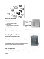
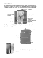
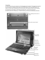
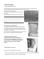
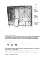
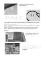
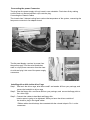
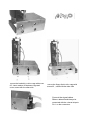
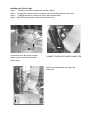
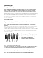
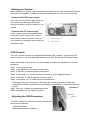
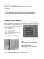
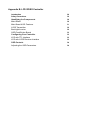
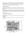
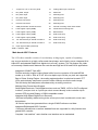
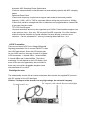
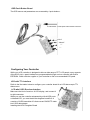
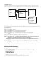
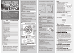
Industrial
PWS-1419T
Portable Computer
System Assembly Guide
A Technical Guide for System Integrators
and Service Technicians
The information contained in this document is believed to be
accurate. However, no responsibility is assumed for its use,
nor for any infringements of patents or other rights of third
party which may result from its use. This information is subject to change without any notice.
Getting Started
Specification
Before You Start
Precautions
Power Connections
4
5
5
5
Non-Autosensing Power Supply
5
ATX Power Switch
5
Ventilation
6
Care for the LCD
Tools and Supplies Needed
Subassembly Contents
Parts Contents
6
6
6
6
Optional CDROM
7
Identifying Parts and Controls
Opening the Side Access Covers
PWA1419T Side Views
Front View
OSD
The Keyboard
7
7
7
9
10
10
Getting Started
General Features
Support passive backplane form factor platforms.
ABS plastic housing with aluminum internal chassis.
14.1” High resolution color martix TFT LCD display
Built-in analog to digital VGA signal conversion board
Add-on card retention system.
Shock mount protection for the hard disk driver
Detachable 104/105-keys keyboard
Built-in touch pad.
Built-in speaker with amplifier
200W AT or ATX power supply (optional DC power supply)
Carrying case with wheel.
Environment
Operating temperature: 0C to 50C, 10-80% humidity
Storage temperature: -20C to 60C, 5-95% humidity
Dimensions & Weight
Dimensions: 15.7”/399mm (W)
13.2”/335mm (H)
10.4”/ 264mm (D)
Weight: 18lbs SKD; approx. 22lbs system
Before You Start
The major component of the subassembly is the chassis, which comes in two models—9 x
ISA slot or 4 x PCI, 5 x ISA slot Passive Backplane. The chassis comes pre-assembled with an
active matrix LCD, LCD controller, power supply, keyboard, ventilation fans and internal
speaker. To complete the system, you must add a system board, CPU and peripheral devices.
Before adding these devices, it is important to follow certain basic safety precautions. You
should become familiar with the chassis both externally and internally. And you should also
have the right tools available to you.
Precautions
Power Connections
Use Supplied Power Cord
The subassembly is shipped with a power cord compatible with the AC wall outlet in your
region.
Non-Autosensing Power Supply
Before plugging in the power cord, examine the power supply to see if you have an
autosensing or non-autosensing power supply.
Autosensing power supplies automatically adjust to the AC constructed of metal and provide
front impact protection for outlet voltage. If your subassembly is shipped with a nonautosensing power supply, there will be a voltage selector switch located near the AC power
connector. Make sure it’s set to the appropriate voltage setting for your power outlet.
ATX Power Switch
The power supply shipped with the ATX chassis may or may not have an ON/OFF switch. To
power up your system where the power supply has an ON/OFF switch, you must first press the
switch to the ON position and then press the ATX power up/down switch located on the front to
start your system.
The ATX power switch found on the front of the chassis DOES NOT turn off the AC
power. To remove AC power from your system, you must unplug the AC power
cord from the AC outlet or the chassis.
Ventilation
The chassis comes with three intake fans and one power supply exhaust fan providing
cooling and air flow. When operating the system, never block any ventilation openings. Always
leave enough room around the chassis to allow adequate air flow.
Care for the LCD
The chassis comes with a pre-assembled active matrix LCD. Liquid crystal displays are
made of glass which will break or crack if mishandled. During system assembly, keep the
keyboard latched to the chassis. The keyboard housing is constructed of metal and provides
front impact protection for the LCD during transportation.
Tools and Supplies Needed
Before beginning your work, make sure you have the following tools and supplies available:
#2 Phillips (cross head) screwdriver.
An anti-static wrist strap (recommended).
Subassembly Contents
The subassembly consists of,
This subassembly guide.
Chassis with pre-assembled LCD, LCD controller, power supply, cooling fans, internal
speaker and keyboard with integrated pointing device.
Power cord.
Carry case.
Parts for installing motherboard and drives.
See Appendix for technical specifications.
Parts Contents
The subassembly parts kit contains the following hardware for installing boards and drives.
1. Round head screw 2Ö long (for securing CD ROM interface board)
2. Round head screw (for securing backplane on the standoff, interface board).
3. Metal washer (use with the flat head and round head screws for mounting the drives)
4. Insulating washer (when installing the motherboard use it with the round head screw 4).
5. Flat head screw (for securing hard driver).
7. Black flat screw (for securing fan filter cover)
9. Motherboard Standoff
10. Round head screw 2Ö short (for securing slim CD ROM)
12. Flat head screw (for card stabilizer).
Optional Slim CD ROM Disk
1. Slim CD ROM interface board
2. CD ROM power cable
(interface to power supply)
3. Audio cable
(interface board to sound card or
SBC Audio out)
4. Slim CD ROM
The pin out may be different for other brand or version of CD ROM & floppy disk
Do not use the CD ROM and floppy from other sources.
Identifying Parts and Controls
Opening the Side Access Covers
The side access door provide side impact protection for the
chassis. The access door must be opened to access the I/O
connectors.
Turn the thumbscrew in the counter clockwise direction to open
the access covers. They swing out toward the back.
PWA 1419T Side Views
Use the photo below to identify components and I/O ports that are accessible from the two
sides of the PWA 1419T chassis. The illustration shows the external connectors and components of a completely assembled SBC system. Your subassembly has only knockout holes
instead.
PWS 1419T Side Views
Use the photo below to identify components and I/O ports that are accessible from the two
sides of the BP-10 chassis. The illustration shows the external connectors and components of
a completely assembled SBC system. Your subassembly has only knockout holes instead.
Handle bar
VGA port & monitor
connector
9 add-on card slot
(optional 12)
I/O port
knockouts.
Internal speaker
connector
AC power Input Socket
Power switch
Power Fan
ATX Power switch
The ATX power switch DOES NOT turn off the AC power. To remove AC power from your
system, you must unplug the AC power cord from the AC outlet or the chassis
reset switch
Tone
Volume
3 intake
fans w/
Filter
3.5”
Floppy
disk.
The CDROM is on the right side of the panel
CDROM
Front View
You access the front panel controls by first disengaging the keyboard. Disengage the keyboard
from the latches by sliding the latch tabs on the bottom sides of the keyboard towards the
center as shown and simultaneously pull the top part of the keyboard away from the chassis.
The keyboard is still hinged on the bottom by latch bolts. Lay down the keyboard.
On the front side of the chassis you’ll find the following controls and subassembly elements:
Push theKeyboard Latches to
center
Pull up the keyboard stand
Power LED
HDD LED
TFT LCD
Num Lock
Caps Locck
Scroll Locck
LED Indicator
Keyboard
Latches
Touch Pad
Anti-slipper
Rubber Knob
OSD button
The OSD button is on the left side of the panel, you have to pull up the panel first to see the
buttons, pull down the small door and pull up the panel with the small bar on the panel.
Pull up the bar
OSD Buttons
“ Manual”
“Select”
“+”
“-“
Small door
The Keyboard
The subassembly comes with a mechanical switch keyboard with an integrated touch pad
device. The signal cable is conceal in the fillister of the keyboard, you have pull it up to connect the connector of the SBC.
The concealed cable
touch pad
PWS-1409T
1. Opening The Chassis
12
Removing the Back Cover
12
Removing the Card Stabilizers
12
Identifying the Internal Parts
12
Removing the Drive Cage
12
Installing the Backplane
13
Installing the Standoffs
13
Connecting the Power Connector
15
.
Installing the Drives to the Drive Cage
15
.
Installing the Driver Cage into the Case
17
Installing the SBC
18
Setting your SBC Jumpers
18
Installing the Add-on Cards
19
Installing the Card Stabilizers
19
Preparing to Start the System
20
Connecting the Video and Input Devices
20
Closing the Back Cover
21
.
Open the chassis
Removing the Back Cover
Face the back of the chassis. Remove all screws as shown. There are 7 screws along the
perimeter of the back cover that holds the back cover to the chassis.
Always power down the system.
Always turn off any peripheral devices connected to
the system.
Always unplug the AC power cord from the chassis.
Face the back of the chassis. Remove
all the release screws as shown. There
are 7 screws along the perimeter of the
back cover that secures it to the
chassis.
Removing the Card Stabilizers
The stabilizer is designed to securely hold down add-on
cards in their expansion slots with plastic hold-down clips.
The stabilizer must be removed prior to adding boards and
components in the chassis.
Step 1. Remove the card stabilizer release screws as shown.
Step 2. Remove the stabilizer and set them aside.
Identifying the Internal Parts
After you remove the card stabilizer you
can check the case contains, the figure is on
the next page. The CDROM cable and audio
cable will come with the slim CDROM
option.
Removing the Drive cage
Remove the 2 screws and take out the cage.
After you removed the drivers cage from the chassis, set it aside. Your are now ready either to
install the drives in the drive cage or install the backplane.
1
4
3
13
1
1. speaker
2 case fan
3 fan board
4 LCD power
cable
5 audio cable
CD audio in
6 driver cage
7 fan cable
to SBC
8 CDROM
signal cable
9 power supply
10 reset cable
11 audio cable
(SBC to speaker)
12 side door
13 mount hole
2
2
2
5
6
7
8
9
10
11
12
Installing The Backplane
Make sure that at no time you are working on any electrical or electronic components while any
part of the system is energized. Always disconnect the power! Use caution to protect the
delicate electronic components. Ground your self during the installation of the motherboard
and other components.
. Installing the Standoffs
#9 Standoffs
#2 3x4 screws to tighten backplane
#4 Washer between the backplane and screws
Take a moment to study the inside of the chassis, making note of the location of the keyboard
Connector if it come with backplane.
Step 1. Slant the backplane retention into the chassis and position it in the area it will be
installed, making sure the alignment of the slots and connectors is correct.
Step 2. Make sure the location of the backplane mounting points. You are going to install
standoffs at those mounting points.
find the mount point of the backplane
insert the stand offs
Thread clock-wise to insert the standoff
reverse to take off the stand off
Your package comes with metal standoffs threaded on one end and tapped on the opposite
end to receive a mounting screw.
Step 3. Now carefully withdraw the backplane and thread the standoffs into the mounting
holes in the chassis.
Step 4. Align the mounting pointing points and insert the screws into the metal standoffs.
Step 5. Tighten the screws. (add washer if the screws will short with the circuit of the
backplane)
Slant the backplane and lower the
backplane into the chassis
Turn clockwise to secure the screws
you may insert the insulating washer between
the screw and backplane to avoid
the shorting
Connecting the power Connector
The plug from the power supply will only insert in one orientation. Push down firmly making
sure the hook on the terminal block clips onto the plug.
Connecting the Chassis Cables
The chassis has 3 internal cooling fan to reduce the temperature of the system, connecting the
fan power connector to fan adapter board.
The flat panel display receives its power from
the power supply. Find the wire bundle that
ends in a 4-pin power connector from the chassis side and plug it into one of the power supply
connectors.
Installing driver disk to the drive Cage
Step 1. Take back the driver cage, take the screw#5 and washer #3 from your package, and
secure the hard disk to driver cage
Step 2. Take the floppy disk and Screw #2 from your package, and secure the floppy disk to
the drive cage.
Step 3. Connect trhe cables to hard disk and floppy disk.
Interior space is going to be tightened. While you have the drivers outside of
the chassis, plug in the signal cables.
Ribbon cables should always be connected with the colored stripe to Pin 1 on the
connectors.
secure the hard disk to drive cage with screw
# 5, insert washer #3 between cage and
screw, same with the other side
secure the floppy disk to drivr cage with
screw# 2, , same with the other side
Connect the signal cables
Ribbon cables should always be
connected with the colored stripe to
Pin 1 on the connectors.
Installing the DriverCage
Step
Step
Step
Step
1. Carefully put the drive cage back into the chassis.
2. Plugging the case fan power conecttor into the interface board for fan power
3. Plugging the power conector for floppy disk and hard disk
4. Align the mounting holes and insert the screws # 2
connect the case fan power connect
(black arrow) to the interface board
(white arrow)
CONNECT THE DRIVE POWER CONNECTOR
Align the mounting holes and insert the
screws # 2
Installing the SBC
Setting your SBC Jumpers
Before installing the motherboard in the chassis, install the CPU and set any dip-switch or
jumper on the SBC. Since jumper and dip-switch settings are board-specific, consult the
manual that comes with the SBC and carefully follow the directions to configure your SBC.
*
Make sure that at no time you are working on any electrical or electronic components while any
part of the system is energized. Always disconnect the power! Use caution to protect the
delicate electronic components. Ground your self during the installation of the motherboard
and other components.
IInstalling the Standoffs
Step1. Locate the slot on the backplane you wish to use. Remove the slot cover screw
and then remove the slot cover.
Step 2. Set the card jumpers or switches according to the manufacturer’s requirements if
necessary.
Step 3. Connect of the small cables from the chassis. The cables are color coded and labeled.
Consult your SBC manual to connect these cables to the correct set of terminal pins.
It may be difficult to know for sure that the polarity of the LED connections is correct. If an LED
fails to light when it should during the test phase, you will be able to shut down and reverse
connections as needed.
1.
2.
3.
4.
5.
Power-on indicator LED (orange and black).
Hard disk LED (blue and black)
System reset switch (white and black).
Power switch (yellow and white).
Internal PC speaker (blue and white).
Step 4. Connect the drive signal cable to SBC
Connect the CD ROM, floppy drive, hard disk drive signal cable to the SBC before the SBC fix.
The ribbon cables should always be connected with the colored stripe to Pin #1 on the
connectors.
Step 5. Hold the card and align the edge connectors with the slot. Firmly push the card into the
slot.
Step 6. Use the screw removed earlier. Insert it into the threaded hole and tighten it.
Connect the signal cable and chassis cable
before fix the SBC
Fix the SBC with screw #2
Installing the Add-on Cards
The chassis has 10 slot openings supporting up to nine (one is used by SBC) add-on cards.
Follow these steps to install add-on cards
Add-on card can be extremely sensitive to electrostatic discharge. Always handle the cards
with care. Hold the card by the metal slot cover or upper corners. Be careful not to touch
the components or gold edge connectors.
Step 1. Locate the slot on the backplane you wish to use. Remove the slot cover screw and
then remove the slot cover.
Step 2. Set the card jumpers or switches according to the manufacturer’s requirements if
necessary.
Step 3. Hold the card and align the edge connectors with the slot. Firmly push the card into the
slot.
Step 4. Use the screw removed earlier. Insert it into the threaded hole and tighten it.
Installing the Card Stabilizers
The procedures of Installing the Card Stabilizers
The card stabilizers are designed to hold down the add-on cards securely in their slots by
pressing the card edges with plastic clips. After you’ve installed all the add-on cards, reinstall
the stabilizers using the following steps.
Step 1. Loosen the screws that hold the plastic clips in their brackets. The clips should be able
to slide freely inside the brackets.
Step 2. Align the stabilizer bars with their
mounting holes on the chassis. Insert the
mounting screws and tighten them. You
may have to pull some of the clips up to
leave enough space between the clip and
the card edge.
There are two set of hole for the plastic clip, one for
ISA theo ther for PCI, you can use the right hole
according the slot type.
Slant the add-on card stabilizer and put it
in the case, then set straight and fix it.
Use screw #7 to secure it.
Use the screw removed earlier. Insert it into
the threaded hole and tighten it.
Step 3. Slide each clip so they come in contact with the top edge of the add-on cards.
While holding the clip firmly against the card edge, tighten the bracket screws.
Step 4. Cut off any excessive part of the plastic clip.
Step 5. Repeat these steps for the other stabilizer.
Press the plastic extender firmly against the
Cut off any excessive part of the plastic clip.
card edge and tighten screw.
Preparing to Start the System
Connecting the Video and Input Devices
The location of your video output, keyboard and pointing device connectors are board
dependent. Connect the video cable to the VGA output connector on your SBC or other graphics card. Connect the keyboard and pointing device connectors to their sockets and firmly push
them into the sockets.
1. Connect the VGA Connector
2. Connect the other connectors for other
device such as Ethernet, Audio device…
Closing the Back Cover
Reinstall the back cover and insert the retaining screws.
Using The System Controls
Starting your System
Systems with ATX Power Supply
Systems with AT Power Supply
OSD Controls
Adjusting the OSD Parameters
Changing Filter for the internal Fan
23
23
23
23
23
23
Starting your System
Before starting your system, plug in the power cord and make sure the video and input device
connectors are plugged in. Release the keyboard latches and lay it flat on your work area.
Systems with ATX Power Supply
If you have an ATX power supply, power up
your system by pressing the ATX power
switch push button on the front panel of your
chassis.
1
2
Systems with AT Power Supply
If your system is passive backplane-based
using an AT power supply, the front push
button power switch is disabled. Power up
your system by pressing the power switch on
the power supply.
1. power switch
2. ATX switch
OSD Controls
The LCD controller includes an integrated RAM-based OSD controller. Through four front
panel controls you can view adjustable features of the LCD through the On-Screen Display.
Follow these steps to activate the on-screen display and make any adjustments to suit your
preference:
Step 1. Power up the system.
Step 2. Press MENU to invoke the on-screen menu.
Step 3. Press SEL to step through the main options.
Step 4. Press either + or - button to bring up sub-menus of the highlighted option.
Step 5. Press SEL to step through the sub-menu options.
Step 6. Press either + or - to modify the selected parameter
Pressing a button once increases or decreases the numerical value by a single digit.
Holding down a button increases the rate of change. Press MENU to return to the previous
screen.
OSD Buttons
Step 7. After you’ve made your adjustments press
MENU repeatedly until the OSD is turned off.
Adjusting the OSD Parameters
The OSD consists of a main menu and sub-menus with
the following selections:
Brightness MENU
Manual adjustment the brightness
“ Manual”
“ Select”
“+”
“-“
Contrast Menu
Contrast: Manual adjustment the contrast
Sub-CONTRAST: Manual adjustment of individual RGB channel contrast.
Position Menu
H-size: Adjust the horizontal size
Clock phase: Manual adjustment of the sample pixel clock phase.
H.POSITION: Adjusts the horizontal image position within the display area of the LCD.
V.POSITION: Adjusts the vertical image position within the display area of the LCD.
Information
Show the current display resolution, vertical and horizontal frequency
Changing Filter for the internal Fan
The internal fan is the entrance of the system air flow. It may contain dust during the
long use. Change or clean the filter for the fan will improve the system air flow. Please
follow the steps to clean or change the filter.
Step 1. The filter is under a plastic cage on
the right side of case.
Step 2. Take off thescrew
Step 3. Remove the cage
Step 4. Remove the filter
Step 5. Replace a new one or you may
clean the original one
Step 6. Move back the cage, and insert
back the screws
Step 1. The second and third filters are
under a plastic cage on the right side of
case.
Step 2. push the side of the plastic cage
Step 3. Remove the cage
Step 4. Remove the filter
Step 5. Replace a new one or you may
clean the original one
Step 6. Move back the cage,
Caution: Please make sure the filter is dry when you restore it
Appendix A.
Trouble Shooting Techniques
No screen after pressing front power switch
Power supply fan not spinning:
Power supply fan is spinning and LCD has no backlight
Power supply fan is spinning and LCD has backlight and
power LED is on:
26
26
26
26
26
LCD screen shows garbage or bad characters or vertical/horizontal
color lines or bar:
26
LCD screen works fine in Windows but acted funny when run
ning certain programs or games:
Keyboard and pointing device not responding
27
27
Trouble Shooting Techniques
No screen after pressing front power switch
Power supply fan not spinning:
Check power source.
Check power cord connection.
Check if all power connectors inside the chassis have been properly connected.
Check the ATX power switch cable to SBC(or motherboard) have been properly connected
Check main power switch on power supply (PS-2 power supply for BP-7 model).
Check the power-on Cable between SBC and backplane (there is a power- on cable
between SBC and back plane, check the cable is on the right position and direction)
Check voltage selection if there is one on the power supply unit.
Power supply fan is spinning and LCD has no backlight
(Backlight can be observed along the top and bottom edge of the LCD screen.)
Check if the power supply to the LCD screen is connected.
Power supply fan is spinning and LCD has backlight and power LED is on:
Check if the video cable is properly connected.
If the system seems to be booting up (hard disk drive cranking up) then detach the video cable
to the internal LCD screen and attach to an external good CRT type monitor. If external monitor has video then it is a bad LCD screen or bad internal cabling.
If the system does not seems to be booting up (no hard disk activity) and no video when connected to external good CRT monitor, then check system for shorts, reseat video and all other
add-on cards. Check memory module installation. Listen for error beeps from the
motherboard. If all failed then remove system from the enclosure and check motherboard
subassembly with an external set of power supply and display to isolate the problem. Check if
the motherboard is not shorted to the standoff. If all failed, call your vendor for support where
this enclosure was purchased.
LCD screen shows garbage or bad characters or vertical/horizontal color lines
or bar:
Detach the video connection to the LCD screen and attach to a good external CRT type
monitor. If the external CRT monitor shows normal video then it could be compatibility issue.
Replace the VGA card and use a different VGA card and try it again with the LCD screen. If it
still failed then it could be a bad conversion board or loose cable inside the LCD subassembly.
If the external CRT monitor shows similar garbage character then it is a bad video card.
(please also check the pins in the 15-pin D-type connector are aligned to the hole of the VGA
card)
LCD SCREEN works fine in Windows but acted funny when running certain programs or games:
The built-in Intelligent Analog-Digital conversion board (AD board) should adjust the screen to
the proper resolution to fill the entire display. However, certain programs or display modes
might cause the AD board to not align or sync properly. Check if the program that you are
running is running under supported resolution. (The max resolution on 12.1” is 800 * 600, 13.
1”, 14.1”, 15” is 1024 *768. and the vertical frequency should be between 60Hz and 70Hz)
You can also try adjusting the OSD to manually adjust the resolution.
The display is not on the LCD center
Adjust the OSD to manually adjust the resolution. Check the VGA output. (The max resolu-
tion on 12.1” is 800 * 600, 13.1”, 14.1”, 15” is 1024 *768. and the vertical frequency
should be between 60Hz and 70Hz)
Keyboard and pointing device not responding
Remove both the PS-2 connections on the motherboard and try using an external regular
keyboard and mouse. If an external keyboard or pointing device is working properly then you
have a bad keyboard or keyboard cable assembly.
There will be 1 Y-type extension cable come wit your SBC, The one-connector end connect to
the SBC, and there are 2 connectors for the other end, one is for the keyboard, the other for
the touch pad. Make sure that you connect to the right connector.
Appendix B: LCD VIDEO Controller
Introduction
Safety Precautions
29
30
Identifying the Components
Main Board
Main Board ASIC Features
LVDS Transmitter
Backlight Inverter
OSD Push Button Board
Configuring Your Controller
LCD with TTL Interface
LCD with LVDS Receiver Interface
OSD Controls
Adjusting the OSD Parameters
30
30
31
32
32
33
33
33
33
34
34
Introduction
The LCD video controller subassembly is an “in-monitor” design build around a high
performance ASIC technology that enable the display of analog VGA signals on a flat
panel LCD display. The LCD video board provides all the electronic necessary to drive
a TFT flat panel display from VGA (640x480) up to (1280x1024) source.
In feature a multi-interface LCD video controller board that support TTL, LVDS and
TMDS protocol-base flat panel display. The controller includes auto resolution adjustment and versatile On-Screen-Display Controller adjustment.
There are three basic functional within the LCD video Controller:
The video receiver circuit
The LCD driver circuit, and
The inverter
How the LCD Video Controller connects to the LCD screen
Inverter
LCD Screen
LCD Video
Controller
OSD Interface Board
12V Power Source
Analog VGA input
source from VGA card
A computer’s video interface produces an analog video signal. Since LCD monitors
require a digital signal, a video receiver circuit is require to convert the analog video
signal into a digital video format that is accepted by the LCD monitor’s driver circuit.
Once the analog signal has been converted to a digital format, the digital signal is
passed to the LCD driver circuit.
This converts the digital video signal into the row and column information that actually
that pixels on and off on the display.
The light source for most flat panel displays is a cold cathode fluorescent backlight.
These backlights run on high AC voltage provided by an inverter that converts the
supplied DC power to AC and steps its voltage up for start-up. Once the backlight is
started, the inverter drops the voltage down to its operating level.
Safety Precautions
Before you configure and assemble the controller board for your flat panel display, it is
important to become familiar with the board layout and also follow certain basic safety
precautions
Make sure that at no time you are working on any electrical or electronic components while any
part of the system is energized Always disconnect the power! Use caution to protect the delicate electronic components. Ground your self during the installation of the motherboard and
other components.
Identifying the Components
Take a moment to familiarize yourself with the board layout, mounting point locations, jumpers
and connectors
Main board
The main board consists of the ASIC chip, firmware IC, supports electronics and interface
connectors.
1
Jumper for 3.3V or 5V TFT panel.
15
Analog video input connector
2
DC power out put
16
Reserv ed
3
DC power input
17
Mounting hole
4
DC power input
18
Mounting hole
5
Inverter c onnect ors
19
Mounting hole
6
Inverter c onnect ors
20
Mounting hole
7
OSD push-button board connec tor
21
Ground of Analog video cable shield
*
8
LVDS signal output (2C8B)
22
LVDS board mounting hole
9
LVDS signal output (1C8B)
23
BIOS Socket
10
LVDS signal output (1C6B)
24
8 Bit LV DS chip
11
LVDS signal output (2C6B)
25
6 Bit LV DS chip
12
TTL interface 30-pin header connect or.
26
8 Bit LV DS chip
13
TTL interface 40-pin header connect or.
27
6 Bit LV DS chip
14
Input signal enable (reserv ed)
2C8B: 2 Channel 8 BIT
Main board ASIC Features
The LCD video controller consists of a revolutionary scaling engine, capable of expanding
any source resolution to a highly uniform and sharp image, and critically proven integrated 8 bit
triple-ADC and patented Rapid-Lock digital clock recovery system. This rich feature set yields
an extremely suitable match between the controller and high and XGA and SXGA applications.
Integrated 135 MHZ Triple ADC.
Flexible resolution support without frame buffer from low resolution VGA and NEC98
modes up to 1280 x 1024 at 75 HZ. All color depths up to 24 bits per pixel are supported.
Best of Class Scaling Engine - the scaling engine algorithm is optimized to match TFT
LCDs optical display response to provide uniform intensity across the entire image.
Text font clarity and sharpness are enhanced by re-scaling convolver.
Multiple Video Format Input Support.
Serial Digital Receivers- Serial digital receivers such as TMDS, LVDS or GVIF configured
in either 1 pixel per clock or 2 pixels per clock connect directly to the controller chip to
create a DFP plug and Display or DISM compatible monitor.
Integrated High Speed Digital Clock Recovery
-Solid and completely stable locking to the source pixel clock is achieved in worst case
test patterns.
-All clocks required are generated from a single 50 MHZ reference oscillator.
Integrated RAM based OSD Controller
-Customer defined fonts as well as standard fonts are supported in a fully featured integrated OSD controller.
Complete “look and feel” and a familiar user interface can be maintained.
Automatic ADC Sampling Phase Optimization
-Performs measurements so that firmware can automatically optimize the ADC sampling
phase.
Optimized Panel Clock
-Panel clock frequency is optimized to support each mode at the lowest possible
frequency. 1280 x 1024 x 75HZ is supported without driving the panel clock at 135Mhz.
-Panel clock pad drive strength and clock to data skew are programmable to reduce EMI
in the panel interface cable.
TFT LCD Panel Support
-All panel resolutions and sizes are supported up to SXGA- Panel interface supports one
or two pixel per clock, Sync only, DE only and Sync/DE composite. Four Wire Interface
to Micro-controller Simple 4 wire serial interface connects directly to monitor microcontroller. . Can be expanded to 7 wires by increasing data width from 1 to 4.
LVDS Transmitter
There are on board LVDS (Low Voltage Differential
Signaling) transmitter ICs to convert CMOS/TTL data
into LVDS data stream. Since the LCD display has
its own LVDS receiver, there are 4 kinds of on board
LVDS transmitter: 1 channel 6Bits; 1 channel 8Bits;
2 channel 6Bits and 2 channel 8Bits. The built-in
transmitter ICs will depend on the LCD display. Also
some LCDs are not supported by the on board ICs,
there may come with a pluggable daughter board
with transmitter ICs to use it.
Backlight Inverter
The subassembly comes with an inverter subsystem that converts the supplied DC power to
high DC voltage for the LCD backlight.
Caution: The output of the inverter is a very high voltage, do not touch it anyway.
To main board 5 or 6
DC output to cold cathode fluorescent backlight
OSD Push Button Board
The OSD menus and parameters are accessed by 4 push buttons .
to mainboard “7 OSD push-button board connector”
“Select”
“ Manual”
“+”
“-“
Configuring Your Controller
While your LCD controller is designed to drive a wide range of TFT LCD panels, many aspects
of the ASIC chip’s panel interface are programmable through a micro-controller with built-in
EEPROM. Check with the supplier of your controller to find a recommended LCD panel.
LCD with TTL Interface
Refer to the illustration below to configure your controller board for a LCD that accepts TTL
data source.
LCD wits LVDS Receiver Interface
Make sure the kind of receiver of LCD display, and connect it
to right connecter.
When you use the controller subassembly with aLVDS protocol-based LCD, you must install the daughter board first. It
consists of LVDS transmitter ICs that convert CMOS/TTL data
into LVDS data stream.
Installing the LVDS Daughter Board
OSD Controls
The LCD controller includes an integrated RAM-based OSD controller. Through four front
panel controls you can view adjustable features of the LCD through the On-Screen Display.
Brightness
Contrast
Position
Information
All Reset
Brightness
Contrast
Sub. Contrast
H. Size
Clock Phase
R
G
B
H. Position
V. Position
Information
1024 x 768
H. f 56.4KHz
V. f. 70 Hz
Follow these steps to activate the on-screen display and make any adjustments to suit
your preference:
Step 1.
Step 2.
Step 3.
Step 4.
Power up the system.
Press MENU ▲ to step through the main options.
Press SEL ▼ to step through the main options.
Press either + or – button to bring up sub-menus of the highlighted
option.
Step 5. Press SEL ▼ to step through the sub-menu options.
Step 6. Press either + or – to modify the selected parameter value. Pressing a button once
increases or decreases the numerical value by a single digit.
Holding down a button increases the rate of change. Press MENU ▲ to the previous
screen.
Step 7. After you’ve made your adjustments press MENU ▲ repeatedly until the OSD is
turned off.
Adjusting the OSD Parameters
The OSD consists of a main menu and sub-menus with the following selections:
BRIGHTNESS MENU
Adjusts the black level.
CONTRAST MENU
Contrast: Adjusts the contrast.
SUB: Manual adjustment of individual RGB channel contrast.
POSITION
H-SIZE: Adjustment of the vertical image size
CKOCK PHASE: adjustment of the ADC sample pixel clock.
H. POSITION: Adjusts the horizontal image position within the display area of the LCD.
V. POSITION: Adjusts the vertical image position within the display area of the LCD.
INFORMATION
Shows the current display resolution, horizontal and vertical frequency
Auto adjust: Press SEL key before menu popup
Save: Auto-save the value whenever the popup menu close